EP3764651A1 - Loop filter apparatus and image decoding apparatus - Google Patents
Loop filter apparatus and image decoding apparatus Download PDFInfo
- Publication number
- EP3764651A1 EP3764651A1 EP20178490.7A EP20178490A EP3764651A1 EP 3764651 A1 EP3764651 A1 EP 3764651A1 EP 20178490 A EP20178490 A EP 20178490A EP 3764651 A1 EP3764651 A1 EP 3764651A1
- Authority
- EP
- European Patent Office
- Prior art keywords
- channels
- feature maps
- image
- loop filter
- perform
- Prior art date
- Legal status (The legal status is an assumption and is not a legal conclusion. Google has not performed a legal analysis and makes no representation as to the accuracy of the status listed.)
- Withdrawn
Links
Images


Classifications
-
- H—ELECTRICITY
- H04—ELECTRIC COMMUNICATION TECHNIQUE
- H04N—PICTORIAL COMMUNICATION, e.g. TELEVISION
- H04N19/00—Methods or arrangements for coding, decoding, compressing or decompressing digital video signals
- H04N19/80—Details of filtering operations specially adapted for video compression, e.g. for pixel interpolation
- H04N19/82—Details of filtering operations specially adapted for video compression, e.g. for pixel interpolation involving filtering within a prediction loop
-
- G—PHYSICS
- G06—COMPUTING OR CALCULATING; COUNTING
- G06T—IMAGE DATA PROCESSING OR GENERATION, IN GENERAL
- G06T9/00—Image coding
- G06T9/002—Image coding using neural networks
-
- G—PHYSICS
- G06—COMPUTING OR CALCULATING; COUNTING
- G06N—COMPUTING ARRANGEMENTS BASED ON SPECIFIC COMPUTATIONAL MODELS
- G06N3/00—Computing arrangements based on biological models
- G06N3/02—Neural networks
- G06N3/04—Architecture, e.g. interconnection topology
- G06N3/045—Combinations of networks
-
- G—PHYSICS
- G06—COMPUTING OR CALCULATING; COUNTING
- G06N—COMPUTING ARRANGEMENTS BASED ON SPECIFIC COMPUTATIONAL MODELS
- G06N3/00—Computing arrangements based on biological models
- G06N3/02—Neural networks
- G06N3/04—Architecture, e.g. interconnection topology
- G06N3/0464—Convolutional networks [CNN, ConvNet]
-
- G—PHYSICS
- G06—COMPUTING OR CALCULATING; COUNTING
- G06T—IMAGE DATA PROCESSING OR GENERATION, IN GENERAL
- G06T3/00—Geometric image transformations in the plane of the image
- G06T3/40—Scaling of whole images or parts thereof, e.g. expanding or contracting
- G06T3/4046—Scaling of whole images or parts thereof, e.g. expanding or contracting using neural networks
-
- H—ELECTRICITY
- H04—ELECTRIC COMMUNICATION TECHNIQUE
- H04N—PICTORIAL COMMUNICATION, e.g. TELEVISION
- H04N19/00—Methods or arrangements for coding, decoding, compressing or decompressing digital video signals
-
- H—ELECTRICITY
- H04—ELECTRIC COMMUNICATION TECHNIQUE
- H04N—PICTORIAL COMMUNICATION, e.g. TELEVISION
- H04N19/00—Methods or arrangements for coding, decoding, compressing or decompressing digital video signals
- H04N19/10—Methods or arrangements for coding, decoding, compressing or decompressing digital video signals using adaptive coding
- H04N19/102—Methods or arrangements for coding, decoding, compressing or decompressing digital video signals using adaptive coding characterised by the element, parameter or selection affected or controlled by the adaptive coding
- H04N19/117—Filters, e.g. for pre-processing or post-processing
-
- H—ELECTRICITY
- H04—ELECTRIC COMMUNICATION TECHNIQUE
- H04N—PICTORIAL COMMUNICATION, e.g. TELEVISION
- H04N19/00—Methods or arrangements for coding, decoding, compressing or decompressing digital video signals
- H04N19/10—Methods or arrangements for coding, decoding, compressing or decompressing digital video signals using adaptive coding
- H04N19/102—Methods or arrangements for coding, decoding, compressing or decompressing digital video signals using adaptive coding characterised by the element, parameter or selection affected or controlled by the adaptive coding
- H04N19/124—Quantisation
-
- H—ELECTRICITY
- H04—ELECTRIC COMMUNICATION TECHNIQUE
- H04N—PICTORIAL COMMUNICATION, e.g. TELEVISION
- H04N19/00—Methods or arrangements for coding, decoding, compressing or decompressing digital video signals
- H04N19/10—Methods or arrangements for coding, decoding, compressing or decompressing digital video signals using adaptive coding
- H04N19/102—Methods or arrangements for coding, decoding, compressing or decompressing digital video signals using adaptive coding characterised by the element, parameter or selection affected or controlled by the adaptive coding
- H04N19/132—Sampling, masking or truncation of coding units, e.g. adaptive resampling, frame skipping, frame interpolation or high-frequency transform coefficient masking
-
- H—ELECTRICITY
- H04—ELECTRIC COMMUNICATION TECHNIQUE
- H04N—PICTORIAL COMMUNICATION, e.g. TELEVISION
- H04N19/00—Methods or arrangements for coding, decoding, compressing or decompressing digital video signals
- H04N19/10—Methods or arrangements for coding, decoding, compressing or decompressing digital video signals using adaptive coding
- H04N19/134—Methods or arrangements for coding, decoding, compressing or decompressing digital video signals using adaptive coding characterised by the element, parameter or criterion affecting or controlling the adaptive coding
- H04N19/136—Incoming video signal characteristics or properties
-
- H—ELECTRICITY
- H04—ELECTRIC COMMUNICATION TECHNIQUE
- H04N—PICTORIAL COMMUNICATION, e.g. TELEVISION
- H04N19/00—Methods or arrangements for coding, decoding, compressing or decompressing digital video signals
- H04N19/10—Methods or arrangements for coding, decoding, compressing or decompressing digital video signals using adaptive coding
- H04N19/134—Methods or arrangements for coding, decoding, compressing or decompressing digital video signals using adaptive coding characterised by the element, parameter or criterion affecting or controlling the adaptive coding
- H04N19/157—Assigned coding mode, i.e. the coding mode being predefined or preselected to be further used for selection of another element or parameter
- H04N19/159—Prediction type, e.g. intra-frame, inter-frame or bidirectional frame prediction
-
- H—ELECTRICITY
- H04—ELECTRIC COMMUNICATION TECHNIQUE
- H04N—PICTORIAL COMMUNICATION, e.g. TELEVISION
- H04N19/00—Methods or arrangements for coding, decoding, compressing or decompressing digital video signals
- H04N19/10—Methods or arrangements for coding, decoding, compressing or decompressing digital video signals using adaptive coding
- H04N19/169—Methods or arrangements for coding, decoding, compressing or decompressing digital video signals using adaptive coding characterised by the coding unit, i.e. the structural portion or semantic portion of the video signal being the object or the subject of the adaptive coding
- H04N19/17—Methods or arrangements for coding, decoding, compressing or decompressing digital video signals using adaptive coding characterised by the coding unit, i.e. the structural portion or semantic portion of the video signal being the object or the subject of the adaptive coding the unit being an image region, e.g. an object
- H04N19/176—Methods or arrangements for coding, decoding, compressing or decompressing digital video signals using adaptive coding characterised by the coding unit, i.e. the structural portion or semantic portion of the video signal being the object or the subject of the adaptive coding the unit being an image region, e.g. an object the region being a block, e.g. a macroblock
-
- H—ELECTRICITY
- H04—ELECTRIC COMMUNICATION TECHNIQUE
- H04N—PICTORIAL COMMUNICATION, e.g. TELEVISION
- H04N19/00—Methods or arrangements for coding, decoding, compressing or decompressing digital video signals
- H04N19/44—Decoders specially adapted therefor, e.g. video decoders which are asymmetric with respect to the encoder
-
- H—ELECTRICITY
- H04—ELECTRIC COMMUNICATION TECHNIQUE
- H04N—PICTORIAL COMMUNICATION, e.g. TELEVISION
- H04N19/00—Methods or arrangements for coding, decoding, compressing or decompressing digital video signals
- H04N19/50—Methods or arrangements for coding, decoding, compressing or decompressing digital video signals using predictive coding
- H04N19/59—Methods or arrangements for coding, decoding, compressing or decompressing digital video signals using predictive coding involving spatial sub-sampling or interpolation, e.g. alteration of picture size or resolution
-
- H—ELECTRICITY
- H04—ELECTRIC COMMUNICATION TECHNIQUE
- H04N—PICTORIAL COMMUNICATION, e.g. TELEVISION
- H04N19/00—Methods or arrangements for coding, decoding, compressing or decompressing digital video signals
- H04N19/60—Methods or arrangements for coding, decoding, compressing or decompressing digital video signals using transform coding
-
- H—ELECTRICITY
- H04—ELECTRIC COMMUNICATION TECHNIQUE
- H04N—PICTORIAL COMMUNICATION, e.g. TELEVISION
- H04N19/00—Methods or arrangements for coding, decoding, compressing or decompressing digital video signals
- H04N19/80—Details of filtering operations specially adapted for video compression, e.g. for pixel interpolation
-
- H—ELECTRICITY
- H04—ELECTRIC COMMUNICATION TECHNIQUE
- H04N—PICTORIAL COMMUNICATION, e.g. TELEVISION
- H04N19/00—Methods or arrangements for coding, decoding, compressing or decompressing digital video signals
- H04N19/85—Methods or arrangements for coding, decoding, compressing or decompressing digital video signals using pre-processing or post-processing specially adapted for video compression
- H04N19/86—Methods or arrangements for coding, decoding, compressing or decompressing digital video signals using pre-processing or post-processing specially adapted for video compression involving reduction of coding artifacts, e.g. of blockiness
Definitions
- This disclosure relates to the field of video coding technologies and image compression technologies.
- Lossy images and video compression algorithms may cause artifacts, including blocking, blurring and ringing, as well as sample distortion.
- CNN convolutional neural network
- traditional video compression software such as VTM
- a deblocking filter such as a sample adaptive offset (SAO) filter
- an adaptive loop filter such as ALF
- Embodiments of this disclosure provide a loop filter apparatus and an image decoding apparatus, in which functions of the loop filter are carried out by using a convolutional neural network, which may reduce a difference between a reconstructed frame and an original frame, reduce an amount of computation, and save processing time of the CNN.
- a loop filter apparatus including:
- an image decoding apparatus including:
- a loop filter method including:
- an image decoding method including:
- a computer readable program which, when executed in an image processing device, will cause the image processing device to carry out the method as described in the third or fourth aspect.
- a computer storage medium including a computer readable program, which will cause an image processing device to carry out the method as described in the third or fourth aspect.
- An advantage of the embodiments of this disclosure exists in that according to any one of the above-described aspects of the embodiments of this disclosure, functions of the loop filter are carried out by using a convolutional neural network, which may reduce a difference between a reconstructed frame and an original frame, reduce an amount of computation, and save processing time of the CNN
- terms “first”, and “second”, etc. are used to differentiate different elements with respect to names, and do not indicate spatial arrangement or temporal orders of these elements, and these elements should not be limited by these terms.
- Terms “and/or” include any one and all combinations of one or more relevantly listed terms.
- Terms “contain”, “include” and “have” refer to existence of stated features, elements, components, or assemblies, but do not exclude existence or addition of one or more other features, elements, components, or assemblies.
- single forms “a”, and “the”, etc. include plural forms, and should be understood as “a kind of' or “a type of' in a broad sense, but should not defined as a meaning of "one”; and the term “the” should be understood as including both a single form and a plural form, except specified otherwise.
- the term “according to” should be understood as “at least partially according to”, the term “based on” should be understood as “at least partially based on”, except specified otherwise.
- video frames are defined as intra-frames and inter-frames.
- Intra-frames are frames that are compressed without reference to other frames.
- Inter-frames are frames that are compressed with reference to other frames.
- a traditional loop filter is effective in intra-frames or inter-frames prediction. Since a convolutional neural network may be applied to single image restoration, a CNN is used in this disclosure to process sub-sampled video frames based on intra-frame compression.
- FIG. 1 is a schematic diagram of the image compression system of the embodiment of this disclosure.
- an image compression system 100 of the embodiment of this disclosure includes a first processing unit 101, an entropy encoding apparatus 102 and an image decoding apparatus 103.
- the first processing unit 101 is configured to perform transform (T) and quantization (Q) processing on an input image, which is denoted by T/Q in FIG. 1 ;
- the entropy encoding apparatus 102 is configured to perform entropy encoding on output of the first processing unit 101, and output bit streams;
- the image decoding apparatus 103 is configured to perform decoding processing on the output of the first processing unit 101, and perform intra prediction and inter prediction.
- the image decoding apparatus 103 includes a second processing unit 1031, a CNN filtering unit 1032, an SAO filtering unit 1033, and an ALF filtering unit 1034.
- the second processing unit 1031 is configured to perform de-transform (IT) and de-quantization (IQ) processing on received code streams (bit streams), which is denoted by IT/IQ in FIG.
- the CNN filtering unit 1032 is configured to perform first time of filtering processing on output of the first processing unit 1031;
- the SAO filtering unit 1033 is configured to perform second time of filtering processing on output of the CNN filtering unit 1032; and
- the ALF filtering unit 1034 is configured to perform third time of filtering processing on output of the SAO filtering unit 1033, take a filtered image as a reconstructed image and output the reconstructed image.
- the image decoding apparatus 103 further includes a first predicting unit 1035, a second predicting unit 1036 and a motion estimating unit 1037.
- the first predicting unit 1035 is configured to perform intra prediction on the output of the second processing unit 1031;
- the second predicting unit 1036 is configured to perform inter prediction on the output of the ALF filtering unit 1034 according to a motion estimation result and a reference frame;
- the motion estimating unit 1037 is configured to perform motion estimation according to an input video frame and the reference frame, to obtain the motion estimation result and provide the motion estimation result to the second predicting unit 1036.
- the CNN filtering unit 1032 is used to replace a deblocking filter, and a convolutional neural network is used to implement a function of a loop filter, which may reduce a difference between a reconstructed frame and an original frame, reduce an amount of computation, and save processing time of the CNN.
- the CNN filtering unit 1032 of the embodiment of this disclosure shall be described below.
- FIG. 2 is a schematic diagram of a loop filter apparatus 200 of this embodiment.
- the loop filter apparatus 200 functions as the CNN filtering unit 1032 of FIG. 1 , that is, the CNN filtering unit 1032 of FIG. 1 may include the loop filter apparatus 200 of FIG. 2 .
- the loop filtering apparatus 200 includes a down-sampling unit 201, a residual learning unit 202 and an up-sampling unit 203.
- the down-sampling unit 201 is configured to perform down sampling on a frame of an input reconstructed image to obtain feature maps of N channels;
- the residual learning unit 202 is configured to perform residual learning on input feature maps of N channels to obtain feature maps of N channels;
- the up-sampling unit 203 is configured to perform up sampling on input feature maps of N channels to obtain an image of an original size of the reconstructed image.
- the down-sampling unit 201 may perform the down sampling on the frame of input reconstructed image via a convolutional layer (referred to as a first convolutional layer, or a down-sampling convolutional layer) to obtain the feature maps of N channels.
- a convolutional layer referred to as a first convolutional layer, or a down-sampling convolutional layer
- a kernel size, the number of channels and a stride of convolution of the convolutional layer are not limited in the embodiment of this disclosure.
- the convolutional layer may be a 4 ⁇ 4 32-channel convolutional layer with a stride of convolution of (4, 4).
- down-sampling may be performed on the frame of input reconstructed image via the convolutional layer, in which the frame the reconstructed image is down-sampled from N1 ⁇ N1 to (N1/4) ⁇ (N1/4), where, N1 is the number of pixels.
- N1 is the number of pixels.
- down-sampling is performed on a 64 ⁇ 64 image frame by using the above 4 ⁇ 4 ⁇ 32 convolutional layer, and 16 ⁇ 16 feature maps of 32 channels may be obtained, as shown in FIG. 3 .
- the first convolutional layer it is possible to ensure that useful information is not lost and useless information is removed.
- the residual learning unit 202 may perform the residual learning on input feature maps of N channels respectively via multiple residual blocks, to obtain feature maps of N channels respectively and output the feature maps of N channels respectively. With the multiple residual blocks, performance of restoration may be improved.
- FIG. 4 is a schematic diagram of an embodiment of a residual block. As shown in FIG. 4 , the residual block may include a second convolutional layer 401, a third convolutional layer 402 and a fourth convolutional layer 403.
- the second convolutional layer 401 is configured to perform dimension increasing processing on input feature maps of N channels to obtain feature maps of M channels, M being greater than N;
- the third convolutional layer 402 is configured to perform dimension reducing processing on the feature maps of M channels from the second convolutional layer 401 to obtain feature maps of N channels;
- the fourth convolutional layer 403 is configured to perform feature extraction on the feature maps of N channels from the third convolutional layer 402 to obtain feature maps of N channels and output the feature maps of N channels.
- the second convolutional layer 401 may be a 1 ⁇ 1 192-channel convolutional layer, and via this convolutional layer, dimensions may be expanded;
- the third convolutional layer 402 may be a 1 ⁇ 1 32-channel convolutional layer, and via this convolutional layer, dimensions may be reduced;
- the fourth convolutional layer 403 may be a 3 ⁇ 3 32-channel depthwise-separable convolutional layer, and via this convolutional layer, convolution parameters may be reduced.
- the up-sampling unit 203 may perform the up sampling on input feature maps of N channels via a convolutional layer (referred to as a fifth convolutional layer) and an integration layer, to obtain an image of an original size of the above reconstructed image.
- a convolutional layer referred to as a fifth convolutional layer
- an integration layer to obtain an image of an original size of the above reconstructed image.
- the fifth convolutional layer may compress input feature maps of N channels to obtain feature maps of N channels
- the integration layer may integrate the feature maps of N channels from the fifth convolutional layer, combine them into an image, and take the image as the image of an original size of the reconstructed image.
- the fifth convolutional layer may be a 3 ⁇ 3 4-channel convolutional layer
- the integration layer may be a pixel shuffle layer (emulation + permutation), which may integrate input 32 ⁇ 32 feature maps of 4 channels into 64 ⁇ 64 feature maps of 1 channel, as shown in FIG. 5 , and the 64 ⁇ 64 feature map is a result of difference learnt by a neural network.
- the loop filter apparatus 200 may further include a first calculating unit 204 and a second calculating unit 205.
- the first calculating unit 204 is configured to divide the frame of input reconstructed image by a quantization step, and take a result of calculation as input of the down-sampling unit 201
- the second calculating unit 205 is configured to multiply an image of an original size output by the up-sampling unit 203 by the quantization step, and take a result of calculation as the image of an original size and output the image of an original size.
- the quantization operation usually consists of two parts, namely forward quantization (FQ or Q) in an encoder and inverse quantization (IQ) in a decoder. And the quantization operation can be used to reduce the accuracy of image data after applying transformation (T).
- FQ round X / Qstep
- Y FQ ⁇ Qstep ; where, X is a value before the quantization, Y is a value after the inverse quantization, and Qstep is a quantization step.
- a loss of the quantization is induced by a function round, and in video compression, a quantization parameter varies in a range of 0-51, and a relationship between QP and Qstep is as follows: QP Qstep QP Qstep QP Qstep QP Qstep QP Qstep 0 0.625 11 2.25 22 8 33 28 44 104 1 0.6875 12 2.5 23 9 34 32 45 112 2 0.8125 13 2.75 24 10 35 36 46 128 3 0.875 14 3.25 25 11 36 40 47 144 4 1 15 3.5 26 13 37 44 48 160 5 1.125 16 4 27 14 38 52 49 176 6 1.25 17 4.5 28 16 39 56 50 208 7 1.375 18 5 29 18 40 64 51 224 8 1.625 19 5.5 30 20 41 72 9 1.75 20 6.5 31 22 42 80 10 2 21 7 32 26 43 88
- Qstep obtained from QP may reduce a difference between videos encoded by different QPs.
- the reconstructed image or frame is divided by Qstep before the downsampling, which may control blocking of different images at the same level, and in the embodiment of this disclosure, multiplication by Qstep is performed after the upsampling, which may restore pixel values.
- a CNN model may use video sequences of different QPs.
- FIG. 6 is a schematic diagram of a network structure of the loop filter apparatus 200 of the embodiment of this disclosure.
- the reconstructed image is divided by Qstep and then output to a down-sampling convolutional layer 601.
- the down-sampling convolutional layer 601 performs down-sampling on input reconstructed image to obtain feature maps of N channels and outputs the feature maps of N channels to a residual block 602.
- the residual block 602 performs residual learning on the feature maps of N channels to obtain feature maps of N channels and outputs the feature maps of N channels to a residual block 603, the residual block 603 performs the same processing as the residual block 602 to obtain feature maps of N channels and outputs the feature maps of N channels to a residual block 604, the residual block 604 performs the same processing as the residual block 602 to obtain feature maps of N channels and outputs the feature maps of N channels to a residual block 605, the residual block 605 performs the same processing as the residual block 602 to obtain feature maps of N channels and outputs the feature maps of N channels to an up-sampling convolutional layer 606, and the up-sampling convolutional layer 606 performs up-sampling on input feature maps of N channels to obtain image of the original size of the reconstructed image and output the image of the original size, and the image of the original size is output after being multiplied by Qstep to obtain a filtering result.
- the CNN filter 1032 may include the loop filtering apparatus 200, and furthermore, the CNN filter 1032 may include other components or assemblies, and the embodiment of this disclosure is not limited thereto.
- the above loop filtering apparatus 200 may be used to process intra frames; however, this embodiment is not limited thereto.
- loop filter apparatus 200 of the embodiment of this disclosure is only schematically described in FIG. 2 ; however, this disclosure is not limited thereto.
- connection relationships between the modules or components may be appropriately adjusted, and furthermore, some other modules or components may be added, or some modules or components therein may be reduced. And appropriate variants may be made by those skilled in the art according to the above contents, without being limited to what is contained in FIG. 2 .
- the image compression system of the embodiment of this disclosure carries out the functions of the loop filter by using a convolutional neural network, which may reduce a difference between a reconstructed frame and an original frame, reduce an amount of computation, and save processing time of the CNN
- FIG. 2 is a schematic diagram of the loop filter apparatus 200 of the embodiment of this disclosure
- FIG. 6 is a schematic diagram of a network structure of the loop filter apparatus of the embodiment of this disclosure.
- the loop filter apparatus has been described in Embodiment 1 in detail, its contents are incorporated herein, and shall not be described herein any further.
- a convolutional neural network is used to carry out the functions of the loop filter, which may reduce a difference between a reconstructed frame and an original frame, reduce an amount of computation, and save processing time of the CNN
- FIG. 1 shows the image decoding apparatus 103 of the embodiment of this disclosure.
- the image decoding apparatus 103 has been described in Embodiment 1 in detail, its contents are incorporated herein, and shall not be described herein any further.
- a convolutional neural network is used to carry out the functions of the loop filter, which may reduce a difference between a reconstructed frame and an original frame, reduce an amount of computation, and save processing time of the CNN
- the embodiment of this disclosure provides a loop filter method.
- principles of the method for solving problems are similar to that of the loop filter apparatus 200 in Embodiment 1 and has been described in Embodiment 1, reference may be made to the implementation of the loop filter apparatus 200 in Embodiment 1 for implementation of this method, with identical contents being going to be described herein any further.
- FIG. 7 is a schematic diagram of the loop filter method of the embodiment of this disclosure. As shown in FIG. 7 , the loop filter method includes:
- each residual block may include three convolutional layers; wherein one convolutional layer (referred to as a second convolutional layer) may perform dimension increasing processing on input feature maps of N channels to obtain feature maps of M channels, M being greater than N, another convolutional layer (referred to as a third convolutional layer) may perform dimension reducing processing on the feature maps of M channels from the second convolutional layer to obtain feature maps of N channels, and the last convolutional layer (referred to as a fourth convolutional layer) may perform feature extraction on the feature maps of N channels from the third convolutional layer to obtain feature maps of N channels.
- one convolutional layer referred to as a second convolutional layer
- a third convolutional layer may perform dimension reducing processing on the feature maps of M channels from the second convolutional layer to obtain feature maps of N channels
- the last convolutional layer referred to as a fourth convolutional layer
- a function relu may be included between the second convolutional layer and the third convolutional layer, and reference may be made to related techniques for principles and implementations of the function relu, which shall not be described herein any further.
- the fourth convolutional layer may be a depthwise-separable convolutional layer, and reference may be made to related techniques for principles and implementations thereof, which shall not be described herein any further.
- the fifth convolutional layer may compress input feature maps of N channels to obtain feature maps of N channels
- the integration layer may integrate the feature maps of N channels from the fifth convolutional layer, combine them into an image, and take the image as the image of an original size of the reconstructed image.
- input reconstructed image frame may be divided by the quantization step, and after performing the above-described upsampling, the output of the upsampling may be multiplied by the quantization step, and a calculation result may be taken as the image of the original size and output.
- the above reconstructed image frame may be an intra frame.
- a convolutional neural network is used to carry out the functions of the loop filter, which may reduce a difference between a reconstructed frame and an original frame, reduce an amount of computation, and save processing time of the CNN.
- the embodiment of this disclosure provides an image decoding method. As principles of the method for solving problems are similar to that of the image decoding apparatus 103 in Embodiment 1 and has been described in Embodiment 1, reference may be made to the implementation of the image decoding apparatus 103 in Embodiment 1 for implementation of this method, with identical contents being not going to be described herein any further.
- FIG. 8 is a schematic diagram of the image decoding method of the embodiment of this disclosure. As shown in FIG. 8 , the image decoding method includes:
- the CNN filter includes the loop filter apparatus 200 as described in Embodiment 1, which is used to carry out the loop filter method in Embodiment 3.
- the apparatus and method have been described in embodiments 1 and 3, the contents thereof are incorporated herein, which shall not be described herein any further.
- intra prediction may be performed on the output after de-transform and de-quantization
- inter prediction may be performed on the output of the ALF filter according to a motion estimation result and a reference frame.
- motion estimation may be performed according to an input video frame and the above reference frame to obtain the above motion estimation result.
- a convolutional neural network is used to carry out the functions of the loop filter, which may reduce a difference between a reconstructed frame and an original frame, reduce an amount of computation, and save processing time of the CNN.
- the embodiment of this disclosure provides an image processing device, including the image compression system 100 described in Embodiment 1, or the loop filter apparatus 200 described in Embodiment 1, or the image decoding apparatus 103 described in Embodiment 3.
- FIG. 9 is a schematic diagram of the image processing device of the embodiment of this disclosure.
- an image processing device 900 may include a central processing unit (CPU) 901 and a memory 902, the memory 902 being coupled to the central processing unit 901.
- the memory 902 may store various data, and furthermore, it may store a program for information processing, and execute the program under control of the central processing unit 901.
- functions of the loop filter apparatus 200 or the image decoding apparatus 103 may be integrated into the central processing unit 901.
- the central processing unit 901 may be configured to carry out the method(s) as described in Embodiment(s) 4 and/or 5.
- the loop filter apparatus 200 or the image decoding apparatus 103 and the central processing unit 901 may be configured separately; for example, the loop filter apparatus 200 or the image decoding apparatus 103 may be configured as a chip connected to the central processing unit 901, and the functions of the loop filter apparatus 200 or the image decoding apparatus 103 are executed under the control of the central processing unit 901.
- the image processing device may include an input/output (I/O) device 903, and a display 904, etc.; wherein functions of the above components are similar to those in the related art, and shall not be described herein any further. It should be noted that the image processing device does not necessarily include all the components shown in FIG. 9 ; and furthermore, the image processing device may also include components not shown in FIG. 9 , and reference may be made to the related art.
- I/O input/output
- An embodiment of this disclosure provides a computer readable program, which, when executed in an image processing device, will cause the image processing device to carry out the method(s) as described in Embodiment(s) 4 and/or 5.
- An embodiment of this disclosure provides a computer storage medium, including a computer readable program, which will cause an image processing device to carry out the method(s) as described in Embodiment(s) 4 and/or 5.
- the above apparatuses and methods of this disclosure may be implemented by hardware, or by hardware in combination with software.
- This disclosure relates to such a computer-readable program that when the program is executed by a logic device, the logic device is enabled to carry out the apparatus or components as described above, or to carry out the methods or steps as described above.
- the present disclosure also relates to a storage medium for storing the above program, such as a hard disk, a floppy disk, a CD, a DVD, and a flash memory, etc.
- the methods/apparatuses described with reference to the embodiments of this disclosure may be directly embodied as hardware, software modules executed by a processor, or a combination thereof.
- one or more functional block diagrams and/or one or more combinations of the functional block diagrams shown in FIGs. 1 and 2 may either correspond to software modules of procedures of a computer program, or correspond to hardware modules.
- Such software modules may respectively correspond to the steps shown in FIGs. 7 and 8 .
- the hardware module for example, may be carried out by firming the soft modules by using a field programmable gate array (FPGA).
- FPGA field programmable gate array
- the soft modules may be located in an RAM, a flash memory, an ROM, an EPROM, and EEPROM, a register, a hard disc, a floppy disc, a CD-ROM, or any memory medium in other forms known in the art.
- a memory medium may be coupled to a processor, so that the processor may be able to read information from the memory medium, and write information into the memory medium; or the memory medium may be a component of the processor.
- the processor and the memory medium may be located in an ASIC.
- the soft modules may be stored in a memory of a mobile terminal, and may also be stored in a memory card of a pluggable mobile terminal.
- the soft modules may be stored in the MEGA-SIM card or the flash memory device of a large capacity.
- One or more functional blocks and/or one or more combinations of the functional blocks in the drawings may be realized as a universal processor, a digital signal processor (DSP), an application-specific integrated circuit (ASIC), a field programmable gate array (FPGA) or other programmable logic devices, discrete gate or transistor logic devices, discrete hardware component or any appropriate combinations thereof carrying out the functions described in this application.
- DSP digital signal processor
- ASIC application-specific integrated circuit
- FPGA field programmable gate array
- the one or more functional block diagrams and/or one or more combinations of the functional block diagrams in the drawings may also be realized as a combination of computing equipment, such as a combination of a DSP and a microprocessor, multiple processors, one or more microprocessors in communication combination with a DSP, or any other such configuration.
Landscapes
- Engineering & Computer Science (AREA)
- Multimedia (AREA)
- Signal Processing (AREA)
- Theoretical Computer Science (AREA)
- Physics & Mathematics (AREA)
- Evolutionary Computation (AREA)
- Artificial Intelligence (AREA)
- General Physics & Mathematics (AREA)
- General Health & Medical Sciences (AREA)
- Data Mining & Analysis (AREA)
- Computational Linguistics (AREA)
- Molecular Biology (AREA)
- Computing Systems (AREA)
- General Engineering & Computer Science (AREA)
- Biophysics (AREA)
- Mathematical Physics (AREA)
- Software Systems (AREA)
- Biomedical Technology (AREA)
- Life Sciences & Earth Sciences (AREA)
- Health & Medical Sciences (AREA)
- Compression Or Coding Systems Of Tv Signals (AREA)
Abstract
Embodiments of this disclosure provide a loop filter apparatus and an image decoding apparatus. The loop filter apparatus includes: a down-sampling unit configured to perform down sampling on a frame of an input reconstructed image to obtain feature maps of N channels; a residual learning unit configured to perform residual learning on input feature maps of N channels to obtain feature maps of N channels; and an up-sampling unit configured to perform up sampling on input feature maps of N channels to obtain an image of an original size of the reconstructed image. In the embodiments of this disclosure, functions of the loop filter are carried out by using a convolutional neural network, which may reduce a difference between a reconstructed frame and an original frame, reduce an amount of computation, and save processing time of the CNN.
Description
- This disclosure relates to the field of video coding technologies and image compression technologies.
- Lossy images and video compression algorithms may cause artifacts, including blocking, blurring and ringing, as well as sample distortion. Currently, convolutional neural network (CNN) is a good way to solve such problems in image processing. In traditional video compression software (such as VTM), a deblocking filter, a sample adaptive offset (SAO) filter, and an adaptive loop filter (ALF) can be used as loop filters to reduce distortion. Although using CNN to replace these traditional filters may reduce video distortion, the CNN will spend a lot of time to process the videos, and the amount of computation is too large.
- It should be noted that the above description of the background is merely provided for clear and complete explanation of this disclosure and for easy understanding by those skilled in the art. And it should not be understood that the above technical solution is known to those skilled in the art as it is described in the background of this disclosure.
- Embodiments of this disclosure provide a loop filter apparatus and an image decoding apparatus, in which functions of the loop filter are carried out by using a convolutional neural network, which may reduce a difference between a reconstructed frame and an original frame, reduce an amount of computation, and save processing time of the CNN.
- According to a first aspect of the embodiments of this disclosure, there is provided a loop filter apparatus, the loop filter apparatus including:
- a down-sampling unit configured to perform down sampling on a frame of an input reconstructed image to obtain feature maps of N channels;
- a residual learning unit configured to perform residual learning on input feature maps of N channels to obtain feature maps of N channels; and
- an up-sampling unit configured to perform up sampling on input feature maps of N channels to obtain an image of an original size of the reconstructed image.
- According to a second aspect of the embodiments of this disclosure, there is provided an image decoding apparatus, the image decoding apparatus including:
- a processing unit configured to perform de-transform and de-quantization processing on a received code stream;
- a CNN filtering unit configured to perform first time of filtering processing on output of the processing unit;
- an SAO filtering unit configured to perform second time of filtering processing on output of the CNN filtering unit; and
- an ALF filtering unit configured to perform third time of filtering processing on output of the SAO filtering unit, take a filtered image as the reconstructed image and output the reconstructed image;
- wherein the CNN filtering unit includes the loop filter apparatus as described in the first aspect.
- According to a third aspect of the embodiments of this disclosure, there is provided a loop filter method, the method including:
- performing down sampling on a frame of an input reconstructed image by using a convolutional layer to obtain feature maps of N channels;
- performing residual learning on input feature maps of N channels by using multiple successively connected residual blocks to obtain feature maps of N channels; and
- performing up sampling on input feature maps of N channels by using another convolutional layer and an integration layer to obtain an image of an original size of the reconstructed image.
- According to a fourth aspect of the embodiments of this disclosure, there is provided an image decoding method, the method including:
- performing de-transform and de-quantization processing on a received code stream;
- performing first time of filtering processing on de-transformed and de-quantized contents by using a CNN filter;
- performing second time of filtering processing on output of the CNN filter by using an SAO filter; and
- performing third time of filtering processing on output of the SAO filter by using an ALF filter, taking a filtered image as the reconstructed image and outputting the reconstructed image;
- wherein the CNN filter includes the loop filter apparatus as described in the first aspect.
- According to another aspect of the embodiments of this disclosure, there is provided a computer readable program, which, when executed in an image processing device, will cause the image processing device to carry out the method as described in the third or fourth aspect.
- According to a further aspect of the embodiments of this disclosure, there is provided a computer storage medium, including a computer readable program, which will cause an image processing device to carry out the method as described in the third or fourth aspect.
- An advantage of the embodiments of this disclosure exists in that according to any one of the above-described aspects of the embodiments of this disclosure, functions of the loop filter are carried out by using a convolutional neural network, which may reduce a difference between a reconstructed frame and an original frame, reduce an amount of computation, and save processing time of the CNN
- With reference to the following description and drawings, the particular embodiments of this disclosure are disclosed in detail, and the principle of this disclosure and the manners of use are indicated. It should be understood that the scope of the embodiments of this disclosure is not limited thereto. The embodiments of this disclosure contain many alternations, modifications and equivalents within the scope of the terms of the appended claims.
- Features that are described and/or illustrated with respect to one embodiment may be used in the same way or in a similar way in one or more other embodiments and/or in combination with or instead of the features of the other embodiments.
- It should be emphasized that the term "comprises/comprising/includes/including" when used in this specification is taken to specify the presence of stated features, integers, steps or components but does not preclude the presence or addition of one or more other features, integers, steps, components or groups thereof.
- Elements and features depicted in one drawing or embodiment of the disclosure may be combined with elements and features depicted in one or more additional drawings or embodiments. Moreover, in the drawings, like reference numerals designate corresponding parts throughout the several views and may be used to designate like or similar parts in more than one embodiment.
- The drawings are included to provide further understanding of this disclosure, which constitute a part of the specification and illustrate the preferred embodiments of this disclosure, and are used for setting forth the principles of this disclosure together with the description. It is obvious that the accompanying drawings in the following description are some embodiments of this disclosure, and for those of ordinary skills in the art, other accompanying drawings may be obtained according to these accompanying drawings without making an inventive effort. In the drawings:
-
FIG. 1 is a schematic diagram of the image compression system of Embodiment 1; -
FIG. 2 is a schematic diagram of the loop filter apparatus of Embodiment 2; -
FIG. 3 is a schematic diagram of an embodiment of a downsampling unit; -
FIG. 4 is a schematic diagram of a network structure of an embodiment of a residual block; -
FIG. 5 is a schematic diagram of an embodiment of an upsampling unit; -
FIG. 6 is a schematic diagram of a network structure of an embodiment of the loop filter apparatus of Embodiment 2; -
FIG. 7 is a schematic diagram of the loop filter method of Embodiment 4; -
FIG. 8 is a schematic diagram of the image decoding method of Embodiment 5; and -
FIG. 9 is a schematic diagram of the image processing device of Embodiment 6. - These and further aspects and features of this disclosure will be apparent with reference to the following description and attached drawings. In the description and drawings, particular embodiments of the disclosure have been disclosed in detail as being indicative of some of the ways in which the principles of the disclosure may be employed, but it is understood that the disclosure is not limited correspondingly in scope. Rather, the disclosure includes all changes, modifications and equivalents coming within the terms of the appended claims.
- In the embodiments of this disclosure, terms "first", and "second", etc., are used to differentiate different elements with respect to names, and do not indicate spatial arrangement or temporal orders of these elements, and these elements should not be limited by these terms. Terms "and/or" include any one and all combinations of one or more relevantly listed terms. Terms "contain", "include" and "have" refer to existence of stated features, elements, components, or assemblies, but do not exclude existence or addition of one or more other features, elements, components, or assemblies.
- In the embodiments of this disclosure, single forms "a", and "the", etc., include plural forms, and should be understood as "a kind of' or "a type of' in a broad sense, but should not defined as a meaning of "one"; and the term "the" should be understood as including both a single form and a plural form, except specified otherwise. Furthermore, the term "according to" should be understood as "at least partially according to", the term "based on" should be understood as "at least partially based on", except specified otherwise.
- In video compression, video frames are defined as intra-frames and inter-frames. Intra-frames are frames that are compressed without reference to other frames. Inter-frames are frames that are compressed with reference to other frames. A traditional loop filter is effective in intra-frames or inter-frames prediction. Since a convolutional neural network may be applied to single image restoration, a CNN is used in this disclosure to process sub-sampled video frames based on intra-frame compression.
- Various implementations of the embodiments of this disclosure shall be described below with reference to the accompanying drawings. These implementations are examples only, and are not intended to limit this disclosure.
- The embodiment of this disclosure provides an image compression system.
FIG. 1 is a schematic diagram of the image compression system of the embodiment of this disclosure. As shown inFIG. 1 , animage compression system 100 of the embodiment of this disclosure includes afirst processing unit 101, anentropy encoding apparatus 102 and animage decoding apparatus 103. Thefirst processing unit 101 is configured to perform transform (T) and quantization (Q) processing on an input image, which is denoted by T/Q inFIG. 1 ; theentropy encoding apparatus 102 is configured to perform entropy encoding on output of thefirst processing unit 101, and output bit streams; and theimage decoding apparatus 103 is configured to perform decoding processing on the output of thefirst processing unit 101, and perform intra prediction and inter prediction. - In the embodiment of this disclosure, as shown in
FIG. 1 , theimage decoding apparatus 103 includes asecond processing unit 1031, aCNN filtering unit 1032, anSAO filtering unit 1033, and anALF filtering unit 1034. Thesecond processing unit 1031 is configured to perform de-transform (IT) and de-quantization (IQ) processing on received code streams (bit streams), which is denoted by IT/IQ inFIG. 1 ; theCNN filtering unit 1032 is configured to perform first time of filtering processing on output of thefirst processing unit 1031; theSAO filtering unit 1033 is configured to perform second time of filtering processing on output of theCNN filtering unit 1032; and theALF filtering unit 1034 is configured to perform third time of filtering processing on output of theSAO filtering unit 1033, take a filtered image as a reconstructed image and output the reconstructed image. - In the embodiment of this disclosure, as shown in
FIG. 1 , theimage decoding apparatus 103 further includes afirst predicting unit 1035, asecond predicting unit 1036 and amotion estimating unit 1037. Thefirst predicting unit 1035 is configured to perform intra prediction on the output of thesecond processing unit 1031; thesecond predicting unit 1036 is configured to perform inter prediction on the output of theALF filtering unit 1034 according to a motion estimation result and a reference frame; and themotion estimating unit 1037 is configured to perform motion estimation according to an input video frame and the reference frame, to obtain the motion estimation result and provide the motion estimation result to thesecond predicting unit 1036. - In the embodiment of this disclosure, reference may be made to related techniques for implementations of the
first processing unit 101, theentropy coding apparatus 102, thesecond processing unit 1031, theSAO filtering unit 1033, theALF filtering unit 1034, thefirst predicting unit 1035, thesecond predicting unit 1036 and themotion estimating unit 1037, which shall not be described herein any further. - In this embodiment of this disclosure, the
CNN filtering unit 1032 is used to replace a deblocking filter, and a convolutional neural network is used to implement a function of a loop filter, which may reduce a difference between a reconstructed frame and an original frame, reduce an amount of computation, and save processing time of the CNN. - The
CNN filtering unit 1032 of the embodiment of this disclosure shall be described below. -
FIG. 2 is a schematic diagram of aloop filter apparatus 200 of this embodiment. Theloop filter apparatus 200 functions as theCNN filtering unit 1032 ofFIG. 1 , that is, theCNN filtering unit 1032 ofFIG. 1 may include theloop filter apparatus 200 ofFIG. 2 . - As shown in
FIG. 2 , theloop filtering apparatus 200 includes a down-sampling unit 201, aresidual learning unit 202 and an up-sampling unit 203. The down-sampling unit 201 is configured to perform down sampling on a frame of an input reconstructed image to obtain feature maps of N channels; theresidual learning unit 202 is configured to perform residual learning on input feature maps of N channels to obtain feature maps of N channels; and the up-sampling unit 203 is configured to perform up sampling on input feature maps of N channels to obtain an image of an original size of the reconstructed image. - In one or some embodiments, the down-
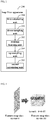
sampling unit 201 may perform the down sampling on the frame of input reconstructed image via a convolutional layer (referred to as a first convolutional layer, or a down-sampling convolutional layer) to obtain the feature maps of N channels. A kernel size, the number of channels and a stride of convolution of the convolutional layer are not limited in the embodiment of this disclosure. For example, the convolutional layer may be a 4×4 32-channel convolutional layer with a stride of convolution of (4, 4). - In order to reduce the number of pixels, down-sampling may be performed on the frame of input reconstructed image via the convolutional layer, in which the frame the reconstructed image is down-sampled from N1×N1 to (N1/4) × (N1/4), where, N1 is the number of pixels. For example, down-sampling is performed on a 64×64 image frame by using the above 4×4×32 convolutional layer, and 16×16 feature maps of 32 channels may be obtained, as shown in
FIG. 3 . Thus, via the first convolutional layer, it is possible to ensure that useful information is not lost and useless information is removed. - In one or some embodiments, the
residual learning unit 202 may perform the residual learning on input feature maps of N channels respectively via multiple residual blocks, to obtain feature maps of N channels respectively and output the feature maps of N channels respectively. With the multiple residual blocks, performance of restoration may be improved. - In one or some embodiments, four residual blocks may be used to balance a processing speed and performance, and each residual block may include three convolutional layers.
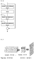
FIG. 4 is a schematic diagram of an embodiment of a residual block. As shown inFIG. 4 , the residual block may include a secondconvolutional layer 401, a thirdconvolutional layer 402 and a fourthconvolutional layer 403. The secondconvolutional layer 401 is configured to perform dimension increasing processing on input feature maps of N channels to obtain feature maps of M channels, M being greater than N; the thirdconvolutional layer 402 is configured to perform dimension reducing processing on the feature maps of M channels from the secondconvolutional layer 401 to obtain feature maps of N channels; and the fourthconvolutional layer 403 is configured to perform feature extraction on the feature maps of N channels from the thirdconvolutional layer 402 to obtain feature maps of N channels and output the feature maps of N channels. - Still taking the above N=32 as an example, the second
convolutional layer 401 may be a 1×1 192-channel convolutional layer, and via this convolutional layer, dimensions may be expanded; the thirdconvolutional layer 402 may be a 1×1 32-channel convolutional layer, and via this convolutional layer, dimensions may be reduced; and the fourthconvolutional layer 403 may be a 3×3 32-channel depthwise-separable convolutional layer, and via this convolutional layer, convolution parameters may be reduced. - In one or some embodiments, the up-
sampling unit 203 may perform the up sampling on input feature maps of N channels via a convolutional layer (referred to as a fifth convolutional layer) and an integration layer, to obtain an image of an original size of the above reconstructed image. - In an embodiment, the fifth convolutional layer may compress input feature maps of N channels to obtain feature maps of N channels, and the integration layer may integrate the feature maps of N channels from the fifth convolutional layer, combine them into an image, and take the image as the image of an original size of the reconstructed image.
- For example, the fifth convolutional layer may be a 3×3 4-channel convolutional layer, and the integration layer may be a pixel shuffle layer (emulation + permutation), which may integrate input 32×32 feature maps of 4 channels into 64×64 feature maps of 1 channel, as shown in
FIG. 5 , and the 64×64 feature map is a result of difference learnt by a neural network. - In one or some embodiments, as shown in
FIG. 2 , theloop filter apparatus 200 may further include a first calculatingunit 204 and asecond calculating unit 205. Thefirst calculating unit 204 is configured to divide the frame of input reconstructed image by a quantization step, and take a result of calculation as input of the down-sampling unit 201, and the second calculatingunit 205 is configured to multiply an image of an original size output by the up-sampling unit 203 by the quantization step, and take a result of calculation as the image of an original size and output the image of an original size. - In image and video compression, a large range of values are usually changed into a small range of values by using quantization. The quantization operation usually consists of two parts, namely forward quantization (FQ or Q) in an encoder and inverse quantization (IQ) in a decoder. And the quantization operation can be used to reduce the accuracy of image data after applying transformation (T). The following formula shows a usual example of a quantizer and an inverse quantizer:


QP Qstep QP Qstep QP Qstep QP Qstep QP Qstep 0 0.625 11 2.25 22 8 33 28 44 104 1 0.6875 12 2.5 23 9 34 32 45 112 2 0.8125 13 2.75 24 10 35 36 46 128 3 0.875 14 3.25 25 11 36 40 47 144 4 1 15 3.5 26 13 37 44 48 160 5 1.125 16 4 27 14 38 52 49 176 6 1.25 17 4.5 28 16 39 56 50 208 7 1.375 18 5 29 18 40 64 51 224 8 1.625 19 5.5 30 20 41 72 9 1.75 20 6.5 31 22 42 80 10 2 21 7 32 26 43 88 - Qstep obtained from QP may reduce a difference between videos encoded by different QPs. In the embodiment of this disclosure, the reconstructed image or frame is divided by Qstep before the downsampling, which may control blocking of different images at the same level, and in the embodiment of this disclosure, multiplication by Qstep is performed after the upsampling, which may restore pixel values. In this way, a CNN model may use video sequences of different QPs.
-
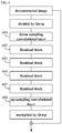
FIG. 6 is a schematic diagram of a network structure of theloop filter apparatus 200 of the embodiment of this disclosure. As shown inFIG. 6 , the reconstructed image is divided by Qstep and then output to a down-sampling convolutional layer 601. The down-sampling convolutional layer 601 performs down-sampling on input reconstructed image to obtain feature maps of N channels and outputs the feature maps of N channels to aresidual block 602. Theresidual block 602 performs residual learning on the feature maps of N channels to obtain feature maps of N channels and outputs the feature maps of N channels to aresidual block 603, theresidual block 603 performs the same processing as theresidual block 602 to obtain feature maps of N channels and outputs the feature maps of N channels to aresidual block 604, theresidual block 604 performs the same processing as theresidual block 602 to obtain feature maps of N channels and outputs the feature maps of N channels to aresidual block 605, theresidual block 605 performs the same processing as theresidual block 602 to obtain feature maps of N channels and outputs the feature maps of N channels to an up-sampling convolutional layer 606, and the up-sampling convolutional layer 606 performs up-sampling on input feature maps of N channels to obtain image of the original size of the reconstructed image and output the image of the original size, and the image of the original size is output after being multiplied by Qstep to obtain a filtering result. - In the embodiment of this disclosure, as described above, the
CNN filter 1032 may include theloop filtering apparatus 200, and furthermore, theCNN filter 1032 may include other components or assemblies, and the embodiment of this disclosure is not limited thereto. - In the embodiment of this disclosure, as described above, the above
loop filtering apparatus 200 may be used to process intra frames; however, this embodiment is not limited thereto. - It should be noted that the
loop filter apparatus 200 of the embodiment of this disclosure is only schematically described inFIG. 2 ; however, this disclosure is not limited thereto. For example, connection relationships between the modules or components may be appropriately adjusted, and furthermore, some other modules or components may be added, or some modules or components therein may be reduced. And appropriate variants may be made by those skilled in the art according to the above contents, without being limited to what is contained inFIG. 2 . - The image compression system of the embodiment of this disclosure carries out the functions of the loop filter by using a convolutional neural network, which may reduce a difference between a reconstructed frame and an original frame, reduce an amount of computation, and save processing time of the CNN
- The embodiment of this disclosure provides a loop filter apparatus.
FIG. 2 is a schematic diagram of theloop filter apparatus 200 of the embodiment of this disclosure, andFIG. 6 is a schematic diagram of a network structure of the loop filter apparatus of the embodiment of this disclosure. As the loop filter apparatus has been described in Embodiment 1 in detail, its contents are incorporated herein, and shall not be described herein any further. - With the loop filter apparatus of the embodiment of this disclosure, a convolutional neural network is used to carry out the functions of the loop filter, which may reduce a difference between a reconstructed frame and an original frame, reduce an amount of computation, and save processing time of the CNN
- The embodiment of this disclosure provides an image decoding apparatus.
FIG. 1 shows theimage decoding apparatus 103 of the embodiment of this disclosure. As theimage decoding apparatus 103 has been described in Embodiment 1 in detail, its contents are incorporated herein, and shall not be described herein any further. - With the image decoding apparatus of the embodiment of this disclosure, a convolutional neural network is used to carry out the functions of the loop filter, which may reduce a difference between a reconstructed frame and an original frame, reduce an amount of computation, and save processing time of the CNN
- The embodiment of this disclosure provides a loop filter method. As principles of the method for solving problems are similar to that of the
loop filter apparatus 200 in Embodiment 1 and has been described in Embodiment 1, reference may be made to the implementation of theloop filter apparatus 200 in Embodiment 1 for implementation of this method, with identical contents being going to be described herein any further. -
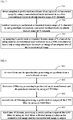
FIG. 7 is a schematic diagram of the loop filter method of the embodiment of this disclosure. As shown inFIG. 7 , the loop filter method includes: - 701: down sampling is performed on a frame of an input reconstructed image by using a convolutional layer (referred to as a first convolutional layer) to obtain feature maps of N channels;
- 702: residual learning is performed on input feature maps of N channels by using multiple successively connected residual blocks to obtain feature maps of N channels; and
- 703: up sampling is performed on input feature maps of N channels by using another convolutional layer (referred to as a fifth convolutional layer) and an integration layer to obtain an image of an original size of the reconstructed image.
- In the embodiment of this disclosure, reference may be made to the implementation of the units in
FIG. 2 in Embodiment 1 for implementations of the operations inFIG. 7 , which shall not be described herein any further. - In
operation 702 of the embodiment of this disclosure, each residual block may include three convolutional layers; wherein one convolutional layer (referred to as a second convolutional layer) may perform dimension increasing processing on input feature maps of N channels to obtain feature maps of M channels, M being greater than N, another convolutional layer (referred to as a third convolutional layer) may perform dimension reducing processing on the feature maps of M channels from the second convolutional layer to obtain feature maps of N channels, and the last convolutional layer (referred to as a fourth convolutional layer) may perform feature extraction on the feature maps of N channels from the third convolutional layer to obtain feature maps of N channels. A function relu may be included between the second convolutional layer and the third convolutional layer, and reference may be made to related techniques for principles and implementations of the function relu, which shall not be described herein any further. And furthermore, the fourth convolutional layer may be a depthwise-separable convolutional layer, and reference may be made to related techniques for principles and implementations thereof, which shall not be described herein any further. - In
operation 703 of the embodiment of this disclosure, the fifth convolutional layer may compress input feature maps of N channels to obtain feature maps of N channels, and the integration layer may integrate the feature maps of N channels from the fifth convolutional layer, combine them into an image, and take the image as the image of an original size of the reconstructed image. - In the embodiment of this disclosure, before performing the above-described downsampling, input reconstructed image frame may be divided by the quantization step, and after performing the above-described upsampling, the output of the upsampling may be multiplied by the quantization step, and a calculation result may be taken as the image of the original size and output.
- In the embodiment of this disclosure, the above reconstructed image frame may be an intra frame.
- With the loop filter method of the embodiment of this disclosure, a convolutional neural network is used to carry out the functions of the loop filter, which may reduce a difference between a reconstructed frame and an original frame, reduce an amount of computation, and save processing time of the CNN.
- The embodiment of this disclosure provides an image decoding method. As principles of the method for solving problems are similar to that of the
image decoding apparatus 103 in Embodiment 1 and has been described in Embodiment 1, reference may be made to the implementation of theimage decoding apparatus 103 in Embodiment 1 for implementation of this method, with identical contents being not going to be described herein any further. -
FIG. 8 is a schematic diagram of the image decoding method of the embodiment of this disclosure. As shown inFIG. 8 , the image decoding method includes: - 801: de-transform and de-quantization processing are performed on a received code stream;
- 802: first time of filtering processing is performed on de-transformed and de-quantized contents by using a CNN filter;
- 803: second time of filtering processing is performed on output of the CNN filter by using an SAO filter; and
- 804: third time of filtering processing is performed on output of the SAO filter by using an ALF filter, and a filtered image is taken as the reconstructed image and the reconstructed image is output.
- In the embodiment of this disclosure, the CNN filter includes the
loop filter apparatus 200 as described in Embodiment 1, which is used to carry out the loop filter method in Embodiment 3. As the apparatus and method have been described in embodiments 1 and 3, the contents thereof are incorporated herein, which shall not be described herein any further. - In the embodiment of this disclosure, reference may be made to related techniques for principles and implementations of the SAO filter and the ALF filter, which shall not be described herein any further.
- In the embodiment of this disclosure, intra prediction may be performed on the output after de-transform and de-quantization, and inter prediction may be performed on the output of the ALF filter according to a motion estimation result and a reference frame. In addition, motion estimation may be performed according to an input video frame and the above reference frame to obtain the above motion estimation result.
- With the image decoding method of the embodiment of this disclosure, a convolutional neural network is used to carry out the functions of the loop filter, which may reduce a difference between a reconstructed frame and an original frame, reduce an amount of computation, and save processing time of the CNN.
- The embodiment of this disclosure provides an image processing device, including the
image compression system 100 described in Embodiment 1, or theloop filter apparatus 200 described in Embodiment 1, or theimage decoding apparatus 103 described in Embodiment 3. - As the
image compression system 100, theloop filter apparatus 200 and theimage decoding apparatus 103 have been described in embodiments 1-3 in detail, the contents of which are incorporated herein, which shall not be described herein any further. -
FIG. 9 is a schematic diagram of the image processing device of the embodiment of this disclosure. As shown inFIG. 9 , animage processing device 900 may include a central processing unit (CPU) 901 and amemory 902, thememory 902 being coupled to thecentral processing unit 901. Thememory 902 may store various data, and furthermore, it may store a program for information processing, and execute the program under control of thecentral processing unit 901. - In one embodiment, functions of the
loop filter apparatus 200 or theimage decoding apparatus 103 may be integrated into thecentral processing unit 901. Thecentral processing unit 901 may be configured to carry out the method(s) as described in Embodiment(s) 4 and/or 5. - In another embodiment, the
loop filter apparatus 200 or theimage decoding apparatus 103 and thecentral processing unit 901 may be configured separately; for example, theloop filter apparatus 200 or theimage decoding apparatus 103 may be configured as a chip connected to thecentral processing unit 901, and the functions of theloop filter apparatus 200 or theimage decoding apparatus 103 are executed under the control of thecentral processing unit 901. - Furthermore, as shown in
FIG. 9 , the image processing device may include an input/output (I/O)device 903, and adisplay 904, etc.; wherein functions of the above components are similar to those in the related art, and shall not be described herein any further. It should be noted that the image processing device does not necessarily include all the components shown inFIG. 9 ; and furthermore, the image processing device may also include components not shown inFIG. 9 , and reference may be made to the related art. - An embodiment of this disclosure provides a computer readable program, which, when executed in an image processing device, will cause the image processing device to carry out the method(s) as described in Embodiment(s) 4 and/or 5.
- An embodiment of this disclosure provides a computer storage medium, including a computer readable program, which will cause an image processing device to carry out the method(s) as described in Embodiment(s) 4 and/or 5.
- The above apparatuses and methods of this disclosure may be implemented by hardware, or by hardware in combination with software. This disclosure relates to such a computer-readable program that when the program is executed by a logic device, the logic device is enabled to carry out the apparatus or components as described above, or to carry out the methods or steps as described above. The present disclosure also relates to a storage medium for storing the above program, such as a hard disk, a floppy disk, a CD, a DVD, and a flash memory, etc.
- The methods/apparatuses described with reference to the embodiments of this disclosure may be directly embodied as hardware, software modules executed by a processor, or a combination thereof. For example, one or more functional block diagrams and/or one or more combinations of the functional block diagrams shown in
FIGs. 1 and2 may either correspond to software modules of procedures of a computer program, or correspond to hardware modules. Such software modules may respectively correspond to the steps shown inFIGs. 7 and 8 . And the hardware module, for example, may be carried out by firming the soft modules by using a field programmable gate array (FPGA). - The soft modules may be located in an RAM, a flash memory, an ROM, an EPROM, and EEPROM, a register, a hard disc, a floppy disc, a CD-ROM, or any memory medium in other forms known in the art. A memory medium may be coupled to a processor, so that the processor may be able to read information from the memory medium, and write information into the memory medium; or the memory medium may be a component of the processor. The processor and the memory medium may be located in an ASIC. The soft modules may be stored in a memory of a mobile terminal, and may also be stored in a memory card of a pluggable mobile terminal. For example, if equipment (such as a mobile terminal) employs an MEGA-SIM card of a relatively large capacity or a flash memory device of a large capacity, the soft modules may be stored in the MEGA-SIM card or the flash memory device of a large capacity.
- One or more functional blocks and/or one or more combinations of the functional blocks in the drawings may be realized as a universal processor, a digital signal processor (DSP), an application-specific integrated circuit (ASIC), a field programmable gate array (FPGA) or other programmable logic devices, discrete gate or transistor logic devices, discrete hardware component or any appropriate combinations thereof carrying out the functions described in this application. And the one or more functional block diagrams and/or one or more combinations of the functional block diagrams in the drawings may also be realized as a combination of computing equipment, such as a combination of a DSP and a microprocessor, multiple processors, one or more microprocessors in communication combination with a DSP, or any other such configuration.
- This disclosure is described above with reference to particular embodiments. However, it should be understood by those skilled in the art that such a description is illustrative only, and not intended to limit the protection scope of the present disclosure. Various variants and modifications may be made by those skilled in the art according to the principle of the present disclosure, and such variants and modifications fall within the scope of the present disclosure.
Claims (10)
- A loop filter apparatus, characterized in that the loop filter apparatus comprises:a down-sampling unit configured to perform down sampling on a frame of an input reconstructed image to obtain feature maps of N channels;a residual learning unit configured to perform residual learning on input feature maps of N channels to obtain feature maps of N channels; andan up-sampling unit configured to perform up sampling on input feature maps of N channels to obtain an image of an original size of the reconstructed image.
- The loop filter apparatus according to claim 1, characterized in that the down-sampling unit performs the down sampling on frame of input reconstructed image via a first convolutional layer to obtain feature maps of N channels.
- The loop filter apparatus according to claim 1, characterized in that the residual learning unit performs the residual learning on input feature maps of N channels respectively via multiple residual blocks.
- The loop filter apparatus according to claim 3, characterized in that each residual block comprises:a second convolutional layer configured to perform dimension increasing processing on input feature maps of N channels to obtain feature maps of M channels, M being greater than N;a third convolutional layer configured to perform dimension reducing processing on the feature maps of M channels from the second convolutional layer to obtain feature maps of N channels; anda fourth convolutional layer configured to perform feature extraction on the feature maps of N channels from the third convolutional layer to obtain feature maps of N channels.
- The loop filter apparatus according to claim 4, characterized in that the fourth convolutional layer is a depthwise-separable convolutional layer.
- The loop filter apparatus according to claim 1, characterized in that the up-sampling unit performs the up sampling on input feature maps of N channels via a fifth convolutional layer and an integration layer,
the fifth convolutional layer compressing input feature maps of N channels to obtain feature maps of N channels,
and the integration layer integrating the feature maps of N channels from the fifth convolutional layer, combining them into an image, and taking the image as the image of an original size of the reconstructed image. - The loop filter apparatus according to claim 1, characterized in that the loop filter apparatus further comprises:a first calculating unit configured to divide the frame of input reconstructed image by a quantization step, and take a result of calculation as input of the down-sampling unit; anda second calculating unit configured to multiply an image of an original size output by the up-sampling unit by the quantization step, and take a result of calculation as the image of an original size and output the image of an original size.
- The loop filter apparatus according to claim 1, characterized in that the frame of the reconstructed image is an intra frame.
- An image decoding apparatus, characterized in that the image decoding apparatus comprises:a processing unit configured to perform de-transform and de-quantization processing on a received code stream;a convolutional neural networks (CNN) filtering unit configured to perform first time of filtering processing on output of the processing unit;a sample adaptive offset (SAO) filtering unit configured to perform second time of filtering processing on output of the CNN filtering unit; andan adaptive loop filter (ALF) filtering unit configured to perform third time of filtering processing on output of the SAO filtering unit, take a filtered image as the reconstructed image and output the reconstructed image;wherein the CNN filtering unit comprises a loop filter apparatus, and the loop filter apparatus is configured to:perform down sampling on a frame of an input reconstructed image to obtain feature maps of N channels;perform residual learning on input feature maps of N channels to obtain feature maps of N channels; andperform up sampling on input feature maps of N channels to obtain an image of an original size of the reconstructed image.
- The image decoding apparatus according to claim 9, characterized in that the image decoding apparatus further comprises:a first predicting unit configured to perform intra prediction on the output of the processing unit;a second predicting unit configured to perform inter prediction on the output of the ALF filtering unit according to a motion estimation result and a reference frame; anda motion estimating unit configured to perform motion estimation according to an input video frame and the reference frame, to obtain the motion estimation result and provide the motion estimation result to the second predicting unit.
Applications Claiming Priority (1)
| Application Number | Priority Date | Filing Date | Title |
|---|---|---|---|
| CN201910627550.9A CN112218097A (en) | 2019-07-12 | 2019-07-12 | Loop filter device and image decoding device |
Publications (1)
| Publication Number | Publication Date |
|---|---|
| EP3764651A1 true EP3764651A1 (en) | 2021-01-13 |
Family
ID=71016409
Family Applications (1)
| Application Number | Title | Priority Date | Filing Date |
|---|---|---|---|
| EP20178490.7A Withdrawn EP3764651A1 (en) | 2019-07-12 | 2020-06-05 | Loop filter apparatus and image decoding apparatus |
Country Status (4)
| Country | Link |
|---|---|
| US (1) | US20210012537A1 (en) |
| EP (1) | EP3764651A1 (en) |
| JP (1) | JP2021016150A (en) |
| CN (1) | CN112218097A (en) |
Cited By (3)
| Publication number | Priority date | Publication date | Assignee | Title |
|---|---|---|---|---|
| CN115209149A (en) * | 2022-06-22 | 2022-10-18 | 上海双深信息技术有限公司 | Deep learning coding and decoding network training method and device |
| US20230069030A1 (en) * | 2021-08-26 | 2023-03-02 | Sigmastar Technology Ltd. | Image processing device and image processing method |
| WO2024078404A1 (en) * | 2022-10-14 | 2024-04-18 | 维沃移动通信有限公司 | Feature map processing method and apparatus, and device |
Families Citing this family (21)
| Publication number | Priority date | Publication date | Assignee | Title |
|---|---|---|---|---|
| US12363350B2 (en) * | 2021-01-19 | 2025-07-15 | Alibaba Group Holding Limited | Neural network based in-loop filtering for video coding |
| CN112989992B (en) * | 2021-03-09 | 2023-12-15 | 阿波罗智联(北京)科技有限公司 | Target detection method and device, road side equipment and cloud control platform |
| CN113068031B (en) * | 2021-03-12 | 2021-12-07 | 天津大学 | Loop filtering method based on deep learning |
| CN113034455B (en) * | 2021-03-17 | 2023-01-10 | 清华大学深圳国际研究生院 | Method for detecting pockmarks of planar object |
| US12309364B2 (en) * | 2021-04-07 | 2025-05-20 | Beijing Dajia Internet Information Technology Co., Ltd. | System and method for applying neural network based sample adaptive offset for video coding |
| US12423878B2 (en) * | 2021-06-16 | 2025-09-23 | Tencent America LLC | Content-adaptive online training method and apparatus for deblocking in block-wise image compression |
| CN113497941A (en) * | 2021-06-30 | 2021-10-12 | 浙江大华技术股份有限公司 | Image filtering method, encoding method and related equipment |
| US12095988B2 (en) * | 2021-06-30 | 2024-09-17 | Lemon, Inc. | External attention in neural network-based video coding |
| US12603998B2 (en) * | 2021-07-07 | 2026-04-14 | Lemon Inc. | Configurable neural network model depth in neural network-based video coding |
| AU2022321329A1 (en) | 2021-08-06 | 2024-03-07 | Samsung Electronics Co., Ltd. | Device and method for ai-based filtering of image |
| EP4407994A4 (en) * | 2021-09-22 | 2025-12-17 | Sharp Kk | MOVING IMAGE ENCODING DEVICE AND MOVING IMAGE DECODING DEVICE |
| CN115883851A (en) * | 2021-09-28 | 2023-03-31 | 腾讯科技(深圳)有限公司 | Filtering, encoding and decoding methods and devices, computer readable medium and electronic equipment |
| CN119484817A (en) * | 2021-09-28 | 2025-02-18 | 腾讯科技(深圳)有限公司 | Filtering and encoding and decoding method, device, computer readable medium and electronic device |
| CN114125449B (en) * | 2021-10-26 | 2024-06-11 | 阿里巴巴创新公司 | Video processing method, system and computer readable medium based on neural network |
| CN114173130B (en) * | 2021-12-03 | 2023-02-10 | 电子科技大学 | Loop filtering method of deep neural network suitable for low bit rate condition |
| US12167047B2 (en) * | 2022-01-13 | 2024-12-10 | Tencent America LLC | Neural network-based deblocking filters |
| CN114513662B (en) * | 2022-04-19 | 2022-06-17 | 北京云中融信网络科技有限公司 | QP (quantization parameter) adaptive in-loop filtering method and system, electronic equipment and storage medium |
| CN120019663A (en) * | 2022-10-13 | 2025-05-16 | Oppo广东移动通信有限公司 | Depthwise Separable Convolution Based Convolutional Neural Network for Loop Filter of Video Encoder |
| CN118250463A (en) * | 2022-12-23 | 2024-06-25 | 维沃移动通信有限公司 | Image processing method, device and equipment |
| WO2025081379A1 (en) * | 2023-10-18 | 2025-04-24 | Guangdong Oppo Mobile Telecommunications Corp., Ltd. | Convolution and transformer based low complexity in-loop filter |
| CN119767016A (en) * | 2024-12-30 | 2025-04-04 | 中国电信股份有限公司技术创新中心 | Video compression method, device, computer readable medium and electronic device |
Citations (1)
| Publication number | Priority date | Publication date | Assignee | Title |
|---|---|---|---|---|
| US20190075301A1 (en) * | 2017-09-01 | 2019-03-07 | Apple Inc. | Machine learning video processing systems and methods |
Family Cites Families (4)
| Publication number | Priority date | Publication date | Assignee | Title |
|---|---|---|---|---|
| CN103843350A (en) * | 2011-10-14 | 2014-06-04 | 联发科技股份有限公司 | Loop filtering method and device |
| CN104282030A (en) * | 2013-07-12 | 2015-01-14 | 富士通株式会社 | Image compression device and method |
| KR102301232B1 (en) * | 2017-05-31 | 2021-09-10 | 삼성전자주식회사 | Method and apparatus for processing multiple-channel feature map images |
| WO2020146911A2 (en) * | 2019-05-03 | 2020-07-16 | Futurewei Technologies, Inc. | Multi-stage multi-reference bootstrapping for video super-resolution |
-
2019
- 2019-07-12 CN CN201910627550.9A patent/CN112218097A/en active Pending
-
2020
- 2020-06-05 EP EP20178490.7A patent/EP3764651A1/en not_active Withdrawn
- 2020-06-10 US US16/898,144 patent/US20210012537A1/en not_active Abandoned
- 2020-06-11 JP JP2020101771A patent/JP2021016150A/en active Pending
Patent Citations (1)
| Publication number | Priority date | Publication date | Assignee | Title |
|---|---|---|---|---|
| US20190075301A1 (en) * | 2017-09-01 | 2019-03-07 | Apple Inc. | Machine learning video processing systems and methods |
Non-Patent Citations (6)
| Title |
|---|
| "Test Model 5 of Versatile Video Coding (VTM 5)", no. n18371, 7 July 2019 (2019-07-07), XP030222341, Retrieved from the Internet <URL:http://phenix.int-evry.fr/mpeg/doc_end_user/documents/126_Geneva/wg11/w18371.zip w18371.docx> [retrieved on 20190707] * |
| "Working Draft 5 of Versatile Video Coding", no. n18370, 7 July 2019 (2019-07-07), XP030222340, Retrieved from the Internet <URL:http://phenix.int-evry.fr/mpeg/doc_end_user/documents/126_Geneva/wg11/w18370.zip w18370.docx> [retrieved on 20190707] * |
| LI Y ET AL: "CE13: Summary Report on Neural Network based Filter for Video Coding", no. JVET-N0033, 19 March 2019 (2019-03-19), XP030255433, Retrieved from the Internet <URL:http://phenix.int-evry.fr/jvet/doc_end_user/documents/14_Geneva/wg11/JVET-N0033-v1.zip JVET-N0033-v1.docx> [retrieved on 20190319] * |
| LUHANG XU (FUJITSU) ET AL: "Non-CE10: A CNN based in-loop filter for intra frame", no. JVET-O0157, 5 July 2019 (2019-07-05), XP030218728, Retrieved from the Internet <URL:http://phenix.int-evry.fr/jvet/doc_end_user/documents/15_Gothenburg/wg11/JVET-O0157-v2.zip JVET-O0157.docx> [retrieved on 20190705] * |
| LUHANG XU (FUJITSU) ET AL: "Non-CE10: A CNN based in-loop filter for intra frame", no. JVET-O0157, 5 July 2019 (2019-07-05), XP030218729, Retrieved from the Internet <URL:http://phenix.int-evry.fr/jvet/doc_end_user/documents/15_Gothenburg/wg11/JVET-O0157-v2.zip JVET-O0157.pptx> [retrieved on 20190705] * |
| Y-L HSIAO ET AL: "CE13-1.1: Convolutional neural network loop filter", no. JVET-N0110, 13 March 2019 (2019-03-13), XP030254669, Retrieved from the Internet <URL:http://phenix.int-evry.fr/jvet/doc_end_user/documents/14_Geneva/wg11/JVET-N0110-v1.zip JVET-N0110-v1.docx> [retrieved on 20190313] * |
Cited By (4)
| Publication number | Priority date | Publication date | Assignee | Title |
|---|---|---|---|---|
| US20230069030A1 (en) * | 2021-08-26 | 2023-03-02 | Sigmastar Technology Ltd. | Image processing device and image processing method |
| US12229850B2 (en) * | 2021-08-26 | 2025-02-18 | Sigmastar Technology Ltd. | Image processing device and image processing method |
| CN115209149A (en) * | 2022-06-22 | 2022-10-18 | 上海双深信息技术有限公司 | Deep learning coding and decoding network training method and device |
| WO2024078404A1 (en) * | 2022-10-14 | 2024-04-18 | 维沃移动通信有限公司 | Feature map processing method and apparatus, and device |
Also Published As
| Publication number | Publication date |
|---|---|
| JP2021016150A (en) | 2021-02-12 |
| US20210012537A1 (en) | 2021-01-14 |
| CN112218097A (en) | 2021-01-12 |
Similar Documents
| Publication | Publication Date | Title |
|---|---|---|
| EP3764651A1 (en) | Loop filter apparatus and image decoding apparatus | |
| CN109246422B (en) | Method and apparatus for processing cube face images | |
| CN113766249B (en) | Loop filtering method, device, equipment and storage medium in video coding and decoding | |
| US11375199B2 (en) | Interpolation filter for an inter prediction apparatus and method for video coding | |
| US8233060B2 (en) | Image data processing apparatus, image data processing method, and program | |
| CN112997504A (en) | Component-based loop filter | |
| US20210400306A1 (en) | Coding unit partitioning method, image coding/decoding method and apparatuses thereof | |
| CN114463453B (en) | Image reconstruction, encoding and decoding method and related device | |
| DE102018129344A1 (en) | Area adaptive, data efficient generation of partitioning decisions and mode decisions for video coding | |
| CN110830808A (en) | Video frame reconstruction method and device and terminal equipment | |
| CN113518227B (en) | Data processing method and system | |
| CN111083501A (en) | Video frame reconstruction method and device and terminal equipment | |
| KR101158345B1 (en) | Method and system for performing deblocking filtering | |
| WO2024222387A1 (en) | Coding method, decoding method, and apparatus | |
| CN111083478A (en) | Video frame reconstruction method and device and terminal equipment | |
| WO2010024907A1 (en) | Systems and methods for compression transmission and decompression of video codecs | |
| CN104506867A (en) | Sample adaptive offset parameter estimation method and device | |
| WO2024145988A1 (en) | Neural network-based in-loop filter | |
| Konstantinides et al. | Application of SVD based spatial filtering to video sequences | |
| WO2007060498A1 (en) | Method and system for filtering image data | |
| JP2844619B2 (en) | Digital filter for image signal | |
| JP2831139B2 (en) | Image signal decoding device | |
| JP3317982B2 (en) | Image signal decoding device | |
| WO2023133888A1 (en) | Image processing method and apparatus, remote control device, system, and storage medium | |
| US20250008129A1 (en) | Image Encoding Method, Apparatus, and Device |
Legal Events
| Date | Code | Title | Description |
|---|---|---|---|
| PUAI | Public reference made under article 153(3) epc to a published international application that has entered the european phase |
Free format text: ORIGINAL CODE: 0009012 |
|
| STAA | Information on the status of an ep patent application or granted ep patent |
Free format text: STATUS: THE APPLICATION HAS BEEN PUBLISHED |
|
| AK | Designated contracting states |
Kind code of ref document: A1 Designated state(s): AL AT BE BG CH CY CZ DE DK EE ES FI FR GB GR HR HU IE IS IT LI LT LU LV MC MK MT NL NO PL PT RO RS SE SI SK SM TR |
|
| AX | Request for extension of the european patent |
Extension state: BA ME |
|
| STAA | Information on the status of an ep patent application or granted ep patent |
Free format text: STATUS: THE APPLICATION IS DEEMED TO BE WITHDRAWN |
|
| 18D | Application deemed to be withdrawn |
Effective date: 20210714 |