EP3764648A1 - Motion estimation method and device for video, terminal and storage medium - Google Patents
Motion estimation method and device for video, terminal and storage medium Download PDFInfo
- Publication number
- EP3764648A1 EP3764648A1 EP19764644.1A EP19764644A EP3764648A1 EP 3764648 A1 EP3764648 A1 EP 3764648A1 EP 19764644 A EP19764644 A EP 19764644A EP 3764648 A1 EP3764648 A1 EP 3764648A1
- Authority
- EP
- European Patent Office
- Prior art keywords
- point
- prediction unit
- search
- distortion cost
- motion vector
- Prior art date
- Legal status (The legal status is an assumption and is not a legal conclusion. Google has not performed a legal analysis and makes no representation as to the accuracy of the status listed.)
- Pending
Links
- 238000000034 method Methods 0.000 title claims abstract description 88
- 239000013598 vector Substances 0.000 claims abstract description 385
- 238000010845 search algorithm Methods 0.000 claims abstract description 103
- 238000004364 calculation method Methods 0.000 claims description 12
- 238000012937 correction Methods 0.000 claims description 6
- 229910003460 diamond Inorganic materials 0.000 description 42
- 239000010432 diamond Substances 0.000 description 42
- 238000010586 diagram Methods 0.000 description 16
- 238000005516 engineering process Methods 0.000 description 13
- 238000013507 mapping Methods 0.000 description 12
- 230000006870 function Effects 0.000 description 11
- 238000012545 processing Methods 0.000 description 8
- 238000004891 communication Methods 0.000 description 5
- 238000003672 processing method Methods 0.000 description 5
- 238000001514 detection method Methods 0.000 description 4
- 230000003287 optical effect Effects 0.000 description 4
- 238000007726 management method Methods 0.000 description 3
- 230000001133 acceleration Effects 0.000 description 2
- 230000006835 compression Effects 0.000 description 2
- 238000007906 compression Methods 0.000 description 2
- 238000013500 data storage Methods 0.000 description 2
- 238000001914 filtration Methods 0.000 description 2
- 230000005484 gravity Effects 0.000 description 2
- 238000013139 quantization Methods 0.000 description 2
- 230000005236 sound signal Effects 0.000 description 2
- 230000005540 biological transmission Effects 0.000 description 1
- 238000006243 chemical reaction Methods 0.000 description 1
- 238000007599 discharging Methods 0.000 description 1
- 238000006073 displacement reaction Methods 0.000 description 1
- 230000000694 effects Effects 0.000 description 1
- 238000012905 input function Methods 0.000 description 1
- 239000004973 liquid crystal related substance Substances 0.000 description 1
- 230000007774 longterm Effects 0.000 description 1
- 238000010295 mobile communication Methods 0.000 description 1
- 238000012986 modification Methods 0.000 description 1
- 230000004048 modification Effects 0.000 description 1
- 238000012544 monitoring process Methods 0.000 description 1
- 230000002093 peripheral effect Effects 0.000 description 1
- 238000011160 research Methods 0.000 description 1
- 239000007787 solid Substances 0.000 description 1
- 230000003068 static effect Effects 0.000 description 1
- 238000010897 surface acoustic wave method Methods 0.000 description 1
- 230000000007 visual effect Effects 0.000 description 1
Images






Classifications
-
- H—ELECTRICITY
- H04—ELECTRIC COMMUNICATION TECHNIQUE
- H04N—PICTORIAL COMMUNICATION, e.g. TELEVISION
- H04N19/00—Methods or arrangements for coding, decoding, compressing or decompressing digital video signals
- H04N19/50—Methods or arrangements for coding, decoding, compressing or decompressing digital video signals using predictive coding
- H04N19/503—Methods or arrangements for coding, decoding, compressing or decompressing digital video signals using predictive coding involving temporal prediction
- H04N19/51—Motion estimation or motion compensation
- H04N19/523—Motion estimation or motion compensation with sub-pixel accuracy
-
- H—ELECTRICITY
- H04—ELECTRIC COMMUNICATION TECHNIQUE
- H04N—PICTORIAL COMMUNICATION, e.g. TELEVISION
- H04N19/00—Methods or arrangements for coding, decoding, compressing or decompressing digital video signals
- H04N19/10—Methods or arrangements for coding, decoding, compressing or decompressing digital video signals using adaptive coding
- H04N19/102—Methods or arrangements for coding, decoding, compressing or decompressing digital video signals using adaptive coding characterised by the element, parameter or selection affected or controlled by the adaptive coding
- H04N19/119—Adaptive subdivision aspects, e.g. subdivision of a picture into rectangular or non-rectangular coding blocks
-
- H—ELECTRICITY
- H04—ELECTRIC COMMUNICATION TECHNIQUE
- H04N—PICTORIAL COMMUNICATION, e.g. TELEVISION
- H04N19/00—Methods or arrangements for coding, decoding, compressing or decompressing digital video signals
- H04N19/10—Methods or arrangements for coding, decoding, compressing or decompressing digital video signals using adaptive coding
- H04N19/134—Methods or arrangements for coding, decoding, compressing or decompressing digital video signals using adaptive coding characterised by the element, parameter or criterion affecting or controlling the adaptive coding
- H04N19/146—Data rate or code amount at the encoder output
- H04N19/147—Data rate or code amount at the encoder output according to rate distortion criteria
-
- H—ELECTRICITY
- H04—ELECTRIC COMMUNICATION TECHNIQUE
- H04N—PICTORIAL COMMUNICATION, e.g. TELEVISION
- H04N19/00—Methods or arrangements for coding, decoding, compressing or decompressing digital video signals
- H04N19/10—Methods or arrangements for coding, decoding, compressing or decompressing digital video signals using adaptive coding
- H04N19/169—Methods or arrangements for coding, decoding, compressing or decompressing digital video signals using adaptive coding characterised by the coding unit, i.e. the structural portion or semantic portion of the video signal being the object or the subject of the adaptive coding
- H04N19/17—Methods or arrangements for coding, decoding, compressing or decompressing digital video signals using adaptive coding characterised by the coding unit, i.e. the structural portion or semantic portion of the video signal being the object or the subject of the adaptive coding the unit being an image region, e.g. an object
- H04N19/176—Methods or arrangements for coding, decoding, compressing or decompressing digital video signals using adaptive coding characterised by the coding unit, i.e. the structural portion or semantic portion of the video signal being the object or the subject of the adaptive coding the unit being an image region, e.g. an object the region being a block, e.g. a macroblock
-
- H—ELECTRICITY
- H04—ELECTRIC COMMUNICATION TECHNIQUE
- H04N—PICTORIAL COMMUNICATION, e.g. TELEVISION
- H04N19/00—Methods or arrangements for coding, decoding, compressing or decompressing digital video signals
- H04N19/50—Methods or arrangements for coding, decoding, compressing or decompressing digital video signals using predictive coding
- H04N19/503—Methods or arrangements for coding, decoding, compressing or decompressing digital video signals using predictive coding involving temporal prediction
- H04N19/51—Motion estimation or motion compensation
-
- H—ELECTRICITY
- H04—ELECTRIC COMMUNICATION TECHNIQUE
- H04N—PICTORIAL COMMUNICATION, e.g. TELEVISION
- H04N19/00—Methods or arrangements for coding, decoding, compressing or decompressing digital video signals
- H04N19/50—Methods or arrangements for coding, decoding, compressing or decompressing digital video signals using predictive coding
- H04N19/503—Methods or arrangements for coding, decoding, compressing or decompressing digital video signals using predictive coding involving temporal prediction
- H04N19/51—Motion estimation or motion compensation
- H04N19/513—Processing of motion vectors
-
- H—ELECTRICITY
- H04—ELECTRIC COMMUNICATION TECHNIQUE
- H04N—PICTORIAL COMMUNICATION, e.g. TELEVISION
- H04N19/00—Methods or arrangements for coding, decoding, compressing or decompressing digital video signals
- H04N19/50—Methods or arrangements for coding, decoding, compressing or decompressing digital video signals using predictive coding
- H04N19/503—Methods or arrangements for coding, decoding, compressing or decompressing digital video signals using predictive coding involving temporal prediction
- H04N19/51—Motion estimation or motion compensation
- H04N19/53—Multi-resolution motion estimation; Hierarchical motion estimation
-
- H—ELECTRICITY
- H04—ELECTRIC COMMUNICATION TECHNIQUE
- H04N—PICTORIAL COMMUNICATION, e.g. TELEVISION
- H04N19/00—Methods or arrangements for coding, decoding, compressing or decompressing digital video signals
- H04N19/50—Methods or arrangements for coding, decoding, compressing or decompressing digital video signals using predictive coding
- H04N19/503—Methods or arrangements for coding, decoding, compressing or decompressing digital video signals using predictive coding involving temporal prediction
- H04N19/51—Motion estimation or motion compensation
- H04N19/567—Motion estimation based on rate distortion criteria
-
- H—ELECTRICITY
- H04—ELECTRIC COMMUNICATION TECHNIQUE
- H04N—PICTORIAL COMMUNICATION, e.g. TELEVISION
- H04N19/00—Methods or arrangements for coding, decoding, compressing or decompressing digital video signals
- H04N19/50—Methods or arrangements for coding, decoding, compressing or decompressing digital video signals using predictive coding
- H04N19/503—Methods or arrangements for coding, decoding, compressing or decompressing digital video signals using predictive coding involving temporal prediction
- H04N19/51—Motion estimation or motion compensation
- H04N19/57—Motion estimation characterised by a search window with variable size or shape
Definitions
- This disclosure relates to the technical field of video compression, and in particular, to a video motion estimation method and apparatus, a terminal, and a storage medium.
- the inter-frame prediction is mainly to predict a pixel of the current image by using correlation of time domain of the video and using a pixel of an adjacent encoded image, so that the time domain of the video is not redundant.
- the inter-frame prediction part of video encoding mainly uses a block-based motion compensation technology.
- a principle is to find an optimal matching block in the previously encoded image for each pixel block (that is, a prediction unit) of the current image. This process is referred to as motion estimation (ME).
- An image used for prediction is referred to as a reference image, and displacement of a reference block in the reference image to the current pixel block in the current image is referred to as a motion vector (MV).
- the image frames are first divided into prediction units of modes such as 2N ⁇ 2N, 2N ⁇ N, N ⁇ 2N, 2N ⁇ nU, 2N ⁇ nD, nL ⁇ 2N, nR ⁇ 2N, or the like through an inter-frame prediction unit (PU). Then, a unified processing method is adopted for all prediction units. After a starting search point of each prediction unit is determined, the starting search point is used as the center, and a point with minimum rate-distortion cost is found within the search range.
- PU inter-frame prediction unit
- a location of the point with the minimum rate-distortion cost of each prediction unit is used as a motion vector corresponding to each prediction unit, and subsequent operations such as sub-pixel motion compensation are performed on the image frame according to the motion vector corresponding to each prediction unit.
- the inventor of this disclosure found that, because the same processing method is uniformly used for all prediction units in the related art, a new independent search is performed on each prediction unit. For example, for all the prediction units, the search method with the same complexity is used, causing an inflexible process of performing motion estimation on the video and low efficiency of motion estimation.
- a video motion estimation method is provided.
- a video motion estimation method including:
- a video motion estimation apparatus including:
- a terminal including a memory and one or more processors, the memory storing a computer-readable instruction, the computer-readable instruction, when executed by the processor, causing the one or more processors to perform the following operations:
- Embodiments of this disclosure provide a video motion estimation method, apparatus, and system.
- FIG. 1 is a schematic diagram of a scenario of a video motion estimation system according to an embodiment of this disclosure.
- the video motion estimation system may include a video motion estimation apparatus.
- the video motion estimation apparatus may be specifically integrated into a terminal such as a tablet computer, a mobile phone, a notebook computer, a desktop computer, a television, or the like that has a storage unit, is equipped with a microprocessor, and has computing capability, which is mainly configured to divide image frames in a video into a plurality of prediction units, and divide the plurality of prediction units into a first type prediction unit and a second type prediction unit.
- the video may be obtained locally from the terminal or downloaded from a server.
- the prediction unit may include a plurality of prediction units such as a prediction unit A, a prediction unit B, a prediction unit C, a prediction unit D, a prediction unit E, a prediction unit F, and the like.
- the first type prediction unit may include a plurality of prediction units such as a prediction unit A, a prediction unit B, a prediction unit C, and the like.
- the second type prediction unit may include a plurality of prediction units such as a prediction unit D, a prediction unit E, a prediction unit F, and the like.
- a motion vector of the first type prediction unit is obtained according to a first search algorithm
- a motion vector of the second type prediction unit is obtained according to a second search algorithm.
- a polygonal model may be obtained, and a current motion vector of the second type prediction unit may be obtained by moving the polygonal model.
- the polygonal model may be a diamond model or a hexagonal model.
- the video motion estimation system may further include a server, and the video motion estimation apparatus may download the video from the server.
- the video motion estimation apparatus may send a video obtaining request to the server, and receive a video file about the video fed back by the server based on the video obtaining request.
- the schematic diagram of the scenario of the video motion estimation system shown in FIG. 1 is only an example.
- the video motion estimation system and scenario described in the embodiments of this disclosure are intended to describe the technical solutions in the embodiments of this disclosure more clearly, and do not constitute a limitation on the technical solutions provided in the embodiments of this disclosure.
- a person skilled in the art may know that, with the evolution of the video motion estimation system and emergence of new business scenarios, the technical solutions provided in the embodiments of this disclosure are also applicable to similar technical problems.
- a video motion estimation apparatus is to be described.
- the video motion estimation apparatus may be specifically integrated in a terminal such as a computer, a mobile phone, a television, or the like that has a storage unit, is equipped with a microprocessor, and has computing capability.
- a video motion estimation method including: dividing image frames in a video into a plurality of prediction units, and dividing the plurality of prediction units into a first type prediction unit and a second type prediction unit; obtaining a motion vector of the first type prediction unit according to a first search algorithm, and obtaining a motion vector of the second type prediction unit according to a second search algorithm; and performing sub-pixel motion estimation on the image frame according to the motion vector of the first type prediction unit and the motion vector of the second type prediction unit.
- FIG. 2 is a schematic flowchart of a video motion estimation method according to a first embodiment of this disclosure.
- the video motion estimation method may include the following operations.
- step S101 image frames in a video are divided into a plurality of prediction units, and the plurality of prediction units are divided into a first type prediction unit and a second type prediction unit.
- the video motion estimation apparatus may obtain a video from the local or the server.
- inter-frame prediction encoding needs to be performed on the video.
- motion estimation needs to be performed on each image frame in the video.
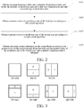
- the image frame in the video may be divided into a plurality of prediction units such as 2N ⁇ 2N, 2N ⁇ N, N ⁇ 2N, 2N ⁇ nU, 2N ⁇ nD, nL ⁇ 2N, and nR ⁇ 2N by using an inter-frame prediction unit PU. As shown in FIG.
- 2N ⁇ 2N, 2N ⁇ N, and N ⁇ 2N are prediction units in a symmetric mode.
- the 2N ⁇ N prediction unit includes a dividing block with an index of 0 and an index of 1 divided by a ratio of 1:1 up and down.
- 2N ⁇ nU, 2N ⁇ nD, nL ⁇ 2N, and nR ⁇ 2N are prediction units in an asymmetric mode.
- the 2N ⁇ nD prediction unit includes a dividing block with an index of 0 and an index of 1 divided by a ratio of 3:1 up and down.
- the prediction unit of the asymmetric mode adopts a search method with the same complexity as the prediction unit of the symmetric mode, therefore, in order to improve flexibility and efficiency of performing motion estimation on the video, after a plurality of prediction units are obtained, the plurality of prediction units may be divided into a first type prediction unit and a second type prediction unit.
- the first type prediction unit may include prediction units such as 2N ⁇ 2N, 2N ⁇ N, N ⁇ 2N, and the like in the symmetric mode
- the second type prediction unit may include prediction units such as 2N ⁇ nU, 2N ⁇ nD, nL ⁇ 2N, nR ⁇ 2N, and the like in the asymmetric mode.
- the method for dividing the prediction unit and the method for dividing the first type prediction unit and the second type prediction unit may be flexibly set according to actual needs, and specific content is not limited herein.
- first and second used in the embodiments of this disclosure are merely for the purpose of description and cannot be construed as indicating or implying importance.
- the first type prediction unit and the second type prediction unit both are prediction units.
- the first type prediction unit corresponds to one type of prediction unit
- the second type prediction unit corresponds to another type of prediction unit. It does not indicate that the first type prediction unit is more important than the second type prediction unit, and the like.
- step S 102 a motion vector of the first type prediction unit is obtained according to a first search algorithm.
- the video motion estimation apparatus may respectively use different search algorithms to search the motion vector of the prediction unit.
- the motion vector of the first type prediction unit may be obtained according to the first search algorithm.
- a motion vector of the second type prediction unit is obtained according to a second search algorithm.
- the first search algorithm is inconsistent with the second search algorithm, which are to be described in detail below.
- the operation of obtaining a motion vector of the first type prediction unit according to a first search algorithm may include:
- the video motion estimation apparatus determines a starting search point (that is, the second starting search point) in the following manner.
- the video motion estimation apparatus may obtain the second candidate starting search point corresponding to the first type prediction unit through advanced motion vector prediction (AMVP).
- AMVP advanced motion vector prediction
- the AMVP technology is mainly to use the correlation between motion vectors in space domain and time domain to establish a list of candidate prediction MVs for the current prediction unit.
- There is a plurality of candidate prediction MVs in the list and the video motion estimation apparatus may select the second candidate starting search point from the list of the plurality of candidate prediction MVs.
- the video motion estimation apparatus may also obtain a second candidate starting search point corresponding to the first type prediction unit by using a Merge mode.
- the video motion estimation apparatus may calculate rate-distortion cost of each second candidate starting search point, and set a second candidate starting search point with the minimum rate-distortion cost as the second starting search point, that is, the second starting search point is a finally determined starting search point corresponding to the first type prediction unit.
- Each rate-distortion cost below may be calculated by referring to the formula.
- the video motion estimation apparatus specifically searches an undetermined point (that is, a second undetermined point) within the search window range in the following manner.
- the video motion estimation apparatus may perform searching by using a diamond template, a square template, or the like.
- the diamond template is used as an example, and the second starting search point is used as a center of the diamond template.
- a search step size of 1 according to the diamond template shown in FIG. 4 , a plurality of second candidate points are obtained, according to a second preset increasing step size, within a search window range centered on the second starting search point.
- the second preset increasing step size may be a step size increasing by an integer power of 2, that is, from the search step size of 1, and searching is performed with the search step sizes of 2, 4, and 8 in turn, to obtain a plurality of second candidate points.
- the second candidate points may be vertexes of the diamond template corresponding to each search step size, a midpoint between the two vertexes, and the like, for example, a location of a five-pointed star marked in FIG. 4 .
- a corresponding search window range is an inner ring region of the diamond template corresponding to the search step size 8.
- a corresponding search window range is an inner ring region of the diamond template corresponding to the search step size 16, and so on.
- the rate-distortion cost of each second candidate point is calculated, the point with the minimum rate-distortion cost is selected from the plurality of second candidate points, and the point with the minimum rate-distortion cost in the plurality of second candidate points is set as the second undetermined point.
- two-point searching is performed around the undetermined point, which may be performed specifically as follows.
- the video motion estimation apparatus may determine whether the search step size corresponding to the second undetermined point is the second preset step size, and the second preset step size may be flexibly set according to actual needs.
- the second preset step size may be set to 1, that is, when the search step size corresponding to the second undetermined point is 1, a second supplementary point not searched around each point corresponding to the second preset step size may be obtained, and the second supplementary point may include one or more points, as shown in FIG. 5 .
- vertexes corresponding to the diamond with the search step size of 1 are four points of 2, 4, 5, and 7 if the search step size corresponding to the obtained second undetermined point is 1.
- the obtained second undetermined point with the minimum rate-distortion cost is a location of 2
- two points of A and B are supplemented at the location of 2
- the two points of A and B may be set as second supplementary points.
- the obtained second undetermined point with the minimum rate-distortion cost is a location of 4
- two points of C and E are supplemented at the location of 4
- the two points of C and E may be set as second supplementary points.
- the obtained second undetermined point with the minimum rate-distortion cost is a location of 5, then two points of D and F are supplemented at the location of 5, and the two points of D and F may be set as second supplementary points. If the obtained second undetermined point with the minimum rate-distortion cost is a location of 7, then two points of G and H are supplemented at the location of 7, and the two points of G and H may be set as second supplementary points.
- the point with the minimum rate-distortion cost may be selected from the second supplementary point and the second undetermined point in a specific manner as follows.
- the video motion estimation apparatus may calculate rate-distortion cost of each second supplementary point, compare the rate-distortion cost of the second supplementary point with the rate-distortion cost of the second undetermined point, and determine whether the point with the minimum rate-distortion cost in the second supplementary point and the second undetermined point is the second undetermined point.
- a location of the second undetermined point is set as the motion vector of the first type prediction unit in a case that the point with the minimum rate-distortion cost in the second undetermined point and the second supplementary point is the second undetermined point.
- the location of the point with the minimum rate-distortion cost in the second undetermined point and the second supplementary point is set as the motion vector of the first type prediction unit in a case that the point with the minimum rate-distortion cost in the second undetermined point and the second supplementary point is not the second undetermined point.
- the operation of setting a location of the second undetermined point as the motion vector of the first type prediction unit may include:
- the video motion estimation apparatus may correct the motion vector of the currently searched first type prediction unit according to the motion vector of the searched prediction unit in the image frame. Specifically, in the process of searching the motion vector of each prediction unit, the video motion estimation apparatus may store the motion vector of the searched prediction unit, and may generate a mapping relationship between a prediction unit identifier and the motion vector.
- the video motion estimation apparatus may obtain a mapping relationship corresponding to the searched prediction unit identifier, obtain the motion vector of the searched prediction unit in the image frame according to the mapping relationship, and calculate the second target rate-distortion cost of the corresponding location of the first type prediction unit according to the motion vector of the searched prediction unit. For example, a corresponding location may be determined according to the motion vector of the searched prediction unit, the rate-distortion cost of the corresponding location is calculated, and the rate-distortion cost of the corresponding location obtained through calculation is set as the second target rate-distortion cost. Then, the rate-distortion cost of the second undetermined point may be compared with the second target rate-distortion cost.
- the motion vector of the searched prediction unit is set as the motion vector of the first type prediction unit, that is, the motion vector of the first type prediction unit is corrected to the motion vector of the searched prediction unit.
- the location of the second undetermined point is set as the motion vector of the first type prediction unit in a case that the rate-distortion cost of the second undetermined point is less than or equal to the second target rate-distortion cost.
- the searched prediction unit may include one or more prediction units, which may include one or more prediction units of the first type prediction unit in the image frame, or may include one or more prediction units of the second type prediction unit in the image frame, or may include both one or more prediction units of the first type prediction unit in the image frame and one or more prediction units of the second type prediction unit in the image frame, and so on.
- the searched prediction unit may also include one or more motion vectors.
- the motion vector of the N ⁇ 2N prediction unit may be corrected by using the motion vectors of the 2N ⁇ 2N prediction unit and the 2N ⁇ N prediction unit.
- the second type prediction unit includes a third dividing block and a fourth dividing block, and the operation of obtaining a second candidate starting search point corresponding to the first type prediction unit, calculating rate-distortion cost of each second candidate starting search point, and setting the second candidate starting search point with the minimum rate-distortion cost as a second starting search point may include:
- the first type prediction unit may include a third dividing block with an index of 0 and a fourth dividing block with an index of 1.
- the video motion estimation apparatus may separately search for the motion vectors of the third dividing block and the fourth dividing block in the first type prediction unit.
- the motion vector of the searched third dividing block may be used for instructing the search process of the current fourth dividing block, that is, a location corresponding to the motion vector of the searched third dividing block may be used as one of the candidate starting search points of the current fourth dividing block.
- a location corresponding to the motion vector of the searched fourth dividing block is used as one of the candidate starting search points of the current third dividing block, and the location corresponding to the motion vector of the searched third dividing block is to be used as one of the starting search points of the current fourth dividing block, for example.
- the video motion estimation apparatus may obtain at least one second candidate starting search point corresponding to the fourth dividing block in the first type prediction unit through the AMVP technology, and determine whether the third dividing block in the first type prediction unit has been searched, that is, determine whether the third dividing block in the first type prediction unit has been predicted.
- a prediction result of the third dividing block is obtained.
- the prediction result may be the motion vector of the third dividing block.
- rate-distortion cost of the location of the third dividing block may be calculated according to the prediction result of the third dividing block, that is, the rate-distortion cost of the location of the third dividing block may be calculated according to the motion vector of the third dividing block.
- a corresponding location may be determined according to the motion vector of the third dividing block, the rate-distortion cost of the corresponding location is calculated, and the rate-distortion cost of the corresponding location obtained through calculation is set as the rate-distortion cost of the location of the third dividing block.
- the rate-distortion cost of each second candidate starting search point is calculated, the point with the minimum rate-distortion cost in at least one second candidate starting search point and the third dividing block is set as a starting search point of the fourth dividing block in the first type prediction unit, and the starting search point of the fourth dividing block is set as the second starting search point, so as to perform the operation of obtaining, according to a second preset increasing step size, a plurality of second candidate points within the search window range centered on the second starting search point, calculating rate-distortion cost of each second candidate point, and selecting a point with the minimum rate-distortion cost from the plurality of second candidate points, to obtain a second undetermined point.
- the 2N ⁇ N prediction unit is used as an example. Assuming that a dividing block with the index of 0 in the 2N ⁇ N prediction unit has been predicted, in this case, when a dividing block with the index of 1 in the 2N ⁇ N prediction unit is predicted, a location of the motion vector in the prediction result corresponding to the dividing block with the index of 0 may be used as one of locations of the candidate starting search point of the dividing block with the index of 1, so that the point with the minimum rate-distortion cost may be selected as the starting search point from the candidate starting search points. In this way, the starting search point is closer to an optimal location for motion estimation, and may exit the search process faster.
- the video motion estimation method may further include:
- the video motion estimation apparatus may determine whether the search step size corresponding to the second undetermined point is within a third preset step size threshold range, where the third preset step size threshold range may be flexibly set according to actual needs.
- a distance from the point with the minimum rate-distortion cost to a center of the search window range may be obtained to determine whether the distance is within the first preset distance threshold range.
- the preset distance threshold range may be flexibly set according to actual needs.
- the first preset distance threshold range may be greater than or equal to 5, and less than or equal to 8.
- Searching is performed according to a preset interval step size within a preset range centered on the second undetermined point in a case that the search step size corresponding to the second undetermined point is within a third preset step size threshold range (or the distance from the point with the minimum rate-distortion cost to the center of the search window range is within the first preset distance threshold range), to obtain a plurality of search points.
- the preset range and the preset interval step size may be flexibly set according to actual needs, and a specific value is not limited herein.
- the preset interval step size may be set to 5 steps for each row and column. As shown in FIG.
- FIG. 6 is merely a partial schematic diagram of searching within the search window range according to the preset interval step size.
- the search window range may be flexibly set according to actual needs, for example, may be set to 128 rows 128 columns.
- rate-distortion cost of each search point is calculated, the point with the minimum rate-distortion cost in the second undetermined point and the plurality of search points is used as the second starting search point, and the operation of obtaining, according to the second preset increasing step size, a plurality of second candidate points within the search window range centered on the second starting search point, calculating the rate-distortion cost of each second candidate point, and selecting the point with the minimum rate-distortion cost from the plurality of second candidate points, to obtain a second undetermined point is performed.
- the video motion estimation method may further include: using the second undetermined point as the second starting search point, and performing the operation of obtaining, according to the second preset increasing step size, a plurality of second candidate points within the search window range centered on the second starting search point, calculating the rate-distortion cost of each second candidate point, and selecting the point with the minimum rate-distortion cost from the plurality of second candidate points, to obtain a second undetermined point in a case that a search step size corresponding to the second undetermined point is within a fourth preset step size threshold range.
- the video motion estimation apparatus may determine whether the search step size corresponding to the second undetermined point is within the fourth step size threshold range, where the fourth preset step size threshold range may be flexibly set according to actual needs.
- a distance from the point with the minimum rate-distortion cost to a center of the search window range may be obtained to determine whether the distance is within a second preset distance threshold range.
- the second preset distance threshold range may be flexibly set according to actual needs, for example, may be greater than 1 and less than 5.
- the second undetermined point is used as the second starting search point, and the operation of obtaining, according to the second preset increasing step size, a plurality of second candidate points within the search window range centered on the second starting search point, calculating the rate-distortion cost of each second candidate point, and selecting the point with the minimum rate-distortion cost from the plurality of second candidate points, to obtain a second undetermined point is performed in a case that a search step size corresponding to the second undetermined point is within the fourth preset step size threshold range (or a distance from the point with the minimum rate-distortion cost to the center of the search window range is within the first preset distance threshold range).
- step S103 a motion vector of the second type prediction unit is obtained according to a second search algorithm.
- the video motion estimation apparatus may obtain the motion vector of the second type prediction unit by using the second search algorithm.
- the operation of obtaining a motion vector of the second type prediction unit according to a second search algorithm may include: obtaining a polygonal model according to the second search algorithm, and obtaining a current motion vector of the second type prediction unit by moving the polygonal model; and obtaining a motion vector of a searched prediction unit in an image frame, and correcting the current motion vector according to the motion vector of the searched prediction unit, to obtain the motion vector of the second type prediction unit.
- the operation of obtaining a polygonal model according to the second search algorithm, and obtaining a current motion vector of the second type prediction unit by moving the polygonal model may include:
- the video motion estimation apparatus may obtain a first candidate starting search point corresponding to the second type prediction unit through the AMVP technology, select a first starting search point from the first candidate starting search point, then perform searching with the first starting search point as the center of a diamond template or a square template to obtain a plurality of first candidate points, and select a first undetermined point from the plurality of first candidate points.
- the video motion estimation apparatus may determine whether the search step size corresponding to the first undetermined point is within the first preset step size threshold range, where the first preset step size threshold range may be flexibly set according to actual needs.
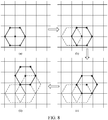
- a search step size of the first undetermined point is within the first preset step size threshold range, a polygonal model is obtained, where the polygonal model may be quadrilateral, hexagonal, or the like.
- the video motion estimation apparatus may obtain the first target point according to the polygonal model. For example, the video motion estimation apparatus may calculate rate-distortion cost of locations of the center of the polygonal model and each vertex, and set the point with the minimum rate-distortion cost in the center of the polygonal model and each vertex as the first target point.
- the video motion estimation apparatus may determine whether the first target point is consistent with the first undetermined point. When the first target point is inconsistent with the first undetermined point, it indicates that the obtained first target point may not be the optimal point, and there may be an optimal point with the rate-distortion cost less than that of the first target point around the first target point. In this case, the polygonal model is moved, and the optimal point is obtained according to the moved polygonal model. The optimal point may be the point with the minimum rate-distortion cost in the moved polygonal model.
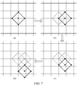
- the operation of moving the polygonal model, and obtaining an optimal point according to the moved polygonal model in a case that the first target point is inconsistent with the first undetermined point may include: moving a center of the polygonal model to a location of the first target point in a case that the first target point is inconsistent with the first undetermined point; and selecting a point with the minimum rate-distortion cost from the center of the moved polygonal model and each vertex, to obtain the optimal point.
- An original shape of the moved polygonal model remains unchanged.
- the center of the polygonal model may be moved to the location of the first target point. Then the rate-distortion cost of locations of the center of the moved polygonal model and each vertex is calculated, and the point with the minimum rate-distortion cost in the center of the moved polygonal model and each vertex is set as the optimal point.
- the video motion estimation apparatus may determine whether the optimal point is consistent with the first target point.
- a location of the optimal point is set as the current motion vector of the second type prediction unit in a case that the optimal point is consistent with the first target point.
- the video motion estimation method may further include: setting a location of the first target point as the current motion vector of the second type prediction unit in a case that the first target point is consistent with the first undetermined point.
- the center of the diamond model is moved to the location of the right vertex if the point (that is, the optimal point) with the minimum rate-distortion cost obtained through calculation of rate distortion cost of the center of the diamond model and upper, lower, left, and right vertexes in FIG. 7 (a) is a location of the right vertex of the diamond model, as shown in FIG. 7 (b) .
- the rate-distortion cost of the center of the moved diamond model and the upper, lower, left, and right vertexes is calculated.
- the center of the diamond model is moved to the location of the lower vertex, as shown in FIG. 7 (c) .
- the rate-distortion cost of the center of the moved diamond model and the upper, lower, left, and right vertexes is calculated.
- the obtained point with the minimum rate-distortion cost is a location of the lower vertex of the diamond model
- the center of the diamond model is moved to the location of the lower vertex, as shown in FIG. 7 (d) .
- the rate-distortion cost of the center of the moved diamond model and the upper, lower, left, and right vertexes is calculated.
- the obtained point with the minimum rate-distortion cost is a location of the center of the diamond model, that is, the optimal point is the location of the center of the diamond model, then the diamond model is no longer moved, and the location (that is, the location of the optimal point) of the center of the diamond model is set as a current motion vector of the second type prediction unit.
- the operation of obtaining a first undetermined point in the second type prediction unit according to the second search algorithm, obtaining a polygonal model centered on the first undetermined point, and obtaining a first target point according to the polygonal model in a case that a search step size of the first undetermined point is within a first preset step size threshold range may include:
- the video motion estimation apparatus may obtain a first candidate starting search point corresponding to the second type prediction unit through the AMVP technology, calculate rate-distortion cost of the first candidate starting search point, set the point with the minimum rate-distortion cost as a first starting search point, and then perform searching with the first starting search point as the center of a diamond template or a square template, to obtain a plurality of first candidate points. Rate-distortion cost of each first candidate point is calculated, and the point with the minimum rate-distortion cost is selected from the plurality of first candidate points and set as a first undetermined point.
- the video motion estimation apparatus may determine whether the search step size corresponding to the first undetermined point is within the first preset step size threshold range, where the first preset step size threshold range may be flexibly set according to actual needs.
- a polygonal model such as a quadrilateral model or a hexagonal model centered on the first undetermined point is obtained in a case that a search step size of the first undetermined point is within a first preset step size threshold range.
- the video motion estimation apparatus may calculate rate-distortion cost of locations of the center of the polygonal model and each vertex, and set the point with the minimum rate-distortion cost in the center of the polygonal model and each vertex as the first target point.
- the video motion estimation apparatus may further calculate rate-distortion cost of the center of the polygonal model, each vertex, and a location (or a location of a trisection point of each side) of a midpoint of each side, and set the point with the minimum rate-distortion cost as the first target point.
- the operation of obtaining a point with the minimum rate-distortion cost in the second type prediction unit according to the second search algorithm, to obtain the first undetermined point may include:
- the video motion estimation apparatus may obtain the first candidate starting search point corresponding to the second type prediction unit through the AMVP technology or the Merge mode, then calculate rate distortion cost of each first candidate starting search point, and set the first candidate starting search point with the minimum rate-distortion cost as a first starting search point, that is, the first starting search point is a finally determined starting search point corresponding to the second type prediction unit.
- the video motion estimation apparatus may search for, according to the first preset increasing step size, a plurality of first candidate points within the search window range centered on the first starting search point.
- the search window range may be a search range of the diamond template or the square template.
- the search window range may be an inner ring region corresponding to a maximum search step size of the diamond template or the square template.
- the corresponding search window range is the inner ring region of the diamond template corresponding to a search step size of 8.
- the first preset increasing step size may be a step size that increases by an integer power of 2, or may be flexibly set according to actual needs.
- the diamond template is used as an example.
- the first starting search point is used as the center of the diamond template. From a search step size of 1, searching is performed according to the step size increasing by an integer power of 2, to obtain a plurality of first candidate points.
- the first candidate point may be a vertex of the diamond template corresponding to each search step size, a midpoint between the two vertexes, and the like, for example, a location of a five-pointed star as marked in FIG. 4 .
- the rate-distortion cost of each first candidate point is calculated, the point with the minimum rate-distortion cost is selected from the plurality of first candidate points, and the point with the minimum rate-distortion cost in the plurality of first candidate points is set as the first undetermined point.
- the second type prediction unit includes a first dividing block and a second dividing block, and the operation of obtaining a first candidate starting search point corresponding to the second type prediction unit according to the second search algorithm, calculating rate-distortion cost of each first candidate starting search point, and setting the first candidate starting search point with the minimum rate-distortion cost as a first starting search point may include:
- the second type prediction unit may include a first dividing block with an index of 0 and a second dividing block with an index of 1.
- the video motion estimation apparatus may separately search for the motion vectors of the first dividing block and the second dividing block in the second type prediction unit.
- the motion vector of the searched first dividing block may be used for instructing the search process of the current second dividing block, that is, a location corresponding to the motion vector of the searched first dividing block may be used as one of starting search points of the current second dividing block.
- a location corresponding to the motion vector of the searched second dividing block is used as one of candidate starting search points of the current first dividing block, and a location corresponding to the motion vector of the searched first dividing block is to be used as one of the starting search points of the current second dividing block, for example.
- the video motion estimation apparatus may obtain at least one first candidate starting search point corresponding to the second dividing block in the second type prediction unit through the AMVP technology, and determine whether the first dividing block in the second type prediction unit has been searched, that is, determine whether the first dividing block in the second type prediction unit has been predicted.
- a prediction result of the first dividing block is obtained.
- the prediction result may be the motion vector of the first dividing block obtained through prediction.
- Rate-distortion cost of the location of the first dividing block may be calculated according to the prediction result of the first dividing block, that is, the rate-distortion cost of the location of the first dividing block may be calculated according to the motion vector of the first dividing block. For example, a corresponding location may be determined according to the motion vector of the first dividing block, the rate-distortion cost of the corresponding location is calculated, and the rate-distortion cost of the corresponding location obtained through calculation is set as the rate-distortion cost of the location of the first dividing block.
- the rate-distortion cost of each first candidate starting search point is calculated, the point with the minimum rate-distortion cost in at least one first candidate starting search point and the first dividing block is set as a starting search point of the second dividing block in the second type prediction unit, and the starting search point of the second dividing block is set as the second starting search point, so as to perform the operation of searching for, according to a first preset increasing step size, a plurality of first candidate points within the search window range centered on the first starting search point, and calculating rate-distortion cost of each first candidate point.
- the nR ⁇ 2N prediction unit is used as an example. Assuming that a dividing block with the index of 0 in the nR ⁇ 2N prediction unit has been predicted, in this case, when a dividing block with the index of 1 in the nR ⁇ 2N prediction unit is predicted, a location of the motion vector in the prediction result corresponding to the dividing block with the index of 0 may be used as one of locations of the candidate starting search point of the dividing block with the index of 1, so that the point with the minimum rate-distortion cost may be selected as the starting search point from the candidate starting search points. In this way, the starting search point is closer to an optimal location for motion estimation, and may exit the search process faster.
- the video motion estimation method may further include:
- the video motion estimation apparatus may determine whether the search step size corresponding to the first undetermined point is the first preset step size.
- the first preset step size may be flexibly set according to actual needs.
- the first preset step size may be set to 1, that is, when the search step size corresponding to the first undetermined point is 1, a second supplementary point not searched around each point corresponding to the first preset step size may be obtained, and the second supplementary point may include one or more points, as shown in FIG. 5 .
- vertexes corresponding to the diamond with the search step size of 1 are four points of 2, 4, 5, and 7 if the search step size corresponding to the obtained second undetermined point is 1.
- the obtained second undetermined point with the minimum rate-distortion cost is a location of 2
- two points of A and B are supplemented at the location of 2
- the two points of A and B may be set as second supplementary points.
- the obtained second undetermined point with the minimum rate-distortion cost is a location of 5
- two points of D and F are supplemented at the location of 5 and the two points of D and F may be set as second supplementary points. and so on.
- the video motion estimation apparatus may calculate rate-distortion cost of the first supplementary point, compare the rate-distortion cost of the first supplementary point with the rate-distortion cost of the first undetermined point, and determine whether the point with the minimum rate-distortion cost in the first supplementary point and the first undetermined point is the first undetermined point.
- a location of the first undetermined point is set as a current motion vector of the second type prediction unit in a case that the point with the minimum rate-distortion cost in the first undetermined point and the first supplementary point is the first undetermined point.
- a location of the point with the minimum rate-distortion cost in the first undetermined point and the first supplementary point is set as a current motion vector of the second type prediction unit in a case that the point with the minimum rate-distortion cost in the first undetermined point and the first supplementary point is not the first undetermined point.
- the video motion estimation method may further include: setting the first undetermined point as a first starting search point, and performing the operation of searching for, according to a first preset increasing step size, a plurality of first candidate points within a search window range centered on the first starting search point in a case that the search step size corresponding to the first undetermined point is within a second preset step size threshold range.
- the video motion estimation apparatus may determine whether the search step size corresponding to the first undetermined point is within the second preset step size threshold range, where the second preset step size threshold range may be flexibly set according to actual needs.
- the search step size corresponding to the first undetermined point is within the second preset step size threshold range
- the first undetermined point is set as a first starting search point, and the operation of searching for, according to the first preset increasing step size, a plurality of first candidate points within a search window range centered on the first starting search point, and calculating rate-distortion cost of each first candidate point is performed.
- the video motion estimation apparatus may obtain a motion vector of a searched prediction unit in an image frame, and correct the current motion vector according to the motion vector of the searched prediction unit, to obtain the motion vector of the second type prediction unit. Details may be described as follows.
- the video motion estimation apparatus may obtain a motion vector of a searched prediction unit in an image frame.
- the searched prediction unit may include one or more prediction units, may include one or more prediction units of the first type prediction unit in the image frame, or may include one or more prediction units of the second type prediction unit in the image frame, or may include both one or more prediction units of the first type prediction unit in the image frame and one or more prediction units of the second type prediction unit in the image frame. Then the current motion vector is corrected according to the motion vector of the searched prediction unit, to obtain the motion vector of the second type prediction unit.
- the operation of obtaining a motion vector of a searched prediction unit in an image frame, and correcting the current motion vector according to the motion vector of the searched prediction unit, to obtain the motion vector of the second type prediction unit may include:
- the video motion estimation apparatus may correct the current motion vector of the currently searched second type prediction unit according to the motion vector of the searched prediction unit in the image frame. Specifically, in the process of searching the motion vector of each prediction unit, the video motion estimation apparatus may store the motion vector of the searched prediction unit, and may generate a mapping relationship between a prediction unit identifier and the motion vector.
- the video motion estimation apparatus may obtain a mapping relationship corresponding to the searched prediction unit identifier, obtain the motion vector of the searched prediction unit in the image frame according to the mapping relationship, and calculate the first target rate-distortion cost of the corresponding location of the second type prediction unit according to the motion vector of the searched prediction unit. For example, a corresponding location may be determined according to the motion vector of the searched prediction unit, the rate-distortion cost of the corresponding location is calculated, and the rate-distortion cost of the corresponding location obtained through calculation is set as the first target rate-distortion cost.
- the video motion estimation apparatus may compare the current rate-distortion cost of the second type prediction unit with the first target rate-distortion cost. If the current rate-distortion cost of the second type prediction unit is greater than the first target rate-distortion cost, the motion vector of the searched prediction unit is set as the motion vector of the second type prediction unit. If the current rate-distortion cost of the second type prediction unit is less than or equal to the first target rate-distortion cost, a location of a point corresponding to the current rate-distortion cost is set as the motion vector of the second type prediction unit.
- the video motion estimation apparatus searches for a motion vector corresponding to each prediction unit in the order of a 2N ⁇ 2N prediction unit, a 2N ⁇ N prediction unit, an N ⁇ 2N prediction unit, a 2N ⁇ nU prediction unit, a 2N ⁇ nD prediction unit, an nL ⁇ 2N prediction unit, and an nR ⁇ 2N prediction unit
- motion vectors of the previously searched 2N ⁇ 2N prediction unit, 2N ⁇ N prediction unit, N ⁇ 2N prediction unit, 2N ⁇ nU prediction unit, and the like may be used for correcting the motion vector of the currently searched 2N ⁇ nD prediction unit when the 2N ⁇ nD prediction unit is currently searched.
- step S104 sub-pixel motion estimation is performed on the image frame according to the motion vector of the first type prediction unit and the motion vector of the second type prediction unit.
- the video motion estimation apparatus may perform sub-pixel motion estimation on the image frame according to the motion vector of the first type prediction unit and the motion vector of the second type prediction unit.
- the process of obtaining the motion vector of the first type prediction unit and the motion vector of the second type prediction unit is mainly obtaining an integer-pixel motion vector by performing integer-pixel motion prediction (that is, integer-pixel search) on the image frame.
- integer-pixel motion prediction that is, integer-pixel search
- the video motion estimation apparatus may perform a half-pixel search and a quarter-pixel precision search according to the motion vector obtained through integer-pixel motion prediction, to obtain a precision motion vector.
- Motion compensation processing is performed on the precision motion vector, for example, processing such as discrete cosine transform (DCT) quantization, and the like is performed on the obtained precision motion vector to obtain a residual coefficient. Then, the obtained residual coefficient is sent to an entropy encoding module to output a code stream. In addition, after the residual coefficient is inversely quantized and inversely transformed, a residual value of a reconstructed image is obtained, and the reconstructed image is obtained according to the residual value. The reconstructed image enters a reference frame queue after in-loop filtering, and is used as the reference image of the next frame, so that encoding is performed backward frame by frame.
- DCT discrete cosine transform
- image frames in a video may be divided into a plurality of prediction units, and the plurality of prediction units is classified.
- the plurality of prediction units is divided into a first type prediction unit and a second type prediction unit.
- motion vectors of different types of prediction units are obtained by using different search algorithms.
- a motion vector of the first type prediction unit is obtained according to a first search algorithm
- a motion vector of the second type prediction unit is obtained according to a second search algorithm.
- sub-pixel motion estimation may be performed on the image frame according to the motion vector of the first type prediction unit and the motion vector of the second type prediction unit.
- a plurality of prediction units may be classified, and the motion vectors of different types of prediction units are obtained by using different search algorithms, which leads to relatively high search efficiency. Therefore, in comparison to the same processing method used for different prediction units in the related art, efficiency and flexibility of performing motion estimation on the video are improved.
- the foregoing video motion estimation apparatus is to be described.
- the video motion estimation apparatus may be integrated in a terminal such as a computer, a mobile phone, a television, or the like that has a storage unit, is equipped with a microprocessor, and has computing capability as a computer. Description is to be given from the perspective of the terminal.
- the terminal may obtain the video from the local or a server, and divide the image frame in the video into a plurality of prediction units such as a 2N ⁇ 2N prediction unit, a 2N ⁇ N prediction unit, an N ⁇ 2N prediction unit, a 2N ⁇ nU prediction unit, a 2N ⁇ nD prediction unit, an nL ⁇ 2N prediction unit, an nR ⁇ 2N prediction unit, and the like by using an inter-frame prediction unit PU.
- a 2N ⁇ 2N prediction unit such as a 2N ⁇ 2N prediction unit, a 2N ⁇ N prediction unit, an N ⁇ 2N prediction unit, a 2N ⁇ nU prediction unit, a 2N ⁇ nD prediction unit, an nL ⁇ 2N prediction unit, an nR ⁇ 2N prediction unit, and the like by using an inter-frame prediction unit PU.
- the 2N ⁇ N prediction unit includes a dividing block with an index of 0 and a dividing block with an index of 1 divided at a ratio of 1:1 up and down
- the N ⁇ 2N prediction unit includes a dividing block with an index of 0 and a dividing block with an index of 1 divided at a ratio of 1:1 left and right
- the 2N ⁇ nU prediction unit includes a dividing block with an index of 0 and a dividing block with an index of 1 divided at a ratio of 1:3 up and down
- the 2N ⁇ nD prediction unit includes a dividing block with an index of 0 and a dividing block with an index of 1 divided at a ratio of 3:1 up and down
- the nL ⁇ 2N prediction unit includes a dividing block with an index of 0 and a dividing block with an index of 1 divided at a ratio of 1:3 left and right
- the nR ⁇ 2N prediction unit includes a dividing block with an index of 0 and a dividing block with
- the terminal may divide the obtained plurality of prediction units into a first type prediction unit and a second type prediction unit symmetrically.
- the first type prediction unit may include prediction units such as 2N ⁇ 2N, 2N ⁇ N, N ⁇ 2N, and the like in the symmetric mode
- the second type prediction unit may include prediction units such as 2N ⁇ nU, 2N ⁇ nD, nL ⁇ 2N, nR ⁇ 2N, and the like in the asymmetric mode.
- the terminal may respectively use different search algorithms to search for the motion vector of the prediction unit. Details are to be described below.
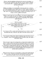
- FIG. 10 is a schematic flowchart of searching for a motion vector of a first type prediction unit according to an embodiment of this disclosure.
- the method process may include:
- a terminal obtains a second candidate starting search point corresponding to a first type prediction unit, and sets a second candidate starting search point with the minimum rate-distortion cost as a second starting search point.
- the terminal may obtain one or more second candidate starting search points through the AMVP technology or the Merge mode, calculate rate distortion cost of each second candidate starting search point, and set the second candidate starting search point with the minimum rate-distortion cost as a second starting search point, that is, the second starting search point is a finally determined starting search point corresponding to the first type prediction unit.
- the first type prediction unit may include a third dividing block with an index of 0 and a fourth dividing block with an index of 1.
- the terminal may separately search for motion vectors of the third dividing block and the fourth dividing block in the first type prediction unit.
- a location corresponding to the motion vector of the searched third dividing block may be used as one of candidate starting search points of the current fourth dividing block.
- the terminal may obtain at least one second candidate starting search point corresponding to the fourth dividing block in the first type prediction unit through the AMVP technology, and determine whether the third dividing block in the first type prediction unit has been predicted.
- a motion vector of the third dividing block obtained through prediction is obtained, a prediction point corresponding to the motion vector of the third dividing block obtained through prediction is determined, and rate-distortion cost of each second candidate starting search point and the third dividing block is calculated.
- the point with the minimum rate-distortion cost in the at least one second candidate starting search point and the third dividing block is set as the starting search point of the fourth dividing block in the first type prediction unit, and the starting search point of the fourth dividing block is set as the second starting search point, to perform step S202.
- a 2N ⁇ N prediction unit is used as an example. Assuming that a dividing block with the index of 0 in the 2N ⁇ N prediction unit has been predicted, in this case, when a dividing block with the index of 1 in the 2N ⁇ N prediction unit is predicted, a location corresponding to the motion vector in the prediction result corresponding to the dividing block with the index of 0 may be used as one of locations of the candidate starting search point of the dividing block with the index of 1, so that the point with the minimum rate-distortion cost may be selected as the starting search point from the candidate starting search points. In this way, the starting search point is closer to an optimal location for motion estimation, and may exit the search process faster.
- S202 The terminal obtains, according to a second preset increasing step size, a plurality of second candidate points within a search window range centered on the second starting search point, and selects a point with the minimum rate-distortion cost from the plurality of second candidate points, to obtain a second undetermined point.
- the terminal may perform searching, according to the second preset increasing step size by using a diamond template, a square template, or the like, within the search window range centered on the second starting search point, to obtain the plurality of second candidate points.
- the square template is used as an example, and the second starting search point is used as a center of the square template.
- a search step size of 1 a plurality of second candidate points are obtained, according to the second preset increasing step size, within the search window range centered on the second starting search point.
- the second preset increasing step size may increase by an integer power of 2, that is, from the search step size of 1, searching is performed with the search step sizes of 2, 4, and 8 in turn, to obtain a plurality of second candidate points.
- the second candidate points may be vertexes of the square template corresponding to each search step size, a point corresponding to a quarter between two vertexes, and the like.
- a corresponding search window range is an inner ring region of the square template corresponding to the search step size 8.
- a corresponding search window range is an inner ring region of the square template corresponding to the search step size 16, and so on.
- the rate-distortion cost of each second candidate point is calculated, the point with the minimum rate-distortion cost is selected from the plurality of second candidate points, and the point with the minimum rate-distortion cost in the plurality of second candidate points is set as the second undetermined point.
- S203 The terminal obtains a second supplementary point not searched around each point corresponding to the second preset step size in a case that the search step size corresponding to the second undetermined point is a second preset step size.
- the terminal may determine whether the search step size corresponding to the second undetermined point is a second preset step size.
- the second preset step size may be flexibly set according to actual needs, for example, the second preset step size may be set to 1, 2, or the like.
- the terminal obtains a second supplementary point not searched around each point corresponding to the second preset step size in a case that the search step size corresponding to the second undetermined point is a second preset step size.
- the search template for searching for the second undetermined point is a square template and the search step size corresponding to the obtained second undetermined point is 1
- vertexes corresponding to the square with the search step size of 1 are four points of 1, 3, 6, and 8, and 2, 4, 5, and 7 are midpoints of each side of the square.
- the obtained second undetermined point with the minimum rate-distortion cost is a location of 1
- two points of A and C are supplemented at the location of 1, and the two points of A and C may be set as second supplementary points.
- the obtained second undetermined point with the minimum rate-distortion cost is a location of 2
- two points of A and B are supplemented at the location of 2
- the two points of A and B may be set as second supplementary points.
- the obtained second undetermined point with the minimum rate-distortion cost is a location of 3
- two points of B and D are supplemented at the location of 3
- the two points of B and D may be set as second supplementary points.
- the obtained second undetermined point with the minimum rate-distortion cost is a location of 4
- two points of C and E are supplemented at the location of 4
- the two points of C and E may be set as second supplementary points.
- the obtained second undetermined point with the minimum rate-distortion cost is a location of 5, then two points of D and F are supplemented at the location of 5, and the two points of D and F may be set as second supplementary points. If the obtained second undetermined point with the minimum rate-distortion cost is a location of 6, then two points of E and G are supplemented at the location of 6, and the two points of E and G may be set as second supplementary points. If the obtained second undetermined point with the minimum rate-distortion cost is a location of 7, then two points of G and H are supplemented at the location of 7, and the two points of G and H may be set as second supplementary points. If the obtained second undetermined point with the minimum rate-distortion cost is a location of 8, then two points of F and H are supplemented at the location of 8, and the two points of F and H may be set as second supplementary points.
- step S204 The terminal determines whether a point with minimum rate-distortion cost in the second undetermined point and the second supplementary point is the second undetermined point; if yes, performs step S205; and if not, performs step S206.
- the terminal may calculate rate-distortion cost of each second supplementary point, compare the rate-distortion cost of the second supplementary point with the rate-distortion cost of the second undetermined point, and determine whether the point with the minimum rate-distortion cost in the second supplementary point and the second undetermined point is the second undetermined point.
- S205 The terminal sets a location of the second undetermined point as a motion vector of the first type prediction unit, and corrects the motion vector.
- a location of the point with the minimum rate-distortion cost in the second undetermined point and the second supplementary point is set as a motion vector of a first type image block, and the motion vector is corrected.
- the terminal sets the location of the second undetermined point as a motion vector of the first type prediction unit in a case that the point with the minimum rate-distortion cost in the second undetermined point and the second supplementary point is the second undetermined point.
- the terminal sets the location of a point with the minimum rate-distortion cost in the second undetermined point and the second supplementary point as the motion vector of the first type image block in a case that the point with the minimum rate-distortion cost in the second undetermined point and the second supplementary point is not the second undetermined point.
- the terminal may correct the motion vector of the first type prediction unit. Specifically, in the process of searching for the motion vector of each prediction unit, the terminal may store the motion vector of the searched prediction unit, and may generate a mapping relationship between a prediction unit identifier and the motion vector.
- the terminal may obtain a mapping relationship corresponding to the searched prediction unit identifier, obtain the motion vector of the searched prediction unit in the image frame according to the mapping relationship, and calculate second target rate-distortion cost of the first type prediction unit according to the motion vector of the searched prediction unit. Then, the rate-distortion cost of the second undetermined point may be compared with the second target rate-distortion cost.
- the location of the second undetermined point is set as the motion vector of the first type prediction unit in a case that the rate-distortion cost of the second undetermined point is less than or equal to the second target rate-distortion cost.
- the motion vector of each prediction unit may be named in advance, and a naming algorithm may be: mv_best_prediction unit type_prediction unit index, for example, mv_best_2N ⁇ N_PU1 indicates a motion vector of a dividing block with an index of 1 in the 2N ⁇ N prediction unit.
- mv_best_prediction unit type_prediction unit index indicates a motion vector of a dividing block with an index of 1 in the 2N ⁇ N prediction unit.
- the terminal performs searching, according to a preset interval step size, within a preset range centered on the second undetermined point in a case that the search step size corresponding to the second undetermined point is within a third preset step size threshold range, to obtain a plurality of search points, uses the point with the minimum rate-distortion cost in the second undetermined point and the plurality of search points as a second starting search point, and performs step S202.
- the terminal may determine whether the search step size corresponding to the second undetermined point is within a third preset step size threshold range, where the third preset step size threshold range may be flexibly set according to actual needs, and a specific value is not limited herein.
- Searching is performed according to a preset interval step size within a preset range centered on the second undetermined point in a case that the search step size corresponding to the second undetermined point is within a third preset step size threshold range, to obtain a plurality of search points.
- the preset range and the preset interval step size may be flexibly set according to actual needs, and a specific value is not limited herein. For example, as shown in FIG. 6 , within the search window range centered on the second undetermined point, all points are scanned every 5 rows and 5 columns by raster scanning, to obtain a plurality of search points.
- rate-distortion cost of each search point is calculated, the point with the minimum rate-distortion cost in the second undetermined point and the plurality of search points is used as the second starting search point, and the operation of obtaining, according to the second preset increasing step size, a plurality of second candidate points within the search window range centered on the second starting search point, and selecting the point with the minimum rate-distortion cost from the plurality of second candidate points, to obtain a second undetermined point is performed.
- the terminal may determine whether the search step size corresponding to the second undetermined point is within the fourth step size threshold range, where the fourth preset step size threshold range may be flexibly set according to actual needs, and the specific content is not limited herein.
- the second undetermined point is used as the second starting search point, and the operation of obtaining, according to the second preset increasing step size, a plurality of second candidate points within the search window range centered on the second starting search point, and selecting the point with the minimum rate-distortion cost from the plurality of second candidate points, to obtain a second undetermined point is performed.
- FIG. 11 is a schematic flowchart of searching for a motion vector of a second type prediction unit according to an embodiment of this disclosure.
- the method process may include:
- a terminal obtains a first candidate starting search point corresponding to a second type prediction unit, and sets a first candidate starting search point with the minimum rate-distortion cost as a first starting search point.
- the terminal may obtain the first candidate starting search point corresponding to the second type prediction unit through the AMVP technology or the Merge mode, then calculate rate distortion cost of each first candidate starting search point, and set the first candidate starting search point with the minimum rate-distortion cost as a first starting search point, that is, the first starting search point is a finally determined starting search point corresponding to the second type prediction unit.
- the second type prediction unit may include a first dividing block with an index of 0 and a second dividing block with an index of 1.
- the terminal may separately search for motion vectors of the first dividing block and the second dividing block in the second type prediction unit.
- a location corresponding to the motion vector of the searched first dividing block may be used as one of starting search points of the current second dividing block.
- the terminal may obtain at least one first candidate starting search point corresponding to the second dividing block in the second type prediction unit through the AMVP technology, and determine whether the first dividing block in the second type prediction unit has been searched, that is, determine whether the first dividing block in the second type prediction unit has been predicted.
- a motion vector of the first dividing block obtained through prediction is obtained, a prediction point corresponding to the motion vector of the first dividing block obtained through prediction is determined, and rate-distortion cost of each first candidate starting search point and the first dividing block is calculated.
- the point with the minimum rate-distortion cost in the at least one first candidate starting search point and the first dividing block is set as the starting search point of the second dividing block in the second type prediction unit, and the starting search point of the second dividing block is set as the second starting search point, to perform step S302.
- a 2N ⁇ nD prediction unit is used as an example. If a dividing block with the index of 0 in the 2N ⁇ nD prediction unit has been predicted, in this case, when a dividing block with the index of 1 in the 2N ⁇ nD prediction unit is predicted, a location of the motion vector corresponding to the dividing block with the index of 0 may be used as one of locations of the candidate starting search point of the dividing block with the index of 1, so that the point with the minimum rate-distortion cost may be selected as the starting search point from the candidate starting search points. In this way, the starting search point is closer to an optimal location for motion estimation, and may exit the search process faster.
- S302 The terminal obtains, according to a first preset increasing step size, a plurality of first candidate points within a search window range centered on the first starting search point, and selects a point with the minimum rate-distortion cost from the plurality of first candidate points, to obtain a first undetermined point.
- the terminal may search for, according to the first preset increasing step size, a plurality of first candidate points within the search window range centered on the first starting search point.
- the search window range may be a search range of a diamond template or a square template.
- the search window range may be an inner ring region corresponding to a maximum search step size of the diamond template or the square template.
- the corresponding search window range is the inner ring region of the diamond template corresponding to a search step size of 8.
- the first preset increasing step size may be a step size that increases by an integer power of 2, or may be flexibly set according to actual needs.
- the square template is used as an example, and the first starting search point is used as a center of the square template.
- a search step size of 1 a plurality of first candidate points are searched, according to a search step size increasing by an integer power of 2, within the search window range centered on the first starting search point, to obtain a plurality of first candidate points.
- the first candidate points may be vertexes of the square template corresponding to each search step size, a point corresponding to a quarter between two vertexes, and the like.
- the rate-distortion cost of each first candidate point is calculated, the point with the minimum rate-distortion cost is selected from the plurality of first candidate points, and the point with the minimum rate-distortion cost in the plurality of first candidate points is set as the first undetermined point.
- the terminal may determine whether the search step size corresponding to the first undetermined point is within a first preset step size threshold range, where the first preset step size threshold range may be flexibly set according to actual needs, and a specific value is not limited herein.
- the terminal When a search step size of the first undetermined point is within the first preset step size threshold range, the terminal obtains a polygonal model centered on the first undetermined point, and the polygonal model may be quadrilateral, hexagonal, or the like.
- the terminal may calculate rate-distortion cost of locations of the center of the polygonal model and each vertex, and set a point with the minimum rate-distortion cost in the center of the polygonal model and each vertex as the first target point.
- the terminal may determine whether the first target point is consistent with the first undetermined point. When the first target point is consistent with the first undetermined point, the terminal may set the location of the first target point as the current motion vector of the second type prediction unit.
- the terminal may obtain a motion vector of a searched prediction unit in an image frame.
- the searched prediction unit may include one or more prediction units, and correct the current motion vector of the second prediction unit according to the motion vector of the searched prediction unit, to obtain the motion vector of the second type prediction unit.
- the terminal may store the motion vector of the searched prediction unit, and may generate a mapping relationship between a prediction unit identifier and the motion vector.
- the terminal may obtain a mapping relationship corresponding to the searched prediction unit identifier, obtain the motion vector of the searched prediction unit in the image frame according to the mapping relationship, and calculate first target rate-distortion cost of the second type prediction unit according to the motion vector of the searched prediction unit.
- the terminal may compare the current rate-distortion cost of the second type prediction unit with the first target rate-distortion cost. If the current rate-distortion cost of the second type prediction unit is greater than the first target rate-distortion cost, the motion vector of the searched prediction unit is set as the motion vector of the second type prediction unit. If the current rate-distortion cost of the second type prediction unit is less than or equal to the first target rate-distortion cost, a location of a point corresponding to the current rate-distortion cost is set as the motion vector of the second type prediction unit.
- the motion vector of each prediction unit may be named in advance, and a naming algorithm may be: mv_best_prediction unit type_prediction unit index, for example, mv_best_2N ⁇ N_PU1 indicates a motion vector of a dividing block with an index of 1 in a 2N ⁇ N prediction unit.
- the motion vector of the searched prediction unit in the image frame may include: ⁇ mv_best_2N ⁇ 2N_PU0, mv_best_2N ⁇ 2N_PU1 ⁇ .
- the motion vector of the searched prediction unit in the image frame may include: ⁇ mv_best_2N ⁇ 2N_PU0, mv_best_2N ⁇ 2N_PU1, mv_best_2N ⁇ N_PU0, mv_best_2N ⁇ N_PU1 ⁇ .
- the motion vector of the searched prediction unit in the image frame may include: ⁇ mv_best_2N ⁇ 2N_PU0, mv_best_2N ⁇ 2N_PU1, mv_best_2N ⁇ N_PU0, mv_best_2N ⁇ N_PU1, mv_best_N ⁇ 2N_PU0, mv_best_N ⁇ 2N_PU1 ⁇ .
- the motion vector of the searched prediction unit in the image frame may include: ⁇ mv_best_2N ⁇ 2N_PU0, mv_best_2N ⁇ 2N_PU1, mv_best_2N ⁇ N_PU0, mv_best_2N ⁇ N_PU1, mv_best_N ⁇ 2N_PU0, mv_best_N ⁇ 2N_PU1, mv_best_2N ⁇ nU_PU0, mv_best_2N ⁇ nU_PU1 ⁇ .
- the motion vector of the searched prediction unit in the image frame may include: ⁇ mv_best_2N ⁇ 2N_PU0, mv_best_2N ⁇ 2N_PU1, mv_best_2N ⁇ N_PU0, mv_best_2N ⁇ N_PU1, mv_best_N ⁇ 2N_PU0, mv_best_N ⁇ 2N_PU1, mv_best_2N ⁇ nU_PU0, mv_best_2N ⁇ nU_PU1, mv_best_2N ⁇ nD_PU0, mv_best_2N ⁇ nD_PU1 ⁇ .
- the motion vector of the searched prediction unit in the image frame may include: ⁇ mv_best_2N ⁇ 2N_PU0, mv_best_2N ⁇ 2N_PU1, mv_best_2N ⁇ N_PU0, mv_best_2N ⁇ N_PU1, mv_best_N ⁇ 2N_PU0, mv_best_N ⁇ 2N_PU1, mv_best_2N ⁇ nU_PU0, mv_best_2N ⁇ nU_PU1, mv_best_2N ⁇ nD_PU0, mv_best_2N ⁇ nD_PU1, mv_best_nL ⁇ 2N_PU0, mv_best_nL ⁇ 2N_PU1 ⁇ .
- the terminal moves a center of the polygonal model to a location of the first target point, and selects a point with the minimum rate-distortion cost from the center of the moved polygonal model and each vertex, to obtain an optimal point.
- the terminal may move a center of the polygonal model to a location of the first target point, and an original shape remains unchanged after the polygonal model is moved. Then the rate-distortion cost of locations of the center of the moved polygonal model and each vertex is calculated, and the point with the minimum rate-distortion cost in the center of the moved polygonal model and each vertex is set as the optimal point.
- the polygonal model is a hexagonal model and the point (that is, the optimal point) with the minimum rate-distortion cost obtained by calculating rate-distortion cost of a center of the hexagonal model and each vertex in FIG. 8 (a) is a location of a right vertex of the hexagonal model
- the center of the hexagonal model is moved to the location of the right vertex, as shown in FIG. 8 (b) .
- the rate-distortion cost of a center of the moved hexagonal model and each vertex is calculated.
- the center of the hexagonal model is moved to the location of the top right vertex, as shown in FIG. 8(c) . In this case, the rate-distortion cost of the center and each vertex of the moved hexagonal model is calculated. If the obtained point with the minimum rate-distortion cost is a location of a top left vertex of the hexagonal model, the center of the hexagonal model is moved to the location of the top left vertex, as shown in FIG. 8(d) . In this case, the rate-distortion cost of the center and each vertex of the moved hexagonal model is calculated.
- the obtained point with the minimum rate-distortion cost is a location of the center of the hexagonal model, that is, the optimal point is the location of the center of the hexagonal model, then the hexagonal model is no longer moved, and the location (that is, the location of the optimal point) of the center of the hexagonal model is set as the current motion vector of the second type prediction unit.
- step S306 The terminal determines whether the optimal point is consistent with the first target point; if yes, performs step S307; and if not, performs step S308.
- the terminal may determine whether the optimal point is consistent with the first target point.
- S307 The terminal sets a location of the optimal point as a current motion vector of the second type prediction unit, and corrects the current motion vector, to obtain a motion vector of the second type prediction unit.
- the terminal may set a location of the optimal point as the current motion vector of the second type prediction unit.
- the terminal may correct the obtained current motion vector of the second type prediction unit according to the method of correcting the current motion vector of the second type prediction unit.
- S308 The terminal sets the optimal point as the first starting search point, and performs step S302.
- the terminal sets the optimal point as the first starting search point, and performs the operation of searching, according to a first preset increasing step size, a plurality of first candidate points within a search window range centered on the first starting search point, and selecting the point with the minimum rate-distortion cost from the plurality of first candidate points, to obtain the first undetermined point.
- the terminal obtains a first supplementary point not searched around each point corresponding to the first preset step size in a case that the search step size corresponding to the first undetermined point is a first preset step size.
- the terminal may determine whether the search step size corresponding to the first undetermined point is the first preset step size, where the first preset step size threshold range may be flexibly set according to actual needs, and a specific value is not limited herein.
- the terminal may obtain a first supplementary point not searched around each point corresponding to the first preset step size in a case that the search step size corresponding to the first undetermined point is the first preset step size.
- the search template for searching for the first undetermined point is a square template and the search step size corresponding to the obtained first undetermined point is 1, vertexes corresponding to the square with the search step size of 1 are four points of 1, 3, 6, and 8, and 2, 4, 5, and 7 are midpoints of each side of the square.
- the obtained first undetermined point with the minimum rate-distortion cost is a location of 1
- two points of A and C are supplemented at the location of 1, and the two points of A and C may be set as first supplementary points.
- the obtained first undetermined point with the minimum rate-distortion cost is a location of 3
- two points of B and D are supplemented at the location of 3
- the two points of B and D may be set as first supplementary points.
- the obtained first undetermined point with the minimum rate-distortion cost is a location of 6
- two points of E and G are supplemented at the location of 6
- the two points of E and G may be set as first supplementary points.
- the obtained first undetermined point with the minimum rate-distortion cost is a location of 8
- two points of F and H are supplemented at the location of 8
- the two points of F and H may be set as first supplementary points.
- step S310 The terminal determines whether the point with the minimum rate-distortion cost in the first undetermined point and the first supplementary point is the first undetermined point; if yes, performs step S311; and if not, performs step S312.
- the terminal may calculate rate-distortion cost of the first supplementary point, compare the rate-distortion cost of the first supplementary point with the rate-distortion cost of the first undetermined point, and determine whether the point with the minimum rate-distortion cost in the first supplementary point and the first undetermined point is the first undetermined point.
- S311 The terminal sets a location of the first undetermined point as a current motion vector of the second type prediction unit, and corrects the current motion vector, to obtain a motion vector of the second type prediction unit.
- a location of the first undetermined point is set as a current motion vector of the second type prediction unit in a case that the point with the minimum rate-distortion cost in the first undetermined point and the first supplementary point is the first undetermined point.
- the terminal may correct the obtained current motion vector of the second type prediction unit according to the method of correcting the current motion vector of the second type prediction unit, to obtain a motion vector of a second type image block.
- S312 The terminal sets a location of a point with the minimum rate-distortion cost in the first undetermined point and the first supplementary point as a current motion vector of the second type image block, and corrects the current motion vector, to obtain the motion vector of the second type image block.
- the terminal may set the location of a point with the minimum rate-distortion cost in the first undetermined point and the first supplementary point as the current motion vector of the second type image block in a case that the point with the minimum rate-distortion cost in the first undetermined point and the first supplementary point is not the first undetermined point.
- the terminal may correct the obtained current motion vector of the second type prediction unit according to the method of correcting the current motion vector of the second type prediction unit, to obtain the motion vector of the second type image block.
- the terminal may determine whether the search step size corresponding to the first undetermined point is within a second preset step size threshold range, where the second preset step size threshold range may be flexibly set according to actual needs, and a specific value is not limited herein.
- the first undetermined point is set as the first starting search point, and the operation of searching for, according to the first preset increasing step size, a plurality of first candidate points within a search window range centered on the first starting search point, and selecting a point with the minimum rate-distortion cost from the plurality of first candidate points, to obtain the first undetermined point is performed.
- the terminal may perform sub-pixel motion estimation on the image frame according to the motion vector of the first type prediction unit and the motion vector of the second type prediction unit. For example, the terminal may perform processing such as discrete cosine transform and quantization according to the obtained motion vector, to obtain a residual coefficient. Then, the obtained residual coefficient is sent to an entropy encoding module to output a code stream. In addition, after the residual coefficient is inversely quantized and inversely transformed, a residual value of a reconstructed image is obtained, and the reconstructed image is obtained according to the residual value.
- the reconstructed image enters a reference frame queue after in-loop filtering, and is used as the reference image of the next frame, so that encoding is performed backward frame by frame.
- the image frame in a video may be divided into a plurality of prediction units, and the plurality of prediction units are divided into a first type prediction unit and a second type prediction unit.
- a more complex search algorithm may be used for searching
- a fast search algorithm may be used for searching, thereby accelerating the process of motion estimation.
- reference may be made to the final search result of the searched dividing block, thereby accelerating the process of motion estimation.
- some results that a partial optimal location may be searched are corrected by using a correction strategy to avoid a search error, so that an encoding speed is greatly increased, and a compression ratio loss is less.
- an embodiment of this disclosure further provides an apparatus based on the foregoing video motion estimation method.
- the meaning of the noun is the same as that in the foregoing video motion estimation method.
- FIG. 12 is a schematic structural diagram of a video motion estimation apparatus according to an embodiment of this disclosure.
- the video motion estimation apparatus may include a dividing unit 401, a first obtaining unit 402, a second obtaining unit 403, and a motion estimation unit 404.
- the dividing unit 401 is configured to divide image frames in a video into a plurality of prediction units, and divide the plurality of prediction units into a first type prediction unit and a second type prediction unit.
- step S101 For specific implementation of the dividing unit 401, reference may be made to the embodiment described for step S101.
- the first obtaining unit 402 is configured to obtain a motion vector of the first type prediction unit according to a first search algorithm.
- step S102 For specific implementation of the first obtaining unit 402, reference may be made to the embodiment described for step S102.
- the first obtaining unit 402 may include a second obtaining subunit 4021, a calculation subunit 4022, a third obtaining subunit 4023, a third setting subunit 4024, a fourth setting subunit 4025, and the like, which may be specifically described below.
- the second obtaining subunit 4021 is configured to obtain a second candidate starting search point corresponding to the first type prediction unit, calculate rate-distortion cost of each second candidate starting search point, and set a second candidate starting search point with the minimum rate-distortion cost as a second starting search point.
- the calculation subunit 4022 is configured to obtain, according to the second preset increasing step size, a plurality of second candidate points within the search window range centered on the second starting search point, calculate rate-distortion cost of each second candidate point, and select a point with the minimum rate-distortion cost from the plurality of second candidate points, to obtain a second undetermined point.
- the third obtaining subunit 4023 is configured to obtain a second supplementary point not searched around each point corresponding to the second preset step size, and calculate rate-distortion cost of the second supplementary point in a case that the search step size corresponding to the second undetermined point is a second preset step size.
- the third setting subunit 4024 is configured to set a location of the second undetermined point as the motion vector of the first type prediction unit in a case that the point with the minimum rate-distortion cost in the second undetermined point and the second supplementary point is the second undetermined point.
- the fourth setting subunit 4025 is configured to set the second undetermined point as the second starting search point when the point with the minimum rate-distortion cost in the second undetermined point and the second supplementary point is not the second undetermined point, and the calculation subunit performs the operation of obtaining, according to the second preset increasing step size, a plurality of second candidate points within the search window range centered on the second starting search point, calculating the rate-distortion cost of each second candidate point, and selecting the point with the minimum rate-distortion cost from the plurality of second candidate points, to obtain the second undetermined point.
- the second obtaining subunit 4021 For specific implementation of the second obtaining subunit 4021, the calculation subunit 4022, the third obtaining subunit 4023, the third setting subunit 4024, and the fourth setting subunit 4025, reference may be made to the embodiment described for the operation of obtaining the motion vector of the first type prediction unit according to the first search algorithm.
- the third setting subunit 4024 is specifically configured to:
- the third setting subunit 4024 For specific implementation of the third setting subunit 4024, reference may be made to the embodiment described for the operation of setting the location of the second undetermined point as the motion vector of the first type prediction unit.
- the second type prediction unit includes a third dividing block and a fourth dividing block.
- the second obtaining subunit 4021 is specifically configured to:
- the second obtaining subunit 4021 For specific implementation of the second obtaining subunit 4021, reference may be made to the embodiment described for the operation of obtaining a second candidate starting search point corresponding to the first type prediction unit, calculating rate-distortion cost of each second candidate starting search point, and setting a second candidate starting search point with the minimum rate-distortion cost as a second starting search point.
- the first obtaining unit 402 may further include:
- the first obtaining unit 402 may further include: a second execution subunit configured to use the second undetermined point as the second starting search point, a calculation subunit performing the operation of obtaining, according to the second preset increasing step size, a plurality of second candidate points within the search window range centered on the second starting search point, calculating the rate-distortion cost of each second candidate point, and selecting the point with the minimum rate-distortion cost from the plurality of second candidate points, to obtain a second undetermined point in a case that a search step size corresponding to the second undetermined point is within a fourth preset step size threshold range.
- the second obtaining unit 403 is configured to obtain a motion vector of the second type prediction unit according to a second search algorithm.
- the second obtaining unit 403 may include a first obtaining subunit 4031 and a correction subunit 4032, and the like, which may be specifically described below.
- the first obtaining subunit 4031 is configured to obtain a polygonal model according to the second search algorithm, and obtain a current motion vector of the second type prediction unit by moving the polygonal model.
- the correction subunit 4032 is configured to obtain a motion vector of a searched prediction unit in an image frame, and correct the current motion vector according to the motion vector of the searched prediction unit, to obtain the motion vector of the second type prediction unit.
- step S103 For specific implementation of the second obtaining unit 403, reference may be made to the embodiment described for step S103.
- the first obtaining subunit 4031 may include:
- search module For specific implementation of the search module, the obtaining module, and the mobile module, reference may be made to the embodiment described for the operation of obtaining a polygonal model according to the second search algorithm, and obtaining a current motion vector of the second type prediction unit by moving the polygonal model.
- the mobile module may be specifically configured to:
- the first obtaining subunit 4031 may further include: a second setting module configured to set a location of the first target point as the current motion vector of the second type prediction unit in a case that the first target point is consistent with the first undetermined point.
- a second setting module configured to set a location of the first target point as the current motion vector of the second type prediction unit in a case that the first target point is consistent with the first undetermined point.
- the search module may include: a search submodule configured to obtain a point with the minimum rate-distortion cost in the second type prediction unit according to the second search algorithm, to obtain the first undetermined point.
- the obtaining module is specifically configured to:
- search module and the obtaining module For specific implementation of the search module and the obtaining module, reference may be made to the embodiment described for the operation of obtaining a first undetermined point in the second type prediction unit according to the second search algorithm, obtaining a polygonal model centered on the first undetermined point, and obtaining a first target point according to the polygonal model in a case that a search step size of the first undetermined point is within a first preset step size threshold range.
- search submodule may be specifically configured to:
- search submodule For specific implementation of the search submodule, reference may be made to the embodiment described for the operation of obtaining a point with the minimum rate-distortion cost in the second type prediction unit according to the second search algorithm, to obtain the first undetermined point.
- the second type prediction unit includes a first dividing block and a second dividing block.
- the search submodule is specifically configured to:
- first dividing block For specific implementation of the first dividing block, the second dividing block, and the search submodule, reference may be made to the embodiment described for the operation of obtaining a first candidate starting search point corresponding to the second type prediction unit according to the second search algorithm, calculating rate-distortion cost of each first candidate starting search point, and setting a first candidate starting search point with the minimum rate-distortion cost as a first starting search point.
- the obtaining module may be specifically configured to:
- the obtaining module For specific implementation of the obtaining module, reference may be made to the embodiment described after the operation of obtaining a point with the minimum rate-distortion cost in the second type prediction unit according to the second search algorithm, to obtain the first undetermined point.
- the obtaining module may be specifically configured to: set the first undetermined point as a first starting search point, and perform the operation of obtaining, according to a first preset increasing step size, a plurality of first candidate points within a search window range centered on the first starting search point in a case that the search step size corresponding to the first undetermined point is within a second preset step size threshold range.
- correction subunit 4032 is specifically configured to:
- correction subunit 4032 For specific implementation of the correction subunit 4032, reference may be made to the embodiment described for the operation of obtaining a motion vector of a searched prediction unit in an image frame, and correcting the current motion vector according to the motion vector of the searched prediction unit, to obtain the motion vector of the second type prediction unit.
- the motion estimation unit 404 is configured to perform sub-pixel motion estimation on the image frame according to the motion vector of the first type prediction unit and the motion vector of the second type prediction unit.
- step S104 For specific implementation of the motion estimation unit 404, reference may be made to the embodiment described for step S104.
- an embodiment of this disclosure further provides a terminal.
- the terminal may include components such as a radio frequency (RF) circuit 601, a memory 602 including one or more computer readable storage media, an input unit 603, a display unit 604, a sensor 605, an audio circuit 606, a wireless fidelity (WiFi) module 607, a processor 608 including one or more processing cores, a power supply 609, and the like.
- RF radio frequency
- the terminal structure shown in FIG. 15 does not constitute a limitation on the terminal, and may include more or fewer components than shown, or combine some components, or have different component arrangements.
- the RF circuit 601 may be configured to receive and send a signal during the sending and receiving of information or during a call.
- downlink information of a base station is processed by one or more processors 608 after being received.
- uplink data is sent to the base station.
- the RF circuit 601 includes but is not limited to an antenna, at least one amplifier, a tuner, one or more oscillators, a subscriber identity module (SIM) card, a transceiver, a coupler, a low noise amplifier (LNA), duplexer, and the like.
- SIM subscriber identity module
- LNA low noise amplifier
- the RF circuit 601 may further communicate with other devices via wireless communication and a network.
- the wireless communication may use any communication standard or protocol, including but not limited to the Global System of Mobile Communication (GSM), general packet radio service (GPRS), and Code Division Multiple Access (CDMA), Wideband Code Division Multiple Access (WCDMA), Long Term Evolution (LTE), email, short messaging service (SMS), and the like.
- GSM Global System of Mobile Communication
- GPRS general packet radio service
- CDMA Code Division Multiple Access
- WCDMA Wideband Code Division Multiple Access
- LTE Long Term Evolution
- email short messaging service
- SMS short messaging service
- the memory 602 may be configured to store a computer readable instruction and a module, and the processor 608 executes various function applications and performs data processing by running the computer readable instruction and the module that are stored in the memory 602.
- the memory 602 may mainly include a computer readable instruction storage area and a data storage area, where the computer readable instruction storage area may store an operating system, an application required for at least one function (such as a sound playback function, an image playback function, and the like), and the like.
- the data storage area may store data (such as audio data, a phone book, and the like) created according to the use of the terminal, and the like.
- the memory 602 may include a high speed random access memory, and may further include a non-volatile memory, such as at least one magnetic disk storage device, a flash memory device or other non-volatile solid state storage devices. Accordingly, the memory 602 may further include a memory controller to provide access to the memory 602 by the processor 608 and the input unit 603.
- a non-volatile memory such as at least one magnetic disk storage device, a flash memory device or other non-volatile solid state storage devices.
- the memory 602 may further include a memory controller to provide access to the memory 602 by the processor 608 and the input unit 603.
- the input unit 603 may be configured to receive information about an input number or character, and generate input of a keyboard, a mouse, a joystick, an optical or trackball signal that are related to user settings and function control.
- the input unit 603 may include a touch-sensitive surface and other input devices.
- the touch-sensitive surface is also referred to as a touch screen or a touchpad, which may collect a touch operation (for example, an operation on the touch-sensitive surface or near the touch-sensitive surface by a user by using any suitable object or accessory such as a finger, a stylus, and the like) on the touch-sensitive surface or near the touch-sensitive surface, and drive a corresponding connection apparatus according to a preset program.
- the touch-sensitive surface may include a touch detection apparatus and a touch controller.
- the touch detection apparatus detects a touch orientation of the user, detects a signal brought by the touch operation, and transmits the signal to the touch controller.
- the touch controller receives touch information from the touch detection apparatus, converts the touch information into a contact coordinate, then sends the contact coordinate to the processor 608, receives and executes a command sent by the processor 608.
- a variety of types such as resistive, capacitive, infrared, and surface acoustic waves may be used for implementing the touch-sensitive surface.
- the input unit 603 may further include other input devices. Specifically, other input devices may include but are not limited to one or more of a physical keyboard, a function key (such as a volume control key, a switch key, and the like), a trackball, a mouse, a joystick, and the like.
- the display unit 604 may be configured to display information input by the user or provided to the user, and various graphical user interfaces of the terminal. These graphical user interfaces may be composed of graphics, text, icons, videos, and any combination thereof.
- the display unit 604 may include a display panel.
- the display panel may be configured in the form of a liquid crystal display (LCD), an organic light-emitting diode (OLED), or the like.
- the touch-sensitive surface may cover the display panel. After the touch-sensitive surface detects a touch operation on the touch-sensitive surface or near the touch-sensitive surface, the touch operation is transmitted to the processor 608 to determine a type of a touch event, and then the processor 608 provides corresponding visual output on the display panel according to the type of the touch event.
- the touch-sensitive surface and the display panel are used as two independent components to implement the input and input functions, but in some embodiments, the touch-sensitive surface and the display panel may be integrated to implement the input and output functions.
- the terminal may further include at least one sensor 605, such as an optical sensor, a motion sensor, and other sensors.
- the optical sensor may include an ambient light sensor and a proximity sensor, where the ambient light sensor may adjust brightness of the display panel according to brightness of the ambient light, and the proximity sensor may turn off the display panel and/or backlight when the terminal moves to an ear.
- a gravity acceleration sensor may detect a magnitude of acceleration in various directions (generally three axes), and may detect a magnitude and a direction of gravity when static, which may be configured to recognize application of mobile phone gestures (such as horizontal and vertical screen switching, related games, and magnetometer posture calibration), vibration recognition related functions (such as pedometer and tap), and the like.
- sensors such as a gyro, a barometer, a hygrometer, a thermometer, an infrared sensor, and the like that may further be configured on the terminal, details are not described herein again.
- the audio circuit 606, a speaker, and a microphone may provide an audio interface between the user and the terminal.
- the audio circuit 606 may transmit, to the speaker, an electrical signal obtained through conversion of the received audio data, and the speaker converts the electrical signal into a sound signal to be output.
- the microphone converts the collected sound signal into an electrical signal, the electrical signal is converted into audio data after received by the audio circuit 606, and the audio data is sent to another terminal via the RF circuit 601 after being output to the processor 608 for processing, or the audio data is output to the memory 602 for further processing.
- the audio circuit 606 may further include an earplug jack to provide communication between a peripheral headset and the terminal.
- WiFi is a short-range wireless transmission technology.
- the terminal may help users send and receive an email, browse a webpage, and access streaming media through the WiFi module 607, which provides users with access to the wireless broadband Internet.
- FIG. 15 shows the WiFi module 607, it may be understood that the WiFi module 607 does not belong to mandatory configuration of the terminal, and may be omitted as needed without changing the scope of the essence of this application.
- the processor 608 is a control center of the terminal, which connects various parts of the entire mobile phone by using various interfaces and lines, perform various functions of the terminal and process data by running or executing the computer readable instruction and/or modules stored in the memory 602, and calling data stored in the memory 602, thereby performing overall monitoring on the mobile phone.
- the processor 608 may include one or more processing cores.
- the processor 608 may integrate an application processor and a modem processor, where the application processor mainly processes an operating system, a user interface, an application program, and the like, and the modem processor mainly processes wireless communication. It may be understood that the foregoing modem processor may not be integrated into the processor 608.
- the terminal further includes a power supply 609 (such as a battery) that supplies power to various components.
- the power supply may be logically connected to the processor 608 through a power management system, so that functions such as charging, discharging, and power management may be managed through the power management system.
- the power supply 609 may further include any component such as one or more DC or AC power supplies, a recharging system, a power failure detection circuit, a power converter or inverter, a power status indicator, and the like.
- the terminal may further include a camera, a Bluetooth module, and the like, and details are not described herein again.
- the processor 608 in the terminal loads executable files corresponding to processes of one or more application programs into the memory 602 according to the following computer readable instruction, and the processor 608 runs the application programs stored in the memory 602, thereby implementing various functions: dividing image frames in a video into a plurality of prediction units, and dividing the plurality of prediction units into a first type prediction unit and a second type prediction unit; obtaining a motion vector of the first type prediction unit according to a first search algorithm; obtaining a motion vector of the second type prediction unit according to a second search algorithm; and performing sub-pixel motion estimation on the image frame according to the motion vector of the first type prediction unit and the motion vector of the second type prediction unit.
- the operation of obtaining a motion vector of the second type prediction unit according to a second search algorithm may include: obtaining a polygonal model according to the second search algorithm, and obtaining a current motion vector of the second type prediction unit by moving the polygonal model; and obtaining a motion vector of a searched prediction unit in an image frame, and correcting the current motion vector according to the motion vector of the searched prediction unit, to obtain the motion vector of the second type prediction unit.
- the operation of obtaining a polygonal model according to the second search algorithm, and obtaining a current motion vector of the second type prediction unit by moving the polygonal model may include: obtaining a first undetermined point in the second type prediction unit according to the second search algorithm; obtaining a polygonal model centered on the first undetermined point, and obtaining a first target point according to the polygonal model in a case that a search step size of the first undetermined point is within a first preset step size threshold range; moving the polygonal model, and obtaining an optimal point according to the moved polygonal model in a case that the first target point is inconsistent with the first undetermined point; and setting a location of the optimal point as the current motion vector of the second type prediction unit in a case that the optimal point is consistent with the first target point.
- the operation of obtaining a motion vector of a searched prediction unit in an image frame, and correcting the current motion vector according to the motion vector of the searched prediction unit, to obtain the motion vector of the second type prediction unit may include: obtaining a motion vector of a searched prediction unit in the image frame, and calculating first target rate-distortion cost of a corresponding location of the second type prediction unit according to the motion vector of the searched prediction unit; determining current rate-distortion cost of the second type prediction unit according to the current motion vector of the second type prediction unit; comparing the current rate-distortion cost of the second type prediction unit with the first target rate-distortion cost; setting the motion vector of the searched prediction unit as the motion vector of the second type prediction unit in a case that the current rate-distortion cost of the second type prediction unit is greater than the first target rate-distortion cost; and setting a location of a point corresponding to the current rate-distortion cost as the motion vector of the second type prediction unit in a case that the
- image frames in a video may be divided into a plurality of prediction units, and the plurality of prediction units are classified.
- the plurality of prediction units are divided into a first type prediction unit and a second type prediction unit.
- motion vectors of different types of prediction units are obtained by using different search algorithms.
- a motion vector of the first type prediction unit is obtained according to a first search algorithm
- a motion vector of the second type prediction unit is obtained according to a second search algorithm.
- sub-pixel motion estimation may be performed on the image frame according to the motion vector of the first type prediction unit and the motion vector of the second type prediction unit.
- a plurality of prediction units may be classified, and the motion vectors of different types of prediction units are obtained by using different search algorithms, which leads to relatively high search efficiency. Therefore, in comparison to the same processing method used for different prediction units in the related art, efficiency and flexibility of performing motion estimation on the video are improved.
- the computer readable instruction may be stored in a computer readable storage medium, loaded and executed by the processor.
- an embodiment of this disclosure provides a computer readable storage medium storing a plurality of computer readable instructions, and the computer readable instructions can be loaded by a processor to perform the operations in any one of the video motion estimation methods according to the embodiments of this disclosure.
- the computer readable instruction may perform the following steps: dividing image frames in a video into a plurality of prediction units, and dividing the plurality of prediction units into a first type prediction unit and a second type prediction unit; obtaining a motion vector of the first type prediction unit according to a first search algorithm; obtaining a motion vector of the second type prediction unit according to a second search algorithm; and performing sub-pixel motion estimation on the image frame according to the motion vector of the first type prediction unit and the motion vector of the second type prediction unit.
- the operation of obtaining a motion vector of the second type prediction unit according to a second search algorithm may include: obtaining a polygonal model according to the second search algorithm, and obtaining a current motion vector of the second type prediction unit by moving the polygonal model; and obtaining a motion vector of a searched prediction unit in an image frame, and correcting the current motion vector according to the motion vector of the searched prediction unit, to obtain the motion vector of the second type prediction unit.
- the operation of obtaining a polygonal model according to the second search algorithm, and obtaining a current motion vector of the second type prediction unit by moving the polygonal model may include: obtaining a first undetermined point in the second type prediction unit according to the second search algorithm; obtaining a polygonal model centered on the first undetermined point, and obtaining a first target point according to the polygonal model in a case that a search step size of the first undetermined point is within a first preset step size threshold range; moving the polygonal model, and obtaining an optimal point according to the moved polygonal model in a case that the first target point is inconsistent with the first undetermined point; and setting a location of the optimal point as the current motion vector of the second type prediction unit in a case that the optimal point is consistent with the first target point.
- the storage medium may include: a read-only memory (ROM), a random access memory (RAM), a magnetic disk, an optical disc, or the like.
- the computer readable instructions stored in the storage medium may perform the steps of any video motion estimation method in the embodiments of this disclosure, the instructions can implement advantageous effects that may be implemented by any video motion estimation method in the embodiments of this disclosure.
- the foregoing embodiments may be referred to for details. Details are not further described herein.
Landscapes
- Engineering & Computer Science (AREA)
- Multimedia (AREA)
- Signal Processing (AREA)
- Compression Or Coding Systems Of Tv Signals (AREA)
- Image Analysis (AREA)
Abstract
Description
- This application claims priority to Chinese patent application No.
201810188556.6 - This disclosure relates to the technical field of video compression, and in particular, to a video motion estimation method and apparatus, a terminal, and a storage medium.
- In the process of encoding a video, it is generally necessary to perform inter-frame prediction on each frame of image in the video. The inter-frame prediction is mainly to predict a pixel of the current image by using correlation of time domain of the video and using a pixel of an adjacent encoded image, so that the time domain of the video is not redundant. At present, the inter-frame prediction part of video encoding mainly uses a block-based motion compensation technology. A principle is to find an optimal matching block in the previously encoded image for each pixel block (that is, a prediction unit) of the current image. This process is referred to as motion estimation (ME). An image used for prediction is referred to as a reference image, and displacement of a reference block in the reference image to the current pixel block in the current image is referred to as a motion vector (MV).
- In the related art, in the process of performing motion estimation on image frames in the video, the image frames are first divided into prediction units of modes such as 2N × 2N, 2N × N, N × 2N, 2N × nU, 2N × nD, nL × 2N, nR × 2N, or the like through an inter-frame prediction unit (PU). Then, a unified processing method is adopted for all prediction units. After a starting search point of each prediction unit is determined, the starting search point is used as the center, and a point with minimum rate-distortion cost is found within the search range. Finally, a location of the point with the minimum rate-distortion cost of each prediction unit is used as a motion vector corresponding to each prediction unit, and subsequent operations such as sub-pixel motion compensation are performed on the image frame according to the motion vector corresponding to each prediction unit.
- During the research and practice of the related art, the inventor of this disclosure found that, because the same processing method is uniformly used for all prediction units in the related art, a new independent search is performed on each prediction unit. For example, for all the prediction units, the search method with the same complexity is used, causing an inflexible process of performing motion estimation on the video and low efficiency of motion estimation.
- According to various embodiments provided in this disclosure, a video motion estimation method is provided.
- A video motion estimation method, including:
- dividing image frames in a video into a plurality of prediction units, and dividing the plurality of prediction units into a first type prediction unit and a second type prediction unit;
- obtaining a motion vector of the first type prediction unit according to a first search algorithm;
- obtaining a motion vector of the second type prediction unit according to a second search algorithm, the second search algorithm being different from the first search algorithm; and
- performing sub-pixel motion estimation on the image frame according to the motion vector of the first type prediction unit and the motion vector of the second type prediction unit.
- A video motion estimation apparatus, including:
- a dividing unit configured to divide image frames in a video into a plurality of prediction units, and divide the plurality of prediction units into a first type prediction unit and a second type prediction unit;
- a first obtaining unit configured to obtain a motion vector of the first type prediction unit according to a first search algorithm;
- a second obtaining unit configured to obtain a motion vector of the second type prediction unit according to a second search algorithm, the second search algorithm being different from the first search algorithm; and
- a motion estimation unit configured to perform sub-pixel motion estimation on the image frame according to the motion vector of the first type prediction unit and the motion vector of the second type prediction unit.
- A terminal, including a memory and one or more processors, the memory storing a computer-readable instruction, the computer-readable instruction, when executed by the processor, causing the one or more processors to perform the following operations:
- dividing image frames in a video into a plurality of prediction units, and dividing the plurality of prediction units into a first type prediction unit and a second type prediction unit;
- obtaining a motion vector of the first type prediction unit according to a first search algorithm;
- obtaining a motion vector of the second type prediction unit according to a second search algorithm, the second search algorithm being different from the first search algorithm; and
- performing sub-pixel motion estimation on the image frame according to the motion vector of the first type prediction unit and the motion vector of the second type prediction unit.
- one or more non-volatile storage media storing the computer-readable instruction, the computer-readable instruction, when executed by one or more processors, causing the one or more processors to perform the following operations:
- dividing image frames in a video into a plurality of prediction units, and dividing the plurality of prediction units into a first type prediction unit and a second type prediction unit;
- obtaining a motion vector of the first type prediction unit according to a first search algorithm;
- obtaining a motion vector of the second type prediction unit according to a second search algorithm, the second search algorithm being different from the first search algorithm; and
- performing sub-pixel motion estimation on the image frame according to the motion vector of the first type prediction unit and the motion vector of the second type prediction unit.
- To describe the technical solutions of the embodiments of this disclosure more clearly, the following briefly introduces the accompanying drawings required for describing the embodiments. Apparently, the accompanying drawings in the following description show only some embodiments of this disclosure, and a person of ordinary skill in the art may still derive other drawings from these accompanying drawings without creative efforts.
-
FIG. 1 is a schematic diagram of a scenario of a video motion estimation system according to an embodiment of this disclosure. -
FIG. 2 is a schematic flowchart of a video motion estimation method according to an embodiment of this disclosure. -
FIG. 3 is a schematic diagram of a prediction unit obtained by dividing an image frame according to an embodiment of this disclosure. -
FIG. 4 is a schematic diagram of a diamond search template according to an embodiment of this disclosure. -
FIG. 5 is a schematic diagram of performing a two-point search around an undetermined point according to an embodiment of this disclosure. -
FIG. 6 is a schematic diagram of performing searching according to a preset interval step size according to an embodiment of this disclosure. -
FIG. 7 is a schematic diagram of moving a quadrilateral model according to an embodiment of this disclosure. -
FIG. 8 is a schematic diagram of moving a hexagonal model according to an embodiment of this disclosure. -
FIG. 9 is a schematic diagram of a motion vector search sequence of different prediction units according to an embodiment of this disclosure. -
FIG. 10 is a schematic flowchart of searching for a motion vector of a first type prediction unit according to an embodiment of this disclosure. -
FIG. 11 is a schematic flowchart of searching for a motion vector of a second type prediction unit according to an embodiment of this disclosure. -
FIG. 12 is a schematic structural diagram of a video motion estimation apparatus according to an embodiment of this disclosure. -
FIG. 13 is another schematic structural diagram of a video motion estimation apparatus according to an embodiment of this disclosure. -
FIG. 14 is another schematic structural diagram of a video motion estimation apparatus according to an embodiment of this disclosure. -
FIG. 15 is a schematic structural diagram of a terminal according to an embodiment of this disclosure. - Hereinafter, the technical solutions of the embodiments of the present disclosure will be described in a clearly and fully understandable way in connection with the drawings in the embodiments of the present disclosure. It is obvious that the described embodiments are just a part but not all of the embodiments of the present disclosure. All other embodiments obtained by a person skilled in the art based on the embodiments of this application without creative efforts shall fall within the protection scope of this application.
- Embodiments of this disclosure provide a video motion estimation method, apparatus, and system.
-
FIG. 1 is a schematic diagram of a scenario of a video motion estimation system according to an embodiment of this disclosure. The video motion estimation system may include a video motion estimation apparatus. The video motion estimation apparatus may be specifically integrated into a terminal such as a tablet computer, a mobile phone, a notebook computer, a desktop computer, a television, or the like that has a storage unit, is equipped with a microprocessor, and has computing capability, which is mainly configured to divide image frames in a video into a plurality of prediction units, and divide the plurality of prediction units into a first type prediction unit and a second type prediction unit. The video may be obtained locally from the terminal or downloaded from a server. The prediction unit may include a plurality of prediction units such as a prediction unit A, a prediction unit B, a prediction unit C, a prediction unit D, a prediction unit E, a prediction unit F, and the like. The first type prediction unit may include a plurality of prediction units such as a prediction unit A, a prediction unit B, a prediction unit C, and the like. The second type prediction unit may include a plurality of prediction units such as a prediction unit D, a prediction unit E, a prediction unit F, and the like. A motion vector of the first type prediction unit is obtained according to a first search algorithm, and a motion vector of the second type prediction unit is obtained according to a second search algorithm. In the process of obtaining the motion vector of the second type prediction unit according to the second search algorithm, a polygonal model may be obtained, and a current motion vector of the second type prediction unit may be obtained by moving the polygonal model. The polygonal model may be a diamond model or a hexagonal model. After a motion vector a of the first type prediction unit and a motion vector b of the second type prediction unit are obtained, a motion vector of the searched prediction unit in an image frame may be obtained, and the current motion vector may be corrected according to the motion vector of the searched prediction unit, to obtain a motion vector of the second type prediction unit. The searched prediction unit may include the second type prediction unit and at least one prediction unit of the second type prediction unit. Then, sub-pixel motion estimation is performed on the image frame according to the motion vector of the first type prediction unit and the motion vector of the second type prediction unit, to obtain a motion estimation result, and so on. - In addition, the video motion estimation system may further include a server, and the video motion estimation apparatus may download the video from the server. For example, the video motion estimation apparatus may send a video obtaining request to the server, and receive a video file about the video fed back by the server based on the video obtaining request.
- The schematic diagram of the scenario of the video motion estimation system shown in
FIG. 1 is only an example. The video motion estimation system and scenario described in the embodiments of this disclosure are intended to describe the technical solutions in the embodiments of this disclosure more clearly, and do not constitute a limitation on the technical solutions provided in the embodiments of this disclosure. A person skilled in the art may know that, with the evolution of the video motion estimation system and emergence of new business scenarios, the technical solutions provided in the embodiments of this disclosure are also applicable to similar technical problems. - Detailed description is given below.
- In this embodiment, a video motion estimation apparatus is to be described. The video motion estimation apparatus may be specifically integrated in a terminal such as a computer, a mobile phone, a television, or the like that has a storage unit, is equipped with a microprocessor, and has computing capability.
- A video motion estimation method, including: dividing image frames in a video into a plurality of prediction units, and dividing the plurality of prediction units into a first type prediction unit and a second type prediction unit; obtaining a motion vector of the first type prediction unit according to a first search algorithm, and obtaining a motion vector of the second type prediction unit according to a second search algorithm; and performing sub-pixel motion estimation on the image frame according to the motion vector of the first type prediction unit and the motion vector of the second type prediction unit.
-
FIG. 2 is a schematic flowchart of a video motion estimation method according to a first embodiment of this disclosure. The video motion estimation method may include the following operations. - In step S101, image frames in a video are divided into a plurality of prediction units, and the plurality of prediction units are divided into a first type prediction unit and a second type prediction unit.
- The video motion estimation apparatus may obtain a video from the local or the server. When the video needs to be edited, inter-frame prediction encoding needs to be performed on the video. In the process of inter-frame prediction encoding, motion estimation needs to be performed on each image frame in the video. During motion estimation on the image frame, the image frame in the video may be divided into a plurality of prediction units such as 2N × 2N, 2N × N, N × 2N, 2N × nU, 2N × nD, nL × 2N, and nR × 2N by using an inter-frame prediction unit PU. As shown in
FIG. 3 , 2N × 2N, 2N × N, and N × 2N are prediction units in a symmetric mode. For example, the 2N × N prediction unit includes a dividing block with an index of 0 and an index of 1 divided by a ratio of 1:1 up and down. 2N × nU, 2N × nD, nL × 2N, and nR × 2N are prediction units in an asymmetric mode. For example, the 2N × nD prediction unit includes a dividing block with an index of 0 and an index of 1 divided by a ratio of 3:1 up and down. - Since the prediction units of different modes are different, in order to prevent the prediction units of different modes all using the same processing method, for example, the prediction unit of the asymmetric mode adopts a search method with the same complexity as the prediction unit of the symmetric mode, therefore, in order to improve flexibility and efficiency of performing motion estimation on the video, after a plurality of prediction units are obtained, the plurality of prediction units may be divided into a first type prediction unit and a second type prediction unit. For example, the first type prediction unit may include prediction units such as 2N × 2N, 2N × N, N × 2N, and the like in the symmetric mode, and the second type prediction unit may include prediction units such as 2N × nU, 2N × nD, nL × 2N,
nR × 2N, and the like in the asymmetric mode. - The method for dividing the prediction unit and the method for dividing the first type prediction unit and the second type prediction unit may be flexibly set according to actual needs, and specific content is not limited herein.
- The terms "first" and "second" used in the embodiments of this disclosure are merely for the purpose of description and cannot be construed as indicating or implying importance. For example, the first type prediction unit and the second type prediction unit both are prediction units. The first type prediction unit corresponds to one type of prediction unit, and the second type prediction unit corresponds to another type of prediction unit. It does not indicate that the first type prediction unit is more important than the second type prediction unit, and the like.
- In step S 102, a motion vector of the first type prediction unit is obtained according to a first search algorithm.
- For the first type prediction unit and the second type prediction unit, the video motion estimation apparatus may respectively use different search algorithms to search the motion vector of the prediction unit. For example, for the first type prediction unit, the motion vector of the first type prediction unit may be obtained according to the first search algorithm. For the second type prediction unit, a motion vector of the second type prediction unit is obtained according to a second search algorithm. The first search algorithm is inconsistent with the second search algorithm, which are to be described in detail below.
- In some implementations, the operation of obtaining a motion vector of the first type prediction unit according to a first search algorithm may include:
- (1) obtaining a second candidate starting search point corresponding to the first type prediction unit, calculating rate-distortion cost of each second candidate starting search point, and setting a second candidate starting search point with the minimum rate-distortion cost as a second starting search point;
- (2) obtaining, according to the second preset increasing step size, a plurality of second candidate points within the search window range centered on the second starting search point, calculating the rate-distortion cost of each second candidate point, and selecting the point with the minimum rate-distortion cost from the plurality of second candidate points, to obtain a second undetermined point;
- (3) obtaining a second supplementary point not searched around each point corresponding to the second preset step size, and calculating rate-distortion cost of the second supplementary point in a case that the search step size corresponding to the second undetermined point is a second preset step size;
- (4) setting a location of the second undetermined point as the motion vector of the first type prediction unit in a case that a point with minimum rate-distortion cost in the second undetermined point and the second supplementary point is the second undetermined point; and
- (5) setting a location of the point with the minimum rate-distortion cost in the second undetermined point and the second supplementary point as the motion vector of the first type prediction unit in a case that the point with the minimum rate-distortion cost in the second undetermined point and the second supplementary point is not the second undetermined point.
- Specifically, first, the video motion estimation apparatus determines a starting search point (that is, the second starting search point) in the following manner.
- The video motion estimation apparatus may obtain the second candidate starting search point corresponding to the first type prediction unit through advanced motion vector prediction (AMVP). The AMVP technology is mainly to use the correlation between motion vectors in space domain and time domain to establish a list of candidate prediction MVs for the current prediction unit. There is a plurality of candidate prediction MVs in the list, and the video motion estimation apparatus may select the second candidate starting search point from the list of the plurality of candidate prediction MVs. Alternatively, the video motion estimation apparatus may also obtain a second candidate starting search point corresponding to the first type prediction unit by using a Merge mode.
- After the second candidate starting search point is obtained, the video motion estimation apparatus may calculate rate-distortion cost of each second candidate starting search point, and set a second candidate starting search point with the minimum rate-distortion cost as the second starting search point, that is, the second starting search point is a finally determined starting search point corresponding to the first type prediction unit. The formula for calculating the rate-distortion cost may be: rdcost = sad + lamda∗bit, where rdcost represents the rate-distortion cost, sad represents a residual error, that is, a motion compensation prediction error, lamda represents a constant coefficient, which may be a Lagrangian factor, and bit represents a code rate, that is, a quantity of encoded bits of motion vector related information. Each rate-distortion cost below may be calculated by referring to the formula.
- Secondly, the video motion estimation apparatus specifically searches an undetermined point (that is, a second undetermined point) within the search window range in the following manner.
- The video motion estimation apparatus may perform searching by using a diamond template, a square template, or the like. As shown in
FIG. 4 , the diamond template is used as an example, and the second starting search point is used as a center of the diamond template. From a search step size of 1, according to the diamond template shown inFIG. 4 , a plurality of second candidate points are obtained, according to a second preset increasing step size, within a search window range centered on the second starting search point. The second preset increasing step size may be a step size increasing by an integer power of 2, that is, from the search step size of 1, and searching is performed with the search step sizes of 2, 4, and 8 in turn, to obtain a plurality of second candidate points. The second candidate points may be vertexes of the diamond template corresponding to each search step size, a midpoint between the two vertexes, and the like, for example, a location of a five-pointed star marked inFIG. 4 . When a maximum search step size is set to 8, a corresponding search window range is an inner ring region of the diamond template corresponding to thesearch step size 8. When a maximum search step size is set to 16, a corresponding search window range is an inner ring region of the diamond template corresponding to the search step size 16, and so on. Then, the rate-distortion cost of each second candidate point is calculated, the point with the minimum rate-distortion cost is selected from the plurality of second candidate points, and the point with the minimum rate-distortion cost in the plurality of second candidate points is set as the second undetermined point. - Then, when the search step size corresponding to the second undetermined point is the second preset step size, two-point searching is performed around the undetermined point, which may be performed specifically as follows.
- After the second undetermined point is obtained, the video motion estimation apparatus may determine whether the search step size corresponding to the second undetermined point is the second preset step size, and the second preset step size may be flexibly set according to actual needs. For example, the second preset step size may be set to 1, that is, when the search step size corresponding to the second undetermined point is 1, a second supplementary point not searched around each point corresponding to the second preset step size may be obtained, and the second supplementary point may include one or more points, as shown in
FIG. 5 . - For example, in
FIG. 5 , when the search template for searching the second undetermined point is a diamond template, vertexes corresponding to the diamond with the search step size of 1 are four points of 2, 4, 5, and 7 if the search step size corresponding to the obtained second undetermined point is 1. In this case, if the obtained second undetermined point with the minimum rate-distortion cost is a location of 2, then two points of A and B are supplemented at the location of 2, and the two points of A and B may be set as second supplementary points. If the obtained second undetermined point with the minimum rate-distortion cost is a location of 4, then two points of C and E are supplemented at the location of 4, and the two points of C and E may be set as second supplementary points. If the obtained second undetermined point with the minimum rate-distortion cost is a location of 5, then two points of D and F are supplemented at the location of 5, and the two points of D and F may be set as second supplementary points. If the obtained second undetermined point with the minimum rate-distortion cost is a location of 7, then two points of G and H are supplemented at the location of 7, and the two points of G and H may be set as second supplementary points. - Finally, the point with the minimum rate-distortion cost may be selected from the second supplementary point and the second undetermined point in a specific manner as follows.
- After the second supplementary point is obtained, the video motion estimation apparatus may calculate rate-distortion cost of each second supplementary point, compare the rate-distortion cost of the second supplementary point with the rate-distortion cost of the second undetermined point, and determine whether the point with the minimum rate-distortion cost in the second supplementary point and the second undetermined point is the second undetermined point. A location of the second undetermined point is set as the motion vector of the first type prediction unit in a case that the point with the minimum rate-distortion cost in the second undetermined point and the second supplementary point is the second undetermined point.
- The location of the point with the minimum rate-distortion cost in the second undetermined point and the second supplementary point is set as the motion vector of the first type prediction unit in a case that the point with the minimum rate-distortion cost in the second undetermined point and the second supplementary point is not the second undetermined point.
- Optionally, the operation of setting a location of the second undetermined point as the motion vector of the first type prediction unit may include:
- (a) obtaining a motion vector of a searched prediction unit in the image frame, and calculating second target rate-distortion cost of a corresponding location of the first type prediction unit according to the motion vector of the searched prediction unit;
- (b) comparing rate-distortion cost of the second undetermined point with the second target rate-distortion cost;
- (c) setting the motion vector of the searched prediction unit as the motion vector of the first type prediction unit in a case that the rate-distortion cost of the second undetermined point is greater than the second target rate-distortion cost; and
- (d) setting the location of the second undetermined point as the motion vector of the first type prediction unit in a case that the rate-distortion cost of the second undetermined point is less than or equal to the second target rate-distortion cost.
- When determining the motion vector of the first type prediction unit, the video motion estimation apparatus may correct the motion vector of the currently searched first type prediction unit according to the motion vector of the searched prediction unit in the image frame. Specifically, in the process of searching the motion vector of each prediction unit, the video motion estimation apparatus may store the motion vector of the searched prediction unit, and may generate a mapping relationship between a prediction unit identifier and the motion vector.
- In the process of correcting the motion vector of the currently searched first type prediction unit, the video motion estimation apparatus may obtain a mapping relationship corresponding to the searched prediction unit identifier, obtain the motion vector of the searched prediction unit in the image frame according to the mapping relationship, and calculate the second target rate-distortion cost of the corresponding location of the first type prediction unit according to the motion vector of the searched prediction unit. For example, a corresponding location may be determined according to the motion vector of the searched prediction unit, the rate-distortion cost of the corresponding location is calculated, and the rate-distortion cost of the corresponding location obtained through calculation is set as the second target rate-distortion cost. Then, the rate-distortion cost of the second undetermined point may be compared with the second target rate-distortion cost.
- In a case that the rate-distortion cost of the second undetermined point is greater than the second target rate-distortion cost, the motion vector of the searched prediction unit is set as the motion vector of the first type prediction unit, that is, the motion vector of the first type prediction unit is corrected to the motion vector of the searched prediction unit. The location of the second undetermined point is set as the motion vector of the first type prediction unit in a case that the rate-distortion cost of the second undetermined point is less than or equal to the second target rate-distortion cost.
- The searched prediction unit may include one or more prediction units, which may include one or more prediction units of the first type prediction unit in the image frame, or may include one or more prediction units of the second type prediction unit in the image frame, or may include both one or more prediction units of the first type prediction unit in the image frame and one or more prediction units of the second type prediction unit in the image frame, and so on. The searched prediction unit may also include one or more motion vectors.
- For example, if the video motion estimation apparatus has searched for motion vectors of a 2N × 2N prediction unit and a 2N × N prediction unit, then during current searching of a motion vector of an N × 2N prediction unit, the motion vector of the N × 2N prediction unit may be corrected by using the motion vectors of the 2N × 2N prediction unit and the 2N × N prediction unit.
- Optionally, the second type prediction unit includes a third dividing block and a fourth dividing block, and the operation of obtaining a second candidate starting search point corresponding to the first type prediction unit, calculating rate-distortion cost of each second candidate starting search point, and setting the second candidate starting search point with the minimum rate-distortion cost as a second starting search point may include:
- obtaining at least one second candidate starting search point corresponding to the fourth dividing block in the first type prediction unit through advanced motion vector prediction;
- obtaining a prediction result of the third dividing block, calculating rate-distortion cost of each second candidate starting search point, and calculating rate-distortion cost of a location of the third dividing block according to the prediction result of the third dividing block in a case that the third dividing block in the first type prediction unit is predicted; and
- setting the point with the minimum rate-distortion cost in the at least one second candidate starting search point and the third dividing block as the starting search point of the fourth dividing block in the first type prediction unit, and setting the starting search point of the fourth dividing block as the second starting search point.
- The first type prediction unit may include a third dividing block with an index of 0 and a fourth dividing block with an index of 1. The video motion estimation apparatus may separately search for the motion vectors of the third dividing block and the fourth dividing block in the first type prediction unit. When the starting search point of the fourth dividing block in the first type prediction unit is determined, the motion vector of the searched third dividing block may be used for instructing the search process of the current fourth dividing block, that is, a location corresponding to the motion vector of the searched third dividing block may be used as one of the candidate starting search points of the current fourth dividing block. Alternatively, a location corresponding to the motion vector of the searched fourth dividing block is used as one of the candidate starting search points of the current third dividing block, and the location corresponding to the motion vector of the searched third dividing block is to be used as one of the starting search points of the current fourth dividing block, for example.
- Specifically, in the process of searching for the fourth dividing block in the first type prediction unit, the video motion estimation apparatus may obtain at least one second candidate starting search point corresponding to the fourth dividing block in the first type prediction unit through the AMVP technology, and determine whether the third dividing block in the first type prediction unit has been searched, that is, determine whether the third dividing block in the first type prediction unit has been predicted. When the third dividing block in the first type prediction unit is predicted, a prediction result of the third dividing block is obtained. The prediction result may be the motion vector of the third dividing block. In this case, rate-distortion cost of the location of the third dividing block may be calculated according to the prediction result of the third dividing block, that is, the rate-distortion cost of the location of the third dividing block may be calculated according to the motion vector of the third dividing block. For example, a corresponding location may be determined according to the motion vector of the third dividing block, the rate-distortion cost of the corresponding location is calculated, and the rate-distortion cost of the corresponding location obtained through calculation is set as the rate-distortion cost of the location of the third dividing block. In addition, the rate-distortion cost of each second candidate starting search point is calculated, the point with the minimum rate-distortion cost in at least one second candidate starting search point and the third dividing block is set as a starting search point of the fourth dividing block in the first type prediction unit, and the starting search point of the fourth dividing block is set as the second starting search point, so as to perform the operation of obtaining, according to a second preset increasing step size, a plurality of second candidate points within the search window range centered on the second starting search point, calculating rate-distortion cost of each second candidate point, and selecting a point with the minimum rate-distortion cost from the plurality of second candidate points, to obtain a second undetermined point.
- For example, the 2N × N prediction unit is used as an example. Assuming that a dividing block with the index of 0 in the 2N × N prediction unit has been predicted, in this case, when a dividing block with the index of 1 in the 2N × N prediction unit is predicted, a location of the motion vector in the prediction result corresponding to the dividing block with the index of 0 may be used as one of locations of the candidate starting search point of the dividing block with the index of 1, so that the point with the minimum rate-distortion cost may be selected as the starting search point from the candidate starting search points. In this way, the starting search point is closer to an optimal location for motion estimation, and may exit the search process faster.
- In some implementations, after the operation of selecting a point with the minimum rate-distortion cost from the plurality of second candidate points, to obtain a second undetermined point, the video motion estimation method may further include:
- performing searching, according to a preset interval step size, within a preset range centered on the second undetermined point in a case that the search step size corresponding to the second undetermined point is within a third preset step size threshold range, to obtain a plurality of search points, and calculating rate-distortion cost of each search point; and
- using the point with the minimum rate-distortion cost in the second undetermined point and the plurality of search points as the second starting search point, and performing the operation of obtaining, according to the second preset increasing step size, a plurality of second candidate points within the search window range centered on the second starting search point, calculating the rate-distortion cost of each second candidate point, and selecting the point with the minimum rate-distortion cost from the plurality of second candidate points, to obtain a second undetermined point.
- Specifically, after the second undetermined point is obtained, the video motion estimation apparatus may determine whether the search step size corresponding to the second undetermined point is within a third preset step size threshold range, where the third preset step size threshold range may be flexibly set according to actual needs. Alternatively, a distance from the point with the minimum rate-distortion cost to a center of the search window range may be obtained to determine whether the distance is within the first preset distance threshold range. The preset distance threshold range may be flexibly set according to actual needs. For example, the first preset distance threshold range may be greater than or equal to 5, and less than or equal to 8. Searching is performed according to a preset interval step size within a preset range centered on the second undetermined point in a case that the search step size corresponding to the second undetermined point is within a third preset step size threshold range (or the distance from the point with the minimum rate-distortion cost to the center of the search window range is within the first preset distance threshold range), to obtain a plurality of search points. The preset range and the preset interval step size may be flexibly set according to actual needs, and a specific value is not limited herein. For example, the preset interval step size may be set to 5 steps for each row and column. As shown in
FIG. 6 , within the search window range centered on the second undetermined point, all points are scanned every 5 rows and 5 columns by raster scanning, to obtain a plurality of search points.FIG. 6 is merely a partial schematic diagram of searching within the search window range according to the preset interval step size. The search window range may be flexibly set according to actual needs, for example, may be set to 128 rows 128 columns. - Then, rate-distortion cost of each search point is calculated, the point with the minimum rate-distortion cost in the second undetermined point and the plurality of search points is used as the second starting search point, and the operation of obtaining, according to the second preset increasing step size, a plurality of second candidate points within the search window range centered on the second starting search point, calculating the rate-distortion cost of each second candidate point, and selecting the point with the minimum rate-distortion cost from the plurality of second candidate points, to obtain a second undetermined point is performed.
- In some implementations, after the operation of selecting a point with the minimum rate-distortion cost from the plurality of second candidate points, to obtain a second undetermined point, the video motion estimation method may further include:
using the second undetermined point as the second starting search point, and performing the operation of obtaining, according to the second preset increasing step size, a plurality of second candidate points within the search window range centered on the second starting search point, calculating the rate-distortion cost of each second candidate point, and selecting the point with the minimum rate-distortion cost from the plurality of second candidate points, to obtain a second undetermined point in a case that a search step size corresponding to the second undetermined point is within a fourth preset step size threshold range. - Specifically, after the second undetermined point is obtained, the video motion estimation apparatus may determine whether the search step size corresponding to the second undetermined point is within the fourth step size threshold range, where the fourth preset step size threshold range may be flexibly set according to actual needs. Alternatively, a distance from the point with the minimum rate-distortion cost to a center of the search window range may be obtained to determine whether the distance is within a second preset distance threshold range. The second preset distance threshold range may be flexibly set according to actual needs, for example, may be greater than 1 and less than 5. The second undetermined point is used as the second starting search point, and the operation of obtaining, according to the second preset increasing step size, a plurality of second candidate points within the search window range centered on the second starting search point, calculating the rate-distortion cost of each second candidate point, and selecting the point with the minimum rate-distortion cost from the plurality of second candidate points, to obtain a second undetermined point is performed in a case that a search step size corresponding to the second undetermined point is within the fourth preset step size threshold range (or a distance from the point with the minimum rate-distortion cost to the center of the search window range is within the first preset distance threshold range).
- In step S103, a motion vector of the second type prediction unit is obtained according to a second search algorithm.
- For the second type prediction unit, the video motion estimation apparatus may obtain the motion vector of the second type prediction unit by using the second search algorithm.
- In some implementations, the operation of obtaining a motion vector of the second type prediction unit according to a second search algorithm may include: obtaining a polygonal model according to the second search algorithm, and obtaining a current motion vector of the second type prediction unit by moving the polygonal model; and obtaining a motion vector of a searched prediction unit in an image frame, and correcting the current motion vector according to the motion vector of the searched prediction unit, to obtain the motion vector of the second type prediction unit.
- In some implementations, the operation of obtaining a polygonal model according to the second search algorithm, and obtaining a current motion vector of the second type prediction unit by moving the polygonal model may include:
- (1) obtaining a first undetermined point in the second type prediction unit according to the second search algorithm;
- (2) obtaining a polygonal model centered on the first undetermined point, and obtaining a first target point according to the polygonal model in a case that a search step size of the first undetermined point is within a first preset step size threshold range;
- (3) moving the polygonal model, and obtaining an optimal point according to the moved polygonal model in a case that the first target point is inconsistent with the first undetermined point; and
- (4) setting a location of the optimal point as the current motion vector of the second type prediction unit in a case that the optimal point is consistent with the first target point.
- Specifically, the video motion estimation apparatus may obtain a first candidate starting search point corresponding to the second type prediction unit through the AMVP technology, select a first starting search point from the first candidate starting search point, then perform searching with the first starting search point as the center of a diamond template or a square template to obtain a plurality of first candidate points, and select a first undetermined point from the plurality of first candidate points.
- After the first undetermined point is obtained, the video motion estimation apparatus may determine whether the search step size corresponding to the first undetermined point is within the first preset step size threshold range, where the first preset step size threshold range may be flexibly set according to actual needs. When a search step size of the first undetermined point is within the first preset step size threshold range, a polygonal model is obtained, where the polygonal model may be quadrilateral, hexagonal, or the like.
- After the polygonal model is obtained, the video motion estimation apparatus may obtain the first target point according to the polygonal model. For example, the video motion estimation apparatus may calculate rate-distortion cost of locations of the center of the polygonal model and each vertex, and set the point with the minimum rate-distortion cost in the center of the polygonal model and each vertex as the first target point.
- After the first target point is obtained, the video motion estimation apparatus may determine whether the first target point is consistent with the first undetermined point. When the first target point is inconsistent with the first undetermined point, it indicates that the obtained first target point may not be the optimal point, and there may be an optimal point with the rate-distortion cost less than that of the first target point around the first target point. In this case, the polygonal model is moved, and the optimal point is obtained according to the moved polygonal model. The optimal point may be the point with the minimum rate-distortion cost in the moved polygonal model.
optionally, the operation of moving the polygonal model, and obtaining an optimal point according to the moved polygonal model in a case that the first target point is inconsistent with the first undetermined point may include: moving a center of the polygonal model to a location of the first target point in a case that the first target point is inconsistent with the first undetermined point; and selecting a point with the minimum rate-distortion cost from the center of the moved polygonal model and each vertex, to obtain the optimal point. - An original shape of the moved polygonal model remains unchanged. For example, the center of the polygonal model may be moved to the location of the first target point. Then the rate-distortion cost of locations of the center of the moved polygonal model and each vertex is calculated, and the point with the minimum rate-distortion cost in the center of the moved polygonal model and each vertex is set as the optimal point.
- After the optimal point is obtained, the video motion estimation apparatus may determine whether the optimal point is consistent with the first target point. A location of the optimal point is set as the current motion vector of the second type prediction unit in a case that the optimal point is consistent with the first target point.
- Optionally, after the operation of obtaining the first target point according to the polygonal model, the video motion estimation method may further include: setting a location of the first target point as the current motion vector of the second type prediction unit in a case that the first target point is consistent with the first undetermined point.
- For example, as shown in
FIG. 7 , when the polygonal model is a diamond model, the center of the diamond model is moved to the location of the right vertex if the point (that is, the optimal point) with the minimum rate-distortion cost obtained through calculation of rate distortion cost of the center of the diamond model and upper, lower, left, and right vertexes inFIG. 7 (a) is a location of the right vertex of the diamond model, as shown inFIG. 7 (b) . In this case, the rate-distortion cost of the center of the moved diamond model and the upper, lower, left, and right vertexes is calculated. If the obtained point with the minimum rate-distortion cost is a location of the lower vertex of the diamond model, then the center of the diamond model is moved to the location of the lower vertex, as shown inFIG. 7 (c) . In this case, the rate-distortion cost of the center of the moved diamond model and the upper, lower, left, and right vertexes is calculated. If the obtained point with the minimum rate-distortion cost is a location of the lower vertex of the diamond model, then the center of the diamond model is moved to the location of the lower vertex, as shown inFIG. 7 (d) . In this case, the rate-distortion cost of the center of the moved diamond model and the upper, lower, left, and right vertexes is calculated. If the obtained point with the minimum rate-distortion cost is a location of the center of the diamond model, that is, the optimal point is the location of the center of the diamond model, then the diamond model is no longer moved, and the location (that is, the location of the optimal point) of the center of the diamond model is set as a current motion vector of the second type prediction unit. - In some implementations, the operation of obtaining a first undetermined point in the second type prediction unit according to the second search algorithm, obtaining a polygonal model centered on the first undetermined point, and obtaining a first target point according to the polygonal model in a case that a search step size of the first undetermined point is within a first preset step size threshold range may include:
- (a) obtaining a point with the minimum rate-distortion cost in the second type prediction unit according to the second search algorithm, to obtain the first undetermined point;
- (b) obtaining a polygonal model centered on the first undetermined point in a case that a search step size corresponding to the first undetermined point is within a first preset step size threshold range; and
- (c) selecting a point with the minimum rate-distortion cost from a midpoint of the polygonal model and each vertex, to obtain the first target point.
- Specifically, the video motion estimation apparatus may obtain a first candidate starting search point corresponding to the second type prediction unit through the AMVP technology, calculate rate-distortion cost of the first candidate starting search point, set the point with the minimum rate-distortion cost as a first starting search point, and then perform searching with the first starting search point as the center of a diamond template or a square template, to obtain a plurality of first candidate points. Rate-distortion cost of each first candidate point is calculated, and the point with the minimum rate-distortion cost is selected from the plurality of first candidate points and set as a first undetermined point.
- After the first undetermined point is obtained, the video motion estimation apparatus may determine whether the search step size corresponding to the first undetermined point is within the first preset step size threshold range, where the first preset step size threshold range may be flexibly set according to actual needs. A polygonal model such as a quadrilateral model or a hexagonal model centered on the first undetermined point is obtained in a case that a search step size of the first undetermined point is within a first preset step size threshold range.
- After the polygonal model is obtained, the video motion estimation apparatus may calculate rate-distortion cost of locations of the center of the polygonal model and each vertex, and set the point with the minimum rate-distortion cost in the center of the polygonal model and each vertex as the first target point. The video motion estimation apparatus may further calculate rate-distortion cost of the center of the polygonal model, each vertex, and a location (or a location of a trisection point of each side) of a midpoint of each side, and set the point with the minimum rate-distortion cost as the first target point.
- Optionally, the operation of obtaining a point with the minimum rate-distortion cost in the second type prediction unit according to the second search algorithm, to obtain the first undetermined point may include:
- obtaining a first candidate starting search point corresponding to the second type prediction unit according to the second search algorithm;
- calculating rate-distortion cost of each first candidate starting search point, and setting the first candidate starting search point with the minimum rate-distortion cost as a first starting search point;
- obtaining, according to a first preset increasing step size, a plurality of first candidate points within a search window range centered on the first starting search point; and
- selecting a point with minimum rate-distortion cost from the plurality of first candidate points, to obtain the first undetermined point.
- Specifically, the video motion estimation apparatus may obtain the first candidate starting search point corresponding to the second type prediction unit through the AMVP technology or the Merge mode, then calculate rate distortion cost of each first candidate starting search point, and set the first candidate starting search point with the minimum rate-distortion cost as a first starting search point, that is, the first starting search point is a finally determined starting search point corresponding to the second type prediction unit.
- After the first starting search point is obtained, the video motion estimation apparatus may search for, according to the first preset increasing step size, a plurality of first candidate points within the search window range centered on the first starting search point. The search window range may be a search range of the diamond template or the square template. For example, the search window range may be an inner ring region corresponding to a maximum search step size of the diamond template or the square template. For example, when the maximum search step size of the diamond template is set to 8, the corresponding search window range is the inner ring region of the diamond template corresponding to a search step size of 8. The first preset increasing step size may be a step size that increases by an integer power of 2, or may be flexibly set according to actual needs.
- The diamond template is used as an example. As shown in
FIG. 4 , the first starting search point is used as the center of the diamond template. From a search step size of 1, searching is performed according to the step size increasing by an integer power of 2, to obtain a plurality of first candidate points. The first candidate point may be a vertex of the diamond template corresponding to each search step size, a midpoint between the two vertexes, and the like, for example, a location of a five-pointed star as marked inFIG. 4 . Then, the rate-distortion cost of each first candidate point is calculated, the point with the minimum rate-distortion cost is selected from the plurality of first candidate points, and the point with the minimum rate-distortion cost in the plurality of first candidate points is set as the first undetermined point. - In some implementations, the second type prediction unit includes a first dividing block and a second dividing block, and the operation of obtaining a first candidate starting search point corresponding to the second type prediction unit according to the second search algorithm, calculating rate-distortion cost of each first candidate starting search point, and setting the first candidate starting search point with the minimum rate-distortion cost as a first starting search point may include:
- obtaining at least one first candidate starting search point corresponding to the second dividing block in the second type prediction unit through advanced motion vector prediction according to the second search algorithm;
- obtaining a prediction result of the first dividing block, calculating rate-distortion cost of each first candidate starting search point, and calculating rate-distortion cost of a location of the first dividing block according to the prediction result of the first dividing block in a case that the first dividing block in the second type prediction unit is predicted;
- obtaining the point with the minimum rate-distortion cost from the least one first candidate starting search point and the first dividing block; and
- setting the obtained point with the minimum rate-distortion cost as the starting search point of the second dividing block in the second type prediction unit, and setting the starting search point of the second dividing block as the first starting search point.
- The second type prediction unit may include a first dividing block with an index of 0 and a second dividing block with an index of 1. The video motion estimation apparatus may separately search for the motion vectors of the first dividing block and the second dividing block in the second type prediction unit. When the starting search point of the second dividing block in the second type prediction unit is determined, the motion vector of the searched first dividing block may be used for instructing the search process of the current second dividing block, that is, a location corresponding to the motion vector of the searched first dividing block may be used as one of starting search points of the current second dividing block. Alternatively, a location corresponding to the motion vector of the searched second dividing block is used as one of candidate starting search points of the current first dividing block, and a location corresponding to the motion vector of the searched first dividing block is to be used as one of the starting search points of the current second dividing block, for example.
- Specifically, in the process of searching for the second dividing block in the second type prediction unit, the video motion estimation apparatus may obtain at least one first candidate starting search point corresponding to the second dividing block in the second type prediction unit through the AMVP technology, and determine whether the first dividing block in the second type prediction unit has been searched, that is, determine whether the first dividing block in the second type prediction unit has been predicted. When the first dividing block in the second type prediction unit is predicted, a prediction result of the first dividing block is obtained. The prediction result may be the motion vector of the first dividing block obtained through prediction. Rate-distortion cost of the location of the first dividing block may be calculated according to the prediction result of the first dividing block, that is, the rate-distortion cost of the location of the first dividing block may be calculated according to the motion vector of the first dividing block. For example, a corresponding location may be determined according to the motion vector of the first dividing block, the rate-distortion cost of the corresponding location is calculated, and the rate-distortion cost of the corresponding location obtained through calculation is set as the rate-distortion cost of the location of the first dividing block. In addition, the rate-distortion cost of each first candidate starting search point is calculated, the point with the minimum rate-distortion cost in at least one first candidate starting search point and the first dividing block is set as a starting search point of the second dividing block in the second type prediction unit, and the starting search point of the second dividing block is set as the second starting search point, so as to perform the operation of searching for, according to a first preset increasing step size, a plurality of first candidate points within the search window range centered on the first starting search point, and calculating rate-distortion cost of each first candidate point.
- For example, the nR × 2N prediction unit is used as an example. Assuming that a dividing block with the index of 0 in the nR × 2N prediction unit has been predicted, in this case, when a dividing block with the index of 1 in the nR × 2N prediction unit is predicted, a location of the motion vector in the prediction result corresponding to the dividing block with the index of 0 may be used as one of locations of the candidate starting search point of the dividing block with the index of 1, so that the point with the minimum rate-distortion cost may be selected as the starting search point from the candidate starting search points. In this way, the starting search point is closer to an optimal location for motion estimation, and may exit the search process faster.
- In some implementations, after the operation of obtaining a point with the minimum rate-distortion cost in the second type prediction unit according to the second search algorithm, to obtain the first undetermined point, the video motion estimation method may further include:
- obtaining a first supplementary point not searched around each point corresponding to the first preset step size, and calculating rate-distortion cost of the first supplementary point in a case that the search step size corresponding to the first undetermined point is a first preset step size;
- setting a location of the first undetermined point as a current motion vector of the second type prediction unit in a case that the point with the minimum rate-distortion cost in the first undetermined point and the first supplementary point is the first undetermined point; and
- setting a location of the point with the minimum rate-distortion cost in the first undetermined point and the first supplementary point as a current motion vector of the second type prediction unit in a case that the point with the minimum rate-distortion cost in the first undetermined point and the first supplementary point is not the first undetermined point.
- Specifically, after the first undetermined point is obtained, the video motion estimation apparatus may determine whether the search step size corresponding to the first undetermined point is the first preset step size. The first preset step size may be flexibly set according to actual needs. For example, the first preset step size may be set to 1, that is, when the search step size corresponding to the first undetermined point is 1, a second supplementary point not searched around each point corresponding to the first preset step size may be obtained, and the second supplementary point may include one or more points, as shown in
FIG. 5 . - For example, in
FIG. 5 , when the search template for searching the second undetermined point is a diamond template, vertexes corresponding to the diamond with the search step size of 1 are four points of 2, 4, 5, and 7 if the search step size corresponding to the obtained second undetermined point is 1. In this case, if the obtained second undetermined point with the minimum rate-distortion cost is a location of 2, then two points of A and B are supplemented at the location of 2, and the two points of A and B may be set as second supplementary points. If the obtained second undetermined point with the minimum rate-distortion cost is a location of 5, then two points of D and F are supplemented at the location of 5, and the two points of D and F may be set as second supplementary points. and so on. - After the first supplementary point is obtained, the video motion estimation apparatus may calculate rate-distortion cost of the first supplementary point, compare the rate-distortion cost of the first supplementary point with the rate-distortion cost of the first undetermined point, and determine whether the point with the minimum rate-distortion cost in the first supplementary point and the first undetermined point is the first undetermined point. A location of the first undetermined point is set as a current motion vector of the second type prediction unit in a case that the point with the minimum rate-distortion cost in the first undetermined point and the first supplementary point is the first undetermined point. A location of the point with the minimum rate-distortion cost in the first undetermined point and the first supplementary point is set as a current motion vector of the second type prediction unit in a case that the point with the minimum rate-distortion cost in the first undetermined point and the first supplementary point is not the first undetermined point.
- In some implementations, after the operation of obtaining a point with the minimum rate-distortion cost in the second type prediction unit according to the second search algorithm, to obtain the first undetermined point, the video motion estimation method may further include:
setting the first undetermined point as a first starting search point, and performing the operation of searching for, according to a first preset increasing step size, a plurality of first candidate points within a search window range centered on the first starting search point in a case that the search step size corresponding to the first undetermined point is within a second preset step size threshold range. - Specifically, after the first undetermined point is obtained, the video motion estimation apparatus may determine whether the search step size corresponding to the first undetermined point is within the second preset step size threshold range, where the second preset step size threshold range may be flexibly set according to actual needs. When the search step size corresponding to the first undetermined point is within the second preset step size threshold range, the first undetermined point is set as a first starting search point, and the operation of searching for, according to the first preset increasing step size, a plurality of first candidate points within a search window range centered on the first starting search point, and calculating rate-distortion cost of each first candidate point is performed.
- After the current motion vector of the second type prediction unit is obtained, the video motion estimation apparatus may obtain a motion vector of a searched prediction unit in an image frame, and correct the current motion vector according to the motion vector of the searched prediction unit, to obtain the motion vector of the second type prediction unit. Details may be described as follows.
- After the current motion vector of the second type prediction unit is obtained, the video motion estimation apparatus may obtain a motion vector of a searched prediction unit in an image frame. The searched prediction unit may include one or more prediction units, may include one or more prediction units of the first type prediction unit in the image frame, or may include one or more prediction units of the second type prediction unit in the image frame, or may include both one or more prediction units of the first type prediction unit in the image frame and one or more prediction units of the second type prediction unit in the image frame. Then the current motion vector is corrected according to the motion vector of the searched prediction unit, to obtain the motion vector of the second type prediction unit.
- In some implementations, the operation of obtaining a motion vector of a searched prediction unit in an image frame, and correcting the current motion vector according to the motion vector of the searched prediction unit, to obtain the motion vector of the second type prediction unit may include:
- obtaining a motion vector of a searched prediction unit in the image frame, and calculating first target rate-distortion cost of a corresponding location of the second type prediction unit according to the motion vector of the searched prediction unit;
- determining current rate-distortion cost of the second type prediction unit according to the current motion vector of the second type prediction unit;
- comparing the current rate-distortion cost of the second type prediction unit with the first target rate-distortion cost;
- setting the motion vector of the searched prediction unit as the motion vector of the second type prediction unit in a case that the current rate-distortion cost of the second type prediction unit is greater than the first target rate-distortion cost; and
- setting a location of a point corresponding to the current rate-distortion cost as the motion vector of the second type prediction unit in a case that the current rate-distortion cost of the second type prediction unit is less than or equal to the first target rate-distortion cost.
- Specifically, when determining the motion vector of the second type prediction unit, the video motion estimation apparatus may correct the current motion vector of the currently searched second type prediction unit according to the motion vector of the searched prediction unit in the image frame. Specifically, in the process of searching the motion vector of each prediction unit, the video motion estimation apparatus may store the motion vector of the searched prediction unit, and may generate a mapping relationship between a prediction unit identifier and the motion vector.
- In the process of correcting the motion vector of the currently searched second type prediction unit, the video motion estimation apparatus may obtain a mapping relationship corresponding to the searched prediction unit identifier, obtain the motion vector of the searched prediction unit in the image frame according to the mapping relationship, and calculate the first target rate-distortion cost of the corresponding location of the second type prediction unit according to the motion vector of the searched prediction unit. For example, a corresponding location may be determined according to the motion vector of the searched prediction unit, the rate-distortion cost of the corresponding location is calculated, and the rate-distortion cost of the corresponding location obtained through calculation is set as the first target rate-distortion cost.
- Then, the video motion estimation apparatus may compare the current rate-distortion cost of the second type prediction unit with the first target rate-distortion cost. If the current rate-distortion cost of the second type prediction unit is greater than the first target rate-distortion cost, the motion vector of the searched prediction unit is set as the motion vector of the second type prediction unit. If the current rate-distortion cost of the second type prediction unit is less than or equal to the first target rate-distortion cost, a location of a point corresponding to the current rate-distortion cost is set as the motion vector of the second type prediction unit.
- For example, as shown in
FIG. 9 , if the video motion estimation apparatus searches for a motion vector corresponding to each prediction unit in the order of a 2N × 2N prediction unit, a 2N × N prediction unit, an N × 2N prediction unit, a 2N × nU prediction unit, a 2N × nD prediction unit, an nL × 2N prediction unit, and an nR × 2N prediction unit, motion vectors of the previously searched 2N × 2N prediction unit, 2N × N prediction unit, N × 2N prediction unit, 2N × nU prediction unit, and the like may be used for correcting the motion vector of the currently searched 2N × nD prediction unit when the 2N × nD prediction unit is currently searched. - In step S104, sub-pixel motion estimation is performed on the image frame according to the motion vector of the first type prediction unit and the motion vector of the second type prediction unit.
- After the motion vector of the first type prediction unit and the motion vector of the second type prediction unit are obtained, the video motion estimation apparatus may perform sub-pixel motion estimation on the image frame according to the motion vector of the first type prediction unit and the motion vector of the second type prediction unit. The process of obtaining the motion vector of the first type prediction unit and the motion vector of the second type prediction unit is mainly obtaining an integer-pixel motion vector by performing integer-pixel motion prediction (that is, integer-pixel search) on the image frame. For example, when performing sub-pixel motion estimation on the image frame, the video motion estimation apparatus may perform a half-pixel search and a quarter-pixel precision search according to the motion vector obtained through integer-pixel motion prediction, to obtain a precision motion vector. Motion compensation processing is performed on the precision motion vector, for example, processing such as discrete cosine transform (DCT) quantization, and the like is performed on the obtained precision motion vector to obtain a residual coefficient. Then, the obtained residual coefficient is sent to an entropy encoding module to output a code stream. In addition, after the residual coefficient is inversely quantized and inversely transformed, a residual value of a reconstructed image is obtained, and the reconstructed image is obtained according to the residual value. The reconstructed image enters a reference frame queue after in-loop filtering, and is used as the reference image of the next frame, so that encoding is performed backward frame by frame.
- It may be learned from the foregoing that, image frames in a video may be divided into a plurality of prediction units, and the plurality of prediction units is classified. For example, the plurality of prediction units is divided into a first type prediction unit and a second type prediction unit. For different types of prediction units, motion vectors of different types of prediction units are obtained by using different search algorithms. For example, a motion vector of the first type prediction unit is obtained according to a first search algorithm, and a motion vector of the second type prediction unit is obtained according to a second search algorithm. Subsequently, sub-pixel motion estimation may be performed on the image frame according to the motion vector of the first type prediction unit and the motion vector of the second type prediction unit. According to this solution, a plurality of prediction units may be classified, and the motion vectors of different types of prediction units are obtained by using different search algorithms, which leads to relatively high search efficiency. Therefore, in comparison to the same processing method used for different prediction units in the related art, efficiency and flexibility of performing motion estimation on the video are improved.
- According to the method described in the foregoing embodiment, detailed description is to be given by using examples below.
- The foregoing video motion estimation apparatus is to be described. The video motion estimation apparatus may be integrated in a terminal such as a computer, a mobile phone, a television, or the like that has a storage unit, is equipped with a microprocessor, and has computing capability as a computer. Description is to be given from the perspective of the terminal.
- The terminal may obtain the video from the local or a server, and divide the image frame in the video into a plurality of prediction units such as a 2N × 2N prediction unit, a 2N × N prediction unit, an N × 2N prediction unit, a 2N × nU prediction unit, a 2N × nD prediction unit, an nL × 2N prediction unit, an nR × 2N prediction unit, and the like by using an inter-frame prediction unit PU.
- As shown in
FIG. 3 , the 2N × N prediction unit includes a dividing block with an index of 0 and a dividing block with an index of 1 divided at a ratio of 1:1 up and down, and the N × 2N prediction unit includes a dividing block with an index of 0 and a dividing block with an index of 1 divided at a ratio of 1:1 left and right, the 2N × nU prediction unit includes a dividing block with an index of 0 and a dividing block with an index of 1 divided at a ratio of 1:3 up and down, the 2N × nD prediction unit includes a dividing block with an index of 0 and a dividing block with an index of 1 divided at a ratio of 3:1 up and down, the nL × 2N prediction unit includes a dividing block with an index of 0 and a dividing block with an index of 1 divided at a ratio of 1:3 left and right, and the nR × 2N prediction unit includes a dividing block with an index of 0 and a dividing block with an index of 1 divided at a ratio of 3:1 left and right. - Then, the terminal may divide the obtained plurality of prediction units into a first type prediction unit and a second type prediction unit symmetrically. The first type prediction unit may include prediction units such as 2N × 2N, 2N × N, N × 2N, and the like in the symmetric mode, and the second type prediction unit may include prediction units such as 2N × nU, 2N × nD, nL × 2N,
nR × 2N, and the like in the asymmetric mode. - For the first type prediction unit and the second type prediction unit, the terminal may respectively use different search algorithms to search for the motion vector of the prediction unit. Details are to be described below.
- For the first type prediction unit,
FIG. 10 is a schematic flowchart of searching for a motion vector of a first type prediction unit according to an embodiment of this disclosure. The method process may include: - S201: A terminal obtains a second candidate starting search point corresponding to a first type prediction unit, and sets a second candidate starting search point with the minimum rate-distortion cost as a second starting search point.
- The terminal may obtain one or more second candidate starting search points through the AMVP technology or the Merge mode, calculate rate distortion cost of each second candidate starting search point, and set the second candidate starting search point with the minimum rate-distortion cost as a second starting search point, that is, the second starting search point is a finally determined starting search point corresponding to the first type prediction unit.
- The formula for calculating the rate-distortion cost may be: rdcost = sad + lamda∗bit, where rdcost represents the rate-distortion cost, sad represents a residual error, that is, a motion compensation prediction error, lamda represents a constant coefficient, which may be a Lagrangian factor, and bit represents a code rate, that is, a quantity of encoded bits of motion vector related information.
- The first type prediction unit may include a third dividing block with an index of 0 and a fourth dividing block with an index of 1. The terminal may separately search for motion vectors of the third dividing block and the fourth dividing block in the first type prediction unit. When the starting search point of the fourth dividing block in the first type prediction unit is determined, a location corresponding to the motion vector of the searched third dividing block may be used as one of candidate starting search points of the current fourth dividing block. Specifically, in the process of searching for the fourth dividing block in the first type prediction unit, the terminal may obtain at least one second candidate starting search point corresponding to the fourth dividing block in the first type prediction unit through the AMVP technology, and determine whether the third dividing block in the first type prediction unit has been predicted. When the third dividing block in the first type prediction unit has been predicted, a motion vector of the third dividing block obtained through prediction is obtained, a prediction point corresponding to the motion vector of the third dividing block obtained through prediction is determined, and rate-distortion cost of each second candidate starting search point and the third dividing block is calculated. The point with the minimum rate-distortion cost in the at least one second candidate starting search point and the third dividing block is set as the starting search point of the fourth dividing block in the first type prediction unit, and the starting search point of the fourth dividing block is set as the second starting search point, to perform step S202.
- For example, a 2N × N prediction unit is used as an example. Assuming that a dividing block with the index of 0 in the 2N × N prediction unit has been predicted, in this case, when a dividing block with the index of 1 in the 2N × N prediction unit is predicted, a location corresponding to the motion vector in the prediction result corresponding to the dividing block with the index of 0 may be used as one of locations of the candidate starting search point of the dividing block with the index of 1, so that the point with the minimum rate-distortion cost may be selected as the starting search point from the candidate starting search points. In this way, the starting search point is closer to an optimal location for motion estimation, and may exit the search process faster.
- S202: The terminal obtains, according to a second preset increasing step size, a plurality of second candidate points within a search window range centered on the second starting search point, and selects a point with the minimum rate-distortion cost from the plurality of second candidate points, to obtain a second undetermined point.
- After the second undetermined point is obtained, the terminal may perform searching, according to the second preset increasing step size by using a diamond template, a square template, or the like, within the search window range centered on the second starting search point, to obtain the plurality of second candidate points.
- For example, the square template is used as an example, and the second starting search point is used as a center of the square template. From a search step size of 1, a plurality of second candidate points are obtained, according to the second preset increasing step size, within the search window range centered on the second starting search point. The second preset increasing step size may increase by an integer power of 2, that is, from the search step size of 1, searching is performed with the search step sizes of 2, 4, and 8 in turn, to obtain a plurality of second candidate points. The second candidate points may be vertexes of the square template corresponding to each search step size, a point corresponding to a quarter between two vertexes, and the like. When a maximum search step size is set to 8, a corresponding search window range is an inner ring region of the square template corresponding to the
search step size 8. When a maximum search step size is set to 16, a corresponding search window range is an inner ring region of the square template corresponding to the search step size 16, and so on. - Then, the rate-distortion cost of each second candidate point is calculated, the point with the minimum rate-distortion cost is selected from the plurality of second candidate points, and the point with the minimum rate-distortion cost in the plurality of second candidate points is set as the second undetermined point.
- S203: The terminal obtains a second supplementary point not searched around each point corresponding to the second preset step size in a case that the search step size corresponding to the second undetermined point is a second preset step size.
- After the second undetermined point is obtained, the terminal may determine whether the search step size corresponding to the second undetermined point is a second preset step size. The second preset step size may be flexibly set according to actual needs, for example, the second preset step size may be set to 1, 2, or the like.
- The terminal obtains a second supplementary point not searched around each point corresponding to the second preset step size in a case that the search step size corresponding to the second undetermined point is a second preset step size.
- For example, in a case that the search template for searching for the second undetermined point is a square template and the search step size corresponding to the obtained second undetermined point is 1, vertexes corresponding to the square with the search step size of 1 are four points of 1, 3, 6, and 8, and 2, 4, 5, and 7 are midpoints of each side of the square. In this case, if the obtained second undetermined point with the minimum rate-distortion cost is a location of 1, then two points of A and C are supplemented at the location of 1, and the two points of A and C may be set as second supplementary points. If the obtained second undetermined point with the minimum rate-distortion cost is a location of 2, then two points of A and B are supplemented at the location of 2, and the two points of A and B may be set as second supplementary points. If the obtained second undetermined point with the minimum rate-distortion cost is a location of 3, then two points of B and D are supplemented at the location of 3, and the two points of B and D may be set as second supplementary points. If the obtained second undetermined point with the minimum rate-distortion cost is a location of 4, then two points of C and E are supplemented at the location of 4, and the two points of C and E may be set as second supplementary points. If the obtained second undetermined point with the minimum rate-distortion cost is a location of 5, then two points of D and F are supplemented at the location of 5, and the two points of D and F may be set as second supplementary points. If the obtained second undetermined point with the minimum rate-distortion cost is a location of 6, then two points of E and G are supplemented at the location of 6, and the two points of E and G may be set as second supplementary points. If the obtained second undetermined point with the minimum rate-distortion cost is a location of 7, then two points of G and H are supplemented at the location of 7, and the two points of G and H may be set as second supplementary points. If the obtained second undetermined point with the minimum rate-distortion cost is a location of 8, then two points of F and H are supplemented at the location of 8, and the two points of F and H may be set as second supplementary points.
- S204: The terminal determines whether a point with minimum rate-distortion cost in the second undetermined point and the second supplementary point is the second undetermined point; if yes, performs step S205; and if not, performs step S206.
- After the second supplementary point is obtained, the terminal may calculate rate-distortion cost of each second supplementary point, compare the rate-distortion cost of the second supplementary point with the rate-distortion cost of the second undetermined point, and determine whether the point with the minimum rate-distortion cost in the second supplementary point and the second undetermined point is the second undetermined point.
- S205: The terminal sets a location of the second undetermined point as a motion vector of the first type prediction unit, and corrects the motion vector.
- S206: A location of the point with the minimum rate-distortion cost in the second undetermined point and the second supplementary point is set as a motion vector of a first type image block, and the motion vector is corrected.
- The terminal sets the location of the second undetermined point as a motion vector of the first type prediction unit in a case that the point with the minimum rate-distortion cost in the second undetermined point and the second supplementary point is the second undetermined point. The terminal sets the location of a point with the minimum rate-distortion cost in the second undetermined point and the second supplementary point as the motion vector of the first type image block in a case that the point with the minimum rate-distortion cost in the second undetermined point and the second supplementary point is not the second undetermined point.
- In this case, the terminal may correct the motion vector of the first type prediction unit. Specifically, in the process of searching for the motion vector of each prediction unit, the terminal may store the motion vector of the searched prediction unit, and may generate a mapping relationship between a prediction unit identifier and the motion vector.
- In the process of correcting the motion vector of the currently searched first type prediction unit, the terminal may obtain a mapping relationship corresponding to the searched prediction unit identifier, obtain the motion vector of the searched prediction unit in the image frame according to the mapping relationship, and calculate second target rate-distortion cost of the first type prediction unit according to the motion vector of the searched prediction unit. Then, the rate-distortion cost of the second undetermined point may be compared with the second target rate-distortion cost.
- In a case that rate-distortion cost cost best of the second undetermined point is greater than second target rate-distortion cost cost ref, a motion vector mv ref of the searched prediction unit is set as a motion vector mv best of the first type prediction unit, that is, the motion vector mv best of the first type prediction unit is corrected to the motion vector mv ref of the searched prediction unit: mv best = mv ref. The location of the second undetermined point is set as the motion vector of the first type prediction unit in a case that the rate-distortion cost of the second undetermined point is less than or equal to the second target rate-distortion cost.
- For example, the motion vector of each prediction unit may be named in advance, and a naming algorithm may be: mv_best_prediction unit type_prediction unit index, for example, mv_best_2N × N_PU1 indicates a motion vector of a dividing block with an index of 1 in the 2N × N prediction unit. Assuming that the terminal has searched for motion vectors of a 2N × 2N prediction unit and the 2N × N prediction unit, then during current searching of a motion vector of an N × 2N prediction unit, the motion vector of the N × 2N prediction unit may be corrected by using the motion vectors of the 2N × 2N prediction unit and the 2N × N prediction unit. For example, for motion vectors of a dividing block PU0 with an index of 0 and a dividing block PU1 with an index of 1 in the N × 2N prediction unit, reference may be made to the motion vectors of the 2N × 2N prediction unit and the 2N × N prediction unit = {mv_best_2N × 2N_PU0, mv_best_2N × 2N_PU1, mv_best_2N × N_PU0, mv_best_2N × N_PU1}.
- S207: The terminal performs searching, according to a preset interval step size, within a preset range centered on the second undetermined point in a case that the search step size corresponding to the second undetermined point is within a third preset step size threshold range, to obtain a plurality of search points, uses the point with the minimum rate-distortion cost in the second undetermined point and the plurality of search points as a second starting search point, and performs step S202.
- After the second undetermined point is obtained, the terminal may determine whether the search step size corresponding to the second undetermined point is within a third preset step size threshold range, where the third preset step size threshold range may be flexibly set according to actual needs, and a specific value is not limited herein.
- Searching is performed according to a preset interval step size within a preset range centered on the second undetermined point in a case that the search step size corresponding to the second undetermined point is within a third preset step size threshold range, to obtain a plurality of search points. The preset range and the preset interval step size may be flexibly set according to actual needs, and a specific value is not limited herein. For example, as shown in
FIG. 6 , within the search window range centered on the second undetermined point, all points are scanned every 5 rows and 5 columns by raster scanning, to obtain a plurality of search points. - Then, rate-distortion cost of each search point is calculated, the point with the minimum rate-distortion cost in the second undetermined point and the plurality of search points is used as the second starting search point, and the operation of obtaining, according to the second preset increasing step size, a plurality of second candidate points within the search window range centered on the second starting search point, and selecting the point with the minimum rate-distortion cost from the plurality of second candidate points, to obtain a second undetermined point is performed.
- S208: When the search step size corresponding to the second undetermined point is within a fourth preset step size threshold range, the terminal uses the second undetermined point as a second starting search point, and performs step S202.
- After the second undetermined point is obtained, the terminal may determine whether the search step size corresponding to the second undetermined point is within the fourth step size threshold range, where the fourth preset step size threshold range may be flexibly set according to actual needs, and the specific content is not limited herein. When a search step size corresponding to the second undetermined point is within a fourth preset step size threshold range, the second undetermined point is used as the second starting search point, and the operation of obtaining, according to the second preset increasing step size, a plurality of second candidate points within the search window range centered on the second starting search point, and selecting the point with the minimum rate-distortion cost from the plurality of second candidate points, to obtain a second undetermined point is performed.
- For a second type prediction unit,
FIG. 11 is a schematic flowchart of searching for a motion vector of a second type prediction unit according to an embodiment of this disclosure. The method process may include: - S301: A terminal obtains a first candidate starting search point corresponding to a second type prediction unit, and sets a first candidate starting search point with the minimum rate-distortion cost as a first starting search point. The terminal may obtain the first candidate starting search point corresponding to the second type prediction unit through the AMVP technology or the Merge mode, then calculate rate distortion cost of each first candidate starting search point, and set the first candidate starting search point with the minimum rate-distortion cost as a first starting search point, that is, the first starting search point is a finally determined starting search point corresponding to the second type prediction unit.
- The second type prediction unit may include a first dividing block with an index of 0 and a second dividing block with an index of 1. The terminal may separately search for motion vectors of the first dividing block and the second dividing block in the second type prediction unit. When the starting search point of the second dividing block in the second type prediction unit is determined, a location corresponding to the motion vector of the searched first dividing block may be used as one of starting search points of the current second dividing block. Specifically, in the process of searching for the second dividing block in the second type prediction unit, the terminal may obtain at least one first candidate starting search point corresponding to the second dividing block in the second type prediction unit through the AMVP technology, and determine whether the first dividing block in the second type prediction unit has been searched, that is, determine whether the first dividing block in the second type prediction unit has been predicted. When the first dividing block in the second type prediction unit has been predicted, a motion vector of the first dividing block obtained through prediction is obtained, a prediction point corresponding to the motion vector of the first dividing block obtained through prediction is determined, and rate-distortion cost of each first candidate starting search point and the first dividing block is calculated. The point with the minimum rate-distortion cost in the at least one first candidate starting search point and the first dividing block is set as the starting search point of the second dividing block in the second type prediction unit, and the starting search point of the second dividing block is set as the second starting search point, to perform step S302.
- For example, a 2N × nD prediction unit is used as an example. If a dividing block with the index of 0 in the 2N × nD prediction unit has been predicted, in this case, when a dividing block with the index of 1 in the 2N × nD prediction unit is predicted, a location of the motion vector corresponding to the dividing block with the index of 0 may be used as one of locations of the candidate starting search point of the dividing block with the index of 1, so that the point with the minimum rate-distortion cost may be selected as the starting search point from the candidate starting search points. In this way, the starting search point is closer to an optimal location for motion estimation, and may exit the search process faster.
- S302: The terminal obtains, according to a first preset increasing step size, a plurality of first candidate points within a search window range centered on the first starting search point, and selects a point with the minimum rate-distortion cost from the plurality of first candidate points, to obtain a first undetermined point.
- After the first starting search point is obtained, the terminal may search for, according to the first preset increasing step size, a plurality of first candidate points within the search window range centered on the first starting search point. The search window range may be a search range of a diamond template or a square template. For example, the search window range may be an inner ring region corresponding to a maximum search step size of the diamond template or the square template. For example, when the maximum search step size of the diamond template is set to 8, the corresponding search window range is the inner ring region of the diamond template corresponding to a search step size of 8. The first preset increasing step size may be a step size that increases by an integer power of 2, or may be flexibly set according to actual needs.
- For example, the square template is used as an example, and the first starting search point is used as a center of the square template. From a search step size of 1, a plurality of first candidate points are searched, according to a search step size increasing by an integer power of 2, within the search window range centered on the first starting search point, to obtain a plurality of first candidate points. The first candidate points may be vertexes of the square template corresponding to each search step size, a point corresponding to a quarter between two vertexes, and the like.
- Then, the rate-distortion cost of each first candidate point is calculated, the point with the minimum rate-distortion cost is selected from the plurality of first candidate points, and the point with the minimum rate-distortion cost in the plurality of first candidate points is set as the first undetermined point.
- S303: When a search step size of the first undetermined point is within a first preset step size threshold range, the terminal obtains a polygonal model centered on the first undetermined point, and selects a point with the minimum rate-distortion cost from a midpoint of the polygonal model and each vertex, to obtain a first target point.
- After the first undetermined point is obtained, the terminal may determine whether the search step size corresponding to the first undetermined point is within a first preset step size threshold range, where the first preset step size threshold range may be flexibly set according to actual needs, and a specific value is not limited herein.
- When a search step size of the first undetermined point is within the first preset step size threshold range, the terminal obtains a polygonal model centered on the first undetermined point, and the polygonal model may be quadrilateral, hexagonal, or the like.
- After the polygonal model is obtained, the terminal may calculate rate-distortion cost of locations of the center of the polygonal model and each vertex, and set a point with the minimum rate-distortion cost in the center of the polygonal model and each vertex as the first target point.
- S304: When the first target point is consistent with the first undetermined point, the terminal sets a location of the first target point as a current motion vector of the second type prediction unit, and corrects the current motion vector, to obtain a motion vector of the second type prediction unit.
- After the first target point is obtained, the terminal may determine whether the first target point is consistent with the first undetermined point. When the first target point is consistent with the first undetermined point, the terminal may set the location of the first target point as the current motion vector of the second type prediction unit.
- After the current motion vector of the second type prediction unit is obtained, the terminal may obtain a motion vector of a searched prediction unit in an image frame. The searched prediction unit may include one or more prediction units, and correct the current motion vector of the second prediction unit according to the motion vector of the searched prediction unit, to obtain the motion vector of the second type prediction unit.
- Specifically, in the process of searching the motion vector of each prediction unit, the terminal may store the motion vector of the searched prediction unit, and may generate a mapping relationship between a prediction unit identifier and the motion vector. In the process of correcting the motion vector of the currently searched second type prediction unit, the terminal may obtain a mapping relationship corresponding to the searched prediction unit identifier, obtain the motion vector of the searched prediction unit in the image frame according to the mapping relationship, and calculate first target rate-distortion cost of the second type prediction unit according to the motion vector of the searched prediction unit.
- Then, the terminal may compare the current rate-distortion cost of the second type prediction unit with the first target rate-distortion cost. If the current rate-distortion cost of the second type prediction unit is greater than the first target rate-distortion cost, the motion vector of the searched prediction unit is set as the motion vector of the second type prediction unit. If the current rate-distortion cost of the second type prediction unit is less than or equal to the first target rate-distortion cost, a location of a point corresponding to the current rate-distortion cost is set as the motion vector of the second type prediction unit.
- For example, the motion vector of each prediction unit may be named in advance, and a naming algorithm may be: mv_best_prediction unit type_prediction unit index, for example, mv_best_2N×N_PU1 indicates a motion vector of a dividing block with an index of 1 in a 2N × N prediction unit. For the 2N × N prediction unit, the motion vector of the searched prediction unit in the image frame may include: {mv_best_2N × 2N_PU0, mv_best_2N × 2N_PU1}.
- For an N × 2N prediction unit, the motion vector of the searched prediction unit in the image frame may include: {mv_best_2N × 2N_PU0, mv_best_2N × 2N_PU1, mv_best_2N × N_PU0, mv_best_2N × N_PU1}.
- For a 2N × nU prediction unit, the motion vector of the searched prediction unit in the image frame may include: {mv_best_2N × 2N_PU0, mv_best_2N × 2N_PU1, mv_best_2N × N_PU0, mv_best_2N × N_PU1, mv_best_N × 2N_PU0, mv_best_N × 2N_PU1}.
- For a 2N × nD prediction unit, the motion vector of the searched prediction unit in the image frame may include: {mv_best_2N × 2N_PU0, mv_best_2N × 2N_PU1, mv_best_2N × N_PU0, mv_best_2N × N_PU1, mv_best_N × 2N_PU0, mv_best_N × 2N_PU1, mv_best_2N × nU_PU0, mv_best_2N × nU_PU1}.
- For an nL × 2N prediction unit, the motion vector of the searched prediction unit in the image frame may include: {mv_best_2N × 2N_PU0, mv_best_2N × 2N_PU1, mv_best_2N × N_PU0, mv_best_2N × N_PU1, mv_best_N × 2N_PU0, mv_best_N × 2N_PU1, mv_best_2N × nU_PU0, mv_best_2N × nU_PU1, mv_best_2N × nD_PU0, mv_best_2N × nD_PU1}.
- For an nR × 2N prediction unit, the motion vector of the searched prediction unit in the image frame may include: {mv_best_2N × 2N_PU0, mv_best_2N × 2N_PU1, mv_best_2N × N_PU0, mv_best_2N × N_PU1, mv_best_N × 2N_PU0, mv_best_N × 2N_PU1, mv_best_2N × nU_PU0, mv_best_2N × nU_PU1, mv_best_2N × nD_PU0, mv_best_2N × nD_PU1, mv_best_nL × 2N_PU0, mv_best_nL × 2N_PU1}.
- S305: When the first target point is inconsistent with the first undetermined point, the terminal moves a center of the polygonal model to a location of the first target point, and selects a point with the minimum rate-distortion cost from the center of the moved polygonal model and each vertex, to obtain an optimal point.
- When the first target point is inconsistent with the first undetermined point, the terminal may move a center of the polygonal model to a location of the first target point, and an original shape remains unchanged after the polygonal model is moved. Then the rate-distortion cost of locations of the center of the moved polygonal model and each vertex is calculated, and the point with the minimum rate-distortion cost in the center of the moved polygonal model and each vertex is set as the optimal point.
- For example, as shown in
FIG. 8 , in a case that the polygonal model is a hexagonal model and the point (that is, the optimal point) with the minimum rate-distortion cost obtained by calculating rate-distortion cost of a center of the hexagonal model and each vertex inFIG. 8 (a) is a location of a right vertex of the hexagonal model, the center of the hexagonal model is moved to the location of the right vertex, as shown inFIG. 8 (b) . In this case, the rate-distortion cost of a center of the moved hexagonal model and each vertex is calculated. If the obtained point with the minimum rate-distortion cost is a location of a top right vertex of the hexagonal model, the center of the hexagonal model is moved to the location of the top right vertex, as shown inFIG. 8(c) . In this case, the rate-distortion cost of the center and each vertex of the moved hexagonal model is calculated. If the obtained point with the minimum rate-distortion cost is a location of a top left vertex of the hexagonal model, the center of the hexagonal model is moved to the location of the top left vertex, as shown inFIG. 8(d) . In this case, the rate-distortion cost of the center and each vertex of the moved hexagonal model is calculated. If the obtained point with the minimum rate-distortion cost is a location of the center of the hexagonal model, that is, the optimal point is the location of the center of the hexagonal model, then the hexagonal model is no longer moved, and the location (that is, the location of the optimal point) of the center of the hexagonal model is set as the current motion vector of the second type prediction unit. - S306: The terminal determines whether the optimal point is consistent with the first target point; if yes, performs step S307; and if not, performs step S308.
- After the optimal point is obtained, the terminal may determine whether the optimal point is consistent with the first target point.
- S307: The terminal sets a location of the optimal point as a current motion vector of the second type prediction unit, and corrects the current motion vector, to obtain a motion vector of the second type prediction unit.
- If the optimal point is consistent with the first target point, the terminal may set a location of the optimal point as the current motion vector of the second type prediction unit. In addition, the terminal may correct the obtained current motion vector of the second type prediction unit according to the method of correcting the current motion vector of the second type prediction unit.
- S308: The terminal sets the optimal point as the first starting search point, and performs step S302.
- If the optimal point is inconsistent with the first target point, the terminal sets the optimal point as the first starting search point, and performs the operation of searching, according to a first preset increasing step size, a plurality of first candidate points within a search window range centered on the first starting search point, and selecting the point with the minimum rate-distortion cost from the plurality of first candidate points, to obtain the first undetermined point.
- S309: The terminal obtains a first supplementary point not searched around each point corresponding to the first preset step size in a case that the search step size corresponding to the first undetermined point is a first preset step size.
- After the first undetermined point is obtained, the terminal may determine whether the search step size corresponding to the first undetermined point is the first preset step size, where the first preset step size threshold range may be flexibly set according to actual needs, and a specific value is not limited herein. The terminal may obtain a first supplementary point not searched around each point corresponding to the first preset step size in a case that the search step size corresponding to the first undetermined point is the first preset step size.
- For example, in a case that the search template for searching for the first undetermined point is a square template and the search step size corresponding to the obtained first undetermined point is 1, vertexes corresponding to the square with the search step size of 1 are four points of 1, 3, 6, and 8, and 2, 4, 5, and 7 are midpoints of each side of the square. In this case, if the obtained first undetermined point with the minimum rate-distortion cost is a location of 1, then two points of A and C are supplemented at the location of 1, and the two points of A and C may be set as first supplementary points. If the obtained first undetermined point with the minimum rate-distortion cost is a location of 3, then two points of B and D are supplemented at the location of 3, and the two points of B and D may be set as first supplementary points. If the obtained first undetermined point with the minimum rate-distortion cost is a location of 6, then two points of E and G are supplemented at the location of 6, and the two points of E and G may be set as first supplementary points. If the obtained first undetermined point with the minimum rate-distortion cost is a location of 8, then two points of F and H are supplemented at the location of 8, and the two points of F and H may be set as first supplementary points.
- S310: The terminal determines whether the point with the minimum rate-distortion cost in the first undetermined point and the first supplementary point is the first undetermined point; if yes, performs step S311; and if not, performs step S312.
- After the first supplementary point is obtained, the terminal may calculate rate-distortion cost of the first supplementary point, compare the rate-distortion cost of the first supplementary point with the rate-distortion cost of the first undetermined point, and determine whether the point with the minimum rate-distortion cost in the first supplementary point and the first undetermined point is the first undetermined point.
- S311: The terminal sets a location of the first undetermined point as a current motion vector of the second type prediction unit, and corrects the current motion vector, to obtain a motion vector of the second type prediction unit.
- A location of the first undetermined point is set as a current motion vector of the second type prediction unit in a case that the point with the minimum rate-distortion cost in the first undetermined point and the first supplementary point is the first undetermined point. In addition, the terminal may correct the obtained current motion vector of the second type prediction unit according to the method of correcting the current motion vector of the second type prediction unit, to obtain a motion vector of a second type image block.
- S312: The terminal sets a location of a point with the minimum rate-distortion cost in the first undetermined point and the first supplementary point as a current motion vector of the second type image block, and corrects the current motion vector, to obtain the motion vector of the second type image block.
- The terminal may set the location of a point with the minimum rate-distortion cost in the first undetermined point and the first supplementary point as the current motion vector of the second type image block in a case that the point with the minimum rate-distortion cost in the first undetermined point and the first supplementary point is not the first undetermined point. In addition, the terminal may correct the obtained current motion vector of the second type prediction unit according to the method of correcting the current motion vector of the second type prediction unit, to obtain the motion vector of the second type image block.
- S313: When the search step size corresponding to the first undetermined point is within a second preset step size threshold range, the terminal sets the first undetermined point as the first starting search point, and performs step S302.
- After the first undetermined point is obtained, the terminal may determine whether the search step size corresponding to the first undetermined point is within a second preset step size threshold range, where the second preset step size threshold range may be flexibly set according to actual needs, and a specific value is not limited herein.
- When the search step size corresponding to the first undetermined point is within the second preset step size threshold range, the first undetermined point is set as the first starting search point, and the operation of searching for, according to the first preset increasing step size, a plurality of first candidate points within a search window range centered on the first starting search point, and selecting a point with the minimum rate-distortion cost from the plurality of first candidate points, to obtain the first undetermined point is performed.
- After the motion vector of the first type prediction unit and the motion vector of the second type prediction unit are obtained, the terminal may perform sub-pixel motion estimation on the image frame according to the motion vector of the first type prediction unit and the motion vector of the second type prediction unit. For example, the terminal may perform processing such as discrete cosine transform and quantization according to the obtained motion vector, to obtain a residual coefficient. Then, the obtained residual coefficient is sent to an entropy encoding module to output a code stream. In addition, after the residual coefficient is inversely quantized and inversely transformed, a residual value of a reconstructed image is obtained, and the reconstructed image is obtained according to the residual value. The reconstructed image enters a reference frame queue after in-loop filtering, and is used as the reference image of the next frame, so that encoding is performed backward frame by frame.
- In the embodiments of this disclosure, the image frame in a video may be divided into a plurality of prediction units, and the plurality of prediction units are divided into a first type prediction unit and a second type prediction unit. For the first type prediction unit, a more complex search algorithm may be used for searching, and for the second type prediction unit, a fast search algorithm may be used for searching, thereby accelerating the process of motion estimation. In addition, when there are two dividing blocks in one prediction unit, for the dividing block searched later, reference may be made to the final search result of the searched dividing block, thereby accelerating the process of motion estimation. Moreover, some results that a partial optimal location may be searched are corrected by using a correction strategy to avoid a search error, so that an encoding speed is greatly increased, and a compression ratio loss is less.
- To facilitate better implementation of the video motion estimation method provided in the embodiments of this disclosure, an embodiment of this disclosure further provides an apparatus based on the foregoing video motion estimation method. The meaning of the noun is the same as that in the foregoing video motion estimation method. For specific implementation details, refer to the description in the method embodiment.
-
FIG. 12 is a schematic structural diagram of a video motion estimation apparatus according to an embodiment of this disclosure. The video motion estimation apparatus may include adividing unit 401, a first obtainingunit 402, a second obtainingunit 403, and amotion estimation unit 404. - The dividing
unit 401 is configured to divide image frames in a video into a plurality of prediction units, and divide the plurality of prediction units into a first type prediction unit and a second type prediction unit. - For specific implementation of the
dividing unit 401, reference may be made to the embodiment described for step S101. - The first obtaining
unit 402 is configured to obtain a motion vector of the first type prediction unit according to a first search algorithm. - For specific implementation of the first obtaining
unit 402, reference may be made to the embodiment described for step S102. - In some implementations, as shown in
FIG. 14 , the first obtainingunit 402 may include a second obtainingsubunit 4021, acalculation subunit 4022, a third obtainingsubunit 4023, athird setting subunit 4024, afourth setting subunit 4025, and the like, which may be specifically described below. - The second obtaining
subunit 4021 is configured to obtain a second candidate starting search point corresponding to the first type prediction unit, calculate rate-distortion cost of each second candidate starting search point, and set a second candidate starting search point with the minimum rate-distortion cost as a second starting search point. - The
calculation subunit 4022 is configured to obtain, according to the second preset increasing step size, a plurality of second candidate points within the search window range centered on the second starting search point, calculate rate-distortion cost of each second candidate point, and select a point with the minimum rate-distortion cost from the plurality of second candidate points, to obtain a second undetermined point. - The third obtaining
subunit 4023 is configured to obtain a second supplementary point not searched around each point corresponding to the second preset step size, and calculate rate-distortion cost of the second supplementary point in a case that the search step size corresponding to the second undetermined point is a second preset step size. - The
third setting subunit 4024 is configured to set a location of the second undetermined point as the motion vector of the first type prediction unit in a case that the point with the minimum rate-distortion cost in the second undetermined point and the second supplementary point is the second undetermined point. - The
fourth setting subunit 4025 is configured to set the second undetermined point as the second starting search point when the point with the minimum rate-distortion cost in the second undetermined point and the second supplementary point is not the second undetermined point, and the calculation subunit performs the operation of obtaining, according to the second preset increasing step size, a plurality of second candidate points within the search window range centered on the second starting search point, calculating the rate-distortion cost of each second candidate point, and selecting the point with the minimum rate-distortion cost from the plurality of second candidate points, to obtain the second undetermined point. - For specific implementation of the second obtaining
subunit 4021, thecalculation subunit 4022, the third obtainingsubunit 4023, thethird setting subunit 4024, and thefourth setting subunit 4025, reference may be made to the embodiment described for the operation of obtaining the motion vector of the first type prediction unit according to the first search algorithm. - Optionally, the
third setting subunit 4024 is specifically configured to: - obtain a motion vector of a searched prediction unit in the image frame, and calculate second target rate-distortion cost of a corresponding location of the first type prediction unit according to the motion vector of the searched prediction unit;
- compare rate-distortion cost of the second undetermined point with the second target rate-distortion cost;
- set the motion vector of the searched prediction unit as the motion vector of the first type prediction unit in a case that the rate-distortion cost of the second undetermined point is greater than the second target rate-distortion cost; and
- set the location of the second undetermined point as the motion vector of the first type prediction unit in a case that the rate-distortion cost of the second undetermined point is less than or equal to the second target rate-distortion cost.
- For specific implementation of the
third setting subunit 4024, reference may be made to the embodiment described for the operation of setting the location of the second undetermined point as the motion vector of the first type prediction unit. - Optionally, the second type prediction unit includes a third dividing block and a fourth dividing block. The second obtaining
subunit 4021 is specifically configured to: - obtain at least one second candidate starting search point corresponding to the fourth dividing block in the first type prediction unit through advanced motion vector prediction;
- obtain a prediction result of the third dividing block, calculate rate-distortion cost of each second candidate starting search point, and calculate rate-distortion cost of a location of the third dividing block according to the prediction result of the third dividing block in a case that the third dividing block in the first type prediction unit is predicted; and
- set the point with the minimum rate-distortion cost in the at least one second candidate starting search point and the third dividing block as the starting search point of the fourth dividing block in the first type prediction unit, and set the starting search point of the fourth dividing block as the second starting search point.
- For specific implementation of the second obtaining
subunit 4021, reference may be made to the embodiment described for the operation of obtaining a second candidate starting search point corresponding to the first type prediction unit, calculating rate-distortion cost of each second candidate starting search point, and setting a second candidate starting search point with the minimum rate-distortion cost as a second starting search point. - In some implementations, the first obtaining
unit 402 may further include: - a search subunit configured to perform searching, according to a preset interval step size, within a preset range centered on the second undetermined point in a case that the search step size corresponding to the second undetermined point is within a third preset step size threshold range, to obtain a plurality of search points, and calculate rate-distortion cost of each search point; and
- a first execution subunit configured to use the point with the minimum rate-distortion cost in the second undetermined point and the plurality of search points as the second starting search point, a calculation subunit performing the operation of obtaining, according to the second preset increasing step size, a plurality of second candidate points within the search window range centered on the second starting search point, calculating the rate-distortion cost of each second candidate point, and selecting the point with the minimum rate-distortion cost from the plurality of second candidate points, to obtain a second undetermined point. For specific implementation of the search subunit and the first execution subunit, reference may be made to the embodiment described when the search step size corresponding to the second undetermined point is within the third preset step size threshold range.
- In some implementations, the first obtaining
unit 402 may further include:
a second execution subunit configured to use the second undetermined point as the second starting search point, a calculation subunit performing the operation of obtaining, according to the second preset increasing step size, a plurality of second candidate points within the search window range centered on the second starting search point, calculating the rate-distortion cost of each second candidate point, and selecting the point with the minimum rate-distortion cost from the plurality of second candidate points, to obtain a second undetermined point in a case that a search step size corresponding to the second undetermined point is within a fourth preset step size threshold range. - For specific implementation of the second execution subunit, reference may be made to the embodiment described when the search step size corresponding to the second undetermined point is within the fourth preset step size threshold range.
- The second obtaining
unit 403 is configured to obtain a motion vector of the second type prediction unit according to a second search algorithm. - In some implementations, as shown in
FIG. 13 , the second obtainingunit 403 may include a first obtainingsubunit 4031 and acorrection subunit 4032, and the like, which may be specifically described below. - The first obtaining
subunit 4031 is configured to obtain a polygonal model according to the second search algorithm, and obtain a current motion vector of the second type prediction unit by moving the polygonal model. - The
correction subunit 4032 is configured to obtain a motion vector of a searched prediction unit in an image frame, and correct the current motion vector according to the motion vector of the searched prediction unit, to obtain the motion vector of the second type prediction unit. - For specific implementation of the second obtaining
unit 403, reference may be made to the embodiment described for step S103. - In some implementations, the first obtaining
subunit 4031 may include: - a search module configured to obtain a first undetermined point in the second type prediction unit according to the second search algorithm;
- an obtaining module configured to obtain a polygonal model centered on the first undetermined point, and obtain a first target point according to the polygonal model in a case that a search step size of the first undetermined point is within a first preset step size threshold range;
- a mobile module configured to move the polygonal model, and obtain an optimal point according to the moved polygonal model in a case that the first target point is inconsistent with the first undetermined point; and
- a first setting module configured to set a location of the optimal point as the current motion vector of the second type prediction unit in a case that the optimal point is consistent with the first target point.
- For specific implementation of the search module, the obtaining module, and the mobile module, reference may be made to the embodiment described for the operation of obtaining a polygonal model according to the second search algorithm, and obtaining a current motion vector of the second type prediction unit by moving the polygonal model.
- Optionally, the mobile module may be specifically configured to:
- move a center of the polygonal model to a location of the first target point in a case that the first target point is inconsistent with the first undetermined point; and
- select a point with the minimum rate-distortion cost from the center of the moved polygonal model and each vertex, to obtain an optimal point.
- For specific implementation of the mobile module, reference may be made to the embodiment described for the operation of moving the polygonal model, and obtaining an optimal point according to the moved polygonal model in a case that the first target point is inconsistent with the first undetermined point.
- Optionally, the first obtaining
subunit 4031 may further include:
a second setting module configured to set a location of the first target point as the current motion vector of the second type prediction unit in a case that the first target point is consistent with the first undetermined point. - In some implementations, the search module may include:
a search submodule configured to obtain a point with the minimum rate-distortion cost in the second type prediction unit according to the second search algorithm, to obtain the first undetermined point. - The obtaining module is specifically configured to:
- obtain a polygonal model centered on the first undetermined point in a case that a search step size corresponding to the first undetermined point is within a first preset step size threshold range; and
- select a point with the minimum rate-distortion cost from a midpoint of the polygonal model and each vertex, to obtain the first target point.
- For specific implementation of the search module and the obtaining module, reference may be made to the embodiment described for the operation of obtaining a first undetermined point in the second type prediction unit according to the second search algorithm, obtaining a polygonal model centered on the first undetermined point, and obtaining a first target point according to the polygonal model in a case that a search step size of the first undetermined point is within a first preset step size threshold range.
- Optionally, the search submodule may be specifically configured to:
- obtain a first candidate starting search point corresponding to the second type prediction unit according to the second search algorithm;
- calculate rate-distortion cost of each first candidate starting search point, and set the first candidate starting search point with the minimum rate-distortion cost as a first starting search point;
- obtain, according to a first preset increasing step size, a plurality of first candidate points within a search window range centered on the first starting search point; and
- select a point with minimum rate-distortion cost from the plurality of first candidate points, to obtain the first undetermined point.
- For specific implementation of the search submodule, reference may be made to the embodiment described for the operation of obtaining a point with the minimum rate-distortion cost in the second type prediction unit according to the second search algorithm, to obtain the first undetermined point.
- In some implementations, the second type prediction unit includes a first dividing block and a second dividing block. The search submodule is specifically configured to:
- obtain at least one first candidate starting search point corresponding to the second dividing block in the second type prediction unit through advanced motion vector prediction according to the second search algorithm;
- obtain a prediction result of the first dividing block, calculate rate-distortion cost of each first candidate starting search point, and calculate rate-distortion cost of a location of the first dividing block according to the prediction result of the first dividing block in a case that the first dividing block in the second type prediction unit is predicted;
- obtain the point with the minimum rate-distortion cost from the least one first candidate starting search point and the first dividing block; and
- set the obtained point with the minimum rate-distortion cost as a starting search point of the second dividing block in the second type prediction unit, and set the starting search point of the second dividing block as the first starting search point.
- For specific implementation of the first dividing block, the second dividing block, and the search submodule, reference may be made to the embodiment described for the operation of obtaining a first candidate starting search point corresponding to the second type prediction unit according to the second search algorithm, calculating rate-distortion cost of each first candidate starting search point, and setting a first candidate starting search point with the minimum rate-distortion cost as a first starting search point.
- In some implementations, the obtaining module may be specifically configured to:
- obtain a first supplementary point not searched around each point corresponding to the first preset step size, and calculate rate-distortion cost of the first supplementary point in a case that the search step size corresponding to the first undetermined point is a first preset step size;
- set a location of the first undetermined point as a current motion vector of the second type prediction unit in a case that the point with the minimum rate-distortion cost in the first undetermined point and the first supplementary point is the first undetermined point; and
- set a location of the point with the minimum rate-distortion cost in the first undetermined point and the first supplementary point as a current motion vector of the second type prediction unit in a case that the point with the minimum rate-distortion cost in the first undetermined point and the first supplementary point is not the first undetermined point.
- For specific implementation of the obtaining module, reference may be made to the embodiment described after the operation of obtaining a point with the minimum rate-distortion cost in the second type prediction unit according to the second search algorithm, to obtain the first undetermined point.
- In some implementations, the obtaining module may be specifically configured to:
set the first undetermined point as a first starting search point, and perform the operation of obtaining, according to a first preset increasing step size, a plurality of first candidate points within a search window range centered on the first starting search point in a case that the search step size corresponding to the first undetermined point is within a second preset step size threshold range. - In some implementations, the
correction subunit 4032 is specifically configured to: - obtain a motion vector of a searched prediction unit in the image frame, and calculate first target rate-distortion cost of a corresponding location of the second type prediction unit according to the motion vector of the searched prediction unit;
- determine current rate-distortion cost of the second type prediction unit according to the current motion vector of the second type prediction unit;
- compare the current rate-distortion cost of the second type prediction unit with the first target rate-distortion cost;
- set the motion vector of the searched prediction unit as the motion vector of the second type prediction unit in a case that the current rate-distortion cost of the second type prediction unit is greater than the first target rate-distortion cost; and
- set a location of a point corresponding to the current rate-distortion cost as the motion vector of the second type prediction unit in a case that the current rate-distortion cost of the second type prediction unit is less than or equal to the first target rate-distortion cost.
- For specific implementation of the
correction subunit 4032, reference may be made to the embodiment described for the operation of obtaining a motion vector of a searched prediction unit in an image frame, and correcting the current motion vector according to the motion vector of the searched prediction unit, to obtain the motion vector of the second type prediction unit. - The
motion estimation unit 404 is configured to perform sub-pixel motion estimation on the image frame according to the motion vector of the first type prediction unit and the motion vector of the second type prediction unit. - For specific implementation of the
motion estimation unit 404, reference may be made to the embodiment described for step S104. - Correspondingly, an embodiment of this disclosure further provides a terminal. As shown in
FIG. 15 , the terminal may include components such as a radio frequency (RF)circuit 601, amemory 602 including one or more computer readable storage media, aninput unit 603, adisplay unit 604, asensor 605, anaudio circuit 606, a wireless fidelity (WiFi)module 607, aprocessor 608 including one or more processing cores, apower supply 609, and the like. A person skilled in the art may understand that the terminal structure shown inFIG. 15 does not constitute a limitation on the terminal, and may include more or fewer components than shown, or combine some components, or have different component arrangements. - The
RF circuit 601 may be configured to receive and send a signal during the sending and receiving of information or during a call. In particular, downlink information of a base station is processed by one ormore processors 608 after being received. In addition, uplink data is sent to the base station. Generally, theRF circuit 601 includes but is not limited to an antenna, at least one amplifier, a tuner, one or more oscillators, a subscriber identity module (SIM) card, a transceiver, a coupler, a low noise amplifier (LNA), duplexer, and the like. In addition, theRF circuit 601 may further communicate with other devices via wireless communication and a network. The wireless communication may use any communication standard or protocol, including but not limited to the Global System of Mobile Communication (GSM), general packet radio service (GPRS), and Code Division Multiple Access (CDMA), Wideband Code Division Multiple Access (WCDMA), Long Term Evolution (LTE), email, short messaging service (SMS), and the like. - The
memory 602 may be configured to store a computer readable instruction and a module, and theprocessor 608 executes various function applications and performs data processing by running the computer readable instruction and the module that are stored in thememory 602. Thememory 602 may mainly include a computer readable instruction storage area and a data storage area, where the computer readable instruction storage area may store an operating system, an application required for at least one function (such as a sound playback function, an image playback function, and the like), and the like. The data storage area may store data (such as audio data, a phone book, and the like) created according to the use of the terminal, and the like. In addition, thememory 602 may include a high speed random access memory, and may further include a non-volatile memory, such as at least one magnetic disk storage device, a flash memory device or other non-volatile solid state storage devices. Accordingly, thememory 602 may further include a memory controller to provide access to thememory 602 by theprocessor 608 and theinput unit 603. - The
input unit 603 may be configured to receive information about an input number or character, and generate input of a keyboard, a mouse, a joystick, an optical or trackball signal that are related to user settings and function control. Specifically, in a specific embodiment, theinput unit 603 may include a touch-sensitive surface and other input devices. The touch-sensitive surface is also referred to as a touch screen or a touchpad, which may collect a touch operation (for example, an operation on the touch-sensitive surface or near the touch-sensitive surface by a user by using any suitable object or accessory such as a finger, a stylus, and the like) on the touch-sensitive surface or near the touch-sensitive surface, and drive a corresponding connection apparatus according to a preset program. Optionally, the touch-sensitive surface may include a touch detection apparatus and a touch controller. The touch detection apparatus detects a touch orientation of the user, detects a signal brought by the touch operation, and transmits the signal to the touch controller. The touch controller receives touch information from the touch detection apparatus, converts the touch information into a contact coordinate, then sends the contact coordinate to theprocessor 608, receives and executes a command sent by theprocessor 608. In addition, a variety of types such as resistive, capacitive, infrared, and surface acoustic waves may be used for implementing the touch-sensitive surface. Except the touch-sensitive surface, theinput unit 603 may further include other input devices. Specifically, other input devices may include but are not limited to one or more of a physical keyboard, a function key (such as a volume control key, a switch key, and the like), a trackball, a mouse, a joystick, and the like. - The
display unit 604 may be configured to display information input by the user or provided to the user, and various graphical user interfaces of the terminal. These graphical user interfaces may be composed of graphics, text, icons, videos, and any combination thereof. Thedisplay unit 604 may include a display panel. Alternatively, the display panel may be configured in the form of a liquid crystal display (LCD), an organic light-emitting diode (OLED), or the like. Further, the touch-sensitive surface may cover the display panel. After the touch-sensitive surface detects a touch operation on the touch-sensitive surface or near the touch-sensitive surface, the touch operation is transmitted to theprocessor 608 to determine a type of a touch event, and then theprocessor 608 provides corresponding visual output on the display panel according to the type of the touch event. Although inFIG. 15 , the touch-sensitive surface and the display panel are used as two independent components to implement the input and input functions, but in some embodiments, the touch-sensitive surface and the display panel may be integrated to implement the input and output functions. - The terminal may further include at least one
sensor 605, such as an optical sensor, a motion sensor, and other sensors. Specifically, the optical sensor may include an ambient light sensor and a proximity sensor, where the ambient light sensor may adjust brightness of the display panel according to brightness of the ambient light, and the proximity sensor may turn off the display panel and/or backlight when the terminal moves to an ear. As one type of the motion sensor, a gravity acceleration sensor may detect a magnitude of acceleration in various directions (generally three axes), and may detect a magnitude and a direction of gravity when static, which may be configured to recognize application of mobile phone gestures (such as horizontal and vertical screen switching, related games, and magnetometer posture calibration), vibration recognition related functions (such as pedometer and tap), and the like. For other sensors such as a gyro, a barometer, a hygrometer, a thermometer, an infrared sensor, and the like that may further be configured on the terminal, details are not described herein again. - The
audio circuit 606, a speaker, and a microphone may provide an audio interface between the user and the terminal. Theaudio circuit 606 may transmit, to the speaker, an electrical signal obtained through conversion of the received audio data, and the speaker converts the electrical signal into a sound signal to be output. According to another aspect, the microphone converts the collected sound signal into an electrical signal, the electrical signal is converted into audio data after received by theaudio circuit 606, and the audio data is sent to another terminal via theRF circuit 601 after being output to theprocessor 608 for processing, or the audio data is output to thememory 602 for further processing. Theaudio circuit 606 may further include an earplug jack to provide communication between a peripheral headset and the terminal. - WiFi is a short-range wireless transmission technology. The terminal may help users send and receive an email, browse a webpage, and access streaming media through the
WiFi module 607, which provides users with access to the wireless broadband Internet. AlthoughFIG. 15 shows theWiFi module 607, it may be understood that theWiFi module 607 does not belong to mandatory configuration of the terminal, and may be omitted as needed without changing the scope of the essence of this application. - The
processor 608 is a control center of the terminal, which connects various parts of the entire mobile phone by using various interfaces and lines, perform various functions of the terminal and process data by running or executing the computer readable instruction and/or modules stored in thememory 602, and calling data stored in thememory 602, thereby performing overall monitoring on the mobile phone. Optionally, theprocessor 608 may include one or more processing cores. Preferably, theprocessor 608 may integrate an application processor and a modem processor, where the application processor mainly processes an operating system, a user interface, an application program, and the like, and the modem processor mainly processes wireless communication. It may be understood that the foregoing modem processor may not be integrated into theprocessor 608. - The terminal further includes a power supply 609 (such as a battery) that supplies power to various components. Preferably, the power supply may be logically connected to the
processor 608 through a power management system, so that functions such as charging, discharging, and power management may be managed through the power management system. Thepower supply 609 may further include any component such as one or more DC or AC power supplies, a recharging system, a power failure detection circuit, a power converter or inverter, a power status indicator, and the like. - Although not shown, the terminal may further include a camera, a Bluetooth module, and the like, and details are not described herein again. Specifically, in this embodiment, the
processor 608 in the terminal loads executable files corresponding to processes of one or more application programs into thememory 602 according to the following computer readable instruction, and theprocessor 608 runs the application programs stored in thememory 602, thereby implementing various functions:
dividing image frames in a video into a plurality of prediction units, and dividing the plurality of prediction units into a first type prediction unit and a second type prediction unit; obtaining a motion vector of the first type prediction unit according to a first search algorithm; obtaining a motion vector of the second type prediction unit according to a second search algorithm; and performing sub-pixel motion estimation on the image frame according to the motion vector of the first type prediction unit and the motion vector of the second type prediction unit. - Optionally, the operation of obtaining a motion vector of the second type prediction unit according to a second search algorithm may include: obtaining a polygonal model according to the second search algorithm, and obtaining a current motion vector of the second type prediction unit by moving the polygonal model; and obtaining a motion vector of a searched prediction unit in an image frame, and correcting the current motion vector according to the motion vector of the searched prediction unit, to obtain the motion vector of the second type prediction unit.
- Optionally, the operation of obtaining a polygonal model according to the second search algorithm, and obtaining a current motion vector of the second type prediction unit by moving the polygonal model may include:
obtaining a first undetermined point in the second type prediction unit according to the second search algorithm; obtaining a polygonal model centered on the first undetermined point, and obtaining a first target point according to the polygonal model in a case that a search step size of the first undetermined point is within a first preset step size threshold range; moving the polygonal model, and obtaining an optimal point according to the moved polygonal model in a case that the first target point is inconsistent with the first undetermined point; and setting a location of the optimal point as the current motion vector of the second type prediction unit in a case that the optimal point is consistent with the first target point. - Optionally, the operation of obtaining a motion vector of a searched prediction unit in an image frame, and correcting the current motion vector according to the motion vector of the searched prediction unit, to obtain the motion vector of the second type prediction unit may include:
obtaining a motion vector of a searched prediction unit in the image frame, and calculating first target rate-distortion cost of a corresponding location of the second type prediction unit according to the motion vector of the searched prediction unit; determining current rate-distortion cost of the second type prediction unit according to the current motion vector of the second type prediction unit; comparing the current rate-distortion cost of the second type prediction unit with the first target rate-distortion cost; setting the motion vector of the searched prediction unit as the motion vector of the second type prediction unit in a case that the current rate-distortion cost of the second type prediction unit is greater than the first target rate-distortion cost; and setting a location of a point corresponding to the current rate-distortion cost as the motion vector of the second type prediction unit in a case that the current rate-distortion cost of the second type prediction unit is less than or equal to the first target rate-distortion cost. - For specific implementation of the foregoing operations, reference may be made to the previous embodiments, and details are not described herein again.
- It may be learned from the foregoing that, image frames in a video may be divided into a plurality of prediction units, and the plurality of prediction units are classified. For example, the plurality of prediction units are divided into a first type prediction unit and a second type prediction unit. For different types of prediction units, motion vectors of different types of prediction units are obtained by using different search algorithms. For example, a motion vector of the first type prediction unit is obtained according to a first search algorithm, and a motion vector of the second type prediction unit is obtained according to a second search algorithm. Subsequently, sub-pixel motion estimation may be performed on the image frame according to the motion vector of the first type prediction unit and the motion vector of the second type prediction unit. According to this solution, a plurality of prediction units may be classified, and the motion vectors of different types of prediction units are obtained by using different search algorithms, which leads to relatively high search efficiency. Therefore, in comparison to the same processing method used for different prediction units in the related art, efficiency and flexibility of performing motion estimation on the video are improved.
- A person skilled in the art may understand that all or part of the steps in the various methods of the foregoing embodiments may be completed by using the computer readable instruction or completed by using the computer readable instruction to control related hardware. The computer readable instruction may be stored in a computer readable storage medium, loaded and executed by the processor.
- To this end, an embodiment of this disclosure provides a computer readable storage medium storing a plurality of computer readable instructions, and the computer readable instructions can be loaded by a processor to perform the operations in any one of the video motion estimation methods according to the embodiments of this disclosure. For example, the computer readable instruction may perform the following steps:
dividing image frames in a video into a plurality of prediction units, and dividing the plurality of prediction units into a first type prediction unit and a second type prediction unit; obtaining a motion vector of the first type prediction unit according to a first search algorithm; obtaining a motion vector of the second type prediction unit according to a second search algorithm; and performing sub-pixel motion estimation on the image frame according to the motion vector of the first type prediction unit and the motion vector of the second type prediction unit. - Optionally, the operation of obtaining a motion vector of the second type prediction unit according to a second search algorithm may include: obtaining a polygonal model according to the second search algorithm, and obtaining a current motion vector of the second type prediction unit by moving the polygonal model; and obtaining a motion vector of a searched prediction unit in an image frame, and correcting the current motion vector according to the motion vector of the searched prediction unit, to obtain the motion vector of the second type prediction unit.
- Optionally, the operation of obtaining a polygonal model according to the second search algorithm, and obtaining a current motion vector of the second type prediction unit by moving the polygonal model may include:
obtaining a first undetermined point in the second type prediction unit according to the second search algorithm; obtaining a polygonal model centered on the first undetermined point, and obtaining a first target point according to the polygonal model in a case that a search step size of the first undetermined point is within a first preset step size threshold range; moving the polygonal model, and obtaining an optimal point according to the moved polygonal model in a case that the first target point is inconsistent with the first undetermined point; and setting a location of the optimal point as the current motion vector of the second type prediction unit in a case that the optimal point is consistent with the first target point. - For specific implementation of the foregoing operations, reference may be made to the previous embodiments, and details are not described herein again.
- The storage medium may include: a read-only memory (ROM), a random access memory (RAM), a magnetic disk, an optical disc, or the like.
- Since the computer readable instructions stored in the storage medium may perform the steps of any video motion estimation method in the embodiments of this disclosure, the instructions can implement advantageous effects that may be implemented by any video motion estimation method in the embodiments of this disclosure. The foregoing embodiments may be referred to for details. Details are not further described herein.
- The video motion estimation method, the apparatus, and the system provided in the embodiments of this disclosure are described above in detail. Although the principles and implementations of this disclosure are described by using specific examples in this specification, the descriptions of the foregoing embodiments are merely intended to help understand the method and the core idea of the method of this disclosure. Meanwhile, a person skilled in the art may make modifications to the specific implementations and application range according to the idea of this disclosure. In conclusion, the content of this specification is not to be construed as a limitation to this disclosure.
Claims (20)
- A video motion estimation method, performed by a terminal, the method comprising:Dividing image frames in a video into a plurality of prediction units, and dividing the plurality of prediction units into a first type prediction unit and a second type prediction unit;obtaining a motion vector of the first type prediction unit according to a first search algorithm;obtaining a motion vector of the second type prediction unit according to a second search algorithm, the second search algorithm being different from the first search algorithm; andperforming sub-pixel motion estimation on the image frame according to the motion vector of the first type prediction unit and the motion vector of the second type prediction unit.
- The video motion estimation method according to claim 1, the obtaining a motion vector of the second type prediction unit according to a second search algorithm comprising:obtaining a polygonal model according to the second search algorithm, and obtaining a current motion vector of the second type prediction unit by moving the polygonal model; andobtaining a motion vector of a searched prediction unit in the image frame, and correcting the current motion vector according to the motion vector of the searched prediction unit, to obtain the motion vector of the second type prediction unit.
- The video motion estimation method according to claim 2, the obtaining a polygonal model according to the second search algorithm, and obtaining a current motion vector of the second type prediction unit by moving the polygonal model comprising:obtaining a first undetermined point in the second type prediction unit according to the second search algorithm;obtaining a polygonal model centered on the first undetermined point, and obtaining a first target point according to the polygonal model in a case that a search step size of the first undetermined point is within a first preset step size threshold range;setting a location of the first target point as the current motion vector of the second type prediction unit in a case that the first target point is consistent with the first undetermined point; andmoving the polygonal model, and obtaining an optimal point according to the moved polygonal model in a case that the first target point is inconsistent with the first undetermined point; and setting a location of the optimal point as the current motion vector of the second type prediction unit in a case that the optimal point is consistent with the first target point.
- The video motion estimation method according to claim 3, the moving the polygonal model, and obtaining an optimal point according to the moved polygonal model in a case that the first target point is inconsistent with the first undetermined point comprising:moving a center of the polygonal model to a location of the first target point in a case that the first target point is inconsistent with the first undetermined point; andselecting a point with minimum rate-distortion cost from the center of the moved polygonal model and each vertex, to obtain the optimal point.
- The video motion estimation method according to claim 3, the obtaining a first undetermined point in the second type prediction unit according to the second search algorithm, obtaining a polygonal model centered on the first undetermined point, and obtaining a first target point according to the polygonal model in a case that a search step size of the first undetermined point is within a first preset step size threshold range comprising:obtaining a point the minimum rate-distortion cost in the second type prediction unit according to the second search algorithm, to obtain the first undetermined point;obtaining the polygonal model centered on the first undetermined point in a case that a search step size corresponding to the first undetermined point is within the first preset step size threshold range; andselecting a point with the minimum rate-distortion cost from a midpoint of the polygonal model and each vertex, to obtain the first target point.
- The video motion estimation method according to claim 5, the obtaining a point with the minimum rate-distortion cost in the second type prediction unit according to the second search algorithm, to obtain the first undetermined point comprising:obtaining a first candidate starting search point corresponding to the second type prediction unit according to the second search algorithm;calculating rate-distortion cost of each first candidate starting search point, and setting the first candidate starting search point with the minimum rate-distortion cost as a first starting search point;obtaining, according to a first preset increasing step size, a plurality of first candidate points within a search window range centered on the first starting search point; andselecting a point with minimum rate-distortion cost from the plurality of first candidate points, to obtain the first undetermined point.
- The video motion estimation method according to claim 6, the second type prediction unit comprising a first dividing block and a second dividing block, and the obtaining a first candidate starting search point corresponding to the second type prediction unit according to the second search algorithm, calculating rate-distortion cost of each first candidate starting search point, and setting the first candidate starting search point with the minimum rate-distortion cost as a first starting search point comprising:obtaining a first candidate starting search point corresponding to the second dividing block in the second type prediction unit through advanced motion vector prediction according to the second search algorithm;obtaining a prediction result of the first dividing block, calculating rate-distortion cost of each first candidate starting search point, and calculating rate-distortion cost of a location of the first dividing block according to the prediction result of the first dividing block in a case that the first dividing block in the second type prediction unit is predicted;obtaining the point with the minimum rate-distortion cost from the first candidate starting search point and the first dividing block; andsetting the obtained point with the minimum rate-distortion cost as the starting search point of the second dividing block in the second type prediction unit, and setting the starting search point of the second dividing block as the first starting search point.
- The video motion estimation method according to claim 5, after the obtaining a point with the minimum rate-distortion cost in the second type prediction unit according to the second search algorithm, to obtain the first undetermined point, the method further comprising:obtaining a first supplementary point not searched around each point corresponding to the first preset step size, and calculating rate-distortion cost of the first supplementary point in a case that the search step size corresponding to the first undetermined point is a first preset step size;setting a location of the first undetermined point as a current motion vector of the second type prediction unit in a case that the point with the minimum rate-distortion cost in the first undetermined point and the first supplementary point is the first undetermined point; andsetting a location of the point with the minimum rate-distortion cost in the first undetermined point and the first supplementary point as a current motion vector of the second type prediction unit in a case that the point with the minimum rate-distortion cost in the first undetermined point and the first supplementary point is not the first undetermined point.
- The video motion estimation method according to claim 5, after the obtaining a point with the minimum rate-distortion cost in the second type prediction unit according to the second search algorithm, to obtain the first undetermined point, the method further comprising:
setting the first undetermined point as a first starting search point, and performing the operation of obtaining, according to a first preset increasing step size, a plurality of first candidate points within a search window range centered on the first starting search point in a case that the search step size corresponding to the first undetermined point is within a second preset step size threshold range. - The video motion estimation method according to claim 2, the obtaining a motion vector of a searched prediction unit in the image frame, and correcting the current motion vector according to the motion vector of the searched prediction unit, to obtain the motion vector of the second type prediction unit comprising:obtaining the motion vector of the searched prediction unit in the image frame, and calculating first target rate-distortion cost of a corresponding location of the second type prediction unit according to the motion vector of the searched prediction unit;determining current rate-distortion cost of the second type prediction unit according to the current motion vector of the second type prediction unit;comparing the current rate-distortion cost of the second type prediction unit with the first target rate-distortion cost;setting the motion vector of the searched prediction unit as the motion vector of the second type prediction unit in a case that the current rate-distortion cost of the second type prediction unit is greater than the first target rate-distortion cost; andsetting a location of a point corresponding to the current rate-distortion cost as the motion vector of the second type prediction unit in a case that the current rate-distortion cost of the second type prediction unit is less than or equal to the first target rate-distortion cost.
- The video motion estimation method according to any one of claims 1 to 10, the operation of obtaining a motion vector of the first type prediction unit according to a first search algorithm comprising:obtaining a second candidate starting search point corresponding to the first type prediction unit, calculating rate-distortion cost of each second candidate starting search point, and setting a second candidate starting search point with the minimum rate-distortion cost as a second starting search point;obtaining, according to the second preset increasing step size, a plurality of second candidate points within the search window range centered on the second starting search point, calculating the rate-distortion cost of each second candidate point, and selecting the point with the minimum rate-distortion cost from the plurality of second candidate points, to obtain a second undetermined point;obtaining a second supplementary point not searched around each point corresponding to the second preset step size, and calculating rate-distortion cost of the second supplementary point in a case that the search step size corresponding to the second undetermined point is a second preset step size;setting a location of the second undetermined point as the motion vector of the first type prediction unit in a case that a point with minimum rate-distortion cost in the second undetermined point and the second supplementary point is the second undetermined point; andsetting a location of the point with the minimum rate-distortion cost in the second undetermined point and the second supplementary point as the motion vector of the first type prediction unit in a case that the point with the minimum rate-distortion cost in the second undetermined point and the second supplementary point is not the second undetermined point.
- The video motion estimation method according to claim 11, the operation of setting a location of the second undetermined point as the motion vector of the first type prediction unit comprising:obtaining the motion vector of the searched prediction unit in the image frame, and calculating second target rate-distortion cost of a corresponding location of the first type prediction unit according to the motion vector of the searched prediction unit;comparing rate-distortion cost of the second undetermined point with the second target rate-distortion cost;setting the motion vector of the searched prediction unit as the motion vector of the first type prediction unit in a case that the rate-distortion cost of the second undetermined point is greater than the second target rate-distortion cost; andsetting the location of the second undetermined point as the motion vector of the first type prediction unit in a case that the rate-distortion cost of the second undetermined point is less than or equal to the second target rate-distortion cost.
- The video motion estimation method according to claim 11, the second type prediction unit comprising a third dividing block and a fourth dividing block, and the operation of obtaining a second candidate starting search point corresponding to the first type prediction unit, calculating rate-distortion cost of each second candidate starting search point, and setting the second candidate starting search point with the minimum rate-distortion cost as a second starting search point comprising:obtaining a second candidate starting search point corresponding to the fourth dividing block in the first type prediction unit through advanced motion vector prediction;obtaining a prediction result of the third dividing block, calculating rate-distortion cost of each second candidate starting search point, and calculating rate-distortion cost of a location of the third dividing block according to the prediction result of the third dividing block in a case that the third dividing block in the first type prediction unit is predicted; andsetting the point with the minimum rate-distortion cost as the starting search point of the fourth dividing block in the first type prediction unit from the second candidate starting search point and the third dividing block, and setting the starting search point of the fourth dividing block as the second starting search point.
- A video motion estimation apparatus, comprising:a dividing unit configured to divide image frames in a video into a plurality of prediction units, and divide the plurality of prediction units into a first type prediction unit and a second type prediction unit;a first obtaining unit configured to obtain a motion vector of the first type prediction unit according to a first search algorithm;a second obtaining unit configured to obtain a motion vector of the second type prediction unit according to a second search algorithm, the second search algorithm being different from the first search algorithm; anda motion estimation unit configured to perform sub-pixel motion estimation on the image frame according to the motion vector of the first type prediction unit and the motion vector of the second type prediction unit.
- The video motion estimation apparatus according to claim 14, the second obtaining unit comprising:a first obtaining subunit configured to obtain a polygonal model according to the second search algorithm, and obtain a current motion vector of the second type prediction unit by moving the polygonal model; anda correction subunit configured to obtain a motion vector of a searched prediction unit in the image frame, and correct the current motion vector according to the motion vector of the searched prediction unit, to obtain the motion vector of the second type prediction unit.
- The video motion estimation apparatus according to claim 15, the first obtaining subunit comprising:a search module configured to obtain a first undetermined point in the second type prediction unit according to the second search algorithm;an obtaining module configured to obtain a polygonal model centered on the first undetermined point, and obtain a first target point according to the polygonal model in a case that a search step size of the first undetermined point is within a first preset step size threshold range;a mobile module configured to move the polygonal model, and obtain an optimal point according to the moved polygonal model in a case that the first target point is inconsistent with the first undetermined point; anda first setting module configured to set a location of the optimal point as the current motion vector of the second type prediction unit in a case that the optimal point is consistent with the first target point.
- The video motion estimation apparatus according to claim 14, the first obtaining unit comprising:a second obtaining subunit configured to obtain a second candidate starting search point corresponding to the first type prediction unit, calculate rate-distortion cost of each second candidate starting search point, and set a second candidate starting search point with the minimum rate-distortion cost as a second starting search point;a calculation subunit configured to obtain, according to the second preset increasing step size, a plurality of second candidate points within the search window range centered on the second starting search point, calculate rate-distortion cost of each second candidate point, and select a point with the minimum rate-distortion cost from the plurality of second candidate points, to obtain a second undetermined point;a third obtaining subunit configured to obtain a second supplementary point not searched around each point corresponding to the second preset step size, and calculate rate-distortion cost of the second supplementary point in a case that the search step size corresponding to the second undetermined point is a second preset step size;a third setting subunit configured to set a location of the second undetermined point as the motion vector of the first type prediction unit in a case that the point with the minimum rate-distortion cost in the second undetermined point and the second supplementary point is the second undetermined point; anda fourth setting subunit configured to set the second undetermined point as the second starting search point in a case that the point with the minimum rate-distortion cost in the second undetermined point and the second supplementary point is not the second undetermined point.
- The video motion estimation apparatus according to claim 17, the first obtaining unit comprising:a search subunit configured to perform searching, according to a preset interval step size, within a preset range centered on the second undetermined point in a case that the search step size corresponding to the second undetermined point is within a third preset step size threshold range, to obtain a plurality of search points, and calculate rate-distortion cost of each search point; anda first execution subunit configured to use the point with the minimum rate-distortion cost in the second undetermined point and the plurality of search points as the second starting search point.
- A terminal comprising a memory and a processor, the memory storing a computer readable instruction, the computer readable instruction, when executed by one or more processors, causing the one or more processors to perform the operations in the video motion estimation method according to any one of claims 1 to 13.
- A non-volatile computer readable storage medium, storing a plurality of instructions, the computer readable instruction, when executed by one or more processors, causing the one or more processors to perform the operations in the video motion estimation method according to any one of claims 1 to 13.
Applications Claiming Priority (2)
| Application Number | Priority Date | Filing Date | Title |
|---|---|---|---|
| CN201810188556.6A CN110213591B (en) | 2018-03-07 | 2018-03-07 | Video motion estimation method, device and storage medium |
| PCT/CN2019/075548 WO2019169997A1 (en) | 2018-03-07 | 2019-02-20 | Motion estimation method and device for video, terminal and storage medium |
Publications (2)
| Publication Number | Publication Date |
|---|---|
| EP3764648A1 true EP3764648A1 (en) | 2021-01-13 |
| EP3764648A4 EP3764648A4 (en) | 2021-05-12 |
Family
ID=67778816
Family Applications (1)
| Application Number | Title | Priority Date | Filing Date |
|---|---|---|---|
| EP19764644.1A Pending EP3764648A4 (en) | 2018-03-07 | 2019-02-20 | Motion estimation method and device for video, terminal and storage medium |
Country Status (5)
| Country | Link |
|---|---|
| US (1) | US11375227B2 (en) |
| EP (1) | EP3764648A4 (en) |
| JP (1) | JP7024099B2 (en) |
| CN (1) | CN110213591B (en) |
| WO (1) | WO2019169997A1 (en) |
Families Citing this family (8)
| Publication number | Priority date | Publication date | Assignee | Title |
|---|---|---|---|---|
| CN111770345B (en) * | 2020-07-22 | 2022-02-22 | 腾讯科技(深圳)有限公司 | Motion estimation method, device and equipment of coding unit and storage medium |
| CN112203095B (en) * | 2020-12-04 | 2021-03-09 | 腾讯科技(深圳)有限公司 | Video motion estimation method, device, equipment and computer readable storage medium |
| CN112738510A (en) * | 2020-12-24 | 2021-04-30 | 北京中交兴路信息科技有限公司 | Method, apparatus, electronic device and medium for predicting cell size decision |
| CN113963433B (en) * | 2021-09-15 | 2024-03-26 | 北京百度网讯科技有限公司 | Motion search method, motion search device, electronic equipment and storage medium |
| CN114627559B (en) * | 2022-05-11 | 2022-08-30 | 深圳前海运动保网络科技有限公司 | Exercise plan planning method, device, equipment and medium based on big data analysis |
| EP4541025A1 (en) | 2022-06-16 | 2025-04-23 | Samsung Electronics Co., Ltd. | Video encoding/decoding method, and corresponding devices |
| CN121079972A (en) * | 2023-04-16 | 2025-12-05 | Oppo广东移动通信有限公司 | An encoding method, an encoder, and a storage medium |
| CN119629426B (en) * | 2024-11-29 | 2026-03-20 | 支付宝(杭州)数字服务技术有限公司 | Training methods, apparatus, devices, and storage media for image-based video models |
Family Cites Families (17)
| Publication number | Priority date | Publication date | Assignee | Title |
|---|---|---|---|---|
| JP3299671B2 (en) * | 1996-03-18 | 2002-07-08 | シャープ株式会社 | Image motion detection device |
| AU2003279015A1 (en) * | 2002-09-27 | 2004-04-19 | Videosoft, Inc. | Real-time video coding/decoding |
| TWI279145B (en) * | 2004-07-20 | 2007-04-11 | Mediatek Inc | Motion estimation method for video encoding |
| TWI256259B (en) | 2005-03-21 | 2006-06-01 | Pixart Imaging Inc | Improved diamond search and dynamic estimation method |
| US8913660B2 (en) * | 2005-04-14 | 2014-12-16 | Fastvdo, Llc | Device and method for fast block-matching motion estimation in video encoders |
| CN101170696B (en) * | 2007-11-26 | 2010-12-01 | 电子科技大学 | A Motion Estimation Method |
| CN101754022A (en) * | 2008-12-01 | 2010-06-23 | 三星电子株式会社 | Motion estimation method with low complexity |
| CN101431675B (en) * | 2008-12-09 | 2010-12-08 | 青岛海信电子产业控股股份有限公司 | Pixel motion estimating method and apparatus |
| CN101494757A (en) * | 2009-01-23 | 2009-07-29 | 上海广电(集团)有限公司中央研究院 | Motion estimating method based on time-space domain mixing information |
| WO2011096770A2 (en) * | 2010-02-02 | 2011-08-11 | (주)휴맥스 | Image encoding/decoding apparatus and method |
| CN102170567A (en) * | 2010-06-22 | 2011-08-31 | 上海盈方微电子有限公司 | Motion vector search prediction-based adaptive motion estimation algorithm |
| PL3833026T3 (en) * | 2011-01-13 | 2022-11-07 | Nec Corporation | Video decoding device, video decoding method and program |
| US10440373B2 (en) * | 2011-07-12 | 2019-10-08 | Texas Instruments Incorporated | Method and apparatus for coding unit partitioning |
| US10757437B2 (en) * | 2014-07-17 | 2020-08-25 | Apple Inc. | Motion estimation in block processing pipelines |
| WO2016031253A1 (en) * | 2014-08-28 | 2016-03-03 | 日本電気株式会社 | Block size determining method and program recording medium |
| WO2016123398A2 (en) * | 2015-01-29 | 2016-08-04 | Vid Scale, Inc. | Intra-block copy searching |
| CN107135392B (en) * | 2017-04-21 | 2019-12-10 | 西安电子科技大学 | HEVC motion search parallel method based on asynchronous mode |
-
2018
- 2018-03-07 CN CN201810188556.6A patent/CN110213591B/en active Active
-
2019
- 2019-02-20 EP EP19764644.1A patent/EP3764648A4/en active Pending
- 2019-02-20 WO PCT/CN2019/075548 patent/WO2019169997A1/en not_active Ceased
- 2019-02-20 JP JP2020540622A patent/JP7024099B2/en active Active
-
2020
- 2020-06-24 US US16/910,938 patent/US11375227B2/en active Active
Also Published As
| Publication number | Publication date |
|---|---|
| WO2019169997A1 (en) | 2019-09-12 |
| CN110213591B (en) | 2023-02-28 |
| CN110213591A (en) | 2019-09-06 |
| US20200322624A1 (en) | 2020-10-08 |
| JP2021513771A (en) | 2021-05-27 |
| EP3764648A4 (en) | 2021-05-12 |
| JP7024099B2 (en) | 2022-02-22 |
| US11375227B2 (en) | 2022-06-28 |
Similar Documents
| Publication | Publication Date | Title |
|---|---|---|
| US11375227B2 (en) | Video motion estimation method and apparatus, and storage medium | |
| US10986332B2 (en) | Prediction mode selection method, video encoding device, and storage medium | |
| US20200288143A1 (en) | Video encoding code rate control method, apparatus, and device, and storage medium | |
| CN107231159B (en) | Radio frequency interference processing method, device, storage medium and terminal | |
| CN106778585A (en) | A kind of face key point-tracking method and device | |
| WO2019029618A1 (en) | Ims voice call network switching method, storage device and mobile terminal | |
| MX2014009067A (en) | Station caption recognition method, device, television and system. | |
| CN105989572B (en) | Picture processing method and device | |
| US20190260998A1 (en) | Video coding method, device, device and storage medium | |
| CN107172671A (en) | A kind of channel switching method, device, storage medium and terminal | |
| WO2018036352A1 (en) | Video data coding and decoding methods, devices and systems, and storage medium | |
| CN107040610A (en) | Method of data synchronization, device, storage medium, terminal and server | |
| CN103488450A (en) | Method, device and terminal equipment for projecting picture | |
| CN106961676A (en) | A method and device for searching the Internet | |
| US10827198B2 (en) | Motion estimation method, apparatus, and storage medium | |
| CN105933944A (en) | Optimized use method, device and mobile terminal of 4G network | |
| CN111627384A (en) | Display picture compensation method and device, electronic equipment and storage medium | |
| CN107155203A (en) | Residence reselecting, device and computer-readable recording medium | |
| CN105792299A (en) | Optimal use method, device and mobile terminal of 3G network | |
| CN110688051B (en) | Screen recording operation method and device, computer readable storage medium and terminal | |
| CN106227337A (en) | Method, device and terminal for adjusting screen brightness | |
| CN109003313B (en) | Method, device and system for transmitting webpage picture | |
| CN105184750A (en) | Method and device of denoising real-time video images on mobile terminal | |
| CN110996003B (en) | Photographing positioning method and device and mobile terminal | |
| CN107294227A (en) | A kind of data transmission method, terminal and computer-readable recording medium |
Legal Events
| Date | Code | Title | Description |
|---|---|---|---|
| STAA | Information on the status of an ep patent application or granted ep patent |
Free format text: STATUS: THE INTERNATIONAL PUBLICATION HAS BEEN MADE |
|
| PUAI | Public reference made under article 153(3) epc to a published international application that has entered the european phase |
Free format text: ORIGINAL CODE: 0009012 |
|
| STAA | Information on the status of an ep patent application or granted ep patent |
Free format text: STATUS: REQUEST FOR EXAMINATION WAS MADE |
|
| 17P | Request for examination filed |
Effective date: 20200818 |
|
| AK | Designated contracting states |
Kind code of ref document: A1 Designated state(s): AL AT BE BG CH CY CZ DE DK EE ES FI FR GB GR HR HU IE IS IT LI LT LU LV MC MK MT NL NO PL PT RO RS SE SI SK SM TR |
|
| AX | Request for extension of the european patent |
Extension state: BA ME |
|
| A4 | Supplementary search report drawn up and despatched |
Effective date: 20210412 |
|
| RIC1 | Information provided on ipc code assigned before grant |
Ipc: H04N 19/51 20140101AFI20210406BHEP Ipc: H04N 19/119 20140101ALI20210406BHEP Ipc: H04N 19/57 20140101ALI20210406BHEP |
|
| DAV | Request for validation of the european patent (deleted) | ||
| DAX | Request for extension of the european patent (deleted) | ||
| RAP3 | Party data changed (applicant data changed or rights of an application transferred) |
Owner name: TENCENT TECHNOLOGY (SHENZHEN) COMPANY LIMITED |
|
| STAA | Information on the status of an ep patent application or granted ep patent |
Free format text: STATUS: EXAMINATION IS IN PROGRESS |
|
| 17Q | First examination report despatched |
Effective date: 20240111 |