EP3764566B1 - Detection method and device for high-dynamic-range optical time domain reflection - Google Patents
Detection method and device for high-dynamic-range optical time domain reflection Download PDFInfo
- Publication number
- EP3764566B1 EP3764566B1 EP18908330.6A EP18908330A EP3764566B1 EP 3764566 B1 EP3764566 B1 EP 3764566B1 EP 18908330 A EP18908330 A EP 18908330A EP 3764566 B1 EP3764566 B1 EP 3764566B1
- Authority
- EP
- European Patent Office
- Prior art keywords
- laser
- detection
- optical
- light
- raman
- Prior art date
- Legal status (The legal status is an assumption and is not a legal conclusion. Google has not performed a legal analysis and makes no representation as to the accuracy of the status listed.)
- Active
Links
Images



Classifications
-
- H—ELECTRICITY
- H04—ELECTRIC COMMUNICATION TECHNIQUE
- H04B—TRANSMISSION
- H04B10/00—Transmission systems employing electromagnetic waves other than radio-waves, e.g. infrared, visible or ultraviolet light, or employing corpuscular radiation, e.g. quantum communication
- H04B10/07—Arrangements for monitoring or testing transmission systems; Arrangements for fault measurement of transmission systems
- H04B10/071—Arrangements for monitoring or testing transmission systems; Arrangements for fault measurement of transmission systems using a reflected signal, e.g. using optical time domain reflectometers [OTDR]
-
- G—PHYSICS
- G01—MEASURING; TESTING
- G01M—TESTING STATIC OR DYNAMIC BALANCE OF MACHINES OR STRUCTURES; TESTING OF STRUCTURES OR APPARATUS, NOT OTHERWISE PROVIDED FOR
- G01M11/00—Testing of optical apparatus; Testing structures by optical methods not otherwise provided for
- G01M11/30—Testing of optical devices, constituted by fibre optics or optical waveguides
- G01M11/31—Testing of optical devices, constituted by fibre optics or optical waveguides with a light emitter and a light receiver being disposed at the same side of a fibre or waveguide end-face, e.g. reflectometers
- G01M11/3109—Reflectometers detecting the back-scattered light in the time-domain, e.g. OTDR
- G01M11/3127—Reflectometers detecting the back-scattered light in the time-domain, e.g. OTDR using multiple or wavelength variable input source
-
- G—PHYSICS
- G01—MEASURING; TESTING
- G01M—TESTING STATIC OR DYNAMIC BALANCE OF MACHINES OR STRUCTURES; TESTING OF STRUCTURES OR APPARATUS, NOT OTHERWISE PROVIDED FOR
- G01M11/00—Testing of optical apparatus; Testing structures by optical methods not otherwise provided for
- G01M11/30—Testing of optical devices, constituted by fibre optics or optical waveguides
- G01M11/31—Testing of optical devices, constituted by fibre optics or optical waveguides with a light emitter and a light receiver being disposed at the same side of a fibre or waveguide end-face, e.g. reflectometers
- G01M11/319—Reflectometers using stimulated back-scatter, e.g. Raman or fibre amplifiers
Definitions
- the present disclosure relates to the technical field of optical time domain reflectometer (OTDR), in particular to a detection method and device for high-dynamic-range optical time domain reflection.
- OTDR optical time domain reflectometer
- the OTDR is usually used for testing characteristics of optical fiber when constructing and maintaining optical cable lines, and is also an important device of an on-line monitoring system in an optical communication network.
- a dynamic range is one of important technical indexes of the OTDR. The larger the dynamic range of OTDR is, the longer the distance of the optical communication line can be monitored.
- the working principle of OTDR is to analyze characteristics of a length, an attenuation, an event and the like of the optical fiber by detecting an energy distribution curve over time of Rayleigh backscattered light of pulse laser in the optical fiber line.
- the detection optical pulse will generate Rayleigh backscattered light while transmitting forward in the optical fiber.
- Fresnel reflection light will also be generated when a reflection type of event occurs.
- Continuously sampling these returned signals at high speed can obtain a measurement curve reflecting the characteristics of fiber attenuation, fault and the like by means of changes of signal power.
- the dynamic range determines a largest fiber length that can be measured by the OTDR.
- the dynamic range is closely related to a signal-to-noise ratio.
- the signal-to-noise ratio is conventionally improved by selecting a laser with higher power.
- the power of a single laser may not be increased indefinitely, and too high laser power may cause nonlinearity in the optical fiber, thus affecting the performance of OTDR. Therefore, how to further improve the dynamic range after selecting a laser with a high power has high research value.
- U.S. Patent No. 9,494,484 proposes a solution for performing OTDR measurement in an optical path containing a Raman amplifier.
- this solution sends one single Raman amplifying optical pulse only when an OTDR detection laser sends a detection optical pulse, and its principle is mainly to amplify the detection optical pulse by forward Raman pumping, which has very limited improvement effect on the dynamic range.
- this solution has a problem that a front-end curve is smoother than a back-end curve and an absolute value of its slope is smaller, i.e. it does not provide a method for solving distortion of the front-end measurement curve caused by the Raman amplifier. The problem will lead to the inability to obtain accurate information of a front section of the optical fiber from measurement results, thus the overall performance of the product will be seriously affected.
- Chinese Patent Application No. 201611144348.3 discloses a multi-backup OTDR optical amplification device with a shared light source.
- the device comprises a pump laser combination unit composed of a main control unit, a data collecting and processing unit, a laser control driving unit and N pump lasers, an optical switch control matrix, N*1 optical switches, an optical circulator, an output optical switch and a pump combiner MUX; N 1*2 optical switches are arranged in the optical switch control matrix; N is not smaller than 2;
- the laser control driving unit comprises a mode selection switch matrix and a laser control driving matrix; N driving units are arranged in the laser control driving matrix; the main control unit is connected with and controls the mode selection switch matrix; and the driving units in the laser control driving matrix are separately connected with the corresponding pump lasers in the pump laser combination unit.
- the multi-backup OTDR optical amplification device shares the pump lasers to achieve a built-in OTDR function of the optical amplification device, and the backup light source improves the reliability of
- the technical problem to be solved in embodiments of the present disclosure is how to increase the dynamic range detected by the OTDR, thus increasing the distance of the optical fiber detected by the OTDR.
- the detection optical pulse be amplified via the forward Raman optical pulse, but also can a plurality of Raman optical pulses be continuously sent via the Raman laser after the OTDR detection laser is closed, to directly amplify the Rayleigh backscattered optical signal and/or the Fresnel reflection optical signal generated by the detection optical pulse.
- the transferring direction of the Raman optical pulse in the optical fiber is opposite to that of the Rayleigh backscattered optical signal, but it can still produce an amplification effect to the Rayleigh backscattered optical signal.
- Measurement of ultra-long-distance optical fiber is ensured through the solution proposed by the present disclosure, i.e. when the Rayleigh backscattered optical signal received by the receiver is lower than a certain level, a next Raman optical pulse is sent to amplify the Rayleigh backscattered optical signal in order to maintain the power of the Rayleigh backscattered optical signal and/or the Fresnel reflection optical signal always at a relatively high level at a front end of the optical fiber.
- the splicing method provided by the present disclosure i.e. to splice proximal information obtained by the conventional measurement used OTDR and distal information obtained by the measurement by means of the Raman amplifier, solves the distortion problem of less slope of the front-end curve that is not solved in the U.S. Patent No. 9,494,484 , and improves the accuracy of measurement results.
- orientations or positional relationships indicated by terms “inside”, “outside”, “longitudinal”, “horizontal”, “upper”, “lower”, “top”, “bottom” and the like are based on the orientations or positional relationships shown in the drawings and merely for the convenience of describing the present disclosure, not requiring that any apparatus or method in the present disclosure must be constructed and operated in a specific orientation disclosed in the present disclosure, therefore should not be understood as a limitation to the present disclosure in any way.
- Embodiment 1 of the present disclosure provides a detection device for high-dynamic-range optical time domain reflection, as shown in Fig. 1 , comprising a Raman laser, an OTDR detection laser, a Wavelength Division Multiplexing (WDM), a control module, a light receiving and optical signal processing module, and a circulator.
- a detection device for high-dynamic-range optical time domain reflection as shown in Fig. 1 , comprising a Raman laser, an OTDR detection laser, a Wavelength Division Multiplexing (WDM), a control module, a light receiving and optical signal processing module, and a circulator.
- WDM Wavelength Division Multiplexing
- the Raman laser and the OTDR detection laser are respectively connected with the WDM, a light outlet of which is connected with a light inlet of the circulator (when the circulator used in the device in Fig. 1 is separately extracted to show an interface distribution thereof, the corresponding distribution structure is shown in Fig. 2 ), and pulse light emitted by the Raman laser and the OTDR detection laser is multiplexed by the WDM and then enters an optical fiber to be detected through an I/O optical port of the circulator (as shown in Fig. 2 ).
- the light receiving and optical signal processing module is connected with a light outlet of the circulator to obtain Rayleigh backscattered light and/or Fresnel reflection light returned from the optical fiber to be detected, and is also connected with the control module to send related information of reflection light to the control module.
- the light receiving and optical signal processing module has an optical filtering function and a circuit filtering function, which are used to perform a photoelectric conversion and a noise filtering processing on the received reflection optical signal, and send related information of processed reflection light to the control module, wherein the related information of reflection light includes: optical power intensity, light intensity distribution, receiving time and the like of the Rayleigh backscattered light and/or Fresnel reflection light.
- the control module is used for controlling a driving pin of the Raman laser, and controlling the Raman laser to emit at least two optical pulses with a time interval within one detection time period according to the related information of reflection light.
- the detection optical pulses be amplified by a forward Raman optical pulse, but also can the Rayleigh backscattered optical signal and/or the Fresnel reflection optical signal generated by the detection optical pulse be directly amplified via a plurality of Raman optical pulses continuously sent through the Raman laser after the OTDR detection laser is closed.
- the Raman optical pulse transfers in the optical fiber in a direction opposite to that of the Rayleigh backscattered optical signal, but it can still amplify the Rayleigh backscattered optical signal. Measurement of ultra-long-distance optical fiber is ensured through the solution provided by the present disclosure, i.e. when the Rayleigh backscattered optical signal received by the light receiving and optical signal processing module is lower than a certain level, a next Raman optical pulse is sent for amplifying the Rayleigh backscattered optical signal to maintain power of the Rayleigh backscattered optical signal and/or the Fresnel reflection optical signal always at a relatively high level at a front end of the optical fiber.
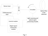
- Fig. 3 shows a schematic diagram of a structure exemplified in a specific application situation in combination with the detection state as described in the Embodiment 1 of the present disclosure.
- the control module in the exemplified solution further includes a digital signal processing module.
- the digital signal processing module is connected with the light receiving and optical signal processing module, in order to analyze distal information of the optical fiber according to the related information of the Rayleigh backscattered light and/or the Fresnel reflection light, and to feed back distal information of the optical fiber to the control module.
- the digital signal processing module can be embodied as a DSP, and a control core of the corresponding control module can be implemented by means of an FPGA, a single chip microcomputer or a PC.
- Fig. 4 it is an improvement solution further proposed to implement a design idea of an embodiment of the present disclosure to improve the interaction efficiency and to help an operator to directly obtain effective information from the detection device proposed in the embodiment of the present disclosure, without externally connecting other equipment, wherein the detection device further comprises a display.
- the display is connected with the digital signal processing module or the controller and is used for displaying an analysis result of the detection device.
- a cascaded Raman fiber laser has advantages of being long in gain medium, low in noise, wide in tuning range, capable of simultaneously realizing multi-wavelength output, and high in coupling efficiency with optical fibers and the like.
- the cascaded Raman fiber laser is used for pumping a fiber Raman amplifier to realize flat amplification in a wide bandwidth, and is an ideal pumping source for the fiber Raman amplifier.
- a multi-wavelength output cascaded Raman fiber laser is used as a signal source of the fiber communication system, especially the wavelength division multiplexing system, which can reduce a number of lasers at the emitting terminal. Therefore, the Raman laser can further be implemented in a cascaded manner in combination with embodiments of the present disclosure.
- Embodiment 2 of the present disclosure After providing a detection device for high-dynamic-range optical time domain reflection described in Embodiment 1, Embodiment 2 of the present disclosure also proposes a detection method for high-dynamic-range optical time domain reflection, wherein basic connection characteristics need to be realized in the detection method, and a control module is used for controlling a working state of a Raman laser and an OTDR detection laser, and is further used for obtaining an optical signal reflected from an optical fiber to be detected (compared with the connection characteristics mentioned above, it can be seen that the corresponding detection method of the present disclosure can also be implemented by the detection device described in Embodiment 1). As shown in Fig. 5 , the detection method comprises following steps:
- a Raman laser and an OTDR detection laser send Raman pulse laser and an OTDR detection optical signal to the optical fiber to be detected according to a preset configuration parameter.
- Step 202 in one detection period of the OTDR detection optical signal, the control module controls the Raman laser to send the Raman pulse laser again to the optical fiber to be detected if light intensity of returned Rayleigh backscattered light and/or Fresnel reflection light detected in a preset time period is less than a preset threshold.
- the forward Raman optical pulse amplify the detection optical pulse, but also can a plurality of Raman optical pulses be continuously sent through the Raman laser after the OTDR detection laser is closed to directly amplify the Rayleigh backscattered optical signal and/or the Fresnel reflection optical signal generated by the detection optical signal.
- a pulse width of the optical pulses sent by the Raman laser and a time interval between the optical pulses may be equal or unequal.
- the specific number of pulses, the width of each pulse, and the time interval between various pulses can be adjusted according to the power level of the optical signal actually received by the light receiving and optical signal processing module, so as to achieve a better result.
- the above-mentioned parameters can be obtained through the amplification principle of the existing Raman laser and a plurality of test experiments in the implementation of the present disclosure, and will not be repeated here.
- One detection period of the OTDR detection optical signal is determined according to one or more of a number of nodes on the optical fiber to be detected, a bandwidth of the detection optical signal and a processing speed of the control module, wherein the number of nodes in the optical fiber is represented as a branch, a relay and the like, which could increase the complexity of the analysis to a certain extent.
- the preset time period is within Mms after the OTDR detection optical signal is emitted in a current round of detection period, where said Mms takes a value from an interval [0, N/2], and M and N are corresponding time parameter values.
- the principle thereof is that the reflected optical signal in MmS time period is not used for analyzing the node problem existing in the optical fiber to be detected, but is only used for judging the attenuation condition of the reflected optical signal; and correspondingly, the reason why the Raman pulse laser is not emitted during the [M, N] time period is to prevent the emitted light generated by the emitted Raman pulse laser from affecting a process that the control module normally analyzes the reflected optical signal and parses the node problem existing in the optical fiber to be detected.
- the detection optical signal when performing the normal analysis for the reflected optical signal, it will firstly determine whether the detection optical signal is emitted into the optical fiber to be detected to form the reflection light, and whether its linearity factor reaches a preset threshold (e.g. -0.95), if it reaches the preset threshold, it shows that the influence of the Raman pulse optical signal on the reflected optical signal can be ignored.
- a preset threshold e.g. -0.95
- the Raman optical pulses should not be sent within 1ms to 4ms after one detection pulse is sent. If the Raman laser is made to continuously emit light, generated huge noise will negatively affect the signal-to-noise ratio, thus reducing the dynamic range of the OTDR.
- the preset threshold in addition to the detection period feature of the OTDR detection optical signal as explained above, there is another key technical element, i.e. the preset threshold, which will be described in more detail below.
- the preset threshold is more accurately expressed as a parameter value obtained through calculation according to a preset condition or a preset stipulation. Specifically, the preset threshold is obtained through calculation according to a calculation condition that the optical power of the obtained Rayleigh backscattered light and/or Fresnel reflection light is reduced by 3-5dB from the highest value initially received within one detection period of the OTDR detection optical signal. In the design and testing process of the experiment solution, it is concluded that 3dB is preferred.
- An example of the present disclosure combines the detection method as described in the Embodiment 2 and the detection device as described in the Embodiment 1, and provides a method of how to specifically implement the method as described in the Embodiment 2 by means of the detection device as described in the Embodiment 1. As shown in Fig. 6 , the method comprises:
- Step 301 multiplexing output signals of the Raman laser and the OTDR laser through the WDM and then entering the optical fiber to be detected through the circulator; connecting the circulator with the light receiving and optical signal processing module to convert the returned optical signal into a digital electric signal, and then connecting the output signals to the digital signal processor processing module and a display screen.
- the light receiving and optical signal processing module should include a filter, an avalanche photodiode (APD), an amplifier, an analog-to-digital converter and the like.
- the filter can filter out noises in the returned light, the APD converts the optical signal into an electrical signal, and the analog electrical signal is converted into the digital electric signal by an analog-to-digital converter after being amplified by the amplifier.
- Step 302 sending, by the control module, a driving signal to the OTDR laser to make the OTDR laser send a detection optical pulse, obtaining measurement information of a proximal end of the optical fiber through the light receiving and optical signal processing module and the digital signal processing module.
- Step 303 sending, by the control module, a driving signal to the OTDR laser to make the OTDR laser send detection optical pulses, and sending, by the control module, a driving signal to the Raman laser to continuously send a plurality of amplified optical pulses.
- a next Raman optical pulse should be sent when the signal optical power received by the light receiving and optical signal processing module is reduced to a certain level.
- the Rayleigh backscattered power received by the light receiving and optical signal processing module which is reduced by 3dB from the highest value, serves as a reference for sending the next Raman optical pulse.
- the pulse width of the Raman optical pulse should not be too long and the number of the Raman optical pulse should not be too large, in order to avoid affecting the normal sending of next round of detection pulse.
- a quarter of the time interval between two adjacent detection optical pulses is used as a mark to stop sending the Raman optical pulse.
- the control module can be realized by using FPGA-like devices.
- the measurement information of a distal end of the optical fiber can be obtained through the light receiving and optical signal processing module and the digital signal processing module. In actual operation, there is no sequence requirement for Step 302 and Step 303, i.e. the Raman laser can be closed firstly to measure the proximal end of the optical fiber, or the Raman laser can be driven firstly to measure the distal end of the optical fiber.
- Step 304 performing an integration analysis of the measurement information of the distal optical fiber and the measurement information of the proximal optical fiber to obtain a measurement result of the full section of optical fiber and be shown on the display, as shown in Fig. 8 .
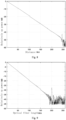
- Fig. 8 an optical fiber tail end reflection event at a distance of up to 245km is also clearly displayed.
- the dynamic range of the OTDR has exceeded 51dB.
- the measurement results can be processed by means of a digital signal processing algorithm such as de-noising and event recognition, thus the events occurring on the optical fiber can be judged more clearly and accurately.
- the frequency difference between adjacent multi-stage lasers should be kept at about 13THz (e.g. 12THz-13THz), correspondingly, in the multi-stage Raman laser, the longer the wavelength of the laser is, the higher the rated power set for the laser will be.
- control module can select an FPGA or similar device as its main device
- digital signal processing module can select an DSP or similar device as its main device
- the width of the detection optical pulse in Step 301 may be less than that of the detection optical pulse in step 302 to ensure the resolution of nearby measurement result.
- the widest pulse width should not be greater than 20 ⁇ s.
Landscapes
- Physics & Mathematics (AREA)
- Electromagnetism (AREA)
- Engineering & Computer Science (AREA)
- Computer Networks & Wireless Communication (AREA)
- Signal Processing (AREA)
- Optics & Photonics (AREA)
- Chemical & Material Sciences (AREA)
- Analytical Chemistry (AREA)
- General Physics & Mathematics (AREA)
- Investigating, Analyzing Materials By Fluorescence Or Luminescence (AREA)
- Optical Modulation, Optical Deflection, Nonlinear Optics, Optical Demodulation, Optical Logic Elements (AREA)
Description
- The present disclosure relates to the technical field of optical time domain reflectometer (OTDR), in particular to a detection method and device for high-dynamic-range optical time domain reflection.
- Currently, the communication networks of various countries in the world mainly use optical fibers as a transmission basis. The OTDR is usually used for testing characteristics of optical fiber when constructing and maintaining optical cable lines, and is also an important device of an on-line monitoring system in an optical communication network. A dynamic range is one of important technical indexes of the OTDR. The larger the dynamic range of OTDR is, the longer the distance of the optical communication line can be monitored.
- The working principle of OTDR is to analyze characteristics of a length, an attenuation, an event and the like of the optical fiber by detecting an energy distribution curve over time of Rayleigh backscattered light of pulse laser in the optical fiber line. When the OTDR emits one detection optical pulse to an optical fiber to be detected, the detection optical pulse will generate Rayleigh backscattered light while transmitting forward in the optical fiber. Fresnel reflection light will also be generated when a reflection type of event occurs. Continuously sampling these returned signals at high speed can obtain a measurement curve reflecting the characteristics of fiber attenuation, fault and the like by means of changes of signal power. The dynamic range determines a largest fiber length that can be measured by the OTDR.
- The dynamic range is closely related to a signal-to-noise ratio. When the signal-to-noise ratio is too low, effective information is overwhelmed by noises and cannot be obtained. The signal-to-noise ratio is conventionally improved by selecting a laser with higher power. However, due to limitations of process level, the power of a single laser may not be increased indefinitely, and too high laser power may cause nonlinearity in the optical fiber, thus affecting the performance of OTDR. Therefore, how to further improve the dynamic range after selecting a laser with a high power has high research value.
-
U.S. Patent No. 9,494,484 -
Chinese Patent Application No. 201611144348.3 - The technical problem to be solved in embodiments of the present disclosure is how to increase the dynamic range detected by the OTDR, thus increasing the distance of the optical fiber detected by the OTDR.
- Preferred embodiments of the present disclosure are provided as defined in the appended claims, by which the protection scope is to be set.
- Compared with the prior art, the beneficial effects of the embodiments of the present disclosure are as follows:
- According to the multi-pulse solution proposed by the present disclosure, not only can the detection optical pulse be amplified via the forward Raman optical pulse, but also can a plurality of Raman optical pulses be continuously sent via the Raman laser after the OTDR detection laser is closed, to directly amplify the Rayleigh backscattered optical signal and/or the Fresnel reflection optical signal generated by the detection optical pulse.
- According to the principle of Raman amplifier, the transferring direction of the Raman optical pulse in the optical fiber is opposite to that of the Rayleigh backscattered optical signal, but it can still produce an amplification effect to the Rayleigh backscattered optical signal. Measurement of ultra-long-distance optical fiber is ensured through the solution proposed by the present disclosure, i.e. when the Rayleigh backscattered optical signal received by the receiver is lower than a certain level, a next Raman optical pulse is sent to amplify the Rayleigh backscattered optical signal in order to maintain the power of the Rayleigh backscattered optical signal and/or the Fresnel reflection optical signal always at a relatively high level at a front end of the optical fiber.
- Compared with the solution of the
U.S. Patent No. 9,494,484 U.S. Patent No. 9,494,484 - In order to more clearly explain the technical solutions of the embodiments of the present disclosure or technical solutions in the prior art, the following will briefly introduce drawings that need to be used in the description of the embodiments or the prior art, and obviously, the drawings in the following description are only some embodiments of the present disclosure, and for those ordinary skill in the art, other drawings can be obtained based on these drawings without inventive labor.
-
Fig. 1 is a schematic structural diagram of a detection device for high-dynamic-range optical time domain reflection provided by an embodiment of the present disclosure. -
Fig. 2 is a schematic diagram of structural layout of a circulator described in an embodiment of the present disclosure. -
Fig. 3 is a more detailed schematic structural diagram of a detection device for high-dynamic-range optical time domain reflection in an example occasion provided by an embodiment of the present disclosure. -
Fig. 4 is a schematic structural diagram of a detection device for high-dynamic-range optical time domain reflection with an extended functional module provided by an embodiment of the present disclosure. -
Fig. 5 is a flow schematic diagram of a detection method for high-dynamic-range optical time domain reflection provided by an embodiment of the present disclosure. -
Fig. 6 is a flow schematic diagram of a detection method for high-dynamic-range optical time domain reflection in a specific example environment provided by an embodiment of the present disclosure. -
Fig. 7 is a measurement result diagram under a condition that light is continuously emitted from the Raman laser provided by an embodiment of the present disclosure. -
Fig. 8 is a measurement result diagram obtained by using a detection method provided by an embodiment of the present disclosure. -
Fig. 9 is a measurement result diagram obtained by using a detection method of an embodiment of the present disclosure and provided by the embodiment of the present disclosure. - In order to make the objects, technical solutions and advantages of the present disclosure more obvious, the present disclosure is further described in detail below with reference to the drawings and embodiments. It should be noted that the specific embodiments described herein are only for explaining but not for limiting the present disclosure.
- In the description of the present disclosure, orientations or positional relationships indicated by terms "inside", "outside", "longitudinal", "horizontal", "upper", "lower", "top", "bottom" and the like are based on the orientations or positional relationships shown in the drawings and merely for the convenience of describing the present disclosure, not requiring that any apparatus or method in the present disclosure must be constructed and operated in a specific orientation disclosed in the present disclosure, therefore should not be understood as a limitation to the present disclosure in any way.
- In addition, the technical features involved in various embodiments of the present disclosure described below may be combined with each other as long as they are not in conflict with each other.
- Embodiment 1 of the present disclosure provides a detection device for high-dynamic-range optical time domain reflection, as shown in
Fig. 1 , comprising a Raman laser, an OTDR detection laser, a Wavelength Division Multiplexing (WDM), a control module, a light receiving and optical signal processing module, and a circulator. - The Raman laser and the OTDR detection laser are respectively connected with the WDM, a light outlet of which is connected with a light inlet of the circulator (when the circulator used in the device in
Fig. 1 is separately extracted to show an interface distribution thereof, the corresponding distribution structure is shown inFig. 2 ), and pulse light emitted by the Raman laser and the OTDR detection laser is multiplexed by the WDM and then enters an optical fiber to be detected through an I/O optical port of the circulator (as shown inFig. 2 ). - The light receiving and optical signal processing module is connected with a light outlet of the circulator to obtain Rayleigh backscattered light and/or Fresnel reflection light returned from the optical fiber to be detected, and is also connected with the control module to send related information of reflection light to the control module.
- The light receiving and optical signal processing module has an optical filtering function and a circuit filtering function, which are used to perform a photoelectric conversion and a noise filtering processing on the received reflection optical signal, and send related information of processed reflection light to the control module, wherein the related information of reflection light includes: optical power intensity, light intensity distribution, receiving time and the like of the Rayleigh backscattered light and/or Fresnel reflection light.
- The control module is used for controlling a driving pin of the Raman laser, and controlling the Raman laser to emit at least two optical pulses with a time interval within one detection time period according to the related information of reflection light.
- According to the multi-pulse solution provided by the embodiment of the present disclosure, not only can the detection optical pulses be amplified by a forward Raman optical pulse, but also can the Rayleigh backscattered optical signal and/or the Fresnel reflection optical signal generated by the detection optical pulse be directly amplified via a plurality of Raman optical pulses continuously sent through the Raman laser after the OTDR detection laser is closed.
- The Raman optical pulse transfers in the optical fiber in a direction opposite to that of the Rayleigh backscattered optical signal, but it can still amplify the Rayleigh backscattered optical signal. Measurement of ultra-long-distance optical fiber is ensured through the solution provided by the present disclosure, i.e. when the Rayleigh backscattered optical signal received by the light receiving and optical signal processing module is lower than a certain level, a next Raman optical pulse is sent for amplifying the Rayleigh backscattered optical signal to maintain power of the Rayleigh backscattered optical signal and/or the Fresnel reflection optical signal always at a relatively high level at a front end of the optical fiber.
-
Fig. 3 shows a schematic diagram of a structure exemplified in a specific application situation in combination with the detection state as described in the Embodiment 1 of the present disclosure. Compared with the structure described in the Embodiment 1, the control module in the exemplified solution further includes a digital signal processing module. - The digital signal processing module is connected with the light receiving and optical signal processing module, in order to analyze distal information of the optical fiber according to the related information of the Rayleigh backscattered light and/or the Fresnel reflection light, and to feed back distal information of the optical fiber to the control module. The digital signal processing module can be embodied as a DSP, and a control core of the corresponding control module can be implemented by means of an FPGA, a single chip microcomputer or a PC.
- As shown in
Fig. 4 , it is an improvement solution further proposed to implement a design idea of an embodiment of the present disclosure to improve the interaction efficiency and to help an operator to directly obtain effective information from the detection device proposed in the embodiment of the present disclosure, without externally connecting other equipment, wherein the detection device further comprises a display. - The display is connected with the digital signal processing module or the controller and is used for displaying an analysis result of the detection device.
- A cascaded Raman fiber laser has advantages of being long in gain medium, low in noise, wide in tuning range, capable of simultaneously realizing multi-wavelength output, and high in coupling efficiency with optical fibers and the like. The cascaded Raman fiber laser is used for pumping a fiber Raman amplifier to realize flat amplification in a wide bandwidth, and is an ideal pumping source for the fiber Raman amplifier. A multi-wavelength output cascaded Raman fiber laser is used as a signal source of the fiber communication system, especially the wavelength division multiplexing system, which can reduce a number of lasers at the emitting terminal. Therefore, the Raman laser can further be implemented in a cascaded manner in combination with embodiments of the present disclosure.
- After providing a detection device for high-dynamic-range optical time domain reflection described in Embodiment 1, Embodiment 2 of the present disclosure also proposes a detection method for high-dynamic-range optical time domain reflection, wherein basic connection characteristics need to be realized in the detection method, and a control module is used for controlling a working state of a Raman laser and an OTDR detection laser, and is further used for obtaining an optical signal reflected from an optical fiber to be detected (compared with the connection characteristics mentioned above, it can be seen that the corresponding detection method of the present disclosure can also be implemented by the detection device described in Embodiment 1). As shown in
Fig. 5 , the detection method comprises following steps: - in
Step 201, a Raman laser and an OTDR detection laser send Raman pulse laser and an OTDR detection optical signal to the optical fiber to be detected according to a preset configuration parameter. - in
Step 202, in one detection period of the OTDR detection optical signal, the control module controls the Raman laser to send the Raman pulse laser again to the optical fiber to be detected if light intensity of returned Rayleigh backscattered light and/or Fresnel reflection light detected in a preset time period is less than a preset threshold. - According to the multi-pulse solution provided by the embodiment of the present disclosure, not only can the forward Raman optical pulse amplify the detection optical pulse, but also can a plurality of Raman optical pulses be continuously sent through the Raman laser after the OTDR detection laser is closed to directly amplify the Rayleigh backscattered optical signal and/or the Fresnel reflection optical signal generated by the detection optical signal.
- In embodiments of the present disclosure, a pulse width of the optical pulses sent by the Raman laser and a time interval between the optical pulses may be equal or unequal. The specific number of pulses, the width of each pulse, and the time interval between various pulses can be adjusted according to the power level of the optical signal actually received by the light receiving and optical signal processing module, so as to achieve a better result. The above-mentioned parameters can be obtained through the amplification principle of the existing Raman laser and a plurality of test experiments in the implementation of the present disclosure, and will not be repeated here.
- In order to further provide a technical idea of how the embodiments of the present disclosure to be implemented in a specific application scene, a concept of the detection period of the OTDR detection optical signal proposed in the embodiments of the present disclosure could more clearly explain and define the detection period of the OTDR detection optical signal. One detection period of the OTDR detection optical signal is determined according to one or more of a number of nodes on the optical fiber to be detected, a bandwidth of the detection optical signal and a processing speed of the control module, wherein the number of nodes in the optical fiber is represented as a branch, a relay and the like, which could increase the complexity of the analysis to a certain extent. When said one detection period of the OTDR detection optical signal is specifically Nms, the preset time period is within Mms after the OTDR detection optical signal is emitted in a current round of detection period, where said Mms takes a value from an interval [0, N/2], and M and N are corresponding time parameter values. The principle thereof is that the reflected optical signal in MmS time period is not used for analyzing the node problem existing in the optical fiber to be detected, but is only used for judging the attenuation condition of the reflected optical signal; and correspondingly, the reason why the Raman pulse laser is not emitted during the [M, N] time period is to prevent the emitted light generated by the emitted Raman pulse laser from affecting a process that the control module normally analyzes the reflected optical signal and parses the node problem existing in the optical fiber to be detected. Under normal circumstances, when performing the normal analysis for the reflected optical signal, it will firstly determine whether the detection optical signal is emitted into the optical fiber to be detected to form the reflection light, and whether its linearity factor reaches a preset threshold (e.g. -0.95), if it reaches the preset threshold, it shows that the influence of the Raman pulse optical signal on the reflected optical signal can be ignored. In terms of a set of parameters, when the detection period of the OTDR detection optical signal is 4ms±1s, the preset time period is specifically within 1±0.2ms after the OTDR detection optical signal is sent. For example, if the time interval between two detection pulses is 4ms, the Raman optical pulses should not be sent within 1ms to 4ms after one detection pulse is sent. If the Raman laser is made to continuously emit light, generated huge noise will negatively affect the signal-to-noise ratio, thus reducing the dynamic range of the OTDR.
- In the embodiments of the present disclosure, in addition to the detection period feature of the OTDR detection optical signal as explained above, there is another key technical element, i.e. the preset threshold, which will be described in more detail below.
- The preset threshold is more accurately expressed as a parameter value obtained through calculation according to a preset condition or a preset stipulation. Specifically, the preset threshold is obtained through calculation according to a calculation condition that the optical power of the obtained Rayleigh backscattered light and/or Fresnel reflection light is reduced by 3-5dB from the highest value initially received within one detection period of the OTDR detection optical signal. In the design and testing process of the experiment solution, it is concluded that 3dB is preferred.
- Example, which does not fall within the scope of the appended claims:
An example of the present disclosure combines the detection method as described in the Embodiment 2 and the detection device as described in the Embodiment 1, and provides a method of how to specifically implement the method as described in the Embodiment 2 by means of the detection device as described in the Embodiment 1. As shown inFig. 6 , the method comprises: -
Step 301, multiplexing output signals of the Raman laser and the OTDR laser through the WDM and then entering the optical fiber to be detected through the circulator; connecting the circulator with the light receiving and optical signal processing module to convert the returned optical signal into a digital electric signal, and then connecting the output signals to the digital signal processor processing module and a display screen. - The light receiving and optical signal processing module should include a filter, an avalanche photodiode (APD), an amplifier, an analog-to-digital converter and the like. The filter can filter out noises in the returned light, the APD converts the optical signal into an electrical signal, and the analog electrical signal is converted into the digital electric signal by an analog-to-digital converter after being amplified by the amplifier.
-
Step 302, sending, by the control module, a driving signal to the OTDR laser to make the OTDR laser send a detection optical pulse, obtaining measurement information of a proximal end of the optical fiber through the light receiving and optical signal processing module and the digital signal processing module. -
Step 303, sending, by the control module, a driving signal to the OTDR laser to make the OTDR laser send detection optical pulses, and sending, by the control module, a driving signal to the Raman laser to continuously send a plurality of amplified optical pulses. - In order to achieve a better effect, a next Raman optical pulse should be sent when the signal optical power received by the light receiving and optical signal processing module is reduced to a certain level. In the embodiments described in the present specification, the Rayleigh backscattered power received by the light
receiving and optical signal processing module which is reduced by 3dB from the highest value, serves as a reference for sending the next Raman optical pulse. At the same time, the pulse width of the Raman optical pulse should not be too long and the number of the Raman optical pulse should not be too large, in order to avoid affecting the normal sending of next round of detection pulse. In the embodiments of the present disclosure, a quarter of the time interval between two adjacent detection optical pulses is used as a mark to stop sending the Raman optical pulse. That is, if the time interval between two detection pulses is 4ms, no Raman optical pulse should be sent within 1ms to 4ms after one detection pulse is sent. If the Raman laser is continuously made to emit light, the generated huge noise will negatively affect the signal-to-noise ratio, thus reducing the dynamic range of the OTDR (as shown inFig. 7 , the dynamic range thereof is about 15dB). The control module can be realized by using FPGA-like devices. The measurement information of a distal end of the optical fiber can be obtained through the light receiving and optical signal processing module and the digital signal processing module. In actual operation, there is no sequence requirement forStep 302 andStep 303, i.e. the Raman laser can be closed firstly to measure the proximal end of the optical fiber, or the Raman laser can be driven firstly to measure the distal end of the optical fiber. -
Step 304, performing an integration analysis of the measurement information of the distal optical fiber and the measurement information of the proximal optical fiber to obtain a measurement result of the full section of optical fiber and be shown on the display, as shown inFig. 8 . InFig. 8 , an optical fiber tail end reflection event at a distance of up to 245km is also clearly displayed. According to the definition of single-pass RMS dynamic range in IEC61746-2009, the dynamic range of the OTDR has exceeded 51dB. Compared with the obtained measurement results shown inFig. 9 without the Raman amplifier under the same condition, the dynamic range has been significantly improved. Furthermore, before the measurement results are displayed on the display, the measurement results can be processed by means of a digital signal processing algorithm such as de-noising and event recognition, thus the events occurring on the optical fiber can be judged more clearly and accurately. - In the multi-stage Raman laser in the embodiments of the present disclosure, the frequency difference between adjacent multi-stage lasers should be kept at about 13THz (e.g. 12THz-13THz), correspondingly, in the multi-stage Raman laser, the longer the wavelength of the laser is, the higher the rated power set for the laser will be.
- In the embodiment of the present disclosure, the control module can select an FPGA or similar device as its main device, and the digital signal processing module can select an DSP or similar device as its main device.
- In implementing the present disclosure, the width of the detection optical pulse in
Step 301 may be less than that of the detection optical pulse instep 302 to ensure the resolution of nearby measurement result. In order to meet the basic resolution requirement, the widest pulse width should not be greater than 20µs. - It should be noted that since the detection device embodiment 1 and the detection method embodiment 2 of the present disclosure are based on the same concept, the specific content thereof can be mutual reference, and will not be repeated here.
- The above description is only the preferred embodiments of the present disclosure and is not intended to limit the present disclosure.
Claims (10)
- A detection device for high-dynamic-range optical time domain reflection, comprising a Raman laser, an OTDR detection laser, a wavelength division multiplexer WDM, a control module, a light receiving and optical signal processing module, and a circulator,wherein the Raman laser and the OTDR detection laser are respectively connected with the WDM, a light outlet of which is connected with a light inlet of the circulator, and Raman pulse laser emitted by the Raman laser and pulse light emitted by the OTDR detection laser are multiplexed by the WDM and then enter an optical fiber to be detected via an I/O optical port of the circulator;wherein the light receiving and optical signal processing module is connected with a light outlet of the circulator to obtain Rayleigh backscattered light and/or Fresnel reflected light returned from the optical fiber to be detected;wherein the light receiving and optical signal processing module is also connected with the control module to send related information of reflection light to the control module;wherein the control module is connected to a driving pin of the Raman laser to control the Raman laser to emit, according to the related information of reflection light, at least two optical pulses with a time interval within one detection time period,characterized in that the control module is used to control the Raman laser to send Raman pulse laser again to the optical fiber to be detected, if light intensity of the returned Rayleigh backscattered light and/or Fresnel reflection light detected in a preset time period within one detection period of the pulse light emitted by the OTDR detection laser is less than a preset threshold; andwherein when said one detection period of the pulse light emitted by the OTDR detection laser is specifically Nms, the preset time period is Mms after the OTDR detection laser emits the pulse light in a current detection period, where said Mms takes a value from an interval [0, N/2], M and N are corresponding time parameter values.
- The detection device for high-dynamic-range optical time domain reflection of claim 1, characterized in that
the control module includes a digital signal processing module, wherein the digital signal processing module is connected with the light receiving and optical signal processing module, to analyze information of a far end of the optical fiber according to related information of the Rayleigh backscattered light and/or Fresnel reflection light and to feed back the information of the far end of the optical fiber to the control module. - The detection device for high-dynamic-range optical time domain reflection of claim 2, characterized in that
the control module is specifically an FPGA, a single chip microcomputer or a microprocessor; and the digital signal processing module is specifically a DSP. - The detection device for high-dynamic-range optical time domain reflection according to any one of claims 1 to 3, characterized in that,
the detection device further comprises a display, wherein the display is connected with the digital signal processing module or the control module, and is used for displaying an analysis result of the detection device. - The detection device for high-dynamic-range optical time domain reflection according to any one of claims 1 to 3, characterized in that the Raman laser is specifically a cascade Raman laser composed of at least two stages.
- The detection device for high-dynamic-range optical time domain reflection of claim 5, characterized in that a frequency difference of each stage of the Raman laser from the cascade Raman laser is 12THz-13THz.
- A detection method for high-dynamic-range optical time domain reflection, wherein a control module is used for controlling a working state of a Raman laser and an OTDR detection laser, and is further used for obtaining an optical signal reflected from an optical fiber to be detected, andthe detection method comprises:sending (201), Raman pulse laser by the Raman laser and pulse light by the OTDR detection laser to the optical fiber to be detected according to a preset configuration parameter;characterized in that the detection method further comprises:sending (202), by the Raman laser controlled by the control module, Raman pulse laser again to the optical fiber to be detected, if light intensity of returned Rayleigh backscattered light and/or Fresnel reflection light detected in a preset time period within one detection period of the pulse light emitted by the OTDR detection laser is less than a preset threshold;wherein when said one detection period of the pulse light emitted by the OTDR detection laser is specifically Nms, the preset time period is Mms after the OTDR detection laser emits the pulse light in a current detection period, where said Mms takes a value from an interval [0, N/2], and M and N are corresponding time parameter values.
- The detection method for high-dynamic-range optical time domain reflection of claim 7, characterized in that
Said one detection period of the pulse light emitted by the OTDR detection laser is determined by one or more of a number of nodes in the optical fiber to be detected, a bandwidth of the pulse light emitted by the OTDR detection laser and a processing speed of the control module. - The detection method for high-dynamic-range optical time domain reflection of claim 7, characterized in that
when the detection period of the pulse light emitted by the OTDR detection laser is 4ms±1s, the preset time period is specifically within 1±0.2ms after the OTDR detection laser sent the pulse light. - The detection method for high-dynamic-range optical time domain reflection of claim 7, characterized in that
the preset threshold is obtained through calculation according to a calculation condition that an optical power of obtained Rayleigh backscattered light and/or Fresnel reflection light is reduced by 3-5dB from a highest value initially received within one detection period of the pulse light emitted by the OTDR detection laser.
Applications Claiming Priority (2)
| Application Number | Priority Date | Filing Date | Title |
|---|---|---|---|
| CN201810191046.4A CN108199767B (en) | 2018-03-08 | 2018-03-08 | A high dynamic range optical time domain reflectometry detection method and device |
| PCT/CN2018/123408 WO2019169934A1 (en) | 2018-03-08 | 2018-12-25 | Detection method and device for high-dynamic-range optical time domain reflection |
Publications (3)
| Publication Number | Publication Date |
|---|---|
| EP3764566A1 EP3764566A1 (en) | 2021-01-13 |
| EP3764566A4 EP3764566A4 (en) | 2021-12-15 |
| EP3764566B1 true EP3764566B1 (en) | 2024-12-25 |
Family
ID=62595347
Family Applications (1)
| Application Number | Title | Priority Date | Filing Date |
|---|---|---|---|
| EP18908330.6A Active EP3764566B1 (en) | 2018-03-08 | 2018-12-25 | Detection method and device for high-dynamic-range optical time domain reflection |
Country Status (3)
| Country | Link |
|---|---|
| EP (1) | EP3764566B1 (en) |
| CN (1) | CN108199767B (en) |
| WO (1) | WO2019169934A1 (en) |
Families Citing this family (12)
| Publication number | Priority date | Publication date | Assignee | Title |
|---|---|---|---|---|
| CN108199767B (en) * | 2018-03-08 | 2020-06-30 | 武汉光迅科技股份有限公司 | A high dynamic range optical time domain reflectometry detection method and device |
| CN108649416B (en) * | 2018-06-27 | 2019-09-13 | 武汉光迅科技股份有限公司 | Method and device for obtaining influence factor of fiber length on maximum gain in a distributed Raman fiber amplifier |
| CN110715790A (en) * | 2018-07-13 | 2020-01-21 | 中兴通讯股份有限公司 | Pulse testing method and device, testing equipment and storage medium |
| CN111595241B (en) * | 2019-02-21 | 2021-05-25 | 中兴通讯股份有限公司 | Optical fiber monitoring method and device |
| CN110174242B (en) * | 2019-05-23 | 2021-04-06 | 长飞光纤光缆股份有限公司 | Device and method for eliminating laser wavelength drift error by optical time domain reflectometer |
| CN121917192A (en) | 2020-04-23 | 2026-04-24 | 珠海保税区光联通讯技术有限公司 | Light integration device and light time domain reflectometer |
| CN112054839B (en) * | 2020-08-11 | 2022-06-10 | 武汉光迅科技股份有限公司 | OTDR (optical time Domain reflectometer), test system, test method and storage medium |
| CN113764966A (en) * | 2021-08-24 | 2021-12-07 | 武汉光迅科技股份有限公司 | Raman amplifier and its control method, device and storage medium |
| CN117639911A (en) * | 2022-08-12 | 2024-03-01 | 华为技术有限公司 | OTDR and fiber optic communication systems |
| US20240068905A1 (en) * | 2022-08-25 | 2024-02-29 | Ii-Vi Delaware, Inc. | Pluggable Optical Time Domain Reflectometer |
| CN119254313B (en) * | 2024-10-30 | 2025-07-29 | 中国人民解放军国防科技大学 | Optical time domain reflectometer based on high gain optical pulse receiving and transmitting |
| CN119921850B (en) * | 2024-12-31 | 2025-10-31 | 武汉邮电科学研究院有限公司 | An optical time-domain reflectometer, a signal generation method, an apparatus, a device, and a medium. |
Family Cites Families (11)
| Publication number | Priority date | Publication date | Assignee | Title |
|---|---|---|---|---|
| JP4101024B2 (en) * | 2002-11-06 | 2008-06-11 | 富士通株式会社 | Loss point presence / absence determination method and distributed Raman amplification apparatus using the same |
| CN202177385U (en) * | 2011-08-09 | 2012-03-28 | 中国计量学院 | Ultra-long-range fully-distributed type optical Rayleigh and Raman scattering sensor of pulse coding |
| CN102706437B (en) * | 2012-06-13 | 2014-10-22 | 扬州森斯光电科技有限公司 | Super-long distance phase-sensitive optical time domain reflectometer (Phi-OTDR) system |
| CN202710286U (en) * | 2012-09-06 | 2013-01-30 | 杭州欧忆光电科技有限公司 | Time domain reflectometer fused with Raman amplifier |
| CN103199920B (en) * | 2013-04-02 | 2016-06-08 | 上海波汇科技股份有限公司 | A kind of light time domain reflectometer system |
| CN103323215B (en) * | 2013-05-20 | 2015-11-25 | 中国电子科技集团公司第四十一研究所 | A kind of light time domain reflection measuring apparatus and method |
| CN203522742U (en) * | 2013-09-04 | 2014-04-02 | 华为技术有限公司 | Optical fiber Raman amplification device |
| US9494484B2 (en) * | 2014-03-09 | 2016-11-15 | Ii-Vi Incorporated | In-service optical time domain reflectometry utilizing raman pump source |
| CN106452569B (en) * | 2016-12-13 | 2018-11-20 | 无锡市德科立光电子技术有限公司 | The OTDR optical amplification device and control method of prepare more part of common light source |
| CN107332101B (en) * | 2017-06-28 | 2019-07-26 | 武汉光迅科技股份有限公司 | It is a kind of can Dynamic Execution optical time domain reflection detection component and detection method |
| CN108199767B (en) * | 2018-03-08 | 2020-06-30 | 武汉光迅科技股份有限公司 | A high dynamic range optical time domain reflectometry detection method and device |
-
2018
- 2018-03-08 CN CN201810191046.4A patent/CN108199767B/en active Active
- 2018-12-25 EP EP18908330.6A patent/EP3764566B1/en active Active
- 2018-12-25 WO PCT/CN2018/123408 patent/WO2019169934A1/en not_active Ceased
Also Published As
| Publication number | Publication date |
|---|---|
| CN108199767A (en) | 2018-06-22 |
| CN108199767B (en) | 2020-06-30 |
| WO2019169934A1 (en) | 2019-09-12 |
| EP3764566A4 (en) | 2021-12-15 |
| EP3764566A1 (en) | 2021-01-13 |
Similar Documents
| Publication | Publication Date | Title |
|---|---|---|
| EP3764566A1 (en) | Detection method and device for high-dynamic-range optical time domain reflection | |
| CN107483106B (en) | An online optical time domain reflectometer structure, detection system and detection method | |
| EP2719094B1 (en) | Pon supervision using otdr measurements | |
| WO1991012509A1 (en) | Optical test apparatus | |
| CN107332101B (en) | It is a kind of can Dynamic Execution optical time domain reflection detection component and detection method | |
| CN103229433B (en) | A kind of optical line terminal, optical time domain reflectometer and signal transmit-receive method and system | |
| JP5291767B2 (en) | Fiber measuring device | |
| EP2741432A1 (en) | Optical time-domain reflectometer and method for obtaining measuring signals thereof | |
| CN101650197A (en) | Optical frequency domain reflection-based optical fiber sensor system | |
| US7099581B2 (en) | OTDR arrangement for detecting faults in an optical transmission system on a span by span basis | |
| CN201369727Y (en) | Optical line terminal | |
| CN104205676B (en) | Optical line terminal, optical transceiver module, system, and optical fiber detection method | |
| CN102324969B (en) | Receiving end light power on-line detection device and implementation method thereof | |
| CN106656317B (en) | OTDR optical amplifying device sharing light source and control method | |
| CN106160868B (en) | A kind of Raman Fiber Amplifier and its control method for realizing gain dynamic locking | |
| CN113108942A (en) | System and method for improving sampling resolution of Raman optical time domain reflectometer | |
| CN117692061A (en) | A real-time monitoring device and a dense wavelength division transmission system | |
| CN214667324U (en) | System for improving sampling resolution of Raman optical time domain reflectometer | |
| WO2020098277A1 (en) | Distributed optical fiber sensing system and control method and control device therefor, and storage medium | |
| US7230691B2 (en) | Photometer | |
| CN102868446B (en) | A kind of OLT optical module using couple APD to share booster circuit | |
| CN114337813A (en) | Optical performance monitoring method and system for asynchronous delay sampling and image processing | |
| CN100362780C (en) | Method and apparatus for monitoring wave divided multiplexing system to increase and reduce channel | |
| CN224216100U (en) | Signal processing device integrating DAS and BOTDR | |
| CN206575418U (en) | The OTDR optical amplification devices of common light source |
Legal Events
| Date | Code | Title | Description |
|---|---|---|---|
| STAA | Information on the status of an ep patent application or granted ep patent |
Free format text: STATUS: THE INTERNATIONAL PUBLICATION HAS BEEN MADE |
|
| PUAI | Public reference made under article 153(3) epc to a published international application that has entered the european phase |
Free format text: ORIGINAL CODE: 0009012 |
|
| STAA | Information on the status of an ep patent application or granted ep patent |
Free format text: STATUS: REQUEST FOR EXAMINATION WAS MADE |
|
| 17P | Request for examination filed |
Effective date: 20200930 |
|
| AK | Designated contracting states |
Kind code of ref document: A1 Designated state(s): AL AT BE BG CH CY CZ DE DK EE ES FI FR GB GR HR HU IE IS IT LI LT LU LV MC MK MT NL NO PL PT RO RS SE SI SK SM TR |
|
| AX | Request for extension of the european patent |
Extension state: BA ME |
|
| DAV | Request for validation of the european patent (deleted) | ||
| DAX | Request for extension of the european patent (deleted) | ||
| A4 | Supplementary search report drawn up and despatched |
Effective date: 20211117 |
|
| RIC1 | Information provided on ipc code assigned before grant |
Ipc: G01M 11/00 20060101ALI20211111BHEP Ipc: H01S 3/30 20060101ALI20211111BHEP Ipc: H04B 10/071 20130101AFI20211111BHEP |
|
| GRAP | Despatch of communication of intention to grant a patent |
Free format text: ORIGINAL CODE: EPIDOSNIGR1 |
|
| STAA | Information on the status of an ep patent application or granted ep patent |
Free format text: STATUS: GRANT OF PATENT IS INTENDED |
|
| INTG | Intention to grant announced |
Effective date: 20240730 |
|
| GRAS | Grant fee paid |
Free format text: ORIGINAL CODE: EPIDOSNIGR3 |
|
| GRAA | (expected) grant |
Free format text: ORIGINAL CODE: 0009210 |
|
| STAA | Information on the status of an ep patent application or granted ep patent |
Free format text: STATUS: THE PATENT HAS BEEN GRANTED |
|
| AK | Designated contracting states |
Kind code of ref document: B1 Designated state(s): AL AT BE BG CH CY CZ DE DK EE ES FI FR GB GR HR HU IE IS IT LI LT LU LV MC MK MT NL NO PL PT RO RS SE SI SK SM TR |
|
| REG | Reference to a national code |
Ref country code: GB Ref legal event code: FG4D |
|
| REG | Reference to a national code |
Ref country code: CH Ref legal event code: EP |
|
| REG | Reference to a national code |
Ref country code: DE Ref legal event code: R096 Ref document number: 602018078027 Country of ref document: DE |
|
| REG | Reference to a national code |
Ref country code: IE Ref legal event code: FG4D |
|
| REG | Reference to a national code |
Ref country code: LT Ref legal event code: MG9D |
|
| PG25 | Lapsed in a contracting state [announced via postgrant information from national office to epo] |
Ref country code: HR Free format text: LAPSE BECAUSE OF FAILURE TO SUBMIT A TRANSLATION OF THE DESCRIPTION OR TO PAY THE FEE WITHIN THE PRESCRIBED TIME-LIMIT Effective date: 20241225 |
|
| PG25 | Lapsed in a contracting state [announced via postgrant information from national office to epo] |
Ref country code: FI Free format text: LAPSE BECAUSE OF FAILURE TO SUBMIT A TRANSLATION OF THE DESCRIPTION OR TO PAY THE FEE WITHIN THE PRESCRIBED TIME-LIMIT Effective date: 20241225 |
|
| PG25 | Lapsed in a contracting state [announced via postgrant information from national office to epo] |
Ref country code: BG Free format text: LAPSE BECAUSE OF FAILURE TO SUBMIT A TRANSLATION OF THE DESCRIPTION OR TO PAY THE FEE WITHIN THE PRESCRIBED TIME-LIMIT Effective date: 20241225 |
|
| PG25 | Lapsed in a contracting state [announced via postgrant information from national office to epo] |
Ref country code: NO Free format text: LAPSE BECAUSE OF FAILURE TO SUBMIT A TRANSLATION OF THE DESCRIPTION OR TO PAY THE FEE WITHIN THE PRESCRIBED TIME-LIMIT Effective date: 20250325 |
|
| PG25 | Lapsed in a contracting state [announced via postgrant information from national office to epo] |
Ref country code: LV Free format text: LAPSE BECAUSE OF FAILURE TO SUBMIT A TRANSLATION OF THE DESCRIPTION OR TO PAY THE FEE WITHIN THE PRESCRIBED TIME-LIMIT Effective date: 20241225 Ref country code: GR Free format text: LAPSE BECAUSE OF FAILURE TO SUBMIT A TRANSLATION OF THE DESCRIPTION OR TO PAY THE FEE WITHIN THE PRESCRIBED TIME-LIMIT Effective date: 20250326 |
|
| PG25 | Lapsed in a contracting state [announced via postgrant information from national office to epo] |
Ref country code: RS Free format text: LAPSE BECAUSE OF FAILURE TO SUBMIT A TRANSLATION OF THE DESCRIPTION OR TO PAY THE FEE WITHIN THE PRESCRIBED TIME-LIMIT Effective date: 20250325 |
|
| REG | Reference to a national code |
Ref country code: NL Ref legal event code: MP Effective date: 20241225 |
|
| PG25 | Lapsed in a contracting state [announced via postgrant information from national office to epo] |
Ref country code: NL Free format text: LAPSE BECAUSE OF FAILURE TO SUBMIT A TRANSLATION OF THE DESCRIPTION OR TO PAY THE FEE WITHIN THE PRESCRIBED TIME-LIMIT Effective date: 20241225 |
|
| REG | Reference to a national code |
Ref country code: AT Ref legal event code: MK05 Ref document number: 1755055 Country of ref document: AT Kind code of ref document: T Effective date: 20241225 |
|
| PG25 | Lapsed in a contracting state [announced via postgrant information from national office to epo] |
Ref country code: SM Free format text: LAPSE BECAUSE OF FAILURE TO SUBMIT A TRANSLATION OF THE DESCRIPTION OR TO PAY THE FEE WITHIN THE PRESCRIBED TIME-LIMIT Effective date: 20241225 |
|
| PG25 | Lapsed in a contracting state [announced via postgrant information from national office to epo] |
Ref country code: PL Free format text: LAPSE BECAUSE OF FAILURE TO SUBMIT A TRANSLATION OF THE DESCRIPTION OR TO PAY THE FEE WITHIN THE PRESCRIBED TIME-LIMIT Effective date: 20241225 |
|
| PG25 | Lapsed in a contracting state [announced via postgrant information from national office to epo] |
Ref country code: ES Free format text: LAPSE BECAUSE OF FAILURE TO SUBMIT A TRANSLATION OF THE DESCRIPTION OR TO PAY THE FEE WITHIN THE PRESCRIBED TIME-LIMIT Effective date: 20241225 |
|
| PG25 | Lapsed in a contracting state [announced via postgrant information from national office to epo] |
Ref country code: IS Free format text: LAPSE BECAUSE OF FAILURE TO SUBMIT A TRANSLATION OF THE DESCRIPTION OR TO PAY THE FEE WITHIN THE PRESCRIBED TIME-LIMIT Effective date: 20250425 |
|
| PG25 | Lapsed in a contracting state [announced via postgrant information from national office to epo] |
Ref country code: PT Free format text: LAPSE BECAUSE OF FAILURE TO SUBMIT A TRANSLATION OF THE DESCRIPTION OR TO PAY THE FEE WITHIN THE PRESCRIBED TIME-LIMIT Effective date: 20250428 |
|
| PG25 | Lapsed in a contracting state [announced via postgrant information from national office to epo] |
Ref country code: EE Free format text: LAPSE BECAUSE OF FAILURE TO SUBMIT A TRANSLATION OF THE DESCRIPTION OR TO PAY THE FEE WITHIN THE PRESCRIBED TIME-LIMIT Effective date: 20241225 |
|
| PG25 | Lapsed in a contracting state [announced via postgrant information from national office to epo] |
Ref country code: AT Free format text: LAPSE BECAUSE OF FAILURE TO SUBMIT A TRANSLATION OF THE DESCRIPTION OR TO PAY THE FEE WITHIN THE PRESCRIBED TIME-LIMIT Effective date: 20241225 Ref country code: RO Free format text: LAPSE BECAUSE OF FAILURE TO SUBMIT A TRANSLATION OF THE DESCRIPTION OR TO PAY THE FEE WITHIN THE PRESCRIBED TIME-LIMIT Effective date: 20241225 |
|
| PG25 | Lapsed in a contracting state [announced via postgrant information from national office to epo] |
Ref country code: SK Free format text: LAPSE BECAUSE OF FAILURE TO SUBMIT A TRANSLATION OF THE DESCRIPTION OR TO PAY THE FEE WITHIN THE PRESCRIBED TIME-LIMIT Effective date: 20241225 |
|
| PG25 | Lapsed in a contracting state [announced via postgrant information from national office to epo] |
Ref country code: CZ Free format text: LAPSE BECAUSE OF FAILURE TO SUBMIT A TRANSLATION OF THE DESCRIPTION OR TO PAY THE FEE WITHIN THE PRESCRIBED TIME-LIMIT Effective date: 20241225 |
|
| REG | Reference to a national code |
Ref country code: CH Ref legal event code: PL |
|
| PG25 | Lapsed in a contracting state [announced via postgrant information from national office to epo] |
Ref country code: LU Free format text: LAPSE BECAUSE OF NON-PAYMENT OF DUE FEES Effective date: 20241225 |
|
| PG25 | Lapsed in a contracting state [announced via postgrant information from national office to epo] |
Ref country code: SE Free format text: LAPSE BECAUSE OF FAILURE TO SUBMIT A TRANSLATION OF THE DESCRIPTION OR TO PAY THE FEE WITHIN THE PRESCRIBED TIME-LIMIT Effective date: 20241225 |
|
| PG25 | Lapsed in a contracting state [announced via postgrant information from national office to epo] |
Ref country code: MC Free format text: LAPSE BECAUSE OF FAILURE TO SUBMIT A TRANSLATION OF THE DESCRIPTION OR TO PAY THE FEE WITHIN THE PRESCRIBED TIME-LIMIT Effective date: 20241225 |
|
| REG | Reference to a national code |
Ref country code: DE Ref legal event code: R097 Ref document number: 602018078027 Country of ref document: DE |
|
| REG | Reference to a national code |
Ref country code: BE Ref legal event code: MM Effective date: 20241231 |
|
| PG25 | Lapsed in a contracting state [announced via postgrant information from national office to epo] |
Ref country code: DK Free format text: LAPSE BECAUSE OF FAILURE TO SUBMIT A TRANSLATION OF THE DESCRIPTION OR TO PAY THE FEE WITHIN THE PRESCRIBED TIME-LIMIT Effective date: 20241225 |
|
| PG25 | Lapsed in a contracting state [announced via postgrant information from national office to epo] |
Ref country code: BE Free format text: LAPSE BECAUSE OF NON-PAYMENT OF DUE FEES Effective date: 20241231 |
|
| PG25 | Lapsed in a contracting state [announced via postgrant information from national office to epo] |
Ref country code: CH Free format text: LAPSE BECAUSE OF NON-PAYMENT OF DUE FEES Effective date: 20241231 |
|
| PG25 | Lapsed in a contracting state [announced via postgrant information from national office to epo] |
Ref country code: IE Free format text: LAPSE BECAUSE OF NON-PAYMENT OF DUE FEES Effective date: 20241225 |
|
| PLBE | No opposition filed within time limit |
Free format text: ORIGINAL CODE: 0009261 |
|
| STAA | Information on the status of an ep patent application or granted ep patent |
Free format text: STATUS: NO OPPOSITION FILED WITHIN TIME LIMIT |
|
| GBPC | Gb: european patent ceased through non-payment of renewal fee |
Effective date: 20250325 |
|
| 26N | No opposition filed |
Effective date: 20250926 |
|
| PG25 | Lapsed in a contracting state [announced via postgrant information from national office to epo] |
Ref country code: GB Free format text: LAPSE BECAUSE OF NON-PAYMENT OF DUE FEES Effective date: 20250325 |
|
| PGFP | Annual fee paid to national office [announced via postgrant information from national office to epo] |
Ref country code: FR Payment date: 20251217 Year of fee payment: 8 |
|
| PGFP | Annual fee paid to national office [announced via postgrant information from national office to epo] |
Ref country code: DE Payment date: 20251222 Year of fee payment: 8 |
|
| PGFP | Annual fee paid to national office [announced via postgrant information from national office to epo] |
Ref country code: IT Payment date: 20251231 Year of fee payment: 8 |
|
| PG25 | Lapsed in a contracting state [announced via postgrant information from national office to epo] |
Ref country code: CY Free format text: LAPSE BECAUSE OF FAILURE TO SUBMIT A TRANSLATION OF THE DESCRIPTION OR TO PAY THE FEE WITHIN THE PRESCRIBED TIME-LIMIT Effective date: 20241225 |