EP3764539A1 - Method for manufacturing concentrator photovoltaic module, and carrier jig - Google Patents
Method for manufacturing concentrator photovoltaic module, and carrier jig Download PDFInfo
- Publication number
- EP3764539A1 EP3764539A1 EP19763506.3A EP19763506A EP3764539A1 EP 3764539 A1 EP3764539 A1 EP 3764539A1 EP 19763506 A EP19763506 A EP 19763506A EP 3764539 A1 EP3764539 A1 EP 3764539A1
- Authority
- EP
- European Patent Office
- Prior art keywords
- housing
- bottom plate
- frame body
- transport jig
- support portion
- Prior art date
- Legal status (The legal status is an assumption and is not a legal conclusion. Google has not performed a legal analysis and makes no representation as to the accuracy of the status listed.)
- Granted
Links
Images



Classifications
-
- H—ELECTRICITY
- H02—GENERATION; CONVERSION OR DISTRIBUTION OF ELECTRIC POWER
- H02S—GENERATION OF ELECTRIC POWER BY CONVERSION OF INFRARED RADIATION, VISIBLE LIGHT OR ULTRAVIOLET LIGHT, e.g. USING PHOTOVOLTAIC [PV] MODULES
- H02S20/00—Supporting structures for PV modules
- H02S20/30—Supporting structures being movable or adjustable, e.g. for angle adjustment
- H02S20/32—Supporting structures being movable or adjustable, e.g. for angle adjustment specially adapted for solar tracking
-
- H—ELECTRICITY
- H02—GENERATION; CONVERSION OR DISTRIBUTION OF ELECTRIC POWER
- H02S—GENERATION OF ELECTRIC POWER BY CONVERSION OF INFRARED RADIATION, VISIBLE LIGHT OR ULTRAVIOLET LIGHT, e.g. USING PHOTOVOLTAIC [PV] MODULES
- H02S30/00—Structural details of PV modules other than those related to light conversion
- H02S30/10—Frame structures
-
- H—ELECTRICITY
- H02—GENERATION; CONVERSION OR DISTRIBUTION OF ELECTRIC POWER
- H02S—GENERATION OF ELECTRIC POWER BY CONVERSION OF INFRARED RADIATION, VISIBLE LIGHT OR ULTRAVIOLET LIGHT, e.g. USING PHOTOVOLTAIC [PV] MODULES
- H02S40/00—Components or accessories in combination with PV modules, not provided for in groups H02S10/00 - H02S30/00
- H02S40/30—Electrical components
- H02S40/34—Electrical components comprising specially adapted electrical connection means to be structurally associated with the PV module, e.g. junction boxes
-
- H—ELECTRICITY
- H10—SEMICONDUCTOR DEVICES; ELECTRIC SOLID-STATE DEVICES NOT OTHERWISE PROVIDED FOR
- H10F—INORGANIC SEMICONDUCTOR DEVICES SENSITIVE TO INFRARED RADIATION, LIGHT, ELECTROMAGNETIC RADIATION OF SHORTER WAVELENGTH OR CORPUSCULAR RADIATION
- H10F71/00—Manufacture or treatment of devices covered by this subclass
- H10F71/137—Batch treatment of the devices
-
- H—ELECTRICITY
- H10—SEMICONDUCTOR DEVICES; ELECTRIC SOLID-STATE DEVICES NOT OTHERWISE PROVIDED FOR
- H10F—INORGANIC SEMICONDUCTOR DEVICES SENSITIVE TO INFRARED RADIATION, LIGHT, ELECTROMAGNETIC RADIATION OF SHORTER WAVELENGTH OR CORPUSCULAR RADIATION
- H10F77/00—Constructional details of devices covered by this subclass
- H10F77/40—Optical elements or arrangements
- H10F77/42—Optical elements or arrangements directly associated or integrated with photovoltaic cells, e.g. light-reflecting means or light-concentrating means
- H10F77/484—Refractive light-concentrating means, e.g. lenses
-
- Y—GENERAL TAGGING OF NEW TECHNOLOGICAL DEVELOPMENTS; GENERAL TAGGING OF CROSS-SECTIONAL TECHNOLOGIES SPANNING OVER SEVERAL SECTIONS OF THE IPC; TECHNICAL SUBJECTS COVERED BY FORMER USPC CROSS-REFERENCE ART COLLECTIONS [XRACs] AND DIGESTS
- Y02—TECHNOLOGIES OR APPLICATIONS FOR MITIGATION OR ADAPTATION AGAINST CLIMATE CHANGE
- Y02E—REDUCTION OF GREENHOUSE GAS [GHG] EMISSIONS, RELATED TO ENERGY GENERATION, TRANSMISSION OR DISTRIBUTION
- Y02E10/00—Energy generation through renewable energy sources
- Y02E10/50—Photovoltaic [PV] energy
- Y02E10/52—PV systems with concentrators
-
- Y—GENERAL TAGGING OF NEW TECHNOLOGICAL DEVELOPMENTS; GENERAL TAGGING OF CROSS-SECTIONAL TECHNOLOGIES SPANNING OVER SEVERAL SECTIONS OF THE IPC; TECHNICAL SUBJECTS COVERED BY FORMER USPC CROSS-REFERENCE ART COLLECTIONS [XRACs] AND DIGESTS
- Y02—TECHNOLOGIES OR APPLICATIONS FOR MITIGATION OR ADAPTATION AGAINST CLIMATE CHANGE
- Y02P—CLIMATE CHANGE MITIGATION TECHNOLOGIES IN THE PRODUCTION OR PROCESSING OF GOODS
- Y02P70/00—Climate change mitigation technologies in the production process for final industrial or consumer products
- Y02P70/50—Manufacturing or production processes characterised by the final manufactured product
Definitions
- the present invention relates to a method for manufacturing a concentrator photovoltaic module, and a transport jig.
- a unit serving as an optical base unit in a concentrator photovoltaic apparatus includes: for example, a primary condenser lens being a convex lens, a secondary condenser lens being a spherical lens, and a power generating element (see PATENT LITERATURE 1 ( FIG. 8 ), for example).
- a power generating element a solar cell formed by a compound semiconductor element having high power generation efficiency is used. Sunlight is concentrated by the primary condenser lens to be incident on the secondary condenser lens, and then, is further concentrated by the secondary condenser lens to reach the power generating element.
- a large number of such concentrator photovoltaic units are arranged in a matrix to form a concentrator photovoltaic module, and then, a large number of such modules are arranged in a matrix to form a concentrator photovoltaic panel.
- the concentrator photovoltaic panel forms a concentrator photovoltaic apparatus, together with a driving device for causing the panel to perform tracking operation while facing the sun.
- a bottom plate of a housing has a large number of power generating elements mounted at the surface thereof.
- a metal plate e.g., an aluminum plate or the like
- a frame body forming an outer frame of the housing supports an outer edge portion of the bottom plate.
- a resin material is sometimes used to suppress production cost.
- PATENT LITERATURE 1 US Patent Application Publication No. US2010/0236603A1
- a transport jig configured to transport a housing for a photovoltaic module, and the housing accommodates a plurality of power generating elements onto which sunlight is concentrated by a plurality of condenser lenses.
- the housing includes a resin frame body, and a metal bottom plate that closes a bottom-side opening of the frame body and has an inner surface on which the plurality of power generating elements are disposed.
- the bottom plate is fixed to the frame body, with a peripheral edge of the inner surface of the bottom plate being in contact with the bottom end surface of the frame body.
- the transport jig includes a support portion that is provided so as to correspond to the bottom end surface of the frame body and supports the housing from below while being in contact with an peripheral edge of an outer surface of the bottom plate.
- the transport jig transports the housing in a horizontally laid state.
- the frame body forming the housing of the concentrator photovoltaic module is formed from a resin material
- rigidity of the housing is relatively low because of the resin frame body, which may cause deflection of the housing during assembling of the concentrator photovoltaic module or transportation between process steps.
- the present disclosure has been made in view of the above circumstances, and an object of the present disclosure is to provide a technology for suppressing deflection of a housing during assembling or transportation.
- deflection that occurs in a housing during assembling or transportation can be suppressed.
- the bottom plate is held by the holding member so as not to deflect downward. This improves workability when the bottom plate is subjected to the respective process steps in the work process.
- FIG. 1 is a perspective view showing one example of a concentrator photovoltaic apparatus.
- this photovoltaic apparatus 100 includes: an array (the entire photovoltaic panel) 1 having a shape that is continuous on the upper side and is divided into left and right portions on the lower side; and a support device 2 for supporting the array 1.
- the array 1 is formed by a plurality of modules 1M being arrayed.
- the support device 2 includes a post 21, a base 22, a biaxial drive part 23, and a horizontal shaft 24 serving as a drive shaft.
- the lower end of the post 21 is fixed to the base 22, and the upper end of the post 21 is provided with the biaxial drive part 23.
- the post 21 is parallel to the vertical direction
- the horizontal shaft 24 is parallel to the horizontal direction.
- the biaxial drive part 23 can rotate the horizontal shaft 24 in two directions of azimuth (angle around the post 21 as the center axis) and elevation (angle around the horizontal shaft 24 as the center axis).
- FIG. 1 shows the support device 2 that supports the array 1 by the single post 21.
- the configuration of the support device 2 is not limited thereto. That is, any support device that can support the array 1 so as to be movable in two axes (azimuth, elevation) can be employed.
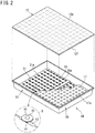
- FIG. 2 is a perspective view showing one example of a configuration of the module 1M.
- the module 1M includes: a housing 11 made of metal and having a rectangular flat-bottomed container shape; and a concentrating portion 12 mounted, like a cover, to the housing 11, for example.
- the concentrating portion 12 is formed by attaching resin condenser lenses 12f to the back face of a single transparent glass plate 12a, for example.
- each of square (10 ⁇ 14) sections shown in FIG. 2 is a Fresnel lens serving as a condenser lens 12f, and can cause sunlight to be converged at the focal point.
- the housing 11 includes a frame body 30 formed from resin, and a bottom plate 31 closing a bottom-side opening 30a of the frame body.
- the frame body 30 is formed in a rectangular cylindrical shape by use of a resin material such as PBT (Poly Butylene Terephtalate) resin loaded with glass fibers, for example.
- a resin material such as PBT (Poly Butylene Terephtalate) resin loaded with glass fibers, for example.
- the bottom plate 31 is a plate-shaped member formed from an aluminum alloy, for example.
- a flexible printed circuit 13 is disposed on an inner surface 31a of the bottom plate 31.
- Cell packages 14 each holding a cell (power generating element) are mounted at predetermined positions on the flexible printed circuit 13.
- the portion surrounded by a "o" (circle) depicted by a chain double-dashed line is an enlarged figure of a light receiving portion R.
- a secondary lens 15 is provided on the cell package 14, and a protection plate 16 is provided around the secondary lens.
- the secondary lens 15 is a ball lens, for example.
- the protection plate 16 is an annular shaped metal body, for example, and a commercially available washer can be used. When converged sunlight deviates from the secondary lens 15, the protection plate 16 prevents the converged light from causing thermal damage to the periphery of the cell. Even when all the converged light enters the secondary lens 15, the protection plate 16 receives scattered light in the housing 11 and reflects the scattered light.
- the light receiving portions R are provided so as to respectively correspond to the condenser lenses 12f by the same number and at the same interval. Therefore, sunlight is concentrated on each light receiving portion R by the condenser lens 12f.
- a shielding plate 17 is provided between the light receiving portion R and the concentrating portion 12.
- openings 17a each corresponding to one condenser lens 12f are formed. Sunlight converged by the condenser lens 12f passes through the opening 17a.
- the incident direction of sunlight is greatly deviated from the optical axis of the light receiving portion R, the light that will be concentrated to a deviated position hits the shielding plate 17.
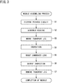
- FIG. 3 shows one example of a process of assembling the aforementioned photovoltaic module 1M.
- the flexible printed circuit 13 is disposed on the inner surface 31a of the bottom plate 31 (step S1).
- step S2 the housing 11 is assembled (step S2), and thus obtained housing 11 is mounted and fixed to a transport jig (step S3).
- FIG. 4 is an exploded perspective view showing the frame body 30, the bottom plate 31, and the transport jig 35.
- the frame body 30 is shown upside down such that an outer surface 31b of the bottom plate 31 faces upward with respect to the surface of the sheet.
- the peripheral edge of the inner surface 31a of the bottom plate 31 is brought into contact with a bottom end surface 30b of the frame body 30, thereby fixing the bottom plate 31 to the frame body 30.
- a caulking agent as an adhesive agent is applied to the peripheral edge of the inner surface 31a of the bottom plate 31 and to the bottom end surface 30b, and thereafter, the peripheral edge of the inner surface 31a of the bottom plate 31 is brought into contact with the bottom end surface 30b.
- the caulking agent is cured around and between the bottom plate 31 and the frame body 30, and a caulking layer adhering them to each other is formed.
- the bottom plate 31 and the frame body 30 are adhered and fixed to each other with this caulking layer.
- a projection 30c is formed on the bottom end surface 30b of the frame body 30, and a cutout portion 31c is formed at a position, in the bottom plate 31, corresponding to the projection 30c.
- the projection 30c and the cutout portion 31c perform positioning between the frame body 30 and the bottom plate 31.
- the projection 30c and the cutout portion 31c are formed in left-right asymmetry so as to be fitted only when the direction of the frame body 30 and the direction of the bottom plate 31 are in the correct relationship.
- the projection 30c and the cutout portion 31c guide the frame body 30 and the bottom plate 31 so as to be combined in correct directions.
- step S3 The housing 11 obtained in step S2 is mounted and fixed to the transport jig 35 for transporting the housing 11 in a horizontally laid state (step S3).
- FIG. 5 is a perspective view showing the transport jig 35.
- the housing 11 is mounted in the horizontally laid state on the upper side of the transport jig 35, and the transport jig 35 transports the housing 11.
- the transport jig 35 includes a rectangular frame 36 (body part), a support portion 37 provided on an upper surface 36a of the frame 36, and a plurality of ball rollers 38 provided on a lower surface 36b of the frame 36.
- the frame 36 is formed in a frame shape by, for example, assembling bar members, each having a C-shaped cross section and formed from an aluminum alloy, in a rectangular shape.
- a short side dimension of the frame 36 is a little larger than a short side dimension of the frame body 30, and a long side dimension of the frame 36 is a little smaller than a long side dimension of the frame body 30.
- the frame 36 is further provided with a handle 35a for handling the transport jig 35 to which the housing 11 is fixed.
- the support portion 37 is provided over almost the entire periphery of the frame 36, and supports the housing 11 from below.
- the support portion 37 includes a bracket 40 fixed to the upper surface 36a of the frame 36, and a pad 41 that is fixed to the upper surface of the bracket 40 and is in contact with the bottom plate 31 of the housing 11.
- the bracket 40 is a plate-shaped member formed from an aluminum alloy. A part, of the bracket 40, formed on each short side of the frame 36 extends along the short side and protrudes outward with respect to the outer surface of the frame 36. A part, of the bracket 40, formed on each long side of the frame 36 extends along the long side and protrudes inward with respect to the inner surface of the frame 36.
- the pad 41 is a member formed from resin, and is fixed to the upper surface of an end portion of the bracket 40. Therefore, a part, of the pad 41, formed on each short side of the frame 36 is disposed outward with respect to the outer surface of the frame 36. Meanwhile, a part, of the pad 41, formed on each long side of the frame 36 is disposed inward with respect to the inner surface of the frame 36.
- the housing 11 is fixed to the transport jig 35 with the bottom plate 31 of the housing 11 being in contact with the upper surface of the pad 41.
- the bottom plate 31 is prevented from being damaged by the pad 41 when the pad 41 comes into contact with the bottom plate 31.
- the plurality of ball rollers 38 come into contact with the floor surface and allow the transport jig 35 to travel freely. This facilitates transportation of the housing 11 fixed to the transport jig 35.
- step S3 first, the pad 41 of the support portion 37 is brought into contact with the bottom plate 31 of the housing 11.
- the pad 41 of the support portion 37 is provided so as to correspond to the bottom end surface 30b of the frame body 30. That is, the pad 41 is formed along almost the entire periphery of the bottom end surface 30b of the frame body 30.
- FIG. 6 shows a state in which the pad 41 of the support portion 37 is in contact with the bottom plate 31 of the housing 11.
- a pair of combiner boxes 45 and output cables 46 extending from the respective combiner boxes 45 are provided on the outer surface 31b of the bottom plate 31.
- the output cables 46 are cables (output codes) for extracting power outputted from the plurality of cells disposed on the inner surface 31a.
- a part, of the support portion 37, provided on each short side of the frame 36 has gaps 47 for releasing the output cables 46 to the outside of the support portion 37.
- output inspection for the photovoltaic module 1M can be performed with the housing 11 being fixed to the transport jig 35.
- fixing members 50 are mounted to fix the housing 11 to the transport jig 35.
- Each fixing member 50 is a tapping screw, for example.
- Two fixing members 50 are mounted to the part, of the support portion 37, on each short side of the frame 36.
- FIG. 7 is a partial cross-sectional view of the transport jig 35 to which the fixing member 50 is fixed, showing a part where the fixing member 50 is mounted.
- a hole 30d into which the fixing member 50 is screwed is formed at the bottom end surface 30b of the frame body 30.
- the frame body 30 is made from resin, if a hole having a diameter that allows the fixing member 50 to be screwed therein is formed, the fixing member 50 can be screwed into the hole.
- the support portion 37 and the bottom plate 31 have a through-hole 37a and a through-hole 31d, respectively, at a position corresponding to the hole 30d of the frame body 30.
- the fixing member 50 is inserted into the through-hole 37a of the support portion 37 and the through-hole 31d of the bottom plate 31 and is screwed and fastened into the hole 30d formed at the bottom end surface 30b of the frame body 30.
- the fixing member 50 being screwed into the hole 30d allows relative positioning between the housing 11 and the transport jig 35.
- the support portion 37 and the bottom plate 31 are held between a head 50a of the fixing member 50 and the bottom end surface 30b of the frame body 30.
- the fixing member 50 presses the pad 41 of the support portion 37 toward the peripheral edge of the outer surface 31b of the bottom plate 31.
- the fixing member 50 fixes the housing 11 to the transport jig 35 while the support portion 37 and the bottom plate 31 are held between the fixing member 50 and the bottom end surface 30b of the frame body 30.
- the fixing member 50 presses the pad 41 toward the peripheral edge of the outer surface 31b of the bottom plate 31 while preventing the bottom plate 31 and the frame body 30 from being relatively displaced, whereby the peripheral edge of the inner surface 31a of the bottom plate 31 can be closely adhered to the bottom end surface 30b of the frame body 30.
- the bottom plate 31 and the frame body 30 can be appropriately adhered to each other.
- the fixing member 50 prevents relative displacement between the bottom plate 31 and the frame body 30, even when adhesion between the bottom plate 31 and the frame body 30 is not completely finished because the caulking agent between the bottom plate 31 and the frame body 30 is not yet dried, the housing 11 can be transported to be advanced to the next work process.
- the fixing member 50 is a tapping screw, and the frame body 30 is made from resin. Therefore, if the hole 30d is formed in the frame body 30, the fixing member 50 can be screwed into the hole 30d.
- the housing 11 can be easily fixed to the transport jig 35 without the necessity of, for example, embedding a nut or the like in the frame body 30 or forming a screw in the frame body 30.
- the fixing member 50 can be screwed into the hole 30d from the outside of the housing 11, fixing and removal of the housing 11 with respect to the transport jig 35 are facilitated.
- the transport jig 35 and the fixing member 50 removed from the housing 11 are reusable.
- step S3 the housing 11 fixed to the transport jig 35 in step S3 is transported to the next step.
- step S4 The housing 11 fixed to the transport jig 35 proceeds to the next step, i.e., an inspective step (step S4).
- an inspective step withstand voltage inspection for the plurality of cells and the like disposed on the inner surface 31a, airtightness inspection between the bottom plate 31 and the frame body 30, and the like are performed (step S4).
- the housing 11 fixed to the transport jig 35 proceeds to a step of mounting the concentrating portion 12 ( FIG. 2 ).
- the concentrating portion 12 is mounted to the housing 11 (step S5).
- the photovoltaic module 1M is obtained.
- step S6 an output inspection regarding the photovoltaic module 1M is performed.
- the housing 11 fixed to the transport jig 35 proceeds to a transport jig removal step, where the housing 11 is removed from the transport jig 35 (step S7).
- the photovoltaic module 1M is completed.
- the housing 11 is fixed to the transport jig 35 while the support portion 37 provided so as to correspond to the bottom end surface 30b of the frame body 30 is in contact with the peripheral edge of the outer surface 31b of the bottom plate 31, the housing 11 can be supported (reinforced) by the transport jig 35 so as to prevent deflection of the resin frame body 30. Therefore, when the housing 11 fixed to the transport jig 35 is subjected to the subsequent work process, it is possible to suppress deflection that occurs in the housing 11 during assembling and transportation between process steps.
- the transport jig 35 of the present embodiment is provided with the handle 35a for handling the transport jig 35, the transport jig 35 can be moved without directly touching the bottom plate 31 and the frame body 30 adhered to each other.
- the transport jig 35 of the present embodiment is provided with the ball rollers 38 in contact with the floor surface, the transport jig 35 can be freely traveled.
- the transport jig 35 capable of traveling with the ball rollers 38 allows the frame 36 to be formed not by a bar member but by a plate member, whereby the degree of freedom in designing the transport jig 35 can be increased.
- FIG. 8 is an exploded perspective view showing the frame body 30, the bottom plate 31, and the transport jig 35.
- the transport jig 35 is based on another embodiment of the present disclosure.
- the transport jig 35 of this embodiment is provided with a holding member 60 for holding the bottom plate 31 so as not to deflect toward the transport jig 35.
- the holding member 60 includes: an elongated holding plate 61 that crosses the inside of the rectangular frame 36 and connects the long sides of the frame 36; and protection pads 62 disposed between the holding plate 61 and the bottom plate 31.
- the bottom plate 31 is held by the holding member 60 so as not to deflect downward. This improves workability when the bottom plate 31 is subjected to the respective steps in the work process.
- the bottom plate 31 can be held more reliably between the column member 30e and the holding member 60.
- clips 65 code holders for holding the output cables 46 on the outer surface 31b are disposed on the outer surface 31b of the bottom plate 31.
- FIG. 9 is an enlarged perspective view of the clip 65. As shown in FIG. 8 and FIG. 9 , the clip 65 is disposed at a position corresponding to the gap 47, and holds the output cable 46 so that a connector 46a at the tip of the output cable 46 is exposed to the outside.
- the connector 46a can be positioned with respect to the bottom plate 31 (housing 11).
- the housing 11 can be fixed to the transport jig 35.
- the housing 11 is easily fixed to the transport jig 35 with the connector 46a of each output cable 46 being released to the outside through the gap 47.
- the connector 46a is positioned with respect to the housing 11, and therefore can be easily connected to an inspection device for the output inspection.
- any means that can hold the output cable 46 such as a band that is fixed to the outer surface 31b and holds the output cable 46 in a removable manner, may be used.
- the hole 30d is formed in the short-side portion of the frame body 30 at the bottom end surface 30b, and the short-side portion of the bottom end surface 30b is fixed to the transport jig 35 by use of the fixing member 50.
- the hole 30d may be formed in the long-side portion of the frame body 30, and the long-side portion of the bottom end surface 30b may be fixed to the transport jig 35 by use of the fixing member 50.
- a tapping screw is used as the fixing member 50.
- the present disclosure is not limited thereto.
- a general bolt can also be used as the fixing member 50 by embedding a nut in the frame body 30 or forming a screw in the frame body 30.
- using the tapping screw as in the present embodiment facilitates fixing of the housing 11 to the transport jig 35.
Landscapes
- Life Sciences & Earth Sciences (AREA)
- Sustainable Development (AREA)
- Photovoltaic Devices (AREA)
Abstract
Description
- The present invention relates to a method for manufacturing a concentrator photovoltaic module, and a transport jig.
- This application claims priority on Japanese Patent Application No.
2018-038644 filed on March 5, 2018 - A unit serving as an optical base unit in a concentrator photovoltaic apparatus includes: for example, a primary condenser lens being a convex lens, a secondary condenser lens being a spherical lens, and a power generating element (see PATENT LITERATURE 1 (
FIG. 8 ), for example). As the power generating element, a solar cell formed by a compound semiconductor element having high power generation efficiency is used. Sunlight is concentrated by the primary condenser lens to be incident on the secondary condenser lens, and then, is further concentrated by the secondary condenser lens to reach the power generating element. - A large number of such concentrator photovoltaic units are arranged in a matrix to form a concentrator photovoltaic module, and then, a large number of such modules are arranged in a matrix to form a concentrator photovoltaic panel. The concentrator photovoltaic panel forms a concentrator photovoltaic apparatus, together with a driving device for causing the panel to perform tracking operation while facing the sun.
- In the concentrator photovoltaic module mentioned above, a bottom plate of a housing has a large number of power generating elements mounted at the surface thereof. As a material of this bottom plate, a metal plate (e.g., an aluminum plate or the like) having a small plate thickness is sometimes used from the viewpoint of suppressing production cost and ensuring heat dissipation performance. A frame body forming an outer frame of the housing supports an outer edge portion of the bottom plate. As a material of this frame body, a resin material is sometimes used to suppress production cost.
- PATENT LITERATURE 1: US Patent Application Publication No.
US2010/0236603A1 -
- (1) A method according to one embodiment is a method for manufacturing a concentrator photovoltaic module including: a plurality of power generating elements onto which sunlight is concentrated by a plurality of condenser lenses; and a housing configured to accommodate the plurality of power generating elements. The housing includes a resin frame body, and a metal bottom plate that closes a bottom-side opening of the frame body and has an inner surface on which the plurality of power generating elements are disposed. The method includes: a first step of bringing a peripheral edge of the inner surface of the bottom plate into contact with a bottom end surface of the frame body, and fixing the bottom plate to the frame body to obtain the housing; and a second step of fixing the housing to a transport jig configured to transport the housing in a horizontally laid state. The transport jig includes a support portion that is provided so as to correspond to the bottom end surface of the frame body, and supports the housing from below. In the second step, the housing is fixed to the transport jig, with the support portion being in contact with a peripheral edge of an outer surface of the bottom plate.
- A transport jig according to another embodiment is a transport jig configured to transport a housing for a photovoltaic module, and the housing accommodates a plurality of power generating elements onto which sunlight is concentrated by a plurality of condenser lenses. The housing includes a resin frame body, and a metal bottom plate that closes a bottom-side opening of the frame body and has an inner surface on which the plurality of power generating elements are disposed. The bottom plate is fixed to the frame body, with a peripheral edge of the inner surface of the bottom plate being in contact with the bottom end surface of the frame body. The transport jig includes a support portion that is provided so as to correspond to the bottom end surface of the frame body and supports the housing from below while being in contact with an peripheral edge of an outer surface of the bottom plate. The transport jig transports the housing in a horizontally laid state.
-
-
FIG. 1 is a perspective view showing one example of a concentrator photovoltaic apparatus. -
FIG. 2 is a perspective view showing one example of a module configuration. -
FIG. 3 shows a process of assembling a photovoltaic module. -
FIG. 4 is an exploded perspective view showing a frame body, a bottom plate, and atransport jig 35. -
FIG. 5 is a perspective view showing the transport jig. -
FIG. 6 shows a state in which a pad of a support portion is in contact with a bottom plate of a housing. -
FIG. 7 is a partial cross-sectional view of the transport jig to which a fixing member is fixed. -
FIG. 8 is an exploded perspective view showing aframe body 30, abottom plate 31, and atransport jig 35 according to another embodiment. -
FIG. 9 is an enlarged perspective view of aclip 65. - In a case where the frame body forming the housing of the concentrator photovoltaic module is formed from a resin material, rigidity of the housing is relatively low because of the resin frame body, which may cause deflection of the housing during assembling of the concentrator photovoltaic module or transportation between process steps.
- Such deflection of the housing during assembling or transportation adversely affects a product tolerance and/or performance as a module, and therefore, is desired to be suppressed as much as possible.
- The present disclosure has been made in view of the above circumstances, and an object of the present disclosure is to provide a technology for suppressing deflection of a housing during assembling or transportation.
- According to the present disclosure, deflection that occurs in a housing during assembling or transportation can be suppressed.
- First, contents of embodiments of the present disclosure are listed and described.
-
- (1) A method according to one embodiment is a method for manufacturing a concentrator photovoltaic module including: a plurality of power generating elements onto which sunlight is concentrated by a plurality of condenser lenses; and a housing configured to accommodate the plurality of power generating elements. The housing includes a resin frame body, and a metal bottom plate that closes a bottom-side opening of the frame body and has an inner surface on which the plurality of power generating elements are disposed. The method includes: a first step of bringing a peripheral edge of the inner surface of the bottom plate into contact with a bottom end surface of the frame body, and fixing the bottom plate to the frame body to obtain the housing; and a second step of fixing the housing to a transport jig configured to transport the housing in a horizontally laid state. The transport jig includes a support portion that is provided so as to correspond to the bottom end surface of the frame body, and supports the housing from below. In the second step, the housing is fixed to the transport jig, with the support portion being in contact with a peripheral edge of an outer surface of the bottom plate.
According to the method for manufacturing the photovoltaic module of the above configuration, since the housing is fixed to the transport jig while the support portion provided so as to correspond to the bottom end surface of the frame body is in contact with the peripheral edge of the outer surface of the bottom plate, the housing can be supported by the transport jig without deflection of the resin frame body. Therefore, when the housing fixed to the transport jig is subjected to the subsequent work process, it is possible to suppress deflection that occurs in the housing during assembling and transportation between process steps. - (2) In the above method for manufacturing the photovoltaic module, in the first step, preferably, the bottom plate is adhesively fixed to the frame body. In the second step, preferably, the housing is fixed to the transport jig by means of a fixing member such that the support portion and the bottom plate are held between the fixing member and the bottom end surface of the frame body.
In this case, the fixing member presses the support portion toward the bottom plate while preventing the bottom plate and the frame body from being relatively displaced, whereby the bottom plate and the frame body can be closely adhered to each other. As a result, the bottom plate and the frame body can be appropriately adhered to each other, and the housing fixed to the transport jig can be transported to the next work process with the bottom plate and the frame body being adhered to each other. - (3) In the above method for manufacturing the concentrator photovoltaic module, preferably, the fixing member is a tapping screw that penetrates through the support portion and the bottom plate and is screwed into a hole formed at the bottom end surface of the frame body.
In this case, since the frame body is formed from resin, if a hole is formed in the frame body, the fixing member can be screwed into the hole, whereby the housing can be easily fixed to the transport jig.
Since the fixing member can be screwed into the hole from the outside of the housing, fixing and removal of the housing to and from the transport jig are facilitated.
The transport jig and the fixing member removed from the housing are reusable. - (4) In the above method for manufacturing the concentrator photovoltaic module, an output code connected to the plurality of power generating elements is provided on the outer surface of the bottom plate. In the second step, the housing may be fixed to the transport jig, with the output code being released to the outside of the support portion through a gap formed in the support portion to release the output code to the outside of the support portion.
In this case, output inspection for the photovoltaic module can be performed with the housing being fixed to the transport jig. - (5) In the above method for manufacturing the concentrator photovoltaic module, on the outer surface of the bottom plate, a code holder for holding the output code is provided so as to correspond to the gap. In the second step, the housing may be fixed to the transport jig, with the output code being released to the outside of the support portion through the gap formed in the support portion to release the output code to the outside of the support portion, and with the output code being held by the code holder while being released to the outside of the support portion.
In this case, the housing can be easily fixed to the transport jig, with the output code being released to the outside of the support portion. - (6) A transport jig according to another embodiment is a transport jig configured to transport a housing for a concentrator photovoltaic module, and the housing accommodates a plurality of power generating elements onto which sunlight is concentrated by a plurality of condenser lenses. The housing includes a resin frame body, and a metal bottom plate that closes a bottom-side opening of the frame body and has an inner surface on which the plurality of power generating elements are disposed. The bottom plate is fixed to the frame body, with a peripheral edge of the inner surface of the bottom plate being in contact with the bottom end surface of the frame body. The transport jig includes a support portion that is provided so as to correspond to the bottom end surface of the frame body and supports the housing from below while being in contact with an peripheral edge of an outer surface of the bottom plate. The transport jig transports the housing in a horizontally laid state.
According to the transport jig of the above configuration, since the housing is transported to the subsequent work process while being fixed to the transport jig, deflection that occurs in the housing during assembling and transportation between process steps can be suppressed. - (7) The above transport jig may further include a handle for handling the transport jig.
In this case, the transport jig can be moved without directly touching the bottom plate and the frame body adhered to each other. - (8) Preferably, the above transport jig further includes ball rollers that are in contact with a floor surface where the transport jig is placed, and allow the transport jig to travel freely.
In this case, transportation of the housing fixed to the transport jig is facilitated. - (9) Preferably, the above transport jig further includes: a rectangular frame-shaped body part on which the support portion is provided; and a bottom plate holding portion that is provided so as to cross the inside of the frame-shaped body part, and holds the bottom plate from below.
- In this case, while the housing is fixed to the transport jig and transported between process steps, the bottom plate is held by the holding member so as not to deflect downward. This improves workability when the bottom plate is subjected to the respective process steps in the work process.
- Hereinafter, preferred embodiments will be described with reference to the drawings.
- At least some parts of the embodiments described below may be combined together as desired.
-
FIG. 1 is a perspective view showing one example of a concentrator photovoltaic apparatus. - In
FIG. 1 , thisphotovoltaic apparatus 100 includes: an array (the entire photovoltaic panel) 1 having a shape that is continuous on the upper side and is divided into left and right portions on the lower side; and asupport device 2 for supporting thearray 1. Thearray 1 is formed by a plurality ofmodules 1M being arrayed. In the example shown inFIG. 1 , thearray 1 is configured as an assembly composed of 200modules 1M in total, i.e., 192 (96 (=12×8)×2) modules forming the left and right wings and 8 modules forming the connection portion at the center. - The
support device 2 includes apost 21, abase 22, a biaxial drive part 23, and ahorizontal shaft 24 serving as a drive shaft. The lower end of thepost 21 is fixed to thebase 22, and the upper end of thepost 21 is provided with the biaxial drive part 23. - In
FIG. 1 , thepost 21 is parallel to the vertical direction, and thehorizontal shaft 24 is parallel to the horizontal direction. The biaxial drive part 23 can rotate thehorizontal shaft 24 in two directions of azimuth (angle around thepost 21 as the center axis) and elevation (angle around thehorizontal shaft 24 as the center axis). -
FIG. 1 shows thesupport device 2 that supports thearray 1 by thesingle post 21. However, the configuration of thesupport device 2 is not limited thereto. That is, any support device that can support thearray 1 so as to be movable in two axes (azimuth, elevation) can be employed. -
FIG. 2 is a perspective view showing one example of a configuration of themodule 1M. InFIG. 2 , in terms of the physical form in appearance, themodule 1M includes: ahousing 11 made of metal and having a rectangular flat-bottomed container shape; and a concentratingportion 12 mounted, like a cover, to thehousing 11, for example. The concentratingportion 12 is formed by attachingresin condenser lenses 12f to the back face of a singletransparent glass plate 12a, for example. For example, each of square (10×14) sections shown inFIG. 2 is a Fresnel lens serving as acondenser lens 12f, and can cause sunlight to be converged at the focal point. - The
housing 11 includes aframe body 30 formed from resin, and abottom plate 31 closing a bottom-side opening 30a of the frame body. - The
frame body 30 is formed in a rectangular cylindrical shape by use of a resin material such as PBT (Poly Butylene Terephtalate) resin loaded with glass fibers, for example. - The
bottom plate 31 is a plate-shaped member formed from an aluminum alloy, for example. - A flexible printed
circuit 13 is disposed on aninner surface 31a of thebottom plate 31. Cell packages 14 each holding a cell (power generating element) are mounted at predetermined positions on the flexible printedcircuit 13. - In
FIG. 2 , the portion surrounded by a "o" (circle) depicted by a chain double-dashed line is an enlarged figure of a light receiving portion R. In the light receiving portion R, asecondary lens 15 is provided on thecell package 14, and aprotection plate 16 is provided around the secondary lens. Thesecondary lens 15 is a ball lens, for example. Theprotection plate 16 is an annular shaped metal body, for example, and a commercially available washer can be used. When converged sunlight deviates from thesecondary lens 15, theprotection plate 16 prevents the converged light from causing thermal damage to the periphery of the cell. Even when all the converged light enters thesecondary lens 15, theprotection plate 16 receives scattered light in thehousing 11 and reflects the scattered light. - The light receiving portions R are provided so as to respectively correspond to the
condenser lenses 12f by the same number and at the same interval. Therefore, sunlight is concentrated on each light receiving portion R by thecondenser lens 12f. - A shielding
plate 17 is provided between the light receiving portion R and the concentratingportion 12. In the shieldingplate 17, at positions corresponding to theindividual condenser lenses 12f,openings 17a each corresponding to onecondenser lens 12f are formed. Sunlight converged by thecondenser lens 12f passes through theopening 17a. When the incident direction of sunlight is greatly deviated from the optical axis of the light receiving portion R, the light that will be concentrated to a deviated position hits the shieldingplate 17. -
FIG. 3 shows one example of a process of assembling the aforementionedphotovoltaic module 1M. - In order to assemble the
photovoltaic module 1M, first, the flexible printedcircuit 13 is disposed on theinner surface 31a of the bottom plate 31 (step S1). - Next, the
housing 11 is assembled (step S2), and thus obtainedhousing 11 is mounted and fixed to a transport jig (step S3). -
FIG. 4 is an exploded perspective view showing theframe body 30, thebottom plate 31, and thetransport jig 35. InFIG. 4 , theframe body 30 is shown upside down such that anouter surface 31b of thebottom plate 31 faces upward with respect to the surface of the sheet. - In assembling the
housing 11 in step S2, the peripheral edge of theinner surface 31a of thebottom plate 31 is brought into contact with abottom end surface 30b of theframe body 30, thereby fixing thebottom plate 31 to theframe body 30. At this time, a caulking agent as an adhesive agent is applied to the peripheral edge of theinner surface 31a of thebottom plate 31 and to thebottom end surface 30b, and thereafter, the peripheral edge of theinner surface 31a of thebottom plate 31 is brought into contact with thebottom end surface 30b. Thus, the caulking agent is cured around and between thebottom plate 31 and theframe body 30, and a caulking layer adhering them to each other is formed. Thebottom plate 31 and theframe body 30 are adhered and fixed to each other with this caulking layer. - A
projection 30c is formed on thebottom end surface 30b of theframe body 30, and acutout portion 31c is formed at a position, in thebottom plate 31, corresponding to theprojection 30c. Theprojection 30c and thecutout portion 31c perform positioning between theframe body 30 and thebottom plate 31. Theprojection 30c and thecutout portion 31c are formed in left-right asymmetry so as to be fitted only when the direction of theframe body 30 and the direction of thebottom plate 31 are in the correct relationship. Thus, theprojection 30c and thecutout portion 31c guide theframe body 30 and thebottom plate 31 so as to be combined in correct directions. Although only oneprojection 30c and onecutout portion 31c are shown inFIG. 4 , a plurality ofprojections 30c andcorresponding cutout portions 31c are provided. - The
housing 11 obtained in step S2 is mounted and fixed to thetransport jig 35 for transporting thehousing 11 in a horizontally laid state (step S3). -
FIG. 5 is a perspective view showing thetransport jig 35. With reference toFIG. 5 andFIG. 4 , thehousing 11 is mounted in the horizontally laid state on the upper side of thetransport jig 35, and thetransport jig 35 transports thehousing 11. - The
transport jig 35 includes a rectangular frame 36 (body part), asupport portion 37 provided on anupper surface 36a of theframe 36, and a plurality ofball rollers 38 provided on alower surface 36b of theframe 36. - The
frame 36 is formed in a frame shape by, for example, assembling bar members, each having a C-shaped cross section and formed from an aluminum alloy, in a rectangular shape. A short side dimension of theframe 36 is a little larger than a short side dimension of theframe body 30, and a long side dimension of theframe 36 is a little smaller than a long side dimension of theframe body 30. - The
frame 36 is further provided with ahandle 35a for handling thetransport jig 35 to which thehousing 11 is fixed. - The
support portion 37 is provided over almost the entire periphery of theframe 36, and supports thehousing 11 from below. Thesupport portion 37 includes abracket 40 fixed to theupper surface 36a of theframe 36, and apad 41 that is fixed to the upper surface of thebracket 40 and is in contact with thebottom plate 31 of thehousing 11. - The
bracket 40 is a plate-shaped member formed from an aluminum alloy. A part, of thebracket 40, formed on each short side of theframe 36 extends along the short side and protrudes outward with respect to the outer surface of theframe 36. A part, of thebracket 40, formed on each long side of theframe 36 extends along the long side and protrudes inward with respect to the inner surface of theframe 36. - The
pad 41 is a member formed from resin, and is fixed to the upper surface of an end portion of thebracket 40. Therefore, a part, of thepad 41, formed on each short side of theframe 36 is disposed outward with respect to the outer surface of theframe 36. Meanwhile, a part, of thepad 41, formed on each long side of theframe 36 is disposed inward with respect to the inner surface of theframe 36. - The
housing 11 is fixed to thetransport jig 35 with thebottom plate 31 of thehousing 11 being in contact with the upper surface of thepad 41. - Since the
pad 41 is formed from resin, thebottom plate 31 is prevented from being damaged by thepad 41 when thepad 41 comes into contact with thebottom plate 31. - When the
transport jig 35 is placed on a floor surface, the plurality ofball rollers 38 come into contact with the floor surface and allow thetransport jig 35 to travel freely. This facilitates transportation of thehousing 11 fixed to thetransport jig 35. - In step S3, first, the
pad 41 of thesupport portion 37 is brought into contact with thebottom plate 31 of thehousing 11. - The
pad 41 of thesupport portion 37 is provided so as to correspond to thebottom end surface 30b of theframe body 30. That is, thepad 41 is formed along almost the entire periphery of thebottom end surface 30b of theframe body 30. - Therefore, when the
pad 41 of thesupport portion 37 is brought into contact with thebottom plate 31 of thehousing 11, thepad 41 comes into contact with almost the entire periphery of the edge of theouter surface 31b of thebottom plate 31. -
FIG. 6 shows a state in which thepad 41 of thesupport portion 37 is in contact with thebottom plate 31 of thehousing 11. - A pair of
combiner boxes 45 andoutput cables 46 extending from therespective combiner boxes 45 are provided on theouter surface 31b of thebottom plate 31. Theoutput cables 46 are cables (output codes) for extracting power outputted from the plurality of cells disposed on theinner surface 31a. - A part, of the
support portion 37, provided on each short side of theframe 36 hasgaps 47 for releasing theoutput cables 46 to the outside of thesupport portion 37. - Therefore, when the
pad 41 of thesupport portion 37 is brought into contact with thebottom plate 31 of thehousing 11, the tips of theoutput cables 46 are released to the outside through thegaps 47. - Thus, in the subsequent work process, output inspection for the
photovoltaic module 1M can be performed with thehousing 11 being fixed to thetransport jig 35. - Next, fixing
members 50 are mounted to fix thehousing 11 to thetransport jig 35. - Each fixing
member 50 is a tapping screw, for example. Two fixingmembers 50 are mounted to the part, of thesupport portion 37, on each short side of theframe 36. -
FIG. 7 is a partial cross-sectional view of thetransport jig 35 to which the fixingmember 50 is fixed, showing a part where the fixingmember 50 is mounted. - As shown in
FIG. 7 , ahole 30d into which the fixingmember 50 is screwed is formed at thebottom end surface 30b of theframe body 30. In the present embodiment, since theframe body 30 is made from resin, if a hole having a diameter that allows the fixingmember 50 to be screwed therein is formed, the fixingmember 50 can be screwed into the hole. - The
support portion 37 and thebottom plate 31 have a through-hole 37a and a through-hole 31d, respectively, at a position corresponding to thehole 30d of theframe body 30. - The fixing
member 50 is inserted into the through-hole 37a of thesupport portion 37 and the through-hole 31d of thebottom plate 31 and is screwed and fastened into thehole 30d formed at thebottom end surface 30b of theframe body 30. - The fixing
member 50 being screwed into thehole 30d allows relative positioning between thehousing 11 and thetransport jig 35. - Since the fixing
member 50 is screwed and fastened into thehole 30d, thesupport portion 37 and thebottom plate 31 are held between ahead 50a of the fixingmember 50 and thebottom end surface 30b of theframe body 30. - Thus, the fixing
member 50 presses thepad 41 of thesupport portion 37 toward the peripheral edge of theouter surface 31b of thebottom plate 31. - In this way, the fixing
member 50 fixes thehousing 11 to thetransport jig 35 while thesupport portion 37 and thebottom plate 31 are held between the fixingmember 50 and thebottom end surface 30b of theframe body 30. - In this case, the fixing
member 50 presses thepad 41 toward the peripheral edge of theouter surface 31b of thebottom plate 31 while preventing thebottom plate 31 and theframe body 30 from being relatively displaced, whereby the peripheral edge of theinner surface 31a of thebottom plate 31 can be closely adhered to thebottom end surface 30b of theframe body 30. As a result, thebottom plate 31 and theframe body 30 can be appropriately adhered to each other. - Since the fixing
member 50 prevents relative displacement between thebottom plate 31 and theframe body 30, even when adhesion between thebottom plate 31 and theframe body 30 is not completely finished because the caulking agent between thebottom plate 31 and theframe body 30 is not yet dried, thehousing 11 can be transported to be advanced to the next work process. - In the present embodiment, the fixing
member 50 is a tapping screw, and theframe body 30 is made from resin. Therefore, if thehole 30d is formed in theframe body 30, the fixingmember 50 can be screwed into thehole 30d. Thus, thehousing 11 can be easily fixed to thetransport jig 35 without the necessity of, for example, embedding a nut or the like in theframe body 30 or forming a screw in theframe body 30. - Since the fixing
member 50 can be screwed into thehole 30d from the outside of thehousing 11, fixing and removal of thehousing 11 with respect to thetransport jig 35 are facilitated. - The
transport jig 35 and the fixingmember 50 removed from thehousing 11 are reusable. - Referring back to
FIG. 3 , thehousing 11 fixed to thetransport jig 35 in step S3 is transported to the next step. - The
housing 11 fixed to thetransport jig 35 proceeds to the next step, i.e., an inspective step (step S4). In the inspection step, withstand voltage inspection for the plurality of cells and the like disposed on theinner surface 31a, airtightness inspection between thebottom plate 31 and theframe body 30, and the like are performed (step S4). - Thereafter, the
housing 11 fixed to thetransport jig 35 proceeds to a step of mounting the concentrating portion 12 (FIG. 2 ). In the step of mounting the concentratingportion 12, the concentratingportion 12 is mounted to the housing 11 (step S5). Thus, thephotovoltaic module 1M is obtained. - Then, the
housing 11 fixed to thetransport jig 35 proceeds to an output inspection step (step S6), where an output inspection regarding thephotovoltaic module 1M is performed. - Thereafter, the
housing 11 fixed to thetransport jig 35 proceeds to a transport jig removal step, where thehousing 11 is removed from the transport jig 35 (step S7). - Thus, the
photovoltaic module 1M is completed. - As described above, according to the assembling process (manufacturing method) for the
photovoltaic module 1M of the present embodiment, since thehousing 11 is fixed to thetransport jig 35 while thesupport portion 37 provided so as to correspond to thebottom end surface 30b of theframe body 30 is in contact with the peripheral edge of theouter surface 31b of thebottom plate 31, thehousing 11 can be supported (reinforced) by thetransport jig 35 so as to prevent deflection of theresin frame body 30. Therefore, when thehousing 11 fixed to thetransport jig 35 is subjected to the subsequent work process, it is possible to suppress deflection that occurs in thehousing 11 during assembling and transportation between process steps. - Since the
transport jig 35 of the present embodiment is provided with thehandle 35a for handling thetransport jig 35, thetransport jig 35 can be moved without directly touching thebottom plate 31 and theframe body 30 adhered to each other. - Since the
transport jig 35 of the present embodiment is provided with theball rollers 38 in contact with the floor surface, thetransport jig 35 can be freely traveled. Thetransport jig 35 capable of traveling with theball rollers 38 allows theframe 36 to be formed not by a bar member but by a plate member, whereby the degree of freedom in designing thetransport jig 35 can be increased. -
FIG. 8 is an exploded perspective view showing theframe body 30, thebottom plate 31, and thetransport jig 35. Thetransport jig 35 is based on another embodiment of the present disclosure. - The
transport jig 35 of this embodiment is provided with a holdingmember 60 for holding thebottom plate 31 so as not to deflect toward thetransport jig 35. - The holding
member 60 includes: anelongated holding plate 61 that crosses the inside of therectangular frame 36 and connects the long sides of theframe 36; andprotection pads 62 disposed between the holdingplate 61 and thebottom plate 31. - While the
housing 11 is fixed to thetransport jig 35 and transported between process steps, thebottom plate 31 is held by the holdingmember 60 so as not to deflect downward. This improves workability when thebottom plate 31 is subjected to the respective steps in the work process. - If a
column member 30e is disposed so as to cross the bottom-side opening 30a of theframe body 30, thebottom plate 31 can be held more reliably between thecolumn member 30e and the holdingmember 60. - Furthermore, tips of
output cables 46 are released to the outside throughgaps 47. In this embodiment, clips 65 (code holders) for holding theoutput cables 46 on theouter surface 31b are disposed on theouter surface 31b of thebottom plate 31. -
FIG. 9 is an enlarged perspective view of theclip 65. As shown inFIG. 8 andFIG. 9 , theclip 65 is disposed at a position corresponding to thegap 47, and holds theoutput cable 46 so that aconnector 46a at the tip of theoutput cable 46 is exposed to the outside. - Thus, the
connector 46a can be positioned with respect to the bottom plate 31 (housing 11). - Therefore, when the
pad 41 of thesupport portion 37 is brought into contact with thebottom plate 31 of thehousing 11, theconnector 46a of eachoutput cable 46 is released to the outside through thegap 47, and theoutput cable 46 is held by theclip 65 with theconnector 46a being released to the outside through thegap 47. Thus, thehousing 11 can be fixed to thetransport jig 35. - Thus, the
housing 11 is easily fixed to thetransport jig 35 with theconnector 46a of eachoutput cable 46 being released to the outside through thegap 47. - Furthermore, when the output inspection is performed with the
housing 11 being fixed to thetransport jig 35, theconnector 46a is positioned with respect to thehousing 11, and therefore can be easily connected to an inspection device for the output inspection. - While a clip is used for holding the
output cable 46 in the present embodiment, any means that can hold theoutput cable 46, such as a band that is fixed to theouter surface 31b and holds theoutput cable 46 in a removable manner, may be used. - It should be noted that the embodiments disclosed herein are merely illustrative and not restrictive in all aspects.
- In the above embodiments, the
hole 30d is formed in the short-side portion of theframe body 30 at thebottom end surface 30b, and the short-side portion of thebottom end surface 30b is fixed to thetransport jig 35 by use of the fixingmember 50. However, thehole 30d may be formed in the long-side portion of theframe body 30, and the long-side portion of thebottom end surface 30b may be fixed to thetransport jig 35 by use of the fixingmember 50. - In the above embodiments, a tapping screw is used as the fixing
member 50. However, the present disclosure is not limited thereto. For example, a general bolt can also be used as the fixingmember 50 by embedding a nut in theframe body 30 or forming a screw in theframe body 30. However, using the tapping screw as in the present embodiment facilitates fixing of thehousing 11 to thetransport jig 35. - The scope of the present disclosure is defined by the scope of the claims rather than by the meaning described above, and is intended to include meaning equivalent to the scope of the claims and all modifications within the scope.
-
- 1
- array
- 1M
- photovoltaic module
- 2
- support device
- 11
- housing
- 12
- concentrating portion
- 12a
- glass plate
- 12f
- condenser lens
- 13
- flexible printed circuit
- 14
- cell package
- 15
- secondary lens
- 16
- protection plate
- 17
- shielding plate
- 17a
- opening
- 21
- post
- 22
- base
- 23
- biaxial drive part
- 24
- horizontal shaft
- 30
- frame body
- 30a
- bottom-side opening
- 30b
- bottom end surface
- 30c
- projection
- 30d
- hole
- 30e
- column member
- 31
- bottom plate
- 31a
- inner surface
- 31b
- outer surface
- 31c
- cutout portion
- 31d
- through-hole
- 35
- transport jig
- 35a
- handle
- 36
- frame
- 36a
- upper surface
- 36b
- lower surface
- 37
- support portion
- 37a
- through-hole
- 38
- ball roller
- 40
- bracket
- 41
- pad
- 45
- combiner box
- 46
- output cable
- 46a
- connector
- 47
- gap
- 50
- fixing member
- 50a
- head
- 60
- holding member
- 61
- holding plate
- 62
- protection pad
- 65
- clip
- 100
- photovoltaic apparatus
- R
- light receiving portion
Claims (9)
- A method for manufacturing a concentrator photovoltaic module including: a plurality of power generating elements onto which sunlight is concentrated by a plurality of condenser lenses; and a housing configured to accommodate the plurality of power generating elements, the housing including a resin frame body, and a metal bottom plate that closes a bottom-side opening of the frame body and has an inner surface on which the plurality of power generating elements are disposed,
the method comprising:a first step of bringing a peripheral edge of the inner surface of the bottom plate into contact with a bottom end surface of the frame body, and fixing the bottom plate to the frame body to obtain the housing; anda second step of fixing the housing to a transport jig configured to transport the housing in a horizontally laid state, whereinthe transport jig includes a support portion that is provided so as to correspond to the bottom end surface of the frame body, and supports the housing from below, andin the second step, the housing is fixed to the transport jig, with the support portion being in contact with a peripheral edge of an outer surface of the bottom plate. - The method for manufacturing the photovoltaic module according to claim 1, wherein
in the first step, the bottom plate is adhesively fixed to the frame body, and
in the second step, the housing is fixed to the transport jig by means of a fixing member such that the support portion and the bottom plate are held between the fixing member and the bottom end surface of the frame body. - The method for manufacturing the concentrator photovoltaic module according to claim 2, wherein the fixing member is a tapping screw that penetrates through the support portion and the bottom plate and is screwed into a hole formed at the bottom end surface of the frame body.
- The method for manufacturing the concentrator photovoltaic module according to any one of claims 1 to 3, wherein
an output code connected to the plurality of power generating elements is provided on the outer surface of the bottom plate, and
in the second step, the housing is fixed to the transport jig, with the output code being released to the outside of the support portion through a gap formed in the support portion to release the output code to the outside of the support portion. - The method for manufacturing the concentrator photovoltaic module according to claim 4, wherein
on the outer surface of the bottom plate, a code holder for holding the output code is provided so as to correspond to the gap, and
in the second step, the output code is released to the outside of the support portion through the gap formed in the support portion to release the output code to the outside of the support portion, the output code is held by the code holder while being released to the outside of the support portion, and the housing is fixed to the transport jig. - A transport jig configured to transport a housing for a concentrator photovoltaic module, the housing accommodating a plurality of power generating elements onto which sunlight is concentrated by a plurality of condenser lenses, wherein
the housing includes a resin frame body, and a metal bottom plate that closes a bottom-side opening of the frame body and has an inner surface on which the plurality of power generating elements are disposed, and the bottom plate is fixed to the frame body, with a peripheral edge of the inner surface of the bottom plate being in contact with the bottom end surface of the frame body,
the transport jig includes a support portion that is provided so as to correspond to the bottom end surface of the frame body and supports the housing from below while being in contact with an peripheral edge of an outer surface of the bottom plate, and
the transport jig transports the housing in a horizontally laid state. - The transport jig according to claim 6 further including a handle for handling the transport jig.
- The transport jig according to claim 6 or 7 further including ball rollers that are in contact with a floor surface where the transport jig is placed, and allow the transport jig to travel freely.
- The transport jig according to any one of claims 6 to 8, further comprising:a rectangular frame-shaped body part on which the support portion is provided; anda bottom plate holding portion that is provided so as to cross the inside of the frame-shaped body part, and holds the bottom plate from below.
Applications Claiming Priority (2)
| Application Number | Priority Date | Filing Date | Title |
|---|---|---|---|
| JP2018038644 | 2018-03-05 | ||
| PCT/JP2019/006479 WO2019171966A1 (en) | 2018-03-05 | 2019-02-21 | Method for manufacturing concentrator photovoltaic module, and carrier jig |
Publications (3)
| Publication Number | Publication Date |
|---|---|
| EP3764539A1 true EP3764539A1 (en) | 2021-01-13 |
| EP3764539A4 EP3764539A4 (en) | 2021-12-29 |
| EP3764539B1 EP3764539B1 (en) | 2022-11-02 |
Family
ID=67847128
Family Applications (1)
| Application Number | Title | Priority Date | Filing Date |
|---|---|---|---|
| EP19763506.3A Active EP3764539B1 (en) | 2018-03-05 | 2019-02-21 | Method for manufacturing concentrator photovoltaic module, and carrier jig |
Country Status (7)
| Country | Link |
|---|---|
| US (1) | US11742454B2 (en) |
| EP (1) | EP3764539B1 (en) |
| JP (1) | JPWO2019171966A1 (en) |
| AU (1) | AU2019230301A1 (en) |
| MA (1) | MA58647B1 (en) |
| TW (1) | TW201944013A (en) |
| WO (1) | WO2019171966A1 (en) |
Families Citing this family (1)
| Publication number | Priority date | Publication date | Assignee | Title |
|---|---|---|---|---|
| CN222532152U (en) * | 2024-05-27 | 2025-02-25 | 宁德时代新能源科技股份有限公司 | Battery production equipment |
Family Cites Families (25)
| Publication number | Priority date | Publication date | Assignee | Title |
|---|---|---|---|---|
| GB2000860B (en) * | 1977-07-06 | 1982-08-04 | Showa Aluminium Co Ltd | Solar collector |
| US5993582A (en) * | 1996-08-13 | 1999-11-30 | Canon Kabushiki Kaisha | Continuous vacuum lamination treatment system and vacuum lamination apparatus |
| EP1071137A3 (en) * | 1999-07-21 | 2007-03-21 | Kaneka Corporation | Roofing tile having photovoltaic module to generate power |
| JP3531599B2 (en) * | 2000-10-27 | 2004-05-31 | セイコーエプソン株式会社 | Work holder for through hole inspection device |
| US20050081909A1 (en) * | 2003-10-20 | 2005-04-21 | Paull James B. | Concentrating solar roofing shingle |
| US8237044B2 (en) * | 2005-06-07 | 2012-08-07 | Sharp Kabushiki Kaisha | Concentrating solar power generation unit, concentrating solar power generation apparatus, concetrating lens, concentrating lens structure, and method of manufacturing concentrating lens structure |
| US20090000662A1 (en) * | 2007-03-11 | 2009-01-01 | Harwood Duncan W J | Photovoltaic receiver for solar concentrator applications |
| EP2312646A1 (en) * | 2008-06-23 | 2011-04-20 | Sharp Kabushiki Kaisha | Solar cell, photoconcentration-type photovoltaic module, and method for manufacturing solar cell |
| JP2010109090A (en) * | 2008-10-29 | 2010-05-13 | Kyocera Corp | Solar battery module support body |
| CN106449805B (en) | 2009-02-09 | 2019-03-12 | 艾克斯瑟乐普林特有限公司 | Concentrator type photovoltaic (CPV) module, receiver and sub-receiver and method of forming the same |
| JP2011051609A (en) | 2009-08-31 | 2011-03-17 | Sekisui Plastics Co Ltd | Solar battery panel conveyance tray and solar battery panel package |
| AT509124A1 (en) * | 2009-11-18 | 2011-06-15 | Hilber Franz | ADJUSTING DEVICE FOR A STATIONARY PHOTOVOLTAIC PLANT |
| US20120037206A1 (en) * | 2010-08-16 | 2012-02-16 | Richard Norman | Systems for cost effective concentration and utilization of solar energy |
| US20130240466A1 (en) * | 2011-11-05 | 2013-09-19 | Gregory W. Sponseller | Photovoltaic panel racking assembly for use in connection with roof installation of panels |
| US9020636B2 (en) * | 2010-12-16 | 2015-04-28 | Saied Tadayon | Robot for solar farms |
| US20140360552A1 (en) * | 2012-07-19 | 2014-12-11 | Brittmore Group LLC | Solar Panel Field Array Support System and Apparatus and Method for Construction Use |
| JP2013084670A (en) * | 2011-10-06 | 2013-05-09 | Sharp Corp | Solar cell module, solar light power generation unit, and manufacturing method of the solar cell module |
| DE202011108836U1 (en) * | 2011-12-08 | 2011-12-29 | Grenzebach Maschinenbau Gmbh | Apparatus for the industrial production of photovoltaic concentrator modules |
| EP2789021B1 (en) | 2011-12-09 | 2018-07-11 | X-Celeprint Limited | High concentration photovoltaic modules and methods of fabricating the same |
| JP2013129444A (en) * | 2011-12-21 | 2013-07-04 | Sharp Corp | Holding structure |
| JP6291870B2 (en) * | 2014-01-30 | 2018-03-14 | 大同特殊鋼株式会社 | Solar power module stack |
| JP6424737B2 (en) * | 2015-05-25 | 2018-11-21 | 住友電気工業株式会社 | Concentrated solar power generation module, concentrated solar power generation panel, and concentrated solar power generation apparatus |
| JP6569340B2 (en) * | 2015-07-09 | 2019-09-04 | 住友電気工業株式会社 | Case mounting structure for concentrating solar power generation module, concentrating solar power generation module, concentrating solar power generation panel, and concentrating solar power generation apparatus |
| JP6631436B2 (en) * | 2016-08-03 | 2020-01-15 | 住友電気工業株式会社 | Concentrating solar power module, concentrating solar power panel, and concentrating solar power generation device |
| JP2018038644A (en) | 2016-09-08 | 2018-03-15 | 株式会社三共 | Game machine |
-
2019
- 2019-02-21 MA MA58647A patent/MA58647B1/en unknown
- 2019-02-21 EP EP19763506.3A patent/EP3764539B1/en active Active
- 2019-02-21 JP JP2020504913A patent/JPWO2019171966A1/en active Pending
- 2019-02-21 US US16/976,928 patent/US11742454B2/en active Active
- 2019-02-21 WO PCT/JP2019/006479 patent/WO2019171966A1/en not_active Ceased
- 2019-02-21 AU AU2019230301A patent/AU2019230301A1/en not_active Abandoned
- 2019-03-04 TW TW108106990A patent/TW201944013A/en unknown
Also Published As
| Publication number | Publication date |
|---|---|
| US11742454B2 (en) | 2023-08-29 |
| MA58647B1 (en) | 2022-12-30 |
| EP3764539A4 (en) | 2021-12-29 |
| JPWO2019171966A1 (en) | 2021-02-18 |
| AU2019230301A1 (en) | 2020-09-24 |
| WO2019171966A1 (en) | 2019-09-12 |
| US20210013364A1 (en) | 2021-01-14 |
| TW201944013A (en) | 2019-11-16 |
| EP3764539B1 (en) | 2022-11-02 |
Similar Documents
| Publication | Publication Date | Title |
|---|---|---|
| CN107852129B (en) | Mounting structure for concentrating photovoltaic module housing, concentrating photovoltaic module, concentrating photovoltaic panel and concentrating photovoltaic equipment | |
| CN205754192U (en) | CPV modules, CPV panels and CPV equipment | |
| CN107851679B (en) | Concentrating photovoltaic units, concentrating photovoltaic modules, concentrating photovoltaic panels and concentrating photovoltaic devices | |
| EP3333903B1 (en) | Concentrator photovoltaic unit, concentrator photovoltaic module, concentrator photovoltaic panel, and concentrator photovoltaic device | |
| EP3764539B1 (en) | Method for manufacturing concentrator photovoltaic module, and carrier jig | |
| CN110998868B (en) | Concentrator photovoltaic module, concentrator photovoltaic panel, concentrator photovoltaic device, and method for manufacturing concentrator photovoltaic module | |
| CN110998867B (en) | Concentrating photovoltaic module, concentrating photovoltaic panel, and concentrating photovoltaic device | |
| US20080289271A1 (en) | Compliant mounting for optical component | |
| US11073306B2 (en) | Lens, solar cell unit and joining method for a solar cell unit | |
| CN109564950B (en) | Concentrating photovoltaic modules, concentrating photovoltaic panels and concentrating photovoltaic devices | |
| KR20150049757A (en) | High concentrating photovoltaic module for easily arraying lens plate |
Legal Events
| Date | Code | Title | Description |
|---|---|---|---|
| STAA | Information on the status of an ep patent application or granted ep patent |
Free format text: STATUS: THE INTERNATIONAL PUBLICATION HAS BEEN MADE |
|
| PUAI | Public reference made under article 153(3) epc to a published international application that has entered the european phase |
Free format text: ORIGINAL CODE: 0009012 |
|
| STAA | Information on the status of an ep patent application or granted ep patent |
Free format text: STATUS: REQUEST FOR EXAMINATION WAS MADE |
|
| 17P | Request for examination filed |
Effective date: 20200901 |
|
| AK | Designated contracting states |
Kind code of ref document: A1 Designated state(s): AL AT BE BG CH CY CZ DE DK EE ES FI FR GB GR HR HU IE IS IT LI LT LU LV MC MK MT NL NO PL PT RO RS SE SI SK SM TR |
|
| AX | Request for extension of the european patent |
Extension state: BA ME |
|
| DAX | Request for extension of the european patent (deleted) | ||
| RAV | Requested validation state of the european patent: fee paid |
Extension state: MA Effective date: 20200901 |
|
| A4 | Supplementary search report drawn up and despatched |
Effective date: 20211201 |
|
| RIC1 | Information provided on ipc code assigned before grant |
Ipc: H02S 30/10 20140101ALI20211125BHEP Ipc: H01L 31/18 20060101ALI20211125BHEP Ipc: H01L 31/054 20140101ALI20211125BHEP Ipc: H02S 40/00 20140101AFI20211125BHEP |
|
| GRAP | Despatch of communication of intention to grant a patent |
Free format text: ORIGINAL CODE: EPIDOSNIGR1 |
|
| STAA | Information on the status of an ep patent application or granted ep patent |
Free format text: STATUS: GRANT OF PATENT IS INTENDED |
|
| RIC1 | Information provided on ipc code assigned before grant |
Ipc: H02S 40/34 20140101ALI20220518BHEP Ipc: H02S 20/32 20140101ALI20220518BHEP Ipc: H02S 30/10 20140101ALI20220518BHEP Ipc: H01L 31/18 20060101ALI20220518BHEP Ipc: H01L 31/054 20140101ALI20220518BHEP Ipc: H02S 40/00 20140101AFI20220518BHEP |
|
| INTG | Intention to grant announced |
Effective date: 20220615 |
|
| GRAS | Grant fee paid |
Free format text: ORIGINAL CODE: EPIDOSNIGR3 |
|
| GRAA | (expected) grant |
Free format text: ORIGINAL CODE: 0009210 |
|
| STAA | Information on the status of an ep patent application or granted ep patent |
Free format text: STATUS: THE PATENT HAS BEEN GRANTED |
|
| AK | Designated contracting states |
Kind code of ref document: B1 Designated state(s): AL AT BE BG CH CY CZ DE DK EE ES FI FR GB GR HR HU IE IS IT LI LT LU LV MC MK MT NL NO PL PT RO RS SE SI SK SM TR |
|
| REG | Reference to a national code |
Ref country code: GB Ref legal event code: FG4D |
|
| REG | Reference to a national code |
Ref country code: CH Ref legal event code: EP Ref country code: AT Ref legal event code: REF Ref document number: 1529516 Country of ref document: AT Kind code of ref document: T Effective date: 20221115 |
|
| REG | Reference to a national code |
Ref country code: DE Ref legal event code: R096 Ref document number: 602019021456 Country of ref document: DE |
|
| REG | Reference to a national code |
Ref country code: IE Ref legal event code: FG4D |
|
| REG | Reference to a national code |
Ref country code: MA Ref legal event code: VAGR Ref document number: 58647 Country of ref document: MA Kind code of ref document: B1 |
|
| REG | Reference to a national code |
Ref country code: LT Ref legal event code: MG9D |
|
| REG | Reference to a national code |
Ref country code: NL Ref legal event code: MP Effective date: 20221102 |
|
| REG | Reference to a national code |
Ref country code: AT Ref legal event code: MK05 Ref document number: 1529516 Country of ref document: AT Kind code of ref document: T Effective date: 20221102 |
|
| PG25 | Lapsed in a contracting state [announced via postgrant information from national office to epo] |
Ref country code: SE Free format text: LAPSE BECAUSE OF FAILURE TO SUBMIT A TRANSLATION OF THE DESCRIPTION OR TO PAY THE FEE WITHIN THE PRESCRIBED TIME-LIMIT Effective date: 20221102 Ref country code: PT Free format text: LAPSE BECAUSE OF FAILURE TO SUBMIT A TRANSLATION OF THE DESCRIPTION OR TO PAY THE FEE WITHIN THE PRESCRIBED TIME-LIMIT Effective date: 20230302 Ref country code: NO Free format text: LAPSE BECAUSE OF FAILURE TO SUBMIT A TRANSLATION OF THE DESCRIPTION OR TO PAY THE FEE WITHIN THE PRESCRIBED TIME-LIMIT Effective date: 20230202 Ref country code: LT Free format text: LAPSE BECAUSE OF FAILURE TO SUBMIT A TRANSLATION OF THE DESCRIPTION OR TO PAY THE FEE WITHIN THE PRESCRIBED TIME-LIMIT Effective date: 20221102 Ref country code: FI Free format text: LAPSE BECAUSE OF FAILURE TO SUBMIT A TRANSLATION OF THE DESCRIPTION OR TO PAY THE FEE WITHIN THE PRESCRIBED TIME-LIMIT Effective date: 20221102 Ref country code: ES Free format text: LAPSE BECAUSE OF FAILURE TO SUBMIT A TRANSLATION OF THE DESCRIPTION OR TO PAY THE FEE WITHIN THE PRESCRIBED TIME-LIMIT Effective date: 20221102 Ref country code: AT Free format text: LAPSE BECAUSE OF FAILURE TO SUBMIT A TRANSLATION OF THE DESCRIPTION OR TO PAY THE FEE WITHIN THE PRESCRIBED TIME-LIMIT Effective date: 20221102 |
|
| PG25 | Lapsed in a contracting state [announced via postgrant information from national office to epo] |
Ref country code: RS Free format text: LAPSE BECAUSE OF FAILURE TO SUBMIT A TRANSLATION OF THE DESCRIPTION OR TO PAY THE FEE WITHIN THE PRESCRIBED TIME-LIMIT Effective date: 20221102 Ref country code: PL Free format text: LAPSE BECAUSE OF FAILURE TO SUBMIT A TRANSLATION OF THE DESCRIPTION OR TO PAY THE FEE WITHIN THE PRESCRIBED TIME-LIMIT Effective date: 20221102 Ref country code: LV Free format text: LAPSE BECAUSE OF FAILURE TO SUBMIT A TRANSLATION OF THE DESCRIPTION OR TO PAY THE FEE WITHIN THE PRESCRIBED TIME-LIMIT Effective date: 20221102 Ref country code: IS Free format text: LAPSE BECAUSE OF FAILURE TO SUBMIT A TRANSLATION OF THE DESCRIPTION OR TO PAY THE FEE WITHIN THE PRESCRIBED TIME-LIMIT Effective date: 20230302 Ref country code: HR Free format text: LAPSE BECAUSE OF FAILURE TO SUBMIT A TRANSLATION OF THE DESCRIPTION OR TO PAY THE FEE WITHIN THE PRESCRIBED TIME-LIMIT Effective date: 20221102 Ref country code: GR Free format text: LAPSE BECAUSE OF FAILURE TO SUBMIT A TRANSLATION OF THE DESCRIPTION OR TO PAY THE FEE WITHIN THE PRESCRIBED TIME-LIMIT Effective date: 20230203 |
|
| PG25 | Lapsed in a contracting state [announced via postgrant information from national office to epo] |
Ref country code: NL Free format text: LAPSE BECAUSE OF FAILURE TO SUBMIT A TRANSLATION OF THE DESCRIPTION OR TO PAY THE FEE WITHIN THE PRESCRIBED TIME-LIMIT Effective date: 20221102 |
|
| PG25 | Lapsed in a contracting state [announced via postgrant information from national office to epo] |
Ref country code: SM Free format text: LAPSE BECAUSE OF FAILURE TO SUBMIT A TRANSLATION OF THE DESCRIPTION OR TO PAY THE FEE WITHIN THE PRESCRIBED TIME-LIMIT Effective date: 20221102 Ref country code: RO Free format text: LAPSE BECAUSE OF FAILURE TO SUBMIT A TRANSLATION OF THE DESCRIPTION OR TO PAY THE FEE WITHIN THE PRESCRIBED TIME-LIMIT Effective date: 20221102 Ref country code: EE Free format text: LAPSE BECAUSE OF FAILURE TO SUBMIT A TRANSLATION OF THE DESCRIPTION OR TO PAY THE FEE WITHIN THE PRESCRIBED TIME-LIMIT Effective date: 20221102 Ref country code: DK Free format text: LAPSE BECAUSE OF FAILURE TO SUBMIT A TRANSLATION OF THE DESCRIPTION OR TO PAY THE FEE WITHIN THE PRESCRIBED TIME-LIMIT Effective date: 20221102 Ref country code: CZ Free format text: LAPSE BECAUSE OF FAILURE TO SUBMIT A TRANSLATION OF THE DESCRIPTION OR TO PAY THE FEE WITHIN THE PRESCRIBED TIME-LIMIT Effective date: 20221102 |
|
| REG | Reference to a national code |
Ref country code: DE Ref legal event code: R097 Ref document number: 602019021456 Country of ref document: DE |
|
| PG25 | Lapsed in a contracting state [announced via postgrant information from national office to epo] |
Ref country code: SK Free format text: LAPSE BECAUSE OF FAILURE TO SUBMIT A TRANSLATION OF THE DESCRIPTION OR TO PAY THE FEE WITHIN THE PRESCRIBED TIME-LIMIT Effective date: 20221102 Ref country code: AL Free format text: LAPSE BECAUSE OF FAILURE TO SUBMIT A TRANSLATION OF THE DESCRIPTION OR TO PAY THE FEE WITHIN THE PRESCRIBED TIME-LIMIT Effective date: 20221102 |
|
| REG | Reference to a national code |
Ref country code: DE Ref legal event code: R119 Ref document number: 602019021456 Country of ref document: DE |
|
| PLBE | No opposition filed within time limit |
Free format text: ORIGINAL CODE: 0009261 |
|
| STAA | Information on the status of an ep patent application or granted ep patent |
Free format text: STATUS: NO OPPOSITION FILED WITHIN TIME LIMIT |
|
| PG25 | Lapsed in a contracting state [announced via postgrant information from national office to epo] |
Ref country code: MC Free format text: LAPSE BECAUSE OF FAILURE TO SUBMIT A TRANSLATION OF THE DESCRIPTION OR TO PAY THE FEE WITHIN THE PRESCRIBED TIME-LIMIT Effective date: 20221102 |
|
| REG | Reference to a national code |
Ref country code: CH Ref legal event code: PL |
|
| 26N | No opposition filed |
Effective date: 20230803 |
|
| REG | Reference to a national code |
Ref country code: BE Ref legal event code: MM Effective date: 20230228 |
|
| GBPC | Gb: european patent ceased through non-payment of renewal fee |
Effective date: 20230221 |
|
| PG25 | Lapsed in a contracting state [announced via postgrant information from national office to epo] |
Ref country code: LU Free format text: LAPSE BECAUSE OF NON-PAYMENT OF DUE FEES Effective date: 20230221 Ref country code: LI Free format text: LAPSE BECAUSE OF NON-PAYMENT OF DUE FEES Effective date: 20230228 Ref country code: CH Free format text: LAPSE BECAUSE OF NON-PAYMENT OF DUE FEES Effective date: 20230228 |
|
| PG25 | Lapsed in a contracting state [announced via postgrant information from national office to epo] |
Ref country code: SI Free format text: LAPSE BECAUSE OF FAILURE TO SUBMIT A TRANSLATION OF THE DESCRIPTION OR TO PAY THE FEE WITHIN THE PRESCRIBED TIME-LIMIT Effective date: 20221102 |
|
| REG | Reference to a national code |
Ref country code: IE Ref legal event code: MM4A |
|
| PG25 | Lapsed in a contracting state [announced via postgrant information from national office to epo] |
Ref country code: GB Free format text: LAPSE BECAUSE OF NON-PAYMENT OF DUE FEES Effective date: 20230221 |
|
| PG25 | Lapsed in a contracting state [announced via postgrant information from national office to epo] |
Ref country code: IE Free format text: LAPSE BECAUSE OF NON-PAYMENT OF DUE FEES Effective date: 20230221 Ref country code: GB Free format text: LAPSE BECAUSE OF NON-PAYMENT OF DUE FEES Effective date: 20230221 Ref country code: FR Free format text: LAPSE BECAUSE OF NON-PAYMENT OF DUE FEES Effective date: 20230228 Ref country code: DE Free format text: LAPSE BECAUSE OF NON-PAYMENT OF DUE FEES Effective date: 20230901 |
|
| PG25 | Lapsed in a contracting state [announced via postgrant information from national office to epo] |
Ref country code: BE Free format text: LAPSE BECAUSE OF NON-PAYMENT OF DUE FEES Effective date: 20230228 |
|
| PG25 | Lapsed in a contracting state [announced via postgrant information from national office to epo] |
Ref country code: IT Free format text: LAPSE BECAUSE OF FAILURE TO SUBMIT A TRANSLATION OF THE DESCRIPTION OR TO PAY THE FEE WITHIN THE PRESCRIBED TIME-LIMIT Effective date: 20221102 |
|
| PG25 | Lapsed in a contracting state [announced via postgrant information from national office to epo] |
Ref country code: BG Free format text: LAPSE BECAUSE OF FAILURE TO SUBMIT A TRANSLATION OF THE DESCRIPTION OR TO PAY THE FEE WITHIN THE PRESCRIBED TIME-LIMIT Effective date: 20221102 |
|
| PG25 | Lapsed in a contracting state [announced via postgrant information from national office to epo] |
Ref country code: BG Free format text: LAPSE BECAUSE OF FAILURE TO SUBMIT A TRANSLATION OF THE DESCRIPTION OR TO PAY THE FEE WITHIN THE PRESCRIBED TIME-LIMIT Effective date: 20221102 |
|
| PG25 | Lapsed in a contracting state [announced via postgrant information from national office to epo] |
Ref country code: CY Free format text: LAPSE BECAUSE OF FAILURE TO SUBMIT A TRANSLATION OF THE DESCRIPTION OR TO PAY THE FEE WITHIN THE PRESCRIBED TIME-LIMIT; INVALID AB INITIO Effective date: 20190221 |
|
| PG25 | Lapsed in a contracting state [announced via postgrant information from national office to epo] |
Ref country code: HU Free format text: LAPSE BECAUSE OF FAILURE TO SUBMIT A TRANSLATION OF THE DESCRIPTION OR TO PAY THE FEE WITHIN THE PRESCRIBED TIME-LIMIT; INVALID AB INITIO Effective date: 20190221 |
|
| VSFP | Annual fee paid to validation state [announced via postgrant information from national office to epo] |
Ref country code: MA Payment date: 20230316 Year of fee payment: 5 |
|
| VS25 | Lapsed in a validation state [announced via postgrant information from nat. office to epo] |
Ref country code: MA Free format text: LAPSE BECAUSE OF NON-PAYMENT OF DUE FEES Effective date: 20250222 |
|
| VSFP | Annual fee paid to validation state [announced via postgrant information from national office to epo] |
Ref country code: MA Payment date: 20240123 Year of fee payment: 6 |
|
| PG25 | Lapsed in a contracting state [announced via postgrant information from national office to epo] |
Ref country code: TR Free format text: LAPSE BECAUSE OF FAILURE TO SUBMIT A TRANSLATION OF THE DESCRIPTION OR TO PAY THE FEE WITHIN THE PRESCRIBED TIME-LIMIT Effective date: 20221102 |