EP3764525B1 - Electric motor and housing with integrated heat exchanger channels - Google Patents
Electric motor and housing with integrated heat exchanger channels Download PDFInfo
- Publication number
- EP3764525B1 EP3764525B1 EP19215597.6A EP19215597A EP3764525B1 EP 3764525 B1 EP3764525 B1 EP 3764525B1 EP 19215597 A EP19215597 A EP 19215597A EP 3764525 B1 EP3764525 B1 EP 3764525B1
- Authority
- EP
- European Patent Office
- Prior art keywords
- housing
- heat exchanger
- channel
- cylindrical wall
- exchanger channels
- Prior art date
- Legal status (The legal status is an assumption and is not a legal conclusion. Google has not performed a legal analysis and makes no representation as to the accuracy of the status listed.)
- Active
Links
Images


Classifications
-
- B—PERFORMING OPERATIONS; TRANSPORTING
- B64—AIRCRAFT; AVIATION; COSMONAUTICS
- B64D—EQUIPMENT FOR FITTING IN OR TO AIRCRAFT; FLIGHT SUITS; PARACHUTES; ARRANGEMENT OR MOUNTING OF POWER PLANTS OR PROPULSION TRANSMISSIONS IN AIRCRAFT
- B64D13/00—Arrangements or adaptations of air-treatment apparatus for aircraft crew or passengers, or freight space
- B64D13/06—Arrangements or adaptations of air-treatment apparatus for aircraft crew or passengers, or freight space the air being conditioned
- B64D13/08—Arrangements or adaptations of air-treatment apparatus for aircraft crew or passengers, or freight space the air being conditioned the air being heated or cooled
-
- H—ELECTRICITY
- H02—GENERATION; CONVERSION OR DISTRIBUTION OF ELECTRIC POWER
- H02K—DYNAMO-ELECTRIC MACHINES
- H02K9/00—Arrangements for cooling or ventilating
- H02K9/14—Arrangements for cooling or ventilating wherein gaseous cooling medium circulates between the machine casing and a surrounding mantle
- H02K9/18—Arrangements for cooling or ventilating wherein gaseous cooling medium circulates between the machine casing and a surrounding mantle wherein the external part of the closed circuit comprises a heat exchanger structurally associated with the machine casing
-
- B—PERFORMING OPERATIONS; TRANSPORTING
- B64—AIRCRAFT; AVIATION; COSMONAUTICS
- B64D—EQUIPMENT FOR FITTING IN OR TO AIRCRAFT; FLIGHT SUITS; PARACHUTES; ARRANGEMENT OR MOUNTING OF POWER PLANTS OR PROPULSION TRANSMISSIONS IN AIRCRAFT
- B64D13/00—Arrangements or adaptations of air-treatment apparatus for aircraft crew or passengers, or freight space
- B64D13/006—Arrangements or adaptations of air-treatment apparatus for aircraft crew or passengers, or freight space the air being used to cool structural parts of the aircraft
-
- H—ELECTRICITY
- H02—GENERATION; CONVERSION OR DISTRIBUTION OF ELECTRIC POWER
- H02K—DYNAMO-ELECTRIC MACHINES
- H02K15/00—Processes or apparatus specially adapted for manufacturing, assembling, maintaining or repairing of dynamo-electric machines
- H02K15/14—Casings; Enclosures; Supports
-
- H—ELECTRICITY
- H02—GENERATION; CONVERSION OR DISTRIBUTION OF ELECTRIC POWER
- H02K—DYNAMO-ELECTRIC MACHINES
- H02K5/00—Casings; Enclosures; Supports
- H02K5/04—Casings or enclosures characterised by the shape, form or construction thereof
- H02K5/18—Casings or enclosures characterised by the shape, form or construction thereof with ribs or fins for improving heat transfer
-
- H—ELECTRICITY
- H02—GENERATION; CONVERSION OR DISTRIBUTION OF ELECTRIC POWER
- H02K—DYNAMO-ELECTRIC MACHINES
- H02K5/00—Casings; Enclosures; Supports
- H02K5/04—Casings or enclosures characterised by the shape, form or construction thereof
- H02K5/20—Casings or enclosures characterised by the shape, form or construction thereof with channels or ducts for flow of cooling medium
- H02K5/207—Casings or enclosures characterised by the shape, form or construction thereof with channels or ducts for flow of cooling medium with openings in the casing specially adapted for ambient air
-
- H—ELECTRICITY
- H02—GENERATION; CONVERSION OR DISTRIBUTION OF ELECTRIC POWER
- H02K—DYNAMO-ELECTRIC MACHINES
- H02K9/00—Arrangements for cooling or ventilating
- H02K9/14—Arrangements for cooling or ventilating wherein gaseous cooling medium circulates between the machine casing and a surrounding mantle
- H02K9/16—Arrangements for cooling or ventilating wherein gaseous cooling medium circulates between the machine casing and a surrounding mantle wherein the cooling medium circulates through ducts or tubes within the casing
Definitions
- the disclosure relates generally to electric motors and more specifically to electric motors with cooling features.
- CAC cabin air conditioning
- a stator housing is provided as defined by claim 1.
- a motor assembly is provided as defined by claim 7.
- a method is provided as defined by claim 10.
- FIG. 1 is a block diagram showing general elements of a cabin air conditioning (CAC) system for an aircraft.
- CAC system 10 includes cool air source 12 (typically external ambient air), hot compressed air source 14 (typically engine bleed air), bulk heat exchanger (HEX) 16, and piping 18 to and from the cabin.
- Operations of CAC systems vary and most of the details are outside the scope of the disclosure, but the goal is to provide conditioned air to the cabin in a relatively efficient manner, while preventing freeze-up, by exchanging thermal energy between bypass air, bleed air, and recycled cabin air.
- CAC system 10 is electrically operated via one or more motor assemblies 20, details of which are shown in subsequent figures.
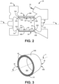
- FIG. 2 is a sectional view of CAC electrical motor assembly 20, which generally includes rotor assembly 22, stator assembly 24, coolant inlet 26, and coolant outlet 28. Rotor assembly 22 and stator assembly 24 extend generally along longitudinal axis A.
- FIG. 3 is a perspective view of stator assembly 24.
- Rotor assembly 22 includes rotating portion 32 and one or more sets of rotor windings 34, depending on whether motor assembly 20 is designed to use one-phase or three-phase power.
- Stator assembly 24 also extends generally along longitudinal axis A and at least partially encloses rotor assembly 22.
- Stator assembly 24 can include at least stationary housing 36 having at least annular inner cylindrical wall 38A and outer cylindrical wall 38B (outer wall 38B radially outward from inner wall 3 8A), as well as one or more sets of stator windings 40 in electromagnetic communication with the one or more sets of rotor windings 34 upon insertion of rotor assembly 22 into housing 36.
- a stator such as is shown in FIG. 2 would have a single wall and fins extending outward from an outer surface of the otherwise smooth wall.
- the increased surface area would increase conductive heat transfer away from the stator housing.
- advancements and increased electrical demands can still increase heat buildup to the point where the motor life is shortened.
- heat exchanger 44 can be integrally formed into stator housing 36 and includes at least a plurality of dividing walls 46 extending between inner and outer housing walls 38A, 38B.
- the plurality of dividing walls 46 can be arranged at least partially circumferentially around longitudinal axis A to define, with inner and outer walls 38A, 38B, a corresponding plurality of integral heat exchanger channels 50 arranged at least partially circumferentially around and/or axially between the one or more sets of stator windings 40.
- Each of the integral heat exchanger channels 50 can have first and second channel ends 52A, 52B extending generally axially between first and second longitudinal ends 54A, 54B of housing 36.
- a plurality of rib turbulators 56 can also be disposed on at least a channel-facing surface 58 of inner wall 3 8A. This causes repeated detachment and reattachment of the boundary layer of coolant through channels 50, thereby significantly increasing both convective cooling and conduction through wall 38A. Though omitted for clarity, rib turbulators 56 can additionally and/or alternatively be disposed on channel facing surface(s) of outer wall 38B and/or dividing walls 46.
- FIG. 2 also shows first channel end 52A of at least one of the integral heat exchanger channels in communication with an incoming source of cooling air at inlet 26, such as from an air cycle machine for an aircraft (see, e.g., FIG. 1 ).
- Second channel end 52B is in communication with discharge outlet 28. It will be appreciated that inlet 26 and outlet 28 may be reversed in some configurations relative to channel ends 52A, 52B.
- dividing walls 46 can be normal to at least one of the inner and outer walls 38A, 38B. Additionally or alternatively, therefore, a cross-section of channels 44 can be selected from round, square, variable, and combinations thereof.
- FIG. 4 is a longitudinally facing sectional view of housing 36 with integral heat exchanger 44
- FIG. 5 is a perspective / sectional view of an example channel 50, a plurality of which form integral heat exchanger 44 within housing 36.
- example channel 50 is purely axial; that is flow through channel 50 is effectively straight, over the same circumferential range between first and second channel ends 52A, 52B (generally coterminous respectively with housing longitudinal ends 54A, 54B in FIG. 3 ).
- at least one of the integral heat exchanger channels 50 can include both an axial and a circumferential component between first second channel ends 52A, 52B.
- a combination of the axial and circumferential components result in one or more of a spiral channel portion, a staggered step portion, and an undulating portion, as well as other regular or irregular patterns.
- At least one of the plurality of rib turbulators 56, along channel 50, includes a first elongated section 64 forming an acute or right angle to an adjacent dividing wall defining the channel 44 in which the at least one of the turbulators 56 is contained.
- at least some of rib turbulators 56 are chevrons with two angled elongated portions 64, 66 meeting at point or peak 68.
- Point / peak 68 can be, but is not required to be facing downstream toward outlet 28 (shown in FIG. 2 ) and/or channel end 52B.
- the housing can be formed by casting.
- a sacrificial model of the motor housing can be formed.
- This model can include a model of each of the inner cylindrical wall, the outer cylindrical wall, the plurality of dividing walls, and the plurality of rib turbulators.
- the mold which may be wax, foam, or other suitable sacrificial material, can be placed into a suitable casting medium such as but not limited to sand. Molten metal, such as an aluminum alloy, is then poured into the casting medium such that the molten metal takes the place of the sacrificial model. After cooling the poured molten metal, a solid near-net metal shape of the motor housing is formed.
Landscapes
- Engineering & Computer Science (AREA)
- Power Engineering (AREA)
- Health & Medical Sciences (AREA)
- General Health & Medical Sciences (AREA)
- Pulmonology (AREA)
- Aviation & Aerospace Engineering (AREA)
- Manufacturing & Machinery (AREA)
- Physics & Mathematics (AREA)
- Thermal Sciences (AREA)
- Motor Or Generator Frames (AREA)
- Motor Or Generator Cooling System (AREA)
Description
- The disclosure relates generally to electric motors and more specifically to electric motors with cooling features.
- With increased demands for efficiency and component life, electric motors such as those used in cabin air conditioning (CAC) systems can experience thermal issues over a shorter time frame. This can cause more frequent breakdowns and replacement, causing an aircraft to be taken out of service more often.
- Current motors utilize a monolithic stator housing with "back fins" or fins around the outer diameter of the housing. Air from the air cycle machine is passed over these fins to enhance conductive cooling of the stator windings through the single housing wall. Heat exchange systems are disclosed in
US 2014/021812 ,RU2539691 WO 2015/111018 andDE 10 2014 102632 - A stator housing is provided as defined by claim 1.
- A motor assembly is provided as defined by claim 7.
- A method is provided as defined by
claim 10. -
-
FIG. 1 is a block diagram of a typical cabin air conditioning (CAC) system. -
FIG. 2 shows an electric motor for an air cycle machine (ACM). -
FIG. 3 is a first view of an electric motor for use inFIG. 2 . -
FIG. 4 is a second view of the electric motor inFIG. 2 . -
FIG. 5 is a sectional view of a cooling channel and rib turbulators for the electric motor stator. -
FIG. 1 is a block diagram showing general elements of a cabin air conditioning (CAC) system for an aircraft.CAC system 10 includes cool air source 12 (typically external ambient air), hot compressed air source 14 (typically engine bleed air), bulk heat exchanger (HEX) 16, andpiping 18 to and from the cabin. Operations of CAC systems vary and most of the details are outside the scope of the disclosure, but the goal is to provide conditioned air to the cabin in a relatively efficient manner, while preventing freeze-up, by exchanging thermal energy between bypass air, bleed air, and recycled cabin air. In this instance,CAC system 10 is electrically operated via one ormore motor assemblies 20, details of which are shown in subsequent figures. -
FIG. 2 is a sectional view of CACelectrical motor assembly 20, which generally includesrotor assembly 22,stator assembly 24,coolant inlet 26, andcoolant outlet 28.Rotor assembly 22 andstator assembly 24 extend generally along longitudinal axis A.FIG. 3 is a perspective view ofstator assembly 24. -
Rotor assembly 22 includes rotatingportion 32 and one or more sets ofrotor windings 34, depending on whethermotor assembly 20 is designed to use one-phase or three-phase power.Stator assembly 24 also extends generally along longitudinal axis A and at least partially enclosesrotor assembly 22.Stator assembly 24 can include at leaststationary housing 36 having at least annular innercylindrical wall 38A and outercylindrical wall 38B (outer wall 38B radially outward from inner wall 3 8A), as well as one or more sets ofstator windings 40 in electromagnetic communication with the one or more sets ofrotor windings 34 upon insertion ofrotor assembly 22 intohousing 36. - Conventionally, a stator such as is shown in
FIG. 2 would have a single wall and fins extending outward from an outer surface of the otherwise smooth wall. The increased surface area would increase conductive heat transfer away from the stator housing. However, advancements and increased electrical demands can still increase heat buildup to the point where the motor life is shortened. - To improve efficiency,
heat exchanger 44 can be integrally formed intostator housing 36 and includes at least a plurality of dividingwalls 46 extending between inner andouter housing walls walls 46 can be arranged at least partially circumferentially around longitudinal axis A to define, with inner andouter walls heat exchanger channels 50 arranged at least partially circumferentially around and/or axially between the one or more sets ofstator windings 40. Each of the integralheat exchanger channels 50 can have first andsecond channel ends longitudinal ends housing 36. - To further increase cooling efficiency, a plurality of rib turbulators 56 (best seen in
FIG. 5 ) can also be disposed on at least a channel-facingsurface 58 of inner wall 3 8A. This causes repeated detachment and reattachment of the boundary layer of coolant throughchannels 50, thereby significantly increasing both convective cooling and conduction throughwall 38A. Though omitted for clarity,rib turbulators 56 can additionally and/or alternatively be disposed on channel facing surface(s) ofouter wall 38B and/or dividingwalls 46. -
FIG. 2 also showsfirst channel end 52A of at least one of the integral heat exchanger channels in communication with an incoming source of cooling air atinlet 26, such as from an air cycle machine for an aircraft (see, e.g.,FIG. 1 ).Second channel end 52B is in communication withdischarge outlet 28. It will be appreciated thatinlet 26 andoutlet 28 may be reversed in some configurations relative tochannel ends - Also in
FIG. 3 , (also visible inFIG. 4 ), it can be seen that at least part of one or both dividingwalls 46 can be normal to at least one of the inner andouter walls channels 44 can be selected from round, square, variable, and combinations thereof. - Moving to
FIGS. 4 and 5, FIG. 4 is a longitudinally facing sectional view ofhousing 36 withintegral heat exchanger 44, whileFIG. 5 is a perspective / sectional view of anexample channel 50, a plurality of which formintegral heat exchanger 44 withinhousing 36. Here,example channel 50 is purely axial; that is flow throughchannel 50 is effectively straight, over the same circumferential range between first and second channel ends 52A, 52B (generally coterminous respectively with housinglongitudinal ends FIG. 3 ). However, it will also be appreciated that in certain embodiments, at least one of the integralheat exchanger channels 50 can include both an axial and a circumferential component between first second channel ends 52A, 52B. As a result, a combination of the axial and circumferential components result in one or more of a spiral channel portion, a staggered step portion, and an undulating portion, as well as other regular or irregular patterns. - In
FIG. 5 , at least one of the plurality ofrib turbulators 56, alongchannel 50, includes a firstelongated section 64 forming an acute or right angle to an adjacent dividing wall defining thechannel 44 in which the at least one of theturbulators 56 is contained. In the example shown, at least some ofrib turbulators 56 are chevrons with two angledelongated portions peak 68. Point /peak 68 can be, but is not required to be facing downstream toward outlet 28 (shown inFIG. 2 ) and/orchannel end 52B. - To integrally form heat exchanger channels into the housing, with a plurality of rib turbulators disposed on at least a channel-facing surface of the inner wall, the housing can be formed by casting. At its simplest, a sacrificial model of the motor housing can be formed. This model can include a model of each of the inner cylindrical wall, the outer cylindrical wall, the plurality of dividing walls, and the plurality of rib turbulators. The mold, which may be wax, foam, or other suitable sacrificial material, can be placed into a suitable casting medium such as but not limited to sand. Molten metal, such as an aluminum alloy, is then poured into the casting medium such that the molten metal takes the place of the sacrificial model. After cooling the poured molten metal, a solid near-net metal shape of the motor housing is formed.
- While the invention has been described with reference to an exemplary embodiment(s), it will be understood by those skilled in the art that various changes may be made and equivalents may be substituted for elements thereof without departing from the scope of the invention as defined by the claims. In addition, many modifications may be made to adapt a particular situation or material to the teachings of the invention without departing from the scope thereof. Therefore, it is intended that the invention not be limited to the particular embodiment(s) disclosed, but that the invention will include all embodiments falling within the scope of the appended claims.
Claims (12)
- A stator housing comprising:an inner cylindrical wall (38A);an outer cylindrical wall (38B) radially disposed about the inner cylindrical wall;a plurality of dividing walls (46) extending between the inner cylindrical wall and the outer cylindrical wall defining a plurality of integral heat exchanger channels (50) extending axially through the stator housing; andhaving first and second channel ends (52A, 52B) extending generally axially between first and second longitudinal ends (54A, 54B) of the housing, wherein:the first channel end or second channel end of at least one of the integral heat exchanger channels (50) is in communication with an incoming source of cooling air (26);the other of the first and second channel ends is in communication with a discharge outlet (28); andthe incoming source of cooling air (26) is an air cycle machine foran aircraft; anda plurality of rib turbulators (56) each of which extend into one of the integral heat exchanger channels from at least one of the inner cylindrical wall, the outer cylindrical wall and one of the plurality of dividing walls,wherein at least one of the plurality of rib turbulators (56) includes a first elongated section forming an acute or right angle to an adjacent dividing wall defining the channel in which the at least one of the turbulators is contained,characterised in that the at least one of the plurality of rib turbulators includes a chevron with a peak of the chevron facing an oncoming direction of cooling air.
- The housing of claim 1, further comprising:
one or more sets of stator windings (40) positioned about the inner wall so as to be in electromagnetic communication with one or more sets of rotor windings upon insertion of a rotor assembly into the motor housing. - The housing of any of claims 1 and 2, wherein the plurality of dividing walls are normal to at least one of the inner and outer walls.
- The housing of any preceding claim, wherein a cross-section of the integral heat exchanger channels are selected from round, square, variable, and combinations thereof.
- The housing of any preceding claim, wherein at least one of the integral heat exchanger channels includes both an axial and a circumferential component between the first and second longitudinal ends.
- The housing of claim 5, wherein a combination of the axial and circumferential components result in one or more of: a spiral channel portion, a staggered step portion, and an undulating portion.
- An electric motor assembly comprising:a rotor assembly (22) extending along a longitudinal axis, the rotor assembly including a rotating portion (32) and one or more sets of rotor windings (34);a stator assembly (24) extending generally along the longitudinal axis and at least partially enclosing the rotor assembly, the stator assembly including a stator housing (36) as claimed in any preceding claim.
- The motor assembly of claim 7, wherein the first channel end or second channel end of at least one of the integral heat exchanger channels is in communication with an incoming source of cooling air (26), and the other of the first and second channel ends is in communication with a discharge outlet (28).
- The motor assembly of claim 8, wherein the incoming source of cooling air is an air cycle machine for an aircraft.
- A method of making a motor housing comprising:an inner cylindrical wall;an outer cylindrical wall annularly disposed about the inner cylindrical wall; anda heat exchanger integrally formed into the housing, the heat exchanger comprising:a plurality of dividing walls extending between the inner and outer housing walls, the plurality of dividing walls arranged at least partially circumferentially around the longitudinal axis to define, with the inner and outer walls, a corresponding plurality of integral heat exchanger channels having first and second channel ends extending generally axially between first and second longitudinal ends of the housing; whereinthe first channel end or second channel end of at least one of the integral heat exchanger channels is configured to be in communication with an incoming source of cooling air;the other of the first and second channel ends is in communication with a discharge outlet; andthe incoming source of cooling air is an air cycle machine for an aircraft; anda plurality of rib turbulators disposed on at least a channel-facing surface of the inner wall; whereinat least one of the plurality of rib turbulators includes a first elongated section forming an acute or right angle to an adjacent dividing wall defining the integral heat exchanger channel in which the at least one of the turbulators is contained such that the at least one of the plurality of rib turbulators includes a chevron with a peak of the chevron facing an oncoming direction of cooling air; wherein the method comprises:forming a sacrificial model of the motor housing, including a model of each of the inner cylindrical wall, the outer cylindrical wall, the plurality of dividing walls, and the plurality of rib turbulators;placing the mold into a suitable casting medium;pouring molten metal into the casting medium such that the molten metal takes the place of the sacrificial model; andcooling the poured molten metal, thereby providing a solid near-net metal shape of the motor housing.
- The method of claim 10, wherein the casting medium is sand.
- The method of claim 10 or 11, wherein the molten metal is an aluminum alloy.
Applications Claiming Priority (1)
| Application Number | Priority Date | Filing Date | Title |
|---|---|---|---|
| US16/510,413 US11171535B2 (en) | 2019-07-12 | 2019-07-12 | Electric motor and housing with integrated heat exchanger channels |
Publications (2)
| Publication Number | Publication Date |
|---|---|
| EP3764525A1 EP3764525A1 (en) | 2021-01-13 |
| EP3764525B1 true EP3764525B1 (en) | 2023-10-25 |
Family
ID=68887305
Family Applications (1)
| Application Number | Title | Priority Date | Filing Date |
|---|---|---|---|
| EP19215597.6A Active EP3764525B1 (en) | 2019-07-12 | 2019-12-12 | Electric motor and housing with integrated heat exchanger channels |
Country Status (2)
| Country | Link |
|---|---|
| US (1) | US11171535B2 (en) |
| EP (1) | EP3764525B1 (en) |
Families Citing this family (1)
| Publication number | Priority date | Publication date | Assignee | Title |
|---|---|---|---|---|
| US11988138B2 (en) | 2022-09-13 | 2024-05-21 | Hamilton Sundstrand Corporation | Hybrid propulsion system with integrated air-cooling system |
Family Cites Families (24)
| Publication number | Priority date | Publication date | Assignee | Title |
|---|---|---|---|---|
| JPS55144745A (en) * | 1979-04-25 | 1980-11-11 | Toshiba Corp | Salient-pole type rotary machine |
| US5331238A (en) * | 1993-03-01 | 1994-07-19 | Sundstrand Corporation | Apparatus for containment and cooling of a core within a housing |
| US5869912A (en) * | 1997-07-25 | 1999-02-09 | General Electric Co. | Direct-cooled dynamoelectric machine stator core with enhanced heat transfer capability |
| DE59806099D1 (en) | 1997-08-26 | 2002-12-05 | Siemens Ag | Cast part of an electric motor |
| US6317963B1 (en) * | 1999-08-03 | 2001-11-20 | Hamilton Sundstrand Corporation | One piece, extruded housing for a dynamoelectric machine |
| US7701096B2 (en) * | 2004-10-01 | 2010-04-20 | Kabushiki Kaisha Toshiba | Totally enclosed type main drive motor for vehicle |
| US7633194B2 (en) * | 2006-10-26 | 2009-12-15 | Gm Global Technology Operations, Inc. | Apparatus for cooling stator lamination stacks of electrical machines |
| JP4861840B2 (en) * | 2007-01-26 | 2012-01-25 | アイシン・エィ・ダブリュ株式会社 | Heating element cooling structure and driving device |
| US7626292B2 (en) | 2007-07-03 | 2009-12-01 | Caterpillar Inc. | Cast groove electric motor/generator cooling mechanism |
| DE112010001474T5 (en) * | 2009-03-31 | 2012-07-05 | Baker Hughes Inc. | Improved heat transfer through an electric submersible pump motor |
| US8704414B2 (en) * | 2011-09-14 | 2014-04-22 | General Electric Company | Machines and methods and assembly for same |
| US8912695B2 (en) | 2012-07-18 | 2014-12-16 | Siemens Industry, Inc. | Induction motor auxiliary cooling system |
| DE102012017293B4 (en) * | 2012-08-27 | 2020-08-06 | Magna Pt B.V. & Co. Kg | Electrical machine for a motor vehicle drive train |
| CN103683634A (en) | 2012-09-12 | 2014-03-26 | 庄嘉明 | Base with cooling fins, molding method, and motor with the base |
| US20140217841A1 (en) * | 2012-12-14 | 2014-08-07 | Brammo, Inc. | High efficiency, low coolant flow electric motor coolant system |
| JP5642821B2 (en) * | 2013-02-26 | 2014-12-17 | ファナック株式会社 | Cooling jacket having grooves for allowing refrigerant to pass through, stator provided with cooling jacket, and rotating electrical machine provided with cooling jacket |
| DE102014102632A1 (en) | 2013-03-04 | 2014-09-04 | Remy Technologies Llc | Liquid-cooled rotary electric machine, e.g., electric generators, has flow path for liquid coolant through machine which progresses in opposite directions parallel to central axis as flow path traverses heat transfer surface |
| US9680351B2 (en) * | 2013-03-15 | 2017-06-13 | Ingersoll-Rand Company | Electrical machine having cooling features |
| SI24669A (en) | 2014-01-26 | 2015-09-30 | Skiping D.O.O. | A radiator of electro motor with a set of aligned dot ribs |
| RU2539691C1 (en) | 2014-03-05 | 2015-01-27 | Федеральное государственное бюджетное образовательное учреждение высшего профессионального образования "Национальный исследовательский университет "МЭИ" | System of closed electrical machine cooling |
| US10554091B2 (en) * | 2014-08-22 | 2020-02-04 | Regal Beloit America, Inc. | Electric machine with rotor, stator and housing cooling passages |
| US9920635B2 (en) * | 2014-09-09 | 2018-03-20 | Honeywell International Inc. | Turbine blades and methods of forming turbine blades having lifted rib turbulator structures |
| US20160294231A1 (en) * | 2015-04-02 | 2016-10-06 | Hamilton Sundstrand Corporation | Stator heat transfer feature |
| DE102016015535A1 (en) | 2016-12-19 | 2018-06-21 | Ziehl-Abegg Se | Cooling device of an electric motor and electric motor with cooling device |
-
2019
- 2019-07-12 US US16/510,413 patent/US11171535B2/en active Active
- 2019-12-12 EP EP19215597.6A patent/EP3764525B1/en active Active
Also Published As
| Publication number | Publication date |
|---|---|
| US11171535B2 (en) | 2021-11-09 |
| EP3764525A1 (en) | 2021-01-13 |
| US20210013767A1 (en) | 2021-01-14 |
Similar Documents
| Publication | Publication Date | Title |
|---|---|---|
| US12592606B2 (en) | Axial flux motor with air cooling system | |
| EP2058926B1 (en) | Enhanced motor cooling system | |
| US9729020B2 (en) | Motor stator having channels used for cooling and method of providing the channels | |
| EP2369723B1 (en) | Cooling arrangement for an electric machine | |
| US11005316B2 (en) | Electrical drive device for a motor vehicle | |
| US9413208B2 (en) | Enhanced cooling of enclosed air cooled high power motors | |
| EP3487042B1 (en) | Electric motor | |
| US20170237316A1 (en) | Rotor Shaft Arrangement and Method for Manufacturing the Same | |
| CN111200335A (en) | Temperature control assembly for an electric machine | |
| CN102447342B (en) | Housing of rotating motor | |
| CN103038983A (en) | Electric machine cooling system and method | |
| EP3965266B1 (en) | Electric machine rotor cooling cartridge | |
| EP3269946B1 (en) | Rotary machine heat sink | |
| CN113454878A (en) | Integrated stator cooling jacket system | |
| CN111435802B (en) | Cooling shell | |
| WO2014093759A1 (en) | High efficiency, low coolant flow electric motor coolant system | |
| EP4436009A1 (en) | Motor radiator | |
| JP3650351B2 (en) | Cage type induction motor rotor and cage type induction motor | |
| EP3412890B1 (en) | Rotating machine and method for manufacturing casing for rotating machine | |
| US11171535B2 (en) | Electric motor and housing with integrated heat exchanger channels | |
| EP3245711B1 (en) | Rotary electric machine | |
| CN116581914A (en) | Device and method for cooling end windings in rotating electric machines | |
| CN113853728B (en) | Motor | |
| CN104283347A (en) | Rotating electric machine | |
| US20240388162A1 (en) | Motor radiator |
Legal Events
| Date | Code | Title | Description |
|---|---|---|---|
| PUAI | Public reference made under article 153(3) epc to a published international application that has entered the european phase |
Free format text: ORIGINAL CODE: 0009012 |
|
| STAA | Information on the status of an ep patent application or granted ep patent |
Free format text: STATUS: THE APPLICATION HAS BEEN PUBLISHED |
|
| AK | Designated contracting states |
Kind code of ref document: A1 Designated state(s): AL AT BE BG CH CY CZ DE DK EE ES FI FR GB GR HR HU IE IS IT LI LT LU LV MC MK MT NL NO PL PT RO RS SE SI SK SM TR |
|
| AX | Request for extension of the european patent |
Extension state: BA ME |
|
| STAA | Information on the status of an ep patent application or granted ep patent |
Free format text: STATUS: REQUEST FOR EXAMINATION WAS MADE |
|
| 17P | Request for examination filed |
Effective date: 20210713 |
|
| RBV | Designated contracting states (corrected) |
Designated state(s): AL AT BE BG CH CY CZ DE DK EE ES FI FR GB GR HR HU IE IS IT LI LT LU LV MC MK MT NL NO PL PT RO RS SE SI SK SM TR |
|
| RIC1 | Information provided on ipc code assigned before grant |
Ipc: H02K 5/20 20060101ALI20230324BHEP Ipc: H02K 15/14 20060101ALI20230324BHEP Ipc: H02K 9/18 20060101AFI20230324BHEP |
|
| GRAP | Despatch of communication of intention to grant a patent |
Free format text: ORIGINAL CODE: EPIDOSNIGR1 |
|
| STAA | Information on the status of an ep patent application or granted ep patent |
Free format text: STATUS: GRANT OF PATENT IS INTENDED |
|
| INTG | Intention to grant announced |
Effective date: 20230523 |
|
| GRAS | Grant fee paid |
Free format text: ORIGINAL CODE: EPIDOSNIGR3 |
|
| GRAA | (expected) grant |
Free format text: ORIGINAL CODE: 0009210 |
|
| STAA | Information on the status of an ep patent application or granted ep patent |
Free format text: STATUS: THE PATENT HAS BEEN GRANTED |
|
| AK | Designated contracting states |
Kind code of ref document: B1 Designated state(s): AL AT BE BG CH CY CZ DE DK EE ES FI FR GB GR HR HU IE IS IT LI LT LU LV MC MK MT NL NO PL PT RO RS SE SI SK SM TR |
|
| REG | Reference to a national code |
Ref country code: GB Ref legal event code: FG4D |
|
| REG | Reference to a national code |
Ref country code: CH Ref legal event code: EP |
|
| REG | Reference to a national code |
Ref country code: DE Ref legal event code: R096 Ref document number: 602019039971 Country of ref document: DE |
|
| REG | Reference to a national code |
Ref country code: IE Ref legal event code: FG4D |
|
| REG | Reference to a national code |
Ref country code: LT Ref legal event code: MG9D |
|
| REG | Reference to a national code |
Ref country code: NL Ref legal event code: MP Effective date: 20231025 |
|
| REG | Reference to a national code |
Ref country code: AT Ref legal event code: MK05 Ref document number: 1625664 Country of ref document: AT Kind code of ref document: T Effective date: 20231025 |
|
| PG25 | Lapsed in a contracting state [announced via postgrant information from national office to epo] |
Ref country code: NL Free format text: LAPSE BECAUSE OF FAILURE TO SUBMIT A TRANSLATION OF THE DESCRIPTION OR TO PAY THE FEE WITHIN THE PRESCRIBED TIME-LIMIT Effective date: 20231025 |
|
| PG25 | Lapsed in a contracting state [announced via postgrant information from national office to epo] |
Ref country code: GR Free format text: LAPSE BECAUSE OF FAILURE TO SUBMIT A TRANSLATION OF THE DESCRIPTION OR TO PAY THE FEE WITHIN THE PRESCRIBED TIME-LIMIT Effective date: 20240126 |
|
| PG25 | Lapsed in a contracting state [announced via postgrant information from national office to epo] |
Ref country code: IS Free format text: LAPSE BECAUSE OF FAILURE TO SUBMIT A TRANSLATION OF THE DESCRIPTION OR TO PAY THE FEE WITHIN THE PRESCRIBED TIME-LIMIT Effective date: 20240225 |
|
| PG25 | Lapsed in a contracting state [announced via postgrant information from national office to epo] |
Ref country code: LT Free format text: LAPSE BECAUSE OF FAILURE TO SUBMIT A TRANSLATION OF THE DESCRIPTION OR TO PAY THE FEE WITHIN THE PRESCRIBED TIME-LIMIT Effective date: 20231025 |
|
| PG25 | Lapsed in a contracting state [announced via postgrant information from national office to epo] |
Ref country code: AT Free format text: LAPSE BECAUSE OF FAILURE TO SUBMIT A TRANSLATION OF THE DESCRIPTION OR TO PAY THE FEE WITHIN THE PRESCRIBED TIME-LIMIT Effective date: 20231025 |
|
| PG25 | Lapsed in a contracting state [announced via postgrant information from national office to epo] |
Ref country code: ES Free format text: LAPSE BECAUSE OF FAILURE TO SUBMIT A TRANSLATION OF THE DESCRIPTION OR TO PAY THE FEE WITHIN THE PRESCRIBED TIME-LIMIT Effective date: 20231025 |
|
| PG25 | Lapsed in a contracting state [announced via postgrant information from national office to epo] |
Ref country code: LT Free format text: LAPSE BECAUSE OF FAILURE TO SUBMIT A TRANSLATION OF THE DESCRIPTION OR TO PAY THE FEE WITHIN THE PRESCRIBED TIME-LIMIT Effective date: 20231025 Ref country code: IS Free format text: LAPSE BECAUSE OF FAILURE TO SUBMIT A TRANSLATION OF THE DESCRIPTION OR TO PAY THE FEE WITHIN THE PRESCRIBED TIME-LIMIT Effective date: 20240225 Ref country code: GR Free format text: LAPSE BECAUSE OF FAILURE TO SUBMIT A TRANSLATION OF THE DESCRIPTION OR TO PAY THE FEE WITHIN THE PRESCRIBED TIME-LIMIT Effective date: 20240126 Ref country code: ES Free format text: LAPSE BECAUSE OF FAILURE TO SUBMIT A TRANSLATION OF THE DESCRIPTION OR TO PAY THE FEE WITHIN THE PRESCRIBED TIME-LIMIT Effective date: 20231025 Ref country code: BG Free format text: LAPSE BECAUSE OF FAILURE TO SUBMIT A TRANSLATION OF THE DESCRIPTION OR TO PAY THE FEE WITHIN THE PRESCRIBED TIME-LIMIT Effective date: 20240125 Ref country code: AT Free format text: LAPSE BECAUSE OF FAILURE TO SUBMIT A TRANSLATION OF THE DESCRIPTION OR TO PAY THE FEE WITHIN THE PRESCRIBED TIME-LIMIT Effective date: 20231025 Ref country code: PT Free format text: LAPSE BECAUSE OF FAILURE TO SUBMIT A TRANSLATION OF THE DESCRIPTION OR TO PAY THE FEE WITHIN THE PRESCRIBED TIME-LIMIT Effective date: 20240226 |
|
| PG25 | Lapsed in a contracting state [announced via postgrant information from national office to epo] |
Ref country code: SE Free format text: LAPSE BECAUSE OF FAILURE TO SUBMIT A TRANSLATION OF THE DESCRIPTION OR TO PAY THE FEE WITHIN THE PRESCRIBED TIME-LIMIT Effective date: 20231025 Ref country code: RS Free format text: LAPSE BECAUSE OF FAILURE TO SUBMIT A TRANSLATION OF THE DESCRIPTION OR TO PAY THE FEE WITHIN THE PRESCRIBED TIME-LIMIT Effective date: 20231025 Ref country code: PL Free format text: LAPSE BECAUSE OF FAILURE TO SUBMIT A TRANSLATION OF THE DESCRIPTION OR TO PAY THE FEE WITHIN THE PRESCRIBED TIME-LIMIT Effective date: 20231025 Ref country code: NO Free format text: LAPSE BECAUSE OF FAILURE TO SUBMIT A TRANSLATION OF THE DESCRIPTION OR TO PAY THE FEE WITHIN THE PRESCRIBED TIME-LIMIT Effective date: 20240125 Ref country code: LV Free format text: LAPSE BECAUSE OF FAILURE TO SUBMIT A TRANSLATION OF THE DESCRIPTION OR TO PAY THE FEE WITHIN THE PRESCRIBED TIME-LIMIT Effective date: 20231025 Ref country code: HR Free format text: LAPSE BECAUSE OF FAILURE TO SUBMIT A TRANSLATION OF THE DESCRIPTION OR TO PAY THE FEE WITHIN THE PRESCRIBED TIME-LIMIT Effective date: 20231025 |
|
| PG25 | Lapsed in a contracting state [announced via postgrant information from national office to epo] |
Ref country code: DK Free format text: LAPSE BECAUSE OF FAILURE TO SUBMIT A TRANSLATION OF THE DESCRIPTION OR TO PAY THE FEE WITHIN THE PRESCRIBED TIME-LIMIT Effective date: 20231025 |
|
| PG25 | Lapsed in a contracting state [announced via postgrant information from national office to epo] |
Ref country code: CZ Free format text: LAPSE BECAUSE OF FAILURE TO SUBMIT A TRANSLATION OF THE DESCRIPTION OR TO PAY THE FEE WITHIN THE PRESCRIBED TIME-LIMIT Effective date: 20231025 |
|
| REG | Reference to a national code |
Ref country code: DE Ref legal event code: R097 Ref document number: 602019039971 Country of ref document: DE |
|
| PG25 | Lapsed in a contracting state [announced via postgrant information from national office to epo] |
Ref country code: SK Free format text: LAPSE BECAUSE OF FAILURE TO SUBMIT A TRANSLATION OF THE DESCRIPTION OR TO PAY THE FEE WITHIN THE PRESCRIBED TIME-LIMIT Effective date: 20231025 |
|
| PG25 | Lapsed in a contracting state [announced via postgrant information from national office to epo] |
Ref country code: SM Free format text: LAPSE BECAUSE OF FAILURE TO SUBMIT A TRANSLATION OF THE DESCRIPTION OR TO PAY THE FEE WITHIN THE PRESCRIBED TIME-LIMIT Effective date: 20231025 Ref country code: SK Free format text: LAPSE BECAUSE OF FAILURE TO SUBMIT A TRANSLATION OF THE DESCRIPTION OR TO PAY THE FEE WITHIN THE PRESCRIBED TIME-LIMIT Effective date: 20231025 Ref country code: RO Free format text: LAPSE BECAUSE OF FAILURE TO SUBMIT A TRANSLATION OF THE DESCRIPTION OR TO PAY THE FEE WITHIN THE PRESCRIBED TIME-LIMIT Effective date: 20231025 Ref country code: IT Free format text: LAPSE BECAUSE OF FAILURE TO SUBMIT A TRANSLATION OF THE DESCRIPTION OR TO PAY THE FEE WITHIN THE PRESCRIBED TIME-LIMIT Effective date: 20231025 Ref country code: EE Free format text: LAPSE BECAUSE OF FAILURE TO SUBMIT A TRANSLATION OF THE DESCRIPTION OR TO PAY THE FEE WITHIN THE PRESCRIBED TIME-LIMIT Effective date: 20231025 Ref country code: DK Free format text: LAPSE BECAUSE OF FAILURE TO SUBMIT A TRANSLATION OF THE DESCRIPTION OR TO PAY THE FEE WITHIN THE PRESCRIBED TIME-LIMIT Effective date: 20231025 Ref country code: CZ Free format text: LAPSE BECAUSE OF FAILURE TO SUBMIT A TRANSLATION OF THE DESCRIPTION OR TO PAY THE FEE WITHIN THE PRESCRIBED TIME-LIMIT Effective date: 20231025 |
|
| REG | Reference to a national code |
Ref country code: CH Ref legal event code: PL |
|
| PG25 | Lapsed in a contracting state [announced via postgrant information from national office to epo] |
Ref country code: LU Free format text: LAPSE BECAUSE OF NON-PAYMENT OF DUE FEES Effective date: 20231212 |
|
| PG25 | Lapsed in a contracting state [announced via postgrant information from national office to epo] |
Ref country code: MC Free format text: LAPSE BECAUSE OF FAILURE TO SUBMIT A TRANSLATION OF THE DESCRIPTION OR TO PAY THE FEE WITHIN THE PRESCRIBED TIME-LIMIT Effective date: 20231025 |
|
| REG | Reference to a national code |
Ref country code: BE Ref legal event code: MM Effective date: 20231231 |
|
| PG25 | Lapsed in a contracting state [announced via postgrant information from national office to epo] |
Ref country code: MC Free format text: LAPSE BECAUSE OF FAILURE TO SUBMIT A TRANSLATION OF THE DESCRIPTION OR TO PAY THE FEE WITHIN THE PRESCRIBED TIME-LIMIT Effective date: 20231025 Ref country code: LU Free format text: LAPSE BECAUSE OF NON-PAYMENT OF DUE FEES Effective date: 20231212 |
|
| PLBE | No opposition filed within time limit |
Free format text: ORIGINAL CODE: 0009261 |
|
| STAA | Information on the status of an ep patent application or granted ep patent |
Free format text: STATUS: NO OPPOSITION FILED WITHIN TIME LIMIT |
|
| 26N | No opposition filed |
Effective date: 20240726 |
|
| REG | Reference to a national code |
Ref country code: IE Ref legal event code: MM4A |
|
| PG25 | Lapsed in a contracting state [announced via postgrant information from national office to epo] |
Ref country code: IE Free format text: LAPSE BECAUSE OF NON-PAYMENT OF DUE FEES Effective date: 20231212 |
|
| PG25 | Lapsed in a contracting state [announced via postgrant information from national office to epo] |
Ref country code: BE Free format text: LAPSE BECAUSE OF NON-PAYMENT OF DUE FEES Effective date: 20231231 |
|
| PG25 | Lapsed in a contracting state [announced via postgrant information from national office to epo] |
Ref country code: CH Free format text: LAPSE BECAUSE OF NON-PAYMENT OF DUE FEES Effective date: 20231231 |
|
| PG25 | Lapsed in a contracting state [announced via postgrant information from national office to epo] |
Ref country code: SI Free format text: LAPSE BECAUSE OF FAILURE TO SUBMIT A TRANSLATION OF THE DESCRIPTION OR TO PAY THE FEE WITHIN THE PRESCRIBED TIME-LIMIT Effective date: 20231025 |
|
| PG25 | Lapsed in a contracting state [announced via postgrant information from national office to epo] |
Ref country code: SI Free format text: LAPSE BECAUSE OF FAILURE TO SUBMIT A TRANSLATION OF THE DESCRIPTION OR TO PAY THE FEE WITHIN THE PRESCRIBED TIME-LIMIT Effective date: 20231025 Ref country code: IE Free format text: LAPSE BECAUSE OF NON-PAYMENT OF DUE FEES Effective date: 20231212 Ref country code: CH Free format text: LAPSE BECAUSE OF NON-PAYMENT OF DUE FEES Effective date: 20231231 Ref country code: BE Free format text: LAPSE BECAUSE OF NON-PAYMENT OF DUE FEES Effective date: 20231231 |
|
| PG25 | Lapsed in a contracting state [announced via postgrant information from national office to epo] |
Ref country code: FI Free format text: LAPSE BECAUSE OF FAILURE TO SUBMIT A TRANSLATION OF THE DESCRIPTION OR TO PAY THE FEE WITHIN THE PRESCRIBED TIME-LIMIT Effective date: 20231025 |
|
| PG25 | Lapsed in a contracting state [announced via postgrant information from national office to epo] |
Ref country code: CY Free format text: LAPSE BECAUSE OF FAILURE TO SUBMIT A TRANSLATION OF THE DESCRIPTION OR TO PAY THE FEE WITHIN THE PRESCRIBED TIME-LIMIT; INVALID AB INITIO Effective date: 20191212 |
|
| PG25 | Lapsed in a contracting state [announced via postgrant information from national office to epo] |
Ref country code: HU Free format text: LAPSE BECAUSE OF FAILURE TO SUBMIT A TRANSLATION OF THE DESCRIPTION OR TO PAY THE FEE WITHIN THE PRESCRIBED TIME-LIMIT; INVALID AB INITIO Effective date: 20191212 |
|
| PG25 | Lapsed in a contracting state [announced via postgrant information from national office to epo] |
Ref country code: TR Free format text: LAPSE BECAUSE OF FAILURE TO SUBMIT A TRANSLATION OF THE DESCRIPTION OR TO PAY THE FEE WITHIN THE PRESCRIBED TIME-LIMIT Effective date: 20231025 |
|
| PGFP | Annual fee paid to national office [announced via postgrant information from national office to epo] |
Ref country code: DE Payment date: 20251126 Year of fee payment: 7 |
|
| PGFP | Annual fee paid to national office [announced via postgrant information from national office to epo] |
Ref country code: GB Payment date: 20251120 Year of fee payment: 7 |
|
| PGFP | Annual fee paid to national office [announced via postgrant information from national office to epo] |
Ref country code: FR Payment date: 20251120 Year of fee payment: 7 |
|
| P01 | Opt-out of the competence of the unified patent court (upc) registered |
Free format text: CASE NUMBER: UPC_APP_0018954_3764525/2025 Effective date: 20251222 |