EP3764480A1 - Lever-type connector - Google Patents
Lever-type connector Download PDFInfo
- Publication number
- EP3764480A1 EP3764480A1 EP20183441.3A EP20183441A EP3764480A1 EP 3764480 A1 EP3764480 A1 EP 3764480A1 EP 20183441 A EP20183441 A EP 20183441A EP 3764480 A1 EP3764480 A1 EP 3764480A1
- Authority
- EP
- European Patent Office
- Prior art keywords
- housing
- lever
- temporary locking
- temporary
- arm portion
- Prior art date
- Legal status (The legal status is an assumption and is not a legal conclusion. Google has not performed a legal analysis and makes no representation as to the accuracy of the status listed.)
- Granted
Links
Images

Classifications
-
- H—ELECTRICITY
- H01—ELECTRIC ELEMENTS
- H01R—ELECTRICALLY-CONDUCTIVE CONNECTIONS; STRUCTURAL ASSOCIATIONS OF A PLURALITY OF MUTUALLY-INSULATED ELECTRICAL CONNECTING ELEMENTS; COUPLING DEVICES; CURRENT COLLECTORS
- H01R13/00—Details of coupling devices of the kinds covered by groups H01R12/70 or H01R24/00 - H01R33/00
- H01R13/62—Means for facilitating engagement or disengagement of coupling parts or for holding them in engagement
- H01R13/629—Additional means for facilitating engagement or disengagement of coupling parts, e.g. aligning or guiding means, levers, gas pressure electrical locking indicators, manufacturing tolerances
- H01R13/62933—Comprising exclusively pivoting lever
- H01R13/62955—Pivoting lever comprising supplementary/additional locking means
-
- H—ELECTRICITY
- H01—ELECTRIC ELEMENTS
- H01R—ELECTRICALLY-CONDUCTIVE CONNECTIONS; STRUCTURAL ASSOCIATIONS OF A PLURALITY OF MUTUALLY-INSULATED ELECTRICAL CONNECTING ELEMENTS; COUPLING DEVICES; CURRENT COLLECTORS
- H01R13/00—Details of coupling devices of the kinds covered by groups H01R12/70 or H01R24/00 - H01R33/00
- H01R13/62—Means for facilitating engagement or disengagement of coupling parts or for holding them in engagement
- H01R13/629—Additional means for facilitating engagement or disengagement of coupling parts, e.g. aligning or guiding means, levers, gas pressure electrical locking indicators, manufacturing tolerances
- H01R13/62933—Comprising exclusively pivoting lever
- H01R13/62938—Pivoting lever comprising own camming means
-
- H—ELECTRICITY
- H01—ELECTRIC ELEMENTS
- H01R—ELECTRICALLY-CONDUCTIVE CONNECTIONS; STRUCTURAL ASSOCIATIONS OF A PLURALITY OF MUTUALLY-INSULATED ELECTRICAL CONNECTING ELEMENTS; COUPLING DEVICES; CURRENT COLLECTORS
- H01R24/00—Two-part coupling devices, or either of their cooperating parts, characterised by their overall structure
- H01R24/005—Two-part coupling devices, or either of their cooperating parts, characterised by their overall structure requiring successive relative motions to complete the coupling, e.g. bayonet type
-
- H—ELECTRICITY
- H01—ELECTRIC ELEMENTS
- H01R—ELECTRICALLY-CONDUCTIVE CONNECTIONS; STRUCTURAL ASSOCIATIONS OF A PLURALITY OF MUTUALLY-INSULATED ELECTRICAL CONNECTING ELEMENTS; COUPLING DEVICES; CURRENT COLLECTORS
- H01R13/00—Details of coupling devices of the kinds covered by groups H01R12/70 or H01R24/00 - H01R33/00
- H01R13/62—Means for facilitating engagement or disengagement of coupling parts or for holding them in engagement
- H01R13/627—Snap or like fastening
- H01R13/6271—Latching means integral with the housing
- H01R13/6273—Latching means integral with the housing comprising two latching arms
Definitions
- the present invention relates to a lever-type connector in which connectors can be fitted to each other with low insertion force due to rotation of a lever.
- JP 2017-168391 A discloses this type of lever-type connector.
- This lever-type connector includes a housing having a fitting cylindrical portion that is fitted into and removed from a hood portion of a mating housing.
- the lever-type connector includes a lever.
- the lever is rotatably supported, via bearings, by support shafts on both sides of the fitting cylindrical portion of the housing, and has a cam groove that engages with a cam follower arranged in the hood portion of the mating housing. By rotating the operating portion, the cam groove is engaged with the cam follower and thus the housings are fitted to each other.
- a shaft center of the cam follower in the mating housing, the cam follower being engaged with the cam groove of the lever, is shifted in position toward the operating portion, which is upward of a shaft center of the bearing of the lever in a vertical direction (direction orthogonal to fitting direction of housing and mating housing).
- the cam follower of the mating housing abuts against a gentle slope of the cam groove of the lever. Therefore, when the mating housing is pushed further into the housing from a temporary set state of both housings, the lever may rotate, and a female terminal of the housing and a male terminal of the mating housing may be fitted into a position where these terminals can be electrically conducted.
- the present invention has been achieved in order to solve the above problems, and an object of the invention is to provide a lever-type connector that can prevent rotation of a lever when both housings are temporarily set, and that can prevent electrical conduction between terminals of the housings before the lever is operated.
- a lever-type connector includes a mating housing having a cam boss, a housing that is fitted into and removed from the mating housing, and a lever that is rotatably supported by the housing via a support shaft, has a cam groove engaging with the cam boss, and is rotated from a temporary locking position to cause the cam groove to engage with the cam boss, thus moving the mating housing toward the housing and fitting the mating housing and the housing to each other.
- the lever includes a temporary locking arm portion that has a temporary locking portion and is elastically deformable, and the housing includes a temporarily locked portion that is temporarily locked to and unlocked from the temporary locking portion of the temporary locking arm portion.
- the mating housing includes a release rib portion that releases a temporary locking state of the temporary locking portion of the temporary locking arm portion and the temporarily locked portion of the housing
- the cam groove of the lever includes a boss receiving portion that receives the cam boss when the temporary locking state of the temporary locking portion of the temporary locking arm portion and the temporarily locked portion of the housing is released in a state where the mating housing and the housing are temporarily set.
- a lever-type connector according to a second aspect of the present invention relates to the lever-type connector according to the first aspect.
- a projecting temporary set beak portion is formed on a lower surface of the release rib portion, and the housing includes a temporary set arm portion that prevents the mating housing from being removed from the housing, the mating housing and the housing being in a temporary set state when a temporary locking state of the temporary locking portion of the temporary locking arm portion of the lever and the temporarily locked portion of the housing is released.
- a distal end of the temporary set arm portion includes a projection that slides along the lower surface of the release rib portion, and the temporary locking state of the temporary locking portion of the temporary locking arm portion of the lever and the temporarily locked portion of the housing is released at a position where the projection is across the temporary set beak portion from the lower surface of the release rib portion.
- a lever-type connector 10 includes a male housing (mating housing) 11 that is made of synthetic resin and has a cam boss 12, a female housing (housing) 20 that is made of synthetic resin and is fitted into and removed from the male housing 11, and a lever 30 made of synthetic resin.
- the lever 30 is rotatably supported by a support shaft 23 arranged in the female housing 20, and has a cam groove 35 that engages with the cam boss 12 of the male housing 11.
- the cam groove 35 is engaged with the cam boss 12 and thus the male housing 11 is made to move toward the female housing 20, so that the male housing 11 and the female housing 20 are fitted to each other.
- the direction in which the male housing 11 and the female housing 20 are fitted to each other is referred to as "fitting direction”
- the direction orthogonal to the fitting direction, in which the cam bosses 12 formed on both side surfaces 11b, 11b of the male housing 11 are connected is referred to as “width direction”
- the vertical direction in the figure orthogonal to the fitting direction and the width direction, in which an upper surface 21c and a bottom surface of the female housing 20 are connected is referred to as “height direction”.
- the directions such as “longitudinal” and “vertical” are defined for convenience of explanation, and do not limit the actual mounting orientations of the respective elements.
- the male housing 11 has, on the front side (one fitting-direction side), a hood portion 11a that is inserted into a hood portion 22 of the female housing 20.
- the cylindrical cam boss 12 is integrally formed in a projecting manner at a center in the height direction of each of the side surfaces 11b, 11b of the male housing 11 in the width direction.
- a release rib portion 13 extending in the longitudinal direction (fitting direction) is integrally formed in a projecting manner under (on one height-direction side of) the cam boss 12 on each of the side surfaces 11b, 11b of the male housing 11.
- a distal end 13a of the release rib portion 13 on one fitting-direction side functions as a release portion that releases a temporary locking state of a cutaway portion (temporarily locked portion) 25 of the female housing 20 and a temporary locking projection (temporary locking portion) 36a of a temporary locking arm portion 36 of the lever 30, which will be described later.
- a trapezoidal temporary set beak portion 14 is integrally formed in a projecting manner at a center in the fitting direction of a lower surface 13c of the release rib portion 13 in the height direction. As illustrated in FIG. 2 , a slope 13b is formed on the back side (other fitting-direction side) of the distal end 13a of the release rib portion 13.
- the trapezoidal temporary set beak portion 14 has a front slope 14a on one fitting-direction side, a straight surface 14b, and a back slope 14c on the other fitting-direction side.
- a tab portion of a male terminal (terminal) which is not illustrated, is exposed.
- the female housing 20 includes a block-like housing main body 21 having a plurality of terminal accommodating chambers 21a, and the hood portion 22 that is integrally formed in a projecting manner on the front side (other fitting-direction side) of the housing main body 21 and into which the hood portion 11a of the male housing 11 is fitted.
- the support shaft 23 is integrally formed in a projecting manner at a center in the height direction of each of side surfaces 21b, 21b of the housing main body 21 in the width direction.
- An elastically deformable locking arm portion 24 is integrally formed in a projecting manner on the front side (other fitting-direction side) at a center in the width direction of the upper surface 21c of the housing main body 21 in the height direction.
- a receiving portion 24b is integrally formed in a projecting manner at a free end (distal end) 24a of the locking arm portion 24.
- the substantially rectangular cutaway portion (temporarily locked portion) 25 is formed on the front side (other fitting-direction side) at a center in the height direction of each of side portions of the hood portion 22 of the female housing 20 in the width direction. That is, the temporary locking projection 36a of the temporary locking arm portion 36 of the lever 30 to be described later is temporarily locked to or unlocked from a lower edge 25a of each cutaway portion 25 in the height direction.
- the temporary locking projection 36a of the temporary locking arm portion 36 is temporarily locked to the lower edge 25a of the cutaway portion 25, the lever 30 is held at a temporary lock position.
- a double-supported temporary set arm portion 26 is integrally formed to be elastically deformable on the front side (other fitting-direction side) of the lower edge 25a of each cutaway portion 25.
- a projection 26a is formed on an upper surface (other height-direction side) closer to the front side (other fitting-direction side) of the temporary set arm portion 26. The projection 26a slides along the lower surface 13c of the release rib portion 13.
- the temporary set arm portion 26 functions to prevent the male housing 11 from being removed from the female housing 20, the male housing 11 and the female housing 20 being in a temporary set state when the lever 30 is unlocked from the temporary locking position, until the projection 26a slides along the lower surface 13c of the release rib portion 13 and reaches a position across the temporary set beak portion 14.
- a rectangular cylindrical front holder 29 that is made of synthetic resin and has a front wall portion 29a is fitted to the periphery of a plurality of the terminal accommodating chambers 21a of the housing main body 21 in the hood portion 22 of the female housing 20.
- a rectangular annular packing 28 made of rubber is interposed between the hood portion 22 of the female housing 20 and the periphery of the terminal accommodating chambers 21 a of the housing main body 21.
- the front wall portion 29a of the front holder 29 includes a plurality of rectangular openings 29b communicating with the plurality of terminal accommodating chambers 21a of the housing main body 21.
- a female terminal (not illustrated) is accommodated in the terminal accommodating chamber 21a of the housing main body 21.
- the female terminal accommodated in the terminal accommodating chamber 21a of the housing main body 21 is held by a lance (not illustrated) arranged in the terminal accommodating chamber 21a.
- the lever 30 includes the operating portion 31 and a pair of arm portions 32, 32 extending from both sides of the operating portion 31 in the width direction.
- a locking projection 33 is formed on the lower side (one height-direction side) at a center in the width direction of the operating portion 31 of the lever 30.
- the locking projection 33 is locked to the receiving portion 24b of the locking arm portion 24 in the female housing 20.
- This locking brings about a rotation restricting state where the rotation of the lever 30 is restricted.
- the lock state of the locking projection 33 of the lever 30 and the receiving portion 24b of the locking arm portion 24 in the female housing 20 is released by pressing the side of the free end 24a of the locking arm portion 24 downward (one height-direction side) so as to detach the receiving portion 24b of the locking arm portion 24 from the locking projection 33.
- a bearing hole 34 that is rotatably supported by the support shaft 23 is formed on the back side (one fitting-direction side) of each arm portion 32 of the lever 30.
- the arcuate recessed cam groove 35 is formed in each of the inner sides of the arm portions 32 (sides at which arm portions 32 face to each other in width direction).
- the temporary locking arm portion 36 that is elastically deformable and has the temporary locking projection (temporary locking portion) 36a at its distal end is integrally formed on each of the lower sides (one height-direction side) of the arm portions 32.
- the temporary locking state of the temporary locking projection 36a of the temporary locking arm portion 36 in the lever 30 and the lower edge 25a of the cutaway portion 25 in the female housing 20 is released by the distal end 13a of the release rib portion 13 in the male housing 11. It is configured that immediately after the temporary locking state is released by the distal end 13a (after temporary locking state is released or at the same time when temporary locking state is released), the projection 26a of the temporary set arm portion 26 in the female housing 20 is moved across the temporary set beak portion 14 of the release rib portion 13 in the male housing 11.
- the cam groove 35 of the arm portion 32 in the lever 30 includes a boss receiving portion 35b that receives the cam boss 12 of the male housing 11.
- the boss receiving portion 35b is formed by cutting, in an L shape, the lower side (one height-direction side) of the cam groove 35 closer to an entrance 35a of the cam boss 12.
- the boss receiving portion 35b functions when the temporary locking state of the temporary locking projection 36a of the temporary locking arm portion 36 and the cutaway portion 25 of the female housing 20 is released in a state where the male housing 11 and the female housing 20 are temporarily set.
- a protrusion 15 parallel to the release rib portion 13 in the fitting direction is integrally formed in a projecting manner on the back side (on other fitting-direction side of) of the cam boss 12 on each of the side surfaces 11b, 11b of the male housing 11.
- the protrusion 15 of the male housing 11 is accommodated and guided in a recess 22b on each of both sides of a flange portion 22a of the hood portion 22 in the female housing 20.
- the locking projection 33 of the lever 30 is locked to the receiving portion 24b of the locking arm portion 24 in the female housing 20 and maintained in a rotation restricting state.
- the temporary locking projection 36a of the temporary locking arm portion 36 formed on the arm portion 32 of the lever 30 is moved to a hole 27 formed from the lower edge 25a of the cutaway portion 25 made on each of both sides of the hood portion 22 in the female housing 20 downward (toward one height-direction side) of the cutaway portion 25, and then is accommodated in the hole 27.
- the boss receiving portion 35b that receives the cam boss 12 of the male housing 11 is formed in the cam groove 35 of the lever 30 as described above, it is possible to prevent the lever 30 from rotating in the direction of the arrow C when the male housing 11 and the female housing 20 are temporarily set. Further, before the operating portion 31 of the lever 30 is operated, it is possible to reliably prevent electrical conduction between terminals of the male housing 11 and the female housing 20 in a state where the male housing 11 and the female housing 20 are temporarily set.
- the cutaway portion of the female housing functioning as a temporarily locked portion and the temporary locking projection of the temporary locking arm portion of the lever functioning as a temporary locking portion are temporarily locked to each other, however, the temporarily locked portion may be a recess, a protrusion, or the like besides the cutaway portion.
- a lever-type connector 1 according to the comparative example includes a housing 2 having a fitting cylindrical portion 2a that is fitted into and removed from a hood portion 7a of a mating housing 7.
- the lever-type connector 1 includes a lever 4.
- the lever 4 is rotatably supported, via bearings 5, by support shafts 3 on both sides of the fitting cylindrical portion 2a of the housing 2, and has a cam groove 6 that engages with a cam follower 8 arranged in the hood portion 7a of the mating housing 7. By rotating an operating portion 4a, the cam groove 6 is engaged with the cam follower 8 and thus the housings 2 and 7 are fitted to each other.
- the amount that the cam groove 6 extends to the side of the bearing 5 opposite to the side of the bearing 5 closer to the operating portion 4a (lower side) can be reduced, and thus it is possible to prevent the lever 4 from becoming large in the vertical direction.
- the cam follower 8 of the mating housing 7 abuts against a gentle slope of the cam groove 6 of the lever 4. For this reason, when the mating housing 7 is pushed further into the housing 2 from a temporarily set state of the housings 2 and 7, the lever 4 may rotate, and a female terminal 2A of the housing 2 and a male terminal 9 of the mating housing 7 may be fitted into a position where these terminals 2A and 9 can be electrically conducted.
Landscapes
- Details Of Connecting Devices For Male And Female Coupling (AREA)
Abstract
Description
- The present invention relates to a lever-type connector in which connectors can be fitted to each other with low insertion force due to rotation of a lever.
-
JP 2017-168391 A - In the lever-type connector, the cam follower of the mating housing abuts against a gentle slope of the cam groove of the lever. Therefore, when the mating housing is pushed further into the housing from a temporary set state of both housings, the lever may rotate, and a female terminal of the housing and a male terminal of the mating housing may be fitted into a position where these terminals can be electrically conducted.
- The present invention has been achieved in order to solve the above problems, and an object of the invention is to provide a lever-type connector that can prevent rotation of a lever when both housings are temporarily set, and that can prevent electrical conduction between terminals of the housings before the lever is operated.
- A lever-type connector according to a first aspect of the present invention includes a mating housing having a cam boss, a housing that is fitted into and removed from the mating housing, and a lever that is rotatably supported by the housing via a support shaft, has a cam groove engaging with the cam boss, and is rotated from a temporary locking position to cause the cam groove to engage with the cam boss, thus moving the mating housing toward the housing and fitting the mating housing and the housing to each other. The lever includes a temporary locking arm portion that has a temporary locking portion and is elastically deformable, and the housing includes a temporarily locked portion that is temporarily locked to and unlocked from the temporary locking portion of the temporary locking arm portion. Further, the mating housing includes a release rib portion that releases a temporary locking state of the temporary locking portion of the temporary locking arm portion and the temporarily locked portion of the housing, and the cam groove of the lever includes a boss receiving portion that receives the cam boss when the temporary locking state of the temporary locking portion of the temporary locking arm portion and the temporarily locked portion of the housing is released in a state where the mating housing and the housing are temporarily set.
- A lever-type connector according to a second aspect of the present invention relates to the lever-type connector according to the first aspect. A projecting temporary set beak portion is formed on a lower surface of the release rib portion, and the housing includes a temporary set arm portion that prevents the mating housing from being removed from the housing, the mating housing and the housing being in a temporary set state when a temporary locking state of the temporary locking portion of the temporary locking arm portion of the lever and the temporarily locked portion of the housing is released. In addition, a distal end of the temporary set arm portion includes a projection that slides along the lower surface of the release rib portion, and the temporary locking state of the temporary locking portion of the temporary locking arm portion of the lever and the temporarily locked portion of the housing is released at a position where the projection is across the temporary set beak portion from the lower surface of the release rib portion.
- With the configuration described above, it is possible to provide a lever-type connector that can prevent the rotation of the lever when the mating housing and the housing are temporarily set, and that can prevent electrical conduction between terminals of the housings before the lever is operated.
-
-
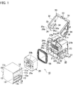
FIG. 1 is an exploded perspective view illustrating an example of a lever-type connector according to the present embodiment; -
FIG. 2 is a side view of a male housing of the lever-type connector; -
FIG. 3 is a side view of a female housing of the lever-type connector; -
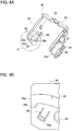
FIG. 4A is a perspective view of a lever of the lever-type connector; -
FIG. 4B is an enlarged side view of a part A inFIG. 4A ; -
FIG. 5 is a perspective view illustrating a state before the male housing and the female housing are temporarily set; -
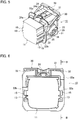
FIG. 6 is a front view of the lever-type connector before the temporary setting; -
FIG. 7 is a sectional view taken along a line B-B inFIG. 6 ; -
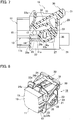
FIG. 8 is a perspective view illustrating a state after the male housing and the female housing are temporarily set; and -
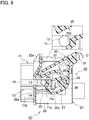
FIG. 9 is a sectional view taken along the line B-B inFIG. 6 , illustrating the state after the male housing and the female housing are temporarily set. - Hereinafter, a lever-type connector according to the present embodiment will be described in detail with reference to the drawings. Note that the dimensional ratios in the drawings are exaggerated for convenience of explanation, and may differ from the actual ratios.
- As illustrated in
FIG. 1 , a lever-type connector 10 includes a male housing (mating housing) 11 that is made of synthetic resin and has acam boss 12, a female housing (housing) 20 that is made of synthetic resin and is fitted into and removed from themale housing 11, and alever 30 made of synthetic resin. Thelever 30 is rotatably supported by asupport shaft 23 arranged in thefemale housing 20, and has acam groove 35 that engages with thecam boss 12 of themale housing 11. By rotating anoperating portion 31 of thelever 30, thecam groove 35 is engaged with thecam boss 12 and thus themale housing 11 is made to move toward thefemale housing 20, so that themale housing 11 and thefemale housing 20 are fitted to each other. InFIG. 1 , the direction in which themale housing 11 and thefemale housing 20 are fitted to each other is referred to as "fitting direction", the direction orthogonal to the fitting direction, in which thecam bosses 12 formed on bothside surfaces male housing 11 are connected, is referred to as "width direction", and the vertical direction in the figure orthogonal to the fitting direction and the width direction, in which anupper surface 21c and a bottom surface of thefemale housing 20 are connected, is referred to as "height direction". Note that the directions such as "longitudinal" and "vertical" are defined for convenience of explanation, and do not limit the actual mounting orientations of the respective elements. - As illustrated in
FIGS. 1 and2 , themale housing 11 has, on the front side (one fitting-direction side), ahood portion 11a that is inserted into ahood portion 22 of thefemale housing 20. Thecylindrical cam boss 12 is integrally formed in a projecting manner at a center in the height direction of each of theside surfaces male housing 11 in the width direction. Arelease rib portion 13 extending in the longitudinal direction (fitting direction) is integrally formed in a projecting manner under (on one height-direction side of) thecam boss 12 on each of theside surfaces male housing 11. Adistal end 13a of therelease rib portion 13 on one fitting-direction side functions as a release portion that releases a temporary locking state of a cutaway portion (temporarily locked portion) 25 of thefemale housing 20 and a temporary locking projection (temporary locking portion) 36a of a temporarylocking arm portion 36 of thelever 30, which will be described later. A trapezoidal temporaryset beak portion 14 is integrally formed in a projecting manner at a center in the fitting direction of alower surface 13c of therelease rib portion 13 in the height direction. As illustrated inFIG. 2 , aslope 13b is formed on the back side (other fitting-direction side) of thedistal end 13a of therelease rib portion 13. The trapezoidal temporaryset beak portion 14 has afront slope 14a on one fitting-direction side, astraight surface 14b, and aback slope 14c on the other fitting-direction side. In thehood portion 11a of themale housing 11, a tab portion of a male terminal (terminal), which is not illustrated, is exposed. - As illustrated in
FIG. 1 , thefemale housing 20 includes a block-like housingmain body 21 having a plurality ofterminal accommodating chambers 21a, and thehood portion 22 that is integrally formed in a projecting manner on the front side (other fitting-direction side) of the housingmain body 21 and into which thehood portion 11a of themale housing 11 is fitted. Thesupport shaft 23 is integrally formed in a projecting manner at a center in the height direction of each ofside surfaces main body 21 in the width direction. An elastically deformablelocking arm portion 24 is integrally formed in a projecting manner on the front side (other fitting-direction side) at a center in the width direction of theupper surface 21c of the housingmain body 21 in the height direction. A receivingportion 24b is integrally formed in a projecting manner at a free end (distal end) 24a of thelocking arm portion 24. - As illustrated in
FIGS. 1 and3 , the substantially rectangular cutaway portion (temporarily locked portion) 25 is formed on the front side (other fitting-direction side) at a center in the height direction of each of side portions of thehood portion 22 of thefemale housing 20 in the width direction. That is, thetemporary locking projection 36a of the temporarylocking arm portion 36 of thelever 30 to be described later is temporarily locked to or unlocked from alower edge 25a of eachcutaway portion 25 in the height direction. When thetemporary locking projection 36a of the temporarylocking arm portion 36 is temporarily locked to thelower edge 25a of thecutaway portion 25, thelever 30 is held at a temporary lock position. - As illustrated in
FIGS. 1 and3 , a double-supported temporaryset arm portion 26 is integrally formed to be elastically deformable on the front side (other fitting-direction side) of thelower edge 25a of eachcutaway portion 25. Aprojection 26a is formed on an upper surface (other height-direction side) closer to the front side (other fitting-direction side) of the temporaryset arm portion 26. Theprojection 26a slides along thelower surface 13c of therelease rib portion 13. The temporaryset arm portion 26 functions to prevent themale housing 11 from being removed from thefemale housing 20, themale housing 11 and thefemale housing 20 being in a temporary set state when thelever 30 is unlocked from the temporary locking position, until theprojection 26a slides along thelower surface 13c of therelease rib portion 13 and reaches a position across the temporaryset beak portion 14. - As illustrated in
FIG. 1 , a rectangularcylindrical front holder 29 that is made of synthetic resin and has afront wall portion 29a is fitted to the periphery of a plurality of theterminal accommodating chambers 21a of the housingmain body 21 in thehood portion 22 of thefemale housing 20. A rectangularannular packing 28 made of rubber is interposed between thehood portion 22 of thefemale housing 20 and the periphery of theterminal accommodating chambers 21 a of the housingmain body 21. Thefront wall portion 29a of thefront holder 29 includes a plurality ofrectangular openings 29b communicating with the plurality ofterminal accommodating chambers 21a of the housingmain body 21. A female terminal (not illustrated) is accommodated in theterminal accommodating chamber 21a of the housingmain body 21. The female terminal accommodated in theterminal accommodating chamber 21a of the housingmain body 21 is held by a lance (not illustrated) arranged in theterminal accommodating chamber 21a. - As illustrated in
FIGS. 1 and4A , thelever 30 includes the operatingportion 31 and a pair ofarm portions portion 31 in the width direction. - As illustrated in
FIGS. 1 and4A , a lockingprojection 33 is formed on the lower side (one height-direction side) at a center in the width direction of the operatingportion 31 of thelever 30. When thelever 30 is rotated to a rotation completion position, the lockingprojection 33 is locked to the receivingportion 24b of thelocking arm portion 24 in thefemale housing 20. This locking brings about a rotation restricting state where the rotation of thelever 30 is restricted. The lock state of the lockingprojection 33 of thelever 30 and the receivingportion 24b of thelocking arm portion 24 in thefemale housing 20 is released by pressing the side of thefree end 24a of thelocking arm portion 24 downward (one height-direction side) so as to detach the receivingportion 24b of thelocking arm portion 24 from the lockingprojection 33. - As illustrated in
FIGS. 1 and4A , a bearinghole 34 that is rotatably supported by thesupport shaft 23 is formed on the back side (one fitting-direction side) of eacharm portion 32 of thelever 30. The arcuate recessedcam groove 35 is formed in each of the inner sides of the arm portions 32 (sides at whicharm portions 32 face to each other in width direction). The temporarylocking arm portion 36 that is elastically deformable and has the temporary locking projection (temporary locking portion) 36a at its distal end is integrally formed on each of the lower sides (one height-direction side) of thearm portions 32. The temporary locking state of thetemporary locking projection 36a of the temporarylocking arm portion 36 in thelever 30 and thelower edge 25a of thecutaway portion 25 in thefemale housing 20 is released by thedistal end 13a of therelease rib portion 13 in themale housing 11. It is configured that immediately after the temporary locking state is released by thedistal end 13a (after temporary locking state is released or at the same time when temporary locking state is released), theprojection 26a of the temporaryset arm portion 26 in thefemale housing 20 is moved across the temporaryset beak portion 14 of therelease rib portion 13 in themale housing 11. That is, at the position where theprojection 26a of the temporaryset arm portion 26 in thefemale housing 20 is moved across theback slope 14c of the temporaryset beak portion 14 in themale housing 11 to abut against thelower surface 13c of therelease rib portion 13, the temporary locking state of thetemporary locking projection 36a of the temporarylocking arm portion 36 in thelever 30 and thelower edge 25a of thecutaway portion 25 in thefemale housing 20 is completely released by thedistal end 13a of therelease rib portion 13 in themale housing 11. - As illustrated in
FIGS. 4A, 4B ,7 , and9 , thecam groove 35 of thearm portion 32 in thelever 30 includes aboss receiving portion 35b that receives thecam boss 12 of themale housing 11. Theboss receiving portion 35b is formed by cutting, in an L shape, the lower side (one height-direction side) of thecam groove 35 closer to anentrance 35a of thecam boss 12. Theboss receiving portion 35b functions when the temporary locking state of thetemporary locking projection 36a of the temporarylocking arm portion 36 and thecutaway portion 25 of thefemale housing 20 is released in a state where themale housing 11 and thefemale housing 20 are temporarily set. - As illustrated in
FIGS. 1 and6 , aprotrusion 15 parallel to therelease rib portion 13 in the fitting direction is integrally formed in a projecting manner on the back side (on other fitting-direction side of) of thecam boss 12 on each of the side surfaces 11b, 11b of themale housing 11. As illustrated inFIG. 5 , when themale housing 11 is inserted into thehood portion 22 of thefemale housing 20, theprotrusion 15 of themale housing 11 is accommodated and guided in arecess 22b on each of both sides of aflange portion 22a of thehood portion 22 in thefemale housing 20. When thelever 30 is rotated from a temporary locking position to a rotation completion position, the lockingprojection 33 of thelever 30 is locked to the receivingportion 24b of thelocking arm portion 24 in thefemale housing 20 and maintained in a rotation restricting state. At this time, thetemporary locking projection 36a of the temporarylocking arm portion 36 formed on thearm portion 32 of thelever 30 is moved to ahole 27 formed from thelower edge 25a of thecutaway portion 25 made on each of both sides of thehood portion 22 in thefemale housing 20 downward (toward one height-direction side) of thecutaway portion 25, and then is accommodated in thehole 27. - As described above, according to the lever-
type connector 10 of the embodiment, as illustrated inFIGS. 5 to 7 , when thehood portion 11a of themale housing 11 is pushed into thehood portion 22 of thefemale housing 20, thedistal end 13a of therelease rib portion 13 in themale housing 11 abuts against thetemporary locking projection 36a of the temporarylocking arm portion 36 of thelever 30. Immediately before this abutment, thecam boss 12 of themale housing 11 enters thecam groove 35 of thelever 30. - Thereafter, as illustrated in
FIG. 9 , thecam boss 12 of themale housing 11 abuts against theboss receiving portion 35b of thecam groove 35 of thelever 30. As a result, even if thehood portion 11 a of themale housing 11 is pushed further into thehood portion 22 of thefemale housing 20, the rotation of the operatingportion 31 of thelever 30 in a direction of an arrow C is prevented (force vector is prevented from tilting whenfood portion 11a is pushed further into food portion 22). Consequently, the position of thelever 30 when themale housing 11 and thefemale housing 20 are temporarily set is restricted. Since theboss receiving portion 35b that receives thecam boss 12 of themale housing 11 is formed in thecam groove 35 of thelever 30 as described above, it is possible to prevent thelever 30 from rotating in the direction of the arrow C when themale housing 11 and thefemale housing 20 are temporarily set. Further, before the operatingportion 31 of thelever 30 is operated, it is possible to reliably prevent electrical conduction between terminals of themale housing 11 and thefemale housing 20 in a state where themale housing 11 and thefemale housing 20 are temporarily set. - In addition, as illustrated in
FIG. 9 , when thecam boss 12 of themale housing 11 abuts against theboss receiving portion 35b of thecam groove 35 of thelever 30, thedistal end 13a of therelease rib portion 13 of themale housing 11 abuts against the temporarylocking arm portion 36 of thelever 30 and pushes the temporarylocking arm portion 36 upward. As a result, the temporary locking state of thecutaway portion 25 of thefemale housing 20 and thetemporary locking projection 36a of the temporarylocking arm portion 36 of thelever 30 starts to be released. Since thecam boss 12 of themale housing 11 is received by theboss receiving portion 35b of thecam groove 35 of thelever 30 as described above, the same structure makes it possible to temporarily set themale housing 11 and thefemale housing 20, and release the temporary locking state of the temporarylocking arm portion 36 of thelever 30. - When the operating
portion 31 of thelever 30 is rotated, thecam groove 35 of thearm portion 32 of thelever 30 engages with thecam boss 12 of themale housing 11 and thus themale housing 11 is made to move toward thefemale housing 20, so that themale housing 11 and thefemale housing 20 are fitted to each other. When thelever 30 is completely rotated, the lockingprojection 33 on the lower side of the operatingportion 31 of thelever 30 is locked to the receivingportion 24b of thelocking arm portion 24 in thefemale housing 20, which brings about the rotation restricting state where the rotation of thelever 30 is restricted. - While the present embodiment has been described above, the present embodiment is not limited thereto, and various modifications can be made within the scope of the gist of the present embodiment.
- That is, according to the embodiment described above, the cutaway portion of the female housing functioning as a temporarily locked portion and the temporary locking projection of the temporary locking arm portion of the lever functioning as a temporary locking portion are temporarily locked to each other, however, the temporarily locked portion may be a recess, a protrusion, or the like besides the cutaway portion.
- Next, a comparative example will be described. A lever-type connector 1 according to the comparative example includes a housing 2 having a fitting cylindrical portion 2a that is fitted into and removed from a hood portion 7a of a mating housing 7. In addition, the lever-type connector 1 includes a lever 4. The lever 4 is rotatably supported, via bearings 5, by support shafts 3 on both sides of the fitting cylindrical portion 2a of the housing 2, and has a cam groove 6 that engages with a cam follower 8 arranged in the hood portion 7a of the mating housing 7. By rotating an operating portion 4a, the cam groove 6 is engaged with the cam follower 8 and thus the housings 2 and 7 are fitted to each other.
- The shaft center of the cam follower 8 in the mating housing 7, the cam follower 8 being engaged with the cam groove 6 of the lever 4, is shifted in position toward the operating portion 4a, which is upward of the shaft center of the bearing 5 of the lever 4 in a vertical direction (direction orthogonal to fitting direction of housing 2 and mating housing 7). For this reason, when the housings 2 and 7 are properly fitted, a terminal end portion 6a of the cam groove 6 that receives the cam follower 8 is located closer to the operating portion 4a than the bearing 5. Compared to a case where the terminal end portion 6a and the bearing 5 are located at the same height, the amount that the cam groove 6 extends to the side of the bearing 5 opposite to the side of the bearing 5 closer to the operating portion 4a (lower side) can be reduced, and thus it is possible to prevent the lever 4 from becoming large in the vertical direction.
- However, in the lever-type connector 1 according to the comparative example, the cam follower 8 of the mating housing 7 abuts against a gentle slope of the cam groove 6 of the lever 4. For this reason, when the mating housing 7 is pushed further into the housing 2 from a temporarily set state of the housings 2 and 7, the lever 4 may rotate, and a female terminal 2A of the housing 2 and a male terminal 9 of the mating housing 7 may be fitted into a position where these terminals 2A and 9 can be electrically conducted.
- Although the present invention has been described above by reference to the embodiment, the present invention is not limited to those and the configuration of parts can be replaced with any configuration having a similar function, as long as they lie within the scope of the claims.
Claims (2)
- A lever-type connector comprising:a mating housing having a cam boss;a housing that is fitted into and removed from the mating housing; anda lever that is rotatably supported by the housing via a support shaft, has a cam groove engaging with the cam boss, and is rotated from a temporary locking position to cause the cam groove to engage with the cam boss, thus moving the mating housing toward the housing and fitting the mating housing and the housing to each other, whereinthe lever includes a temporary locking arm portion that has a temporary locking portion and is elastically deformable,the housing includes a temporarily locked portion that is temporarily locked to and unlocked from the temporary locking portion of the temporary locking arm portion,the mating housing includes a release rib portion that releases a temporary locking state of the temporary locking portion of the temporary locking arm portion and the temporarily locked portion of the housing, andthe cam groove of the lever includes a boss receiving portion that receives the cam boss when the temporary locking state of the temporary locking portion of the temporary locking arm portion and the temporarily locked portion of the housing is released in a state where the mating housing and the housing are temporarily set.
- The lever-type connector according to claim 1, whereina projecting temporary set beak portion is formed on a lower surface of the release rib portion,the housing includes a temporary set arm portion that prevents the mating housing from being removed from the housing, the mating housing and the housing being in a temporary set state when a temporary locking state of the temporary locking portion of the temporary locking arm portion of the lever and the temporarily locked portion of the housing is released,a distal end of the temporary set arm portion includes a projection that slides along the lower surface of the release rib portion, andthe temporary locking state of the temporary locking portion of the temporary locking arm portion of the lever and the temporarily locked portion of the housing is released at a position where the projection is across the temporary set beak portion from the lower surface of the release rib portion.
Applications Claiming Priority (1)
| Application Number | Priority Date | Filing Date | Title |
|---|---|---|---|
| JP2019129747A JP7065057B2 (en) | 2019-07-12 | 2019-07-12 | Lever type connector |
Publications (2)
| Publication Number | Publication Date |
|---|---|
| EP3764480A1 true EP3764480A1 (en) | 2021-01-13 |
| EP3764480B1 EP3764480B1 (en) | 2022-11-23 |
Family
ID=71451985
Family Applications (1)
| Application Number | Title | Priority Date | Filing Date |
|---|---|---|---|
| EP20183441.3A Active EP3764480B1 (en) | 2019-07-12 | 2020-07-01 | Lever-type connector |
Country Status (4)
| Country | Link |
|---|---|
| US (1) | US11251566B2 (en) |
| EP (1) | EP3764480B1 (en) |
| JP (1) | JP7065057B2 (en) |
| CN (1) | CN112290292B (en) |
Families Citing this family (8)
| Publication number | Priority date | Publication date | Assignee | Title |
|---|---|---|---|---|
| KR102829875B1 (en) * | 2020-12-28 | 2025-07-03 | 현대자동차주식회사 | Connector assembly |
| CN114256693B (en) * | 2021-11-29 | 2023-12-19 | 中航光电科技股份有限公司 | A high-speed ultra-fine coaxial connector elastic hook locking structure |
| KR102658616B1 (en) * | 2021-12-06 | 2024-04-18 | 주식회사 유라 | Connector |
| KR102666878B1 (en) * | 2021-12-06 | 2024-05-17 | 주식회사 유라 | Connector |
| KR102928254B1 (en) | 2022-10-31 | 2026-02-19 | 주식회사 유라 | Female Connector |
| JP2024073262A (en) * | 2022-11-17 | 2024-05-29 | 日本航空電子工業株式会社 | Connector device |
| JP2024120467A (en) * | 2023-02-24 | 2024-09-05 | 住友電装株式会社 | connector |
| EP4468531A1 (en) * | 2023-05-26 | 2024-11-27 | TE Connectivity India Private Limited | Housing assembly for a connector, connector and connection assembly |
Citations (3)
| Publication number | Priority date | Publication date | Assignee | Title |
|---|---|---|---|---|
| EP0727846A1 (en) * | 1993-11-05 | 1996-08-21 | SUMITOMO WIRING SYSTEMS, Ltd. | Lever type connector |
| JP2017168391A (en) | 2016-03-18 | 2017-09-21 | 住友電装株式会社 | Lever type connector |
| DE102017208784A1 (en) * | 2016-05-30 | 2017-11-30 | Yazaki Corporation | Connectors |
Family Cites Families (5)
| Publication number | Priority date | Publication date | Assignee | Title |
|---|---|---|---|---|
| JPH0611272U (en) * | 1992-07-13 | 1994-02-10 | 住友電装株式会社 | Lever type connector |
| JP3758525B2 (en) * | 2001-05-24 | 2006-03-22 | 住友電装株式会社 | Lever type connector |
| JP2003100382A (en) | 2001-09-25 | 2003-04-04 | Yazaki Corp | Lever fitting type power supply circuit breaker |
| KR200318480Y1 (en) | 2003-04-02 | 2003-06-27 | 한국몰렉스 주식회사 | A locking structure of a connector assembly for cars |
| JP2016126841A (en) | 2014-12-26 | 2016-07-11 | 住友電装株式会社 | Lever type connector |
-
2019
- 2019-07-12 JP JP2019129747A patent/JP7065057B2/en active Active
-
2020
- 2020-07-01 EP EP20183441.3A patent/EP3764480B1/en active Active
- 2020-07-10 US US16/925,721 patent/US11251566B2/en active Active
- 2020-07-10 CN CN202010662101.0A patent/CN112290292B/en active Active
Patent Citations (3)
| Publication number | Priority date | Publication date | Assignee | Title |
|---|---|---|---|---|
| EP0727846A1 (en) * | 1993-11-05 | 1996-08-21 | SUMITOMO WIRING SYSTEMS, Ltd. | Lever type connector |
| JP2017168391A (en) | 2016-03-18 | 2017-09-21 | 住友電装株式会社 | Lever type connector |
| DE102017208784A1 (en) * | 2016-05-30 | 2017-11-30 | Yazaki Corporation | Connectors |
Also Published As
| Publication number | Publication date |
|---|---|
| JP2021015719A (en) | 2021-02-12 |
| JP7065057B2 (en) | 2022-05-11 |
| EP3764480B1 (en) | 2022-11-23 |
| US20210013675A1 (en) | 2021-01-14 |
| CN112290292A (en) | 2021-01-29 |
| US11251566B2 (en) | 2022-02-15 |
| CN112290292B (en) | 2022-05-31 |
Similar Documents
| Publication | Publication Date | Title |
|---|---|---|
| EP3764480B1 (en) | Lever-type connector | |
| EP3764482B1 (en) | Lever-type connector | |
| US9871322B2 (en) | Connector | |
| US10644430B2 (en) | Connector and connector structure | |
| EP1734619A1 (en) | A connector and connector assembly of the movable member type | |
| US8215970B2 (en) | Connector | |
| US9831602B1 (en) | Connector | |
| US8998626B2 (en) | Connector and connector assembly | |
| CN107959154A (en) | Connector | |
| CN114976744A (en) | Cable connector | |
| US6623286B2 (en) | Lever-type connector | |
| EP0660451B1 (en) | Connector | |
| CN111697392B (en) | Lever Connector | |
| EP1094559B1 (en) | Electrical connector having a terminal retainer | |
| EP3734770B1 (en) | Electrical connector having position holder | |
| US20100015827A1 (en) | Connector | |
| US20030177620A1 (en) | Lever-type connector and connector assembly | |
| CN113557641B (en) | Connector position assurance component | |
| JP5737213B2 (en) | Lever type connector | |
| EP3817155B1 (en) | Lever-type connector | |
| EP0992083B1 (en) | Electrical connector having a secondary locking member | |
| EP4550585A1 (en) | Electrical connector assembly | |
| US20200335897A1 (en) | Grommet-equipped connector | |
| JP2000195617A (en) | Connector |
Legal Events
| Date | Code | Title | Description |
|---|---|---|---|
| PUAI | Public reference made under article 153(3) epc to a published international application that has entered the european phase |
Free format text: ORIGINAL CODE: 0009012 |
|
| STAA | Information on the status of an ep patent application or granted ep patent |
Free format text: STATUS: REQUEST FOR EXAMINATION WAS MADE |
|
| 17P | Request for examination filed |
Effective date: 20200701 |
|
| AK | Designated contracting states |
Kind code of ref document: A1 Designated state(s): AL AT BE BG CH CY CZ DE DK EE ES FI FR GB GR HR HU IE IS IT LI LT LU LV MC MK MT NL NO PL PT RO RS SE SI SK SM TR |
|
| AX | Request for extension of the european patent |
Extension state: BA ME |
|
| RBV | Designated contracting states (corrected) |
Designated state(s): AL AT BE BG CH CY CZ DE DK EE ES FI FR GB GR HR HU IE IS IT LI LT LU LV MC MK MT NL NO PL PT RO RS SE SI SK SM TR |
|
| STAA | Information on the status of an ep patent application or granted ep patent |
Free format text: STATUS: EXAMINATION IS IN PROGRESS |
|
| 17Q | First examination report despatched |
Effective date: 20210928 |
|
| GRAP | Despatch of communication of intention to grant a patent |
Free format text: ORIGINAL CODE: EPIDOSNIGR1 |
|
| STAA | Information on the status of an ep patent application or granted ep patent |
Free format text: STATUS: GRANT OF PATENT IS INTENDED |
|
| RIC1 | Information provided on ipc code assigned before grant |
Ipc: H01R 13/627 20060101ALN20220902BHEP Ipc: H01R 13/629 20060101AFI20220902BHEP |
|
| GRAS | Grant fee paid |
Free format text: ORIGINAL CODE: EPIDOSNIGR3 |
|
| RIC1 | Information provided on ipc code assigned before grant |
Ipc: H01R 13/627 20060101ALN20220912BHEP Ipc: H01R 13/629 20060101AFI20220912BHEP |
|
| GRAA | (expected) grant |
Free format text: ORIGINAL CODE: 0009210 |
|
| STAA | Information on the status of an ep patent application or granted ep patent |
Free format text: STATUS: THE PATENT HAS BEEN GRANTED |
|
| INTG | Intention to grant announced |
Effective date: 20220928 |
|
| RIC1 | Information provided on ipc code assigned before grant |
Ipc: H01R 13/627 20060101ALN20220916BHEP Ipc: H01R 13/629 20060101AFI20220916BHEP |
|
| AK | Designated contracting states |
Kind code of ref document: B1 Designated state(s): AL AT BE BG CH CY CZ DE DK EE ES FI FR GB GR HR HU IE IS IT LI LT LU LV MC MK MT NL NO PL PT RO RS SE SI SK SM TR |
|
| REG | Reference to a national code |
Ref country code: GB Ref legal event code: FG4D |
|
| REG | Reference to a national code |
Ref country code: CH Ref legal event code: EP |
|
| REG | Reference to a national code |
Ref country code: AT Ref legal event code: REF Ref document number: 1533728 Country of ref document: AT Kind code of ref document: T Effective date: 20221215 Ref country code: DE Ref legal event code: R096 Ref document number: 602020006418 Country of ref document: DE |
|
| REG | Reference to a national code |
Ref country code: IE Ref legal event code: FG4D |
|
| REG | Reference to a national code |
Ref country code: LT Ref legal event code: MG9D |
|
| REG | Reference to a national code |
Ref country code: NL Ref legal event code: MP Effective date: 20221123 |
|
| REG | Reference to a national code |
Ref country code: AT Ref legal event code: MK05 Ref document number: 1533728 Country of ref document: AT Kind code of ref document: T Effective date: 20221123 |
|
| PG25 | Lapsed in a contracting state [announced via postgrant information from national office to epo] |
Ref country code: SE Free format text: LAPSE BECAUSE OF FAILURE TO SUBMIT A TRANSLATION OF THE DESCRIPTION OR TO PAY THE FEE WITHIN THE PRESCRIBED TIME-LIMIT Effective date: 20221123 Ref country code: PT Free format text: LAPSE BECAUSE OF FAILURE TO SUBMIT A TRANSLATION OF THE DESCRIPTION OR TO PAY THE FEE WITHIN THE PRESCRIBED TIME-LIMIT Effective date: 20230323 Ref country code: NO Free format text: LAPSE BECAUSE OF FAILURE TO SUBMIT A TRANSLATION OF THE DESCRIPTION OR TO PAY THE FEE WITHIN THE PRESCRIBED TIME-LIMIT Effective date: 20230223 Ref country code: LT Free format text: LAPSE BECAUSE OF FAILURE TO SUBMIT A TRANSLATION OF THE DESCRIPTION OR TO PAY THE FEE WITHIN THE PRESCRIBED TIME-LIMIT Effective date: 20221123 Ref country code: FI Free format text: LAPSE BECAUSE OF FAILURE TO SUBMIT A TRANSLATION OF THE DESCRIPTION OR TO PAY THE FEE WITHIN THE PRESCRIBED TIME-LIMIT Effective date: 20221123 Ref country code: ES Free format text: LAPSE BECAUSE OF FAILURE TO SUBMIT A TRANSLATION OF THE DESCRIPTION OR TO PAY THE FEE WITHIN THE PRESCRIBED TIME-LIMIT Effective date: 20221123 Ref country code: AT Free format text: LAPSE BECAUSE OF FAILURE TO SUBMIT A TRANSLATION OF THE DESCRIPTION OR TO PAY THE FEE WITHIN THE PRESCRIBED TIME-LIMIT Effective date: 20221123 |
|
| PG25 | Lapsed in a contracting state [announced via postgrant information from national office to epo] |
Ref country code: RS Free format text: LAPSE BECAUSE OF FAILURE TO SUBMIT A TRANSLATION OF THE DESCRIPTION OR TO PAY THE FEE WITHIN THE PRESCRIBED TIME-LIMIT Effective date: 20221123 Ref country code: PL Free format text: LAPSE BECAUSE OF FAILURE TO SUBMIT A TRANSLATION OF THE DESCRIPTION OR TO PAY THE FEE WITHIN THE PRESCRIBED TIME-LIMIT Effective date: 20221123 Ref country code: LV Free format text: LAPSE BECAUSE OF FAILURE TO SUBMIT A TRANSLATION OF THE DESCRIPTION OR TO PAY THE FEE WITHIN THE PRESCRIBED TIME-LIMIT Effective date: 20221123 Ref country code: IS Free format text: LAPSE BECAUSE OF FAILURE TO SUBMIT A TRANSLATION OF THE DESCRIPTION OR TO PAY THE FEE WITHIN THE PRESCRIBED TIME-LIMIT Effective date: 20230323 Ref country code: HR Free format text: LAPSE BECAUSE OF FAILURE TO SUBMIT A TRANSLATION OF THE DESCRIPTION OR TO PAY THE FEE WITHIN THE PRESCRIBED TIME-LIMIT Effective date: 20221123 Ref country code: GR Free format text: LAPSE BECAUSE OF FAILURE TO SUBMIT A TRANSLATION OF THE DESCRIPTION OR TO PAY THE FEE WITHIN THE PRESCRIBED TIME-LIMIT Effective date: 20230224 |
|
| RAP4 | Party data changed (patent owner data changed or rights of a patent transferred) |
Owner name: YAZAKI CORPORATION |
|
| PG25 | Lapsed in a contracting state [announced via postgrant information from national office to epo] |
Ref country code: NL Free format text: LAPSE BECAUSE OF FAILURE TO SUBMIT A TRANSLATION OF THE DESCRIPTION OR TO PAY THE FEE WITHIN THE PRESCRIBED TIME-LIMIT Effective date: 20221123 |
|
| PG25 | Lapsed in a contracting state [announced via postgrant information from national office to epo] |
Ref country code: SM Free format text: LAPSE BECAUSE OF FAILURE TO SUBMIT A TRANSLATION OF THE DESCRIPTION OR TO PAY THE FEE WITHIN THE PRESCRIBED TIME-LIMIT Effective date: 20221123 Ref country code: RO Free format text: LAPSE BECAUSE OF FAILURE TO SUBMIT A TRANSLATION OF THE DESCRIPTION OR TO PAY THE FEE WITHIN THE PRESCRIBED TIME-LIMIT Effective date: 20221123 Ref country code: EE Free format text: LAPSE BECAUSE OF FAILURE TO SUBMIT A TRANSLATION OF THE DESCRIPTION OR TO PAY THE FEE WITHIN THE PRESCRIBED TIME-LIMIT Effective date: 20221123 Ref country code: DK Free format text: LAPSE BECAUSE OF FAILURE TO SUBMIT A TRANSLATION OF THE DESCRIPTION OR TO PAY THE FEE WITHIN THE PRESCRIBED TIME-LIMIT Effective date: 20221123 Ref country code: CZ Free format text: LAPSE BECAUSE OF FAILURE TO SUBMIT A TRANSLATION OF THE DESCRIPTION OR TO PAY THE FEE WITHIN THE PRESCRIBED TIME-LIMIT Effective date: 20221123 |
|
| REG | Reference to a national code |
Ref country code: DE Ref legal event code: R097 Ref document number: 602020006418 Country of ref document: DE |
|
| PG25 | Lapsed in a contracting state [announced via postgrant information from national office to epo] |
Ref country code: SK Free format text: LAPSE BECAUSE OF FAILURE TO SUBMIT A TRANSLATION OF THE DESCRIPTION OR TO PAY THE FEE WITHIN THE PRESCRIBED TIME-LIMIT Effective date: 20221123 Ref country code: AL Free format text: LAPSE BECAUSE OF FAILURE TO SUBMIT A TRANSLATION OF THE DESCRIPTION OR TO PAY THE FEE WITHIN THE PRESCRIBED TIME-LIMIT Effective date: 20221123 |
|
| PLBE | No opposition filed within time limit |
Free format text: ORIGINAL CODE: 0009261 |
|
| STAA | Information on the status of an ep patent application or granted ep patent |
Free format text: STATUS: NO OPPOSITION FILED WITHIN TIME LIMIT |
|
| 26N | No opposition filed |
Effective date: 20230824 |
|
| PG25 | Lapsed in a contracting state [announced via postgrant information from national office to epo] |
Ref country code: SI Free format text: LAPSE BECAUSE OF FAILURE TO SUBMIT A TRANSLATION OF THE DESCRIPTION OR TO PAY THE FEE WITHIN THE PRESCRIBED TIME-LIMIT Effective date: 20221123 |
|
| PG25 | Lapsed in a contracting state [announced via postgrant information from national office to epo] |
Ref country code: MC Free format text: LAPSE BECAUSE OF FAILURE TO SUBMIT A TRANSLATION OF THE DESCRIPTION OR TO PAY THE FEE WITHIN THE PRESCRIBED TIME-LIMIT Effective date: 20221123 |
|
| PG25 | Lapsed in a contracting state [announced via postgrant information from national office to epo] |
Ref country code: MC Free format text: LAPSE BECAUSE OF FAILURE TO SUBMIT A TRANSLATION OF THE DESCRIPTION OR TO PAY THE FEE WITHIN THE PRESCRIBED TIME-LIMIT Effective date: 20221123 |
|
| REG | Reference to a national code |
Ref country code: CH Ref legal event code: PL |
|
| REG | Reference to a national code |
Ref country code: BE Ref legal event code: MM Effective date: 20230731 |
|
| PG25 | Lapsed in a contracting state [announced via postgrant information from national office to epo] |
Ref country code: LU Free format text: LAPSE BECAUSE OF NON-PAYMENT OF DUE FEES Effective date: 20230701 |
|
| PG25 | Lapsed in a contracting state [announced via postgrant information from national office to epo] |
Ref country code: LU Free format text: LAPSE BECAUSE OF NON-PAYMENT OF DUE FEES Effective date: 20230701 |
|
| REG | Reference to a national code |
Ref country code: IE Ref legal event code: MM4A |
|
| PG25 | Lapsed in a contracting state [announced via postgrant information from national office to epo] |
Ref country code: CH Free format text: LAPSE BECAUSE OF NON-PAYMENT OF DUE FEES Effective date: 20230731 |
|
| PG25 | Lapsed in a contracting state [announced via postgrant information from national office to epo] |
Ref country code: IT Free format text: LAPSE BECAUSE OF FAILURE TO SUBMIT A TRANSLATION OF THE DESCRIPTION OR TO PAY THE FEE WITHIN THE PRESCRIBED TIME-LIMIT Effective date: 20221123 Ref country code: FR Free format text: LAPSE BECAUSE OF NON-PAYMENT OF DUE FEES Effective date: 20230731 Ref country code: BE Free format text: LAPSE BECAUSE OF NON-PAYMENT OF DUE FEES Effective date: 20230731 |
|
| PG25 | Lapsed in a contracting state [announced via postgrant information from national office to epo] |
Ref country code: IE Free format text: LAPSE BECAUSE OF NON-PAYMENT OF DUE FEES Effective date: 20230701 |
|
| PG25 | Lapsed in a contracting state [announced via postgrant information from national office to epo] |
Ref country code: IE Free format text: LAPSE BECAUSE OF NON-PAYMENT OF DUE FEES Effective date: 20230701 |
|
| PG25 | Lapsed in a contracting state [announced via postgrant information from national office to epo] |
Ref country code: BG Free format text: LAPSE BECAUSE OF FAILURE TO SUBMIT A TRANSLATION OF THE DESCRIPTION OR TO PAY THE FEE WITHIN THE PRESCRIBED TIME-LIMIT Effective date: 20221123 |
|
| PG25 | Lapsed in a contracting state [announced via postgrant information from national office to epo] |
Ref country code: BG Free format text: LAPSE BECAUSE OF FAILURE TO SUBMIT A TRANSLATION OF THE DESCRIPTION OR TO PAY THE FEE WITHIN THE PRESCRIBED TIME-LIMIT Effective date: 20221123 |
|
| GBPC | Gb: european patent ceased through non-payment of renewal fee |
Effective date: 20240701 |
|
| PG25 | Lapsed in a contracting state [announced via postgrant information from national office to epo] |
Ref country code: GB Free format text: LAPSE BECAUSE OF NON-PAYMENT OF DUE FEES Effective date: 20240701 |
|
| PG25 | Lapsed in a contracting state [announced via postgrant information from national office to epo] |
Ref country code: CY Free format text: LAPSE BECAUSE OF FAILURE TO SUBMIT A TRANSLATION OF THE DESCRIPTION OR TO PAY THE FEE WITHIN THE PRESCRIBED TIME-LIMIT; INVALID AB INITIO Effective date: 20200701 |
|
| PG25 | Lapsed in a contracting state [announced via postgrant information from national office to epo] |
Ref country code: HU Free format text: LAPSE BECAUSE OF FAILURE TO SUBMIT A TRANSLATION OF THE DESCRIPTION OR TO PAY THE FEE WITHIN THE PRESCRIBED TIME-LIMIT; INVALID AB INITIO Effective date: 20200701 |
|
| PGFP | Annual fee paid to national office [announced via postgrant information from national office to epo] |
Ref country code: DE Payment date: 20250528 Year of fee payment: 6 |
|
| PG25 | Lapsed in a contracting state [announced via postgrant information from national office to epo] |
Ref country code: TR Free format text: LAPSE BECAUSE OF FAILURE TO SUBMIT A TRANSLATION OF THE DESCRIPTION OR TO PAY THE FEE WITHIN THE PRESCRIBED TIME-LIMIT Effective date: 20221123 |