EP3764430A1 - Apparatus for manufacturing battery and method for manufacturing battery by using same - Google Patents
Apparatus for manufacturing battery and method for manufacturing battery by using same Download PDFInfo
- Publication number
- EP3764430A1 EP3764430A1 EP19888148.4A EP19888148A EP3764430A1 EP 3764430 A1 EP3764430 A1 EP 3764430A1 EP 19888148 A EP19888148 A EP 19888148A EP 3764430 A1 EP3764430 A1 EP 3764430A1
- Authority
- EP
- European Patent Office
- Prior art keywords
- stopper
- electrode
- disconnected
- manufacturing device
- roller
- Prior art date
- Legal status (The legal status is an assumption and is not a legal conclusion. Google has not performed a legal analysis and makes no representation as to the accuracy of the status listed.)
- Granted
Links
Images




Classifications
-
- H—ELECTRICITY
- H01—ELECTRIC ELEMENTS
- H01M—PROCESSES OR MEANS, e.g. BATTERIES, FOR THE DIRECT CONVERSION OF CHEMICAL ENERGY INTO ELECTRICAL ENERGY
- H01M4/00—Electrodes
- H01M4/02—Electrodes composed of, or comprising, active material
- H01M4/04—Processes of manufacture in general
- H01M4/043—Processes of manufacture in general involving compressing or compaction
- H01M4/0435—Rolling or calendering
-
- H—ELECTRICITY
- H01—ELECTRIC ELEMENTS
- H01M—PROCESSES OR MEANS, e.g. BATTERIES, FOR THE DIRECT CONVERSION OF CHEMICAL ENERGY INTO ELECTRICAL ENERGY
- H01M10/00—Secondary cells; Manufacture thereof
- H01M10/04—Construction or manufacture in general
- H01M10/0431—Cells with wound or folded electrodes
-
- B—PERFORMING OPERATIONS; TRANSPORTING
- B05—SPRAYING OR ATOMISING IN GENERAL; APPLYING FLUENT MATERIALS TO SURFACES, IN GENERAL
- B05C—APPARATUS FOR APPLYING FLUENT MATERIALS TO SURFACES, IN GENERAL
- B05C11/00—Component parts, details or accessories not specifically provided for in groups B05C1/00 - B05C9/00
- B05C11/02—Apparatus for spreading or distributing liquids or other fluent materials already applied to a surface ; Controlling means therefor; Control of the thickness of a coating by spreading or distributing liquids or other fluent materials already applied to the coated surface
- B05C11/023—Apparatus for spreading or distributing liquids or other fluent materials already applied to a surface
- B05C11/025—Apparatus for spreading or distributing liquids or other fluent materials already applied to a surface with an essentially cylindrical body, e.g. roll or rod
-
- B—PERFORMING OPERATIONS; TRANSPORTING
- B05—SPRAYING OR ATOMISING IN GENERAL; APPLYING FLUENT MATERIALS TO SURFACES, IN GENERAL
- B05C—APPARATUS FOR APPLYING FLUENT MATERIALS TO SURFACES, IN GENERAL
- B05C13/00—Means for manipulating or holding work, e.g. for separate articles
- B05C13/02—Means for manipulating or holding work, e.g. for separate articles for particular articles
-
- B—PERFORMING OPERATIONS; TRANSPORTING
- B65—CONVEYING; PACKING; STORING; HANDLING THIN OR FILAMENTARY MATERIAL
- B65H—HANDLING THIN OR FILAMENTARY MATERIAL, e.g. SHEETS, WEBS, CABLES
- B65H18/00—Winding webs
- B65H18/08—Web-winding mechanisms
- B65H18/10—Mechanisms in which power is applied to web-roll spindle
- B65H18/103—Reel-to-reel type web winding and unwinding mechanisms
-
- B—PERFORMING OPERATIONS; TRANSPORTING
- B65—CONVEYING; PACKING; STORING; HANDLING THIN OR FILAMENTARY MATERIAL
- B65H—HANDLING THIN OR FILAMENTARY MATERIAL, e.g. SHEETS, WEBS, CABLES
- B65H20/00—Advancing webs
- B65H20/02—Advancing webs by friction roller
-
- B—PERFORMING OPERATIONS; TRANSPORTING
- B65—CONVEYING; PACKING; STORING; HANDLING THIN OR FILAMENTARY MATERIAL
- B65H—HANDLING THIN OR FILAMENTARY MATERIAL, e.g. SHEETS, WEBS, CABLES
- B65H23/00—Registering, tensioning, smoothing or guiding webs
- B65H23/04—Registering, tensioning, smoothing or guiding webs longitudinally
-
- B—PERFORMING OPERATIONS; TRANSPORTING
- B65—CONVEYING; PACKING; STORING; HANDLING THIN OR FILAMENTARY MATERIAL
- B65H—HANDLING THIN OR FILAMENTARY MATERIAL, e.g. SHEETS, WEBS, CABLES
- B65H23/00—Registering, tensioning, smoothing or guiding webs
- B65H23/04—Registering, tensioning, smoothing or guiding webs longitudinally
- B65H23/044—Sensing web tension
-
- B—PERFORMING OPERATIONS; TRANSPORTING
- B65—CONVEYING; PACKING; STORING; HANDLING THIN OR FILAMENTARY MATERIAL
- B65H—HANDLING THIN OR FILAMENTARY MATERIAL, e.g. SHEETS, WEBS, CABLES
- B65H26/00—Warning or safety devices, e.g. automatic fault detectors, stop-motions, for web-advancing mechanisms
- B65H26/02—Warning or safety devices, e.g. automatic fault detectors, stop-motions, for web-advancing mechanisms responsive to presence of irregularities in running webs
- B65H26/04—Warning or safety devices, e.g. automatic fault detectors, stop-motions, for web-advancing mechanisms responsive to presence of irregularities in running webs for variation in tension
-
- H—ELECTRICITY
- H01—ELECTRIC ELEMENTS
- H01M—PROCESSES OR MEANS, e.g. BATTERIES, FOR THE DIRECT CONVERSION OF CHEMICAL ENERGY INTO ELECTRICAL ENERGY
- H01M4/00—Electrodes
- H01M4/02—Electrodes composed of, or comprising, active material
- H01M4/04—Processes of manufacture in general
-
- H—ELECTRICITY
- H01—ELECTRIC ELEMENTS
- H01M—PROCESSES OR MEANS, e.g. BATTERIES, FOR THE DIRECT CONVERSION OF CHEMICAL ENERGY INTO ELECTRICAL ENERGY
- H01M4/00—Electrodes
- H01M4/02—Electrodes composed of, or comprising, active material
- H01M4/04—Processes of manufacture in general
- H01M4/0402—Methods of deposition of the material
- H01M4/0404—Methods of deposition of the material by coating on electrode collectors
-
- B—PERFORMING OPERATIONS; TRANSPORTING
- B65—CONVEYING; PACKING; STORING; HANDLING THIN OR FILAMENTARY MATERIAL
- B65H—HANDLING THIN OR FILAMENTARY MATERIAL, e.g. SHEETS, WEBS, CABLES
- B65H2701/00—Handled material; Storage means
- B65H2701/10—Handled articles or webs
- B65H2701/19—Specific article or web
-
- Y—GENERAL TAGGING OF NEW TECHNOLOGICAL DEVELOPMENTS; GENERAL TAGGING OF CROSS-SECTIONAL TECHNOLOGIES SPANNING OVER SEVERAL SECTIONS OF THE IPC; TECHNICAL SUBJECTS COVERED BY FORMER USPC CROSS-REFERENCE ART COLLECTIONS [XRACs] AND DIGESTS
- Y02—TECHNOLOGIES OR APPLICATIONS FOR MITIGATION OR ADAPTATION AGAINST CLIMATE CHANGE
- Y02E—REDUCTION OF GREENHOUSE GAS [GHG] EMISSIONS, RELATED TO ENERGY GENERATION, TRANSMISSION OR DISTRIBUTION
- Y02E60/00—Enabling technologies; Technologies with a potential or indirect contribution to GHG emissions mitigation
- Y02E60/10—Energy storage using batteries
-
- Y—GENERAL TAGGING OF NEW TECHNOLOGICAL DEVELOPMENTS; GENERAL TAGGING OF CROSS-SECTIONAL TECHNOLOGIES SPANNING OVER SEVERAL SECTIONS OF THE IPC; TECHNICAL SUBJECTS COVERED BY FORMER USPC CROSS-REFERENCE ART COLLECTIONS [XRACs] AND DIGESTS
- Y02—TECHNOLOGIES OR APPLICATIONS FOR MITIGATION OR ADAPTATION AGAINST CLIMATE CHANGE
- Y02P—CLIMATE CHANGE MITIGATION TECHNOLOGIES IN THE PRODUCTION OR PROCESSING OF GOODS
- Y02P70/00—Climate change mitigation technologies in the production process for final industrial or consumer products
- Y02P70/50—Manufacturing or production processes characterised by the final manufactured product
-
- Y—GENERAL TAGGING OF NEW TECHNOLOGICAL DEVELOPMENTS; GENERAL TAGGING OF CROSS-SECTIONAL TECHNOLOGIES SPANNING OVER SEVERAL SECTIONS OF THE IPC; TECHNICAL SUBJECTS COVERED BY FORMER USPC CROSS-REFERENCE ART COLLECTIONS [XRACs] AND DIGESTS
- Y10—TECHNICAL SUBJECTS COVERED BY FORMER USPC
- Y10T—TECHNICAL SUBJECTS COVERED BY FORMER US CLASSIFICATION
- Y10T29/00—Metal working
- Y10T29/49—Method of mechanical manufacture
- Y10T29/49002—Electrical device making
- Y10T29/49108—Electric battery cell making
Definitions
- the present invention relates to a battery manufacturing device and a battery manufacturing method using the same.
- a prismatic rechargeable battery and a pouch type of rechargeable battery that may be used in products such as mobile phones due to a small thickness in terms of a shape of a battery
- a lithium rechargeable battery such as a lithium ion battery or a lithium ion polymer battery having advantages such as high energy density, high discharging voltage, and output stability in terms of a material of the battery.
- the rechargeable battery is manufactured by accommodating an electrode assembly having a structure in which a positive electrode, a negative electrode, and a separator disposed between the positive electrode and the negative electrode are stacked in a battery case.
- FIG. 1 is a top plan view of an electrode of a rechargeable, to which an active material is applied.
- FIG. 2 is a side view of FIG. 1 viewed from the A direction.
- FIG. 3 is a schematic diagram of a state in which the electrode is disconnected during a rolling process of the electrode of FIG. 1 .
- an active material 12 is applied to both sides of a metal current collector 11, and a rolling process is performed to increase the density per unit volume of the applied active material.
- a step is formed between a portion where the active material 12 is applied in the metal current collector 11 and an uncoated region where the active material 12 is not applied, and thus a stress is concentrated in the step portion during the rolling process of the electrode 10, thereby causing the electrode 10 to be bent or to have a disconnection B in the uncoated region.
- the disconnected electrode 10 may be separated from an original movement path, and an operator needs to stop both the manufacturing device and related equipment in order to reconnect the disconnected electrode 10, thereby causing a problem that the operation rate and productivity of the manufacturing equipment are significantly deteriorated.
- exemplary embodiments of the present invention provide a battery manufacturing device and a battery manufacturing method using the same to prevent an electrode from being disconnected in the rolling process and to reconnect the disconnected electrode without stopping the operation of the battery manufacturing device.
- a battery manufacturing device includes: a fixed roller that moves an electrode where an active material is applied; a roller that rolls the electrode; and a stopper that is disposed between the fixed roller and the roller, and when the electrode is disconnected, moves the disconnected electrode.
- the battery manufacturing device may further include a tension sensor that detects a tension variation of the electrode.
- the tension sensor may transmit a tension abnormality detection signal to the stopper.
- the stopper may move toward the electrode in response to the tension abnormality detection signal.
- the stopper may include a moving roller that moves the disconnected electrode.
- the stopper may include a first stopper, a second stopper, a third stopper, and a fourth stopper.
- the first stopper and the third stopper may be spaced upwardly from the top of the electrode, and the second stopper and the fourth stopper may be spaced downwardly from the bottom of the electrode.
- the first stopper, the second stopper, the third stopper, and the fourth stopper may move toward the electrode, and the first stopper and the third stopper may contact the top of a disconnected electrode and the second stopper and the fourth stopper may contact the bottom of the disconnected electrode to thereby fix the disconnected electrode.
- the fixed roller may include an unwinding unit and a winding unit.
- the winding unit When the disconnected electrode between the third stopper and the fourth stopper moves toward the roller, the winding unit may rotate in a direction that is opposite to a direction in which the winding unit rotates when the battery manufacturing device normally operates.
- the unwinding unit When the disconnected electrode between the first stopper and the second stopper moves toward the roller, the unwinding unit may rotate in a direction in which the winding unit rotates when the battery manufacturing device normally operates.
- a battery manufacturing method using the battery manufacturing device according to the present invention includes:
- top plan view means that a target part is vertically viewed from the tope.
- cross-sectional view means that a target part is viewed from the side.
- top (surface) of the electrode means a surface located in the opposite direction of gravity
- bottom (surface) of the electrode means the surface located opposite to the top surface
- FIG. 4 is a schematic view of a battery manufacturing device according to an exemplary embodiment of the present invention.
- a battery manufacturing device 100 includes an unwinding unit 101, a winding unit 102, rollers 109, a first stopper 103, a second stopper 104, a third stopper 105, and a fourth stopper 106.
- the roller 109 is disposed between the unwinding unit 101 and the winding unit 102 to roll an electrode 10 that moves to the winding unit 102 from the unwinding unit 101.
- the structure of the roller 109 is not particularly limited, but may be, for example, a roller capable of compressing the surface of the electrode 10.
- the manufacturing device 100 While the manufacturing device 100 normally operates, a constant tension may be maintained at the electrode 10 between the unwinding unit 101 and the winding unit 102.
- the manufacturing device 100 may include a first tension sensor 107 and a second tension sensor 108 that detect tension.
- the first tension sensor 107 may be located between the unwinding unit 101 and the first stopper 103 and second stopper 104, and the second tension sensor 108 may be located between the winding unit 102 and the third stopper 105 and fourth stopper 106.
- the first tension sensor 107 may transmit a tension abnormality detection signal to the first stopper 103 and the second stopper 104 when the tension is out of a threshold range.
- the second tension sensor 108 may transmit a tension abnormality detection signal to the third stopper 105 and the fourth stopper 106.
- the tension abnormality detection signal can be transmitted to the first stopper 103, the second stopper 104, the third stopper 105, and the fourth stopper 106 by wire or wirelessly.
- the tension sensor is not particularly limited, and for example, the first tension sensor 107 and the second tension sensor 108 may each be a load cell. Since the operation principle of the load cell is already known in the art, a description thereof will be omitted. An operator may select an appropriate load cell in consideration of the tension range maintained at the electrode 10 and use it as the first tension sensor 107 and the second tension sensor 108.
- the first stopper 103 and the second stopper 104 may be formed between the unwinding unit 101 and the roller 109 at a portion of the electrode 10 which is introduced into the rollers 109.
- a third stopper 105 and a fourth stopper 106 may be formed between the winding unit 102 and the roller 109 at a portion of the electrode 10 discharged from the rollers 109.
- the first stopper 103 may be spaced upwardly from an upper surface of the electrode 10.
- the second stopper 104 may be spaced downward from the lower surface of the electrode 10.
- the third stopper 105 can be spaced upwardly from the upper surface of electrode 10.
- the fourth stopper 106 may be spaced downward from the lower surface of the electrode 10.
- the first stopper 103, the second stopper 104, the third stopper 105, and the fourth stopper 016 may move toward the electrode 10, respectively.
- the first stopper 103, the second stopper 104, the third stopper 105, and the fourth stopper 016 may include a moving roller 110 to press and move the electrode 10, respectively.
- FIG. 5 to FIG. 7 illustrate a battery manufacturing method according to another exemplary embodiment of the present invention.
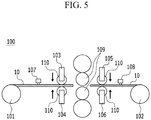
- FIG. 5 is a schematic view of the stopper moving toward the electrode side when a disconnection occurs in the electrode in FIG. 4
- FIG. 6 is a schematic view of movement of the electrode by the roller of the stopper in FIG. 5
- FIG. 7 is a schematic view that shows the disconnected portion of the electrode is connected.
- the first tension sensor 107 and the second tension sensor 108 detect abnormal tension, and the tension abnormality detection signal may be transmitted to the first stopper 103, the second stopper 104, the third stopper 105, and the fourth stopper 106.
- the first stopper 103, the second stopper 104, the third stopper 105, and the fourth stopper 016 may move towards the electrode 10.
- the first stopper 103 moves downward and thus contacts the top surface of the disconnected electrode 10 and the second stopper 104 moves upward and thus contacts the bottom surface of the disconnected electrode 10, such that the disconnected electrode 10 can be fixed to prevent from being separated from the movement path.
- the third stopper 103 moves downward to contact the top surface of the disconnected electrode 10 and the second stopper 104 moves upward to contact the bottom surface of the disconnected electrode 10, such that the disconnected electrode 10 can be fixed to prevent separation from the movement path.
- moving rollers110 formed in the first stopper 103, the second stopper 104, the third stopper 105, and the fourth stopper 106 operate such that the disconnected electrode 10 can move toward the rollers 109 while the first stopper 103, the second stopper 104, the third stopper 105, and the fourth stopper 106 fix the disconnected electrode 10.
- the moving roller 110 of the first stopper 103 and the moving roller 110 of the fourth stopper 106 rotate along the counterclockwise direction and the moving roller 110 of the second stopper 104 and the moving roller 110 of the third stopper 105 rotate along the clockwise direction such that the disconnected electrode 10 between the moving roller 110 of the first stopper 103 and the moving roller 110 of the second stopper 104 move toward the roller 109 and the moving roller 110 of the third stopper 105 and the disconnected electrode 10 between the moving roller 110 of the fourth stopper 106 may move toward the roller 109.
- the winding unit 102 may move the electrode 100 while rotating in a direction opposite to the direction in which the manufacturing device 100 operates normally.
- the unwinding unit 101 may rotate in a rotating direction in which the manufacturing device 100 operates normally.
- the disconnected electrode 10 between the moving roller 110 of the third stopper 105 and the moving roller 110 of the fourth stopper 106 toward the roller 109 when moving the disconnected electrode 10 between the moving roller 110 of the third stopper 105 and the moving roller 110 of the fourth stopper 106 toward the roller 109, the disconnected electrode 10 between the moving roller 110 of the first stopper 103 and the moving roller 110 of the second stopper 104 may not move.
- connection member may be an insulating tape or the like.
- the operator does not need to stop the operation of the battery manufacturing device 100 to connect the disconnected portion C of the electrode 10, and also prevents the detachment of the electrode 10 due to disconnection, thereby improving manufacturing productivity.
- the battery manufacturing device prevents the disconnected electrode from detaching in the rolling process by using a stopper, and can operate the disconnected electrode without stopping the operation of the battery manufacturing device, thereby improving the operating rate and productivity.
Landscapes
- Engineering & Computer Science (AREA)
- Manufacturing & Machinery (AREA)
- Chemical & Material Sciences (AREA)
- Chemical Kinetics & Catalysis (AREA)
- Electrochemistry (AREA)
- General Chemical & Material Sciences (AREA)
- Battery Electrode And Active Subsutance (AREA)
- Secondary Cells (AREA)
Abstract
Description
- This application claims priority to and the benefit of Korean Patent Application No.
10-2018-0143839 - The present invention relates to a battery manufacturing device and a battery manufacturing method using the same.
- Recently, interest in a price increase of energy sources due to depletion of fossil fuels and environmental pollution has increased, and demand for environmentally-friendly alternative energy sources has become an indispensable factor for future life. Therefore, research on various power generation technologies such as nuclear power, solar power, wind power, and tidal power has been continuously conducted, and interest in a power storing apparatus for efficiently using energy generated as described above has also increased.
- Particularly, in accordance with the development of technologies for mobile devices and an increase in demand for the mobile devices, a demand for batteries as an energy source has rapidly increased. Therefore, many studies on the batteries that may satisfy various needs have been conducted.
- Typically, there is a high demand for a prismatic rechargeable battery and a pouch type of rechargeable battery that may be used in products such as mobile phones due to a small thickness in terms of a shape of a battery, and there is a high demand for a lithium rechargeable battery such as a lithium ion battery or a lithium ion polymer battery having advantages such as high energy density, high discharging voltage, and output stability in terms of a material of the battery.
- The rechargeable battery is manufactured by accommodating an electrode assembly having a structure in which a positive electrode, a negative electrode, and a separator disposed between the positive electrode and the negative electrode are stacked in a battery case.
-
FIG. 1 is a top plan view of an electrode of a rechargeable, to which an active material is applied.FIG. 2 is a side view ofFIG. 1 viewed from the A direction.FIG. 3 is a schematic diagram of a state in which the electrode is disconnected during a rolling process of the electrode ofFIG. 1 . - Referring to
FIG. 1 to FIG. 3 , in anelectrode 10 of a rechargeable battery, anactive material 12 is applied to both sides of a metalcurrent collector 11, and a rolling process is performed to increase the density per unit volume of the applied active material. However, a step is formed between a portion where theactive material 12 is applied in the metalcurrent collector 11 and an uncoated region where theactive material 12 is not applied, and thus a stress is concentrated in the step portion during the rolling process of theelectrode 10, thereby causing theelectrode 10 to be bent or to have a disconnection B in the uncoated region. - When such a disconnection occurs in the
electrode 10 during the rolling process, thedisconnected electrode 10 may be separated from an original movement path, and an operator needs to stop both the manufacturing device and related equipment in order to reconnect thedisconnected electrode 10, thereby causing a problem that the operation rate and productivity of the manufacturing equipment are significantly deteriorated. - Therefore, there is a need for a technology that can fundamentally solve this problem.
- In order to solve the above-stated problems, exemplary embodiments of the present invention provide a battery manufacturing device and a battery manufacturing method using the same to prevent an electrode from being disconnected in the rolling process and to reconnect the disconnected electrode without stopping the operation of the battery manufacturing device.
- In order to achieve such a purpose, a battery manufacturing device according to the present invention includes: a fixed roller that moves an electrode where an active material is applied; a roller that rolls the electrode; and a stopper that is disposed between the fixed roller and the roller, and when the electrode is disconnected, moves the disconnected electrode.
- The battery manufacturing device may further include a tension sensor that detects a tension variation of the electrode.
- The tension sensor may transmit a tension abnormality detection signal to the stopper.
- The stopper may move toward the electrode in response to the tension abnormality detection signal.
- The stopper may include a moving roller that moves the disconnected electrode.
- The stopper may include a first stopper, a second stopper, a third stopper, and a fourth stopper.
- When the tension sensor does not detect tension abnormality in the electrode, the first stopper and the third stopper may be spaced upwardly from the top of the electrode, and the second stopper and the fourth stopper may be spaced downwardly from the bottom of the electrode.
- When the tension sensor detects tension abnormality in the electrode, the first stopper, the second stopper, the third stopper, and the fourth stopper may move toward the electrode, and the first stopper and the third stopper may contact the top of a disconnected electrode and the second stopper and the fourth stopper may contact the bottom of the disconnected electrode to thereby fix the disconnected electrode.
- The fixed roller may include an unwinding unit and a winding unit.
- When the disconnected electrode between the third stopper and the fourth stopper moves toward the roller, the winding unit may rotate in a direction that is opposite to a direction in which the winding unit rotates when the battery manufacturing device normally operates.
- When the disconnected electrode between the first stopper and the second stopper moves toward the roller, the unwinding unit may rotate in a direction in which the winding unit rotates when the battery manufacturing device normally operates.
- A battery manufacturing method using the battery manufacturing device according to the present invention includes:
- introducing an electrode to which an active material is applied to a roller by using a fixed roller;
- measuring a tension of the electrode by operating a tension sensor;
- transmitting a tension abnormality detection signal to a stopper by the tension sensor;
- holding a disconnected electrode by moving toward the electrode by the stopper;
- moving the disconnected electrode to connect the disconnected electrode by the stopper; and
- connecting a disconnection portion of the electrode.
-
-
FIG. 1 is a top plan view of an electrode of a rechargeable, to which an active material is applied. -
FIG. 2 is a side view ofFIG. 1 viewed from the A direction. -
FIG. 3 is a schematic diagram of a state in which the electrode is disconnected during a rolling process of the electrode ofFIG. 1 . -
FIG. 4 is a schematic view of a battery manufacturing device according to an exemplary embodiment of the present invention. -
FIG. 5 to FIG. 7 illustrate a battery manufacturing method according to another exemplary embodiment of the present invention. - Hereinafter, various exemplary embodiments of the present invention will be described in detail with reference to the accompanying drawings so that those skilled in the art may easily practice the present invention. The present invention may be embodied in many different forms, and should not be construed as limited to the exemplary embodiments set forth herein.
- In addition, unless explicitly described to the contrary, the word "comprise" and variations such as "comprises" or "comprising" will be understood to imply the inclusion of stated elements but not the exclusion of any other elements.
- In addition, throughout the specification, the phrase "top plan view" means that a target part is vertically viewed from the tope.
- In addition, throughout the specification, the phrase "cross-sectional view" means that a target part is viewed from the side.
- In addition, throughout the specification, "top (surface)" of the electrode means a surface located in the opposite direction of gravity, and "bottom (surface)" of the electrode means the surface located opposite to the top surface.
-
FIG. 4 is a schematic view of a battery manufacturing device according to an exemplary embodiment of the present invention. - Referring to
FIG. 4 , abattery manufacturing device 100 includes anunwinding unit 101, awinding unit 102,rollers 109, afirst stopper 103, asecond stopper 104, athird stopper 105, and afourth stopper 106. Theroller 109 is disposed between theunwinding unit 101 and thewinding unit 102 to roll anelectrode 10 that moves to thewinding unit 102 from theunwinding unit 101. The structure of theroller 109 is not particularly limited, but may be, for example, a roller capable of compressing the surface of theelectrode 10. - While the
manufacturing device 100 normally operates, a constant tension may be maintained at theelectrode 10 between theunwinding unit 101 and thewinding unit 102. Themanufacturing device 100 may include afirst tension sensor 107 and asecond tension sensor 108 that detect tension. - The
first tension sensor 107 may be located between theunwinding unit 101 and thefirst stopper 103 andsecond stopper 104, and thesecond tension sensor 108 may be located between thewinding unit 102 and thethird stopper 105 andfourth stopper 106. - The
first tension sensor 107 may transmit a tension abnormality detection signal to thefirst stopper 103 and thesecond stopper 104 when the tension is out of a threshold range. Similarly, thesecond tension sensor 108 may transmit a tension abnormality detection signal to thethird stopper 105 and thefourth stopper 106. The tension abnormality detection signal can be transmitted to thefirst stopper 103, thesecond stopper 104, thethird stopper 105, and thefourth stopper 106 by wire or wirelessly. - As long as the change in the tension can be accurately sensed, the tension sensor is not particularly limited, and for example, the
first tension sensor 107 and thesecond tension sensor 108 may each be a load cell. Since the operation principle of the load cell is already known in the art, a description thereof will be omitted. An operator may select an appropriate load cell in consideration of the tension range maintained at theelectrode 10 and use it as thefirst tension sensor 107 and thesecond tension sensor 108. - The
first stopper 103 and thesecond stopper 104 may be formed between theunwinding unit 101 and theroller 109 at a portion of theelectrode 10 which is introduced into therollers 109. Athird stopper 105 and afourth stopper 106 may be formed between the windingunit 102 and theroller 109 at a portion of theelectrode 10 discharged from therollers 109. - When disconnection does not occur in the
electrode 10 and thebattery manufacturing device 100 operates normally, thefirst stopper 103 may be spaced upwardly from an upper surface of theelectrode 10. Thesecond stopper 104 may be spaced downward from the lower surface of theelectrode 10. Likewise, thethird stopper 105 can be spaced upwardly from the upper surface ofelectrode 10. Thefourth stopper 106 may be spaced downward from the lower surface of theelectrode 10. - In addition, when the
first tension sensor 107 and thesecond tension sensor 108 receive a tension abnormality detection signal, thefirst stopper 103, thesecond stopper 104, thethird stopper 105, and the fourth stopper 016 may move toward theelectrode 10, respectively. In addition, thefirst stopper 103, thesecond stopper 104, thethird stopper 105, and the fourth stopper 016 may include a movingroller 110 to press and move theelectrode 10, respectively. - Hereinafter, a method of manufacturing a battery using a battery manufacturing device according to the present exemplary embodiment described above, specifically a process of rolling an electrode active material, will be described.
-
FIG. 5 to FIG. 7 illustrate a battery manufacturing method according to another exemplary embodiment of the present invention.FIG. 5 is a schematic view of the stopper moving toward the electrode side when a disconnection occurs in the electrode inFIG. 4 ,FIG. 6 is a schematic view of movement of the electrode by the roller of the stopper inFIG. 5 , andFIG. 7 is a schematic view that shows the disconnected portion of the electrode is connected. - Referring to
FIG. 5 , when the tension of theelectrode 10 is out of the threshold range or breakage occurs, thefirst tension sensor 107 and thesecond tension sensor 108 detect abnormal tension, and the tension abnormality detection signal may be transmitted to thefirst stopper 103, thesecond stopper 104, thethird stopper 105, and thefourth stopper 106. In addition, in response to the tension anomaly detection signal, thefirst stopper 103, thesecond stopper 104, thethird stopper 105, and the fourth stopper 016 may move towards theelectrode 10. - Specifically, the
first stopper 103 moves downward and thus contacts the top surface of the disconnectedelectrode 10 and thesecond stopper 104 moves upward and thus contacts the bottom surface of the disconnectedelectrode 10, such that the disconnectedelectrode 10 can be fixed to prevent from being separated from the movement path. Similarly, thethird stopper 103 moves downward to contact the top surface of the disconnectedelectrode 10 and thesecond stopper 104 moves upward to contact the bottom surface of the disconnectedelectrode 10, such that the disconnectedelectrode 10 can be fixed to prevent separation from the movement path. - Referring to
FIG. 6 andFIG. 7 , moving rollers110 formed in thefirst stopper 103, thesecond stopper 104, thethird stopper 105, and thefourth stopper 106 operate such that the disconnectedelectrode 10 can move toward therollers 109 while thefirst stopper 103, thesecond stopper 104, thethird stopper 105, and thefourth stopper 106 fix the disconnectedelectrode 10. - In this case, the moving
roller 110 of thefirst stopper 103 and the movingroller 110 of thefourth stopper 106 rotate along the counterclockwise direction and the movingroller 110 of thesecond stopper 104 and the movingroller 110 of thethird stopper 105 rotate along the clockwise direction such that the disconnectedelectrode 10 between the movingroller 110 of thefirst stopper 103 and the movingroller 110 of thesecond stopper 104 move toward theroller 109 and the movingroller 110 of thethird stopper 105 and the disconnectedelectrode 10 between the movingroller 110 of thefourth stopper 106 may move toward theroller 109. When the disconnectedelectrode 10 between the movingroller 110 of thethird stopper 105 and the movingroller 110 of thefourth stopper 106 moves toward theroller 109, the windingunit 102 may move theelectrode 100 while rotating in a direction opposite to the direction in which themanufacturing device 100 operates normally. - When the disconnected
electrode 10 between the movingroller 110 of thefirst stopper 103 and the movingroller 110 of thesecond stopper 104 moves toward theroller 109, the unwindingunit 101 may rotate in a rotating direction in which themanufacturing device 100 operates normally. - As an exemplary variation, when moving the disconnected
electrode 10 between the movingroller 110 of thethird stopper 105 and the movingroller 110 of thefourth stopper 106 toward theroller 109, the disconnectedelectrode 10 between the movingroller 110 of thefirst stopper 103 and the movingroller 110 of thesecond stopper 104 may not move. - An operator may reconnect a disconnected portion C of the moved
electrode 10 by using a connection member. Here, the connection member may be an insulating tape or the like. - With such a structure, the operator does not need to stop the operation of the
battery manufacturing device 100 to connect the disconnected portion C of theelectrode 10, and also prevents the detachment of theelectrode 10 due to disconnection, thereby improving manufacturing productivity. - Those of ordinary skill in the field of the present invention will be able to make various applications and modifications within the scope of the present invention based on the contents.
- As described above, the battery manufacturing device according to the present invention prevents the disconnected electrode from detaching in the rolling process by using a stopper, and can operate the disconnected electrode without stopping the operation of the battery manufacturing device, thereby improving the operating rate and productivity.
Claims (12)
- A battery manufacturing device comprising:a fixed roller that moves an electrode where an active material is applied;a roller that rolls the electrode; anda stopper that is disposed between the fixed roller and the roller, and when the electrode is disconnected, moves the disconnected electrode.
- The battery manufacturing device of claim 1, further comprising a tension sensor that detects a tension variation of the electrode.
- The battery manufacturing device of claim 2, wherein the tension sensor transmits a tension abnormality detection signal to the stopper.
- The battery manufacturing device of claim 4, wherein the stopper moves toward the electrode in response to the tension abnormality detection signal.
- The battery manufacturing device of claim 3, wherein the stopper comprises a moving roller that moves the disconnected electrode.
- The battery manufacturing device of claim 5, wherein the stopper comprises a first stopper, a second stopper, a third stopper, and a fourth stopper.
- The battery manufacturing device of claim 6, wherein when the tension sensor does not detect tension abnormality in the electrode, the first stopper and the third stopper are spaced upwardly from the top of the electrode, and the second stopper and the fourth stopper are spaced downwardly from the bottom of the electrode.
- The battery manufacturing device of claim 6, wherein when the tension sensor detects tension abnormality in the electrode, the first stopper, the second stopper, the third stopper, and the fourth stopper move toward the electrode, and the first stopper and the third stopper contact the top of a disconnected electrode and the second stopper and the fourth stopper contact the bottom of the disconnected electrode to thereby fix the disconnected electrode.
- The battery manufacturing device of claim 6, wherein the fixed roller comprises an unwinding unit and a winding unit.
- The battery manufacturing device of claim 9, wherein when the disconnected electrode between the third stopper and the fourth stopper moves toward the roller, the winding unit rotates in a direction that is opposite to a direction in which the winding unit rotates when the battery manufacturing device normally operates.
- The battery manufacturing device of claim 9, wherein when the disconnected electrode between the first stopper and the second stopper moves toward the roller, the unwinding unit rotates in a direction in which the winding unit rotates when the battery manufacturing device normally operates.
- A manufacturing method of a battery, comprising:introducing an electrode to which an active material is applied to a roller by using a fixed roller;measuring a tension of the electrode by operating a tension sensor;transmitting a tension abnormality detection signal to a stopper by the tension sensor;holding a disconnected electrode by moving toward the electrode by the stopper;moving the disconnected electrode to connect the disconnected electrode by the stopper; andconnecting a disconnection portion of the electrode.
Applications Claiming Priority (2)
| Application Number | Priority Date | Filing Date | Title |
|---|---|---|---|
| KR1020180143839A KR102541536B1 (en) | 2018-11-20 | 2018-11-20 | Battery cell manufacturing device and battery cell manufacturing method using the same |
| PCT/KR2019/014387 WO2020105884A1 (en) | 2018-11-20 | 2019-10-29 | Apparatus for manufacturing battery and method for manufacturing battery by using same |
Publications (3)
| Publication Number | Publication Date |
|---|---|
| EP3764430A1 true EP3764430A1 (en) | 2021-01-13 |
| EP3764430A4 EP3764430A4 (en) | 2021-06-02 |
| EP3764430B1 EP3764430B1 (en) | 2026-01-14 |
Family
ID=70773282
Family Applications (1)
| Application Number | Title | Priority Date | Filing Date |
|---|---|---|---|
| EP19888148.4A Active EP3764430B1 (en) | 2018-11-20 | 2019-10-29 | Battery manufacturing device and battery manufacturing method using the same |
Country Status (8)
| Country | Link |
|---|---|
| US (1) | US12021182B2 (en) |
| EP (1) | EP3764430B1 (en) |
| JP (1) | JP7094602B2 (en) |
| KR (1) | KR102541536B1 (en) |
| CN (1) | CN111771299B (en) |
| ES (1) | ES3063101T3 (en) |
| PL (1) | PL3764430T3 (en) |
| WO (1) | WO2020105884A1 (en) |
Families Citing this family (6)
| Publication number | Priority date | Publication date | Assignee | Title |
|---|---|---|---|---|
| WO2021118141A1 (en) * | 2019-12-09 | 2021-06-17 | 주식회사 엘지에너지솔루션 | Manufacturing apparatus for electrode for secondary battery and manufacturing method for electrode for secondary battery, comprising heat treatment part and heat treatment process for heat treatment of sheet-shaped current collector before coating with electrode active material slurry, respectively |
| KR102840394B1 (en) * | 2020-04-14 | 2025-07-29 | 주식회사 엘지에너지솔루션 | System and method for transferring electrode substrate from winding roll |
| KR102601968B1 (en) * | 2021-09-02 | 2023-11-14 | 주식회사 엘지에너지솔루션 | Electrode connection cause determination system and roll map producing system using the same |
| US20240097218A1 (en) | 2022-09-15 | 2024-03-21 | Lg Energy Solution, Ltd. | Systems and methods for generating roll map and manufacturing battery using roll map |
| KR20240038554A (en) | 2022-09-15 | 2024-03-25 | 주식회사 엘지에너지솔루션 | Roll map, making up method of roll map and making up system thereof |
| KR20250042985A (en) | 2023-09-21 | 2025-03-28 | 주식회사 엘지에너지솔루션 | Apparatus of manufacturing electrode and method of manufacturing electrode using the same |
Family Cites Families (21)
| Publication number | Priority date | Publication date | Assignee | Title |
|---|---|---|---|---|
| JP2001118573A (en) * | 1999-10-20 | 2001-04-27 | Toshiba Battery Co Ltd | Apparatus for processing sheet-shape electrode material |
| KR100635758B1 (en) * | 2005-01-24 | 2006-10-17 | 삼성에스디아이 주식회사 | Electrode plate winding device for secondary battery |
| US7967594B2 (en) | 2005-01-25 | 2011-06-28 | Ishikawajima-Harima Heavy Industries Co., Ltd. | Facility for forming cell electrode plate |
| JP2007008721A (en) | 2005-06-01 | 2007-01-18 | Infinite Nishi:Kk | Yarn delivery device and yarn piecing method using this device |
| JP4930344B2 (en) | 2007-11-28 | 2012-05-16 | パナソニック株式会社 | Crimping tool protection sheet feeding method and apparatus |
| JP5532507B2 (en) | 2008-10-01 | 2014-06-25 | 日本電気硝子株式会社 | Glass roll and glass roll processing method |
| JP5435267B2 (en) | 2008-10-01 | 2014-03-05 | 日本電気硝子株式会社 | Glass roll, glass roll manufacturing apparatus, and glass roll manufacturing method |
| JP2010198770A (en) | 2009-02-23 | 2010-09-09 | Sanyo Electric Co Ltd | Method and apparatus for manufacturing wound electrode assembly |
| KR100972659B1 (en) | 2009-09-30 | 2010-07-27 | 주식회사 에이치앤티 | Soft and hard copper wire rolling apparatus |
| JP5468407B2 (en) * | 2010-02-04 | 2014-04-09 | Ckd株式会社 | Battery manufacturing equipment |
| WO2011158584A1 (en) | 2010-06-18 | 2011-12-22 | コニカミノルタホールディングス株式会社 | Conveyance device and conveyance method for thin film glass |
| KR101326628B1 (en) * | 2010-12-02 | 2013-11-07 | 주식회사 엘지화학 | Novel Device for Notching and Secondary Battery Manufactured Using the Same |
| JP5665532B2 (en) * | 2010-12-27 | 2015-02-04 | 株式会社東芝 | manufacturing device |
| JP6007397B2 (en) * | 2012-10-17 | 2016-10-12 | エリーパワー株式会社 | Secondary battery manufacturing method and manufacturing apparatus |
| JP5622893B1 (en) * | 2013-05-24 | 2014-11-12 | 富士機械工業株式会社 | Double-side coating system |
| KR101756501B1 (en) * | 2013-10-30 | 2017-07-10 | 주식회사 엘지화학 | Apparatus of pressing electrode sheet |
| CN104009249B (en) | 2014-06-05 | 2016-08-24 | 深圳市赢合科技股份有限公司 | A kind of up-coiler |
| KR101694120B1 (en) * | 2015-04-21 | 2017-01-09 | 씨아이에스(주) | Winding apparatus for rolling process in the manufacturing of secondary battery electrode, and manufacturing method of secondary battery electrode for the same |
| JP6027701B1 (en) | 2016-05-20 | 2016-11-16 | 大野ロール株式会社 | Roll press machine with wrinkle prevention device and roll press method |
| KR101875080B1 (en) * | 2017-03-31 | 2018-07-05 | (주)피엔티 | Apparatus for pressing electrode of secondary battery |
| CN108680581A (en) * | 2018-06-12 | 2018-10-19 | 广州超音速自动化科技股份有限公司 | A kind of lithium electrode piece independent detection machine |
-
2018
- 2018-11-20 KR KR1020180143839A patent/KR102541536B1/en active Active
-
2019
- 2019-10-29 JP JP2020547347A patent/JP7094602B2/en active Active
- 2019-10-29 US US17/043,176 patent/US12021182B2/en active Active
- 2019-10-29 WO PCT/KR2019/014387 patent/WO2020105884A1/en not_active Ceased
- 2019-10-29 PL PL19888148.4T patent/PL3764430T3/en unknown
- 2019-10-29 ES ES19888148T patent/ES3063101T3/en active Active
- 2019-10-29 CN CN201980013422.3A patent/CN111771299B/en active Active
- 2019-10-29 EP EP19888148.4A patent/EP3764430B1/en active Active
Also Published As
| Publication number | Publication date |
|---|---|
| CN111771299A (en) | 2020-10-13 |
| ES3063101T3 (en) | 2026-04-15 |
| JP7094602B2 (en) | 2022-07-04 |
| KR102541536B1 (en) | 2023-06-08 |
| US20210057774A1 (en) | 2021-02-25 |
| EP3764430B1 (en) | 2026-01-14 |
| PL3764430T3 (en) | 2026-04-20 |
| KR20200059026A (en) | 2020-05-28 |
| US12021182B2 (en) | 2024-06-25 |
| CN111771299B (en) | 2023-04-18 |
| WO2020105884A1 (en) | 2020-05-28 |
| JP2021516432A (en) | 2021-07-01 |
| EP3764430A4 (en) | 2021-06-02 |
Similar Documents
| Publication | Publication Date | Title |
|---|---|---|
| US12021182B2 (en) | Battery manufacturing method | |
| CN108886179B (en) | A battery cell capable of measuring the internal temperature of the battery cell | |
| KR101604052B1 (en) | Removal equipment for a electric conduction plate of electric double layer capacitors battery for electric vehicle | |
| KR101840859B1 (en) | Apparatus for Attaching the Adhesion Member for Fixing Battery Assembly | |
| EP3955354A1 (en) | Electrode assembly manufacturing device, electrode assembly manufactured thereby and secondary battery | |
| US11411287B2 (en) | Three-electrode-system-type electrode potential measurement device including short-circuit prevention member | |
| KR102474625B1 (en) | Battery manufacturing device and manufacturing method of battery | |
| KR20140048615A (en) | Press device for jelly roll-secondary battery and fabricating method of secondary battery using the same | |
| KR101280573B1 (en) | Device for Measuring Dimension of Cylindrical Battery Cell | |
| KR101789854B1 (en) | System for judging a skew fail in a secondary battery and method thereof | |
| WO2023173931A1 (en) | Winding apparatus and method | |
| US20200251743A1 (en) | Electrode, electrode assembly and method for manufacturing the same | |
| US9799875B2 (en) | Electrode assembly and rechargeable battery having electrode tab | |
| KR101590671B1 (en) | Ultrasonic welding assembly and Fabricating method of secondary battery using the same | |
| KR102389191B1 (en) | Battery pack manufacturing devide and manufacturing method of battery pack | |
| KR101590672B1 (en) | Ultrasonic welding assembly and Fabricating method of secondary battery using the same | |
| US10615621B2 (en) | Apparatus for charging and discharging battery cell comprising insulation mask | |
| KR20170141064A (en) | Apparatus of Attaching Sheet to Battery Pack Having Label Array Sensor | |
| KR100635758B1 (en) | Electrode plate winding device for secondary battery | |
| KR101818790B1 (en) | Negative tab fixing structure for secondary battery | |
| WO2025236425A1 (en) | Detection device and battery production system | |
| KR20250029656A (en) | Battery cell insulation tape attachment system | |
| KR20250026039A (en) | Battery cell insulation tape attachment system | |
| KR20210030789A (en) | Apparatus for manufacturing cylindrical battery | |
| KR20170046513A (en) | Electrode assembly |
Legal Events
| Date | Code | Title | Description |
|---|---|---|---|
| STAA | Information on the status of an ep patent application or granted ep patent |
Free format text: STATUS: THE INTERNATIONAL PUBLICATION HAS BEEN MADE |
|
| PUAI | Public reference made under article 153(3) epc to a published international application that has entered the european phase |
Free format text: ORIGINAL CODE: 0009012 |
|
| STAA | Information on the status of an ep patent application or granted ep patent |
Free format text: STATUS: REQUEST FOR EXAMINATION WAS MADE |
|
| 17P | Request for examination filed |
Effective date: 20201005 |
|
| AK | Designated contracting states |
Kind code of ref document: A1 Designated state(s): AL AT BE BG CH CY CZ DE DK EE ES FI FR GB GR HR HU IE IS IT LI LT LU LV MC MK MT NL NO PL PT RO RS SE SI SK SM TR |
|
| AX | Request for extension of the european patent |
Extension state: BA ME |
|
| A4 | Supplementary search report drawn up and despatched |
Effective date: 20210503 |
|
| RIC1 | Information provided on ipc code assigned before grant |
Ipc: H01M 4/04 20060101AFI20210426BHEP Ipc: B65H 23/04 20060101ALI20210426BHEP Ipc: B65H 26/04 20060101ALI20210426BHEP |
|
| RAP1 | Party data changed (applicant data changed or rights of an application transferred) |
Owner name: LG ENERGY SOLUTION LTD. |
|
| DAV | Request for validation of the european patent (deleted) | ||
| DAX | Request for extension of the european patent (deleted) | ||
| RAP3 | Party data changed (applicant data changed or rights of an application transferred) |
Owner name: LG ENERGY SOLUTION, LTD. |
|
| STAA | Information on the status of an ep patent application or granted ep patent |
Free format text: STATUS: EXAMINATION IS IN PROGRESS |
|
| 17Q | First examination report despatched |
Effective date: 20230512 |
|
| GRAP | Despatch of communication of intention to grant a patent |
Free format text: ORIGINAL CODE: EPIDOSNIGR1 |
|
| STAA | Information on the status of an ep patent application or granted ep patent |
Free format text: STATUS: GRANT OF PATENT IS INTENDED |
|
| INTG | Intention to grant announced |
Effective date: 20251022 |
|
| GRAS | Grant fee paid |
Free format text: ORIGINAL CODE: EPIDOSNIGR3 |
|
| P01 | Opt-out of the competence of the unified patent court (upc) registered |
Free format text: CASE NUMBER: UPC_APP_0012117_3764430/2025 Effective date: 20251105 |
|
| GRAA | (expected) grant |
Free format text: ORIGINAL CODE: 0009210 |
|
| STAA | Information on the status of an ep patent application or granted ep patent |
Free format text: STATUS: THE PATENT HAS BEEN GRANTED |
|
| AK | Designated contracting states |
Kind code of ref document: B1 Designated state(s): AL AT BE BG CH CY CZ DE DK EE ES FI FR GB GR HR HU IE IS IT LI LT LU LV MC MK MT NL NO PL PT RO RS SE SI SK SM TR |
|
| REG | Reference to a national code |
Ref country code: CH Ref legal event code: F10 Free format text: ST27 STATUS EVENT CODE: U-0-0-F10-F00 (AS PROVIDED BY THE NATIONAL OFFICE) Effective date: 20260114 Ref country code: GB Ref legal event code: FG4D |
|
| REG | Reference to a national code |
Ref country code: DE Ref legal event code: R096 Ref document number: 602019080457 Country of ref document: DE |
|
| REG | Reference to a national code |
Ref country code: IE Ref legal event code: FG4D |
|
| REG | Reference to a national code |
Ref country code: ES Ref legal event code: FG2A Ref document number: 3063101 Country of ref document: ES Kind code of ref document: T3 Effective date: 20260415 |