EP3764421A1 - Battery module comprising connector having bidirectional fastening structure - Google Patents
Battery module comprising connector having bidirectional fastening structure Download PDFInfo
- Publication number
- EP3764421A1 EP3764421A1 EP19891755.1A EP19891755A EP3764421A1 EP 3764421 A1 EP3764421 A1 EP 3764421A1 EP 19891755 A EP19891755 A EP 19891755A EP 3764421 A1 EP3764421 A1 EP 3764421A1
- Authority
- EP
- European Patent Office
- Prior art keywords
- fastening part
- module
- slide rail
- battery module
- battery
- Prior art date
- Legal status (The legal status is an assumption and is not a legal conclusion. Google has not performed a legal analysis and makes no representation as to the accuracy of the status listed.)
- Granted
Links
Images


Classifications
-
- H—ELECTRICITY
- H01—ELECTRIC ELEMENTS
- H01M—PROCESSES OR MEANS, e.g. BATTERIES, FOR THE DIRECT CONVERSION OF CHEMICAL ENERGY INTO ELECTRICAL ENERGY
- H01M50/00—Constructional details or processes of manufacture of the non-active parts of electrochemical cells other than fuel cells, e.g. hybrid cells
- H01M50/20—Mountings; Secondary casings or frames; Racks, modules or packs; Suspension devices; Shock absorbers; Transport or carrying devices; Holders
-
- H—ELECTRICITY
- H01—ELECTRIC ELEMENTS
- H01M—PROCESSES OR MEANS, e.g. BATTERIES, FOR THE DIRECT CONVERSION OF CHEMICAL ENERGY INTO ELECTRICAL ENERGY
- H01M10/00—Secondary cells; Manufacture thereof
- H01M10/42—Methods or arrangements for servicing or maintenance of secondary cells or secondary half-cells
- H01M10/425—Structural combination with electronic components, e.g. electronic circuits integrated to the outside of the casing
-
- H—ELECTRICITY
- H01—ELECTRIC ELEMENTS
- H01M—PROCESSES OR MEANS, e.g. BATTERIES, FOR THE DIRECT CONVERSION OF CHEMICAL ENERGY INTO ELECTRICAL ENERGY
- H01M50/00—Constructional details or processes of manufacture of the non-active parts of electrochemical cells other than fuel cells, e.g. hybrid cells
- H01M50/20—Mountings; Secondary casings or frames; Racks, modules or packs; Suspension devices; Shock absorbers; Transport or carrying devices; Holders
- H01M50/204—Racks, modules or packs for multiple batteries or multiple cells
-
- H—ELECTRICITY
- H01—ELECTRIC ELEMENTS
- H01M—PROCESSES OR MEANS, e.g. BATTERIES, FOR THE DIRECT CONVERSION OF CHEMICAL ENERGY INTO ELECTRICAL ENERGY
- H01M50/00—Constructional details or processes of manufacture of the non-active parts of electrochemical cells other than fuel cells, e.g. hybrid cells
- H01M50/20—Mountings; Secondary casings or frames; Racks, modules or packs; Suspension devices; Shock absorbers; Transport or carrying devices; Holders
- H01M50/204—Racks, modules or packs for multiple batteries or multiple cells
- H01M50/207—Racks, modules or packs for multiple batteries or multiple cells characterised by their shape
- H01M50/209—Racks, modules or packs for multiple batteries or multiple cells characterised by their shape adapted for prismatic or rectangular cells
-
- H—ELECTRICITY
- H01—ELECTRIC ELEMENTS
- H01M—PROCESSES OR MEANS, e.g. BATTERIES, FOR THE DIRECT CONVERSION OF CHEMICAL ENERGY INTO ELECTRICAL ENERGY
- H01M50/00—Constructional details or processes of manufacture of the non-active parts of electrochemical cells other than fuel cells, e.g. hybrid cells
- H01M50/20—Mountings; Secondary casings or frames; Racks, modules or packs; Suspension devices; Shock absorbers; Transport or carrying devices; Holders
- H01M50/244—Secondary casings; Racks; Suspension devices; Carrying devices; Holders characterised by their mounting method
-
- H—ELECTRICITY
- H01—ELECTRIC ELEMENTS
- H01M—PROCESSES OR MEANS, e.g. BATTERIES, FOR THE DIRECT CONVERSION OF CHEMICAL ENERGY INTO ELECTRICAL ENERGY
- H01M50/00—Constructional details or processes of manufacture of the non-active parts of electrochemical cells other than fuel cells, e.g. hybrid cells
- H01M50/20—Mountings; Secondary casings or frames; Racks, modules or packs; Suspension devices; Shock absorbers; Transport or carrying devices; Holders
- H01M50/249—Mountings; Secondary casings or frames; Racks, modules or packs; Suspension devices; Shock absorbers; Transport or carrying devices; Holders specially adapted for aircraft or vehicles, e.g. cars or trains
-
- H—ELECTRICITY
- H01—ELECTRIC ELEMENTS
- H01M—PROCESSES OR MEANS, e.g. BATTERIES, FOR THE DIRECT CONVERSION OF CHEMICAL ENERGY INTO ELECTRICAL ENERGY
- H01M50/00—Constructional details or processes of manufacture of the non-active parts of electrochemical cells other than fuel cells, e.g. hybrid cells
- H01M50/20—Mountings; Secondary casings or frames; Racks, modules or packs; Suspension devices; Shock absorbers; Transport or carrying devices; Holders
- H01M50/262—Mountings; Secondary casings or frames; Racks, modules or packs; Suspension devices; Shock absorbers; Transport or carrying devices; Holders with fastening means, e.g. locks
-
- H—ELECTRICITY
- H01—ELECTRIC ELEMENTS
- H01M—PROCESSES OR MEANS, e.g. BATTERIES, FOR THE DIRECT CONVERSION OF CHEMICAL ENERGY INTO ELECTRICAL ENERGY
- H01M50/00—Constructional details or processes of manufacture of the non-active parts of electrochemical cells other than fuel cells, e.g. hybrid cells
- H01M50/50—Current conducting connections for cells or batteries
-
- H—ELECTRICITY
- H01—ELECTRIC ELEMENTS
- H01M—PROCESSES OR MEANS, e.g. BATTERIES, FOR THE DIRECT CONVERSION OF CHEMICAL ENERGY INTO ELECTRICAL ENERGY
- H01M50/00—Constructional details or processes of manufacture of the non-active parts of electrochemical cells other than fuel cells, e.g. hybrid cells
- H01M50/50—Current conducting connections for cells or batteries
- H01M50/502—Interconnectors for connecting terminals of adjacent batteries; Interconnectors for connecting cells outside a battery casing
- H01M50/503—Interconnectors for connecting terminals of adjacent batteries; Interconnectors for connecting cells outside a battery casing characterised by the shape of the interconnectors
-
- H—ELECTRICITY
- H01—ELECTRIC ELEMENTS
- H01M—PROCESSES OR MEANS, e.g. BATTERIES, FOR THE DIRECT CONVERSION OF CHEMICAL ENERGY INTO ELECTRICAL ENERGY
- H01M50/00—Constructional details or processes of manufacture of the non-active parts of electrochemical cells other than fuel cells, e.g. hybrid cells
- H01M50/50—Current conducting connections for cells or batteries
- H01M50/502—Interconnectors for connecting terminals of adjacent batteries; Interconnectors for connecting cells outside a battery casing
- H01M50/505—Interconnectors for connecting terminals of adjacent batteries; Interconnectors for connecting cells outside a battery casing comprising a single busbar
-
- H—ELECTRICITY
- H01—ELECTRIC ELEMENTS
- H01M—PROCESSES OR MEANS, e.g. BATTERIES, FOR THE DIRECT CONVERSION OF CHEMICAL ENERGY INTO ELECTRICAL ENERGY
- H01M50/00—Constructional details or processes of manufacture of the non-active parts of electrochemical cells other than fuel cells, e.g. hybrid cells
- H01M50/50—Current conducting connections for cells or batteries
- H01M50/543—Terminals
-
- H—ELECTRICITY
- H01—ELECTRIC ELEMENTS
- H01M—PROCESSES OR MEANS, e.g. BATTERIES, FOR THE DIRECT CONVERSION OF CHEMICAL ENERGY INTO ELECTRICAL ENERGY
- H01M2220/00—Batteries for particular applications
- H01M2220/20—Batteries in motive systems, e.g. vehicle, ship, plane
-
- Y—GENERAL TAGGING OF NEW TECHNOLOGICAL DEVELOPMENTS; GENERAL TAGGING OF CROSS-SECTIONAL TECHNOLOGIES SPANNING OVER SEVERAL SECTIONS OF THE IPC; TECHNICAL SUBJECTS COVERED BY FORMER USPC CROSS-REFERENCE ART COLLECTIONS [XRACs] AND DIGESTS
- Y02—TECHNOLOGIES OR APPLICATIONS FOR MITIGATION OR ADAPTATION AGAINST CLIMATE CHANGE
- Y02E—REDUCTION OF GREENHOUSE GAS [GHG] EMISSIONS, RELATED TO ENERGY GENERATION, TRANSMISSION OR DISTRIBUTION
- Y02E60/00—Enabling technologies; Technologies with a potential or indirect contribution to GHG emissions mitigation
- Y02E60/10—Energy storage using batteries
Definitions
- the present disclosure relates to a battery module, and more particularly, to a battery module in which a module connector connected to an external connector is mounted.
- Secondary batteries which are easily applied to various product groups and has electrical characteristics such as high energy density, are universally applied not only for a portable device but also for an electric vehicle (EV) or a hybrid electric vehicle (HEV), an energy storage system or the like, which is driven by an electric driving source.
- the secondary battery is attracting attention as a new environment-friendly energy source for improving energy efficiency since it gives a primary advantage of remarkably reducing the use of fossil fuels and also does not generate by-products from the use of energy at all.
- a battery pack for use in electric vehicles has a structure in which a plurality of cell assemblies, each including a plurality of unit cells, are connected in series to obtain a high output.
- the unit cell can be repeatedly charged and discharged by electrochemical reactions among components, which include a positive electrode current collector, a negative electrode current collector, a separator, an active material, an electrolyte and the like.
- a battery module composed of at least one battery cell first, and then configure a battery pack by using at least one battery module and adding other components.
- the number of battery modules included in the battery pack, or the number of battery cells included in the battery module may be variously set according to the required output voltage or the demanded charge/discharge capacity.
- the battery module is configured to package battery cells, various electric components and the like in a module case, and further includes a module connector which is connected to an external connector for electrical connection with external devices, etc. outside the module case.
- the external connector may be, for example, a connector for electrically connecting a plurality of battery modules.
- the direction of the connector is predetermined for each module. Therefore, there was a need to develop a module with a symmetrical structure according to the predetermined direction of the connector. In this case, all of the same parts were re-developed in a symmetrical form, which resulted in time and cost loss, and increased process complexity.
- a battery module includes: a cell assembly including at least one battery cell; a module case accommodating the cell assembly; and a module connector mounted outside the module case, electrically connected to the cell assembly, and connected to an external connector outside the module case.
- a coupling surface of the module connector may have a first fastening part opened in at least one direction, and a corresponding coupling surface outside the module case may have a second fastening part that is bidirectionally opened so as to be inserted into the first fastening part in a first direction or in a second direction opposite thereto.
- the first fastening part may be a first slide rail fastening part
- the second fastening part may be a second slide rail fastening part, wherein the first slide rail fastening part and the second slide rail fastening part may be slidably coupled to each other.
- the second slide rail fastening part may include at least two parallel rail members, and the first slide rail fastening part may include an inner rail member configured to pass between the two rail members of the second slide rail fastening part and couple thereto.
- the two rail members of the second slide rail fastening part may have the respective locking protrusions which protrude in directions opposite to each other.
- the respective locking protrusions of the two rail members may be spaced apart at a distance along an extending direction of the rail member so that the respective centers are misaligned with each other.
- the locking protrusions may have an inclined surface inclined to form an obtuse angle with respect to an insertion direction of the module connector.
- the inner rail member of the first slide rail fastening part may include a hook configured to pass between the two rail members of the second slide rail fastening part and couple thereto.
- the two rail members of the second slide rail fastening part may have a first locking protrusion and a second locking protrusion, which protrude in directions opposite to each other, wherein the first locking protrusion and the second locking protrusion may be spaced apart at a distance along an extending direction of the rail member so that respective centers are misaligned with each other, the first locking protrusion may be positioned on relatively right side, and the second locking protrusion may be positioned on relatively left side.
- Each of the outer inclined surfaces of the first locking protrusion and the second locking protrusion back to each other may form a steeper inclination angle with respect to the extending direction of the rail member than each of the inner inclined surfaces of the first locking protrusion and the second locking protrusion facing each other.
- the hook may be bent to one side at the end of the inner rail member, and when the first fastening part is inserted into the second fastening part in the first direction, the hook may be locked to the outer inclined surface of the second locking protrusion. When the first fastening part is inserted into the second fastening part in the second direction, the hook may be locked to the outer inclined surface of the first locking protrusion.
- the first slide rail fastening part includes at least two outer rail members extending in parallel with the inner rail member, and when the module connector is coupled, the rail member of the second slide rail fastening part may be sandwiched between the outer rail members of the first slide rail fastening part.
- the module connector may be locked to the corresponding coupling surface outside the module case by inserting the first fastening part into the second fastening part in the first direction.
- the module connector may be locked to the corresponding coupling surface outside the module case by inserting the first fastening part into the second fastening part in the second direction.
- the battery module may include a busbar assembly which covers the cell assembly on at least one side of the module case and electrically connects the electrode leads of the cell assembly, wherein the busbar assembly includes the second fastening part, and the module connector may be coupled to the busbar assembly.
- the module connector may be electrically connected to the cell assembly through a flexible printed circuit (FPC) board.
- FPC flexible printed circuit
- the flexible printed circuit board connected to the module connector may extend while being bent in different directions over a plurality of times.
- a battery pack including at least one of the above battery modules and a pack case packaging the at least one battery module.
- a device including at least one of the battery pack.
- a module connector having a fastening structure capable of being inserted and coupled bidirectionally can be applied to a battery module, thereby making it possible to change the direction of the module connector as necessary after production of the battery module.
- planar when referred to as “planar”, it means when a target portion is viewed from the top, and when referred to as “cross-sectional”, it means when a target portion is viewed from the side of a cross section cut vertically.
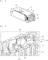
- FIG. 1 is a perspective view showing a battery module according to an embodiment of the present disclosure.
- FIG. 2 is an enlarged perspective view showing a state in which a module connector 130 in a battery module according to an embodiment of the present invention is mounted.
- a battery module 10 includes a module connector 130 mounted outside a module case 150 accommodating a cell assembly 100.
- Battery cells constituting the cell assembly 100 may be provided as a pouch-type secondary battery, and may be provided by stacking a plurality of battery cells in the cell assembly 100.
- the plurality of battery cells may be electrically connected to each other, and each of the battery cells may include an electrode assembly, a battery case accommodating the electrode assembly, and an electrode lead 110 protruding out of the battery case and electrically connected to the electrode assembly.
- the battery module 10 may include various electric components, and may include, for example, an internal circuit board (ICB) and a battery management system (BMS). Electric components such as the ICB and the BMS board may be electrically connected to the plurality of battery cells.
- ICB internal circuit board
- BMS battery management system
- the module case 150 forms the exterior of the battery module 10 and accommodates the cell assembly 100, wherein a busbar assembly 120 may be coupled to at least one side or both sides of the cell assembly 100 positioned in the direction where the electrode leads 110 of the cell assembly 100 extend, and an insulating frame 160 may be coupled to the outside thereof.
- the busbar assembly 120 may include a busbar frame 123 disposed to cover the cell assembly 100, and a busbar fixed to the busbar frame 123.
- the busbar frame 123 is made of an insulator and includes a lead slot through which the electrode leads 110 of the cell assembly 100 can pass.
- the busbar 121 may electrically connect the electrode leads 110 of the cell assembly 100.
- the module connector 130 may be coupled to the busbar assembly 120, particularly the busbar frame 123.
- the module connector 130 has a first fastening part 135 opened in at least one direction on a coupling surface of the lower portion thereof, and the busbar frame 123 has a second fastening part 235 configured on a corresponding coupling surface outside the module case 150 so as to be coupled to the first fastening part 135.
- the first fastening part 135 and the second fastening part 235 may be formed of a slide rail fastening part. In the following, they are referred to as a first slide rail fastening part and a second slide rail fastening part, respectively.
- the present disclosure is not limited to this embodiment, and any module connector having a fastening part with a structure that can be inserted bidirectionally may be included in the scope of the present disclosure.
- the battery module 10 may include a flexible printed circuit (FPC) board 140 configured to sense the battery cells inside the module case 150, and the flexible printed circuit board 140 extends out of the module case 150 and is connected to the module connector 130. Accordingly, the module connector 130 may be electrically connected to the cell assembly 100 via the flexible printed circuit board 140.
- FPC flexible printed circuit
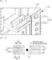
- FIG. 3 is a perspective view showing a module connector of a battery module according to an embodiment of the present disclosure
- FIG. 4 is a bottom view showing a module connector of a battery module according to an embodiment of the present disclosure
- FIG. 5 is an enlarged perspective view showing a fastening part of a busbar assembly in which a module connector of a battery module according to an embodiment of the present disclosure is mounted
- FIG. 6 is a cross-sectional view taken along line VI-VI of FIG. 2 and illustrating a first fastening example of a module connector according to an embodiment of the present disclosure.
- the module connector 130 of the present embodiment has a first slide rail fastening part 135 opened in at least one direction on the coupling surface of the lower portion.
- the corresponding coupling surface outside the module case 150 i.e., the busbar frame 123 of the busbar assembly 120 has a second slide rail fastening part 235 opened bidirectionally. Therefore, the first slide rail fastening part 135 may be coupled to the second slide rail fastening part 235 in a first direction or in a second direction opposite thereto through the opened portion.
- the module connector 130 can be coupled to the busbar assembly 120.
- a first fastening example as shown in FIG.
- the first slide rail fastening part 135 is inserted into the second slide rail fastening part 235 in the first direction (from right to left in FIG. 6 ), so that it can be locked to the corresponding coupling surface outside the module case 150 of FIG. 1 .
- the first slide rail fastening part 135 of the module connector 130 includes three parallel rail members 135a, 135b and 135c
- the second slide rail fastening part 235 of the busbar frame 123 includes two parallel rail members 235a and 235b.
- the inner rail member 135b may be configured to pass between the two rail members 235a and 235b of the second slide rail fastening part 235 and couple thereto.
- the two rail members 235a and 235b of the second slide rail fastening part 235 may have locking protrusions 236 and 237 which protrude in directions opposite to each other, respectively.
- These locking protrusions 236 and 237 may have an inclined surface inclined with respect to the insertion direction of the module connector 130. That is, since the module connector 130 can be inserted into the second slide rail fastening part 235 in the first direction or in the second direction as described above, both the inclined surfaces of the locking protrusions 236 and 237 may be bidirectionally inclined to form an obtuse angle with respect to the extending direction of the rail member.
- the locking protrusions 236 and 237 opposite to each other may be spaced apart at a distance along the extending direction of the rail member so that the respective centers are misaligned with each other.
- inclination angle of the inclined surfaces back to each other may be formed more steeply than that of the inclined surfaces facing each other in the pair of locking protrusions 236 and 237.
- the inclined surfaces facing each other in the pair of locking protrusions 236 and 237 are referred to as inner inclined surfaces 236a and 237a, and the inclined surfaces back to each other (in opposite direction) are referred to as outer inclined surfaces 236b and 237b.
- the outer inclined surfaces 236b and 237b in the pair of locking protrusions 236 and 237 can respectively form a steeper inclined angle with respect to the extending direction of the rail members 235a and 235b than each of the inner inclined surfaces 236a and 237a.
- the inclination angle of the outer inclined surface 236b may be formed more steeply than that of the inner inclined surface 236a
- the inclination angle of the outer inclined surface 237b may be formed more steeply than that of the inner inclined surface 237a.
- the inner rail member 135b of the first slide rail fastening part 135 is a hook-type rail member configured to pass between the two rail members 235a and 235b of the second slide rail fastening part 235 and lock thereto.
- the end of the hook-type rail member includes a hook 136 which is bent to one side, and the other side opposite to the hook 136 may be chamfered. Therefore, when the module connector 130 is coupled, the inner rail member 135b of the first slide rail fastening part 135 passes between the two rail members 235a, 235b of the second slide rail fastening part 235 and, thus, the hook 136 may sequentially pass through two locking protrusions 236 and 237 and be locked.
- the hook 136 may pass though the inner inclined surface 237a of the second locking protrusion 237 located on the left side and then locked to the outer inclined surface 237b of the second locking protrusion 237.
- the inner inclined surface 237a forms a relatively gradual inclination angle and, therefore, is easy for the hook 136 to pass through, and the outer inclined surface 237b forms a relatively steep inclination angle, so the hook 136 can be firmly locked thereto.
- the first slide rail fastening part 135 of the module connector 130 may include two outer rail members 135a and 135c extending in parallel with the inner rail member 135b.
- the rail members 235a and 235b of the second slide rail fastening part 235 may be sandwiched between the outer rail members 135a and 135c of the first slide rail fastening part 135.
- FIG. 7 is a perspective view showing a second fastening example of a module connector according to an embodiment of the present disclosure
- FIG. 8 is a cross-sectional view taken along line VIII-VIII of FIG. 7 and illustrating the second fastening example of a module connector according to an embodiment of the present disclosure.
- the first slide rail fastening part 135 is inserted into the second slide rail fastening part 235 in a second direction (from left to right as viewed in FIG. 8 ), so that the module connector 130 can be locked to the corresponding coupling surface outside the module case 150 of FIG. 1 . That is, as described above, the module connector 130 may be fastened to the second slide rail fastening part 235 formed on the busbar frame 123 via the first slide rail fastening part 135. However, in the second fastening example, it is inserted and fastened from the opposite direction to the first fastening example. In this case, since the flexible printed circuit board 140 extending from the cell assembly 100 is formed to extend while being bent in different directions over a plurality of times, it can be stretched and connected according to the changed direction of the module connector 130.
- the hook 136 passes through the inner inclined surface 236a of the first locking protrusion 236 located on the right side, and then may be locked to the outer inclined surface 236b of the first locking protrusion 236.
- the inner inclined surface 236a forms a relatively gradual inclination angle and, thus, is easy for the hook 136 to pass through, and the outer inclined surface 236b forms a relatively steep inclination angle, so that the hook 136 can be firmly locked thereto.
- outer rail members 135a and 135c of the first slide rail fastening part 135 are defined outside the rail members 235a and 235b of the second slide rail fastening part 235 so that the latter members can be sandwiched between the former members.
- the connector which has a fastening structure in which it can be inserted and coupled bidirectionally, can be applied to a battery module, thereby making it possible to change the direction of the module connector as necessary after production of the battery module.
- the hook 136 of the inner rail member 135b and the pair of locking protrusions 236 and 237 having their respective outer inclined surfaces 236b and 237b forming a steeper inclination angle compared to the inner inclined surfaces 236a and 237a, it is possible to implement both the bidirectional insertion of the module connector 130 and the firm coupling upon insertion.
- one or more of the battery modules according to an embodiment of the present disclosure may be packaged in a pack case to form a battery pack.
- the battery module as described above and the battery pack including the same can be applied to various devices.
- Such devices include, but not limited to, transportation means such as an electric bicycle, an electric vehicle, and a hybrid vehicle, and the present disclosure is applicable to various devices capable of using any battery module and any battery pack including the same, which belongs to the scope of the invention.
Landscapes
- Chemical & Material Sciences (AREA)
- Chemical Kinetics & Catalysis (AREA)
- Electrochemistry (AREA)
- General Chemical & Material Sciences (AREA)
- Engineering & Computer Science (AREA)
- Microelectronics & Electronic Packaging (AREA)
- Manufacturing & Machinery (AREA)
- Aviation & Aerospace Engineering (AREA)
- Battery Mounting, Suspending (AREA)
- Connection Of Batteries Or Terminals (AREA)
Abstract
Description
- This application claims the benefit of priority based on Korean Patent Application No.
10-2018-0155513 filed on December 5, 2018 10-2019-0159240 filed on December 3, 2019 - The present disclosure relates to a battery module, and more particularly, to a battery module in which a module connector connected to an external connector is mounted.
- Secondary batteries, which are easily applied to various product groups and has electrical characteristics such as high energy density, are universally applied not only for a portable device but also for an electric vehicle (EV) or a hybrid electric vehicle (HEV), an energy storage system or the like, which is driven by an electric driving source. The secondary battery is attracting attention as a new environment-friendly energy source for improving energy efficiency since it gives a primary advantage of remarkably reducing the use of fossil fuels and also does not generate by-products from the use of energy at all.
- A battery pack for use in electric vehicles has a structure in which a plurality of cell assemblies, each including a plurality of unit cells, are connected in series to obtain a high output. In addition, the unit cell can be repeatedly charged and discharged by electrochemical reactions among components, which include a positive electrode current collector, a negative electrode current collector, a separator, an active material, an electrolyte and the like.
- Meanwhile, as the need for a large capacity structure is increasing along with the utilization as an energy storage source in recent years, there is a growing demand for a battery pack with a multi-module structure in which a plurality of battery modules, each including a plurality of secondary batteries connected in series and/or in parallel, are integrated.
- When a plurality of battery cells are connected in series or in parallel to configure a battery pack, it is common to configure a battery module composed of at least one battery cell first, and then configure a battery pack by using at least one battery module and adding other components. The number of battery modules included in the battery pack, or the number of battery cells included in the battery module may be variously set according to the required output voltage or the demanded charge/discharge capacity.
- The battery module is configured to package battery cells, various electric components and the like in a module case, and further includes a module connector which is connected to an external connector for electrical connection with external devices, etc. outside the module case. The external connector may be, for example, a connector for electrically connecting a plurality of battery modules.
- In the conventional battery module, the direction of the connector is predetermined for each module. Therefore, there was a need to develop a module with a symmetrical structure according to the predetermined direction of the connector. In this case, all of the same parts were re-developed in a symmetrical form, which resulted in time and cost loss, and increased process complexity.
- Therefore, it is an object of the present disclosure to provide a battery module capable of changing the direction of a module connector as necessary after production of the battery module, by configuring the fastening structure of the module connector mounted on the battery module so that the module connector can be inserted bidirectionally.
- However, the problem to be solved by the embodiments of the present disclosure is not limited to the above-described problems, and can be variously expanded within the scope of the technical idea included in the present disclosure.
- A battery module according to an embodiment of the present disclosure includes: a cell assembly including at least one battery cell; a module case accommodating the cell assembly; and a module connector mounted outside the module case, electrically connected to the cell assembly, and connected to an external connector outside the module case. A coupling surface of the module connector may have a first fastening part opened in at least one direction, and a corresponding coupling surface outside the module case may have a second fastening part that is bidirectionally opened so as to be inserted into the first fastening part in a first direction or in a second direction opposite thereto.
- The first fastening part may be a first slide rail fastening part, and the second fastening part may be a second slide rail fastening part, wherein the first slide rail fastening part and the second slide rail fastening part may be slidably coupled to each other.
- The second slide rail fastening part may include at least two parallel rail members, and the first slide rail fastening part may include an inner rail member configured to pass between the two rail members of the second slide rail fastening part and couple thereto.
- The two rail members of the second slide rail fastening part may have the respective locking protrusions which protrude in directions opposite to each other.
- The respective locking protrusions of the two rail members may be spaced apart at a distance along an extending direction of the rail member so that the respective centers are misaligned with each other.
- The locking protrusions may have an inclined surface inclined to form an obtuse angle with respect to an insertion direction of the module connector.
- The inner rail member of the first slide rail fastening part may include a hook configured to pass between the two rail members of the second slide rail fastening part and couple thereto.
- The two rail members of the second slide rail fastening part may have a first locking protrusion and a second locking protrusion, which protrude in directions opposite to each other, wherein the first locking protrusion and the second locking protrusion may be spaced apart at a distance along an extending direction of the rail member so that respective centers are misaligned with each other, the first locking protrusion may be positioned on relatively right side, and the second locking protrusion may be positioned on relatively left side.
- Each of the outer inclined surfaces of the first locking protrusion and the second locking protrusion back to each other may form a steeper inclination angle with respect to the extending direction of the rail member than each of the inner inclined surfaces of the first locking protrusion and the second locking protrusion facing each other.
- The hook may be bent to one side at the end of the inner rail member, and when the first fastening part is inserted into the second fastening part in the first direction, the hook may be locked to the outer inclined surface of the second locking protrusion. When the first fastening part is inserted into the second fastening part in the second direction, the hook may be locked to the outer inclined surface of the first locking protrusion.
- The first slide rail fastening part includes at least two outer rail members extending in parallel with the inner rail member, and when the module connector is coupled, the rail member of the second slide rail fastening part may be sandwiched between the outer rail members of the first slide rail fastening part.
- The module connector may be locked to the corresponding coupling surface outside the module case by inserting the first fastening part into the second fastening part in the first direction.
- The module connector may be locked to the corresponding coupling surface outside the module case by inserting the first fastening part into the second fastening part in the second direction.
- The battery module may include a busbar assembly which covers the cell assembly on at least one side of the module case and electrically connects the electrode leads of the cell assembly, wherein the busbar assembly includes the second fastening part, and the module connector may be coupled to the busbar assembly.
- The module connector may be electrically connected to the cell assembly through a flexible printed circuit (FPC) board.
- The flexible printed circuit board connected to the module connector may extend while being bent in different directions over a plurality of times.
- According to another embodiment of the present disclosure, there can be provided a battery pack including at least one of the above battery modules and a pack case packaging the at least one battery module.
- According to still another embodiment of the present disclosure, there can be provided a device including at least one of the battery pack.
- According to the embodiments, a module connector having a fastening structure capable of being inserted and coupled bidirectionally can be applied to a battery module, thereby making it possible to change the direction of the module connector as necessary after production of the battery module.
-
-
FIG. 1 is a perspective view showing a battery module according to an embodiment of the present disclosure. -
FIG. 2 is an enlarged perspective view showing a state in which a module connector in a battery module according to an embodiment of the present disclosure is mounted. -
FIG. 3 is a perspective view showing a module connector of a battery module according to an embodiment of the present disclosure. -
FIG. 4 is a bottom view showing a module connector of a battery module according to an embodiment of the present disclosure. -
FIG. 5 is an enlarged perspective view showing a fastening part of a busbar assembly in which a module connector of a battery module according to an embodiment of the present disclosure is mounted. -
FIG. 6 is a cross-sectional view taken along line VI-VI ofFIG. 2 and illustrating a first fastening example of a module connector according to an embodiment of the present disclosure. -
FIG. 7 is a perspective view showing a second fastening example of a module connector according to an embodiment of the present disclosure. -
FIG. 8 is a cross-sectional view taken along line VIII-VIII ofFIG. 7 and illustrating a second fastening example of a module connector according to an embodiment of the present disclosure. - Hereinafter, various embodiments of the present disclosure will be described in detail with reference to the accompanying drawings so that those skilled in the art can easily implement them. The present disclosure may be modified in various different ways, and is not limited to the embodiments set forth herein.
- Further, throughout the specification, when a part is referred to as "including" a certain component, it means that it can further include other components, without excluding the other components, unless otherwise stated.
- Further, throughout the specification, when referred to as "planar", it means when a target portion is viewed from the top, and when referred to as "cross-sectional", it means when a target portion is viewed from the side of a cross section cut vertically.
-
FIG. 1 is a perspective view showing a battery module according to an embodiment of the present disclosure.FIG. 2 is an enlarged perspective view showing a state in which amodule connector 130 in a battery module according to an embodiment of the present invention is mounted. - Referring to
FIGS. 1 and 2 , abattery module 10 according to the present embodiment includes amodule connector 130 mounted outside amodule case 150 accommodating acell assembly 100. Battery cells constituting thecell assembly 100 may be provided as a pouch-type secondary battery, and may be provided by stacking a plurality of battery cells in thecell assembly 100. The plurality of battery cells may be electrically connected to each other, and each of the battery cells may include an electrode assembly, a battery case accommodating the electrode assembly, and anelectrode lead 110 protruding out of the battery case and electrically connected to the electrode assembly. - The
battery module 10 may include various electric components, and may include, for example, an internal circuit board (ICB) and a battery management system (BMS). Electric components such as the ICB and the BMS board may be electrically connected to the plurality of battery cells. - The
module case 150 forms the exterior of thebattery module 10 and accommodates thecell assembly 100, wherein abusbar assembly 120 may be coupled to at least one side or both sides of thecell assembly 100 positioned in the direction where the electrode leads 110 of thecell assembly 100 extend, and aninsulating frame 160 may be coupled to the outside thereof. Thebusbar assembly 120 may include abusbar frame 123 disposed to cover thecell assembly 100, and a busbar fixed to thebusbar frame 123. Thebusbar frame 123 is made of an insulator and includes a lead slot through which the electrode leads 110 of thecell assembly 100 can pass. Thebusbar 121 may electrically connect the electrode leads 110 of thecell assembly 100. - Referring to
FIG. 2 , themodule connector 130 may be coupled to thebusbar assembly 120, particularly thebusbar frame 123. Themodule connector 130 has afirst fastening part 135 opened in at least one direction on a coupling surface of the lower portion thereof, and thebusbar frame 123 has asecond fastening part 235 configured on a corresponding coupling surface outside themodule case 150 so as to be coupled to thefirst fastening part 135. In this embodiment, thefirst fastening part 135 and thesecond fastening part 235 may be formed of a slide rail fastening part. In the following, they are referred to as a first slide rail fastening part and a second slide rail fastening part, respectively. However, the present disclosure is not limited to this embodiment, and any module connector having a fastening part with a structure that can be inserted bidirectionally may be included in the scope of the present disclosure. - Meanwhile, the
battery module 10 may include a flexible printed circuit (FPC)board 140 configured to sense the battery cells inside themodule case 150, and the flexible printedcircuit board 140 extends out of themodule case 150 and is connected to themodule connector 130. Accordingly, themodule connector 130 may be electrically connected to thecell assembly 100 via the flexible printedcircuit board 140. In addition, since the flexible printedcircuit board 140 is formed to extend while being bent in different directions over a plurality of times, the degree of freedom in the fastening process may be increased. -
FIG. 3 is a perspective view showing a module connector of a battery module according to an embodiment of the present disclosure,FIG. 4 is a bottom view showing a module connector of a battery module according to an embodiment of the present disclosure,FIG. 5 is an enlarged perspective view showing a fastening part of a busbar assembly in which a module connector of a battery module according to an embodiment of the present disclosure is mounted, andFIG. 6 is a cross-sectional view taken along line VI-VI ofFIG. 2 and illustrating a first fastening example of a module connector according to an embodiment of the present disclosure. - Referring to
FIGS. 3 and 4 , themodule connector 130 of the present embodiment has a first sliderail fastening part 135 opened in at least one direction on the coupling surface of the lower portion. Referring toFIG. 5 , the corresponding coupling surface outside themodule case 150, i.e., thebusbar frame 123 of thebusbar assembly 120 has a second sliderail fastening part 235 opened bidirectionally. Therefore, the first sliderail fastening part 135 may be coupled to the second sliderail fastening part 235 in a first direction or in a second direction opposite thereto through the opened portion. Thus, themodule connector 130 can be coupled to thebusbar assembly 120. In a first fastening example, as shown inFIG. 6 , the first sliderail fastening part 135 is inserted into the second sliderail fastening part 235 in the first direction (from right to left inFIG. 6 ), so that it can be locked to the corresponding coupling surface outside themodule case 150 ofFIG. 1 . - The first slide
rail fastening part 135 of themodule connector 130 includes threeparallel rail members rail fastening part 235 of thebusbar frame 123 includes twoparallel rail members rail members rail fastening part 135, theinner rail member 135b may be configured to pass between the tworail members rail fastening part 235 and couple thereto. - The two
rail members rail fastening part 235 may have lockingprotrusions protrusions module connector 130. That is, since themodule connector 130 can be inserted into the second sliderail fastening part 235 in the first direction or in the second direction as described above, both the inclined surfaces of the lockingprotrusions protrusions protrusions protrusions inclined surfaces inclined surfaces inclined surfaces protrusions rail members inclined surfaces - Specifically, in the first locking
protrusions 236 positioned relatively on the right side among the lockingprotrusions inclined surface 236b may be formed more steeply than that of the innerinclined surface 236a, and in the second lockingprotrusions 237 positioned relatively on the left side among the lockingprotrusions inclined surface 237b may be formed more steeply than that of the innerinclined surface 237a. - Meanwhile, the
inner rail member 135b of the first sliderail fastening part 135 is a hook-type rail member configured to pass between the tworail members rail fastening part 235 and lock thereto. The end of the hook-type rail member includes ahook 136 which is bent to one side, and the other side opposite to thehook 136 may be chamfered. Therefore, when themodule connector 130 is coupled, theinner rail member 135b of the first sliderail fastening part 135 passes between the tworail members rail fastening part 235 and, thus, thehook 136 may sequentially pass through two lockingprotrusions - Specifically, when the first slide
rail fastening part 135 is inserted in the first direction (from right to left as viewed inFIG. 6 ), thehook 136 may pass though the innerinclined surface 237a of thesecond locking protrusion 237 located on the left side and then locked to the outerinclined surface 237b of thesecond locking protrusion 237. The innerinclined surface 237a forms a relatively gradual inclination angle and, therefore, is easy for thehook 136 to pass through, and the outerinclined surface 237b forms a relatively steep inclination angle, so thehook 136 can be firmly locked thereto. - In addition, since the side opposite to the
hook 136 is chamfered, it can easily pass through the outerinclined surface 236b of thefirst locking protrusion 236 located on the right side. - The first slide
rail fastening part 135 of themodule connector 130 may include twoouter rail members inner rail member 135b. When themodule connector 130 is coupled, therail members rail fastening part 235 may be sandwiched between theouter rail members rail fastening part 135. -
FIG. 7 is a perspective view showing a second fastening example of a module connector according to an embodiment of the present disclosure, andFIG. 8 is a cross-sectional view taken along line VIII-VIII ofFIG. 7 and illustrating the second fastening example of a module connector according to an embodiment of the present disclosure. - Referring to
FIGS. 7 and 8 , the first sliderail fastening part 135 is inserted into the second sliderail fastening part 235 in a second direction (from left to right as viewed inFIG. 8 ), so that themodule connector 130 can be locked to the corresponding coupling surface outside themodule case 150 ofFIG. 1 . That is, as described above, themodule connector 130 may be fastened to the second sliderail fastening part 235 formed on thebusbar frame 123 via the first sliderail fastening part 135. However, in the second fastening example, it is inserted and fastened from the opposite direction to the first fastening example. In this case, since the flexible printedcircuit board 140 extending from thecell assembly 100 is formed to extend while being bent in different directions over a plurality of times, it can be stretched and connected according to the changed direction of themodule connector 130. - In addition, even when the
hook 136 of theinner rail member 135b of the first sliderail fastening part 135 formed in themodule case 150 is inserted in the second direction, it may be locked by sequentially passing through two lockingprotrusions rail members rail fastening part 235. - Specifically, when the first slide
rail fastening part 135 is inserted in the second direction (from left to right as viewed inFIG. 8 ), thehook 136 passes through the innerinclined surface 236a of thefirst locking protrusion 236 located on the right side, and then may be locked to the outerinclined surface 236b of thefirst locking protrusion 236. The innerinclined surface 236a forms a relatively gradual inclination angle and, thus, is easy for thehook 136 to pass through, and the outerinclined surface 236b forms a relatively steep inclination angle, so that thehook 136 can be firmly locked thereto. - Moreover, since the side opposite to the
hook 136 is chamfered, it can easily pass through the outerinclined surface 237b of thesecond locking protrusion 237 located on the left side. - In addition, the
outer rail members rail fastening part 135 are defined outside therail members rail fastening part 235 so that the latter members can be sandwiched between the former members. - Thus, according to the embodiment of the present disclosure, the connector, which has a fastening structure in which it can be inserted and coupled bidirectionally, can be applied to a battery module, thereby making it possible to change the direction of the module connector as necessary after production of the battery module. In particular, as described above, through the
hook 136 of theinner rail member 135b and the pair of lockingprotrusions inclined surfaces inclined surfaces module connector 130 and the firm coupling upon insertion. - Meanwhile, one or more of the battery modules according to an embodiment of the present disclosure may be packaged in a pack case to form a battery pack.
- The battery module as described above and the battery pack including the same can be applied to various devices. Such devices include, but not limited to, transportation means such as an electric bicycle, an electric vehicle, and a hybrid vehicle, and the present disclosure is applicable to various devices capable of using any battery module and any battery pack including the same, which belongs to the scope of the invention.
- Although the preferred embodiments of the present disclosure have been described in detail above, the scope of the present disclosure is not limited thereto, and various modifications and improvements of those skilled in the art using the basic concepts of the present disclosure defined in the following claims also belong to the scope of rights.
-
- 10:
- battery module
- 100:
- cell assembly
- 110:
- electrode lead
- 120:
- busbar assembly
- 121:
- busbar
- 123:
- busbar frame
- 130:
- module connector
- 135:
- first slide fastening part
- 135a, 135c:
- outer rail member of first slide fastening part
- 135b:
- inner rail member of first slide fastening part
- 136:
- hook
- 140:
- flexible printed circuit board
- 150:
- module case
- 235:
- second slide rail fastening part
- 235a, 235b:
- rail member of the second slide rail fastening part
- 236, 237:
- locking protrusion
Claims (18)
- A battery module comprising:a cell assembly including at least one battery cell;a module case accommodating the cell assembly; anda module connector mounted outside the module case, electrically connected to the cell assembly, and connected to an external connector outside the module case,wherein a coupling surface of the module connector has a first fastening part opened in at least one direction, and a corresponding coupling surface outside the module case has a second fastening part opened bidirectionally so as to be inserted into the first fastening part in a first direction or in a second direction opposite thereto.
- The battery module of claim 1, wherein the first fastening part is a first slide rail fastening part,
the second fastening part is a second slide rail fastening part, and
the first slide rail fastening part and the second slide rail fastening part are slidably coupled to each other. - The battery module of claim 2, wherein the second slide rail fastening part includes at least two parallel rail members, and
the first slide rail fastening part includes an inner rail member configured to pass between two rail members of the second slide rail fastening part and couple thereto. - The battery module of claim 3, wherein the two rail members of the second slide rail fastening part have respective locking protrusions which protrude in directions opposite to each other.
- The battery module of claim 4, wherein the respective locking protrusions of the two rail members are spaced apart at a distance along an extending direction of the rail member so that the respective centers are misaligned with each other.
- The battery module of claim 4, wherein the locking protrusions have an inclined surface inclined to form an obtuse angle with respect to an insertion direction of the module connector.
- The battery module of claim 3, wherein the inner rail member of the first slide rail fastening part includes a hook configured to pass between the two rail members of the second slide rail fastening part and couple thereto.
- The battery module of claim 7, wherein the two rail members of the second slide rail fastening part have a first locking protrusion and a second locking protrusion, which protrude in directions opposite to each other,
the first locking protrusion and the second locking protrusion are spaced apart at a distance along an extending direction of the rail member so that the respective centers are misaligned with each other, the first locking protrusion is positioned on relatively right side, and the second locking protrusion is positioned on relatively left side. - The battery module of claim 8, wherein each of the outer inclined surfaces of the first locking protrusion and the second locking protrusion back to each other forms a steeper inclination angle with respect to the extending direction of the rail member than each of the inner inclined surfaces of the first locking protrusion and the second locking protrusion facing each other.
- The battery module of claim 9, wherein
the hook is bent to one side at the end of the inner rail member,
when the first fastening part is inserted into the second fastening part in the first direction, the hook is locked to the outer inclined surface of the second locking protrusion, and
when the first fastening part is inserted into the second fastening part in the second direction, the hook is locked to the outer inclined surface of the first locking protrusion. - The battery module of claim 3, wherein the first slide rail fastening part includes at least two outer rail members extending in parallel with the inner rail member, and
when the module connector is coupled, the rail member of the second slide rail fastening part is sandwiched between the outer rail members of the first slide rail fastening part. - The battery module of claim 1, wherein the module connector is locked to the corresponding coupling surface outside the module case by inserting the first fastening part into the second fastening part in the first direction.
- The battery module of claim 1, wherein the module connector is locked to the corresponding coupling surface outside the module case by inserting the first fastening part into the second fastening part in the second direction.
- The battery module of claim 1, comprising a busbar assembly which covers the cell assembly on at least one side of the module case and electrically connects the electrode leads of the cell assembly, wherein the busbar assembly includes the second fastening part, and the module connector is coupled to the busbar assembly.
- The battery module of claim 1, wherein the module connector is electrically connected to the cell assembly via a flexible printed circuit (FPC) board.
- The battery module of claim 15, wherein the flexible printed circuit board connected to the module connector extends while being bent in different directions over a plurality of times.
- A battery pack comprising:at least one of the battery modules according to any one of claims 1 to 16; anda pack case packaging the at least one battery module.
- A device comprising at least one of the battery pack according to claim 17.
Applications Claiming Priority (3)
| Application Number | Priority Date | Filing Date | Title |
|---|---|---|---|
| KR20180155513 | 2018-12-05 | ||
| KR1020190159240A KR102321794B1 (en) | 2018-12-05 | 2019-12-03 | Battery module including connector having bidirectional coupling structure |
| PCT/KR2019/017024 WO2020116936A1 (en) | 2018-12-05 | 2019-12-04 | Battery module comprising connector having bidirectional fastening structure |
Publications (3)
| Publication Number | Publication Date |
|---|---|
| EP3764421A1 true EP3764421A1 (en) | 2021-01-13 |
| EP3764421A4 EP3764421A4 (en) | 2021-05-12 |
| EP3764421B1 EP3764421B1 (en) | 2025-06-25 |
Family
ID=71081781
Family Applications (1)
| Application Number | Title | Priority Date | Filing Date |
|---|---|---|---|
| EP19891755.1A Active EP3764421B1 (en) | 2018-12-05 | 2019-12-04 | Battery module including connector having bidirectional coupling structure |
Country Status (7)
| Country | Link |
|---|---|
| US (1) | US11894576B2 (en) |
| EP (1) | EP3764421B1 (en) |
| JP (1) | JP7055483B2 (en) |
| KR (1) | KR102321794B1 (en) |
| CN (1) | CN111971817B (en) |
| ES (1) | ES3036868T3 (en) |
| HU (1) | HUE072210T2 (en) |
Cited By (1)
| Publication number | Priority date | Publication date | Assignee | Title |
|---|---|---|---|---|
| EP4262007A3 (en) * | 2022-04-14 | 2024-02-28 | Sungrow Energy Storage Technology Co., Ltd. | Energy storage system |
Families Citing this family (2)
| Publication number | Priority date | Publication date | Assignee | Title |
|---|---|---|---|---|
| KR102857910B1 (en) * | 2021-05-11 | 2025-09-09 | 주식회사 엘지에너지솔루션 | Battery module and battery pack including the same |
| KR20220161057A (en) | 2021-05-28 | 2022-12-06 | 주식회사 엘지에너지솔루션 | Battery module and battery pack including the same |
Family Cites Families (23)
| Publication number | Priority date | Publication date | Assignee | Title |
|---|---|---|---|---|
| JP2837085B2 (en) | 1993-08-06 | 1998-12-14 | 矢崎総業株式会社 | Connector locking structure |
| JP2001160450A (en) | 1999-12-02 | 2001-06-12 | Sumitomo Wiring Syst Ltd | Connector joints |
| ATE389960T1 (en) | 2004-06-30 | 2008-04-15 | Tyco Electronics Nederland Bv | CONNECTORS FOR ELECTRONIC COMPONENTS |
| JP5582815B2 (en) * | 2010-02-18 | 2014-09-03 | 日本航空電子工業株式会社 | Battery connection device |
| US9005794B2 (en) | 2011-10-21 | 2015-04-14 | Tyco Electronics Corporation | Battery connector system |
| US20130260611A1 (en) | 2012-04-03 | 2013-10-03 | Jang-Gun Ahn | Battery module |
| US20140014164A1 (en) | 2012-07-12 | 2014-01-16 | Samsung Sdi Co., Ltd. | Connecting structure of solar cell modules |
| KR101384636B1 (en) | 2012-08-27 | 2014-04-14 | 인지컨트롤스 주식회사 | Sensing module for secondary battery |
| KR102025947B1 (en) | 2012-12-27 | 2019-09-26 | 타이코에이엠피 주식회사 | Protection circuit module and battery module including the same |
| JP6039490B2 (en) | 2013-04-16 | 2016-12-07 | 日本航空電子工業株式会社 | Connector and battery pack |
| US10249916B2 (en) | 2015-04-13 | 2019-04-02 | Johnson Controls Technology Company | Connector barrel for a battery module |
| KR101875538B1 (en) | 2015-04-22 | 2018-07-06 | 주식회사 엘지화학 | Battery Module Comprising Molding Part for Insulating PCB |
| KR101953362B1 (en) * | 2015-09-02 | 2019-05-22 | 주식회사 엘지화학 | Battery Module having an improved coupling structure |
| CN205810940U (en) * | 2016-05-20 | 2016-12-14 | 莫列斯有限公司 | Conflux connector and battery connection module |
| KR102034206B1 (en) | 2016-07-26 | 2019-10-18 | 주식회사 엘지화학 | Battery module and battery pack including the same |
| US10543795B2 (en) | 2016-09-02 | 2020-01-28 | Cps Technology Holdings Llc | Battery module connector barrel |
| US10749161B2 (en) * | 2016-09-23 | 2020-08-18 | Artisan Vehicle Systems Inc. | Unified connection array for battery module |
| JP6560179B2 (en) | 2016-10-17 | 2019-08-14 | 矢崎総業株式会社 | Busbar module |
| KR102018720B1 (en) | 2016-11-29 | 2019-09-04 | 주식회사 엘지화학 | Battery module with structure for mounting sensing connector |
| KR101829350B1 (en) | 2016-12-30 | 2018-02-14 | 한국단자공업 주식회사 | Sensing apparatus for battery module |
| CN108321318B (en) * | 2017-01-17 | 2021-03-09 | 莫列斯有限公司 | Battery connection module and battery device |
| CN206451944U (en) * | 2017-02-15 | 2017-08-29 | 宁德时代新能源科技股份有限公司 | Connector fixing construction and battery modules |
| CN207381657U (en) | 2017-10-26 | 2018-05-18 | 宁德时代新能源科技股份有限公司 | Battery module connector and battery module |
-
2019
- 2019-12-03 KR KR1020190159240A patent/KR102321794B1/en active Active
- 2019-12-04 EP EP19891755.1A patent/EP3764421B1/en active Active
- 2019-12-04 HU HUE19891755A patent/HUE072210T2/en unknown
- 2019-12-04 CN CN201980025814.1A patent/CN111971817B/en active Active
- 2019-12-04 US US17/044,997 patent/US11894576B2/en active Active
- 2019-12-04 JP JP2020552230A patent/JP7055483B2/en active Active
- 2019-12-04 ES ES19891755T patent/ES3036868T3/en active Active
Cited By (1)
| Publication number | Priority date | Publication date | Assignee | Title |
|---|---|---|---|---|
| EP4262007A3 (en) * | 2022-04-14 | 2024-02-28 | Sungrow Energy Storage Technology Co., Ltd. | Energy storage system |
Also Published As
| Publication number | Publication date |
|---|---|
| HUE072210T2 (en) | 2025-10-28 |
| EP3764421B1 (en) | 2025-06-25 |
| US11894576B2 (en) | 2024-02-06 |
| JP7055483B2 (en) | 2022-04-18 |
| KR20200068593A (en) | 2020-06-15 |
| US20210167466A1 (en) | 2021-06-03 |
| CN111971817A (en) | 2020-11-20 |
| ES3036868T3 (en) | 2025-09-25 |
| KR102321794B1 (en) | 2021-11-04 |
| EP3764421A4 (en) | 2021-05-12 |
| CN111971817B (en) | 2022-12-16 |
| JP2021517720A (en) | 2021-07-26 |
Similar Documents
| Publication | Publication Date | Title |
|---|---|---|
| US11996585B2 (en) | Battery module including terminal connecting structure provided with floating nut and battery pack including the same | |
| US11196120B2 (en) | Battery module, and battery pack and vehicle comprising same | |
| US20210313657A1 (en) | Battery Module with ICB Assembly in Space-Saving Structure | |
| EP3761396B1 (en) | Battery module including protective cover for covering flexible printed circuit board | |
| US11018391B2 (en) | Battery cell, battery module, and battery pack and vehicle including the same | |
| US11967735B2 (en) | Battery module | |
| EP4199208B1 (en) | Battery pack | |
| US12500304B2 (en) | Battery module including connector having shock absorbing structure | |
| EP3783693B1 (en) | Battery module, battery pack comprising same battery module, and vehicle comprising same battery pack | |
| KR102853166B1 (en) | Baettery module, battery pack and vehicle comprising the battery module | |
| EP4030515B1 (en) | Battery module | |
| KR20200100408A (en) | Battery cell, battery module comprising the battery cell, battery rack comprising the battery module and energy storage system comprising the battery rack | |
| US11894576B2 (en) | Battery module including connector having bidirectional coupling structure | |
| EP3930028B1 (en) | Battery module | |
| US20250030099A1 (en) | Logical Cell, Secondary Battery Module and Secondary Pack Including the Same | |
| KR20230097897A (en) | Logical cell, secondary battery module and secondary battery pack including the same | |
| EP4708508A1 (en) | Battery pack and vehicle including same | |
| US20260106332A1 (en) | Busbar assembly | |
| KR102165018B1 (en) | Battery module, battery pack comprising the battery module and vehicle comprising the battery pack | |
| CN120615253A (en) | Battery module including bus bar assembly and battery pack including the same | |
| KR20230082198A (en) | Battery module assembly |
Legal Events
| Date | Code | Title | Description |
|---|---|---|---|
| STAA | Information on the status of an ep patent application or granted ep patent |
Free format text: STATUS: THE INTERNATIONAL PUBLICATION HAS BEEN MADE |
|
| PUAI | Public reference made under article 153(3) epc to a published international application that has entered the european phase |
Free format text: ORIGINAL CODE: 0009012 |
|
| STAA | Information on the status of an ep patent application or granted ep patent |
Free format text: STATUS: REQUEST FOR EXAMINATION WAS MADE |
|
| 17P | Request for examination filed |
Effective date: 20201007 |
|
| AK | Designated contracting states |
Kind code of ref document: A1 Designated state(s): AL AT BE BG CH CY CZ DE DK EE ES FI FR GB GR HR HU IE IS IT LI LT LU LV MC MK MT NL NO PL PT RO RS SE SI SK SM TR |
|
| AX | Request for extension of the european patent |
Extension state: BA ME |
|
| REG | Reference to a national code |
Ref country code: DE Ref legal event code: R079 Ipc: H01M0010420000 Ref country code: DE Ref legal event code: R079 Ref document number: 602019071745 Country of ref document: DE Free format text: PREVIOUS MAIN CLASS: H01M0002100000 Ipc: H01M0010420000 |
|
| A4 | Supplementary search report drawn up and despatched |
Effective date: 20210413 |
|
| RIC1 | Information provided on ipc code assigned before grant |
Ipc: H01M 10/42 20060101AFI20210407BHEP Ipc: H01M 50/543 20210101ALI20210407BHEP |
|
| RAP1 | Party data changed (applicant data changed or rights of an application transferred) |
Owner name: LG ENERGY SOLUTION LTD. |
|
| DAV | Request for validation of the european patent (deleted) | ||
| DAX | Request for extension of the european patent (deleted) | ||
| RAP3 | Party data changed (applicant data changed or rights of an application transferred) |
Owner name: LG ENERGY SOLUTION, LTD. |
|
| STAA | Information on the status of an ep patent application or granted ep patent |
Free format text: STATUS: EXAMINATION IS IN PROGRESS |
|
| 17Q | First examination report despatched |
Effective date: 20221220 |
|
| GRAP | Despatch of communication of intention to grant a patent |
Free format text: ORIGINAL CODE: EPIDOSNIGR1 |
|
| STAA | Information on the status of an ep patent application or granted ep patent |
Free format text: STATUS: GRANT OF PATENT IS INTENDED |
|
| INTG | Intention to grant announced |
Effective date: 20250225 |
|
| GRAS | Grant fee paid |
Free format text: ORIGINAL CODE: EPIDOSNIGR3 |
|
| GRAA | (expected) grant |
Free format text: ORIGINAL CODE: 0009210 |
|
| STAA | Information on the status of an ep patent application or granted ep patent |
Free format text: STATUS: THE PATENT HAS BEEN GRANTED |
|
| AK | Designated contracting states |
Kind code of ref document: B1 Designated state(s): AL AT BE BG CH CY CZ DE DK EE ES FI FR GB GR HR HU IE IS IT LI LT LU LV MC MK MT NL NO PL PT RO RS SE SI SK SM TR |
|
| REG | Reference to a national code |
Ref country code: GB Ref legal event code: FG4D |
|
| REG | Reference to a national code |
Ref country code: CH Ref legal event code: EP |
|
| REG | Reference to a national code |
Ref country code: DE Ref legal event code: R096 Ref document number: 602019071745 Country of ref document: DE |
|
| REG | Reference to a national code |
Ref country code: CH Ref legal event code: EP |
|
| P01 | Opt-out of the competence of the unified patent court (upc) registered |
Free format text: CASE NUMBER: APP_27148/2025 Effective date: 20250606 |
|
| REG | Reference to a national code |
Ref country code: IE Ref legal event code: FG4D |
|
| REG | Reference to a national code |
Ref country code: ES Ref legal event code: FG2A Ref document number: 3036868 Country of ref document: ES Kind code of ref document: T3 Effective date: 20250925 |
|
| PG25 | Lapsed in a contracting state [announced via postgrant information from national office to epo] |
Ref country code: FI Free format text: LAPSE BECAUSE OF FAILURE TO SUBMIT A TRANSLATION OF THE DESCRIPTION OR TO PAY THE FEE WITHIN THE PRESCRIBED TIME-LIMIT Effective date: 20250625 |
|
| REG | Reference to a national code |
Ref country code: LT Ref legal event code: MG9D |
|
| PG25 | Lapsed in a contracting state [announced via postgrant information from national office to epo] |
Ref country code: NO Free format text: LAPSE BECAUSE OF FAILURE TO SUBMIT A TRANSLATION OF THE DESCRIPTION OR TO PAY THE FEE WITHIN THE PRESCRIBED TIME-LIMIT Effective date: 20250925 Ref country code: GR Free format text: LAPSE BECAUSE OF FAILURE TO SUBMIT A TRANSLATION OF THE DESCRIPTION OR TO PAY THE FEE WITHIN THE PRESCRIBED TIME-LIMIT Effective date: 20250926 |
|
| PG25 | Lapsed in a contracting state [announced via postgrant information from national office to epo] |
Ref country code: BG Free format text: LAPSE BECAUSE OF FAILURE TO SUBMIT A TRANSLATION OF THE DESCRIPTION OR TO PAY THE FEE WITHIN THE PRESCRIBED TIME-LIMIT Effective date: 20250625 |
|
| PG25 | Lapsed in a contracting state [announced via postgrant information from national office to epo] |
Ref country code: HR Free format text: LAPSE BECAUSE OF FAILURE TO SUBMIT A TRANSLATION OF THE DESCRIPTION OR TO PAY THE FEE WITHIN THE PRESCRIBED TIME-LIMIT Effective date: 20250625 |
|
| PG25 | Lapsed in a contracting state [announced via postgrant information from national office to epo] |
Ref country code: RS Free format text: LAPSE BECAUSE OF FAILURE TO SUBMIT A TRANSLATION OF THE DESCRIPTION OR TO PAY THE FEE WITHIN THE PRESCRIBED TIME-LIMIT Effective date: 20250925 |
|
| REG | Reference to a national code |
Ref country code: HU Ref legal event code: AG4A Ref document number: E072210 Country of ref document: HU |
|
| PG25 | Lapsed in a contracting state [announced via postgrant information from national office to epo] |
Ref country code: LV Free format text: LAPSE BECAUSE OF FAILURE TO SUBMIT A TRANSLATION OF THE DESCRIPTION OR TO PAY THE FEE WITHIN THE PRESCRIBED TIME-LIMIT Effective date: 20250625 |
|
| REG | Reference to a national code |
Ref country code: NL Ref legal event code: MP Effective date: 20250625 |
|
| PG25 | Lapsed in a contracting state [announced via postgrant information from national office to epo] |
Ref country code: NL Free format text: LAPSE BECAUSE OF FAILURE TO SUBMIT A TRANSLATION OF THE DESCRIPTION OR TO PAY THE FEE WITHIN THE PRESCRIBED TIME-LIMIT Effective date: 20250625 |
|
| PG25 | Lapsed in a contracting state [announced via postgrant information from national office to epo] |
Ref country code: PT Free format text: LAPSE BECAUSE OF FAILURE TO SUBMIT A TRANSLATION OF THE DESCRIPTION OR TO PAY THE FEE WITHIN THE PRESCRIBED TIME-LIMIT Effective date: 20251027 |
|
| REG | Reference to a national code |
Ref country code: AT Ref legal event code: MK05 Ref document number: 1807534 Country of ref document: AT Kind code of ref document: T Effective date: 20250625 |
|
| PG25 | Lapsed in a contracting state [announced via postgrant information from national office to epo] |
Ref country code: IS Free format text: LAPSE BECAUSE OF FAILURE TO SUBMIT A TRANSLATION OF THE DESCRIPTION OR TO PAY THE FEE WITHIN THE PRESCRIBED TIME-LIMIT Effective date: 20251025 |
|
| PGFP | Annual fee paid to national office [announced via postgrant information from national office to epo] |
Ref country code: DE Payment date: 20251120 Year of fee payment: 7 |
|
| PGFP | Annual fee paid to national office [announced via postgrant information from national office to epo] |
Ref country code: GB Payment date: 20251120 Year of fee payment: 7 |
|
| PG25 | Lapsed in a contracting state [announced via postgrant information from national office to epo] |
Ref country code: AT Free format text: LAPSE BECAUSE OF FAILURE TO SUBMIT A TRANSLATION OF THE DESCRIPTION OR TO PAY THE FEE WITHIN THE PRESCRIBED TIME-LIMIT Effective date: 20250625 Ref country code: SM Free format text: LAPSE BECAUSE OF FAILURE TO SUBMIT A TRANSLATION OF THE DESCRIPTION OR TO PAY THE FEE WITHIN THE PRESCRIBED TIME-LIMIT Effective date: 20250625 |
|
| PGFP | Annual fee paid to national office [announced via postgrant information from national office to epo] |
Ref country code: HU Payment date: 20251216 Year of fee payment: 7 Ref country code: FR Payment date: 20251125 Year of fee payment: 7 |
|
| PGFP | Annual fee paid to national office [announced via postgrant information from national office to epo] |
Ref country code: BE Payment date: 20251120 Year of fee payment: 7 |
|
| PG25 | Lapsed in a contracting state [announced via postgrant information from national office to epo] |
Ref country code: CZ Free format text: LAPSE BECAUSE OF FAILURE TO SUBMIT A TRANSLATION OF THE DESCRIPTION OR TO PAY THE FEE WITHIN THE PRESCRIBED TIME-LIMIT Effective date: 20250625 |
|
| PG25 | Lapsed in a contracting state [announced via postgrant information from national office to epo] |
Ref country code: PL Free format text: LAPSE BECAUSE OF FAILURE TO SUBMIT A TRANSLATION OF THE DESCRIPTION OR TO PAY THE FEE WITHIN THE PRESCRIBED TIME-LIMIT Effective date: 20250625 |
|
| PG25 | Lapsed in a contracting state [announced via postgrant information from national office to epo] |
Ref country code: EE Free format text: LAPSE BECAUSE OF FAILURE TO SUBMIT A TRANSLATION OF THE DESCRIPTION OR TO PAY THE FEE WITHIN THE PRESCRIBED TIME-LIMIT Effective date: 20250625 |
|
| PG25 | Lapsed in a contracting state [announced via postgrant information from national office to epo] |
Ref country code: SK Free format text: LAPSE BECAUSE OF FAILURE TO SUBMIT A TRANSLATION OF THE DESCRIPTION OR TO PAY THE FEE WITHIN THE PRESCRIBED TIME-LIMIT Effective date: 20250625 |
|
| PG25 | Lapsed in a contracting state [announced via postgrant information from national office to epo] |
Ref country code: RO Free format text: LAPSE BECAUSE OF FAILURE TO SUBMIT A TRANSLATION OF THE DESCRIPTION OR TO PAY THE FEE WITHIN THE PRESCRIBED TIME-LIMIT Effective date: 20250625 |
|
| PGFP | Annual fee paid to national office [announced via postgrant information from national office to epo] |
Ref country code: ES Payment date: 20260122 Year of fee payment: 7 |
|
| PG25 | Lapsed in a contracting state [announced via postgrant information from national office to epo] |
Ref country code: DK Free format text: LAPSE BECAUSE OF FAILURE TO SUBMIT A TRANSLATION OF THE DESCRIPTION OR TO PAY THE FEE WITHIN THE PRESCRIBED TIME-LIMIT Effective date: 20250625 |
|
| PG25 | Lapsed in a contracting state [announced via postgrant information from national office to epo] |
Ref country code: IT Free format text: LAPSE BECAUSE OF FAILURE TO SUBMIT A TRANSLATION OF THE DESCRIPTION OR TO PAY THE FEE WITHIN THE PRESCRIBED TIME-LIMIT Effective date: 20250625 |
|
| PLBE | No opposition filed within time limit |
Free format text: ORIGINAL CODE: 0009261 |
|
| STAA | Information on the status of an ep patent application or granted ep patent |
Free format text: STATUS: NO OPPOSITION FILED WITHIN TIME LIMIT |
|
| REG | Reference to a national code |
Ref country code: CH Ref legal event code: L10 Free format text: ST27 STATUS EVENT CODE: U-0-0-L10-L00 (AS PROVIDED BY THE NATIONAL OFFICE) Effective date: 20260507 |