EP3764110A1 - Method and system for near-field reconstruction in indirect far-field systems - Google Patents
Method and system for near-field reconstruction in indirect far-field systems Download PDFInfo
- Publication number
- EP3764110A1 EP3764110A1 EP19185635.0A EP19185635A EP3764110A1 EP 3764110 A1 EP3764110 A1 EP 3764110A1 EP 19185635 A EP19185635 A EP 19185635A EP 3764110 A1 EP3764110 A1 EP 3764110A1
- Authority
- EP
- European Patent Office
- Prior art keywords
- field
- orthogonal
- far
- components
- indirect
- Prior art date
- Legal status (The legal status is an assumption and is not a legal conclusion. Google has not performed a legal analysis and makes no representation as to the accuracy of the status listed.)
- Granted
Links
Images




Classifications
-
- G—PHYSICS
- G01—MEASURING; TESTING
- G01R—MEASURING ELECTRIC VARIABLES; MEASURING MAGNETIC VARIABLES
- G01R29/00—Arrangements for measuring or indicating electric quantities not covered by groups G01R19/00 - G01R27/00
- G01R29/08—Measuring electromagnetic field characteristics
- G01R29/0864—Measuring electromagnetic field characteristics characterised by constructional or functional features
- G01R29/0892—Details related to signal analysis or treatment; presenting results, e.g. displays; measuring specific signal features other than field strength, e.g. polarisation, field modes, phase, envelope, maximum value
-
- G—PHYSICS
- G01—MEASURING; TESTING
- G01R—MEASURING ELECTRIC VARIABLES; MEASURING MAGNETIC VARIABLES
- G01R29/00—Arrangements for measuring or indicating electric quantities not covered by groups G01R19/00 - G01R27/00
- G01R29/08—Measuring electromagnetic field characteristics
- G01R29/10—Radiation diagrams of antennas
- G01R29/105—Radiation diagrams of antennas using anechoic chambers; Chambers or open field sites used therefor
-
- H—ELECTRICITY
- H04—ELECTRIC COMMUNICATION TECHNIQUE
- H04B—TRANSMISSION
- H04B17/00—Monitoring; Testing
- H04B17/10—Monitoring; Testing of transmitters
- H04B17/11—Monitoring; Testing of transmitters for calibration
- H04B17/12—Monitoring; Testing of transmitters for calibration of transmit antennas, e.g. of the amplitude or phase
-
- H—ELECTRICITY
- H01—ELECTRIC ELEMENTS
- H01Q—ANTENNAS, i.e. RADIO AERIALS
- H01Q15/00—Devices for reflection, refraction, diffraction or polarisation of waves radiated from an antenna, e.g. quasi-optical devices
- H01Q15/14—Reflecting surfaces; Equivalent structures
-
- G—PHYSICS
- G01—MEASURING; TESTING
- G01R—MEASURING ELECTRIC VARIABLES; MEASURING MAGNETIC VARIABLES
- G01R29/00—Arrangements for measuring or indicating electric quantities not covered by groups G01R19/00 - G01R27/00
- G01R29/08—Measuring electromagnetic field characteristics
- G01R29/0864—Measuring electromagnetic field characteristics characterised by constructional or functional features
- G01R29/0871—Complete apparatus or systems; circuits, e.g. receivers or amplifiers
Definitions
- the invention relates to a method and a corresponding system for near-field reconstruction in indirect far-field systems, especially for compact antenna test ranges (CATR) that are used to enable stable far-field conditions in a compact test environment.
- CAR compact antenna test ranges
- the over the air (OTA) measurements attempt to determine the performance of radio transmitters and receivers (e.g. mobile phones) in a test environment that closely simulate the conditions in which the devices will be tested.
- radio transmitters and receivers e.g. mobile phones
- a fifth generation millimeter-wave (5G mmWave) device operating above 24 GHz incorporates millimeter sized antenna arrays or dipole antennas, which become an integral part of the device module packaging.
- OTA measurement the only way to characterize and test the performance of the antennas as part of the final product is via OTA measurement.
- US 8,750,354 A1 describes a method of scanning a digital beam formed phased array in a nearfield by creating an open architecture approach to replacing the analog reference points with digital reference points and the ability to perform measurements.
- the object of the invention is to provide a method and a system for near-field reconstruction in indirect far-field systems, especially by combining both indirect far-field and near-field approaches in order to gain the aforementioned advantages from both approaches.
- a method for near-field reconstruction in indirect far-field systems comprises the steps of measuring a reference antenna for orthogonal field components in a direct spherical near-field system at a well geometrically defined distance, measuring the reference antenna for orthogonal field components in an indirect far-field system and optimizing the orthogonal field components in the indirect far-field system with respect to the orthogonal field components in the direct spherical near-field system. Therefore, the near-field approach and the indirect far-field approach are advantageously combined in order to reconstruct near-field in an indirect far-field system.
- the method further comprises the step of applying a Fourier transformation in order to transform the orthogonal field components in the direct spherical near-field system at other distances.
- a Fourier transformation in order to transform the orthogonal field components in the direct spherical near-field system at other distances.
- near-field to far-field and/or near-field to near-field algorithms can be used to extrapolate the near-field measurements and thereby increasing the side lobe level accuracy significantly.
- the method further comprises the step of identifying an equivalent distance such that the orthogonal field components measured in the indirect far-field system are closest to the transformed orthogonal field components in the direct spherical near-field system.
- the equivalent distance, at which the field is measured in the indirect far-field system is identified in a simplified manner in order to perform near-field transformations.
- the method further comprises the step of transforming the orthogonal field components in terms of magnitude and phase by utilizing the equivalent distance of the indirect far-field system.
- the additional phase information along with magnitude enables the most accurate evaluation of the field patterns especially in nulls and side lobes.
- the method further comprises the step of calculating near-field currents in the reactive near-field of the reference antenna by forward and/or back propagating the transformed amplitude and phase of the indirect far-field system.
- the near-field currents obtained in the reactive near-field of the reference antenna allows to identify critical antenna design parameters, for instance antenna design defects, specific absorption rate (SAR) and so on.
- a system for near-field reconstruction in indirect far-field systems comprises a measuring antenna, a measuring unit and a processing unit.
- the measuring unit is adapted to measure a reference antenna for orthogonal field components in a direct spherical near-field system at a well geometrically defined distance.
- the measuring unit is further adapted to measure the reference antenna for orthogonal field components in an indirect far-field system.
- the processing unit is adapted to optimize the orthogonal field components in the indirect far-field system with respect to the orthogonal field components in the direct spherical near-field system.
- the reference antenna is characterized for each relevant field components, for example E ⁇ , E ⁇ in the direct spherical near-field system at a defined distance.
- the indirect far-field system is supposed, for instance as a CATR where the reference antenna is further characterized for the field components patterns. Therefore, the near-field approach and the indirect far-field approach are advantageously combined in order to reconstruct near-field in an indirect far-field system.
- the processing unit is further adapted to apply a Fourier transformation in order to transform the orthogonal field components in the direct spherical near-field system at other distances.
- NF/FF near-field to far-field
- NF/NF near-field to near-field
- algorithms can be used to transform the measured field components, for example E ⁇ , E ⁇ at other distances that are preferably not equal to the defined distance where the reference antenna is previously characterized in the direct spherical near-field system.
- NF/FF and/or NF/NF algorithms can be used to extrapolate the near-field measurements and thereby increasing the side lobe level accuracy significantly.
- the processing unit is further adapted to identify an equivalent distance such that the orthogonal field components measured in the indirect far-field system are closest to the transformed orthogonal field components in the direct spherical near-field system.
- the equivalent distance at which the field is measured in the indirect far-field system is identified in a simplified manner in order to perform near-field transformations.
- the equivalent distance corresponds to the equivalent range length of the indirect far-field system.
- additional power measurements for instance total radiated power, time-averaged power density and so on can be performed with ease by knowing the equivalent range length of the indirect far-field system.
- the processing unit is further adapted to transform the orthogonal field components in terms of magnitude and phase by utilizing the equivalent distance of the indirect far-field system.
- the additional phase information along with magnitude enables the most accurate evaluation of the field patterns especially in nulls and side lobes.
- the processing unit is further adapted to calculate near-field currents in the reactive near-field of the reference antenna by forward and/or back propagating the transformed amplitude and phase of the indirect far-field system.
- the near-field currents obtained in the reactive near-field of the reference antenna allows to identify critical antenna design parameters, for instance antenna design defects, specific absorption rate (SAR) and so on.
- the system further comprises a turntable adapted rotate the reference antenna relative to the measuring antenna along at least two axis.
- the field components for example E ⁇ , E ⁇ are measured with greater accuracy.
- the system further comprises a reflector, preferably a shaped reflector.
- the reflector provides the means to convert a spherical phase front to and/or from the measuring antenna into a planar phase front close to the aperture.
- the system further comprises a positioning unit adapted to control the turntable rotation and the spatial position of the reflector.
- the measurement accuracy is further improved.
- the system further comprises an anechoic chamber encompassing the reference antenna, the measuring antenna, the turntable and the reflector.
- anechoic chamber encompassing the reference antenna, the measuring antenna, the turntable and the reflector.
- an antenna transmitting radio frequency (RF) signals is basically radiating electromagnetic (EM) waves into free space, where the EM field characteristics vary as a function of distance from the radiating antenna.
- the antenna radiation region is broadly categorized in two regions, the near-field region and the far-field region.
- the near-field region is the region right next to the antenna, which is defined by the distance relationship: R NF ⁇ 2 D 2 ⁇ Where,
- the fields are sort of unpredictable and obscure due to the overlapping and commingling of the reactive field of the antenna.
- the EM fields are dominated by radiating fields that are orthogonal to each other and to the direction of propagation as with plane waves.
- the OTA measurements are based on far-field region measurements since antennas are usually used to transfer signals at large distances which are considered to be in the far-field region.
- the measurements in the far-field region are required to consider that the distance from the antenna must be much greater than the size of the antenna and the wavelength. Therefore, a direct far-field measurement setup requires a large test environment and severely limits the side lobe level (SLL) accuracy due to the physics of propagation.
- SLL side lobe level
- Near-field measurements enable antenna probing within the radiative near-field region.
- U.S. Patent No. 8,750,354 B1 shows an open architecture design for a digital near-field test system for near-field testing of a phased array antenna that allows the ability to use the components of an individual phased array antenna to be tested in conjunction with a near-field scanner probe.
- NF/FF near-field to far-field transform
- the near-field test setup is more complex than the direct far-field measurement and is quite limited in application to OTA measurements as the method requires phase information in addition to the magnitude, thereby arises complexities for measuring modulated signals.
- a CATR test environment is utilizing a parabolic reflector 8 in order to linearize the radiated signals 7, which are transmitted 9 to the device under test (DUT) 4.
- the DUT 4 radiates a wave front 9 to the reflector 8
- the reflector 8 collimates the radiated spherical wave front into a feed antenna 6.
- the separation between the DUT 4 and the feed antenna 6 is adequate so that the emanating spherical wave reaches nearly plane phase fronts from the DUT 4 to the feed antenna 6.
- the DUT 4 is mounted on a low scattering mount 5.
- the indirect far-field approach is more complex than the direct far-field approach, the former can perform in a more compact environment and can advantageously deliver good far-field condition with higher SLL accuracy.
- the direct far-field approach it is not possible to simulate near-field conditions from indirect far-field measurements since the far-field distance is seen as the focal length; that is the distance between the feed antenna 6 and the reflector 8. In other words, the near-field simulation requires proper knowledge of the equivalent distance at which the field is measured, which is not available from the indirect far-field measurements.
- the indirect far-field measurement like CATR and near-field measurement approaches are therefore opposed to each other.
- the indirect far-field approaches indeed allow to create a nice far-field condition in a compact environment and further allow to measure typical quantities looked at in OTA measurements with good accuracy by field magnitude measurements only.
- near-field measurement approach cannot cover all types of OTA measurements as they require to measure the phase of the electric and/or magnetic field components.
- the near-field measurement approach can be very beneficial, for instance using near to far-field transformation algorithms the measurements taken in the very proximity of a DUT can be accurately extrapolated to infinity and can yield the most accurate evaluation of far-field patterns especially in null and side lobes.
- near to near-field transformation algorithms can also be used and fields measured over a surface surrounding the DUT can be back-propagated towards the DUT so that, for instance, near-field currents can be observed to identify antenna design defects. The back-propagation also facilitates power density assessments in order to evaluate near-field human exposure at mmWave.
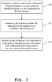
- a flow chart of an exemplary embodiment of the inventive method according to the first aspect of the invention is illustrated.
- a reference antenna is measured for orthogonal field components in a direct spherical near-field system at a well geometrically defined distance.
- the reference antenna is measured for orthogonal field components in an indirect far-field system.
- the orthogonal field components in the indirect far-field system are optimized with respect to the orthogonal field components in the direct spherical near-field system.
- inventive method may further comprise the step of applying a Fourier transformation in order to transform the orthogonal field components in the direct spherical near-field system at other distances.
- the method further comprises the step of identifying an equivalent distance such that the orthogonal field components measured in the indirect far-field system are closest to the transformed orthogonal field components in the direct spherical near-field system.
- the method according to the first aspect of the invention may further comprise the step of transforming the orthogonal field components in terms of magnitude and phase by utilizing the equivalent distance of the indirect far-field system.
- inventive method may further comprise the step of calculating near-field currents in the reactive near-field of the reference antenna by forward and/or back propagating the transformed amplitude and phase of the indirect far-field system.
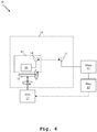
- a first exemplary embodiment of the system 10 is illustrated.
- the system 10 is focused to perform near-field measurements in order to characterize a reference antenna 14 for the two orthogonal field components E ⁇ , E ⁇ .
- a measuring unit 12 performs measurement on the reference antenna 14 through a measuring antenna 11 at a well-defined distance, for instance R 0 as shown in Fig. 1 .
- the measuring unit 12 is further connected to a processing unit 13.
- the connection between the measuring unit 12 and the processing unit 13 is not necessarily required to be a wired connection, a wireless connection in the form of Wireless Local Area Network (WLAN), Web-based interface and so on are also viable.
- the processing unit 13 is adapted to apply a Fourier transformation in order to transform the orthogonal field components E ⁇ , E ⁇ in the near-field system at other distances, for instance at a distance R , where R ⁇ R 0
- the processing unit 13 advantageously stores the measured as well as extrapolated field components for all distances R , R 0 .
- the reference antenna 14 is conventionally driven by antenna driving circuitry 18, which is closely located to the reference antenna 14 in order to reduce insertion loss and signal degradation.
- the reference antenna 14 and the antenna drive circuitry 18 may collectively be referred to as a device under test (DUT) 15 such as mobile phones, radio set, short-range devices and the like.
- the DUT 15 is situated on a turntable 16, which is rotatable along at least two axis by means of a positioning unit 17.
- the positioning unit 17 can be externally controlled, for instance through control commands inputted and/or generated from the processing unit 13.
- the system 10 further comprises an anechoic chamber 19 encompassing the measuring antenna 11, the reference antenna 14, the DUT 15 and the turntable 17.
- a second exemplary embodiment of the system 20 according to the second aspect of the invention is illustrated.
- the system 20 differs from the system 10 of Fig. 4 in that it comprises a shaped reflector 21 in order to perform far-field measurements on the reference antenna 14 for the two orthogonal field components E ⁇ , E ⁇ and the field pattern.
- the shaped reflector 21 is preferably a parabolic reflector, which is situated within the anechoic chamber 19 and enables indirect far-field approach to effectively measure the far-field pattern of the DUT 15.
- the positioning unit 17 is further adapted to control the spatial position of the shaped reflector 21.
- the processing unit 13 also stores the far-field measurement data.
- FIG. 6 an exemplary block diagram of near-field simulation from far-field measurements according to the second aspect of the invention is illustrated. Since the processing unit 13 has already obtained the near-field and far-field measurement data, an optimization of the far-field measurement data 22 is performed with respect to the near-field measurement data 23 according to a certain distance, for instance using L 2 norm.
- the distance r can be varied until the result match the near-field measurements for a specific distance, anywhere between R to R 0 . Consequently, the equivalent distance of the indirect far-field, for instance R eq as shown in Fig. 1 , can be identified.
- a simplified near-field transformation algorithm is sufficient to calculate the near-field currents in the reactive near-field of the DUT 15 and further able to calculate the SAR value to evaluate near-field human exposure at mmWave.
- a conventional near-field probe disrupts the field around the DUT 15 and disadvantageously produces inevitable measurement errors.
- the embodiments of the present invention can be implemented by hardware, software, or any combination thereof.
- Various embodiments of the present invention may be implemented by one or more application specific integrated circuits (ASICs), digital signal processors (DSPs), digital signal processing devices (DSPDs), programmable logic devices (PLDs), field programmable gate arrays (FPGAs), processors, controllers, microcontrollers, microprocessors, or the like.
- ASICs application specific integrated circuits
- DSPs digital signal processors
- DSPDs digital signal processing devices
- PLDs programmable logic devices
- FPGAs field programmable gate arrays
- processors controllers, microcontrollers, microprocessors, or the like.
Landscapes
- Physics & Mathematics (AREA)
- Electromagnetism (AREA)
- Engineering & Computer Science (AREA)
- Computer Networks & Wireless Communication (AREA)
- Signal Processing (AREA)
- General Physics & Mathematics (AREA)
- Variable-Direction Aerials And Aerial Arrays (AREA)
- Quality & Reliability (AREA)
Abstract
Description
- The invention relates to a method and a corresponding system for near-field reconstruction in indirect far-field systems, especially for compact antenna test ranges (CATR) that are used to enable stable far-field conditions in a compact test environment.
- The over the air (OTA) measurements attempt to determine the performance of radio transmitters and receivers (e.g. mobile phones) in a test environment that closely simulate the conditions in which the devices will be tested. For instance, a fifth generation millimeter-wave (5G mmWave) device operating above 24 GHz incorporates millimeter sized antenna arrays or dipole antennas, which become an integral part of the device module packaging. Thus, the only way to characterize and test the performance of the antennas as part of the final product is via OTA measurement.
- For example,
US 8,750,354 A1 describes a method of scanning a digital beam formed phased array in a nearfield by creating an open architecture approach to replacing the analog reference points with digital reference points and the ability to perform measurements. - Accordingly, the object of the invention is to provide a method and a system for near-field reconstruction in indirect far-field systems, especially by combining both indirect far-field and near-field approaches in order to gain the aforementioned advantages from both approaches.
- The object is solved by the features of the first independent claim for the method and by the features of the second independent claim for the system. The dependent claims contain further developments.
- According to a first aspect of the invention, a method for near-field reconstruction in indirect far-field systems is provided. The method comprises the steps of measuring a reference antenna for orthogonal field components in a direct spherical near-field system at a well geometrically defined distance, measuring the reference antenna for orthogonal field components in an indirect far-field system and optimizing the orthogonal field components in the indirect far-field system with respect to the orthogonal field components in the direct spherical near-field system. Therefore, the near-field approach and the indirect far-field approach are advantageously combined in order to reconstruct near-field in an indirect far-field system.
- According to a first preferred implementation form of said first aspect of the invention, the method further comprises the step of applying a Fourier transformation in order to transform the orthogonal field components in the direct spherical near-field system at other distances. Advantageously, near-field to far-field and/or near-field to near-field algorithms can be used to extrapolate the near-field measurements and thereby increasing the side lobe level accuracy significantly.
- According to a second preferred implementation form of said first aspect of the invention, the method further comprises the step of identifying an equivalent distance such that the orthogonal field components measured in the indirect far-field system are closest to the transformed orthogonal field components in the direct spherical near-field system. Advantageously, the equivalent distance, at which the field is measured in the indirect far-field system, is identified in a simplified manner in order to perform near-field transformations.
- According to a further preferred implementation form of said first aspect of the invention, the method further comprises the step of transforming the orthogonal field components in terms of magnitude and phase by utilizing the equivalent distance of the indirect far-field system. Advantageously, the additional phase information along with magnitude enables the most accurate evaluation of the field patterns especially in nulls and side lobes.
- According to a further preferred implementation form of said first aspect of the invention, the method further comprises the step of calculating near-field currents in the reactive near-field of the reference antenna by forward and/or back propagating the transformed amplitude and phase of the indirect far-field system. Advantageously, the near-field currents obtained in the reactive near-field of the reference antenna allows to identify critical antenna design parameters, for instance antenna design defects, specific absorption rate (SAR) and so on.
- According to a second aspect of the invention, a system for near-field reconstruction in indirect far-field systems is provided. The system comprises a measuring antenna, a measuring unit and a processing unit. In this context, the measuring unit is adapted to measure a reference antenna for orthogonal field components in a direct spherical near-field system at a well geometrically defined distance. The measuring unit is further adapted to measure the reference antenna for orthogonal field components in an indirect far-field system. In addition, the processing unit is adapted to optimize the orthogonal field components in the indirect far-field system with respect to the orthogonal field components in the direct spherical near-field system.
- Hence, the reference antenna is characterized for each relevant field components, for example Eθ , Eϕ in the direct spherical near-field system at a defined distance. The indirect far-field system is supposed, for instance as a CATR where the reference antenna is further characterized for the field components patterns. Therefore, the near-field approach and the indirect far-field approach are advantageously combined in order to reconstruct near-field in an indirect far-field system.
- According to a first preferred implementation form of said second aspect of the invention, the processing unit is further adapted to apply a Fourier transformation in order to transform the orthogonal field components in the direct spherical near-field system at other distances. Hence, near-field to far-field (NF/FF) and/or near-field to near-field (NF/NF) algorithms can be used to transform the measured field components, for example Eθ , Eϕ at other distances that are preferably not equal to the defined distance where the reference antenna is previously characterized in the direct spherical near-field system. Advantageously, NF/FF and/or NF/NF algorithms can be used to extrapolate the near-field measurements and thereby increasing the side lobe level accuracy significantly.
- According to a second preferred implementation form of said second aspect of the invention, the processing unit is further adapted to identify an equivalent distance such that the orthogonal field components measured in the indirect far-field system are closest to the transformed orthogonal field components in the direct spherical near-field system. Advantageously, the equivalent distance at which the field is measured in the indirect far-field system is identified in a simplified manner in order to perform near-field transformations.
- According to a further preferred implementation form of said second aspect of the invention, the equivalent distance corresponds to the equivalent range length of the indirect far-field system. Advantageously, additional power measurements, for instance total radiated power, time-averaged power density and so on can be performed with ease by knowing the equivalent range length of the indirect far-field system.
- According to a further preferred implementation form of said second aspect of the invention, the processing unit is further adapted to transform the orthogonal field components in terms of magnitude and phase by utilizing the equivalent distance of the indirect far-field system. Advantageously, the additional phase information along with magnitude enables the most accurate evaluation of the field patterns especially in nulls and side lobes.
- According to a further preferred implementation form of said second aspect of the invention, the processing unit is further adapted to calculate near-field currents in the reactive near-field of the reference antenna by forward and/or back propagating the transformed amplitude and phase of the indirect far-field system. Advantageously, the near-field currents obtained in the reactive near-field of the reference antenna allows to identify critical antenna design parameters, for instance antenna design defects, specific absorption rate (SAR) and so on.
- According to a further preferred implementation form of said second aspect of the invention, the system further comprises a turntable adapted rotate the reference antenna relative to the measuring antenna along at least two axis. Advantageously, the field components, for example Eθ , Eϕ are measured with greater accuracy.
- According to a further preferred implementation form of said second aspect of the invention, the system further comprises a reflector, preferably a shaped reflector. The reflector provides the means to convert a spherical phase front to and/or from the measuring antenna into a planar phase front close to the aperture. Such an approach advantageously allows a compact range that creates a plane wave field at distances considerably shorter than those needed under conventional far-field criteria.
- According to a further preferred implementation form of said second aspect of the invention, the system further comprises a positioning unit adapted to control the turntable rotation and the spatial position of the reflector. Advantageously, the measurement accuracy is further improved.
- According to a further preferred implementation form of said second aspect of the invention, the system further comprises an anechoic chamber encompassing the reference antenna, the measuring antenna, the turntable and the reflector. Advantageously, the standing wave reduction capability of the anechoic chamber greatly improves the OTA measurement reliability.
- Exemplary embodiments of the invention are now further explained with respect to the drawings by way of example only, and not for limitation. In the drawings:
- Fig. 1
- shows antenna radiation regions in free space by way of an example,
- Fig. 2a
- shows a block diagram of far-field simulation from near-field measurements by way of an example,
- Fig. 2b
- shows a block diagram of far-field measurement in a CATR environment by way of an example,
- Fig. 3
- shows a flow chart of an exemplary embodiment of the inventive method according to the first aspect of the invention,
- Fig. 4
- shows a first exemplary embodiment of the system according to the second aspect of the invention,
- Fig. 5
- shows a second exemplary embodiment of the system according to the second aspect of the invention, and
- Fig. 6
- shows an exemplary block diagram of near-field simulation from far-field measurements according to the second aspect of the invention.
- Reference will now be made in detail to the embodiments of the present invention, examples of which are illustrated in the accompanying drawings. However, the following embodiments of the present invention may be variously modified and the range of the present invention is not limited by the following embodiments.
- As shown in
Fig. 1 , an antenna transmitting radio frequency (RF) signals is basically radiating electromagnetic (EM) waves into free space, where the EM field characteristics vary as a function of distance from the radiating antenna. The antenna radiation region is broadly categorized in two regions, the near-field region and the far-field region. - The near-field region is the region right next to the antenna, which is defined by the distance relationship:

- RNF is the near-field measurement distance from the antenna,
- D is the maximum linear dimension of the antenna, and
- λ is the wavelength of EM waves.
- However, in this region, the fields are sort of unpredictable and obscure due to the overlapping and commingling of the reactive field of the antenna.
- The far-field region starts from the far-field boundary, which is defined by the distance relationship:

- In this region, the EM fields are dominated by radiating fields that are orthogonal to each other and to the direction of propagation as with plane waves. Generally, the OTA measurements are based on far-field region measurements since antennas are usually used to transfer signals at large distances which are considered to be in the far-field region. However, the measurements in the far-field region are required to consider that the distance from the antenna must be much greater than the size of the antenna and the wavelength. Therefore, a direct far-field measurement setup requires a large test environment and severely limits the side lobe level (SLL) accuracy due to the physics of propagation.
- Near-field measurements enable antenna probing within the radiative near-field region. For example,
U.S. Patent No. 8,750,354 B1 shows an open architecture design for a digital near-field test system for near-field testing of a phased array antenna that allows the ability to use the components of an individual phased array antenna to be tested in conjunction with a near-field scanner probe. - One approach to simulate far-field conditions is to measure the antenna in the near-field region and transform the near-field E-field measurements into far-field components. As shown in
Fig. 2a , the near-field to far-field transform (NF/FF) test method computes the performance metrics defined for far field by using mathematical near-field to far-field transformations 2. Thus, the antenna radiated near-field beam patterns 1 are measured first. Next these measurements are translated into far-field metrics 3 using the near-field to far-fieldmathematical transform 2. - Although the aforementioned NF/FF transform test method achieves higher SLL accuracy, the near-field test setup is more complex than the direct far-field measurement and is quite limited in application to OTA measurements as the method requires phase information in addition to the magnitude, thereby arises complexities for measuring modulated signals.
- Another approach to generate stable far-field conditions is the indirect far-field method that creates the far-field environment using a transformation within the test chamber by means of, for instance, parabolic reflector, Fresnel lens and so on. As shown in
Fig. 2b , a CATR test environment is utilizing a parabolic reflector 8 in order to linearize the radiatedsignals 7, which are transmitted 9 to the device under test (DUT) 4. In the case theDUT 4 radiates awave front 9 to the reflector 8, the reflector 8 then collimates the radiated spherical wave front into a feed antenna 6. The separation between theDUT 4 and the feed antenna 6 is adequate so that the emanating spherical wave reaches nearly plane phase fronts from theDUT 4 to the feed antenna 6. Usually, theDUT 4 is mounted on a low scattering mount 5. - Although, the indirect far-field approach is more complex than the direct far-field approach, the former can perform in a more compact environment and can advantageously deliver good far-field condition with higher SLL accuracy. However, in contrast to the direct far-field approach, it is not possible to simulate near-field conditions from indirect far-field measurements since the far-field distance is seen as the focal length; that is the distance between the feed antenna 6 and the reflector 8. In other words, the near-field simulation requires proper knowledge of the equivalent distance at which the field is measured, which is not available from the indirect far-field measurements.
- Hence, the indirect far-field measurement like CATR and near-field measurement approaches are therefore opposed to each other. The indirect far-field approaches indeed allow to create a nice far-field condition in a compact environment and further allow to measure typical quantities looked at in OTA measurements with good accuracy by field magnitude measurements only. On the contrary, near-field measurement approach cannot cover all types of OTA measurements as they require to measure the phase of the electric and/or magnetic field components.
- However, if the phase can be measured, the near-field measurement approach can be very beneficial, for instance using near to far-field transformation algorithms the measurements taken in the very proximity of a DUT can be accurately extrapolated to infinity and can yield the most accurate evaluation of far-field patterns especially in null and side lobes. In addition, near to near-field transformation algorithms can also be used and fields measured over a surface surrounding the DUT can be back-propagated towards the DUT so that, for instance, near-field currents can be observed to identify antenna design defects. The back-propagation also facilitates power density assessments in order to evaluate near-field human exposure at mmWave.
- In
Fig. 3 , a flow chart of an exemplary embodiment of the inventive method according to the first aspect of the invention is illustrated. In afirst step 100, a reference antenna is measured for orthogonal field components in a direct spherical near-field system at a well geometrically defined distance. In asecond step 101, the reference antenna is measured for orthogonal field components in an indirect far-field system. In athird step 102, the orthogonal field components in the indirect far-field system are optimized with respect to the orthogonal field components in the direct spherical near-field system. - In addition to this, the inventive method may further comprise the step of applying a Fourier transformation in order to transform the orthogonal field components in the direct spherical near-field system at other distances.
- It might be further advantageous if the method further comprises the step of identifying an equivalent distance such that the orthogonal field components measured in the indirect far-field system are closest to the transformed orthogonal field components in the direct spherical near-field system.
- Moreover, the method according to the first aspect of the invention may further comprise the step of transforming the orthogonal field components in terms of magnitude and phase by utilizing the equivalent distance of the indirect far-field system.
- In addition to this, the inventive method may further comprise the step of calculating near-field currents in the reactive near-field of the reference antenna by forward and/or back propagating the transformed amplitude and phase of the indirect far-field system.
- In
Fig. 4 , a first exemplary embodiment of the system 10 according to the second aspect of the invention is illustrated. The system 10 is focused to perform near-field measurements in order to characterize areference antenna 14 for the two orthogonal field components Eθ , Eϕ . A measuringunit 12 performs measurement on thereference antenna 14 through a measuringantenna 11 at a well-defined distance, for instance R 0 as shown inFig. 1 . For post-processing the measurement data, the measuringunit 12 is further connected to aprocessing unit 13. The connection between the measuringunit 12 and theprocessing unit 13 is not necessarily required to be a wired connection, a wireless connection in the form of Wireless Local Area Network (WLAN), Web-based interface and so on are also viable. In this context, theprocessing unit 13 is adapted to apply a Fourier transformation in order to transform the orthogonal field components Eθ , Eϕ in the near-field system at other distances, for instance at a distance R, where
- The
processing unit 13 advantageously stores the measured as well as extrapolated field components for all distances R,R 0. - The
reference antenna 14 is conventionally driven byantenna driving circuitry 18, which is closely located to thereference antenna 14 in order to reduce insertion loss and signal degradation. Thereference antenna 14 and theantenna drive circuitry 18 may collectively be referred to as a device under test (DUT) 15 such as mobile phones, radio set, short-range devices and the like. TheDUT 15 is situated on aturntable 16, which is rotatable along at least two axis by means of a positioning unit 17. The positioning unit 17 can be externally controlled, for instance through control commands inputted and/or generated from theprocessing unit 13. - The system 10 further comprises an
anechoic chamber 19 encompassing the measuringantenna 11, thereference antenna 14, theDUT 15 and the turntable 17. - In
Fig. 5 , a second exemplary embodiment of thesystem 20 according to the second aspect of the invention is illustrated. Thesystem 20 differs from the system 10 ofFig. 4 in that it comprises a shapedreflector 21 in order to perform far-field measurements on thereference antenna 14 for the two orthogonal field components Eθ , Eϕ and the field pattern. The shapedreflector 21 is preferably a parabolic reflector, which is situated within theanechoic chamber 19 and enables indirect far-field approach to effectively measure the far-field pattern of theDUT 15. In this context, the positioning unit 17 is further adapted to control the spatial position of the shapedreflector 21. Here theprocessing unit 13 also stores the far-field measurement data. - In
Fig. 6 , an exemplary block diagram of near-field simulation from far-field measurements according to the second aspect of the invention is illustrated. Since theprocessing unit 13 has already obtained the near-field and far-field measurement data, an optimization of the far-field measurement data 22 is performed with respect to the near-field measurement data 23 according to a certain distance, for instance using L 2 norm. An optimization algorithm can be defined based on the following Inverse Fourier Transform:
- A is the magnitude, and
- e-jk.r is the phase, as a function of distance r.
- Thus, the distance r can be varied until the result match the near-field measurements for a specific distance, anywhere between R to R 0. Consequently, the equivalent distance of the indirect far-field, for instance Req as shown in
Fig. 1 , can be identified. - Once the
processing unit 13 identifies the equivalent distance of the indirect far-field Req , the field components can be transformed in terms of magnitude and phase and can be forward or back propagated to any other surface using near-field transformation algorithms as following:
- It is particularly advantageous that a simplified near-field transformation algorithm is sufficient to calculate the near-field currents in the reactive near-field of the
DUT 15 and further able to calculate the SAR value to evaluate near-field human exposure at mmWave. On the contrary, a conventional near-field probe disrupts the field around theDUT 15 and disadvantageously produces inevitable measurement errors. - The embodiments of the present invention can be implemented by hardware, software, or any combination thereof. Various embodiments of the present invention may be implemented by one or more application specific integrated circuits (ASICs), digital signal processors (DSPs), digital signal processing devices (DSPDs), programmable logic devices (PLDs), field programmable gate arrays (FPGAs), processors, controllers, microcontrollers, microprocessors, or the like.
- While various embodiments of the present invention have been described above, it should be understood that they have been presented by way of example only, and not limitation. Numerous changes to the disclosed embodiments can be made in accordance with the disclosure herein without departing from the spirit or scope of the invention. Thus, the breadth and scope of the present invention should not be limited by any of the above described embodiments. Rather, the scope of the invention should be defined in accordance with the following claims and their equivalents.
- Although the invention has been illustrated and described with respect to one or more implementations, equivalent alterations and modifications will occur to others skilled in the art upon the reading and understanding of this specification and the annexed drawings. In addition, while a particular feature of the invention may have been disclosed with respect to only one of several implementations, such feature may be combined with one or more other features of the other implementations as may be desired and advantageous for any given or particular application.
Claims (15)
- A method for near-field reconstruction in indirect far-field systems comprising the steps of:measuring a reference antenna (14) for orthogonal field components in a direct spherical near-field system at a well geometrically defined distance (R0),measuring the reference antenna (14) for orthogonal field components in an indirect far-field system, andoptimizing the orthogonal field components in the indirect far-field system with respect to the orthogonal field components in the direct spherical near-field system.
- The method according to claim 1,
wherein the method further comprises the step of applying a Fourier transformation in order to transform the orthogonal field components in the direct spherical near-field system at other distances. - The method according to claim 1 or 2,
wherein the method further comprises the step of identifying an equivalent distance (Req) such that the orthogonal field components measured in the indirect far-field system are closest to the transformed orthogonal field components in the direct spherical near-field system. - The method according to claim 3,
wherein the method further comprises the step of transforming the orthogonal field components in terms of magnitude and phase by utilizing the equivalent distance (Req) of the indirect far-field system. - The method according to claim 4,
wherein the method further comprises the step of calculating near-field currents in the reactive near-field of the reference antenna (14) by forward and/or back propagating the transformed amplitude and phase of the indirect far-field system. - A system (10, 20) for near-field reconstruction in indirect far-field systems comprising:a measuring antenna (11),a measuring unit (12), anda processing unit (13),wherein the measuring unit (12) is adapted to measure a reference antenna (14) for orthogonal field components in a direct spherical near-field system at a well geometrically defined distance (R0),
wherein the measuring unit (12) is further adapted to measure the reference antenna (14) for orthogonal field components in an indirect far-field system, and
wherein the processing unit (13) is adapted to optimize the orthogonal field components in the indirect far-field system with respect to the orthogonal field components in the direct spherical near-field system. - The system according to claim 6,
wherein the processing unit (13) is further adapted to apply a Fourier transformation in order to transform the orthogonal field components in the direct spherical near-field system at other distances. - The system according to claim 6 or 7,
wherein the processing unit (13) is further adapted to identify an equivalent distance (Req) such that the orthogonal field components measured in the indirect far-field system are closest to the transformed orthogonal field components in the direct spherical near-field system. - The system according to claim 8,
wherein the equivalent distance (Req) corresponds to the equivalent range length of the indirect far-field system. - The system according to claim 8,
wherein the processing unit (13) is further adapted to transform the orthogonal field components in terms of magnitude and phase by utilizing the equivalent distance (Req) of the indirect far-field system. - The system according to claim 10,
wherein the processing unit (13) is further adapted to calculate near-field currents in the reactive near-field of the reference antenna (14) by forward and/or back propagating the transformed amplitude and phase of the indirect far-field system. - The system according to any of claims 6 to 11,
wherein the system (10, 20) further comprises a turntable (16) adapted rotate the reference antenna (14) relative to the measuring antenna (11) along at least two axis. - The system according to any of claims 6 to 12,
wherein the system (10, 20) further comprises a reflector (21), preferably a shaped reflector. - The system according to any of claims 6 to 13,
wherein the system (10, 20) further comprises a positioning unit (17) adapted to control the turntable (16) rotation and the spatial position of the reflector (21). - The system according to any of claims 6 to 14,
wherein the system (10, 20) further comprises an anechoic chamber (19) encompassing the reference antenna (14), the measuring antenna (11), the turntable (16) and the reflector (21).
Priority Applications (3)
| Application Number | Priority Date | Filing Date | Title |
|---|---|---|---|
| EP19185635.0A EP3764110B8 (en) | 2019-07-11 | 2019-07-11 | Method and system for near-field reconstruction in indirect far-field systems |
| US16/600,119 US10848252B1 (en) | 2019-07-11 | 2019-10-11 | Method and system for near-field reconstruction in indirect far-field systems |
| CN201911094299.0A CN112213566B (en) | 2019-07-11 | 2019-11-11 | Methods and systems for near-field reconstruction in indirect far-field systems |
Applications Claiming Priority (1)
| Application Number | Priority Date | Filing Date | Title |
|---|---|---|---|
| EP19185635.0A EP3764110B8 (en) | 2019-07-11 | 2019-07-11 | Method and system for near-field reconstruction in indirect far-field systems |
Publications (3)
| Publication Number | Publication Date |
|---|---|
| EP3764110A1 true EP3764110A1 (en) | 2021-01-13 |
| EP3764110B1 EP3764110B1 (en) | 2022-03-16 |
| EP3764110B8 EP3764110B8 (en) | 2022-04-20 |
Family
ID=67253707
Family Applications (1)
| Application Number | Title | Priority Date | Filing Date |
|---|---|---|---|
| EP19185635.0A Active EP3764110B8 (en) | 2019-07-11 | 2019-07-11 | Method and system for near-field reconstruction in indirect far-field systems |
Country Status (3)
| Country | Link |
|---|---|
| US (1) | US10848252B1 (en) |
| EP (1) | EP3764110B8 (en) |
| CN (1) | CN112213566B (en) |
Families Citing this family (6)
| Publication number | Priority date | Publication date | Assignee | Title |
|---|---|---|---|---|
| US11081788B1 (en) * | 2020-04-03 | 2021-08-03 | The Boeing Company | System and method for near-field testing of a phased array antenna |
| KR102733103B1 (en) * | 2021-02-02 | 2024-11-25 | 인천대학교 산학협력단 | Apparatus for Estimating Electromagnetic Waves Electric Field of Near Field Using Electric Field of Far Field |
| US11474138B1 (en) * | 2021-10-19 | 2022-10-18 | Rohde & Schwarz Gmbh & Co. Kg | Over-the-air measurement system |
| CN116540200B (en) * | 2023-05-09 | 2023-11-10 | 南京航空航天大学 | Optimized measurement method for near-field prediction far-field RCS |
| CN116735984B (en) * | 2023-06-15 | 2026-06-23 | 东南大学 | Method for rapidly calculating non-uniform intra-phantom SAR based on artificial neural network |
| CN120928051A (en) * | 2025-07-02 | 2025-11-11 | 东南大学 | Antenna pattern reconstruction method |
Citations (7)
| Publication number | Priority date | Publication date | Assignee | Title |
|---|---|---|---|---|
| US4201987A (en) * | 1978-03-03 | 1980-05-06 | The United States Of America As Represented By The Secretary Of The Navy | Method for determining antenna near-fields from measurements on a spherical surface |
| US20100039332A1 (en) * | 2007-11-05 | 2010-02-18 | Dybdal Robert B | Quasi-Compact Range |
| US8750354B1 (en) | 2011-05-10 | 2014-06-10 | Lockheed Martin Corporation | Nearfield testing architecture |
| US20170242061A1 (en) * | 2014-10-16 | 2017-08-24 | Kathrein-Werke Kg | Test apparatus and a method of testing of an antenna |
| US20180006745A1 (en) * | 2016-06-30 | 2018-01-04 | Keysight Technologies, Inc. | Compact system for characterizing a device under test (dut) having integrated antenna array |
| US20190086459A1 (en) * | 2017-07-07 | 2019-03-21 | The Governors Of The University Of Alberta | Systems and methods for measuring and characterizing antenna performance |
| EP3462190A1 (en) * | 2017-09-29 | 2019-04-03 | Rohde & Schwarz GmbH & Co. KG | Measurement system and method for performing test measurements |
Family Cites Families (11)
| Publication number | Priority date | Publication date | Assignee | Title |
|---|---|---|---|---|
| JPH1062467A (en) * | 1996-06-12 | 1998-03-06 | Mitsubishi Electric Corp | Unnecessary electromagnetic wave measuring system |
| US7154435B2 (en) * | 2005-04-04 | 2006-12-26 | The Boeing Company | Sparse numerical array feed for compact antenna and RCS ranges |
| JP2007027902A (en) * | 2005-07-12 | 2007-02-01 | Ntt Docomo Inc | Antenna device, electric field strength measurement system |
| JP4944834B2 (en) * | 2008-05-01 | 2012-06-06 | 株式会社エヌ・ティ・ティ・ドコモ | Far-field measurement system, far-field measurement method |
| US20100149038A1 (en) * | 2008-12-17 | 2010-06-17 | Brown Kenneth W | Portable Millimeter-Wave Near Field Scanner |
| US20120162031A1 (en) * | 2010-12-22 | 2012-06-28 | Electronics And Telecommunications Research Institute | Method for predicting phase pattern using magnitude pattern in near-field or fresnel field |
| US9116232B2 (en) * | 2012-04-13 | 2015-08-25 | Apple Inc. | Methods and apparatus for testing satellite navigation system receiver performance |
| GB201517005D0 (en) * | 2015-09-25 | 2015-11-11 | Johnson Electric Sa | Multi-frequency antenna module |
| US10044104B1 (en) * | 2017-07-14 | 2018-08-07 | Rohde & Schwarz Gmbh & Co. Kg | Test arrangement and test method |
| US9991591B1 (en) * | 2017-07-20 | 2018-06-05 | Rohde & Schwarz Gmbh & Co. Kg | Test arrangement and test method for a beamsteered wireless device under test |
| CN107271977B (en) | 2017-07-25 | 2020-04-24 | 哈尔滨工业大学 | High-precision SAR echo simulation method based on mobile excitation source FDTD algorithm |
-
2019
- 2019-07-11 EP EP19185635.0A patent/EP3764110B8/en active Active
- 2019-10-11 US US16/600,119 patent/US10848252B1/en active Active
- 2019-11-11 CN CN201911094299.0A patent/CN112213566B/en active Active
Patent Citations (7)
| Publication number | Priority date | Publication date | Assignee | Title |
|---|---|---|---|---|
| US4201987A (en) * | 1978-03-03 | 1980-05-06 | The United States Of America As Represented By The Secretary Of The Navy | Method for determining antenna near-fields from measurements on a spherical surface |
| US20100039332A1 (en) * | 2007-11-05 | 2010-02-18 | Dybdal Robert B | Quasi-Compact Range |
| US8750354B1 (en) | 2011-05-10 | 2014-06-10 | Lockheed Martin Corporation | Nearfield testing architecture |
| US20170242061A1 (en) * | 2014-10-16 | 2017-08-24 | Kathrein-Werke Kg | Test apparatus and a method of testing of an antenna |
| US20180006745A1 (en) * | 2016-06-30 | 2018-01-04 | Keysight Technologies, Inc. | Compact system for characterizing a device under test (dut) having integrated antenna array |
| US20190086459A1 (en) * | 2017-07-07 | 2019-03-21 | The Governors Of The University Of Alberta | Systems and methods for measuring and characterizing antenna performance |
| EP3462190A1 (en) * | 2017-09-29 | 2019-04-03 | Rohde & Schwarz GmbH & Co. KG | Measurement system and method for performing test measurements |
Non-Patent Citations (4)
| Title |
|---|
| GUO BINXING ET AL: "An improved near-field measurement method and near-far field transformation for cylindrical conformal phased array antenna", 2015 12TH IEEE INTERNATIONAL CONFERENCE ON ELECTRONIC MEASUREMENT & INSTRUMENTS (ICEMI), IEEE, vol. 2, 16 July 2015 (2015-07-16), pages 789 - 792, XP032913263, DOI: 10.1109/ICEMI.2015.7494331 * |
| PIVNENKO S ET AL: "Application of single probe correction file for multi-frequency spherical near-field antenna measurements", 2016 10TH EUROPEAN CONFERENCE ON ANTENNAS AND PROPAGATION (EUCAP), EUROPEAN ASSOCIATION OF ANTENNAS AND PROPAGATION, 10 April 2016 (2016-04-10), pages 1 - 5, XP032906279, DOI: 10.1109/EUCAP.2016.7481276 * |
| SHISHKOVA A V ET AL: "Phase radiation characteristics of an open-ended circular waveguide", 20070605, vol. 1, no. 3, 5 June 2007 (2007-06-05), pages 790 - 797, XP006028820 * |
| TOSHEV ALEXANDER G: "Application of Fourier Integrals for Determination of Antenna Far-Field Patterns from Measurements at Fresnel Distances", IEEE TRANSACTIONS ON ANTENNAS AND PROPAGATION, IEEE SERVICE CENTER, PISCATAWAY, NJ, US, vol. 65, no. 4, 1 April 2017 (2017-04-01), pages 1700 - 1705, XP011644912, ISSN: 0018-926X, [retrieved on 20170405], DOI: 10.1109/TAP.2017.2671034 * |
Also Published As
| Publication number | Publication date |
|---|---|
| EP3764110B8 (en) | 2022-04-20 |
| CN112213566B (en) | 2026-01-02 |
| US10848252B1 (en) | 2020-11-24 |
| CN112213566A (en) | 2021-01-12 |
| EP3764110B1 (en) | 2022-03-16 |
Similar Documents
| Publication | Publication Date | Title |
|---|---|---|
| US10848252B1 (en) | Method and system for near-field reconstruction in indirect far-field systems | |
| US12191920B2 (en) | Method, apparatus and system for measuring total radiated power of array antenna | |
| JP7329085B2 (en) | High-speed OTA production line test platform | |
| US11750303B2 (en) | Compact system for characterizing a device under test (DUT) having integrated antenna array | |
| US20180006745A1 (en) | Compact system for characterizing a device under test (dut) having integrated antenna array | |
| US10768216B2 (en) | Test arrangement and test method | |
| KR101360280B1 (en) | Multichannel absorberless near field measurement system | |
| CN108594026A (en) | A kind of near-field test method for rebuilding antenna array far-field pattern in radiading near-field region | |
| TWI540792B (en) | A far-field calibration system of an antenna arrary system | |
| Lundgren et al. | A near-field measurement and calibration technique: Radio-frequency electromagnetic field exposure assessment of millimeter-wave 5G devices | |
| CN116076039A (en) | Method and system for over-the-air testing of millimeter wave antenna arrays | |
| Scattone et al. | Preliminary assesment of millimeter wave plane wave generator for 5G device testing | |
| Hamberger et al. | Correction of over-the-air transmit and receive wireless device performance errors due to displaced antenna positions in the measurement coordinate system | |
| US20190379125A1 (en) | Freespace antenna measurement system | |
| CN115134008B (en) | Comprehensive integrated test system and method for OTA test | |
| Xiao et al. | An accurate analytical method to determine the range of quiet zone in compact antenna test range | |
| Du et al. | Antenna pattern retrieval from reflection coefficient measurements with reflective loads | |
| US11486922B1 (en) | Over-the-air measurement system and over-the-air measurement method | |
| Yu et al. | The antenna pattern reconstruction based on mid-field phaseless measured data using a simplified extrapolation technique | |
| Scattone et al. | Production measurement of 5G millimeter wave plane wave generators | |
| An et al. | An efficient multi‐probe enabled midfield over‐the‐air test method for 5G base station antenna pattern reconstruction | |
| Liu et al. | Challenges and applicability of OTA measurement for 5G millimeter wave mobile device | |
| Tang et al. | Enhanced peak beam deviation estimation based on extrapolation method for a transmitarray compact antenna test range | |
| Gao et al. | An efficient multi-beam pattern measurement campaign for millimeter-wave phased arrays | |
| Yang et al. | A Novel Linear Antenna Array Calibration Method Based on Scattering Signals |
Legal Events
| Date | Code | Title | Description |
|---|---|---|---|
| PUAI | Public reference made under article 153(3) epc to a published international application that has entered the european phase |
Free format text: ORIGINAL CODE: 0009012 |
|
| STAA | Information on the status of an ep patent application or granted ep patent |
Free format text: STATUS: THE APPLICATION HAS BEEN PUBLISHED |
|
| AK | Designated contracting states |
Kind code of ref document: A1 Designated state(s): AL AT BE BG CH CY CZ DE DK EE ES FI FR GB GR HR HU IE IS IT LI LT LU LV MC MK MT NL NO PL PT RO RS SE SI SK SM TR |
|
| AX | Request for extension of the european patent |
Extension state: BA ME |
|
| STAA | Information on the status of an ep patent application or granted ep patent |
Free format text: STATUS: REQUEST FOR EXAMINATION WAS MADE |
|
| 17P | Request for examination filed |
Effective date: 20210512 |
|
| RBV | Designated contracting states (corrected) |
Designated state(s): AL AT BE BG CH CY CZ DE DK EE ES FI FR GB GR HR HU IE IS IT LI LT LU LV MC MK MT NL NO PL PT RO RS SE SI SK SM TR |
|
| GRAP | Despatch of communication of intention to grant a patent |
Free format text: ORIGINAL CODE: EPIDOSNIGR1 |
|
| STAA | Information on the status of an ep patent application or granted ep patent |
Free format text: STATUS: GRANT OF PATENT IS INTENDED |
|
| INTG | Intention to grant announced |
Effective date: 20211123 |
|
| GRAS | Grant fee paid |
Free format text: ORIGINAL CODE: EPIDOSNIGR3 |
|
| GRAA | (expected) grant |
Free format text: ORIGINAL CODE: 0009210 |
|
| STAA | Information on the status of an ep patent application or granted ep patent |
Free format text: STATUS: THE PATENT HAS BEEN GRANTED |
|
| AK | Designated contracting states |
Kind code of ref document: B1 Designated state(s): AL AT BE BG CH CY CZ DE DK EE ES FI FR GB GR HR HU IE IS IT LI LT LU LV MC MK MT NL NO PL PT RO RS SE SI SK SM TR |
|
| REG | Reference to a national code |
Ref country code: GB Ref legal event code: FG4D |
|
| RBV | Designated contracting states (corrected) |
Designated state(s): AL AT BE BG CY CZ DE DK EE ES FI FR GB GR HR HU IS IT LT LU LV MC MK MT NL NO PL PT RO RS SE SI SK SM TR |
|
| REG | Reference to a national code |
Ref country code: DE Ref legal event code: R096 Ref document number: 602019012527 Country of ref document: DE |
|
| REG | Reference to a national code |
Ref country code: IE Ref legal event code: FG4D |
|
| REG | Reference to a national code |
Ref country code: AT Ref legal event code: REF Ref document number: 1476267 Country of ref document: AT Kind code of ref document: T Effective date: 20220415 |
|
| REG | Reference to a national code |
Ref country code: LT Ref legal event code: MG9D |
|
| REG | Reference to a national code |
Ref country code: NL Ref legal event code: MP Effective date: 20220316 |
|
| PG25 | Lapsed in a contracting state [announced via postgrant information from national office to epo] |
Ref country code: SE Free format text: LAPSE BECAUSE OF FAILURE TO SUBMIT A TRANSLATION OF THE DESCRIPTION OR TO PAY THE FEE WITHIN THE PRESCRIBED TIME-LIMIT Effective date: 20220316 Ref country code: RS Free format text: LAPSE BECAUSE OF FAILURE TO SUBMIT A TRANSLATION OF THE DESCRIPTION OR TO PAY THE FEE WITHIN THE PRESCRIBED TIME-LIMIT Effective date: 20220316 Ref country code: NO Free format text: LAPSE BECAUSE OF FAILURE TO SUBMIT A TRANSLATION OF THE DESCRIPTION OR TO PAY THE FEE WITHIN THE PRESCRIBED TIME-LIMIT Effective date: 20220616 Ref country code: LT Free format text: LAPSE BECAUSE OF FAILURE TO SUBMIT A TRANSLATION OF THE DESCRIPTION OR TO PAY THE FEE WITHIN THE PRESCRIBED TIME-LIMIT Effective date: 20220316 Ref country code: HR Free format text: LAPSE BECAUSE OF FAILURE TO SUBMIT A TRANSLATION OF THE DESCRIPTION OR TO PAY THE FEE WITHIN THE PRESCRIBED TIME-LIMIT Effective date: 20220316 Ref country code: BG Free format text: LAPSE BECAUSE OF FAILURE TO SUBMIT A TRANSLATION OF THE DESCRIPTION OR TO PAY THE FEE WITHIN THE PRESCRIBED TIME-LIMIT Effective date: 20220616 |
|
| REG | Reference to a national code |
Ref country code: AT Ref legal event code: MK05 Ref document number: 1476267 Country of ref document: AT Kind code of ref document: T Effective date: 20220316 |
|
| PG25 | Lapsed in a contracting state [announced via postgrant information from national office to epo] |
Ref country code: LV Free format text: LAPSE BECAUSE OF FAILURE TO SUBMIT A TRANSLATION OF THE DESCRIPTION OR TO PAY THE FEE WITHIN THE PRESCRIBED TIME-LIMIT Effective date: 20220316 Ref country code: GR Free format text: LAPSE BECAUSE OF FAILURE TO SUBMIT A TRANSLATION OF THE DESCRIPTION OR TO PAY THE FEE WITHIN THE PRESCRIBED TIME-LIMIT Effective date: 20220617 Ref country code: FI Free format text: LAPSE BECAUSE OF FAILURE TO SUBMIT A TRANSLATION OF THE DESCRIPTION OR TO PAY THE FEE WITHIN THE PRESCRIBED TIME-LIMIT Effective date: 20220316 |
|
| PG25 | Lapsed in a contracting state [announced via postgrant information from national office to epo] |
Ref country code: NL Free format text: LAPSE BECAUSE OF FAILURE TO SUBMIT A TRANSLATION OF THE DESCRIPTION OR TO PAY THE FEE WITHIN THE PRESCRIBED TIME-LIMIT Effective date: 20220316 |
|
| PG25 | Lapsed in a contracting state [announced via postgrant information from national office to epo] |
Ref country code: SM Free format text: LAPSE BECAUSE OF FAILURE TO SUBMIT A TRANSLATION OF THE DESCRIPTION OR TO PAY THE FEE WITHIN THE PRESCRIBED TIME-LIMIT Effective date: 20220316 Ref country code: SK Free format text: LAPSE BECAUSE OF FAILURE TO SUBMIT A TRANSLATION OF THE DESCRIPTION OR TO PAY THE FEE WITHIN THE PRESCRIBED TIME-LIMIT Effective date: 20220316 Ref country code: RO Free format text: LAPSE BECAUSE OF FAILURE TO SUBMIT A TRANSLATION OF THE DESCRIPTION OR TO PAY THE FEE WITHIN THE PRESCRIBED TIME-LIMIT Effective date: 20220316 Ref country code: PT Free format text: LAPSE BECAUSE OF FAILURE TO SUBMIT A TRANSLATION OF THE DESCRIPTION OR TO PAY THE FEE WITHIN THE PRESCRIBED TIME-LIMIT Effective date: 20220718 Ref country code: ES Free format text: LAPSE BECAUSE OF FAILURE TO SUBMIT A TRANSLATION OF THE DESCRIPTION OR TO PAY THE FEE WITHIN THE PRESCRIBED TIME-LIMIT Effective date: 20220316 Ref country code: EE Free format text: LAPSE BECAUSE OF FAILURE TO SUBMIT A TRANSLATION OF THE DESCRIPTION OR TO PAY THE FEE WITHIN THE PRESCRIBED TIME-LIMIT Effective date: 20220316 Ref country code: CZ Free format text: LAPSE BECAUSE OF FAILURE TO SUBMIT A TRANSLATION OF THE DESCRIPTION OR TO PAY THE FEE WITHIN THE PRESCRIBED TIME-LIMIT Effective date: 20220316 Ref country code: AT Free format text: LAPSE BECAUSE OF FAILURE TO SUBMIT A TRANSLATION OF THE DESCRIPTION OR TO PAY THE FEE WITHIN THE PRESCRIBED TIME-LIMIT Effective date: 20220316 |
|
| PG25 | Lapsed in a contracting state [announced via postgrant information from national office to epo] |
Ref country code: PL Free format text: LAPSE BECAUSE OF FAILURE TO SUBMIT A TRANSLATION OF THE DESCRIPTION OR TO PAY THE FEE WITHIN THE PRESCRIBED TIME-LIMIT Effective date: 20220316 Ref country code: IS Free format text: LAPSE BECAUSE OF FAILURE TO SUBMIT A TRANSLATION OF THE DESCRIPTION OR TO PAY THE FEE WITHIN THE PRESCRIBED TIME-LIMIT Effective date: 20220716 Ref country code: AL Free format text: LAPSE BECAUSE OF FAILURE TO SUBMIT A TRANSLATION OF THE DESCRIPTION OR TO PAY THE FEE WITHIN THE PRESCRIBED TIME-LIMIT Effective date: 20220316 |
|
| REG | Reference to a national code |
Ref country code: DE Ref legal event code: R097 Ref document number: 602019012527 Country of ref document: DE |
|
| PLBE | No opposition filed within time limit |
Free format text: ORIGINAL CODE: 0009261 |
|
| STAA | Information on the status of an ep patent application or granted ep patent |
Free format text: STATUS: NO OPPOSITION FILED WITHIN TIME LIMIT |
|
| PG25 | Lapsed in a contracting state [announced via postgrant information from national office to epo] |
Ref country code: DK Free format text: LAPSE BECAUSE OF FAILURE TO SUBMIT A TRANSLATION OF THE DESCRIPTION OR TO PAY THE FEE WITHIN THE PRESCRIBED TIME-LIMIT Effective date: 20220316 |
|
| 26N | No opposition filed |
Effective date: 20221219 |
|
| PG25 | Lapsed in a contracting state [announced via postgrant information from national office to epo] |
Ref country code: SI Free format text: LAPSE BECAUSE OF FAILURE TO SUBMIT A TRANSLATION OF THE DESCRIPTION OR TO PAY THE FEE WITHIN THE PRESCRIBED TIME-LIMIT Effective date: 20220316 Ref country code: MC Free format text: LAPSE BECAUSE OF FAILURE TO SUBMIT A TRANSLATION OF THE DESCRIPTION OR TO PAY THE FEE WITHIN THE PRESCRIBED TIME-LIMIT Effective date: 20220316 |
|
| REG | Reference to a national code |
Ref country code: BE Ref legal event code: MM Effective date: 20220731 |
|
| PG25 | Lapsed in a contracting state [announced via postgrant information from national office to epo] |
Ref country code: LU Free format text: LAPSE BECAUSE OF NON-PAYMENT OF DUE FEES Effective date: 20220711 |
|
| PG25 | Lapsed in a contracting state [announced via postgrant information from national office to epo] |
Ref country code: BE Free format text: LAPSE BECAUSE OF NON-PAYMENT OF DUE FEES Effective date: 20220731 |
|
| P01 | Opt-out of the competence of the unified patent court (upc) registered |
Effective date: 20230525 |
|
| PG25 | Lapsed in a contracting state [announced via postgrant information from national office to epo] |
Ref country code: IT Free format text: LAPSE BECAUSE OF FAILURE TO SUBMIT A TRANSLATION OF THE DESCRIPTION OR TO PAY THE FEE WITHIN THE PRESCRIBED TIME-LIMIT Effective date: 20220316 |
|
| PG25 | Lapsed in a contracting state [announced via postgrant information from national office to epo] |
Ref country code: MK Free format text: LAPSE BECAUSE OF FAILURE TO SUBMIT A TRANSLATION OF THE DESCRIPTION OR TO PAY THE FEE WITHIN THE PRESCRIBED TIME-LIMIT Effective date: 20220316 Ref country code: CY Free format text: LAPSE BECAUSE OF FAILURE TO SUBMIT A TRANSLATION OF THE DESCRIPTION OR TO PAY THE FEE WITHIN THE PRESCRIBED TIME-LIMIT Effective date: 20220316 |
|
| PG25 | Lapsed in a contracting state [announced via postgrant information from national office to epo] |
Ref country code: HU Free format text: LAPSE BECAUSE OF FAILURE TO SUBMIT A TRANSLATION OF THE DESCRIPTION OR TO PAY THE FEE WITHIN THE PRESCRIBED TIME-LIMIT; INVALID AB INITIO Effective date: 20190711 |
|
| PG25 | Lapsed in a contracting state [announced via postgrant information from national office to epo] |
Ref country code: TR Free format text: LAPSE BECAUSE OF FAILURE TO SUBMIT A TRANSLATION OF THE DESCRIPTION OR TO PAY THE FEE WITHIN THE PRESCRIBED TIME-LIMIT Effective date: 20220316 |
|
| PG25 | Lapsed in a contracting state [announced via postgrant information from national office to epo] |
Ref country code: MT Free format text: LAPSE BECAUSE OF FAILURE TO SUBMIT A TRANSLATION OF THE DESCRIPTION OR TO PAY THE FEE WITHIN THE PRESCRIBED TIME-LIMIT Effective date: 20220316 |
|
| PGFP | Annual fee paid to national office [announced via postgrant information from national office to epo] |
Ref country code: DE Payment date: 20250722 Year of fee payment: 7 |
|
| PGFP | Annual fee paid to national office [announced via postgrant information from national office to epo] |
Ref country code: GB Payment date: 20250724 Year of fee payment: 7 |
|
| PGFP | Annual fee paid to national office [announced via postgrant information from national office to epo] |
Ref country code: FR Payment date: 20250723 Year of fee payment: 7 |