EP3764050A1 - Heat exchanger, dip tube and method for producing the same - Google Patents
Heat exchanger, dip tube and method for producing the same Download PDFInfo
- Publication number
- EP3764050A1 EP3764050A1 EP19185722.6A EP19185722A EP3764050A1 EP 3764050 A1 EP3764050 A1 EP 3764050A1 EP 19185722 A EP19185722 A EP 19185722A EP 3764050 A1 EP3764050 A1 EP 3764050A1
- Authority
- EP
- European Patent Office
- Prior art keywords
- fluid
- dip tube
- collecting channel
- side collecting
- tube
- Prior art date
- Legal status (The legal status is an assumption and is not a legal conclusion. Google has not performed a legal analysis and makes no representation as to the accuracy of the status listed.)
- Withdrawn
Links
- 238000004519 manufacturing process Methods 0.000 title claims abstract description 20
- 239000012530 fluid Substances 0.000 claims abstract description 83
- 238000000034 method Methods 0.000 claims description 6
- 239000002184 metal Substances 0.000 claims description 5
- 239000003507 refrigerant Substances 0.000 description 10
- 239000000203 mixture Substances 0.000 description 8
- 239000012071 phase Substances 0.000 description 8
- 239000007788 liquid Substances 0.000 description 6
- 239000002826 coolant Substances 0.000 description 5
- 238000001704 evaporation Methods 0.000 description 2
- 239000007789 gas Substances 0.000 description 2
- 238000002347 injection Methods 0.000 description 2
- 239000007924 injection Substances 0.000 description 2
- 230000015572 biosynthetic process Effects 0.000 description 1
- 230000001419 dependent effect Effects 0.000 description 1
- 239000000446 fuel Substances 0.000 description 1
- 238000010348 incorporation Methods 0.000 description 1
- 239000007791 liquid phase Substances 0.000 description 1
- 239000000243 solution Substances 0.000 description 1
- 239000002918 waste heat Substances 0.000 description 1
- XLYOFNOQVPJJNP-UHFFFAOYSA-N water Substances O XLYOFNOQVPJJNP-UHFFFAOYSA-N 0.000 description 1
Images

Classifications
-
- F—MECHANICAL ENGINEERING; LIGHTING; HEATING; WEAPONS; BLASTING
- F28—HEAT EXCHANGE IN GENERAL
- F28F—DETAILS OF HEAT-EXCHANGE AND HEAT-TRANSFER APPARATUS, OF GENERAL APPLICATION
- F28F9/00—Casings; Header boxes; Auxiliary supports for elements; Auxiliary members within casings
- F28F9/02—Header boxes; End plates
- F28F9/026—Header boxes; End plates with static flow control means, e.g. with means for uniformly distributing heat exchange media into conduits
- F28F9/027—Header boxes; End plates with static flow control means, e.g. with means for uniformly distributing heat exchange media into conduits in the form of distribution pipes
- F28F9/0273—Header boxes; End plates with static flow control means, e.g. with means for uniformly distributing heat exchange media into conduits in the form of distribution pipes with multiple holes
-
- F—MECHANICAL ENGINEERING; LIGHTING; HEATING; WEAPONS; BLASTING
- F28—HEAT EXCHANGE IN GENERAL
- F28F—DETAILS OF HEAT-EXCHANGE AND HEAT-TRANSFER APPARATUS, OF GENERAL APPLICATION
- F28F9/00—Casings; Header boxes; Auxiliary supports for elements; Auxiliary members within casings
- F28F9/02—Header boxes; End plates
- F28F9/026—Header boxes; End plates with static flow control means, e.g. with means for uniformly distributing heat exchange media into conduits
- F28F9/0265—Header boxes; End plates with static flow control means, e.g. with means for uniformly distributing heat exchange media into conduits by using guiding means or impingement means inside the header box
Definitions
- the invention relates to a heat exchanger with a dip tube, a dip tube and a method for producing a heat exchanger.
- heat exchangers In electric vehicles, and in fuel cell vehicles as well, heat exchangers, for example, are used as stacked-plate heat exchangers, so-called “chillers", by means of which heat is discharged from a coolant to an evaporating refrigerant in order to cool a heat-dissipating component. In doing so, the coolant flows to or through the heat-dissipating component which transfers heat to the coolant. Inside the heat exchanger, the so-called chiller, this absorbed heat is transferred to the evaporating refrigerant.
- a heat-dissipating component can, e.g., be a rechargeable battery which feeds a drive engine in order to drive the vehicle.
- the fast charging of the vehicle battery as a heat-dissipating component is a major challenge for the heat exchanger, the so-called chiller.
- typically large heat exchangers are required, which have a plurality of fluid channels, which can for example be formed by the plates of a stacked-plate heat exchanger. Fluid channels are formed between plate pairs, wherein the two involved fluids flow in fluid channels of alternating plate pairs.
- the refrigerant flowing into the heat exchanger should be distributed to the fluid channels provided for the refrigerant as a two-phase mixture, with a gas portion and with a liquid portion, so that the portion of the gas phase corresponds as much as possible to the portion of the liquid phase of the two-phase mixture in each fluid channel. If the heat exchanger is designed such that this distribution is reached for the full load case, for example, for example during fast charging, the distribution is different in an off-peak load case.
- the vehicle is operated in a so-called coasting mode, as an example for an off-peak load case where no or at least not much driving power is required, only little waste heat is created, so that the heat exchanger, the chiller, is operated at a very low load, wherein the mass flow of the refrigerant sinks in this operating state and thus another distribution of the two-phase mixture of the refrigerant is created than during fast charging or at full load of the vehicle, for example.
- One exemplary embodiment of the invention relates to a dip tube for a heat exchanger with a circumferential wall, wherein a helicoidal insert is arranged inside the dip tube for the helical fluid conduct of a fluid inside the dip tube and wherein a number of openings is arranged in the wall of the dip tube for the through-flow of the fluid.
- a fluid which is, in particular, two-phased, such as a refrigerant, to a number of fluid channels, in particular also with different operating states.
- the openings in the wall of the dip tube are arranged on one line.
- the first fluid can flow in the direction directly to the fluid channels or also in a differing direction, so that the two-phase mixture of the first fluid can be better mixed, if required.
- the helicoidal insert has four webs which are wound along the longitudinal direction of the insert and divide the interior space of the dip tube into four partial areas. This enables a better distribution of the first fluid to the fluid channels, where the fluid is more unitarily distributed with an almost equal share of liquid and an almost equal share of vapour at almost all of the openings.
- the insert is formed of two flat strips which respectively have a longitudinal slot, wherein the strips are inserted into one another in a cross-shaped manner in the area of the longitudinal slots and are afterwards twisted into the helix relative to one another.
- the twist is created by twisting the respective ends of the strips relative to one another.
- the insert is made of plastic or metal and is materially connected to the dip tube, in particular soldered or glued. Thus, a simple and cost-effective production is achieved.
- An example embodiment of the invention relates to a heat exchanger with an inlet-side collecting channel and with an outlet-side collecting channel for a first fluid, wherein a number of first fluid channels for the through-flow of the first fluid is provided between the inlet-side collecting channel and the outlet-side collecting channel and is fluidly connected to the inlet-side collecting channel and the outlet-side collecting channel, further wherein second fluid channels are provided, which are provided for the through-flow of a second fluid, wherein there is a heat exchange between the first fluid and the second fluid, wherein an inventive dip tube is arranged in the inlet-side collecting channel in order to distribute the first fluid to first fluid channels.
- the heat exchanger is an evaporator or a chiller which, on the one side, uses a refrigerant as the first fluid and which, on the other side, uses air or a liquid coolant as the second fluid.
- a refrigerant for example, R1234yf, R134a, R744 etc.
- a water mixture could be used as a liquid coolant.
- An exemplary embodiment of the invention relates to a method for producing a dip tube, with the steps:
- the openings in the wall of the tube are arranged in one line. This enables a distribution of the first fluid from the respective partial areas of the dip tube.
- the helix-shaped insert has four webs which are wound along the longitudinal direction of the insert and divide the interior space of the dip tube into four partial areas, wherein at least one opening is assigned to each partial area. This enables a better formation of the helix and it is easier to distribute the first fluid.
- the insert is made of plastic or metal and is materially connected to the tube, in particular soldered or glued.
- a simple production can be achieved.
- An exemplary embodiment of the invention relates to a method for producing a heat exchanger, with the steps:
- the fluid channels and the collecting channels are produced as a stacked-plate heat exchanger.
- the fluid channels and the collecting channels are produced as a stacked-plate heat exchanger.
- an efficient production can be achieved.
- variants with a tube fin block and arranged collecting tubes are also possible.
- dip tube is materially connected to the inlet-side collecting channel, in particular soldered or glued.
- Figure 4 shows a dip tube 1 for a heat exchanger 2, see Figure 5 , with a circumferential wall 3 which is formed by a tube.
- the tube 4 forming the wall 3 is optionally formed such that it is open at both sides, so that, on the one side, a first fluid can flow into the dip tube 1 at the first open end 5.
- the second end 6 of the dip-tube might be closed.
- a number of openings 7 which serve for the through-flow of the first fluid is arranged in the wall 3 of the dip tube 1. Therefore, the fluid exits the dip-tube through the openings 7. This leads to a more uniform ratio of liquid and of vapour of the fluid at all openings 7 such that at almost each opening the ratio between liquid and vapour is comparable.
- the first fluid can also flow out again at the second open end 6 too.
- a helicoidal insert 8 also referred to as a helix, is arranged inside the dip tube 1 for the helical fluid conduct of a first fluid inside the dip tube 1.
- the openings 7 in the wall 3 of the dip tube 1 are arranged on one line. However, this is optional and the openings 7 may also be arranged in another way.
- the helicoidal insert 8 has four webs 9 which are wound along the longitudinal direction 10 of the insert 8 and separate the interior space 11 of the dip tube 1 or of the tube 4 into four partial areas 12.
- Figures 1 to 3 show that the insert 8 is formed of two flat strips 13 which respectively have one longitudinal slot 14.
- Figure 1 shows that the longitudinal slot 14 is aligned along the longitudinal direction 10 of the strip 13 and is arranged centrally in the lateral direction.
- the length of the longitudinal slot 14 is about half the length of the strip 13 or a bit more.
- Figure 2 shows that the two strips 13 are inserted one into another in a cross-shaped manner in the area of the longitudinal slots 14 and are afterwards twisted into the helix relative to one another.
- the ends of the strips 13 are twisted relative to one another so that the helix of the insert 8 is created from a simple cross-shaped design after telescoping, see Figure 3 .
- the insert 8 is made of plastic or metal and materially connected to the dip tube 1 or to the tube 4 of the dip tube 1, in particular, the helix of the insert 8 is soldered or glued to the tube 4.
- the method for producing the dip tube 1 included the following steps:
- the incorporation of the openings 7 in the wall 3 of the tube 4 is in one line or, alternatively, also in another way.
- the interior space 11 of the dip tube 1 is divided into four partial areas 12, wherein at least one opening 7 is assigned to each partial area 12.
- the dip tube 1 thus formed is then inserted into the inlet-side collecting channel 20 of a heat exchanger 2.
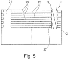
- the heat exchanger 2 is represented in a very schematic way only. It has an inlet-side collecting channel 20 and an outlet-side collecting channel 21 for a first fluid. A number of first fluid channels 22 for the through-flow of the first fluid is provided between the inlet-side collecting channel 20 and the outlet-side collecting channel 21. These are fluidly connected to the inlet-side collecting channel 20 and the outlet-side collecting channel 21.
- second fluid channels 23 are provided, which are provided for the through-flow of a second fluid, wherein there is a heat exchanger between the first fluid and the second fluid.
- the first fluid is in thermal contact with the second fluid.
- Figure 5 also shows that an inventive dip tube 1 is arranged in the inlet-side collecting channel 20 for the distribution of the first fluid to first fluid channels 22.
- the method for producing the heat exchanger 2 is carried out at least with the steps:
- the fluid channels 22, 23 and the collecting channels 20, 21 can be produced as a stacked-plate heat exchanger.
- Alternative designs as a tube fin block with collecting tubes are also possible.
- dip tube 1 is materially connected to the inlet-side collecting channel 20, in particular soldered or glued.
Landscapes
- Engineering & Computer Science (AREA)
- Physics & Mathematics (AREA)
- Thermal Sciences (AREA)
- Mechanical Engineering (AREA)
- General Engineering & Computer Science (AREA)
- Heat-Exchange Devices With Radiators And Conduit Assemblies (AREA)
Abstract
Description
- The invention relates to a heat exchanger with a dip tube, a dip tube and a method for producing a heat exchanger.
- In electric vehicles, and in fuel cell vehicles as well, heat exchangers, for example, are used as stacked-plate heat exchangers, so-called "chillers", by means of which heat is discharged from a coolant to an evaporating refrigerant in order to cool a heat-dissipating component. In doing so, the coolant flows to or through the heat-dissipating component which transfers heat to the coolant. Inside the heat exchanger, the so-called chiller, this absorbed heat is transferred to the evaporating refrigerant. A heat-dissipating component can, e.g., be a rechargeable battery which feeds a drive engine in order to drive the vehicle.
- In particular the fast charging of the vehicle battery as a heat-dissipating component, where large amounts of heat are created within a short time, is a major challenge for the heat exchanger, the so-called chiller. For this case, typically large heat exchangers are required, which have a plurality of fluid channels, which can for example be formed by the plates of a stacked-plate heat exchanger. Fluid channels are formed between plate pairs, wherein the two involved fluids flow in fluid channels of alternating plate pairs.
- The refrigerant flowing into the heat exchanger should be distributed to the fluid channels provided for the refrigerant as a two-phase mixture, with a gas portion and with a liquid portion, so that the portion of the gas phase corresponds as much as possible to the portion of the liquid phase of the two-phase mixture in each fluid channel. If the heat exchanger is designed such that this distribution is reached for the full load case, for example, for example during fast charging, the distribution is different in an off-peak load case.
- If the vehicle is operated in a so-called coasting mode, as an example for an off-peak load case where no or at least not much driving power is required, only little waste heat is created, so that the heat exchanger, the chiller, is operated at a very low load, wherein the mass flow of the refrigerant sinks in this operating state and thus another distribution of the two-phase mixture of the refrigerant is created than during fast charging or at full load of the vehicle, for example.
- There also arises the problem that with different operating states, the two-phase mixture of the refrigerant is present in a different ratio and it is therefore also difficult to evenly distribute the two-phase mixture over the many fluid channels.
- It is the aim of the invention to create a heat exchanger which is improved compared to the state of the art. It is also the aim to create an injection tube for a heat exchanger by means of which a better distribution of a two-phase mixture can be reached also with different operating states. It is also the aim to create a method for producing an injection tube and a method for producing a heat exchanger which are simplified in order to reach a cost-effective production.
- The aim concerning the dip tube is solved with the features of
claim 1. - One exemplary embodiment of the invention relates to a dip tube for a heat exchanger with a circumferential wall, wherein a helicoidal insert is arranged inside the dip tube for the helical fluid conduct of a fluid inside the dip tube and wherein a number of openings is arranged in the wall of the dip tube for the through-flow of the fluid. This can lead to a better distribution of a fluid, which is, in particular, two-phased, such as a refrigerant, to a number of fluid channels, in particular also with different operating states.
- It is also particularly advantageous if the openings in the wall of the dip tube are arranged on one line. Thus, the first fluid can flow in the direction directly to the fluid channels or also in a differing direction, so that the two-phase mixture of the first fluid can be better mixed, if required.
- In embodiment according to the invention, it is also useful if the helicoidal insert has four webs which are wound along the longitudinal direction of the insert and divide the interior space of the dip tube into four partial areas. This enables a better distribution of the first fluid to the fluid channels, where the fluid is more unitarily distributed with an almost equal share of liquid and an almost equal share of vapour at almost all of the openings.
- It is also advantageous if the four webs of the insert are arranged in a cross-shaped manner as seen in section. This enables a simplified production.
- It is also advantageous if the insert is formed of two flat strips which respectively have a longitudinal slot, wherein the strips are inserted into one another in a cross-shaped manner in the area of the longitudinal slots and are afterwards twisted into the helix relative to one another. The twist is created by twisting the respective ends of the strips relative to one another.
- It is also advantageous if the insert is made of plastic or metal and is materially connected to the dip tube, in particular soldered or glued. Thus, a simple and cost-effective production is achieved.
- The aim concerning the heat exchanger is solved with the features of
claim 7. - An example embodiment of the invention relates to a heat exchanger with an inlet-side collecting channel and with an outlet-side collecting channel for a first fluid, wherein a number of first fluid channels for the through-flow of the first fluid is provided between the inlet-side collecting channel and the outlet-side collecting channel and is fluidly connected to the inlet-side collecting channel and the outlet-side collecting channel, further wherein second fluid channels are provided, which are provided for the through-flow of a second fluid, wherein there is a heat exchange between the first fluid and the second fluid, wherein an inventive dip tube is arranged in the inlet-side collecting channel in order to distribute the first fluid to first fluid channels. Thus, a heat exchanger with a better distribution of the first fluid is achieved. It is particularly advantageous if the heat exchanger is an evaporator or a chiller which, on the one side, uses a refrigerant as the first fluid and which, on the other side, uses air or a liquid coolant as the second fluid. For example, R1234yf, R134a, R744 etc. could be used as a refrigerant. For example, a water mixture could be used as a liquid coolant.
- The aim concerning the method for producing a dip tube is solved with the features of
claim 7. - An exemplary embodiment of the invention relates to a method for producing a dip tube, with the steps:
- providing a tube with a circumferential wall,
- incorporating openings in the circumferential wall of the tube,
- providing two flat strips,
- incorporating one respective longitudinal slot up until about the centre of the respective strip,
- telescoping the two strips in the area of their longitudinal slots so that a cross-shaped structure is created,
- twisting the ends of the cross-shaped structure about a central longitudinal axis of the structure so that a helix is created,
- inserting the helix into the tube, and
- connecting the helix to the wall of the tube.
- This prevents the requirement of a complex manufacturing for the production of the helix, wherein a helix can be created from simple elements by the described method.
- It is also particularly advantageous if the openings in the wall of the tube are arranged in one line. This enables a distribution of the first fluid from the respective partial areas of the dip tube.
- It is also advantageous if the helix-shaped insert has four webs which are wound along the longitudinal direction of the insert and divide the interior space of the dip tube into four partial areas, wherein at least one opening is assigned to each partial area. This enables a better formation of the helix and it is easier to distribute the first fluid.
- It is also advantageous if the insert is made of plastic or metal and is materially connected to the tube, in particular soldered or glued. Thus, a simple production can be achieved.
- The aim concerning the method for producing a heat exchanger is solved with the features of
claim 11. - An exemplary embodiment of the invention relates to a method for producing a heat exchanger, with the steps:
- producing an inlet-side collecting channel and an outlet-side collecting channel for a first fluid, wherein a number of first fluid channels for the through-flow of the first fluid is provided between the inlet-side collecting channel and the outlet-side collecting channel and is fluidly connected to the inlet-side collecting channel and the outlet-side collecting channel,
- producing second fluid channels which are provided for the through-flow of a second fluid, and
- arranging a dip tube inside the inlet-side collecting channel.
- In doing so, it is advantageous if the fluid channels and the collecting channels are produced as a stacked-plate heat exchanger. By stacking prepared plates or plate pairs, an efficient production can be achieved. However, variants with a tube fin block and arranged collecting tubes are also possible.
- It is also advantageous if the dip tube is materially connected to the inlet-side collecting channel, in particular soldered or glued.
- Further advantageous designs are described by the following description of the figures and by the dependent claims.
- In the following, the invention will be further explained based on several example embodiments using the drawing figures.
- In the figures:
- Fig. 1
- is a perspective representation of a strip for producing a helix of a dip tube,
- Fig. 2
- is a perspective representation of two strips for producing a helix of a dip tube,
- Fig. 3
- is a perspective representation of a helix of a dip tube,
- Fig. 4
- is a perspective representation of a dip tube with a helix arranged therein, and
- Fig. 5
- is a schematic representation of a heat exchanger with a dip tube.
-
Figure 4 shows adip tube 1 for aheat exchanger 2, seeFigure 5 , with acircumferential wall 3 which is formed by a tube. For this purpose, thetube 4 forming thewall 3 is optionally formed such that it is open at both sides, so that, on the one side, a first fluid can flow into thedip tube 1 at the firstopen end 5. Optionally, however, thesecond end 6 of the dip-tube might be closed. It can also be seen fromFigure 4 that a number ofopenings 7 which serve for the through-flow of the first fluid is arranged in thewall 3 of thedip tube 1. Therefore, the fluid exits the dip-tube through theopenings 7. This leads to a more uniform ratio of liquid and of vapour of the fluid at allopenings 7 such that at almost each opening the ratio between liquid and vapour is comparable. - Only optionally, on the other side, the first fluid can also flow out again at the second
open end 6 too. - It can also be seen that a
helicoidal insert 8, also referred to as a helix, is arranged inside thedip tube 1 for the helical fluid conduct of a first fluid inside thedip tube 1. - In the example embodiment of
Figure 4 , theopenings 7 in thewall 3 of thedip tube 1 are arranged on one line. However, this is optional and theopenings 7 may also be arranged in another way. - It can be seen at the upper end of the
dip tube 1 ofFigure 4 that thehelicoidal insert 8 has fourwebs 9 which are wound along thelongitudinal direction 10 of theinsert 8 and separate theinterior space 11 of thedip tube 1 or of thetube 4 into fourpartial areas 12. - It can also be seen from
Figure 4 that the fourwebs 9 of theinsert 8 are arranged in a cross-shaped manner as seen in section. -
Figures 1 to 3 show that theinsert 8 is formed of twoflat strips 13 which respectively have onelongitudinal slot 14.Figure 1 shows that thelongitudinal slot 14 is aligned along thelongitudinal direction 10 of thestrip 13 and is arranged centrally in the lateral direction. The length of thelongitudinal slot 14 is about half the length of thestrip 13 or a bit more. -
Figure 2 shows that the twostrips 13 are inserted one into another in a cross-shaped manner in the area of thelongitudinal slots 14 and are afterwards twisted into the helix relative to one another. For this purpose, the ends of thestrips 13 are twisted relative to one another so that the helix of theinsert 8 is created from a simple cross-shaped design after telescoping, seeFigure 3 . - Preferably, the
insert 8 is made of plastic or metal and materially connected to thedip tube 1 or to thetube 4 of thedip tube 1, in particular, the helix of theinsert 8 is soldered or glued to thetube 4. - The method for producing the
dip tube 1 included the following steps: - providing a
tube 4 with acircumferential wall 3, - incorporating
openings 7 in thecircumferential wall 3 of thetube 4, - providing two
flat strips 13, - incorporating one respective
longitudinal slot 14 up until about the centre of therespective strip 13, - telescoping the two
strips 13 in the area of theirlongitudinal slots 14 so that a cross-shaped structure is created, - twisting the
ends 15 of the cross-shaped structure about a central longitudinal axis of the structure so that a helix is created as aninsert 8, - inserting the helix into the
tube 4, and - connecting the helix to the
wall 3 of thetube 4 as aninsert 8. - Depending on the example embodiment, the incorporation of the
openings 7 in thewall 3 of thetube 4 is in one line or, alternatively, also in another way. - By inserting the helix-shaped
insert 8 with its fourwebs 9 which are wound along thelongitudinal direction 10 of theinsert 8, theinterior space 11 of thedip tube 1 is divided into fourpartial areas 12, wherein at least oneopening 7 is assigned to eachpartial area 12. - The
dip tube 1 thus formed is then inserted into the inlet-side collecting channel 20 of aheat exchanger 2. - In
Figure 5 , theheat exchanger 2 is represented in a very schematic way only. It has an inlet-side collecting channel 20 and an outlet-side collecting channel 21 for a first fluid. A number of firstfluid channels 22 for the through-flow of the first fluid is provided between the inlet-side collecting channel 20 and the outlet-side collecting channel 21. These are fluidly connected to the inlet-side collecting channel 20 and the outlet-side collecting channel 21. - Further, second
fluid channels 23 are provided, which are provided for the through-flow of a second fluid, wherein there is a heat exchanger between the first fluid and the second fluid. For this purpose, the first fluid is in thermal contact with the second fluid. -
Figure 5 also shows that aninventive dip tube 1 is arranged in the inlet-side collecting channel 20 for the distribution of the first fluid to firstfluid channels 22. - The method for producing the
heat exchanger 2 is carried out at least with the steps: - producing an inlet-
side collecting channel 20 and an outlet-side collecting channel 21 for a first fluid, wherein a number of firstfluid channels 22 for the through-flow of the first fluid is provided between the inlet-side collecting channel 20 and the outlet-side collecting channel 21 and is fluidly connected to the inlet-side collecting channel 20 and the outlet-side collecting channel 21, - producing second
fluid channels 23 which are provided for the through-flow of a second fluid, and - arranging a
dip tube 1 inside the inlet-side collecting channel 20. - In doing so, the
fluid channels channels - It is advantageous if the
dip tube 1 is materially connected to the inlet-side collecting channel 20, in particular soldered or glued.
Claims (13)
- A dip tube (1) for a heat exchanger (2) with a circumferential wall (3), wherein a helicoidal insert (8) is arranged inside the dip tube (1) for the helical fluid conduct of a fluid inside the dip tube (1) and wherein a number of openings (7) is arranged in the wall (3) of the dip tube (1) for the through-flow of the fluid, wherein the helicoidal insert (8) has four webs (9) which are wound along the longitudinal direction (10) of the insert (8) and divide the interior space (11) of the dip tube (1) into four partial areas (12).
- The dip tube (1) according to claim 1, characterised in that the openings (7) in the wall (3) of the dip tube (1) are arranged on one line.
- The dip tube (1) according to claims 1 or 2, characterised in that the four webs (9) of the insert (8) are arranged in a cross-shaped manner as seen in section.
- The dip tube (1) according to claims 1, 2 or 3, characterised in that the insert (8) is formed of two flat strips (13) which respectively have a longitudinal slot (14), wherein the strips (13) are inserted into one another in a cross-shaped manner in the area of the longitudinal slots (14) and are afterwards twisted into the helix relative to one another.
- The dip tube (1) according to claim 4, characterised in that the insert (8) is made of plastic or metal and is materially connected to the dip tube (1), in particular soldered or glued.
- A heat exchanger (2) with an inlet-side collecting channel (20) and with an outlet-side collecting channel (21) for a first fluid, wherein a number of first fluid channels (22) for the through-flow of the first fluid is provided between the inlet-side collecting channel (20) and the outlet-side collecting channel (21) and is fluidly connected to the inlet-side collecting channel (20) and the outlet-side collecting channel (21), further wherein second fluid channels (23) are provided, which are provided for the through-flow of a second fluid, wherein there is a heat exchange between the first fluid and the second fluid, characterised in that a dip tube (1) according to one of the preceding claims is arranged in the inlet-side collecting channel (20) in order to distribute the first fluid to first fluid channels (22).
- A method for producing a dip tube (1) according to one of claims 1 to 5, with the steps:- providing a tube (4) with a circumferential wall (3),- incorporating openings (7) in the circumferential wall (3) of the tube (4),- providing two flat strips (13),- incorporating one respective longitudinal slot (14) up until about the centre of the respective strip (13),- telescoping the two strips (13) in the area of their longitudinal slots (14) so that a cross-shaped structure is created,- twisting the ends of the cross-shaped structure about a central longitudinal axis of the structure so that a helix is created,- inserting the helix into the tube (4), and- connecting the helix to the wall (3) of the tube (4).
- The method according to claim 7, characterised in that the openings (7) in the wall (3) of the tube (4) are arranged in one line.
- The method according to claim 7 or 8, characterised in that the helix-shaped insert (8) has four webs (9) which are wound along the longitudinal direction (10) of the insert (8) and divide the interior space (11) of the dip tube (1) into four partial areas (12), wherein at least one opening (7) is assigned to each partial area (12).
- The method according to claim 7, 8 or 9, characterised in that the insert (8) is made of plastic or metal and is materially connected to the tube (4), in particular soldered or glued.
- A method for producing a dip tube (2) according to claim 6, with the steps:- producing an inlet-side collecting channel (20) and an outlet-side collecting channel (21) for a first fluid, wherein a number of first fluid channels (22) for the through-flow of the first fluid is provided between the inlet-side collecting channel (20) and the outlet-side collecting channel (21) and is fluidly connected to the inlet-side collecting channel (20) and the outlet-side collecting channel (21),- producing second fluid channels (23) which are provided for the through-flow of a second fluid, and- arranging a dip tube (1) according to one of claims 1 to 6 inside the inlet-side collecting channel (20).
- The method according to claim 11, characterised in that the fluid channels (22, 23) and the collecting channels (20, 21) are produced as a stacked-plate heat exchanger.
- The method according to claim 11 or 12, characterised in that the dip tube (1) is materially connected to the inlet-side collecting channel (20), in particular soldered or glued.
Priority Applications (1)
| Application Number | Priority Date | Filing Date | Title |
|---|---|---|---|
| EP19185722.6A EP3764050A1 (en) | 2019-07-11 | 2019-07-11 | Heat exchanger, dip tube and method for producing the same |
Applications Claiming Priority (1)
| Application Number | Priority Date | Filing Date | Title |
|---|---|---|---|
| EP19185722.6A EP3764050A1 (en) | 2019-07-11 | 2019-07-11 | Heat exchanger, dip tube and method for producing the same |
Publications (1)
| Publication Number | Publication Date |
|---|---|
| EP3764050A1 true EP3764050A1 (en) | 2021-01-13 |
Family
ID=67253746
Family Applications (1)
| Application Number | Title | Priority Date | Filing Date |
|---|---|---|---|
| EP19185722.6A Withdrawn EP3764050A1 (en) | 2019-07-11 | 2019-07-11 | Heat exchanger, dip tube and method for producing the same |
Country Status (1)
| Country | Link |
|---|---|
| EP (1) | EP3764050A1 (en) |
Citations (4)
| Publication number | Priority date | Publication date | Assignee | Title |
|---|---|---|---|---|
| JP2006336890A (en) * | 2005-05-31 | 2006-12-14 | Calsonic Kansei Corp | Intercooler |
| JP5759068B2 (en) * | 2012-05-17 | 2015-08-05 | 三菱電機株式会社 | Heat exchanger and refrigeration cycle apparatus |
| WO2018206670A1 (en) * | 2017-05-10 | 2018-11-15 | Valeo Systemes Thermiques | Heat exchanger that forms part of a refrigerant circuit |
| FR3066263A1 (en) * | 2017-05-10 | 2018-11-16 | Valeo Systemes Thermiques | COLLECTOR COMPRISING A BATTERY COOLER EQUIPPED WITH A MOTOR VEHICLE |
-
2019
- 2019-07-11 EP EP19185722.6A patent/EP3764050A1/en not_active Withdrawn
Patent Citations (4)
| Publication number | Priority date | Publication date | Assignee | Title |
|---|---|---|---|---|
| JP2006336890A (en) * | 2005-05-31 | 2006-12-14 | Calsonic Kansei Corp | Intercooler |
| JP5759068B2 (en) * | 2012-05-17 | 2015-08-05 | 三菱電機株式会社 | Heat exchanger and refrigeration cycle apparatus |
| WO2018206670A1 (en) * | 2017-05-10 | 2018-11-15 | Valeo Systemes Thermiques | Heat exchanger that forms part of a refrigerant circuit |
| FR3066263A1 (en) * | 2017-05-10 | 2018-11-16 | Valeo Systemes Thermiques | COLLECTOR COMPRISING A BATTERY COOLER EQUIPPED WITH A MOTOR VEHICLE |
Similar Documents
| Publication | Publication Date | Title |
|---|---|---|
| EP0930477B1 (en) | Liquid cooled, two phase heat exchanger | |
| EP0563471B1 (en) | Evaporator | |
| KR101338283B1 (en) | Multi-channel heat exchanger with improved uniformity of refrigerant fluid distribution | |
| US7527087B2 (en) | Heat exchanger | |
| EP2556320B1 (en) | Heat exchanger | |
| US20080185130A1 (en) | Heat exchanger with extruded cooling tubes | |
| EP2175223A1 (en) | Refrigerant evaporator | |
| DE112019003711B4 (en) | Integrated liquid/air cooled condenser and low temperature cooler | |
| EP1365200A1 (en) | Multistage gas and liquid phase separation condenser | |
| JP5768480B2 (en) | Cold storage heat exchanger | |
| JP2003121092A (en) | Heat exchanger | |
| DE112012004988T5 (en) | heat exchangers | |
| CN112005074B (en) | Refrigerant distributors, heat exchangers and air conditioners | |
| KR20110021789A (en) | Heat exchanger with heat exchange chamber using each medium guide member | |
| US20160084548A1 (en) | Refrigerant evaporator | |
| US9807915B2 (en) | Heat exchanger for cooling electric element | |
| JP6183100B2 (en) | Cold storage heat exchanger | |
| DE102016100192B4 (en) | Device for heat transfer | |
| EP2653329A1 (en) | Evaporator for air conditioning with phase change material for a thermal syphon operation mode | |
| CN216977245U (en) | Heat exchanger and air conditioner | |
| JP2001147095A (en) | Heat exchanger | |
| JP2010151381A (en) | Evaporator | |
| KR20050061454A (en) | Flat tube and process for producing heat exchanger with use of the flat tube | |
| CN114041035A (en) | CCF heater core subassembly | |
| US20140054016A1 (en) | Condenser |
Legal Events
| Date | Code | Title | Description |
|---|---|---|---|
| PUAI | Public reference made under article 153(3) epc to a published international application that has entered the european phase |
Free format text: ORIGINAL CODE: 0009012 |
|
| STAA | Information on the status of an ep patent application or granted ep patent |
Free format text: STATUS: THE APPLICATION HAS BEEN PUBLISHED |
|
| AK | Designated contracting states |
Kind code of ref document: A1 Designated state(s): AL AT BE BG CH CY CZ DE DK EE ES FI FR GB GR HR HU IE IS IT LI LT LU LV MC MK MT NL NO PL PT RO RS SE SI SK SM TR |
|
| AX | Request for extension of the european patent |
Extension state: BA ME |
|
| STAA | Information on the status of an ep patent application or granted ep patent |
Free format text: STATUS: REQUEST FOR EXAMINATION WAS MADE |
|
| STAA | Information on the status of an ep patent application or granted ep patent |
Free format text: STATUS: EXAMINATION IS IN PROGRESS |
|
| 17P | Request for examination filed |
Effective date: 20210713 |
|
| RBV | Designated contracting states (corrected) |
Designated state(s): AL AT BE BG CH CY CZ DE DK EE ES FI FR GB GR HR HU IE IS IT LI LT LU LV MC MK MT NL NO PL PT RO RS SE SI SK SM TR |
|
| 17Q | First examination report despatched |
Effective date: 20210803 |
|
| STAA | Information on the status of an ep patent application or granted ep patent |
Free format text: STATUS: THE APPLICATION IS DEEMED TO BE WITHDRAWN |
|
| 18D | Application deemed to be withdrawn |
Effective date: 20220215 |