EP3763952A1 - Barrel nut retainer with one-way installation guide - Google Patents
Barrel nut retainer with one-way installation guide Download PDFInfo
- Publication number
- EP3763952A1 EP3763952A1 EP19212416.2A EP19212416A EP3763952A1 EP 3763952 A1 EP3763952 A1 EP 3763952A1 EP 19212416 A EP19212416 A EP 19212416A EP 3763952 A1 EP3763952 A1 EP 3763952A1
- Authority
- EP
- European Patent Office
- Prior art keywords
- tab
- barrel nut
- fastener
- base
- port
- Prior art date
- Legal status (The legal status is an assumption and is not a legal conclusion. Google has not performed a legal analysis and makes no representation as to the accuracy of the status listed.)
- Granted
Links
Images



Classifications
-
- F—MECHANICAL ENGINEERING; LIGHTING; HEATING; WEAPONS; BLASTING
- F16—ENGINEERING ELEMENTS AND UNITS; GENERAL MEASURES FOR PRODUCING AND MAINTAINING EFFECTIVE FUNCTIONING OF MACHINES OR INSTALLATIONS; THERMAL INSULATION IN GENERAL
- F16B—DEVICES FOR FASTENING OR SECURING CONSTRUCTIONAL ELEMENTS OR MACHINE PARTS TOGETHER, e.g. NAILS, BOLTS, CIRCLIPS, CLAMPS, CLIPS OR WEDGES; JOINTS OR JOINTING
- F16B37/00—Nuts or like thread-engaging members
- F16B37/04—Devices for fastening nuts to surfaces, e.g. sheets, plates
- F16B37/045—Devices for fastening nuts to surfaces, e.g. sheets, plates specially adapted for fastening in channels, e.g. sliding bolts, channel nuts
- F16B37/047—Barrel nuts
-
- F—MECHANICAL ENGINEERING; LIGHTING; HEATING; WEAPONS; BLASTING
- F16—ENGINEERING ELEMENTS AND UNITS; GENERAL MEASURES FOR PRODUCING AND MAINTAINING EFFECTIVE FUNCTIONING OF MACHINES OR INSTALLATIONS; THERMAL INSULATION IN GENERAL
- F16B—DEVICES FOR FASTENING OR SECURING CONSTRUCTIONAL ELEMENTS OR MACHINE PARTS TOGETHER, e.g. NAILS, BOLTS, CIRCLIPS, CLAMPS, CLIPS OR WEDGES; JOINTS OR JOINTING
- F16B37/00—Nuts or like thread-engaging members
- F16B37/04—Devices for fastening nuts to surfaces, e.g. sheets, plates
- F16B37/044—Nut cages
-
- F—MECHANICAL ENGINEERING; LIGHTING; HEATING; WEAPONS; BLASTING
- F16—ENGINEERING ELEMENTS AND UNITS; GENERAL MEASURES FOR PRODUCING AND MAINTAINING EFFECTIVE FUNCTIONING OF MACHINES OR INSTALLATIONS; THERMAL INSULATION IN GENERAL
- F16B—DEVICES FOR FASTENING OR SECURING CONSTRUCTIONAL ELEMENTS OR MACHINE PARTS TOGETHER, e.g. NAILS, BOLTS, CIRCLIPS, CLAMPS, CLIPS OR WEDGES; JOINTS OR JOINTING
- F16B37/00—Nuts or like thread-engaging members
- F16B37/04—Devices for fastening nuts to surfaces, e.g. sheets, plates
- F16B37/045—Devices for fastening nuts to surfaces, e.g. sheets, plates specially adapted for fastening in channels, e.g. sliding bolts, channel nuts
- F16B37/046—Devices for fastening nuts to surfaces, e.g. sheets, plates specially adapted for fastening in channels, e.g. sliding bolts, channel nuts with resilient means for urging the nut inside the channel
-
- F—MECHANICAL ENGINEERING; LIGHTING; HEATING; WEAPONS; BLASTING
- F16—ENGINEERING ELEMENTS AND UNITS; GENERAL MEASURES FOR PRODUCING AND MAINTAINING EFFECTIVE FUNCTIONING OF MACHINES OR INSTALLATIONS; THERMAL INSULATION IN GENERAL
- F16B—DEVICES FOR FASTENING OR SECURING CONSTRUCTIONAL ELEMENTS OR MACHINE PARTS TOGETHER, e.g. NAILS, BOLTS, CIRCLIPS, CLAMPS, CLIPS OR WEDGES; JOINTS OR JOINTING
- F16B39/00—Locking of screws, bolts or nuts
- F16B39/22—Locking of screws, bolts or nuts in which the locking takes place during screwing down or tightening
- F16B39/24—Locking of screws, bolts or nuts in which the locking takes place during screwing down or tightening by means of washers, spring washers, or resilient plates that lock against the object
-
- F—MECHANICAL ENGINEERING; LIGHTING; HEATING; WEAPONS; BLASTING
- F16—ENGINEERING ELEMENTS AND UNITS; GENERAL MEASURES FOR PRODUCING AND MAINTAINING EFFECTIVE FUNCTIONING OF MACHINES OR INSTALLATIONS; THERMAL INSULATION IN GENERAL
- F16B—DEVICES FOR FASTENING OR SECURING CONSTRUCTIONAL ELEMENTS OR MACHINE PARTS TOGETHER, e.g. NAILS, BOLTS, CIRCLIPS, CLAMPS, CLIPS OR WEDGES; JOINTS OR JOINTING
- F16B41/00—Measures against loss of bolts, nuts, or pins; Measures against unauthorised operation of bolts, nuts or pins
- F16B41/002—Measures against loss of bolts, nuts or pins
Definitions
- This disclosure relates generally to a mechanical coupling and, more particularly, to a mechanical coupling using a barrel nut and a barrel nut retainer.
- the barrel nut coupling system may include a bolt, a barrel nut and a barrel nut retainer. During assembly, the barrel nut retainer is mated with the barrel nut. These mated elements are inserted together into a receptacle in the second component. A shank of the bolt is then sequentially passed through bolt holes in the first and the second components and threaded into a threaded aperture of the barrel nut.
- the fastener may be threaded into the threaded aperture along a first direction or along an opposite second direction.
- the barrel nut In the first direction, the barrel nut may be located between the second component and the barrel nut retainer. The barrel nut may thereby contact and be pressed directly against the second component.
- the barrel nut retainer in the second direction, may be located between the second component and the barrel nut. The barrel nut retainer may thereby be sandwiched between the barrel nut and the second component.
- an assembly includes a barrel nut, a barrel nut retainer and a fastener.
- the barrel nut includes a threaded aperture.
- the barrel nut retainer includes a one-way installation guide.
- the fastener is configured to thread into the threaded aperture.
- the fastener is further configured to pass through the threaded aperture and project into the one-way installation guide when the fastener is inserted into the barrel nut retainer along a first direction.
- another assembly includes a barrel nut, a barrel nut retainer and a fastener.
- the barrel nut includes a threaded aperture.
- the barrel nut retainer is abutted against the barrel nut.
- the barrel nut retainer includes a tubular base and a tab connected to a sidewall of the tubular base. The tab projects into a port in the sidewall of the tubular base.
- the fastener includes a shank and a head. The shank is threaded into the threaded aperture. The shank projects out from the head, through the threaded aperture, to a distal end portion of the shank that engages the tab.
- a coupling assembly includes a barrel nut retainer that includes a tubular sidewall, a first flange, a second flange and a tab.
- the tubular sidewall is configured with a first port and a second port.
- the first port extends along an axis through the tubular sidewall at a first side of the tubular sidewall.
- the second port extends along the axis through the tubular sidewall at a second side of the tubular sidewall.
- the first flange and the second flange project out from the first side of the tubular sidewall.
- the first port is located laterally between the first flange and the second flange.
- the tab projects into the second port from the tubular sidewall.
- the barrel nut retainer may be formed as a monolithic body.
- the barrel nut retainer may be formed from multiple different bodies that are attached together.
- the one-way installation guide may be configured to prevent the fastener from projecting into the one-way installation guide when the fastener is inserted into the barrel nut retainer along a second direction that is opposite the first direction.
- the one-way installation guide may be configured as or otherwise include a tab.
- the tab may be configured to bend and then slide along the fastener when the fastener is inserted into the barrel nut retainer along the first direction.
- the tab may also or alternatively be configured to block passage of the fastener into the one-way installation guide when the fastener is inserted into the barrel nut retainer along a second direction that is opposite the first direction.
- the tab may have a hooked configuration.
- the barrel nut retainer may also include a base with a port.
- the tab may project out from the base into the port.
- the tab may have a distal end.
- the tab may project away from the base to the distal end along a trajectory comprising a component along the first direction.
- the one-way installation guide may also include a second tab.
- the second tab may project out from the base into the port.
- a diameter of the fastener may be greater than a distance between the tab and the second tab.
- the base may be a tubular base.
- the port may extend through a sidewall of the tubular base.
- the base may further include a first flange and a second flange.
- the barrel nut may be abutted against the base and may be located laterally between the first flange and the second flange.
- the tab may include a base portion and an end portion connected to the base portion at a corner.
- the end portion may be angularly offset from the base portion by an acute included angle.
- the one-way installation guide may also include a second tab.
- the second tab may be diametrically opposed from the tab.
- the assembly may also include a first component and a second component.
- the first component may be configured with or otherwise include a first fastener aperture.
- the second component may be configured with or otherwise include a second fastener aperture and a receptacle.
- the second component may be abutted against the first component.
- the barrel nut and the barrel nut retainer may be arranged within the receptacle.
- the fastener may extend sequentially through the first fastener aperture, the second fastener aperture and the threaded aperture and then may project into the one-way installation guide when the fastener is inserted into the barrel nut retainer along the first direction.
- the assembly may include an aircraft propulsion system structure that includes the first component and the second component.
- the tab may be configured to bend and then slide along the shank when the shank is inserted into the barrel nut retainer along a first direction.
- the tab may also or alternatively be configured to block passage of the shank into the port when the shank is inserted into the barrel nut retainer along a second direction that is opposite the first direction.
- the barrel nut retainer may also include a second tab.
- the second tab may project into the port in the sidewall of the tubular base.
- a diameter of the shank may be greater than a distance between the tab and the second tab.
- FIG. 1 is a perspective sectional illustration of a portion of an assembly 20.
- This assembly 20 includes a first component 22, a second component 24 and a barrel nut coupling system 26 for connecting the first component 22 and the second component 24 together.
- the first component 22 is configured with a first fastener aperture 28; e.g., a substantially cylindrical through-hole.
- This first fastener aperture 28 extends axially along an axis 30 (e.g., a centerline of the first fastener aperture 28) through the first component 22 between opposing first component surfaces 32 and 34 of the first component 22.
- the second component 24 is configured with a second fastener aperture 36 (e.g., a substantially cylindrical through-hole) and a receptacle 38 (e.g., a substantially cylindrical blind hole).
- the second fastener aperture 36 extends axially along the axis 30 (e.g., a centerline of the second fastener aperture 36) through the second component 24 between opposing second component surfaces 40 and 42 of the second component 24.
- the second component surface 42 extends circumferentially around a centerline 44, which centerline 44 of FIG. 1 is perpendicular to and coincident with the axis 30. This second component surface 42 forms a circumferential periphery of the receptacle 38.
- the receptacle 38 may extend longitudinally along the centerline 44 through the second component 24.
- the coupling system 26 includes a fastener 48, a barrel nut 50 and a barrel nut retainer 52.
- the coupling system 26 of FIG. 1 also includes a washer 54.
- the fastener 48 may be configured as a bolt.
- the fastener 48 of FIG. 1 includes a head 56 and a shank 58.
- the shank 58 projects axially along the axis 30 (e.g., a centerline of the shank 58 / fastener 48) out from the head 56 to a distal end 60 of the fastener 48. At least an end portion or an entirety of a length of the shank 58 is threaded.
- the barrel nut 50 may be configured with a partially cylindrical body 62.
- the barrel nut 50 of FIGS. 3 and 4 includes a curved side surface 64, a second (e.g., planar) side surface 66 and opposing end (e.g., planar) surfaces 68 and 70.
- the curved side surface 64 of FIG. 4 is a partially cylindrical surface. This curved side surface 64 extends circumferentially about a centerline 72 from a first edge of the second side surface 66 to an opposing second edge of the second side surface 66.
- the centerline 72 may be coaxial with the centerline 44 of the receptacle 38 (see FIG. 1 ) when mated with the receptacle 38 as described below.
- the curved side surface 64 and the second side surface 66 each extends longitudinally along the centerline 72 between the end surfaces 68 and 70.
- the barrel nut 50 may also include a protrusion 74; e.g., a cylindrical protrusion or rim.
- This protrusion 74 projects axially along the axis 30 (e.g., a centerline of the protrusion 74) out from the barrel nut body 62 and its second side surface 66 to a distal end 76 of the protrusion 74.
- the barrel nut 50 is configured with a threaded aperture 78.
- This threaded aperture 78 extends axially along the axis 30 (e.g., a centerline of the threaded aperture 78) through the barrel nut body 62 and the protrusion 74 between the curved side surface 64 and the distal end 76 of the protrusion 74.
- the barrel nut retainer 52 includes a (e.g., tubular) retainer base 80, one or more flanges 82A and 82B (generally referred to as "82") and a one-way installation guide 84; e.g., a one-way fastener gate.
- a (e.g., tubular) retainer base 80 one or more flanges 82A and 82B (generally referred to as "82") and a one-way installation guide 84; e.g., a one-way fastener gate.
- the retainer base 80 is configured with a tubular sidewall 86.
- This tubular sidewall 86 is formed by one or more sidewall portions.
- These sidewall portions include opposing curved side portions 88A and 88B (generally referred to as "88") and opposing (e.g., planar) interior and exterior side portions 90 and 92. Each of these side portions 88 extends laterally between opposing ends of the retainer base 80.
- Each of the curved side portions 88 of FIG. 6 is a partially cylindrical portion.
- the first curved side portion 88A extends circumferentially about a centerline 94A from a first edge of the interior side portion 90 to a first edge of the exterior side portion 92.
- the second curved side portion 88B extends circumferentially about a centerline 94B from a second edge of the interior side portion 90 to a second edge of the exterior side portion 92.
- the centerlines 94A and 94B may be parallel but separated as illustrated in FIG. 6 . Alternatively, the centerlines 94A and 94B may be coaxial in other embodiments.
- the interior side portion 90 is disposed at an interior side 96 of the retainer base 80.
- the interior side portion 90 is configured with an interior side port 98; e.g., a circular through-hole or alternatively a non-circular (e.g., oval) through-hole.
- This interior side port 98 extends axially along the axis 30 (e.g., a centerline of the interior side port 98) through the tubular sidewall 86 and its interior side portion 90.
- the interior side portion 90 also includes a slot 100.
- This slot 100 separates the interior side portion 90 into two halves and enables the barrel nut retainer 52 to be formed from a piece of cut and bent sheet material; e.g., sheet metal.
- the slot 100 may also enable resilient flexure of the retainer base 80.
- the exterior side portion 92 is disposed at an exterior side 102 of the retainer base 80, which exterior side 102 is diametrically opposed to the interior side portion 90.
- the exterior side portion 92 is configured with an exterior side port 104; e.g., a through hole.
- This exterior side port 104 extends axially along the axis 30 (e.g., a centerline of the exterior side port 104) through the tubular sidewall 86 and its exterior side portion 92.
- the exterior side port 104 has a non-circular geometry; e.g., a generally diamond-shaped geometry.
- the present disclosure is not limited to such an exemplary exterior side port geometry.
- the exterior side port 104 may have a circular, oval, square, rectangular or any other suitable geometry.
- one or more of the flanges 82 such as a pair of first flanges 82A are disposed at (e.g., one, adjacent or proximate) a first end 106A of the retainer base 80. These first flanges 82A are disposed on opposing sides of the slot 100.
- One or more of the flanges 82 such as a pair of second flanges 82B are disposed at (e.g., on, adjacent or proximate) a second end 106B of the retainer base 80.
- the second flanges 82B are disposed on opposing sides of the slot 100.
- Each of the flanges 82 projects out from the retainer base 80 and its interior side portion 90.
- Each of the flanges 82 is arranged perpendicular to the interior side portion 90; e.g., parallel to the axis 30.
- the one-way installation guide 84 is configured to enable the fastener 48 to properly mate with the barrel nut retainer 52 when inserted into the barrel nut retainer 52 along a first direction 108, relative to the retainer 52, along the axis 30.
- the one-way installation guide 84 is configured to prevent the fastener 48 from mating with the barrel nut retainer 52 when inserted into the barrel nut retainer 52 along a second direction 110, relative to the retainer 52, along the axis 30, which second direction 110 is opposite the first direction 108.
- the one-way installation guide 84 may prevent improper assembly of the coupling system 26 as described below.
- the one-way installation guide 84 of FIGS. 5-7 includes one or more tabs 112A and 112B (generally referred to as "112").
- the tabs 112 are arranged on opposing sides of the exterior side port 104; e.g., diametrically disposed.
- Each of the tabs 112 is cantilevered from the retainer base 80 at the exterior side 102. More particularly, each tab 112A, 112B projects out from the exterior side portion 92, into the exterior side port 104, to a distal end 114A, 114B of that tab 112A, 112B. Each tab 112 may have a hooked (e.g., J-shaped, U-shaped or V-shaped) configuration.
- Each tab 112A, 112B of FIG. 7 for example, includes base portion 116A, 116B and an end portion 118A, 118B connected to the base portion 116A, 116B at a corner 120A, 120B; e.g., an intermediate radiused portion of the tab.
- the base portion 116A, 116B extends along a first trajectory from the exterior side portion 92 to the corner 120A, 120B.
- This first trajectory includes an axial component in the second direction 110.
- the first trajectory also includes a radial inward component relative to the axis 30.
- the first trajectory of FIG. 7 is a substantially straight-line trajectory. However, in other embodiments, the first trajectory may be a curved or otherwise non-straight-line trajectory.
- the end portion 118A, 118B extends along a second trajectory from the corner 120A, 120B to the distal end 114A, 114B of that tab 112A, 112B.
- This second trajectory includes an axial component in the first direction 108.
- the second trajectory also includes a radial inward component relative to the axis 30.
- the second trajectory of FIG. 7 is a substantially straight-line trajectory. However, in other embodiments, the second trajectory may be a curved or otherwise non-straight-line trajectory.
- the end portion 118A, 118B is angularly offset from the base portion 116A, 116B by an included angle 122A, 122B.
- This included angle 122A, 122B may be an acute angle such as, for example, between five (5) and sixty (60) degrees.
- the present disclosure is not limited to such exemplary included angle values.
- the distal ends 114A and 114B of the tabs 112A and 112B are separated by a (e.g., minimum) distance 124 when the tabs 112A and 112B are in a relaxed state; e.g., when the fastener 48 is not bending the tabs 112A and 112B as described below.
- This distance 124 is sized to be less than a (e.g., maximum or minimum) diameter 126 of the shank 58 of the fastener 48.
- the barrel nut 50 is mated with the barrel nut retainer 52 as shown in FIG. 8 .
- the protrusion 74 projects axially through the interior side port 98.
- the second side surface 66 is abutted against and may contact the interior side portion 90.
- the barrel nut body 62 is located laterally between the first and the second flanges 82A and 82B (82A not visible in FIG. 8 ).
- the first end surface 68 may abut against and contact one or each of the first flanges 82A.
- the second end surface 70 may also or alternatively abut against and contact one or each of the second flanges 82B.
- the flanges 82 are thereby operable to laterally lock the barrel nut 50 to the barrel nut retainer 52.
- the flanges 82 may also serve as anti-rotation features to prevent rotation between the elements 50 and 52.
- the mated elements 50 and 52 are inserted into the receptacle 38.
- the first component 22 is arranged with the second component 24.
- the first component surface 34 for example, may be abutted against the second component surface 40.
- the fastener 48 is mated with the washer 54.
- the shank 58 is inserted into a bore of the washer 54.
- the shank 58 is subsequently mated with the first component 22, the second component 24, the barrel nut 50 and the barrel nut retainer 52.
- the shank 58 of the fastener 48 is inserted into and passed sequentially through the first fastener aperture 28, the second fastener aperture 36 and the threaded aperture 78 (e.g., threaded into the threaded aperture 78) and then inserted into the one-way installation guide 84.
- the distal end 60 of the shank 58 is operable to push radially outwards against the end portions 118A and 118B of the tabs 112A and 112B such that the distal ends 114A and 114B move radially outward; e.g., away from one another.
- the shank 58 thereby bends the tabs 112 in a radially outward direction and the distance 124 (see FIG. 7 ) increases.
- an end portion of the shank 58 is operable to slide against and pass between the tabs 112.
- the distal ends 114A and 114B of the tabs 112A and 112B are operable to block the distal end 60 of the shank 58 from passing between the tabs 112A and 112B.
- the tabs 112 are thereby operable to prevent the fastener 48 from projecting into the one-way installation guide 84.
- the head 56 and the washer 54 will not be abutted against the first component surface 34 (see FIG. 1 ), and a person assembling the coupling system 26 may be alerted that the barrel nut 50 and the barrel nut retainer 52 were inserted upside-down within the receptacle 38. This type of alert may be particularly useful where the receptacle 38 is visually blocked by one or more other adjacent elements.
- the barrel nut retainer 52 and its one-way installation guide 84 may have various configurations other than that described above.
- the one-way installation guide 84 may be configured with a single tab 112 or more than two tabs 112.
- One or more or each of the tabs 112 may have a planar configuration as shown, for example, in FIG. 10 .
- the curved side portions 88 and the exterior side portion 92 may be configured into a single curved side portion 92' as shown, for example, in FIG. 11 .
- One or more of the flanges 82A and/or 82B may be omitted.
- the slot 100 may be filled with weld and/or the halves of the interior side portion 90 may be otherwise connected.
- the present disclosure therefore is not limited to the foregoing exemplary barrel nut retainer 52 and one-way installation guide 84 configurations.
- the barrel nut retainer 52 may be formed as a monolithic body.
- the term "monolithic body" is used herein to describe a single, unitary body formed (e.g., machined and shaped) as a single mass of material.
- the barrel nut retainer 52 may be formed from a single cut and folded sheet of material; e.g., sheet metal.
- the barrel nut retainer 52 may be formed from multiple bodies that are mechanically fastened, bonded (e.g., welded, brazed and/or adhered) and/or otherwise attached together.
- the retainer base 80 and the flanges 82 may be formed together as a single body.
- the tabs 112 may be separately formed and subsequently may be attached to the retainer base 80.
- the flanges 82 may also or alternatively be separately formed and may subsequently be attached to the retainer base 80.
- FIG. 12 is a partial illustration of an aircraft propulsion system structure 128.
- This structure 128 includes an engine mounting beam 130 and a pylon fitting 132; e.g., a pylon adaptor beam.
- the first component 22 of FIG. 1 may be configured as the engine mounting beam 130.
- the second component 24 of FIG. 1 may be configured as the pylon fitting 132.
- the present disclosure is not limited to such an exemplary configuration nor to aircraft propulsion system applications.
Landscapes
- Engineering & Computer Science (AREA)
- General Engineering & Computer Science (AREA)
- Mechanical Engineering (AREA)
- Connection Of Plates (AREA)
Abstract
Description
- This disclosure relates generally to a mechanical coupling and, more particularly, to a mechanical coupling using a barrel nut and a barrel nut retainer.
- It is known to use a barrel nut coupling system to connect a first component to a second component. The barrel nut coupling system may include a bolt, a barrel nut and a barrel nut retainer. During assembly, the barrel nut retainer is mated with the barrel nut. These mated elements are inserted together into a receptacle in the second component. A shank of the bolt is then sequentially passed through bolt holes in the first and the second components and threaded into a threaded aperture of the barrel nut.
- The fastener may be threaded into the threaded aperture along a first direction or along an opposite second direction. In the first direction, the barrel nut may be located between the second component and the barrel nut retainer. The barrel nut may thereby contact and be pressed directly against the second component. By contrast, in the second direction, the barrel nut retainer may be located between the second component and the barrel nut. The barrel nut retainer may thereby be sandwiched between the barrel nut and the second component. As a result, when the bolt is tightened, (a) the bolt, the barrel nut, barrel nut retainer and/or the second component may be damaged due to improper seating of the barrel nut and/or (b) the bolt may be tightened to an inaccurate torque due to, for example, possible elastic deformation of the barrel nut retainer. There is a need in the art therefore for an improved barrel nut coupling system that prevents or reduces likelihood of improper mating of a fastener with a barrel nut.
- According to an aspect of the present disclosure, an assembly is provided that includes a barrel nut, a barrel nut retainer and a fastener. The barrel nut includes a threaded aperture. The barrel nut retainer includes a one-way installation guide. The fastener is configured to thread into the threaded aperture. The fastener is further configured to pass through the threaded aperture and project into the one-way installation guide when the fastener is inserted into the barrel nut retainer along a first direction.
- According to another aspect of the present disclosure, another assembly is provided that includes a barrel nut, a barrel nut retainer and a fastener. The barrel nut includes a threaded aperture. The barrel nut retainer is abutted against the barrel nut. The barrel nut retainer includes a tubular base and a tab connected to a sidewall of the tubular base. The tab projects into a port in the sidewall of the tubular base. The fastener includes a shank and a head. The shank is threaded into the threaded aperture. The shank projects out from the head, through the threaded aperture, to a distal end portion of the shank that engages the tab.
- According to still another aspect of the present disclosure, a coupling assembly is provided that includes a barrel nut retainer that includes a tubular sidewall, a first flange, a second flange and a tab. The tubular sidewall is configured with a first port and a second port. The first port extends along an axis through the tubular sidewall at a first side of the tubular sidewall. The second port extends along the axis through the tubular sidewall at a second side of the tubular sidewall. The first flange and the second flange project out from the first side of the tubular sidewall. The first port is located laterally between the first flange and the second flange. The tab projects into the second port from the tubular sidewall.
- The barrel nut retainer may be formed as a monolithic body.
- The barrel nut retainer may be formed from multiple different bodies that are attached together.
- The one-way installation guide may be configured to prevent the fastener from projecting into the one-way installation guide when the fastener is inserted into the barrel nut retainer along a second direction that is opposite the first direction.
- The one-way installation guide may be configured as or otherwise include a tab.
- The tab may be configured to bend and then slide along the fastener when the fastener is inserted into the barrel nut retainer along the first direction. The tab may also or alternatively be configured to block passage of the fastener into the one-way installation guide when the fastener is inserted into the barrel nut retainer along a second direction that is opposite the first direction.
- The tab may have a hooked configuration.
- The barrel nut retainer may also include a base with a port. The tab may project out from the base into the port.
- The tab may have a distal end. The tab may project away from the base to the distal end along a trajectory comprising a component along the first direction.
- The one-way installation guide may also include a second tab. The second tab may project out from the base into the port. A diameter of the fastener may be greater than a distance between the tab and the second tab.
- The base may be a tubular base. The port may extend through a sidewall of the tubular base.
- The base may further include a first flange and a second flange. The barrel nut may be abutted against the base and may be located laterally between the first flange and the second flange.
- The tab may include a base portion and an end portion connected to the base portion at a corner. The end portion may be angularly offset from the base portion by an acute included angle.
- The one-way installation guide may also include a second tab.
- The second tab may be diametrically opposed from the tab.
- The assembly may also include a first component and a second component. The first component may be configured with or otherwise include a first fastener aperture. The second component may be configured with or otherwise include a second fastener aperture and a receptacle. The second component may be abutted against the first component. The barrel nut and the barrel nut retainer may be arranged within the receptacle. The fastener may extend sequentially through the first fastener aperture, the second fastener aperture and the threaded aperture and then may project into the one-way installation guide when the fastener is inserted into the barrel nut retainer along the first direction.
- The assembly may include an aircraft propulsion system structure that includes the first component and the second component.
- The tab may be configured to bend and then slide along the shank when the shank is inserted into the barrel nut retainer along a first direction. The tab may also or alternatively be configured to block passage of the shank into the port when the shank is inserted into the barrel nut retainer along a second direction that is opposite the first direction.
- The barrel nut retainer may also include a second tab. The second tab may project into the port in the sidewall of the tubular base. A diameter of the shank may be greater than a distance between the tab and the second tab.
- The foregoing features and the operation of the invention will become more apparent in light of the following description and the accompanying drawings.
-
-
FIG. 1 is a perspective side sectional illustration of a portion of an assembly with a barrel nut coupling system. -
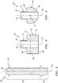
FIG. 2 is a side sectional illustration of a fastener. -
FIG. 3 is a side sectional illustration of a barrel nut. -
FIG. 4 is a cross-sectional illustration of the barrel nut. -
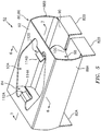
FIG. 5 is a perspective illustration of a barrel nut retainer. -
FIG. 6 is a cross-sectional illustration of the barrel nut retainer taken along line 6-6 inFIG. 5 . -
FIG. 7 is a side sectional illustration of the barrel nut retainer taken along line 7-7 inFIG. 5 . -
FIG. 8 is a perspective side sectional illustration of a portion of the barrel nut coupling system with the fastener inserted into the barrel nut retainer along a first direction. -
FIG. 9 is a perspective side sectional illustration of a portion of the barrel nut coupling system with the fastener inserted into the barrel nut retainer along a second direction. -
FIG. 10 is a perspective illustration of another barrel nut retainer. -
FIG. 11 is an end view illustration of still another barrel nut retainer. -
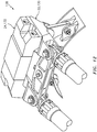
FIG. 12 is a perspective illustration of a portion of an aircraft propulsion system structure. -
FIG. 1 is a perspective sectional illustration of a portion of anassembly 20. Thisassembly 20 includes afirst component 22, asecond component 24 and a barrelnut coupling system 26 for connecting thefirst component 22 and thesecond component 24 together. - The
first component 22 is configured with afirst fastener aperture 28; e.g., a substantially cylindrical through-hole. Thisfirst fastener aperture 28 extends axially along an axis 30 (e.g., a centerline of the first fastener aperture 28) through thefirst component 22 between opposing first component surfaces 32 and 34 of thefirst component 22. - The
second component 24 is configured with a second fastener aperture 36 (e.g., a substantially cylindrical through-hole) and a receptacle 38 (e.g., a substantially cylindrical blind hole). Thesecond fastener aperture 36 extends axially along the axis 30 (e.g., a centerline of the second fastener aperture 36) through thesecond component 24 between opposing second component surfaces 40 and 42 of thesecond component 24. Thesecond component surface 42 extends circumferentially around acenterline 44, which centerline 44 ofFIG. 1 is perpendicular to and coincident with theaxis 30. Thissecond component surface 42 forms a circumferential periphery of thereceptacle 38. Thereceptacle 38 ofFIG. 1 extends longitudinally along the centerline 44 (e.g., partially) into thesecond component 24 to areceptacle end surface 46. However, in other embodiments, thereceptacle 38 may extend longitudinally along thecenterline 44 through thesecond component 24. - The
coupling system 26 includes afastener 48, abarrel nut 50 and abarrel nut retainer 52. Thecoupling system 26 ofFIG. 1 also includes awasher 54. - Referring to
FIG. 2 , thefastener 48 may be configured as a bolt. Thefastener 48 ofFIG. 1 includes ahead 56 and ashank 58. Theshank 58 projects axially along the axis 30 (e.g., a centerline of theshank 58 / fastener 48) out from thehead 56 to adistal end 60 of thefastener 48. At least an end portion or an entirety of a length of theshank 58 is threaded. - Referring to
FIGS. 3 and 4 , thebarrel nut 50 may be configured with a partiallycylindrical body 62. Thebarrel nut 50 ofFIGS. 3 and 4 , for example, includes acurved side surface 64, a second (e.g., planar)side surface 66 and opposing end (e.g., planar) surfaces 68 and 70. Thecurved side surface 64 ofFIG. 4 is a partially cylindrical surface. Thiscurved side surface 64 extends circumferentially about a centerline 72 from a first edge of thesecond side surface 66 to an opposing second edge of thesecond side surface 66. Thecenterline 72 may be coaxial with thecenterline 44 of the receptacle 38 (seeFIG. 1 ) when mated with thereceptacle 38 as described below. Referring toFIG, 3 , thecurved side surface 64 and thesecond side surface 66 each extends longitudinally along thecenterline 72 between the end surfaces 68 and 70. - Referring again to
FIGS. 3 and 4 , thebarrel nut 50 may also include aprotrusion 74; e.g., a cylindrical protrusion or rim. Thisprotrusion 74 projects axially along the axis 30 (e.g., a centerline of the protrusion 74) out from thebarrel nut body 62 and itssecond side surface 66 to adistal end 76 of theprotrusion 74. - The
barrel nut 50 is configured with a threadedaperture 78. This threadedaperture 78 extends axially along the axis 30 (e.g., a centerline of the threaded aperture 78) through thebarrel nut body 62 and theprotrusion 74 between thecurved side surface 64 and thedistal end 76 of theprotrusion 74. - Referring to
FIGS. 5-7 , thebarrel nut retainer 52 includes a (e.g., tubular) retainer base 80, one ormore flanges way installation guide 84; e.g., a one-way fastener gate. - The retainer base 80 is configured with a tubular sidewall 86. This tubular sidewall 86 is formed by one or more sidewall portions. These sidewall portions include opposing
curved side portions exterior side portions - Each of the curved side portions 88 of
FIG. 6 is a partially cylindrical portion. The firstcurved side portion 88A extends circumferentially about acenterline 94A from a first edge of theinterior side portion 90 to a first edge of theexterior side portion 92. The secondcurved side portion 88B extends circumferentially about acenterline 94B from a second edge of theinterior side portion 90 to a second edge of theexterior side portion 92. Thecenterlines FIG. 6 . Alternatively, thecenterlines - Referring to
FIGS. 6 and 7 , theinterior side portion 90 is disposed at aninterior side 96 of the retainer base 80. Theinterior side portion 90 is configured with aninterior side port 98; e.g., a circular through-hole or alternatively a non-circular (e.g., oval) through-hole. Thisinterior side port 98 extends axially along the axis 30 (e.g., a centerline of the interior side port 98) through the tubular sidewall 86 and itsinterior side portion 90. In the specific embodiment ofFIG. 6 , theinterior side portion 90 also includes aslot 100. Thisslot 100 separates theinterior side portion 90 into two halves and enables thebarrel nut retainer 52 to be formed from a piece of cut and bent sheet material; e.g., sheet metal. Theslot 100 may also enable resilient flexure of the retainer base 80. - Referring to
FIGS. 6 and 7 , theexterior side portion 92 is disposed at anexterior side 102 of the retainer base 80, whichexterior side 102 is diametrically opposed to theinterior side portion 90. Theexterior side portion 92 is configured with anexterior side port 104; e.g., a through hole. Thisexterior side port 104 extends axially along the axis 30 (e.g., a centerline of the exterior side port 104) through the tubular sidewall 86 and itsexterior side portion 92. In the embodiment ofFIG. 5 , theexterior side port 104 has a non-circular geometry; e.g., a generally diamond-shaped geometry. However, the present disclosure is not limited to such an exemplary exterior side port geometry. For example, in other embodiments, theexterior side port 104 may have a circular, oval, square, rectangular or any other suitable geometry. - Referring to
FIGS. 6 and 7 , one or more of theflanges 82 such as a pair offirst flanges 82A are disposed at (e.g., one, adjacent or proximate) afirst end 106A of the retainer base 80. Thesefirst flanges 82A are disposed on opposing sides of theslot 100. One or more of theflanges 82 such as a pair ofsecond flanges 82B are disposed at (e.g., on, adjacent or proximate) asecond end 106B of the retainer base 80. Thesecond flanges 82B are disposed on opposing sides of theslot 100. Each of theflanges 82 projects out from the retainer base 80 and itsinterior side portion 90. Each of theflanges 82 is arranged perpendicular to theinterior side portion 90; e.g., parallel to theaxis 30. - Referring to
FIG. 8 , the one-way installation guide 84 is configured to enable thefastener 48 to properly mate with thebarrel nut retainer 52 when inserted into thebarrel nut retainer 52 along afirst direction 108, relative to theretainer 52, along theaxis 30. By contrast, referring toFIG. 9 , the one-way installation guide 84 is configured to prevent thefastener 48 from mating with thebarrel nut retainer 52 when inserted into thebarrel nut retainer 52 along asecond direction 110, relative to theretainer 52, along theaxis 30, whichsecond direction 110 is opposite thefirst direction 108. With this configuration, the one-way installation guide 84 may prevent improper assembly of thecoupling system 26 as described below. - The one-way installation guide 84 of
FIGS. 5-7 includes one ormore tabs FIG. 7 , thetabs 112 are arranged on opposing sides of theexterior side port 104; e.g., diametrically disposed. - Each of the
tabs 112 is cantilevered from the retainer base 80 at theexterior side 102. More particularly, eachtab exterior side portion 92, into theexterior side port 104, to adistal end tab tab 112 may have a hooked (e.g., J-shaped, U-shaped or V-shaped) configuration. Eachtab FIG. 7 , for example, includesbase portion end portion base portion corner - The
base portion exterior side portion 92 to thecorner second direction 110. The first trajectory also includes a radial inward component relative to theaxis 30. The first trajectory ofFIG. 7 is a substantially straight-line trajectory. However, in other embodiments, the first trajectory may be a curved or otherwise non-straight-line trajectory. - The
end portion corner distal end tab first direction 108. The second trajectory also includes a radial inward component relative to theaxis 30. The second trajectory ofFIG. 7 is a substantially straight-line trajectory. However, in other embodiments, the second trajectory may be a curved or otherwise non-straight-line trajectory. - The
end portion base portion angle 122A, 122B. This includedangle 122A, 122B may be an acute angle such as, for example, between five (5) and sixty (60) degrees. The present disclosure, however, is not limited to such exemplary included angle values. - The distal ends 114A and 114B of the
tabs distance 124 when thetabs fastener 48 is not bending thetabs distance 124 is sized to be less than a (e.g., maximum or minimum)diameter 126 of theshank 58 of thefastener 48. - During assembly, the
barrel nut 50 is mated with thebarrel nut retainer 52 as shown inFIG. 8 . In particular, theprotrusion 74 projects axially through theinterior side port 98. Thesecond side surface 66 is abutted against and may contact theinterior side portion 90. Thebarrel nut body 62 is located laterally between the first and thesecond flanges FIG. 8 ). Thefirst end surface 68 may abut against and contact one or each of thefirst flanges 82A. Thesecond end surface 70 may also or alternatively abut against and contact one or each of thesecond flanges 82B. Theflanges 82 are thereby operable to laterally lock thebarrel nut 50 to thebarrel nut retainer 52. Theflanges 82 may also serve as anti-rotation features to prevent rotation between theelements - Referring to
FIG. 1 , the matedelements receptacle 38. Thefirst component 22 is arranged with thesecond component 24. Thefirst component surface 34, for example, may be abutted against thesecond component surface 40. Thefastener 48 is mated with thewasher 54. In particular, theshank 58 is inserted into a bore of thewasher 54. Theshank 58 is subsequently mated with thefirst component 22, thesecond component 24, thebarrel nut 50 and thebarrel nut retainer 52. In particular, theshank 58 of thefastener 48 is inserted into and passed sequentially through thefirst fastener aperture 28, thesecond fastener aperture 36 and the threaded aperture 78 (e.g., threaded into the threaded aperture 78) and then inserted into the one-way installation guide 84. - Referring to
FIG. 8 , when thefastener 48 is inserted into thebarrel nut retainer 52 along thefirst direction 108, thedistal end 60 of theshank 58 is operable to push radially outwards against theend portions tabs shank 58 thereby bends thetabs 112 in a radially outward direction and the distance 124 (seeFIG. 7 ) increases. As a result, an end portion of theshank 58 is operable to slide against and pass between thetabs 112. By contrast, referring toFIG. 9 , if thefastener 48 was improperly inserted into thebarrel nut retainer 52 along thesecond direction 110, the distal ends 114A and 114B of thetabs distal end 60 of theshank 58 from passing between thetabs tabs 112 are thereby operable to prevent thefastener 48 from projecting into the one-way installation guide 84. As a result, thehead 56 and thewasher 54 will not be abutted against the first component surface 34 (seeFIG. 1 ), and a person assembling thecoupling system 26 may be alerted that thebarrel nut 50 and thebarrel nut retainer 52 were inserted upside-down within thereceptacle 38. This type of alert may be particularly useful where thereceptacle 38 is visually blocked by one or more other adjacent elements. - The
barrel nut retainer 52 and its one-way installation guide 84 may have various configurations other than that described above. For example, the one-way installation guide 84 may be configured with asingle tab 112 or more than twotabs 112. One or more or each of thetabs 112 may have a planar configuration as shown, for example, inFIG. 10 . The curved side portions 88 and theexterior side portion 92 may be configured into a single curved side portion 92' as shown, for example, inFIG. 11 . One or more of theflanges 82A and/or 82B may be omitted. Theslot 100 may be filled with weld and/or the halves of theinterior side portion 90 may be otherwise connected. The present disclosure therefore is not limited to the foregoing exemplarybarrel nut retainer 52 and one-way installation guide 84 configurations. - The
barrel nut retainer 52 may be formed as a monolithic body. The term "monolithic body" is used herein to describe a single, unitary body formed (e.g., machined and shaped) as a single mass of material. Thebarrel nut retainer 52, for example, may be formed from a single cut and folded sheet of material; e.g., sheet metal. However, in other embodiments, thebarrel nut retainer 52 may be formed from multiple bodies that are mechanically fastened, bonded (e.g., welded, brazed and/or adhered) and/or otherwise attached together. For example, the retainer base 80 and theflanges 82 may be formed together as a single body. Thetabs 112 may be separately formed and subsequently may be attached to the retainer base 80. In another embodiment, theflanges 82 may also or alternatively be separately formed and may subsequently be attached to the retainer base 80. -
FIG. 12 is a partial illustration of an aircraftpropulsion system structure 128. Thisstructure 128 includes an engine mounting beam 130 and a pylon fitting 132; e.g., a pylon adaptor beam. Thefirst component 22 ofFIG. 1 may be configured as the engine mounting beam 130. Thesecond component 24 ofFIG. 1 may be configured as the pylon fitting 132. The present disclosure, of course, is not limited to such an exemplary configuration nor to aircraft propulsion system applications. - While various embodiments of the present invention have been disclosed, it will be apparent to those of ordinary skill in the art that many more embodiments and implementations are possible within the scope of the invention. For example, the present invention as described herein includes several aspects and embodiments that include particular features. Although these features may be described individually, it is within the scope of the present invention that some or all of these features may be combined with any one of the aspects and remain within the scope of the invention. Accordingly, the present invention is not to be restricted except in light of the attached claims and their equivalents.
Claims (15)
- An assembly, comprising:a barrel nut comprising a threaded aperture;a barrel nut retainer comprising a one-way installation guide; anda fastener configured to thread into the threaded aperture, and the fastener further configured to pass through the threaded aperture and project into the one-way installation guide when the fastener is inserted into the barrel nut retainer along a first direction.
- The assembly of claim 1, wherein the one-way installation guide is configured to prevent the fastener from projecting into the one-way installation guide when the fastener is inserted into the barrel nut retainer along a second direction that is opposite the first direction.
- The assembly of claim 1 or 2, wherein the one-way installation guide comprises a tab, wherein the tab optionally has a hooked configuration.
- The assembly of claim 3, wherein the tab is configured to
bend and then slide along the fastener when the fastener is inserted into the barrel nut retainer along the first direction; and
block passage of the fastener into the one-way installation guide when the fastener is inserted into the barrel nut retainer along a second direction that is opposite the first direction. - The assembly of claim 3 or 4, wherein
the tab comprises a base portion and an end portion connected to the base portion at a corner; and
the end portion is angularly offset from the base portion by an acute included angle. - The assembly of claim 3 or 4, wherein the one-way installation guide further comprises a second tab.
- The assembly of claim 6, wherein the second tab is diametrically opposed from the tab.
- The assembly of claim 3 or 4, wherein
the barrel nut retainer further comprises a base with a port; and
the tab projects out from the base into the port. - The assembly of claim 8, wherein:the tab has a distal end, and the tab projects away from the base to the distal end along a trajectory comprising a component along the first direction; and/orthe base is a tubular base, and the port extends through a sidewall of the tubular base; and/orthe base further comprises a first flange and a second flange, and the barrel nut is abutted against the base and is located laterally between the first flange and the second flange.
- The assembly of claim 8 or 9, wherein
the one-way installation guide further comprises a second tab;
the second tab projects out from the base into the port; and
a diameter of the fastener is greater than a distance between the tab and the second tab. - The assembly of any preceding claim, further comprising:a first component with a first fastener aperture; anda second component with a second fastener aperture and a receptacle, the second component abutted against the first component;the barrel nut and the barrel nut retainer arranged within the receptacle; andthe fastener extending sequentially through the first fastener aperture, the second fastener aperture and the threaded aperture and then projecting into the one-way installation guide when the fastener is inserted into the barrel nut retainer along the first direction.
- The assembly of claim 11, further comprising an aircraft propulsion system structure that includes the first component and the second component.
- An assembly, comprising:a barrel nut comprising a threaded aperture;a barrel nut retainer abutted against the barrel nut, the barrel nut retainer comprising a tubular base and a tab connected to a sidewall of the tubular base, and the tab projecting into a port in the sidewall of the tubular base; anda fastener comprising a shank and a head, the shank threaded into the threaded aperture, and the shank projecting out from the head, through the threaded aperture, to a distal end portion of the shank that engages the tab.
- The assembly of claim 13, wherein:the tab comprises a base portion and an end portion connected to the base portion at a corner, and the end portion is angularly offset from the base portion by an acute included angle; and/orthe tab is configured to bend and then slide along the shank when the shank is inserted into the barrel nut retainer along a first direction, and block passage of the shank into the port when the shank is inserted into the barrel nut retainer along a second direction that is opposite the first direction; and/orthe barrel nut retainer further comprises a second tab, the second tab projects into the port in the sidewall of the tubular base, and a diameter of the shank being greater than a distance between the tab and the second tab.
- A coupling apparatus, comprising:a barrel nut retainer comprising a tubular sidewall, a first flange, a second flange and a tab;the tubular sidewall configured with a first port and a second port, the first port extending along an axis through the tubular sidewall at a first side of the tubular sidewall, and the second port extending along the axis through the tubular sidewall at a second side of the tubular sidewall;the first flange and the second flange projecting out from the first side of the tubular sidewall, and the first port located laterally between the first flange and the second flange; andthe tab projecting into the second port from the tubular sidewall.
Applications Claiming Priority (1)
| Application Number | Priority Date | Filing Date | Title |
|---|---|---|---|
| US16/505,968 US11306762B2 (en) | 2019-07-09 | 2019-07-09 | Barrel nut retainer from one-way installation guide |
Publications (2)
| Publication Number | Publication Date |
|---|---|
| EP3763952A1 true EP3763952A1 (en) | 2021-01-13 |
| EP3763952B1 EP3763952B1 (en) | 2024-04-03 |
Family
ID=68732844
Family Applications (1)
| Application Number | Title | Priority Date | Filing Date |
|---|---|---|---|
| EP19212416.2A Active EP3763952B1 (en) | 2019-07-09 | 2019-11-29 | Barrel nut retainer with one-way installation guide |
Country Status (2)
| Country | Link |
|---|---|
| US (1) | US11306762B2 (en) |
| EP (1) | EP3763952B1 (en) |
Families Citing this family (1)
| Publication number | Priority date | Publication date | Assignee | Title |
|---|---|---|---|---|
| GB2593687A (en) * | 2020-03-30 | 2021-10-06 | Airbus Operations Ltd | A Barrel nut retainer |
Citations (5)
| Publication number | Priority date | Publication date | Assignee | Title |
|---|---|---|---|---|
| US2903035A (en) * | 1955-04-15 | 1959-09-08 | Lockheed Aircraft Corp | Barrel nut retainer having flexible resilient overlying web |
| US2920672A (en) * | 1954-09-17 | 1960-01-12 | Elastic Stop Nut Corp | Cylindrical cradle with floating nut and spring pin assembly means |
| US4886407A (en) * | 1988-10-12 | 1989-12-12 | Rexnord Holdings Inc. | Alignment and retention mechanism for barrel nut fastener apparatus |
| EP0601899A1 (en) * | 1992-12-11 | 1994-06-15 | Rapid S.A. | Caged nut |
| US8083450B1 (en) * | 2003-11-12 | 2011-12-27 | Termax Corporation | Removable anchor and fastener |
Family Cites Families (17)
| Publication number | Priority date | Publication date | Assignee | Title |
|---|---|---|---|---|
| US2379892A (en) * | 1944-09-11 | 1945-07-10 | Adel Preeision Products Corp | Lock nut |
| US2809686A (en) * | 1952-08-16 | 1957-10-15 | Boeing Co | Barrel nut with spring retainer member |
| US3292479A (en) * | 1964-11-19 | 1966-12-20 | George A Tinnerman | Snap socket fastener |
| US3322177A (en) | 1965-08-09 | 1967-05-30 | Shur Lok Corp | Barrel nut with latching retainer means |
| US3868806A (en) | 1973-05-21 | 1975-03-04 | Standard Pressed Steel Co | Barrel nut assembly |
| US5435124A (en) | 1994-08-10 | 1995-07-25 | United Technologies Corporation | Mounting bracket for an aircraft engine accessory |
| DE9416583U1 (en) * | 1994-10-15 | 1994-12-01 | Nokia (Deutschland) Gmbh, 75175 Pforzheim | Loss prevention |
| EP1182369A3 (en) * | 2000-08-25 | 2002-09-04 | Piolax Inc. | Push nut |
| US7207762B2 (en) * | 2003-12-23 | 2007-04-24 | Federal-Mogul World Wide, Inc. | Push-on screw-off attachment device |
| JP2006308020A (en) * | 2005-04-28 | 2006-11-09 | Piolax Inc | Push nut |
| US8177466B2 (en) | 2007-06-13 | 2012-05-15 | The Monadnock Company | Apparatus and methods for fastening a panel or other components |
| FR2960852B1 (en) * | 2010-06-04 | 2013-04-12 | Dassault Aviat | AIRCRAFT STRUCTURAL ASSEMBLY AND ASSOCIATED ASSEMBLY METHOD |
| US8714898B2 (en) * | 2012-01-09 | 2014-05-06 | Newfrey Llc | Shielding and insulation fastener |
| US20150377277A1 (en) * | 2014-06-30 | 2015-12-31 | Ramco Specialties, Inc. | Press-on type clip retainer |
| FR3053660A1 (en) * | 2016-07-08 | 2018-01-12 | Airbus Operations | AIRCRAFT ENGINE ATTACHMENT COMPRISING AT LEAST ONE TRANSVERSE NUT AND AIRCRAFT COMPRISING THE SAME ENGINE ATTACHMENT |
| US20190264725A1 (en) * | 2018-02-27 | 2019-08-29 | Newfrey Llc | Removable push-on fastener |
| CN113195908A (en) * | 2018-12-03 | 2021-07-30 | 圣戈班性能塑料帕姆普斯有限公司 | Push-on fasteners, assemblies, and methods of making and using same |
-
2019
- 2019-07-09 US US16/505,968 patent/US11306762B2/en active Active
- 2019-11-29 EP EP19212416.2A patent/EP3763952B1/en active Active
Patent Citations (5)
| Publication number | Priority date | Publication date | Assignee | Title |
|---|---|---|---|---|
| US2920672A (en) * | 1954-09-17 | 1960-01-12 | Elastic Stop Nut Corp | Cylindrical cradle with floating nut and spring pin assembly means |
| US2903035A (en) * | 1955-04-15 | 1959-09-08 | Lockheed Aircraft Corp | Barrel nut retainer having flexible resilient overlying web |
| US4886407A (en) * | 1988-10-12 | 1989-12-12 | Rexnord Holdings Inc. | Alignment and retention mechanism for barrel nut fastener apparatus |
| EP0601899A1 (en) * | 1992-12-11 | 1994-06-15 | Rapid S.A. | Caged nut |
| US8083450B1 (en) * | 2003-11-12 | 2011-12-27 | Termax Corporation | Removable anchor and fastener |
Also Published As
| Publication number | Publication date |
|---|---|
| US11306762B2 (en) | 2022-04-19 |
| EP3763952B1 (en) | 2024-04-03 |
| US20210010525A1 (en) | 2021-01-14 |
Similar Documents
| Publication | Publication Date | Title |
|---|---|---|
| US7571937B2 (en) | Fluid coupling assembly with integral retention mechanism | |
| US5813705A (en) | Snap-action pipe coupling retainer | |
| US5113900A (en) | Check valve with quick lock attachment feature | |
| CN113833723B (en) | Fastening piece | |
| US10989239B2 (en) | Two-piece fastener assembly | |
| US11959574B2 (en) | Fluid connection device | |
| US20030159536A1 (en) | Steering shaft coupling for automotive vehicle | |
| US4624429A (en) | Hose fixture | |
| US11732744B2 (en) | Straight shank end screw for foreign-object-debris (FOD) reduction | |
| EP3763952B1 (en) | Barrel nut retainer with one-way installation guide | |
| US9909446B2 (en) | Self-locking plug | |
| US11724372B2 (en) | Apparatuses and methods for removing a component | |
| US5529348A (en) | Spring lock connector | |
| US20060204326A1 (en) | Erroneous assembling preventing tool for universal joint and universal joint | |
| US20210132405A1 (en) | Repeatable precision mounting of mechanical parts | |
| TWI657202B (en) | Nut | |
| US3597110A (en) | Joint construction | |
| EP1837532A1 (en) | Axial force controlling nut assembly | |
| EP3896299A1 (en) | Hinged assembly with fail-safe hinge pin | |
| EP3486435B1 (en) | Fuse joint with fenestrated fuse pin | |
| EP4459139A1 (en) | Fastening member | |
| US20200262040A1 (en) | Unlocking tool for a bolt locking system | |
| CN110657293B (en) | Block fittings and sealing structures for air conditioning systems | |
| US20190260157A1 (en) | Electrical Connector Assembly | |
| EP4556652A1 (en) | Scaffold pole connector arrangement |
Legal Events
| Date | Code | Title | Description |
|---|---|---|---|
| PUAI | Public reference made under article 153(3) epc to a published international application that has entered the european phase |
Free format text: ORIGINAL CODE: 0009012 |
|
| STAA | Information on the status of an ep patent application or granted ep patent |
Free format text: STATUS: THE APPLICATION HAS BEEN PUBLISHED |
|
| AK | Designated contracting states |
Kind code of ref document: A1 Designated state(s): AL AT BE BG CH CY CZ DE DK EE ES FI FR GB GR HR HU IE IS IT LI LT LU LV MC MK MT NL NO PL PT RO RS SE SI SK SM TR |
|
| AX | Request for extension of the european patent |
Extension state: BA ME |
|
| STAA | Information on the status of an ep patent application or granted ep patent |
Free format text: STATUS: REQUEST FOR EXAMINATION WAS MADE |
|
| 17P | Request for examination filed |
Effective date: 20210713 |
|
| RBV | Designated contracting states (corrected) |
Designated state(s): AL AT BE BG CH CY CZ DE DK EE ES FI FR GB GR HR HU IE IS IT LI LT LU LV MC MK MT NL NO PL PT RO RS SE SI SK SM TR |
|
| GRAP | Despatch of communication of intention to grant a patent |
Free format text: ORIGINAL CODE: EPIDOSNIGR1 |
|
| STAA | Information on the status of an ep patent application or granted ep patent |
Free format text: STATUS: GRANT OF PATENT IS INTENDED |
|
| RIC1 | Information provided on ipc code assigned before grant |
Ipc: F16B 37/04 20060101AFI20230418BHEP |
|
| INTG | Intention to grant announced |
Effective date: 20230511 |
|
| GRAJ | Information related to disapproval of communication of intention to grant by the applicant or resumption of examination proceedings by the epo deleted |
Free format text: ORIGINAL CODE: EPIDOSDIGR1 |
|
| STAA | Information on the status of an ep patent application or granted ep patent |
Free format text: STATUS: REQUEST FOR EXAMINATION WAS MADE |
|
| GRAP | Despatch of communication of intention to grant a patent |
Free format text: ORIGINAL CODE: EPIDOSNIGR1 |
|
| STAA | Information on the status of an ep patent application or granted ep patent |
Free format text: STATUS: GRANT OF PATENT IS INTENDED |
|
| INTC | Intention to grant announced (deleted) | ||
| INTG | Intention to grant announced |
Effective date: 20231013 |
|
| GRAS | Grant fee paid |
Free format text: ORIGINAL CODE: EPIDOSNIGR3 |
|
| GRAA | (expected) grant |
Free format text: ORIGINAL CODE: 0009210 |
|
| STAA | Information on the status of an ep patent application or granted ep patent |
Free format text: STATUS: THE PATENT HAS BEEN GRANTED |
|
| AK | Designated contracting states |
Kind code of ref document: B1 Designated state(s): AL AT BE BG CH CY CZ DE DK EE ES FI FR GB GR HR HU IE IS IT LI LT LU LV MC MK MT NL NO PL PT RO RS SE SI SK SM TR |
|
| REG | Reference to a national code |
Ref country code: CH Ref legal event code: EP |
|
| REG | Reference to a national code |
Ref country code: DE Ref legal event code: R096 Ref document number: 602019049373 Country of ref document: DE |
|
| REG | Reference to a national code |
Ref country code: IE Ref legal event code: FG4D |
|
| REG | Reference to a national code |
Ref country code: LT Ref legal event code: MG9D |
|
| REG | Reference to a national code |
Ref country code: NL Ref legal event code: MP Effective date: 20240403 |
|
| REG | Reference to a national code |
Ref country code: AT Ref legal event code: MK05 Ref document number: 1672618 Country of ref document: AT Kind code of ref document: T Effective date: 20240403 |
|
| PG25 | Lapsed in a contracting state [announced via postgrant information from national office to epo] |
Ref country code: NL Free format text: LAPSE BECAUSE OF FAILURE TO SUBMIT A TRANSLATION OF THE DESCRIPTION OR TO PAY THE FEE WITHIN THE PRESCRIBED TIME-LIMIT Effective date: 20240403 |
|
| PG25 | Lapsed in a contracting state [announced via postgrant information from national office to epo] |
Ref country code: NL Free format text: LAPSE BECAUSE OF FAILURE TO SUBMIT A TRANSLATION OF THE DESCRIPTION OR TO PAY THE FEE WITHIN THE PRESCRIBED TIME-LIMIT Effective date: 20240403 |
|
| PG25 | Lapsed in a contracting state [announced via postgrant information from national office to epo] |
Ref country code: IS Free format text: LAPSE BECAUSE OF FAILURE TO SUBMIT A TRANSLATION OF THE DESCRIPTION OR TO PAY THE FEE WITHIN THE PRESCRIBED TIME-LIMIT Effective date: 20240803 |
|
| PG25 | Lapsed in a contracting state [announced via postgrant information from national office to epo] |
Ref country code: BG Free format text: LAPSE BECAUSE OF FAILURE TO SUBMIT A TRANSLATION OF THE DESCRIPTION OR TO PAY THE FEE WITHIN THE PRESCRIBED TIME-LIMIT Effective date: 20240403 |
|
| PG25 | Lapsed in a contracting state [announced via postgrant information from national office to epo] |
Ref country code: HR Free format text: LAPSE BECAUSE OF FAILURE TO SUBMIT A TRANSLATION OF THE DESCRIPTION OR TO PAY THE FEE WITHIN THE PRESCRIBED TIME-LIMIT Effective date: 20240403 Ref country code: FI Free format text: LAPSE BECAUSE OF FAILURE TO SUBMIT A TRANSLATION OF THE DESCRIPTION OR TO PAY THE FEE WITHIN THE PRESCRIBED TIME-LIMIT Effective date: 20240403 |
|
| PG25 | Lapsed in a contracting state [announced via postgrant information from national office to epo] |
Ref country code: GR Free format text: LAPSE BECAUSE OF FAILURE TO SUBMIT A TRANSLATION OF THE DESCRIPTION OR TO PAY THE FEE WITHIN THE PRESCRIBED TIME-LIMIT Effective date: 20240704 |
|
| PG25 | Lapsed in a contracting state [announced via postgrant information from national office to epo] |
Ref country code: PT Free format text: LAPSE BECAUSE OF FAILURE TO SUBMIT A TRANSLATION OF THE DESCRIPTION OR TO PAY THE FEE WITHIN THE PRESCRIBED TIME-LIMIT Effective date: 20240805 |
|
| PG25 | Lapsed in a contracting state [announced via postgrant information from national office to epo] |
Ref country code: ES Free format text: LAPSE BECAUSE OF FAILURE TO SUBMIT A TRANSLATION OF THE DESCRIPTION OR TO PAY THE FEE WITHIN THE PRESCRIBED TIME-LIMIT Effective date: 20240403 |
|
| PG25 | Lapsed in a contracting state [announced via postgrant information from national office to epo] |
Ref country code: CZ Free format text: LAPSE BECAUSE OF FAILURE TO SUBMIT A TRANSLATION OF THE DESCRIPTION OR TO PAY THE FEE WITHIN THE PRESCRIBED TIME-LIMIT Effective date: 20240403 |
|
| PG25 | Lapsed in a contracting state [announced via postgrant information from national office to epo] |
Ref country code: AT Free format text: LAPSE BECAUSE OF FAILURE TO SUBMIT A TRANSLATION OF THE DESCRIPTION OR TO PAY THE FEE WITHIN THE PRESCRIBED TIME-LIMIT Effective date: 20240403 |
|
| PG25 | Lapsed in a contracting state [announced via postgrant information from national office to epo] |
Ref country code: PL Free format text: LAPSE BECAUSE OF FAILURE TO SUBMIT A TRANSLATION OF THE DESCRIPTION OR TO PAY THE FEE WITHIN THE PRESCRIBED TIME-LIMIT Effective date: 20240403 |
|
| PG25 | Lapsed in a contracting state [announced via postgrant information from national office to epo] |
Ref country code: LV Free format text: LAPSE BECAUSE OF FAILURE TO SUBMIT A TRANSLATION OF THE DESCRIPTION OR TO PAY THE FEE WITHIN THE PRESCRIBED TIME-LIMIT Effective date: 20240403 |
|
| PG25 | Lapsed in a contracting state [announced via postgrant information from national office to epo] |
Ref country code: PT Free format text: LAPSE BECAUSE OF FAILURE TO SUBMIT A TRANSLATION OF THE DESCRIPTION OR TO PAY THE FEE WITHIN THE PRESCRIBED TIME-LIMIT Effective date: 20240805 Ref country code: PL Free format text: LAPSE BECAUSE OF FAILURE TO SUBMIT A TRANSLATION OF THE DESCRIPTION OR TO PAY THE FEE WITHIN THE PRESCRIBED TIME-LIMIT Effective date: 20240403 Ref country code: NO Free format text: LAPSE BECAUSE OF FAILURE TO SUBMIT A TRANSLATION OF THE DESCRIPTION OR TO PAY THE FEE WITHIN THE PRESCRIBED TIME-LIMIT Effective date: 20240703 Ref country code: LV Free format text: LAPSE BECAUSE OF FAILURE TO SUBMIT A TRANSLATION OF THE DESCRIPTION OR TO PAY THE FEE WITHIN THE PRESCRIBED TIME-LIMIT Effective date: 20240403 Ref country code: IS Free format text: LAPSE BECAUSE OF FAILURE TO SUBMIT A TRANSLATION OF THE DESCRIPTION OR TO PAY THE FEE WITHIN THE PRESCRIBED TIME-LIMIT Effective date: 20240803 Ref country code: HR Free format text: LAPSE BECAUSE OF FAILURE TO SUBMIT A TRANSLATION OF THE DESCRIPTION OR TO PAY THE FEE WITHIN THE PRESCRIBED TIME-LIMIT Effective date: 20240403 Ref country code: GR Free format text: LAPSE BECAUSE OF FAILURE TO SUBMIT A TRANSLATION OF THE DESCRIPTION OR TO PAY THE FEE WITHIN THE PRESCRIBED TIME-LIMIT Effective date: 20240704 Ref country code: FI Free format text: LAPSE BECAUSE OF FAILURE TO SUBMIT A TRANSLATION OF THE DESCRIPTION OR TO PAY THE FEE WITHIN THE PRESCRIBED TIME-LIMIT Effective date: 20240403 Ref country code: ES Free format text: LAPSE BECAUSE OF FAILURE TO SUBMIT A TRANSLATION OF THE DESCRIPTION OR TO PAY THE FEE WITHIN THE PRESCRIBED TIME-LIMIT Effective date: 20240403 Ref country code: CZ Free format text: LAPSE BECAUSE OF FAILURE TO SUBMIT A TRANSLATION OF THE DESCRIPTION OR TO PAY THE FEE WITHIN THE PRESCRIBED TIME-LIMIT Effective date: 20240403 Ref country code: BG Free format text: LAPSE BECAUSE OF FAILURE TO SUBMIT A TRANSLATION OF THE DESCRIPTION OR TO PAY THE FEE WITHIN THE PRESCRIBED TIME-LIMIT Effective date: 20240403 Ref country code: AT Free format text: LAPSE BECAUSE OF FAILURE TO SUBMIT A TRANSLATION OF THE DESCRIPTION OR TO PAY THE FEE WITHIN THE PRESCRIBED TIME-LIMIT Effective date: 20240403 Ref country code: RS Free format text: LAPSE BECAUSE OF FAILURE TO SUBMIT A TRANSLATION OF THE DESCRIPTION OR TO PAY THE FEE WITHIN THE PRESCRIBED TIME-LIMIT Effective date: 20240703 |
|
| REG | Reference to a national code |
Ref country code: DE Ref legal event code: R097 Ref document number: 602019049373 Country of ref document: DE |
|
| PG25 | Lapsed in a contracting state [announced via postgrant information from national office to epo] |
Ref country code: DK Free format text: LAPSE BECAUSE OF FAILURE TO SUBMIT A TRANSLATION OF THE DESCRIPTION OR TO PAY THE FEE WITHIN THE PRESCRIBED TIME-LIMIT Effective date: 20240403 |
|
| PG25 | Lapsed in a contracting state [announced via postgrant information from national office to epo] |
Ref country code: EE Free format text: LAPSE BECAUSE OF FAILURE TO SUBMIT A TRANSLATION OF THE DESCRIPTION OR TO PAY THE FEE WITHIN THE PRESCRIBED TIME-LIMIT Effective date: 20240403 |
|
| PG25 | Lapsed in a contracting state [announced via postgrant information from national office to epo] |
Ref country code: RO Free format text: LAPSE BECAUSE OF FAILURE TO SUBMIT A TRANSLATION OF THE DESCRIPTION OR TO PAY THE FEE WITHIN THE PRESCRIBED TIME-LIMIT Effective date: 20240403 Ref country code: SK Free format text: LAPSE BECAUSE OF FAILURE TO SUBMIT A TRANSLATION OF THE DESCRIPTION OR TO PAY THE FEE WITHIN THE PRESCRIBED TIME-LIMIT Effective date: 20240403 |
|
| PG25 | Lapsed in a contracting state [announced via postgrant information from national office to epo] |
Ref country code: SM Free format text: LAPSE BECAUSE OF FAILURE TO SUBMIT A TRANSLATION OF THE DESCRIPTION OR TO PAY THE FEE WITHIN THE PRESCRIBED TIME-LIMIT Effective date: 20240403 |
|
| PG25 | Lapsed in a contracting state [announced via postgrant information from national office to epo] |
Ref country code: SM Free format text: LAPSE BECAUSE OF FAILURE TO SUBMIT A TRANSLATION OF THE DESCRIPTION OR TO PAY THE FEE WITHIN THE PRESCRIBED TIME-LIMIT Effective date: 20240403 Ref country code: SK Free format text: LAPSE BECAUSE OF FAILURE TO SUBMIT A TRANSLATION OF THE DESCRIPTION OR TO PAY THE FEE WITHIN THE PRESCRIBED TIME-LIMIT Effective date: 20240403 Ref country code: RO Free format text: LAPSE BECAUSE OF FAILURE TO SUBMIT A TRANSLATION OF THE DESCRIPTION OR TO PAY THE FEE WITHIN THE PRESCRIBED TIME-LIMIT Effective date: 20240403 Ref country code: EE Free format text: LAPSE BECAUSE OF FAILURE TO SUBMIT A TRANSLATION OF THE DESCRIPTION OR TO PAY THE FEE WITHIN THE PRESCRIBED TIME-LIMIT Effective date: 20240403 Ref country code: DK Free format text: LAPSE BECAUSE OF FAILURE TO SUBMIT A TRANSLATION OF THE DESCRIPTION OR TO PAY THE FEE WITHIN THE PRESCRIBED TIME-LIMIT Effective date: 20240403 |
|
| PLBE | No opposition filed within time limit |
Free format text: ORIGINAL CODE: 0009261 |
|
| STAA | Information on the status of an ep patent application or granted ep patent |
Free format text: STATUS: NO OPPOSITION FILED WITHIN TIME LIMIT |
|
| 26N | No opposition filed |
Effective date: 20250106 |
|
| PG25 | Lapsed in a contracting state [announced via postgrant information from national office to epo] |
Ref country code: SI Free format text: LAPSE BECAUSE OF FAILURE TO SUBMIT A TRANSLATION OF THE DESCRIPTION OR TO PAY THE FEE WITHIN THE PRESCRIBED TIME-LIMIT Effective date: 20240403 |
|
| REG | Reference to a national code |
Ref country code: CH Ref legal event code: PL |
|
| PG25 | Lapsed in a contracting state [announced via postgrant information from national office to epo] |
Ref country code: MC Free format text: LAPSE BECAUSE OF FAILURE TO SUBMIT A TRANSLATION OF THE DESCRIPTION OR TO PAY THE FEE WITHIN THE PRESCRIBED TIME-LIMIT Effective date: 20240403 |
|
| PG25 | Lapsed in a contracting state [announced via postgrant information from national office to epo] |
Ref country code: LU Free format text: LAPSE BECAUSE OF NON-PAYMENT OF DUE FEES Effective date: 20241129 |
|
| REG | Reference to a national code |
Ref country code: CH Ref legal event code: PL |
|
| PG25 | Lapsed in a contracting state [announced via postgrant information from national office to epo] |
Ref country code: CH Free format text: LAPSE BECAUSE OF NON-PAYMENT OF DUE FEES Effective date: 20241130 |
|
| REG | Reference to a national code |
Ref country code: BE Ref legal event code: MM Effective date: 20241130 |
|
| PG25 | Lapsed in a contracting state [announced via postgrant information from national office to epo] |
Ref country code: SE Free format text: LAPSE BECAUSE OF FAILURE TO SUBMIT A TRANSLATION OF THE DESCRIPTION OR TO PAY THE FEE WITHIN THE PRESCRIBED TIME-LIMIT Effective date: 20240403 |
|
| PG25 | Lapsed in a contracting state [announced via postgrant information from national office to epo] |
Ref country code: BE Free format text: LAPSE BECAUSE OF NON-PAYMENT OF DUE FEES Effective date: 20241130 |
|
| PG25 | Lapsed in a contracting state [announced via postgrant information from national office to epo] |
Ref country code: IE Free format text: LAPSE BECAUSE OF NON-PAYMENT OF DUE FEES Effective date: 20241129 |
|
| PGFP | Annual fee paid to national office [announced via postgrant information from national office to epo] |
Ref country code: DE Payment date: 20251022 Year of fee payment: 7 |
|
| PGFP | Annual fee paid to national office [announced via postgrant information from national office to epo] |
Ref country code: GB Payment date: 20251023 Year of fee payment: 7 |
|
| PGFP | Annual fee paid to national office [announced via postgrant information from national office to epo] |
Ref country code: FR Payment date: 20251022 Year of fee payment: 7 |
|
| PG25 | Lapsed in a contracting state [announced via postgrant information from national office to epo] |
Ref country code: IT Free format text: LAPSE BECAUSE OF FAILURE TO SUBMIT A TRANSLATION OF THE DESCRIPTION OR TO PAY THE FEE WITHIN THE PRESCRIBED TIME-LIMIT Effective date: 20240403 |
|
| PG25 | Lapsed in a contracting state [announced via postgrant information from national office to epo] |
Ref country code: HU Free format text: LAPSE BECAUSE OF FAILURE TO SUBMIT A TRANSLATION OF THE DESCRIPTION OR TO PAY THE FEE WITHIN THE PRESCRIBED TIME-LIMIT; INVALID AB INITIO Effective date: 20191129 |
|
| PG25 | Lapsed in a contracting state [announced via postgrant information from national office to epo] |
Ref country code: CY Free format text: LAPSE BECAUSE OF FAILURE TO SUBMIT A TRANSLATION OF THE DESCRIPTION OR TO PAY THE FEE WITHIN THE PRESCRIBED TIME-LIMIT; INVALID AB INITIO Effective date: 20191129 |