EP3763931A1 - Gas turbine engine electrical generator - Google Patents
Gas turbine engine electrical generator Download PDFInfo
- Publication number
- EP3763931A1 EP3763931A1 EP20180140.4A EP20180140A EP3763931A1 EP 3763931 A1 EP3763931 A1 EP 3763931A1 EP 20180140 A EP20180140 A EP 20180140A EP 3763931 A1 EP3763931 A1 EP 3763931A1
- Authority
- EP
- European Patent Office
- Prior art keywords
- shaft
- gas turbine
- electric machine
- turbine engine
- coupled
- Prior art date
- Legal status (The legal status is an assumption and is not a legal conclusion. Google has not performed a legal analysis and makes no representation as to the accuracy of the status listed.)
- Withdrawn
Links
- 230000004907 flux Effects 0.000 claims description 14
- 230000009467 reduction Effects 0.000 claims description 10
- 238000004806 packaging method and process Methods 0.000 description 10
- 230000004323 axial length Effects 0.000 description 4
- 238000002485 combustion reaction Methods 0.000 description 4
- 230000001141 propulsive effect Effects 0.000 description 4
- 238000004804 winding Methods 0.000 description 4
- 239000000446 fuel Substances 0.000 description 3
- 230000006698 induction Effects 0.000 description 2
- 238000009434 installation Methods 0.000 description 2
- 230000003993 interaction Effects 0.000 description 2
- 230000009286 beneficial effect Effects 0.000 description 1
- 230000008878 coupling Effects 0.000 description 1
- 238000010168 coupling process Methods 0.000 description 1
- 238000005859 coupling reaction Methods 0.000 description 1
- 239000012530 fluid Substances 0.000 description 1
- 238000012423 maintenance Methods 0.000 description 1
- 239000000203 mixture Substances 0.000 description 1
- 238000012986 modification Methods 0.000 description 1
- 230000004048 modification Effects 0.000 description 1
- 239000007858 starting material Substances 0.000 description 1
- 230000003068 static effect Effects 0.000 description 1
- 238000011144 upstream manufacturing Methods 0.000 description 1
Images




Classifications
-
- F—MECHANICAL ENGINEERING; LIGHTING; HEATING; WEAPONS; BLASTING
- F01—MACHINES OR ENGINES IN GENERAL; ENGINE PLANTS IN GENERAL; STEAM ENGINES
- F01D—NON-POSITIVE DISPLACEMENT MACHINES OR ENGINES, e.g. STEAM TURBINES
- F01D15/00—Adaptations of machines or engines for special use; Combinations of engines with devices driven thereby
- F01D15/10—Adaptations for driving, or combinations with, electric generators
-
- F—MECHANICAL ENGINEERING; LIGHTING; HEATING; WEAPONS; BLASTING
- F01—MACHINES OR ENGINES IN GENERAL; ENGINE PLANTS IN GENERAL; STEAM ENGINES
- F01D—NON-POSITIVE DISPLACEMENT MACHINES OR ENGINES, e.g. STEAM TURBINES
- F01D15/00—Adaptations of machines or engines for special use; Combinations of engines with devices driven thereby
- F01D15/12—Combinations with mechanical gearing
-
- F—MECHANICAL ENGINEERING; LIGHTING; HEATING; WEAPONS; BLASTING
- F01—MACHINES OR ENGINES IN GENERAL; ENGINE PLANTS IN GENERAL; STEAM ENGINES
- F01D—NON-POSITIVE DISPLACEMENT MACHINES OR ENGINES, e.g. STEAM TURBINES
- F01D19/00—Starting of machines or engines; Regulating, controlling, or safety means in connection therewith
-
- F—MECHANICAL ENGINEERING; LIGHTING; HEATING; WEAPONS; BLASTING
- F02—COMBUSTION ENGINES; HOT-GAS OR COMBUSTION-PRODUCT ENGINE PLANTS
- F02C—GAS-TURBINE PLANTS; AIR INTAKES FOR JET-PROPULSION PLANTS; CONTROLLING FUEL SUPPLY IN AIR-BREATHING JET-PROPULSION PLANTS
- F02C6/00—Plural gas-turbine plants; Combinations of gas-turbine plants with other apparatus; Adaptations of gas-turbine plants for special use
-
- F—MECHANICAL ENGINEERING; LIGHTING; HEATING; WEAPONS; BLASTING
- F02—COMBUSTION ENGINES; HOT-GAS OR COMBUSTION-PRODUCT ENGINE PLANTS
- F02C—GAS-TURBINE PLANTS; AIR INTAKES FOR JET-PROPULSION PLANTS; CONTROLLING FUEL SUPPLY IN AIR-BREATHING JET-PROPULSION PLANTS
- F02C7/00—Features, components parts, details or accessories, not provided for in, or of interest apart form groups F02C1/00 - F02C6/00; Air intakes for jet-propulsion plants
- F02C7/32—Arrangement, mounting, or driving, of auxiliaries
-
- F—MECHANICAL ENGINEERING; LIGHTING; HEATING; WEAPONS; BLASTING
- F02—COMBUSTION ENGINES; HOT-GAS OR COMBUSTION-PRODUCT ENGINE PLANTS
- F02C—GAS-TURBINE PLANTS; AIR INTAKES FOR JET-PROPULSION PLANTS; CONTROLLING FUEL SUPPLY IN AIR-BREATHING JET-PROPULSION PLANTS
- F02C7/00—Features, components parts, details or accessories, not provided for in, or of interest apart form groups F02C1/00 - F02C6/00; Air intakes for jet-propulsion plants
- F02C7/36—Power transmission arrangements between the different shafts of the gas turbine plant, or between the gas-turbine plant and the power user
-
- F—MECHANICAL ENGINEERING; LIGHTING; HEATING; WEAPONS; BLASTING
- F02—COMBUSTION ENGINES; HOT-GAS OR COMBUSTION-PRODUCT ENGINE PLANTS
- F02K—JET-PROPULSION PLANTS
- F02K5/00—Plants including an engine, other than a gas turbine, driving a compressor or a ducted fan
-
- F—MECHANICAL ENGINEERING; LIGHTING; HEATING; WEAPONS; BLASTING
- F05—INDEXING SCHEMES RELATING TO ENGINES OR PUMPS IN VARIOUS SUBCLASSES OF CLASSES F01-F04
- F05D—INDEXING SCHEME FOR ASPECTS RELATING TO NON-POSITIVE-DISPLACEMENT MACHINES OR ENGINES, GAS-TURBINES OR JET-PROPULSION PLANTS
- F05D2220/00—Application
- F05D2220/50—Application for auxiliary power units (APU's)
-
- F—MECHANICAL ENGINEERING; LIGHTING; HEATING; WEAPONS; BLASTING
- F05—INDEXING SCHEMES RELATING TO ENGINES OR PUMPS IN VARIOUS SUBCLASSES OF CLASSES F01-F04
- F05D—INDEXING SCHEME FOR ASPECTS RELATING TO NON-POSITIVE-DISPLACEMENT MACHINES OR ENGINES, GAS-TURBINES OR JET-PROPULSION PLANTS
- F05D2220/00—Application
- F05D2220/70—Application in combination with
- F05D2220/76—Application in combination with an electrical generator
-
- F—MECHANICAL ENGINEERING; LIGHTING; HEATING; WEAPONS; BLASTING
- F05—INDEXING SCHEMES RELATING TO ENGINES OR PUMPS IN VARIOUS SUBCLASSES OF CLASSES F01-F04
- F05D—INDEXING SCHEME FOR ASPECTS RELATING TO NON-POSITIVE-DISPLACEMENT MACHINES OR ENGINES, GAS-TURBINES OR JET-PROPULSION PLANTS
- F05D2250/00—Geometry
- F05D2250/30—Arrangement of components
- F05D2250/31—Arrangement of components according to the direction of their main axis or their axis of rotation
- F05D2250/313—Arrangement of components according to the direction of their main axis or their axis of rotation the axes being perpendicular to each other
-
- F—MECHANICAL ENGINEERING; LIGHTING; HEATING; WEAPONS; BLASTING
- F05—INDEXING SCHEMES RELATING TO ENGINES OR PUMPS IN VARIOUS SUBCLASSES OF CLASSES F01-F04
- F05D—INDEXING SCHEME FOR ASPECTS RELATING TO NON-POSITIVE-DISPLACEMENT MACHINES OR ENGINES, GAS-TURBINES OR JET-PROPULSION PLANTS
- F05D2260/00—Function
- F05D2260/40—Transmission of power
- F05D2260/403—Transmission of power through the shape of the drive components
- F05D2260/4031—Transmission of power through the shape of the drive components as in toothed gearing
Definitions
- the present disclosure relates to electric machines of gas turbine engines, and gas turbines comprising electrical machines.
- Aircraft gas turbine engines provide both propulsive and electric power for aircraft. Consequently, such engines comprise electric machines such as generators for providing electric power. Further electric machines in the form of motors configured to drive fluid pumps such as oil and fuel pumps may also be provided.
- a conventional packaging arrangement for an electric machine for a gas turbine engine is shown in figure 1 .
- a gas turbine engine 1 comprises a main engine compressor shaft 2, which rotates when the engine 1 is in operation.
- the main engine shaft 2 is coupled to an offtake shaft 3 via a first set of bevel gears 4.
- the offtake shaft 3 is in turn coupled to an angle drive shaft 5 through a second set of bevel gears 6.
- An electric machine 7 is coupled to the angle drive shaft 5.
- Such an arrangement is heavy, complex, and inefficient, in view of the gearing.
- an electric machine 7A is installed within an annular space radially inward of a compressor 8A of a gas turbine engine 1A, and is driven directly by a main engine shaft 2A.
- Such an arrangement provides for efficient packaging, but provides difficulty for access for maintenance, and requires that the electric machine be operated in a hot environment.
- the present invention seeks to provide an improved packaging arrangement.
- an aircraft gas turbine engine comprising:
- the inventors have found that, by re-orienting the electric machine to a radial orientation, and coupling the electric machine to the offtake shaft, an arrangement can be provided which is at least one of lighter, more compact, and more efficient.
- the electric machine may be directly coupled to the radially extending offtake shaft. advantageously, such an arrangement is compact and efficient, in view of the reduced gearing.
- the electric machine may be coupled to the radially extending offtake shaft by a reduction gearbox.
- a high speed offtake shaft can be used, which can transfer high power at relatively low torque.
- the electric machine can rotate relatively slowly, which can allow for a large radius electric machine to be used, which may have a high power density.
- the electric machine may comprise an electric motor configured to provide motive power to start the gas turbine engine in a starting mode, and may comprise a generator configured to generate electrical power when in a running mode.
- the electric machine may comprise an axial flux electric machine in which a stator of the electric machine is axially offset relative to a rotor of the electric machine. Consequently, the electric machine can have a smaller axial depth for a given power, which greatly increases packaging efficiency of the arrangement.
- the electric machine may comprise a radial flux electric machine, in which a stator of the electric machine is radially inward or radially outward of a rotor of the electric machine.
- the gas turbine engine may comprise a plurality of radially extending offtake shafts circumferentially arrayed around the main engine shaft.
- Each radially extending offtake shaft may be coupled to a respective radially extending electric machine. Consequently, instead of a single electric machine, several are provided, distributed about the circumference of the engine. This provides several advantages, including further increased packaging, as well as increased redundancy, since an electric machine can continue to operate in the event of a failure of either an offtake drive shaft or an electric machine.
- the gas turbine engine may comprise a low pressure compressor or a fan coupled to a low pressure turbine by a low pressure shaft, and the offtake shaft may be coupled to the low pressure shaft.
- the gas turbine engine may comprise a high pressure compressor coupled to a high pressure turbine by a high pressure shaft, and the offtake shaft may be coupled to the high pressure shaft.
- the low and high pressure shafts may be coaxial, and the low pressure shaft may be provided radially inward of the high pressure shaft along at least part of its length.
- the low pressure compressor may be located axially forwardly of the high pressure compressor.
- the gas turbine engine may comprise a fan coupled to main engine shaft.
- One or more offtake shaft may be coupled to the main engine shaft at an axial space between the high and low pressure compressors.
- the engine narrows at this point before widening again, meaning that the generators can be provided within this region, such that the engine as a whole is approximately cylindrical. Consequently, greatly improved packaging is provided.
- the electric machine may comprise a permanent magnet electric machine.
- Permanent magnet machines have a high power density, and so enable still further reductions in weight, and increased packaging efficiency.
- the gas turbine engine may comprise a fan speed reduction gearbox that receives an input from one or more main engine shaft and outputs drive to the fan so as to drive the fan at a lower rotational speed than the main engine shaft.
- the input to the gearbox may be directly from the main engine shaft, or indirectly from the main engine shaft, for example via a spur shaft and/or gear.
- the main engine shaft may rigidly connect the turbine and the compressor, such that the turbine and compressor rotate at the same speed (with the fan rotating at a lower speed).
- the gas turbine engine as described and/or claimed herein may have any suitable general architecture.
- the gas turbine engine may have any desired number of shafts that connect turbines and compressors, for example one, two or three shafts.
- the gearbox may be arranged to be driven by the core shaft that is configured to rotate (for example in use) at the lowest rotational speed (for example the first core shaft in the example above).
- the gearbox may be arranged to be driven only by the core shaft that is configured to rotate (for example in use) at the lowest rotational speed (for example only be the first core shaft, and not the second core shaft, in the example above).
- the gearbox may be arranged to be driven by any one or more shafts, for example the first and/or second shafts in the example above.
- FIG. 3 illustrates a gas turbine engine 10 having a principal rotational axis 9.
- the engine 10 comprises an air intake 12 and a propulsive fan 13 that generates two airflows: a core airflow A and a bypass airflow B.
- the gas turbine engine 10 comprises a core 11 that receives the core airflow A.
- the engine core 11 comprises, in axial flow series, a compressor 14, combustion equipment 15, a high-pressure turbine 16, a low pressure turbine 17 and a core exhaust nozzle 18.
- a nacelle 19 surrounds the gas turbine engine 10 and defines a bypass duct 20 and a bypass exhaust nozzle 21.
- the bypass airflow B flows through the bypass duct 50, which is bounded by a radially inner wall in the form of a core nacelle 24.
- the fan 13 is attached to and driven by the low pressure turbine 17 via a low pressure shaft 22.
- the compressor 14 is coupled to the high pressure turbine 16 by a high pressure shaft 13.
- the high and low pressure shafts 22, 23 comprise main engine shafts, also known as core engine shafts, since they transfer torque directly from the main engine turbines 16, 17 to other components of the engine 10.
- the core airflow A is accelerated and compressed by the compressor 14 and directed into the combustion equipment 15 where it is mixed with fuel and the mixture is combusted.
- the resultant hot combustion products then expand through, and thereby drive, the high pressure and low pressure turbines 16, 17 before being exhausted through the nozzle 18 to provide some propulsive thrust.
- the high pressure turbine 16 drives the compressor 14 by a high pressure shaft 13.
- the fan 13 is in the form of a high pressure, low bypass ratio, multi-stage fan. In view of the high pressure ratio of the fan 13, the fan 13 can be regarded as a further compressor.
- the gas turbine engine comprises an electric machine arrangement, which is configured to produce electrical power, and / or provide motive power to start the engine.
- the electric machine arrangement comprises at least one, and in this case four electric machines 25a-d, (two of which are shown in figure 3 , a third is shown in figure 4 , and the fourth 25d is not shown, but is on the opposite side to the third electric machine 25c), which are arrayed around the fan nacelle 19.
- Each electric machine is provided at a location generally between the fan 13 and compressor 14. In this location, the nacelle 19 outer line contracts inwardly, before expanding outwardly axially downstream. Consequently, a space 31 is provided, in which an electric machine can be provided. If an electric machine can be provided wholly within this space, the overall width of the engine 10 can be reduced to be substantially the same as the bypass duct, which will then represent the largest part. Consequently, an aircraft having such a small engine installation can be made to be more aerodynamic, and therefore faster, more fuel efficient, or longer ranged. However, this space is relatively small, and so it is highly challenging to provide an installation arrangement in which electric machines are wholly or at least largely confined to this space.
- Each electric machine defines an axis 26.
- the axis of each electric machine 25a-d is generally radial relative to the engine longitudinal axis 9, i.e. the axis 26 of each electric machine 25a, 25b is generally normal to the engine longitudinal axis 9. This is enabled by mounting the respective electric machines without an intermediate bevel gearbox to an offtake shaft in the form of a radial drive shaft 27, i.e. without changing the rotational axis to be parallel with the main engine shafts 22, 23.
- Each radial drive shaft 27 is coupled to the low pressure shaft 22 via a bevel gear arrangement 28.
- the bevel gear arrangement 28 is located in an axial space 51 provided between the low and high pressure compressors 13, 14, and comprises a first bevel gear 29, which rotates with the low pressure shaft 22, and meshes with second and third 30, 31 bevel gears, which rotate about the axis of the radial drive shaft 27.
- Fourth and fifth bevel gears (not shown) are provided for the third and fourth electric machines.
- the radial drive shaft 27 is driven by the low pressure shaft 22 via the bevel gear arrangement 28 where the electric machines 25a, 25b are operated as an electrical generator, and the low pressure shaft 22 is driven by the electric machines 25a, 25b when the electric machines 25a, 25b are operated as starter motors.
- the electric machines 25a, 25b may not be driven directly by the radial drive shaft 27, and in this embodiment are instead coupled by an intermediate reduction gearbox 41a, 41b, which is provided at a radially outward end of each radial drive shaft 27adjacent a respective electric machine 25a, 25b.
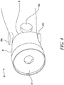
- Figure 4 shows an isometric view of the front part of the gas turbine engine 10.
- the electric machine arrangement can be fitted within the space 31, such that the overall diameter of the engine 10 is reduced.
- the overall power of the electric machines 25a-d is nonetheless relatively high, in part due to the multiplicity of machines enabled by the multiple radial drive shafts 27.
- This multiplicity of electric machines also provides redundancy, such that, in the event of a failure of one electrical machine or radial drive 27, another electric machine can continue to operate. Additional increased power density and improved packaging is provided in view of the architecture of the electric machines 25a-d themselves.
- FIG. 5 shows a first electric machine 25a for the gas turbine engine 10.
- Each machine 25 is in the form of a permanent magnet, axial flux electric machine.
- the machine comprises a machine rotor 32, which is coupled to the radial drive shaft 27 via the reduction gearbox 41a.
- the reduction gearbox is in the form of an epicyclic gearbox, comprising a sun input gear 60 of the gearbox 41a.
- the sun gear 60 meshes with a plurality of planet gears 62, which in turn mesh with a ring gear 64.
- the ring gear is held static, while the planet gears are mounted to a planet carrier 66, which is allowed to rotate and is in turn mounted to the machine rotor 32 to thereby turn the machine rotor 32 at a reduced speed relative to the radial drive shaft 27.
- the rotor 32 of the electric machine 25a comprises a plurality of permanent magnets 33, which are attached to an axial surface of the rotor, and are arranged as shown in figure 5b .
- the permanent magnets face a stator 34 across an airgap 35.
- Each stator comprises a plurality of electric windings (not shown), which can be energised with electrical current to enable the machine to act as a motor, or will be energised by interaction with the rotating magnetic field of the rotor 33 to act as a generator.
- the electric machine 25a can be described as an axial flux electric machine.
- Such machines can have a high power density, and a short axial length, since the power is related to the diameter of the machine, rather than the axial length. Consequently, a high power electric machine can be provided with a radial principal axis 27, whilst maintaining a small overall diameter of the gas turbine engine 10 as a whole.
- FIGs 6a and 6b show an alternative electric machine 125, which can be used in place of the electric machine 25a-d.
- the machine 125 is in the form of a permanent magnet, radial flux electric machine.
- the machine comprises a machine rotor 132, which is directly coupled to the radial drive shaft 27.
- the rotor 132 comprises a plurality of permanent magnets 133, which are attached to an annularly outer surface of the rotor, and are arranged as shown in figure 6b .
- the permanent magnets 133 face a stator 134 across an airgap 135.
- Each stator 135 comprises a plurality of electric windings (not shown), which can be energised with electrical current to enable the machine to act as a motor, or will be energised by interaction with the rotating magnetic field of the rotor 133 to act as a generator.
- magnetic flux from the permanent magnets 133 and stator windings emanate in a radial direction, i.e. normal to an axis of rotation 126 of the electric machine 125. Consequently, the electric machine 125 can be described as a radial flux electric machine.
- Such machines can have a high power density, and a relatively long axial length compared to an equivalent axial flux machine, since the power is related to the axial length of the machine, rather than the diameter.
- Figure 7 shows an alternative gas turbine engine 210 in the form of a geared, high bypass ratio gas turbine engine 210.
- the engine 210 comprises an air intake 212 and a propulsive fan 213 that generates two airflows: a core airflow A and a bypass airflow B.
- the fan 213 differs from the fan 13, in that only a single, low pressure stage is provided. However the fan has a much larger diameter compared to the core 211, and so defines a high bypass ratio.
- the gas turbine engine 210 comprises a core 211 that receives the core airflow A.
- the engine core 211 comprises, in axial flow series, a low pressure compressor 214a, a high pressure compressor 214b, combustion equipment 215, a high-pressure turbine 216, a low pressure turbine 217 and a core exhaust nozzle 218.
- a nacelle 219 surrounds the gas turbine engine 210 and defines a bypass duct 250.
- the bypass airflow B flows through the bypass duct 250, which is bounded by a radially inner wall in the form of a core nacelle 224.
- the fan 213 is attached to and driven by the low pressure turbine 217 via a low pressure shaft 222 and reduction gearbox 240.
- the low pressure turbine also drives the low pressure compressor 214a.
- the high pressure compressor 214b is coupled to the high pressure turbine 216 by a high pressure shaft 223.
- the shafts 222, 223 rotate about a longitudinal axis 219.
- the low pressure turbine 217 drives the low pressure shaft 222, which is coupled to a sun wheel, a sun gear 252 of the gearbox 240.
- the sun gear meshes with a plurality of planet gears 253, which in turn mesh with a statically held ring gear 254.
- the planet gears are mounted to a planet carrier, which is in turn mounted to the fan 213 to thereby turn the fan at a reduced speed compared to the low pressure turbine 217.
- the gas turbine engine 210 additionally comprises an electric machine arrangement, which is configured to produce electrical power, and / or provide motive power to start the engine.
- the electric machine arrangement is similar to the arrangement of the first embodiment, and again comprises at least one, and in this case four electric machines 225a-d, (two of which are shown in figure 7 ), which are arrayed within the core nacelle 224, radially outward of the core gas flow path defined by the compressors 214a, 214b.
- the electric machines 225a-d are again directly coupled to respective radial drive shafts 227, which are in turn driven by the low pressure shaft 222 via a bevel gear arrangement. Again therefore, the electric machines can be provided within the diameter of the gas turbine engine core, without increasing the diameter of the core, thereby providing a lightweight, efficient, dense package, with high levels of redundancy.
- gas turbine engines to which the present disclosure may be applied may have alternative configurations.
- such engines may have an alternative number of compressors and/or turbines and/or an alternative number of interconnecting shafts.
- the gas turbine engine shown in Figure 7 has a split flow nozzle meaning that the flow through the bypass duct has its own nozzle that is separate to and radially outside the core engine nozzle 20.
- this is not limiting, and any aspect of the present disclosure may also apply to engines in which the flow through the bypass duct and the flow through the core are mixed, or combined, before (or upstream of) a single nozzle, which may be referred to as a mixed flow nozzle.
- One or both nozzles may have a fixed or variable area.
- turbofan engine Whilst the described example relates to a turbofan engine, the disclosure may apply, for example, to any type of gas turbine engine, such as an open rotor (in which the fan stage is not surrounded by a nacelle) or turboprop engine, for example.
- gas turbine engine such as an open rotor (in which the fan stage is not surrounded by a nacelle) or turboprop engine, for example.
- the geometry of the gas turbine engine 10, and components thereof, is defined by a conventional axis system, comprising an axial direction (which is aligned with the rotational axis 9), a radial direction (in the bottom-to-top direction in Figure 1 ), and a circumferential direction (perpendicular to the page in the Figure 1 view).
- the axial, radial and circumferential directions are mutually perpendicular.
- hybrid axial / radial flux machines could be used.
- the permanent magnet machines could be replaced with induction machines.
- the machines could be coupled to the high pressure shaft, or could be coupled to the low pressure shaft after the gearbox (i.e. at the output side of the gearbox, where the speed is reduced).
- the machines could be physically located within the bypass nacelle, or radially inward of the bypass and / or core gas flow paths.
- the radial offtake shafts need not extend wholly radially, i.e. they need not be entirely normal to the engine longitudinal direction, provided the offtake shafts extend radially to some extent, i.e. are not parallel to the engine longitudinal direction.
- the offtake shafts may be angled somewhat toward an axially forward or rearward direction, in order to provide for improved packaging.
- the electric machines may be mounted in different locations, and may be coupled to different shafts. For instance, the electric machines may be coupled to the high pressure shaft. In a gas turbine engine comprising three separate spools, the electric machines may be coupled to any of a low pressure, intermediate pressure or high pressure shaft.
- the electric machines could be of different types.
- one or more machine could comprise an induction machine.
- the electric machines could be provided in different locations, such as within the engine core, radially inward of a core gas flow path, or could be located within an engine bypass nacelle.
Landscapes
- Engineering & Computer Science (AREA)
- Chemical & Material Sciences (AREA)
- Combustion & Propulsion (AREA)
- Mechanical Engineering (AREA)
- General Engineering & Computer Science (AREA)
- Connection Of Motors, Electrical Generators, Mechanical Devices, And The Like (AREA)
- Structures Of Non-Positive Displacement Pumps (AREA)
Abstract
Description
- The present disclosure relates to electric machines of gas turbine engines, and gas turbines comprising electrical machines.
- Aircraft gas turbine engines provide both propulsive and electric power for aircraft. Consequently, such engines comprise electric machines such as generators for providing electric power. Further electric machines in the form of motors configured to drive fluid pumps such as oil and fuel pumps may also be provided.
- As electrical power demands increase, and electrical motors are increasingly used to replace hydraulic and pneumatic motors in aircraft, the size of electric machines on aircraft is steadily increasing relative to the size of the gas turbine engines. Consequently, packaging of such machines within the limited space available is becoming increasingly difficult.
- A conventional packaging arrangement for an electric machine for a gas turbine engine is shown in
figure 1 . A gas turbine engine 1 comprises a mainengine compressor shaft 2, which rotates when the engine 1 is in operation. Themain engine shaft 2 is coupled to anofftake shaft 3 via a first set of bevel gears 4. Theofftake shaft 3 is in turn coupled to anangle drive shaft 5 through a second set of bevel gears 6. An electric machine 7 is coupled to theangle drive shaft 5. Such an arrangement is heavy, complex, and inefficient, in view of the gearing. - Alternative arrangements have also been proposed, including so-called "embedded generators" such as that shown in
figure 2 . In an embedded arrangement, anelectric machine 7A is installed within an annular space radially inward of acompressor 8A of agas turbine engine 1A, and is driven directly by amain engine shaft 2A. Such an arrangement provides for efficient packaging, but provides difficulty for access for maintenance, and requires that the electric machine be operated in a hot environment. - The present invention seeks to provide an improved packaging arrangement.
- According to a first aspect there is provided an aircraft gas turbine engine comprising:
- a main engine shaft arranged to couple a turbine and a compressor, the main engine shaft defining an axial direction;
- at least one radially extending offtake shaft coupled to the main engine shaft; and a radially extending electric machine coupled to the radially extending offtake shaft.
- The inventors have found that, by re-orienting the electric machine to a radial orientation, and coupling the electric machine to the offtake shaft, an arrangement can be provided which is at least one of lighter, more compact, and more efficient.
- The electric machine may be directly coupled to the radially extending offtake shaft. advantageously, such an arrangement is compact and efficient, in view of the reduced gearing.
- Alternatively, the electric machine may be coupled to the radially extending offtake shaft by a reduction gearbox. Advantageously, a high speed offtake shaft can be used, which can transfer high power at relatively low torque. The other hand, the electric machine can rotate relatively slowly, which can allow for a large radius electric machine to be used, which may have a high power density.
- The electric machine may comprise an electric motor configured to provide motive power to start the gas turbine engine in a starting mode, and may comprise a generator configured to generate electrical power when in a running mode.
- The electric machine may comprise an axial flux electric machine in which a stator of the electric machine is axially offset relative to a rotor of the electric machine. Consequently, the electric machine can have a smaller axial depth for a given power, which greatly increases packaging efficiency of the arrangement. Alternatively, the electric machine may comprise a radial flux electric machine, in which a stator of the electric machine is radially inward or radially outward of a rotor of the electric machine.
- The gas turbine engine may comprise a plurality of radially extending offtake shafts circumferentially arrayed around the main engine shaft. Each radially extending offtake shaft may be coupled to a respective radially extending electric machine. Consequently, instead of a single electric machine, several are provided, distributed about the circumference of the engine. This provides several advantages, including further increased packaging, as well as increased redundancy, since an electric machine can continue to operate in the event of a failure of either an offtake drive shaft or an electric machine.
- The gas turbine engine may comprise a low pressure compressor or a fan coupled to a low pressure turbine by a low pressure shaft, and the offtake shaft may be coupled to the low pressure shaft. The gas turbine engine may comprise a high pressure compressor coupled to a high pressure turbine by a high pressure shaft, and the offtake shaft may be coupled to the high pressure shaft. The low and high pressure shafts may be coaxial, and the low pressure shaft may be provided radially inward of the high pressure shaft along at least part of its length.
- The low pressure compressor may be located axially forwardly of the high pressure compressor.
- The gas turbine engine may comprise a fan coupled to main engine shaft.
- One or more offtake shaft may be coupled to the main engine shaft at an axial space between the high and low pressure compressors. Typically, at least in some engine designs, the engine narrows at this point before widening again, meaning that the generators can be provided within this region, such that the engine as a whole is approximately cylindrical. Consequently, greatly improved packaging is provided.
- The electric machine may comprise a permanent magnet electric machine. Permanent magnet machines have a high power density, and so enable still further reductions in weight, and increased packaging efficiency.
- Arrangements of the present disclosure may be particularly, although not exclusively, beneficial for fans that are driven via a gearbox. Accordingly, the gas turbine engine may comprise a fan speed reduction gearbox that receives an input from one or more main engine shaft and outputs drive to the fan so as to drive the fan at a lower rotational speed than the main engine shaft. The input to the gearbox may be directly from the main engine shaft, or indirectly from the main engine shaft, for example via a spur shaft and/or gear. The main engine shaft may rigidly connect the turbine and the compressor, such that the turbine and compressor rotate at the same speed (with the fan rotating at a lower speed).
- The gas turbine engine as described and/or claimed herein may have any suitable general architecture. For example, the gas turbine engine may have any desired number of shafts that connect turbines and compressors, for example one, two or three shafts.
- The gearbox may be arranged to be driven by the core shaft that is configured to rotate (for example in use) at the lowest rotational speed (for example the first core shaft in the example above). For example, the gearbox may be arranged to be driven only by the core shaft that is configured to rotate (for example in use) at the lowest rotational speed (for example only be the first core shaft, and not the second core shaft, in the example above). Alternatively, the gearbox may be arranged to be driven by any one or more shafts, for example the first and/or second shafts in the example above.
- The skilled person will appreciate that except where mutually exclusive, a feature or parameter described in relation to any one of the above aspects may be applied to any other aspect. Furthermore, except where mutually exclusive, any feature or parameter described herein may be applied to any aspect and/or combined with any other feature or parameter described herein.
- Embodiments will now be described by way of example only, with reference to the Figures, in which:
-
Figure 1 is a sectional side view of a first prior gas turbine engine; -
Figure 2 is a sectional side view of a second prior gas turbine engine; -
Figure 3 is a sectional side view of a first gas turbine engine in accordance with the present disclosure; -
Figure 4 is an isometric view from the front and one side of the gas turbine engine offigure 3 ; -
Figure 5a is a sectional side view of an electric machine of the gas turbine engine offigure 3 ; -
Figure 5b is a sectional side view of the electric machine offigure 4a through the line A-A; -
Figure 6 is a sectional side view of an alternative electric machine for the gas turbine engine offigure 3 ; and -
Figure 7 is a sectional side view of a second gas turbine engine in accordance with the present disclosure. -
Figure 3 illustrates agas turbine engine 10 having a principalrotational axis 9. Theengine 10 comprises anair intake 12 and apropulsive fan 13 that generates two airflows: a core airflow A and a bypass airflow B. Thegas turbine engine 10 comprises a core 11 that receives the core airflow A. Theengine core 11 comprises, in axial flow series, acompressor 14,combustion equipment 15, a high-pressure turbine 16, alow pressure turbine 17 and acore exhaust nozzle 18. Anacelle 19 surrounds thegas turbine engine 10 and defines abypass duct 20 and abypass exhaust nozzle 21. The bypass airflow B flows through thebypass duct 50, which is bounded by a radially inner wall in the form of acore nacelle 24. Thefan 13 is attached to and driven by thelow pressure turbine 17 via alow pressure shaft 22. Thecompressor 14 is coupled to thehigh pressure turbine 16 by ahigh pressure shaft 13. The high andlow pressure shafts main engine turbines engine 10. - In use, the core airflow A is accelerated and compressed by the
compressor 14 and directed into thecombustion equipment 15 where it is mixed with fuel and the mixture is combusted. The resultant hot combustion products then expand through, and thereby drive, the high pressure andlow pressure turbines nozzle 18 to provide some propulsive thrust. Thehigh pressure turbine 16 drives thecompressor 14 by ahigh pressure shaft 13. Thefan 13 is in the form of a high pressure, low bypass ratio, multi-stage fan. In view of the high pressure ratio of thefan 13, thefan 13 can be regarded as a further compressor. - The gas turbine engine comprises an electric machine arrangement, which is configured to produce electrical power, and / or provide motive power to start the engine. The electric machine arrangement comprises at least one, and in this case four
electric machines 25a-d, (two of which are shown infigure 3 , a third is shown infigure 4 , and the fourth 25d is not shown, but is on the opposite side to the thirdelectric machine 25c), which are arrayed around thefan nacelle 19. - Each electric machine is provided at a location generally between the
fan 13 andcompressor 14. In this location, thenacelle 19 outer line contracts inwardly, before expanding outwardly axially downstream. Consequently, aspace 31 is provided, in which an electric machine can be provided. If an electric machine can be provided wholly within this space, the overall width of theengine 10 can be reduced to be substantially the same as the bypass duct, which will then represent the largest part. Consequently, an aircraft having such a small engine installation can be made to be more aerodynamic, and therefore faster, more fuel efficient, or longer ranged. However, this space is relatively small, and so it is highly challenging to provide an installation arrangement in which electric machines are wholly or at least largely confined to this space. - Each electric machine defines an
axis 26. As can be seen fromfigure 3 , the axis of eachelectric machine 25a-d is generally radial relative to the enginelongitudinal axis 9, i.e. theaxis 26 of eachelectric machine longitudinal axis 9. This is enabled by mounting the respective electric machines without an intermediate bevel gearbox to an offtake shaft in the form of aradial drive shaft 27, i.e. without changing the rotational axis to be parallel with themain engine shafts - Each
radial drive shaft 27 is coupled to thelow pressure shaft 22 via abevel gear arrangement 28. Thebevel gear arrangement 28 is located in anaxial space 51 provided between the low andhigh pressure compressors first bevel gear 29, which rotates with thelow pressure shaft 22, and meshes with second and third 30, 31 bevel gears, which rotate about the axis of theradial drive shaft 27. Fourth and fifth bevel gears (not shown) are provided for the third and fourth electric machines. - Consequently, the
radial drive shaft 27 is driven by thelow pressure shaft 22 via thebevel gear arrangement 28 where theelectric machines low pressure shaft 22 is driven by theelectric machines electric machines - The
electric machines radial drive shaft 27, and in this embodiment are instead coupled by anintermediate reduction gearbox 41a, 41b, which is provided at a radially outward end of each radial drive shaft 27adjacent a respectiveelectric machine -
Figure 4 shows an isometric view of the front part of thegas turbine engine 10. As can be seen, in view of the radial axis of theelectric machines space 31, such that the overall diameter of theengine 10 is reduced. The overall power of theelectric machines 25a-d is nonetheless relatively high, in part due to the multiplicity of machines enabled by the multipleradial drive shafts 27. This multiplicity of electric machines also provides redundancy, such that, in the event of a failure of one electrical machine orradial drive 27, another electric machine can continue to operate. Additional increased power density and improved packaging is provided in view of the architecture of theelectric machines 25a-d themselves. -
Figure 5 shows a firstelectric machine 25a for thegas turbine engine 10. Each machine 25 is in the form of a permanent magnet, axial flux electric machine. The machine comprises amachine rotor 32, which is coupled to theradial drive shaft 27 via thereduction gearbox 41a. As can be seen, the reduction gearbox is in the form of an epicyclic gearbox, comprising asun input gear 60 of thegearbox 41a. Thesun gear 60 meshes with a plurality of planet gears 62, which in turn mesh with aring gear 64. The ring gear is held static, while the planet gears are mounted to aplanet carrier 66, which is allowed to rotate and is in turn mounted to themachine rotor 32 to thereby turn themachine rotor 32 at a reduced speed relative to theradial drive shaft 27. - The
rotor 32 of theelectric machine 25a comprises a plurality ofpermanent magnets 33, which are attached to an axial surface of the rotor, and are arranged as shown infigure 5b . The permanent magnets face astator 34 across anairgap 35. Each stator comprises a plurality of electric windings (not shown), which can be energised with electrical current to enable the machine to act as a motor, or will be energised by interaction with the rotating magnetic field of therotor 33 to act as a generator. - As can be seen, magnetic flux from the
permanent magnets 33 and stator windings emanate in an axial direction, i.e. parallel to the axis ofrotation 26 of theelectric machine 25a. Consequently, theelectric machine 25a can be described as an axial flux electric machine. Such machines can have a high power density, and a short axial length, since the power is related to the diameter of the machine, rather than the axial length. Consequently, a high power electric machine can be provided with a radialprincipal axis 27, whilst maintaining a small overall diameter of thegas turbine engine 10 as a whole. It has been found that incorporating a reduction gearbox between the radial drive shaft and themachine rotor 32 is particularly advantageous for an axial flux machine, since axial flux machines tend to have relatively large diameter rotors, and so this arrangement results in lower rotor tip speeds, and so lower stresses on therotor 32. -
Figures 6a and 6b show an alternativeelectric machine 125, which can be used in place of theelectric machine 25a-d. Themachine 125 is in the form of a permanent magnet, radial flux electric machine. The machine comprises amachine rotor 132, which is directly coupled to theradial drive shaft 27. Therotor 132 comprises a plurality ofpermanent magnets 133, which are attached to an annularly outer surface of the rotor, and are arranged as shown infigure 6b . Thepermanent magnets 133 face astator 134 across anairgap 135. Eachstator 135 comprises a plurality of electric windings (not shown), which can be energised with electrical current to enable the machine to act as a motor, or will be energised by interaction with the rotating magnetic field of therotor 133 to act as a generator. - As can be seen, magnetic flux from the
permanent magnets 133 and stator windings emanate in a radial direction, i.e. normal to an axis ofrotation 126 of theelectric machine 125. Consequently, theelectric machine 125 can be described as a radial flux electric machine. Such machines can have a high power density, and a relatively long axial length compared to an equivalent axial flux machine, since the power is related to the axial length of the machine, rather than the diameter. -
Figure 7 shows an alternativegas turbine engine 210 in the form of a geared, high bypass ratiogas turbine engine 210. Theengine 210 comprises anair intake 212 and apropulsive fan 213 that generates two airflows: a core airflow A and a bypass airflow B. thefan 213 differs from thefan 13, in that only a single, low pressure stage is provided. However the fan has a much larger diameter compared to thecore 211, and so defines a high bypass ratio. Thegas turbine engine 210 comprises a core 211 that receives the core airflow A. Theengine core 211 comprises, in axial flow series, alow pressure compressor 214a, a high pressure compressor 214b,combustion equipment 215, a high-pressure turbine 216, alow pressure turbine 217 and acore exhaust nozzle 218. Anacelle 219 surrounds thegas turbine engine 210 and defines abypass duct 250. The bypass airflow B flows through thebypass duct 250, which is bounded by a radially inner wall in the form of acore nacelle 224. Thefan 213 is attached to and driven by thelow pressure turbine 217 via alow pressure shaft 222 andreduction gearbox 240. The low pressure turbine also drives thelow pressure compressor 214a. The high pressure compressor 214b is coupled to thehigh pressure turbine 216 by ahigh pressure shaft 223. Theshafts longitudinal axis 219. - The
low pressure turbine 217 drives thelow pressure shaft 222, which is coupled to a sun wheel, asun gear 252 of thegearbox 240. The sun gear meshes with a plurality of planet gears 253, which in turn mesh with a statically heldring gear 254. The planet gears are mounted to a planet carrier, which is in turn mounted to thefan 213 to thereby turn the fan at a reduced speed compared to thelow pressure turbine 217. - The
gas turbine engine 210 additionally comprises an electric machine arrangement, which is configured to produce electrical power, and / or provide motive power to start the engine. The electric machine arrangement is similar to the arrangement of the first embodiment, and again comprises at least one, and in this case fourelectric machines 225a-d, (two of which are shown infigure 7 ), which are arrayed within thecore nacelle 224, radially outward of the core gas flow path defined by thecompressors 214a, 214b. Theelectric machines 225a-d are again directly coupled to respectiveradial drive shafts 227, which are in turn driven by thelow pressure shaft 222 via a bevel gear arrangement. Again therefore, the electric machines can be provided within the diameter of the gas turbine engine core, without increasing the diameter of the core, thereby providing a lightweight, efficient, dense package, with high levels of redundancy. - Other gas turbine engines to which the present disclosure may be applied may have alternative configurations. For example, such engines may have an alternative number of compressors and/or turbines and/or an alternative number of interconnecting shafts. By way of further example, the gas turbine engine shown in
Figure 7 has a split flow nozzle meaning that the flow through the bypass duct has its own nozzle that is separate to and radially outside thecore engine nozzle 20. However, this is not limiting, and any aspect of the present disclosure may also apply to engines in which the flow through the bypass duct and the flow through the core are mixed, or combined, before (or upstream of) a single nozzle, which may be referred to as a mixed flow nozzle. One or both nozzles (whether mixed or split flow) may have a fixed or variable area. - Whilst the described example relates to a turbofan engine, the disclosure may apply, for example, to any type of gas turbine engine, such as an open rotor (in which the fan stage is not surrounded by a nacelle) or turboprop engine, for example.
- The geometry of the
gas turbine engine 10, and components thereof, is defined by a conventional axis system, comprising an axial direction (which is aligned with the rotational axis 9), a radial direction (in the bottom-to-top direction inFigure 1 ), and a circumferential direction (perpendicular to the page in theFigure 1 view). The axial, radial and circumferential directions are mutually perpendicular. - Different types of electric machines could be used. For example, hybrid axial / radial flux machines could be used. The permanent magnet machines could be replaced with induction machines. The machines could be coupled to the high pressure shaft, or could be coupled to the low pressure shaft after the gearbox (i.e. at the output side of the gearbox, where the speed is reduced). The machines could be physically located within the bypass nacelle, or radially inward of the bypass and / or core gas flow paths.
- It will be understood that the invention is not limited to the embodiments above-described and various modifications and improvements can be made without departing from the concepts described herein. Except where mutually exclusive, any of the features may be employed separately or in combination with any other features and the disclosure extends to and includes all combinations and subcombinations of one or more features described herein.
- For example, the radial offtake shafts need not extend wholly radially, i.e. they need not be entirely normal to the engine longitudinal direction, provided the offtake shafts extend radially to some extent, i.e. are not parallel to the engine longitudinal direction. For instance, the offtake shafts may be angled somewhat toward an axially forward or rearward direction, in order to provide for improved packaging.
- The electric machines may be mounted in different locations, and may be coupled to different shafts. For instance, the electric machines may be coupled to the high pressure shaft. In a gas turbine engine comprising three separate spools, the electric machines may be coupled to any of a low pressure, intermediate pressure or high pressure shaft.
- The electric machines could be of different types. For instance, one or more machine could comprise an induction machine. The electric machines could be provided in different locations, such as within the engine core, radially inward of a core gas flow path, or could be located within an engine bypass nacelle.
Claims (13)
- An aircraft gas turbine engine (10) comprising:a main engine shaft (22) arranged to couple a turbine (17) and a compressor (13), the main engine shaft (22) defining an axial direction (9);at least one radially extending offtake shaft (27) coupled to the main engine shaft (22); anda radially extending electric machine (25a, 25b) coupled to the radially extending offtake shaft (22).
- A gas turbine engine according to claim 1, wherein the electric machine (225a, 225b) is directly coupled to the radially extending offtake shaft (227).
- A gas turbine engine according to claim 1, wherein the electric machine (25a, 25b) is coupled to the radially extending offtake shaft by a reduction gearbox (41a, 41b).
- A gas turbine engine according to any of the preceding claims, wherein the electric machine comprises at least one of an electric motor (25a, 25b) configured to provide motive power to start the gas turbine engine (10) in a starting mode, and a generator (25a, 25b) configured to generate electrical power when in a running mode.
- A gas turbine engine according to any of the preceding claims, wherein the electric machine (25a, 25b) comprises an axial flux electric machine in which a stator (34) of the electric machine (25a, 25b) is axially offset relative to a rotor (32) of the electric machine (25a, 25b).
- A gas turbine engine according to any of claims 1 to 4, wherein the electric machine (125) comprises a radial flux electric machine, in which a stator (134) of the electric machine (125) is radially inward or radially outward of a rotor (132) of the electric machine (125).
- A gas turbine engine according to any of the preceding claims, wherein the gas turbine engine (10) comprises a plurality of radially extending offtake shafts (27) circumferentially arrayed around the main engine shaft (22).
- A gas turbine engine according to claim 7, wherein each radially extending offtake shaft (27) is directly coupled to a respective radially extending electric machine (25a, 25b).
- A gas turbine according to any of the preceding claims, wherein the gas turbine engine comprise a low pressure compressor (13) or a fan (12) coupled to a low pressure turbine (17) by a low pressure shaft (22), and may comprise a high pressure compressor (14) coupled to a high pressure turbine (16) by a high pressure shaft (23).
- A gas turbine engine according to claim 9, wherein one or more offtake shaft (27) is coupled to one of the low pressure shaft (22) and the high pressure shaft (23).
- A gas turbine engine according to claim 10, wherein one or more offtake shaft (27) is coupled to the main engine shaft (22) at an axial space (51) between the high and low pressure compressors
- A gas turbine engine according to any of the preceding claims, wherein the electric machine comprises a permanent magnet electric machine (25a, 25b).
- A gas turbine engine according to any of the preceding claims, wherein the gas turbine engine (110) comprises a fan speed reduction gearbox (240) that receives an input from one or more main engine shaft (223) and outputs drive to a fan (213) so as to drive the fan (213) at a lower rotational speed than the main engine shaft (223).
Applications Claiming Priority (1)
| Application Number | Priority Date | Filing Date | Title |
|---|---|---|---|
| GBGB1910011.4A GB201910011D0 (en) | 2019-07-12 | 2019-07-12 | Gas turbine engine electrical generator |
Publications (1)
| Publication Number | Publication Date |
|---|---|
| EP3763931A1 true EP3763931A1 (en) | 2021-01-13 |
Family
ID=67700191
Family Applications (1)
| Application Number | Title | Priority Date | Filing Date |
|---|---|---|---|
| EP20180140.4A Withdrawn EP3763931A1 (en) | 2019-07-12 | 2020-06-16 | Gas turbine engine electrical generator |
Country Status (4)
| Country | Link |
|---|---|
| US (1) | US11230942B2 (en) |
| EP (1) | EP3763931A1 (en) |
| CN (1) | CN112211732A (en) |
| GB (1) | GB201910011D0 (en) |
Cited By (4)
| Publication number | Priority date | Publication date | Assignee | Title |
|---|---|---|---|---|
| GB2605673A (en) * | 2021-09-08 | 2022-10-12 | Rolls Royce Plc | An improved gas turbine engine |
| US11879413B2 (en) | 2021-09-08 | 2024-01-23 | Rolls-Royce Plc | Gas turbine engine |
| US11976611B2 (en) | 2021-09-08 | 2024-05-07 | Rolls-Royce Plc | Gas turbine engine |
| US11988151B1 (en) | 2023-03-07 | 2024-05-21 | Rolls-Royce North American Technologies, Inc. | Embedded electric machine of gas turbine engine |
Families Citing this family (18)
| Publication number | Priority date | Publication date | Assignee | Title |
|---|---|---|---|---|
| US12037913B2 (en) * | 2020-11-02 | 2024-07-16 | Ge Avio S.R.L. | Electric machine assembly for a turbine engine |
| US12060833B2 (en) | 2021-08-10 | 2024-08-13 | Rolls-Royce North American Technologies, Inc. | Gas turbine engine system with motor-generator |
| GB2613247B (en) | 2021-10-15 | 2024-04-03 | Raytheon Tech Corp | Electric machine within a turbine engine |
| GB2613076B (en) | 2021-10-15 | 2024-06-05 | Rtx Corp | Electric machine within a turbine engine |
| GB2613246B (en) | 2021-10-15 | 2024-05-29 | Rtx Corp | Lubrication system for turbine engine electric machine |
| US11994038B2 (en) | 2021-10-15 | 2024-05-28 | Rtx Corporation | Turbine engine module with electric machine |
| EP4166774B1 (en) | 2021-10-15 | 2025-07-16 | RTX Corporation | Double splined coupling for a turbine engine |
| EP4166762A3 (en) | 2021-10-15 | 2023-08-09 | Raytheon Technologies Corporation | Radial outward bearing support for a rotating structure of a turbine engine |
| US12140089B2 (en) | 2021-12-27 | 2024-11-12 | Rolls-Royce North American Technologies, Inc. | Gas turbine engine system with generator |
| US12320295B2 (en) | 2021-12-27 | 2025-06-03 | Rolls-Royce North American Technologies, Inc. | Gas turbine engine system with generator |
| US12510026B1 (en) | 2022-02-04 | 2025-12-30 | Rtx Corporation | Lubrication system for aircraft propulsion system with electric machine |
| US12240615B2 (en) * | 2022-12-12 | 2025-03-04 | General Electric Company | Electric propulsor with electric machine in thermal communication with a heat exchanger |
| US12583609B2 (en) | 2022-12-23 | 2026-03-24 | Pratt & Whitney Canada Corp. | Exhaust duct for hybrid aircraft powerplant |
| US12215630B2 (en) | 2022-12-23 | 2025-02-04 | Pratt & Whitney Canada Corp. | Flex coupler for hybrid gas turbine engine powerplant |
| US20240328363A1 (en) * | 2023-03-31 | 2024-10-03 | Pratt & Whitney Canada Corp. | Power coupling between engine rotating assembly and external device |
| FR3147557B1 (en) * | 2023-04-04 | 2025-02-28 | Safran Aircraft Engines | Propulsion assembly for the rear of an aircraft fuselage |
| US20250132637A1 (en) * | 2023-10-19 | 2025-04-24 | Richard Christopher Uskert | Axial brushless motor generator |
| US12546259B2 (en) | 2024-03-08 | 2026-02-10 | General Electric Company | Systems and methods for integrating use of starter on the low pressure spool of a turbine engine |
Citations (2)
| Publication number | Priority date | Publication date | Assignee | Title |
|---|---|---|---|---|
| GB2443743A (en) * | 2006-11-13 | 2008-05-14 | Hamilton Sundstrand Corp | Turbofan emergency generator |
| EP1939429A2 (en) * | 2006-12-21 | 2008-07-02 | General Electric Company | Power take-off system and gas turbine engine assembly including same |
Family Cites Families (36)
| Publication number | Priority date | Publication date | Assignee | Title |
|---|---|---|---|---|
| DE3218927A1 (en) | 1982-05-19 | 1983-11-24 | Klöckner-Humboldt-Deutz AG, 5000 Köln | GAS TURBINE ENGINE FOR AN AIRCRAFT |
| RU2168024C2 (en) | 1998-12-23 | 2001-05-27 | Открытое акционерное общество "Рыбинские моторы" | Gas-turbine engine |
| EP1421666B1 (en) | 2001-08-30 | 2006-10-11 | Siemens Aktiengesellschaft | Shock-proof electric marine engine, e.g. engine or generator |
| US7550218B2 (en) | 2001-10-11 | 2009-06-23 | Airbus Deutschland Gmbh | Apparatus for producing water onboard of a craft driven by a power plant |
| US7692347B2 (en) | 2004-10-12 | 2010-04-06 | Nissan Motor Co., Ltd. | Vibration damping for a rotating shaft |
| FR2877990B1 (en) | 2004-11-16 | 2007-02-09 | Snecma Moteurs Sa | TURBOMACHINE WITH DEVICE FOR THE AUTOMATIC DETECTION OF FERROMAGNETIC PARTICLES IN AN OIL ENCLOSURE |
| US20060137355A1 (en) | 2004-12-27 | 2006-06-29 | Pratt & Whitney Canada Corp. | Fan driven emergency generator |
| US7966830B2 (en) | 2006-06-29 | 2011-06-28 | The Boeing Company | Fuel cell/combustor systems and methods for aircraft and other applications |
| US7648278B2 (en) | 2007-01-05 | 2010-01-19 | Honeywell International Inc. | High speed aerospace generator resilient mount, combined centering spring and squeeze film damper |
| DE102008031185A1 (en) * | 2008-07-03 | 2010-01-07 | Rolls-Royce Deutschland Ltd & Co Kg | Turbofan engine with at least one device for driving at least one generator |
| US8097972B2 (en) | 2009-06-29 | 2012-01-17 | Pratt & Whitney Canada Corp. | Gas turbine with magnetic shaft forming part of a generator/motor assembly |
| US8966911B2 (en) | 2009-12-29 | 2015-03-03 | Rolls-Royce North American Technologies, Inc. | Turbofan engine with HP and LP power off-takes |
| FR2955085B1 (en) * | 2010-01-08 | 2011-12-23 | Snecma | SYSTEM FOR CONTRAROTATIVE PROPELLERS FOR AIRCRAFT TURBOMACHINE |
| DE102010049885B4 (en) | 2010-11-01 | 2015-06-25 | Rolls-Royce Deutschland Ltd & Co Kg | Jet engine |
| DE102011112255A1 (en) * | 2011-09-02 | 2013-03-07 | Rolls-Royce Deutschland Ltd & Co Kg | Auxiliary gear device for an engine |
| DE102011112250A1 (en) * | 2011-09-02 | 2013-03-07 | Rolls-Royce Deutschland Ltd & Co Kg | Auxiliary gear device for an engine |
| JP5568596B2 (en) | 2012-05-30 | 2014-08-06 | 川崎重工業株式会社 | Aircraft engine gearbox integrated power generator |
| WO2014150377A1 (en) | 2013-03-15 | 2014-09-25 | Embry-Riddle Aeronautical University, Inc. | Electrically coupled counter-rotation for gas turbine compressors |
| US20140306460A1 (en) | 2013-04-16 | 2014-10-16 | Icr Turbine Engine Corporation | High speed direct drive generator for a gas turbine engine |
| DE102013209388B4 (en) | 2013-05-22 | 2021-07-22 | Robert Bosch Gmbh | Hybrid propulsion for power-powered aircraft, power-powered aircraft with hybrid drive and associated operating method |
| EP2878795B8 (en) | 2013-11-27 | 2016-10-12 | Airbus Operations GmbH | Engine for propelling an aircraft and aircraft having at least one engine and at least one hydrogen tank |
| GB201520131D0 (en) * | 2015-11-16 | 2015-12-30 | Rolls Royce Plc | Variable gear ratio electrical machine |
| US10662878B2 (en) | 2016-02-03 | 2020-05-26 | Honeywell Internatioanl Inc. | Compact accessory systems for a gas turbine engine |
| GB2547674A (en) * | 2016-02-25 | 2017-08-30 | Rolls Royce Plc | Gas turbine engine |
| GB2550397B (en) | 2016-05-19 | 2018-11-21 | Derwent Aviation Consulting Ltd | A turbo machine comprising a compressor system |
| CA3024506C (en) | 2016-05-25 | 2020-05-26 | General Electric Company | Turbine bearing support |
| US10487839B2 (en) | 2016-08-22 | 2019-11-26 | General Electric Company | Embedded electric machine |
| US10826344B2 (en) | 2016-11-17 | 2020-11-03 | General Electric Company | High speed electric machine with embedded rotor magnets |
| JP6856403B2 (en) | 2017-02-24 | 2021-04-07 | 本田技研工業株式会社 | Squeeze film damper bearing device |
| CA3000360C (en) | 2017-04-14 | 2020-05-26 | General Electric Company | Support assembly having variable stiffness member |
| GB201712993D0 (en) * | 2017-08-14 | 2017-09-27 | Rolls Royce Plc | Gas turbine engine |
| US10710734B2 (en) | 2017-08-29 | 2020-07-14 | The Boeing Company | Hybrid aircraft propulsors having electrically-driven augmentor fans |
| US11067003B2 (en) | 2017-09-29 | 2021-07-20 | General Electric Company | Fluid cooling structure for an electric machine of a gas turbine engine |
| GB201800673D0 (en) | 2018-01-16 | 2018-02-28 | Rolls Royce Plc | An accesssory gearbox assembly and a gas turbine engine comprising an accessory gearbox assembly |
| US10801410B2 (en) | 2018-04-12 | 2020-10-13 | Raytheon Technologies Corporation | Thermal management of tail cone mounted generator |
| US10495144B1 (en) | 2018-05-25 | 2019-12-03 | Borgwarner Inc. | Single-row ball bearing with integrated squeeze-film damper |
-
2019
- 2019-07-12 GB GBGB1910011.4A patent/GB201910011D0/en not_active Ceased
-
2020
- 2020-06-16 EP EP20180140.4A patent/EP3763931A1/en not_active Withdrawn
- 2020-06-29 US US16/915,032 patent/US11230942B2/en active Active
- 2020-06-29 CN CN202010601456.9A patent/CN112211732A/en active Pending
Patent Citations (2)
| Publication number | Priority date | Publication date | Assignee | Title |
|---|---|---|---|---|
| GB2443743A (en) * | 2006-11-13 | 2008-05-14 | Hamilton Sundstrand Corp | Turbofan emergency generator |
| EP1939429A2 (en) * | 2006-12-21 | 2008-07-02 | General Electric Company | Power take-off system and gas turbine engine assembly including same |
Cited By (7)
| Publication number | Priority date | Publication date | Assignee | Title |
|---|---|---|---|---|
| GB2605673A (en) * | 2021-09-08 | 2022-10-12 | Rolls Royce Plc | An improved gas turbine engine |
| GB2610658A (en) * | 2021-09-08 | 2023-03-15 | Rolls Royce Plc | An improved gas turbine engine |
| GB2605673B (en) * | 2021-09-08 | 2023-11-15 | Rolls Royce Plc | An improved gas turbine engine |
| US11879413B2 (en) | 2021-09-08 | 2024-01-23 | Rolls-Royce Plc | Gas turbine engine |
| US11976611B2 (en) | 2021-09-08 | 2024-05-07 | Rolls-Royce Plc | Gas turbine engine |
| GB2610658B (en) * | 2021-09-08 | 2025-05-07 | Rolls Royce Plc | An improved gas turbine engine |
| US11988151B1 (en) | 2023-03-07 | 2024-05-21 | Rolls-Royce North American Technologies, Inc. | Embedded electric machine of gas turbine engine |
Also Published As
| Publication number | Publication date |
|---|---|
| GB201910011D0 (en) | 2019-08-28 |
| CN112211732A (en) | 2021-01-12 |
| US11230942B2 (en) | 2022-01-25 |
| US20210010384A1 (en) | 2021-01-14 |
Similar Documents
| Publication | Publication Date | Title |
|---|---|---|
| US11230942B2 (en) | Gas turbine engine electrical generator | |
| US10393028B1 (en) | Geared compressor for gas turbine engine | |
| EP3763929B1 (en) | Gas turbine engine electrical generator | |
| EP3763928B1 (en) | Gas turbine engine electrical generator | |
| US11313440B2 (en) | Epicyclic gearbox | |
| EP3023601B1 (en) | Tail cone generator with integral speed increasing gearbox | |
| US8198744B2 (en) | Integrated boost cavity ring generator for turbofan and turboshaft engines | |
| EP2992198B1 (en) | Two shaft turbo machine | |
| EP3904657B1 (en) | Hybrid amplification of high spool motoring via low spool power extraction and motoring of a differential geared generator | |
| US11821323B2 (en) | Power generation system | |
| EP3511557B1 (en) | An epicyclic geartrain | |
| EP3020942B1 (en) | Gas turbine electrical machine arrangement |
Legal Events
| Date | Code | Title | Description |
|---|---|---|---|
| PUAI | Public reference made under article 153(3) epc to a published international application that has entered the european phase |
Free format text: ORIGINAL CODE: 0009012 |
|
| STAA | Information on the status of an ep patent application or granted ep patent |
Free format text: STATUS: THE APPLICATION HAS BEEN PUBLISHED |
|
| AK | Designated contracting states |
Kind code of ref document: A1 Designated state(s): AL AT BE BG CH CY CZ DE DK EE ES FI FR GB GR HR HU IE IS IT LI LT LU LV MC MK MT NL NO PL PT RO RS SE SI SK SM TR |
|
| AX | Request for extension of the european patent |
Extension state: BA ME |
|
| STAA | Information on the status of an ep patent application or granted ep patent |
Free format text: STATUS: REQUEST FOR EXAMINATION WAS MADE |
|
| 17P | Request for examination filed |
Effective date: 20210701 |
|
| RBV | Designated contracting states (corrected) |
Designated state(s): AL AT BE BG CH CY CZ DE DK EE ES FI FR GB GR HR HU IE IS IT LI LT LU LV MC MK MT NL NO PL PT RO RS SE SI SK SM TR |
|
| STAA | Information on the status of an ep patent application or granted ep patent |
Free format text: STATUS: EXAMINATION IS IN PROGRESS |
|
| 17Q | First examination report despatched |
Effective date: 20220920 |
|
| STAA | Information on the status of an ep patent application or granted ep patent |
Free format text: STATUS: THE APPLICATION IS DEEMED TO BE WITHDRAWN |
|
| 18D | Application deemed to be withdrawn |
Effective date: 20230131 |