EP3763590B1 - Real-time acceleration sensor correction device for measuring vehicle movement, and acceleration sensor correction method using same - Google Patents
Real-time acceleration sensor correction device for measuring vehicle movement, and acceleration sensor correction method using same Download PDFInfo
- Publication number
- EP3763590B1 EP3763590B1 EP18909077.2A EP18909077A EP3763590B1 EP 3763590 B1 EP3763590 B1 EP 3763590B1 EP 18909077 A EP18909077 A EP 18909077A EP 3763590 B1 EP3763590 B1 EP 3763590B1
- Authority
- EP
- European Patent Office
- Prior art keywords
- vector
- acceleration
- acceleration sensor
- value
- vehicle
- Prior art date
- Legal status (The legal status is an assumption and is not a legal conclusion. Google has not performed a legal analysis and makes no representation as to the accuracy of the status listed.)
- Active
Links
Images


Classifications
-
- G—PHYSICS
- G08—SIGNALLING
- G08B—SIGNALLING SYSTEMS, e.g. PERSONAL CALLING SYSTEMS; ORDER TELEGRAPHS; ALARM SYSTEMS
- G08B25/00—Alarm systems in which the location of the alarm condition is signalled to a central station, e.g. fire or police telegraphic systems
- G08B25/01—Alarm systems in which the location of the alarm condition is signalled to a central station, e.g. fire or police telegraphic systems characterised by the transmission medium
- G08B25/10—Alarm systems in which the location of the alarm condition is signalled to a central station, e.g. fire or police telegraphic systems characterised by the transmission medium using wireless transmission systems
-
- G—PHYSICS
- G01—MEASURING; TESTING
- G01C—MEASURING DISTANCES, LEVELS OR BEARINGS; SURVEYING; NAVIGATION; GYROSCOPIC INSTRUMENTS; PHOTOGRAMMETRY OR VIDEOGRAMMETRY
- G01C25/00—Manufacturing, calibrating, cleaning, or repairing instruments or devices referred to in the other groups of this subclass
- G01C25/005—Manufacturing, calibrating, cleaning, or repairing instruments or devices referred to in the other groups of this subclass initial alignment, calibration or starting-up of inertial devices
-
- B—PERFORMING OPERATIONS; TRANSPORTING
- B60—VEHICLES IN GENERAL
- B60W—CONJOINT CONTROL OF VEHICLE SUB-UNITS OF DIFFERENT TYPE OR DIFFERENT FUNCTION; CONTROL SYSTEMS SPECIALLY ADAPTED FOR HYBRID VEHICLES; ROAD VEHICLE DRIVE CONTROL SYSTEMS FOR PURPOSES NOT RELATED TO THE CONTROL OF A PARTICULAR SUB-UNIT
- B60W50/00—Details of control systems for road vehicle drive control not related to the control of a particular sub-unit, e.g. process diagnostic or vehicle driver interfaces
- B60W50/02—Ensuring safety in case of control system failures, e.g. by diagnosing, circumventing or fixing failures
- B60W50/0225—Failure correction strategy
-
- B—PERFORMING OPERATIONS; TRANSPORTING
- B60—VEHICLES IN GENERAL
- B60K—ARRANGEMENT OR MOUNTING OF PROPULSION UNITS OR OF TRANSMISSIONS IN VEHICLES; ARRANGEMENT OR MOUNTING OF PLURAL DIVERSE PRIME-MOVERS IN VEHICLES; AUXILIARY DRIVES FOR VEHICLES; INSTRUMENTATION OR DASHBOARDS FOR VEHICLES; ARRANGEMENTS IN CONNECTION WITH COOLING, AIR INTAKE, GAS EXHAUST OR FUEL SUPPLY OF PROPULSION UNITS IN VEHICLES
- B60K28/00—Safety devices for propulsion-unit control, specially adapted for, or arranged in, vehicles, e.g. preventing fuel supply or ignition in the event of potentially dangerous conditions
- B60K28/10—Safety devices for propulsion-unit control, specially adapted for, or arranged in, vehicles, e.g. preventing fuel supply or ignition in the event of potentially dangerous conditions responsive to conditions relating to the vehicle
- B60K28/14—Safety devices for propulsion-unit control, specially adapted for, or arranged in, vehicles, e.g. preventing fuel supply or ignition in the event of potentially dangerous conditions responsive to conditions relating to the vehicle responsive to accident or emergency, e.g. deceleration, tilt of vehicle
-
- B—PERFORMING OPERATIONS; TRANSPORTING
- B60—VEHICLES IN GENERAL
- B60W—CONJOINT CONTROL OF VEHICLE SUB-UNITS OF DIFFERENT TYPE OR DIFFERENT FUNCTION; CONTROL SYSTEMS SPECIALLY ADAPTED FOR HYBRID VEHICLES; ROAD VEHICLE DRIVE CONTROL SYSTEMS FOR PURPOSES NOT RELATED TO THE CONTROL OF A PARTICULAR SUB-UNIT
- B60W40/00—Estimation or calculation of non-directly measurable driving parameters for road vehicle drive control systems not related to the control of a particular sub unit, e.g. by using mathematical models
- B60W40/08—Estimation or calculation of non-directly measurable driving parameters for road vehicle drive control systems not related to the control of a particular sub unit, e.g. by using mathematical models related to drivers or passengers
- B60W40/09—Driving style or behaviour
-
- B—PERFORMING OPERATIONS; TRANSPORTING
- B60—VEHICLES IN GENERAL
- B60W—CONJOINT CONTROL OF VEHICLE SUB-UNITS OF DIFFERENT TYPE OR DIFFERENT FUNCTION; CONTROL SYSTEMS SPECIALLY ADAPTED FOR HYBRID VEHICLES; ROAD VEHICLE DRIVE CONTROL SYSTEMS FOR PURPOSES NOT RELATED TO THE CONTROL OF A PARTICULAR SUB-UNIT
- B60W40/00—Estimation or calculation of non-directly measurable driving parameters for road vehicle drive control systems not related to the control of a particular sub unit, e.g. by using mathematical models
- B60W40/10—Estimation or calculation of non-directly measurable driving parameters for road vehicle drive control systems not related to the control of a particular sub unit, e.g. by using mathematical models related to vehicle motion
- B60W40/107—Longitudinal acceleration
-
- G—PHYSICS
- G01—MEASURING; TESTING
- G01P—MEASURING LINEAR OR ANGULAR SPEED, ACCELERATION, DECELERATION, OR SHOCK; INDICATING PRESENCE, ABSENCE, OR DIRECTION, OF MOVEMENT
- G01P15/00—Measuring acceleration; Measuring deceleration; Measuring shock, i.e. sudden change of acceleration
- G01P15/18—Measuring acceleration; Measuring deceleration; Measuring shock, i.e. sudden change of acceleration in two or more dimensions
-
- G—PHYSICS
- G01—MEASURING; TESTING
- G01P—MEASURING LINEAR OR ANGULAR SPEED, ACCELERATION, DECELERATION, OR SHOCK; INDICATING PRESENCE, ABSENCE, OR DIRECTION, OF MOVEMENT
- G01P21/00—Testing or calibrating of apparatus or devices covered by the preceding groups
-
- G—PHYSICS
- G01—MEASURING; TESTING
- G01P—MEASURING LINEAR OR ANGULAR SPEED, ACCELERATION, DECELERATION, OR SHOCK; INDICATING PRESENCE, ABSENCE, OR DIRECTION, OF MOVEMENT
- G01P21/00—Testing or calibrating of apparatus or devices covered by the preceding groups
- G01P21/02—Testing or calibrating of apparatus or devices covered by the preceding groups of speedometers
-
- G—PHYSICS
- G01—MEASURING; TESTING
- G01P—MEASURING LINEAR OR ANGULAR SPEED, ACCELERATION, DECELERATION, OR SHOCK; INDICATING PRESENCE, ABSENCE, OR DIRECTION, OF MOVEMENT
- G01P3/00—Measuring linear or angular speed; Measuring differences of linear or angular speeds
- G01P3/42—Devices characterised by the use of electric or magnetic means
- G01P3/44—Devices characterised by the use of electric or magnetic means for measuring angular speed
-
- G01P9/00—
-
- G—PHYSICS
- G01—MEASURING; TESTING
- G01S—RADIO DIRECTION-FINDING; RADIO NAVIGATION; DETERMINING DISTANCE OR VELOCITY BY USE OF RADIO WAVES; LOCATING OR PRESENCE-DETECTING BY USE OF THE REFLECTION OR RERADIATION OF RADIO WAVES; ANALOGOUS ARRANGEMENTS USING OTHER WAVES
- G01S19/00—Satellite radio beacon positioning systems; Determining position, velocity or attitude using signals transmitted by such systems
- G01S19/01—Satellite radio beacon positioning systems transmitting time-stamped messages, e.g. GPS [Global Positioning System], GLONASS [Global Orbiting Navigation Satellite System] or GALILEO
- G01S19/13—Receivers
- G01S19/14—Receivers specially adapted for specific applications
-
- B—PERFORMING OPERATIONS; TRANSPORTING
- B60—VEHICLES IN GENERAL
- B60W—CONJOINT CONTROL OF VEHICLE SUB-UNITS OF DIFFERENT TYPE OR DIFFERENT FUNCTION; CONTROL SYSTEMS SPECIALLY ADAPTED FOR HYBRID VEHICLES; ROAD VEHICLE DRIVE CONTROL SYSTEMS FOR PURPOSES NOT RELATED TO THE CONTROL OF A PARTICULAR SUB-UNIT
- B60W50/00—Details of control systems for road vehicle drive control not related to the control of a particular sub-unit, e.g. process diagnostic or vehicle driver interfaces
- B60W50/02—Ensuring safety in case of control system failures, e.g. by diagnosing, circumventing or fixing failures
- B60W50/0205—Diagnosing or detecting failures; Failure detection models
- B60W2050/0215—Sensor drifts or sensor failures
-
- B—PERFORMING OPERATIONS; TRANSPORTING
- B60—VEHICLES IN GENERAL
- B60W—CONJOINT CONTROL OF VEHICLE SUB-UNITS OF DIFFERENT TYPE OR DIFFERENT FUNCTION; CONTROL SYSTEMS SPECIALLY ADAPTED FOR HYBRID VEHICLES; ROAD VEHICLE DRIVE CONTROL SYSTEMS FOR PURPOSES NOT RELATED TO THE CONTROL OF A PARTICULAR SUB-UNIT
- B60W2420/00—Indexing codes relating to the type of sensors based on the principle of their operation
- B60W2420/90—Single sensor for two or more measurements
- B60W2420/905—Single sensor for two or more measurements the sensor being an xyz axis sensor
-
- B—PERFORMING OPERATIONS; TRANSPORTING
- B60—VEHICLES IN GENERAL
- B60W—CONJOINT CONTROL OF VEHICLE SUB-UNITS OF DIFFERENT TYPE OR DIFFERENT FUNCTION; CONTROL SYSTEMS SPECIALLY ADAPTED FOR HYBRID VEHICLES; ROAD VEHICLE DRIVE CONTROL SYSTEMS FOR PURPOSES NOT RELATED TO THE CONTROL OF A PARTICULAR SUB-UNIT
- B60W2520/00—Input parameters relating to overall vehicle dynamics
-
- B—PERFORMING OPERATIONS; TRANSPORTING
- B60—VEHICLES IN GENERAL
- B60W—CONJOINT CONTROL OF VEHICLE SUB-UNITS OF DIFFERENT TYPE OR DIFFERENT FUNCTION; CONTROL SYSTEMS SPECIALLY ADAPTED FOR HYBRID VEHICLES; ROAD VEHICLE DRIVE CONTROL SYSTEMS FOR PURPOSES NOT RELATED TO THE CONTROL OF A PARTICULAR SUB-UNIT
- B60W2540/00—Input parameters relating to occupants
- B60W2540/30—Driving style
-
- B—PERFORMING OPERATIONS; TRANSPORTING
- B60—VEHICLES IN GENERAL
- B60W—CONJOINT CONTROL OF VEHICLE SUB-UNITS OF DIFFERENT TYPE OR DIFFERENT FUNCTION; CONTROL SYSTEMS SPECIALLY ADAPTED FOR HYBRID VEHICLES; ROAD VEHICLE DRIVE CONTROL SYSTEMS FOR PURPOSES NOT RELATED TO THE CONTROL OF A PARTICULAR SUB-UNIT
- B60W2556/00—Input parameters relating to data
- B60W2556/45—External transmission of data to or from the vehicle
- B60W2556/50—External transmission of data to or from the vehicle of positioning data, e.g. GPS [Global Positioning System] data
-
- B—PERFORMING OPERATIONS; TRANSPORTING
- B60—VEHICLES IN GENERAL
- B60W—CONJOINT CONTROL OF VEHICLE SUB-UNITS OF DIFFERENT TYPE OR DIFFERENT FUNCTION; CONTROL SYSTEMS SPECIALLY ADAPTED FOR HYBRID VEHICLES; ROAD VEHICLE DRIVE CONTROL SYSTEMS FOR PURPOSES NOT RELATED TO THE CONTROL OF A PARTICULAR SUB-UNIT
- B60W2756/00—Output or target parameters relating to data
- B60W2756/10—Involving external transmission of data to or from the vehicle
-
- G—PHYSICS
- G06—COMPUTING OR CALCULATING; COUNTING
- G06Q—INFORMATION AND COMMUNICATION TECHNOLOGY [ICT] SPECIALLY ADAPTED FOR ADMINISTRATIVE, COMMERCIAL, FINANCIAL, MANAGERIAL OR SUPERVISORY PURPOSES; SYSTEMS OR METHODS SPECIALLY ADAPTED FOR ADMINISTRATIVE, COMMERCIAL, FINANCIAL, MANAGERIAL OR SUPERVISORY PURPOSES, NOT OTHERWISE PROVIDED FOR
- G06Q40/00—Finance; Insurance; Tax strategies; Processing of corporate or income taxes
- G06Q40/08—Insurance
Definitions
- the measured acceleration value vector A may be calibrated to A' through the primary transformation and calibration. As described above, through the vector transformation in the first and second operations, the z-axial direction of the acceleration sensor 131 may be matched to the actual direction of the gravity vector.
- the acceleration data calibrator 111 may calculate the primarily transformed angles a and b, and store the values of a and b in the memory 120.
- the angle c may be an angle to match the value of the axis x of the acceleration sensor 131 to the travel direction of the vehicle.
- the angle c may not always change, and be calculated as a mean value like previous values of the angle c each time the acceleration value is measured.
- the coordinate system (x', y', z') is a coordinate system before calibration
- the coordinate system (x, y, z) is a calibrated coordinate system.
- the acceleration data calibrator 111 may calculate a gravity vector based on the measured triaxial acceleration value and the measured triaxial angular velocity value.
- the acceleration data calibrator 111 may perform primary transformation with respect to a vector of the measured acceleration value using the calculated gravity vector, in operation S720.
- angles a and b which are rotation angles about an axis x and an axis y may be derived.
- the acceleration data calibrator 111 may verify whether an angle c is calculated in the memory 120. If the angle c is already calculated, the acceleration data calibrator 111 may perform secondary calibration through the angle c, in operation S840. If the angle c is yet to be calculated, the acceleration data calibrator 111 may calculate a value of the angle c based on a horizontal plane vector value of the primarily transformed vector, as described with reference to FIGS. 4A and 5A .
- the acceleration data calibrator 111 may store the angle c in the memory 120. Each time the data of the acceleration sensor 131 is read, the primary calibration and the secondary calibration may be performed using the angles a, b and c pre-stored in the memory 120, in operations S820 and S840.
- information related to a movement of a vehicle may be transmitted to the server 200 at preset intervals.
- the information related to the movement of the vehicle may be information calculated based on values measured in real time by the acceleration sensor 131, the gyroscope 132 and the GPS receiver 133, and include, for example, data related to a measured movement such as harsh acceleration, harsh deceleration or harsh turn, or crash data when a crash occurs.
- the information related to the movement of the vehicle may be provided in the data format as shown in Table 1.
- FIG. 10 is a flowchart illustrating an example of recognizing a vehicle crash according to an embodiment.
- an acceleration sensor value when an external force is applied due to a vehicle crash, an acceleration sensor value may change greatly.
- a threshold value for interrupt occurrence caused by the change in the acceleration sensor value may be set.
- An interrupt may be generated by recognizing the vehicle crash only when exceeding the threshold value.
- a magnitude of a horizontal plane vector of the primarily transformed vector of the measured acceleration vector may be calculated.
- the horizontal plane vector of the primarily transformed vector may have a z-axial value of the direction of gravity corresponding to "0", and thus a magnitude on a horizontal plane, that is, an xy-axial plane, may be calculated.
Landscapes
- Engineering & Computer Science (AREA)
- Physics & Mathematics (AREA)
- General Physics & Mathematics (AREA)
- Automation & Control Theory (AREA)
- Mechanical Engineering (AREA)
- Transportation (AREA)
- Business, Economics & Management (AREA)
- Radar, Positioning & Navigation (AREA)
- Remote Sensing (AREA)
- Mathematical Physics (AREA)
- Accounting & Taxation (AREA)
- Computer Networks & Wireless Communication (AREA)
- Finance (AREA)
- Manufacturing & Machinery (AREA)
- Economics (AREA)
- Human Computer Interaction (AREA)
- Development Economics (AREA)
- Emergency Management (AREA)
- Marketing (AREA)
- Strategic Management (AREA)
- Technology Law (AREA)
- General Business, Economics & Management (AREA)
- Theoretical Computer Science (AREA)
- Combustion & Propulsion (AREA)
- Chemical & Material Sciences (AREA)
- Navigation (AREA)
- Traffic Control Systems (AREA)
Description
- Embodiments relate to a real-time acceleration sensor calibration apparatus for measuring a movement of a vehicle and an acceleration sensor calibration method using the same, and more particularly, to a telematics apparatus for measuring and storing a movement of a vehicle in real time using an acceleration sensor and a gyroscope, and transmitting the movement of the vehicle to a server and an acceleration sensor calibration method using the same.
- Vehicles are the necessities for modern people. With an increasing population owning vehicles, the importance of information such as a driving behavior of a driver who drives a vehicle has been increased. For example, industries related to usage-based insurance (UBI) that measures vehicle insurance costs based on driving behaviors such as speeding, harsh acceleration, and harsh braking are gradually growing.
- Such information is acquired and constructed as big data using telematics technology. Telematics is a combination of telecommunication and informatics. All wireless data services for exchanging information using technology for wireless communication with a computer mounted in transportation equipment such as a vehicle, an aircraft or a vessel, a global navigation satellite system, or technology for changing a character signal and a voice signal on the Internet are collectively referred to as telematics.
- However, the recently developed telematics technology focuses on transmitting signals, for example, rescue signals when a crash occurs while driving.
Korean Patent Publication No. 10-1095156 -
US 2011/202225 A1 discloses an accelerometer sensor equipped device using GPS and known alignment data to determine the alignment of the accelerometer subsystem when the vehicle is stationary and in motion, where the alignment data is determined from known surface information, measured GPS velocity, and measured GPS Heading. Kr 101456576 b1 discloses attitude estimation apparatus and method in in-pipe robot adapted to measure an environmental status of a robot, and set a quaternion expressing an attitude of a robot by reflecting the measured values. - According to the invention a real-time acceleration sensor calibration apparatus for measuring a movement of a vehicle according to claim 1 and an acceleration sensor calibration method using a real-time acceleration sensor calibration apparatus for measuring a movement of a vehicle according to claim 7 are provided.
- Further aspects are claimed in the dependent claims.
-
-
FIG. 1 is a block diagram illustrating a configuration of an acceleration sensor calibration apparatus according to an embodiment. -
FIG. 2A illustrates an example of an acceleration sensor with twisted axes according to an embodiment. -
FIG. 2B illustrates an example of an acceleration sensor with twisted axes on an uphill road according to an embodiment. -
FIG. 2C illustrates an example of an acceleration sensor with twisted axes on a downhill road according to an embodiment. -
FIG. 3 illustrates an example of primarily transforming a vector of an acceleration value to obtain a first vector according to an embodiment. -
FIG. 4A illustrates an example of secondary transformation on a horizontal plane when a vehicle speeds up according to an embodiment. -
FIG. 4B is a graph illustrating a magnitude of an acceleration on a horizontal plane over time when a vehicle speeds up according to an embodiment. -
FIG. 5A illustrates an example of secondary transformation on a horizontal plane when a vehicle slows down according to an embodiment. -
FIG. 5B is a graph illustrating a magnitude of an acceleration on a horizontal plane over time when a vehicle slows down according to an embodiment. -
FIG. 6 is a top view illustrating an acceleration sensor with twisted axes according to an embodiment. -
FIG. 7 is a flowchart illustrating an acceleration sensor calibration method according to an embodiment. -
FIG. 8 is a flowchart illustrating an acceleration sensor calibration method according to another embodiment. -
FIG. 9 is a flowchart illustrating an example of transmitting crash information to a server when a vehicle crash occurs. -
FIG. 10 is a flowchart illustrating an example of recognizing a vehicle crash according to an embodiment. - Hereinafter, embodiments will be described in detail with reference to the accompanying drawings, such that those having ordinary skill in the art to which the present disclosure pertains may easily practice the present disclosure. The present disclosure may, however, be embodied in many different forms and should not be construed as being limited to the embodiments set forth herein.
- The terminology used herein is for the purpose of describing particular embodiments only and is not intended to be limiting. As used herein, the singular forms "a," "an," and "the," are intended to include the plural forms as well, unless the context clearly indicates otherwise.
- It will further be understood that the terms "comprises," "comprising," "includes," and/or "including," when used herein, specify the presence of stated features, integers, steps, operations, elements, and/or components, but do not preclude the presence or addition of one or more other features, integers, steps, operations, elements, components, and/or groups thereof.
- In addition, terms such as first, second, A, B, (a), (b), and the like may be used herein to describe components. Each of these terminologies is not used to define an essence, order or sequence of a corresponding component but used merely to distinguish the corresponding component from other component(s). Also, in the description of embodiments, detailed description of well-known related structures or functions will be omitted when it is deemed that such description will cause ambiguous interpretation of the present disclosure.
- Furthermore, elements included in embodiments of the present disclosure are independently illustrated to describe different specific functions, and each of the elements may not indicate separate hardware or one software element. That is, the respective elements are arranged and included for convenience of description. Among the elements, two or more elements may be combined to serve as one element, and one element may be divided into a plurality of elements to perform a function. The integrated embodiment of the elements and the divided embodiments of each element are included in the claims as long as they do not depart from the spirit of the present disclosure.
- Hereinafter, embodiments will be described in detail with reference to the accompanying drawings. The configuration and effects thereof can be clearly understood from the following description.
-
FIG. 1 is a block diagram illustrating a configuration of an acceleration sensor calibration apparatus according to an embodiment. - Referring to
FIG. 1 , a real-time accelerationsensor calibration apparatus 100 for measuring a movement of a vehicle may include aprocessor 110, amemory 120, a data acquirer 130, and acommunicator 140. - The
processor 110 may perform various control and processing operations of the accelerationsensor calibration apparatus 100, and execute data processing or operations related to control and communication of a plurality of elements. For example, theprocessor 110 may be a central processing unit (CPU), and the CPU may include an application processor (AP). Theprocessor 110 may include an internal memory that stores data or instructions related to one or more other elements, or may access required information by communicating with an external memory as necessary. - The
processor 110 may include anacceleration data calibrator 111. Theacceleration data calibrator 111 may calculate a gravity vector based on a triaxial acceleration value and a triaxial angular velocity value measured by anacceleration sensor 131 and agyroscope 132 of thedata acquirer 130, which will be described later. Further, theacceleration data calibrator 111 may primarily transform a vector of the measured acceleration value using the calculated gravity vector to obtain a first vector. - The
memory 120 may be a data storage and include a volatile or non-volatile memory, and store the data or instructions related to one or more other elements. In an example, theprocessor 110 may store data processed or acquired by the data acquirer 130, and thecommunicator 140 may read the data stored in thememory 120 and transmit the data to an outside. - The
data acquirer 130 may include theacceleration sensor 131 that measures the triaxial acceleration value, thegyroscope 132 that measures the triaxial angular velocity value, and a global positioning system (GPS)receiver 133 that acquires a position value by receiving a GPS signal from aGPS satellite 300. - The
acceleration sensor 131 may measure an acceleration, and may include a triaxial accelerometer that measures accelerations of x-axial, y-axial, and z-axial directions. Basically, theacceleration sensor 131 may sense only a gravitational acceleration when the vehicle is stationary. - Further, the
acceleration sensor 131 may read the triaxial acceleration value at predetermined intervals, set a low-pass filter, and adjust and set a sampling rate based on a polling time. The data of theacceleration sensor 131 may include noise when used as is, and thus the noise may be reduced using a mean value, the low-pass filter, or a Kalman filter. - The
gyroscope 132 may be a gyro sensor and measure an angular velocity of the vehicle, and operate as a triaxial angular velocity sensor that measures angular velocities of x-axial, y-axial, and z-axial directions. - Further, the
gyroscope 132 may read the triaxial angular velocity value at predetermined intervals, set a low-pass filter, and adjust and set a sampling rate based on a polling time. The data of thegyroscope 132 may include noise when used as is, and thus the noise may be reduced using a mean value, the low-pass filter, or a Kalman filter. - The
GPS receiver 133 may be a device that receives a GPS signal from a satellite. TheGPS receiver 133 may detect a current position of the receiver by receiving the signal from the satellite, and calculate a position or a velocity of the vehicle based on the detected current position of the receiver. - The
GPS receiver 133 may acquire position data in real time, and theprocessor 110 may receive and process the position data acquired through theGPS receiver 133 every second. - The
communicator 140 may transmit the information related to the movement of the vehicle to aserver 200 based on calibrated acceleration data. The information related to the movement of the vehicle may be data stored in thememory 120, and include, for example, an instruction type, a device unique ID, a protocol version, a current time (year, month, day, hour, minute, second), a current position (latitude, longitude), a current velocity (speed, direction) of the vehicle, an acceleration sensor value, or a gyroscope value. To achieve the foregoing, thecommunicator 140 may be connected to an external network to communicate with theserver 200, and the external network and thecommunicator 140 may be connected through wireless communication. - The wireless communication may include, for example, cellular communication or short-range communication. For example, the cellular communication may include at least one of long-term evolution (LTE), LTE advance (LTE-A), code division multiple access (CDMA), wideband CDMA (WCDMA), universal mobile telecommunications system (UMTS), wireless broadband (WiBro), and global system for mobile communications (GSM). The short-range communication may include at least one of wireless fidelity (Wi-Fi), Bluetooth, and near field communication (NFC). However, embodiments are not limited thereto. The wireless communication should be construed as including other wireless communication technologies to be developed in the future.
-
FIG. 2A illustrates an example of an acceleration sensor with twisted axes according to an embodiment,FIG. 2B illustrates an example of the acceleration sensor with the twisted axes on an uphill road according to an embodiment, andFIG. 2C illustrates an example of the acceleration sensor with the twisted axes on a downhill road according to an embodiment. - Describing in detail with reference to
FIG. 2A , a triaxial reference coordinate system may define an actual travel direction of a vehicle as an axis x, a direction at an angle of 90 degrees to the travel direction as an axis y, and a direction of gravity as an axis z. However, a coordinate system (x', y', z') may be twisted when compared to the reference coordinate system (x, y, z). - This phenomenon may occur since the real-time acceleration
sensor calibration apparatus 100 for measuring a movement of a vehicle may be mounted on the vehicle in an inappropriate direction. Further, the coordinate system may be twisted as the vehicle moves or by an external impact. Due to such various factors, distorted data may be actually measured by the accelerationsensor calibration apparatus 100. - In this example, calibration with respect to an acceleration value measured in a horizontal direction may be needed. That is, in a case in which the vehicle is stationary or travels at a constant speed, the calibration may be performed such that only a gravitational acceleration value of 1g may be recognized. For example, when the calibration is performed in a case in which a reference value measured by a sensor with respect to 1G is "256", an acceleration value measured in a state in which the vehicle is stationary may become an approximate value of (0, 0, 256).
- In addition, referring to
FIGS. 2B and2C , in a case in which the vehicle enters an uphill road or a downhill load, the acceleration value calibrated on the level ground may need to be additionally calibrated in real time due to a change in geographical features. Here, the coordinate system (x', y', z') may be the coordinate system calibrated on the level ground, and the coordinate system (x, y, z) may be the coordinate system additionally calibrated in real time. -
FIG. 3 illustrates an example of primarily transforming a vector of an acceleration value to obtain a fist vector according to an embodiment. - Calibration of an acceleration value may be performed in three operations. In the first operation, the
acceleration data calibrator 111 may calculate a quaternion by taking the data of theacceleration sensor 131 and thegyroscope 132 at predetermined sampling intervals, and calculate a gravity vector using the quaternion. - If a value of the quaternion is ,
the gravity vector may be expressed as follows.


- Describing the second operation with reference to
FIG. 3 , theacceleration data calibrator 111 may primarily transform a measured acceleration value vector A using the gravity vector obtained in the first operation. Here, the primary transformation refers to calculation of a rotation angle a of the axis x and a rotation angle b of the axis y. The rotation angles a and b may be calculated using the following equations.
- The measured acceleration value vector A may be calibrated to A' through the primary transformation and calibration. As described above, through the vector transformation in the first and second operations, the z-axial direction of the
acceleration sensor 131 may be matched to the actual direction of the gravity vector. Theacceleration data calibrator 111 may calculate the primarily transformed angles a and b, and store the values of a and b in thememory 120. - Meanwhile, the acceleration value may need to be calibrated continuously or in real time based on geographical features as shown in
FIGS. 2B and2C . Thus, the accelerationsensor calibration apparatus 100 ofFIG. 2 may measure the acceleration in real time, calculate a and b each time the acceleration is measured, and calibrate the measured acceleration value. In the third operation, which will be described later, a task of matching the travel direction of the vehicle to the x-axial direction of theacceleration sensor 131 may be performed additionally. -
FIG. 4A illustrates an example of secondary transformation on a horizontal plane when a vehicle speeds up according to an embodiment. An acceleration of the vehicle may occur in a case in which the vehicle speeds up or in a case in which the vehicle slows down. The former case will be described first. - The third operation of transforming the measured acceleration value vector is transformation to match the travel direction of the vehicle to the acceleration axis x. The
acceleration data calibrator 111 may perform the second transformation with respect to a horizontal plane travel direction axis when a magnitude of a horizontal plane vector of the primarily transformed vector exceeds a predetermined value. - That is, when the acceleration value vector A' transformed in the second operation is (x1, y1, z1), when a magnitude of a two-dimensional (x1, y1) vector of a horizontal plane from which a gravitational acceleration value is removed exceeds the predetermined value and in this example a value of the data read by the
gyroscope 132 is (0, 0, 0), the second transformation may be performed to derive an angle c. - In detail, when the vehicle speeds up, a horizontal vector A'xy of the primarily transformed acceleration value vector may have a component of the travel direction of the vehicle, for example, the axis x. However, a direction of the horizontal vector A'xy of the primarily transformed acceleration value vector may not exactly match the travel direction of the vehicle. Thus, calibration may be needed to match the direction of the axis x set as the travel direction to the travel direction of the vehicle.
- However, when the vehicle is making a turn, the horizontal vector A'xy of the primarily transformed acceleration value vector may be also highly likely to include distorted information. Thus, the second transformation may be performed only when the vehicle is not making a turn. Whether the vehicle is making a turn may be verified based on the triaxial angular velocity value obtained by the
gyroscope 132. When the vehicle is making a turn, the triaxial angular velocity value may have values with respect to x, y, and z. When the vehicle is not making a turn, the triaxial angular velocity may be (0, 0, 0) since no value is measured. As described above, when the vehicle is not making a turn and thus the angular velocity is "0", the angle c may be obtained. -
FIG. 4B is a graph illustrating a magnitude of an acceleration on a horizontal plane over time when a vehicle speeds up according to an embodiment. Referring toFIG. 4B , when the vehicle speeds up, a change in a magnitude of x, y vector may form a curve having a gentle slope, in general. To analyze this pattern, the angle c may be obtained by predetermining a set value with respect to acceleration. -
FIG. 5A illustrates an example of secondary transformation on a horizontal plane when a vehicle slows down according to an embodiment. - Referring to
FIG. 5A , although inverse data is calculated in a case in which the vehicle slows down, contrary to the case in which the vehicle speeds up, the angle c may be obtained similarly. Further, the above-described conditions for performing the secondary transformation when the vehicle speeds up may be applied identically. -
FIG. 5B is a graph illustrating a magnitude of an acceleration on a horizontal plane over time when a vehicle slows down according to an embodiment. Referring toFIG. 5B , when the vehicle slows down, the magnitude of x, y vector may be great and a gradient of a change in the magnitude may be great, unlike the case ofFIG. 4B in which the vehicle speeds up. To analyze this pattern, the angle c may be obtained by predetermining a set value with respect to deceleration. -
FIG. 6 is a top view illustrating an acceleration sensor with twisted axes according to an embodiment. - Describing the angle c further with reference to
FIG. 6 , the angle c may be an angle to match the value of the axis x of theacceleration sensor 131 to the travel direction of the vehicle. The angle c may not always change, and be calculated as a mean value like previous values of the angle c each time the acceleration value is measured. Here, the coordinate system (x', y', z') is a coordinate system before calibration, and the coordinate system (x, y, z) is a calibrated coordinate system. - The
acceleration data calibrator 111 may calculate the angle c through the secondary transformation, and store the value of the angle c in thememory 120. Then, each time the data of theacceleration sensor 131 is read, an acceleration value vector calibrated using the pre-stored angles a, b and c may be stored in thememory 120. - According to another example, the acceleration
sensor calibration apparatus 100 may recognize a crash of the vehicle and transmit vehicle information related to the crash to theserver 200. When the magnitude of the horizontal plane vector of the primarily transformed vector exceeds the predetermined value, theprocessor 110 may recognize the crash of the vehicle. In response to the recognition of the crash of the vehicle, theprocessor 110 may transmit data related to a position, a velocity, and an acceleration of the vehicle to theserver 200 through thecommunicator 140. - The data related to the position, the velocity, and the acceleration of the vehicle may be obtained based on values measured in real time by the
acceleration sensor 131, thegyroscope 132 and theGPS receiver 133. The data related to the position, the velocity and the acceleration of the vehicle transmitted to theserver 200 may be data of a total of 30 seconds, a sum of 15 seconds before the crash and 15 seconds after the crash. As described above, content of the data may include an instruction type, a device unique ID, a protocol version, a current time (year, month, day, hour, minute, second), a current position (latitude, longitude), a current velocity (speed, direction) of the vehicle, an acceleration sensor value, or a gyroscope value. An example of the data is shown in the following <Table 1>. When the data in a format as shown in <Table 1> is transmitted to theserver 200, theserver 200 may determine a direction of the crash and an intensity of the crash when the crash occurs. If consecutive data of a set period is transmitted to theserver 200, theserver 200 may analyze crash information every second even when a chain crash occurs.[Table 1] Field Definitions Unit Remark HDR "ST300CR" Command type DEV ID 9 char Device ID VER 3 char Protocol Version LEN 2 bytes Length of data DATA 786 bytes CHK_SUM 1 byte 8bit XOR Checksum <example> ST300CRR;000000000;02;LEN;DATA;CHK_SUM <note> ∗ DATA: - Time : 6bytes Year 1byte : Integer Month 1byte : Integer Day 1byte : Integer Hour 1byte : Integer Minute 1byte : Integer Second 1byte : Integer - Crash Reconstruction Data: 26bytes ∗ 30sec = 780 bytes Latitude: double float: 8bytes Longitude: double float: 8bytes Speed 4bytes: float: 4bytes Accelerometer X-Axis: integer: 2bytes Accelerometer Y-Axis: integer: 2bytes Accelerometer Z-Axis: integer: 2bytes - The period (30 seconds) of the data transmitted in response to the crash or the content of the data is provided as an example, and embodiments are not limited to the value and the content.
- Hereinafter, an acceleration sensor calibration method using the acceleration
sensor calibration apparatus 100 will be described. -
FIG. 7 is a flowchart illustrating an acceleration sensor calibration method according to an embodiment. - Referring to
FIG. 7 , in operation S700, an acceleration sensor calibration method using the real-time accelerationsensor calibration apparatus 100 for measuring a movement of a vehicle may measure a triaxial acceleration value and a triaxial angular velocity value using theacceleration sensor 131 and thegyroscope 132. - In operation S710, the
acceleration data calibrator 111 may calculate a gravity vector based on the measured triaxial acceleration value and the measured triaxial angular velocity value. When the gravity vector is calculated, theacceleration data calibrator 111 may perform primary transformation with respect to a vector of the measured acceleration value using the calculated gravity vector, in operation S720. When the primary transformation is performed, angles a and b which are rotation angles about an axis x and an axis y may be derived. - In operation S730, the
acceleration data calibrator 111 may perform secondary transformation to match a travel direction of the vehicle to the axis x of the acceleration sensor. An angle c may be derived through the secondary transformation. In operation S740, theacceleration data calibrator 111 may calibrate the vector of the acceleration value based on the angles a, b and c derived through the primary transformation and the secondary transformation with respect to the vector of the acceleration value to obtain a second vector. - In operation S750, the
communicator 140 may transmit information related to a movement of the vehicle to theserver 200 based on data related to the calibrated vector of the acceleration value. The information related to the movement of the vehicle may be information calculated based on values measured in real time by theacceleration sensor 131, thegyroscope 132 and theGPS receiver 133, and for example, may be provided in the data format as shown in Table 1. - Meanwhile, the acceleration value may need to be calibrated continuously or in real time based on geographical features as shown in
FIGS. 2B and2C . Thus, the accelerationsensor calibration apparatus 100 ofFIG. 2 may calculate a and b each time the acceleration is measured and calibrate the measured acceleration value by iteratively performing operations S700 through S750 after operation S750 is performed to measure the acceleration in real time. -
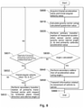
FIG. 8 is a flowchart illustrating an acceleration sensor calibration method according to another embodiment. Referring toFIG. 8 , in operation S800, theacceleration data calibrator 111 may acquire a triaxial acceleration value and a triaxial angular velocity value through thedata acquirer 130. - In operation S810, the
acceleration data calibrator 111 may calculate a gravity vector using a quaternion value calculated based on the acquired triaxial acceleration value and the acquired triaxial angular velocity value. In operation S820, theacceleration data calibrator 111 may obtain angles a and b through primary transformation of an acceleration sensor vector using the gravity vector calculated using the quaternion value, primarily calibrate the acceleration sensor value vector using the derived angles a and b, and store the derived angles a an d b in thememory 120. - Here, in operation S830, the
acceleration data calibrator 111 may verify whether an angle c is calculated in thememory 120. If the angle c is already calculated, theacceleration data calibrator 111 may perform secondary calibration through the angle c, in operation S840. If the angle c is yet to be calculated, theacceleration data calibrator 111 may calculate a value of the angle c based on a horizontal plane vector value of the primarily transformed vector, as described with reference toFIGS. 4A and5A . - The value of the angle c may be calculated only when predetermined conditions are satisfied. For example, only when a magnitude of the horizontal plane vector of the primarily transformed vector exceeds a predetermined value in operation S831, and the triaxial angular velocity value is (0, 0, 0) in operation S832, the
acceleration data calibrator 111 may perform the secondary transformation to derive the angle c, in operation S833. - After calculating the secondarily transformed angle c, the
acceleration data calibrator 111 may store the angle c in thememory 120. Each time the data of theacceleration sensor 131 is read, the primary calibration and the secondary calibration may be performed using the angles a, b and c pre-stored in thememory 120, in operations S820 and S840. In operation S850, information related to a movement of a vehicle may be transmitted to theserver 200 at preset intervals. The information related to the movement of the vehicle may be information calculated based on values measured in real time by theacceleration sensor 131, thegyroscope 132 and theGPS receiver 133, and include, for example, data related to a measured movement such as harsh acceleration, harsh deceleration or harsh turn, or crash data when a crash occurs. The information related to the movement of the vehicle may be provided in the data format as shown in Table 1. - According to another embodiment, an operation of transmitting crash information to a server in response to recognition of a crash of the vehicle may be included.
-
FIG. 9 is a flowchart illustrating an example of recognizing occurrence of a crash and transmitting crash information to a server in a case in which crash data is included in operation S850 ofFIG. 8 . Referring toFIG. 9 , when the accelerationsensor calibration apparatus 100 recognizes a crash of a vehicle in operation S910, theprocessor 110 may operate a timer for 15 seconds, in operation S920. Theprocessor 110 may store a GPS position, a velocity, and an acceleration sensor value in thememory 120 every second until the timer ends, in operation S930. - When the timer ends in operation S940, the
communicator 140 may transmit, to theserver 200, position, velocity and acceleration data of a predetermined period, for example, 15 seconds before the crash and 15 seconds after the crash, in operation S950. In this example, examples of the transmitted data are described in detail above, and thus duplicate description will be omitted here. When the data transmission is completed, the accelerationsensor calibration apparatus 100 may return to operation S800 and execute the series of operations again. -
FIG. 10 is a flowchart illustrating an example of recognizing a vehicle crash according to an embodiment. - Referring to
FIG. 10 , when an external force is applied due to a vehicle crash, an acceleration sensor value may change greatly. In this example, a threshold value for interrupt occurrence caused by the change in the acceleration sensor value may be set. An interrupt may be generated by recognizing the vehicle crash only when exceeding the threshold value. - In detail, in operation S911, a magnitude of a horizontal plane vector of the primarily transformed vector of the measured acceleration vector may be calculated. The horizontal plane vector of the primarily transformed vector may have a z-axial value of the direction of gravity corresponding to "0", and thus a magnitude on a horizontal plane, that is, an xy-axial plane, may be calculated.
- In a case in which the calculated magnitude of the horizontal plane vector of the primarily transformed vector exceeds the predetermined threshold value, the acceleration
sensor calibration apparatus 100 may recognize the vehicle crash and move to operation S920. Conversely, in a case in which the magnitude of the horizontal plane vector of the primarily transformed vector does not exceed the threshold value, the accelerationsensor calibration apparatus 100 may not recognize the vehicle crash and move to S800. - The real-time acceleration sensor calibration apparatus for measuring a movement of a vehicle and the acceleration sensor calibration method using the same according to embodiments are described in detail above. However, the embodiments are not limited thereto, and should be construed broadly within the scope of the following claims.
Claims (11)
- A real-time acceleration sensor calibration apparatus (100) for measuring a movement of a vehicle, the real-time acceleration sensor calibration apparatus (100) comprising:an acceleration sensor (131) configured to measure a triaxial acceleration value;a gyroscope (132) configured to measure a triaxial angular velocity value;an acceleration data calibrator (111) configured to transform a vector of the measured triaxial acceleration value to obtain a first vector by using a gravity vector calculated based on the triaxial acceleration value measured by the acceleration sensor (131) and the triaxial angular velocity value measured by the gyroscope (132); andwhereinthe acceleration data calibrator (111) is configured to perform a secondary transformation on the first vector with respect to a horizontal plane travel direction axis to obtain a second vector, when a magnitude of a horizontal plane vector of the first vector exceeds a predetermined value,wherein the gravity vector is calculated using a quaternion value calculated based on the triaxial acceleration value and the triaxial angular velocity value, anda communicator (140) configured to transmit information related to the movement of the vehicle to a server (200), the information being calculated based on said second vector.
- The real-time acceleration sensor calibration apparatus (100) of claim 1, wherein the secondary transformation is performed when the triaxial angular velocity value is (0, 0, 0).
- The real-time acceleration sensor calibration apparatus (100) of claim 1, wherein the acceleration data calibrator (111) is configured to determine angles a and b for the first vector and an angle c for the second vector, and transform the vector of the triaxial acceleration value measured by the acceleration sensor (131) using the angles a, b and c.
- The real-time acceleration sensor calibration apparatus (100) of claim 3, wherein the angles a and b are derived in real time by the acceleration data calibrator (111) each time the vector of the triaxial acceleration value is measured by the acceleration sensor (131).
- The real-time acceleration sensor calibration apparatus (100) of claim 3, wherein the acceleration data calibrator (111) is configured to calculate the angle c based on a value of the horizontal plane vector of the first vector, if a value of the angle c is yet to be calculated.
- The real-time acceleration sensor calibration apparatus (100) of claim 1, further comprising:a global positioning system, GPS, receiver (133) configured to detect a position of the vehicle,wherein the real-time acceleration sensor calibration apparatus (100) is configured to recognize a crash of the vehicle when a magnitude of a horizontal plane vector of the first vector exceeds a predetermined value, and wherein the real-time acceleration sensor calibration apparatus (100) is configured to transmit data related to the position, a velocity and an acceleration of the vehicle through the communicator (140) to the server (200) in response to the recognition of the crash of the vehicle.
- An acceleration sensor calibration method using a real-time acceleration sensor calibration apparatus (100) for measuring a movement of a vehicle, the acceleration sensor calibration method comprising:measuring a triaxial acceleration value using an acceleration sensor (131);measuring a triaxial angular velocity value using a gyroscope (132);calculating a gravity vector based on the measured triaxial acceleration value and the measured triaxial angular velocity value;transforming a vector of the measured triaxial acceleration value to obtain a first vector by using the calculated gravity vector;after obtaining the first vector, performing a secondary transformation on the first vector with respect to a horizontal plane travel direction axis to obtain a second vector, when a magnitude of a horizontal plane vector of the first vector exceeds a predetermined value; andtransmitting, to a server (200), information related to the movement of the vehicle calculated , the information being calculated based on said second vector,wherein the gravity vector is calculated using a quaternion value calculated based on the triaxial acceleration value and the triaxial angular velocity value.
- The acceleration sensor calibration method of claim 7, wherein the secondary transformation is performed when the triaxial angular velocity value is (0, 0, 0).
- The acceleration sensor calibration method of claim 7, wherein angles a and b for the first vector and an angle c for the second vector are determined, and the vector of the triaxial acceleration value measured by the acceleration sensor (131) is transformed using the angles a, b and c.
- The acceleration sensor calibration method of claim 9, wherein the angles a and b are derived in real time by an acceleration data calibrator (111) each time the vector of the triaxial acceleration value is measured by the acceleration sensor (131).
- The acceleration sensor calibration method of claim 7, further comprising:recognizing a crash of the vehicle when a magnitude of a horizontal plane vector of the first vector exceeds a predetermined value; andtransmitting, to the server (200), data related to the position, a velocity and an acceleration of the vehicle measured by a global positioning system , GPS, receiver (133) in response to the recognition of the crash of the vehicle.
Applications Claiming Priority (1)
| Application Number | Priority Date | Filing Date | Title |
|---|---|---|---|
| PCT/KR2018/002604 WO2019172461A1 (en) | 2018-03-06 | 2018-03-06 | Real-time acceleration sensor correction device for measuring vehicle movement, and acceleration sensor correction method using same |
Publications (3)
| Publication Number | Publication Date |
|---|---|
| EP3763590A1 EP3763590A1 (en) | 2021-01-13 |
| EP3763590A4 EP3763590A4 (en) | 2021-03-17 |
| EP3763590B1 true EP3763590B1 (en) | 2022-01-19 |
Family
ID=67842015
Family Applications (1)
| Application Number | Title | Priority Date | Filing Date |
|---|---|---|---|
| EP18909077.2A Active EP3763590B1 (en) | 2018-03-06 | 2018-03-06 | Real-time acceleration sensor correction device for measuring vehicle movement, and acceleration sensor correction method using same |
Country Status (4)
| Country | Link |
|---|---|
| US (1) | US10810861B2 (en) |
| EP (1) | EP3763590B1 (en) |
| KR (1) | KR102304006B1 (en) |
| WO (1) | WO2019172461A1 (en) |
Families Citing this family (7)
| Publication number | Priority date | Publication date | Assignee | Title |
|---|---|---|---|---|
| JPWO2020158485A1 (en) * | 2019-01-28 | 2021-12-02 | パナソニックIpマネジメント株式会社 | Combined sensor and angular velocity correction method |
| US12259724B2 (en) | 2019-08-27 | 2025-03-25 | Crown Equipment Corporation | Adaptive acceleration for materials handling vehicle |
| CN111337051B (en) * | 2020-03-17 | 2022-02-01 | 阿波罗智联(北京)科技有限公司 | Method and device for calibrating forward axis of vehicle accelerometer |
| US11827503B2 (en) * | 2020-03-18 | 2023-11-28 | Crown Equipment Corporation | Adaptive acceleration for materials handling vehicle |
| WO2022098402A1 (en) | 2020-11-03 | 2022-05-12 | Crown Equipment Corporation | Adaptive acceleration for materials handling vehicle |
| CN113928327B (en) * | 2021-09-29 | 2024-04-05 | 深圳市麦谷科技有限公司 | Method and system for detecting three emergency events |
| DE102024206153A1 (en) * | 2024-07-01 | 2026-01-08 | Zf Friedrichshafen Ag | Device, system and method for determining the acceleration due to gravity based on sensor data from an acceleration sensor of a vehicle. |
Family Cites Families (16)
| Publication number | Priority date | Publication date | Assignee | Title |
|---|---|---|---|---|
| JPH10123171A (en) * | 1996-10-18 | 1998-05-15 | Hokuriku Electric Ind Co Ltd | Diagnosis method and self-diagnosis device of three-axis acceleration sensor |
| JP2000187042A (en) * | 1998-10-16 | 2000-07-04 | Japan Aviation Electronics Industry Ltd | Method for correcting misalignment of multi-dimensional acceleration sensor and multi-dimensional acceleration measuring device equipped with the sensor |
| US20160047675A1 (en) * | 2005-04-19 | 2016-02-18 | Tanenhaus & Associates, Inc. | Inertial Measurement and Navigation System And Method Having Low Drift MEMS Gyroscopes And Accelerometers Operable In GPS Denied Environments |
| JP4736866B2 (en) * | 2005-04-28 | 2011-07-27 | 株式会社デンソー | Navigation device |
| KR101095156B1 (en) | 2005-11-09 | 2011-12-16 | 주식회사 현대오토넷 | How to provide emergency rescue service using telematics system |
| US7463953B1 (en) * | 2007-06-22 | 2008-12-09 | Volkswagen Ag | Method for determining a tilt angle of a vehicle |
| US8589015B2 (en) * | 2010-02-12 | 2013-11-19 | Webtech Wireless Inc. | Vehicle sensor calibration for determining vehicle dynamics |
| RU2597658C2 (en) * | 2010-11-08 | 2016-09-20 | ЭлпайнРиплей, Инк. | Device and method of calibrating gyro sensors |
| US9803983B2 (en) * | 2010-12-03 | 2017-10-31 | Qualcomm Incorporated | Inertial sensor aided heading and positioning for GNSS vehicle navigation |
| US9810549B2 (en) * | 2011-01-06 | 2017-11-07 | University Of Utah Research Foundation | Systems, methods, and apparatus for calibration of and three-dimensional tracking of intermittent motion with an inertial measurement unit |
| US8768560B2 (en) * | 2011-10-04 | 2014-07-01 | Webtech Wireless Inc. | Method and system for performing calibration of an accelerometer of a telematics device during installation in a vehicle |
| KR101250215B1 (en) * | 2012-05-31 | 2013-04-03 | 삼성탈레스 주식회사 | Pedestrian dead-reckoning system using kalman filter and walking state estimation algorithm and method for height estimation thereof |
| KR101456576B1 (en) * | 2013-07-10 | 2014-10-31 | 한국원자력연구원 | Attitude estimation apparatus and method in in-pipe robot |
| KR101658101B1 (en) * | 2014-12-09 | 2016-09-21 | 주식회사 동부엔티에스 | Accident Type Judgment Method And System for Vehicle Accident Pattern Using A 3-Axis Acceleration Sensor, Apparatus |
| US10746551B2 (en) * | 2015-10-15 | 2020-08-18 | Mitsubishi Electric Corporation | Positioning apparatus and positioning method |
| KR101739390B1 (en) * | 2015-12-11 | 2017-05-24 | 국방과학연구소 | Method for improving the accuracy of self-alignment about the inertial navigation system through gravitational error compensation |
-
2018
- 2018-03-06 KR KR1020207021214A patent/KR102304006B1/en active Active
- 2018-03-06 EP EP18909077.2A patent/EP3763590B1/en active Active
- 2018-03-06 WO PCT/KR2018/002604 patent/WO2019172461A1/en not_active Ceased
- 2018-04-09 US US15/948,063 patent/US10810861B2/en active Active
Also Published As
| Publication number | Publication date |
|---|---|
| EP3763590A1 (en) | 2021-01-13 |
| US20190279493A1 (en) | 2019-09-12 |
| EP3763590A4 (en) | 2021-03-17 |
| KR20200094793A (en) | 2020-08-07 |
| WO2019172461A1 (en) | 2019-09-12 |
| KR102304006B1 (en) | 2021-09-23 |
| US10810861B2 (en) | 2020-10-20 |
Similar Documents
| Publication | Publication Date | Title |
|---|---|---|
| EP3763590B1 (en) | Real-time acceleration sensor correction device for measuring vehicle movement, and acceleration sensor correction method using same | |
| US11669054B2 (en) | Method and apparatus for operating mobile platform | |
| US12405112B2 (en) | Inertial navigation system capable of dead reckoning in vehicles | |
| US8645063B2 (en) | Method and system for initial quaternion and attitude estimation | |
| US20130316310A1 (en) | Methods for determining orientation of a moving vehicle | |
| US20160223334A1 (en) | Method and apparatus for determination of misalignment between device and vessel using acceleration/deceleration | |
| US11117589B2 (en) | System and method for determining roadway bank angle | |
| US8892385B2 (en) | System and method for use with an accelerometer to determine a frame of reference | |
| US11385059B2 (en) | Method for determining heading of unmanned aerial vehicle and unmanned aerial vehicle | |
| CN112859139B (en) | Method, device and electronic equipment for attitude measurement | |
| CN113063425B (en) | Vehicle positioning method and device, electronic equipment and storage medium | |
| EP3045919A1 (en) | System and method for estimating speed of a vehicle | |
| CN107764273B (en) | Vehicle navigation positioning method and system | |
| EP4394326A1 (en) | Inertial navigation initial-alignment method and apparatus applied to oblique measurement, and device | |
| KR101921055B1 (en) | Inspecting system of vehicle accident and method therefor | |
| JP4825064B2 (en) | Position measuring system and position measuring method | |
| US20240004024A1 (en) | Electronic device for estimating relative position and pose and operating method of the same | |
| JP6154951B1 (en) | Velocity measuring device, position measuring device, velocity measuring method and program | |
| CN112595325B (en) | Initial position determining method, device, electronic equipment and storage medium | |
| CN114415222A (en) | Navigation method, navigation device and electronic equipment | |
| KR102612606B1 (en) | Method and apparatus of angle compensation for flight dynamics, flying attitude simulation system and flying attitude simulation method of ground station by using angle compensation for flight dynamics | |
| US10274317B2 (en) | Method and apparatus for determination of misalignment between device and vessel using radius of rotation | |
| CN118688841A (en) | Vehicle posture information acquisition method, device, electronic equipment and medium | |
| CN111397602A (en) | High-precision positioning method and device integrating broadband electromagnetic fingerprint and integrated navigation | |
| US11507113B2 (en) | Aerial vehicle sensor calibration systems and methods |
Legal Events
| Date | Code | Title | Description |
|---|---|---|---|
| STAA | Information on the status of an ep patent application or granted ep patent |
Free format text: STATUS: THE INTERNATIONAL PUBLICATION HAS BEEN MADE |
|
| PUAI | Public reference made under article 153(3) epc to a published international application that has entered the european phase |
Free format text: ORIGINAL CODE: 0009012 |
|
| STAA | Information on the status of an ep patent application or granted ep patent |
Free format text: STATUS: REQUEST FOR EXAMINATION WAS MADE |
|
| 17P | Request for examination filed |
Effective date: 20200803 |
|
| AK | Designated contracting states |
Kind code of ref document: A1 Designated state(s): AL AT BE BG CH CY CZ DE DK EE ES FI FR GB GR HR HU IE IS IT LI LT LU LV MC MK MT NL NO PL PT RO RS SE SI SK SM TR |
|
| AX | Request for extension of the european patent |
Extension state: BA ME |
|
| A4 | Supplementary search report drawn up and despatched |
Effective date: 20210215 |
|
| RIC1 | Information provided on ipc code assigned before grant |
Ipc: B60W 40/09 20120101ALI20210209BHEP Ipc: B60W 50/02 20120101AFI20210209BHEP Ipc: G01S 19/14 20100101ALI20210209BHEP Ipc: G01C 19/00 20130101ALI20210209BHEP Ipc: G01P 3/44 20060101ALI20210209BHEP Ipc: B60W 40/107 20120101ALI20210209BHEP Ipc: G01P 15/18 20130101ALI20210209BHEP Ipc: G01P 21/02 20060101ALI20210209BHEP |
|
| DAV | Request for validation of the european patent (deleted) | ||
| DAX | Request for extension of the european patent (deleted) | ||
| GRAP | Despatch of communication of intention to grant a patent |
Free format text: ORIGINAL CODE: EPIDOSNIGR1 |
|
| STAA | Information on the status of an ep patent application or granted ep patent |
Free format text: STATUS: GRANT OF PATENT IS INTENDED |
|
| INTG | Intention to grant announced |
Effective date: 20210908 |
|
| GRAS | Grant fee paid |
Free format text: ORIGINAL CODE: EPIDOSNIGR3 |
|
| GRAA | (expected) grant |
Free format text: ORIGINAL CODE: 0009210 |
|
| STAA | Information on the status of an ep patent application or granted ep patent |
Free format text: STATUS: THE PATENT HAS BEEN GRANTED |
|
| AK | Designated contracting states |
Kind code of ref document: B1 Designated state(s): AL AT BE BG CH CY CZ DE DK EE ES FI FR GB GR HR HU IE IS IT LI LT LU LV MC MK MT NL NO PL PT RO RS SE SI SK SM TR |
|
| REG | Reference to a national code |
Ref country code: GB Ref legal event code: FG4D |
|
| REG | Reference to a national code |
Ref country code: CH Ref legal event code: EP |
|
| REG | Reference to a national code |
Ref country code: DE Ref legal event code: R096 Ref document number: 602018029923 Country of ref document: DE |
|
| REG | Reference to a national code |
Ref country code: AT Ref legal event code: REF Ref document number: 1463638 Country of ref document: AT Kind code of ref document: T Effective date: 20220215 |
|
| REG | Reference to a national code |
Ref country code: IE Ref legal event code: FG4D |
|
| REG | Reference to a national code |
Ref country code: LT Ref legal event code: MG9D |
|
| REG | Reference to a national code |
Ref country code: NL Ref legal event code: MP Effective date: 20220119 |
|
| REG | Reference to a national code |
Ref country code: AT Ref legal event code: MK05 Ref document number: 1463638 Country of ref document: AT Kind code of ref document: T Effective date: 20220119 |
|
| PG25 | Lapsed in a contracting state [announced via postgrant information from national office to epo] |
Ref country code: NL Free format text: LAPSE BECAUSE OF FAILURE TO SUBMIT A TRANSLATION OF THE DESCRIPTION OR TO PAY THE FEE WITHIN THE PRESCRIBED TIME-LIMIT Effective date: 20220119 |
|
| PG25 | Lapsed in a contracting state [announced via postgrant information from national office to epo] |
Ref country code: SE Free format text: LAPSE BECAUSE OF FAILURE TO SUBMIT A TRANSLATION OF THE DESCRIPTION OR TO PAY THE FEE WITHIN THE PRESCRIBED TIME-LIMIT Effective date: 20220119 Ref country code: RS Free format text: LAPSE BECAUSE OF FAILURE TO SUBMIT A TRANSLATION OF THE DESCRIPTION OR TO PAY THE FEE WITHIN THE PRESCRIBED TIME-LIMIT Effective date: 20220119 Ref country code: PT Free format text: LAPSE BECAUSE OF FAILURE TO SUBMIT A TRANSLATION OF THE DESCRIPTION OR TO PAY THE FEE WITHIN THE PRESCRIBED TIME-LIMIT Effective date: 20220519 Ref country code: NO Free format text: LAPSE BECAUSE OF FAILURE TO SUBMIT A TRANSLATION OF THE DESCRIPTION OR TO PAY THE FEE WITHIN THE PRESCRIBED TIME-LIMIT Effective date: 20220419 Ref country code: LT Free format text: LAPSE BECAUSE OF FAILURE TO SUBMIT A TRANSLATION OF THE DESCRIPTION OR TO PAY THE FEE WITHIN THE PRESCRIBED TIME-LIMIT Effective date: 20220119 Ref country code: HR Free format text: LAPSE BECAUSE OF FAILURE TO SUBMIT A TRANSLATION OF THE DESCRIPTION OR TO PAY THE FEE WITHIN THE PRESCRIBED TIME-LIMIT Effective date: 20220119 Ref country code: ES Free format text: LAPSE BECAUSE OF FAILURE TO SUBMIT A TRANSLATION OF THE DESCRIPTION OR TO PAY THE FEE WITHIN THE PRESCRIBED TIME-LIMIT Effective date: 20220119 Ref country code: BG Free format text: LAPSE BECAUSE OF FAILURE TO SUBMIT A TRANSLATION OF THE DESCRIPTION OR TO PAY THE FEE WITHIN THE PRESCRIBED TIME-LIMIT Effective date: 20220419 |
|
| PG25 | Lapsed in a contracting state [announced via postgrant information from national office to epo] |
Ref country code: PL Free format text: LAPSE BECAUSE OF FAILURE TO SUBMIT A TRANSLATION OF THE DESCRIPTION OR TO PAY THE FEE WITHIN THE PRESCRIBED TIME-LIMIT Effective date: 20220119 Ref country code: LV Free format text: LAPSE BECAUSE OF FAILURE TO SUBMIT A TRANSLATION OF THE DESCRIPTION OR TO PAY THE FEE WITHIN THE PRESCRIBED TIME-LIMIT Effective date: 20220119 Ref country code: GR Free format text: LAPSE BECAUSE OF FAILURE TO SUBMIT A TRANSLATION OF THE DESCRIPTION OR TO PAY THE FEE WITHIN THE PRESCRIBED TIME-LIMIT Effective date: 20220420 Ref country code: FI Free format text: LAPSE BECAUSE OF FAILURE TO SUBMIT A TRANSLATION OF THE DESCRIPTION OR TO PAY THE FEE WITHIN THE PRESCRIBED TIME-LIMIT Effective date: 20220119 Ref country code: AT Free format text: LAPSE BECAUSE OF FAILURE TO SUBMIT A TRANSLATION OF THE DESCRIPTION OR TO PAY THE FEE WITHIN THE PRESCRIBED TIME-LIMIT Effective date: 20220119 |
|
| PG25 | Lapsed in a contracting state [announced via postgrant information from national office to epo] |
Ref country code: IS Free format text: LAPSE BECAUSE OF FAILURE TO SUBMIT A TRANSLATION OF THE DESCRIPTION OR TO PAY THE FEE WITHIN THE PRESCRIBED TIME-LIMIT Effective date: 20220519 |
|
| REG | Reference to a national code |
Ref country code: DE Ref legal event code: R097 Ref document number: 602018029923 Country of ref document: DE |
|
| PG25 | Lapsed in a contracting state [announced via postgrant information from national office to epo] |
Ref country code: SM Free format text: LAPSE BECAUSE OF FAILURE TO SUBMIT A TRANSLATION OF THE DESCRIPTION OR TO PAY THE FEE WITHIN THE PRESCRIBED TIME-LIMIT Effective date: 20220119 Ref country code: SK Free format text: LAPSE BECAUSE OF FAILURE TO SUBMIT A TRANSLATION OF THE DESCRIPTION OR TO PAY THE FEE WITHIN THE PRESCRIBED TIME-LIMIT Effective date: 20220119 Ref country code: RO Free format text: LAPSE BECAUSE OF FAILURE TO SUBMIT A TRANSLATION OF THE DESCRIPTION OR TO PAY THE FEE WITHIN THE PRESCRIBED TIME-LIMIT Effective date: 20220119 Ref country code: MC Free format text: LAPSE BECAUSE OF FAILURE TO SUBMIT A TRANSLATION OF THE DESCRIPTION OR TO PAY THE FEE WITHIN THE PRESCRIBED TIME-LIMIT Effective date: 20220119 Ref country code: EE Free format text: LAPSE BECAUSE OF FAILURE TO SUBMIT A TRANSLATION OF THE DESCRIPTION OR TO PAY THE FEE WITHIN THE PRESCRIBED TIME-LIMIT Effective date: 20220119 Ref country code: DK Free format text: LAPSE BECAUSE OF FAILURE TO SUBMIT A TRANSLATION OF THE DESCRIPTION OR TO PAY THE FEE WITHIN THE PRESCRIBED TIME-LIMIT Effective date: 20220119 Ref country code: CZ Free format text: LAPSE BECAUSE OF FAILURE TO SUBMIT A TRANSLATION OF THE DESCRIPTION OR TO PAY THE FEE WITHIN THE PRESCRIBED TIME-LIMIT Effective date: 20220119 |
|
| REG | Reference to a national code |
Ref country code: CH Ref legal event code: PL |
|
| PLBE | No opposition filed within time limit |
Free format text: ORIGINAL CODE: 0009261 |
|
| STAA | Information on the status of an ep patent application or granted ep patent |
Free format text: STATUS: NO OPPOSITION FILED WITHIN TIME LIMIT |
|
| PG25 | Lapsed in a contracting state [announced via postgrant information from national office to epo] |
Ref country code: AL Free format text: LAPSE BECAUSE OF FAILURE TO SUBMIT A TRANSLATION OF THE DESCRIPTION OR TO PAY THE FEE WITHIN THE PRESCRIBED TIME-LIMIT Effective date: 20220119 |
|
| REG | Reference to a national code |
Ref country code: BE Ref legal event code: MM Effective date: 20220331 |
|
| 26N | No opposition filed |
Effective date: 20221020 |
|
| PG25 | Lapsed in a contracting state [announced via postgrant information from national office to epo] |
Ref country code: LU Free format text: LAPSE BECAUSE OF NON-PAYMENT OF DUE FEES Effective date: 20220306 Ref country code: LI Free format text: LAPSE BECAUSE OF NON-PAYMENT OF DUE FEES Effective date: 20220331 Ref country code: IE Free format text: LAPSE BECAUSE OF NON-PAYMENT OF DUE FEES Effective date: 20220306 Ref country code: CH Free format text: LAPSE BECAUSE OF NON-PAYMENT OF DUE FEES Effective date: 20220331 |
|
| PG25 | Lapsed in a contracting state [announced via postgrant information from national office to epo] |
Ref country code: SI Free format text: LAPSE BECAUSE OF FAILURE TO SUBMIT A TRANSLATION OF THE DESCRIPTION OR TO PAY THE FEE WITHIN THE PRESCRIBED TIME-LIMIT Effective date: 20220119 Ref country code: BE Free format text: LAPSE BECAUSE OF NON-PAYMENT OF DUE FEES Effective date: 20220331 |
|
| PG25 | Lapsed in a contracting state [announced via postgrant information from national office to epo] |
Ref country code: IT Free format text: LAPSE BECAUSE OF FAILURE TO SUBMIT A TRANSLATION OF THE DESCRIPTION OR TO PAY THE FEE WITHIN THE PRESCRIBED TIME-LIMIT Effective date: 20220119 |
|
| PG25 | Lapsed in a contracting state [announced via postgrant information from national office to epo] |
Ref country code: MK Free format text: LAPSE BECAUSE OF FAILURE TO SUBMIT A TRANSLATION OF THE DESCRIPTION OR TO PAY THE FEE WITHIN THE PRESCRIBED TIME-LIMIT Effective date: 20220119 Ref country code: CY Free format text: LAPSE BECAUSE OF FAILURE TO SUBMIT A TRANSLATION OF THE DESCRIPTION OR TO PAY THE FEE WITHIN THE PRESCRIBED TIME-LIMIT Effective date: 20220119 |
|
| PG25 | Lapsed in a contracting state [announced via postgrant information from national office to epo] |
Ref country code: HU Free format text: LAPSE BECAUSE OF FAILURE TO SUBMIT A TRANSLATION OF THE DESCRIPTION OR TO PAY THE FEE WITHIN THE PRESCRIBED TIME-LIMIT; INVALID AB INITIO Effective date: 20180306 |
|
| PG25 | Lapsed in a contracting state [announced via postgrant information from national office to epo] |
Ref country code: TR Free format text: LAPSE BECAUSE OF FAILURE TO SUBMIT A TRANSLATION OF THE DESCRIPTION OR TO PAY THE FEE WITHIN THE PRESCRIBED TIME-LIMIT Effective date: 20220119 |
|
| PG25 | Lapsed in a contracting state [announced via postgrant information from national office to epo] |
Ref country code: MT Free format text: LAPSE BECAUSE OF FAILURE TO SUBMIT A TRANSLATION OF THE DESCRIPTION OR TO PAY THE FEE WITHIN THE PRESCRIBED TIME-LIMIT Effective date: 20220119 |
|
| REG | Reference to a national code |
Ref country code: DE Ref legal event code: R081 Ref document number: 602018029923 Country of ref document: DE Owner name: ST SUNLAB LTD., KR Free format text: FORMER OWNER: SUNTECH INTERNATIONAL LTD., SEOUL, KR |
|
| PGFP | Annual fee paid to national office [announced via postgrant information from national office to epo] |
Ref country code: GB Payment date: 20260319 Year of fee payment: 9 |
|
| PGFP | Annual fee paid to national office [announced via postgrant information from national office to epo] |
Ref country code: DE Payment date: 20260319 Year of fee payment: 9 |
|
| PGFP | Annual fee paid to national office [announced via postgrant information from national office to epo] |
Ref country code: FR Payment date: 20260319 Year of fee payment: 9 |