EP3763569A1 - Aircraft passenger light - Google Patents
Aircraft passenger light Download PDFInfo
- Publication number
- EP3763569A1 EP3763569A1 EP19186071.7A EP19186071A EP3763569A1 EP 3763569 A1 EP3763569 A1 EP 3763569A1 EP 19186071 A EP19186071 A EP 19186071A EP 3763569 A1 EP3763569 A1 EP 3763569A1
- Authority
- EP
- European Patent Office
- Prior art keywords
- light
- halo
- light source
- reading
- aircraft passenger
- Prior art date
- Legal status (The legal status is an assumption and is not a legal conclusion. Google has not performed a legal analysis and makes no representation as to the accuracy of the status listed.)
- Granted
Links
Images


Classifications
-
- B—PERFORMING OPERATIONS; TRANSPORTING
- B60—VEHICLES IN GENERAL
- B60Q—ARRANGEMENT OF SIGNALLING OR LIGHTING DEVICES, THE MOUNTING OR SUPPORTING THEREOF OR CIRCUITS THEREFOR, FOR VEHICLES IN GENERAL
- B60Q3/00—Arrangement of lighting devices for vehicle interiors; Lighting devices specially adapted for vehicle interiors
- B60Q3/40—Arrangement of lighting devices for vehicle interiors; Lighting devices specially adapted for vehicle interiors specially adapted for specific vehicle types
- B60Q3/41—Arrangement of lighting devices for vehicle interiors; Lighting devices specially adapted for vehicle interiors specially adapted for specific vehicle types for mass transit vehicles, e.g. buses
- B60Q3/44—Spotlighting, e.g. reading lamps
-
- B—PERFORMING OPERATIONS; TRANSPORTING
- B60—VEHICLES IN GENERAL
- B60Q—ARRANGEMENT OF SIGNALLING OR LIGHTING DEVICES, THE MOUNTING OR SUPPORTING THEREOF OR CIRCUITS THEREFOR, FOR VEHICLES IN GENERAL
- B60Q3/00—Arrangement of lighting devices for vehicle interiors; Lighting devices specially adapted for vehicle interiors
- B60Q3/40—Arrangement of lighting devices for vehicle interiors; Lighting devices specially adapted for vehicle interiors specially adapted for specific vehicle types
- B60Q3/41—Arrangement of lighting devices for vehicle interiors; Lighting devices specially adapted for vehicle interiors specially adapted for specific vehicle types for mass transit vehicles, e.g. buses
- B60Q3/47—Circuits; Control arrangements
-
- B—PERFORMING OPERATIONS; TRANSPORTING
- B60—VEHICLES IN GENERAL
- B60Q—ARRANGEMENT OF SIGNALLING OR LIGHTING DEVICES, THE MOUNTING OR SUPPORTING THEREOF OR CIRCUITS THEREFOR, FOR VEHICLES IN GENERAL
- B60Q3/00—Arrangement of lighting devices for vehicle interiors; Lighting devices specially adapted for vehicle interiors
- B60Q3/60—Arrangement of lighting devices for vehicle interiors; Lighting devices specially adapted for vehicle interiors characterised by optical aspects
-
- B—PERFORMING OPERATIONS; TRANSPORTING
- B64—AIRCRAFT; AVIATION; COSMONAUTICS
- B64D—EQUIPMENT FOR FITTING IN OR TO AIRCRAFT; FLIGHT SUITS; PARACHUTES; ARRANGEMENT OR MOUNTING OF POWER PLANTS OR PROPULSION TRANSMISSIONS IN AIRCRAFT
- B64D11/00—Passenger or crew accommodation; Flight-deck installations not otherwise provided for
-
- F—MECHANICAL ENGINEERING; LIGHTING; HEATING; WEAPONS; BLASTING
- F21—LIGHTING
- F21V—FUNCTIONAL FEATURES OR DETAILS OF LIGHTING DEVICES OR SYSTEMS THEREOF; STRUCTURAL COMBINATIONS OF LIGHTING DEVICES WITH OTHER ARTICLES, NOT OTHERWISE PROVIDED FOR
- F21V7/00—Reflectors for light sources
- F21V7/04—Optical design
- F21V7/06—Optical design with parabolic curvature
-
- B—PERFORMING OPERATIONS; TRANSPORTING
- B64—AIRCRAFT; AVIATION; COSMONAUTICS
- B64D—EQUIPMENT FOR FITTING IN OR TO AIRCRAFT; FLIGHT SUITS; PARACHUTES; ARRANGEMENT OR MOUNTING OF POWER PLANTS OR PROPULSION TRANSMISSIONS IN AIRCRAFT
- B64D11/00—Passenger or crew accommodation; Flight-deck installations not otherwise provided for
- B64D2011/0038—Illumination systems for cabins as a whole
-
- B—PERFORMING OPERATIONS; TRANSPORTING
- B64—AIRCRAFT; AVIATION; COSMONAUTICS
- B64D—EQUIPMENT FOR FITTING IN OR TO AIRCRAFT; FLIGHT SUITS; PARACHUTES; ARRANGEMENT OR MOUNTING OF POWER PLANTS OR PROPULSION TRANSMISSIONS IN AIRCRAFT
- B64D11/00—Passenger or crew accommodation; Flight-deck installations not otherwise provided for
- B64D2011/0053—Cabin passenger reading lights
-
- B—PERFORMING OPERATIONS; TRANSPORTING
- B64—AIRCRAFT; AVIATION; COSMONAUTICS
- B64D—EQUIPMENT FOR FITTING IN OR TO AIRCRAFT; FLIGHT SUITS; PARACHUTES; ARRANGEMENT OR MOUNTING OF POWER PLANTS OR PROPULSION TRANSMISSIONS IN AIRCRAFT
- B64D2203/00—Aircraft or airfield lights using LEDs
-
- F—MECHANICAL ENGINEERING; LIGHTING; HEATING; WEAPONS; BLASTING
- F21—LIGHTING
- F21W—INDEXING SCHEME ASSOCIATED WITH SUBCLASSES F21K, F21L, F21S and F21V, RELATING TO USES OR APPLICATIONS OF LIGHTING DEVICES OR SYSTEMS
- F21W2106/00—Interior vehicle lighting devices
-
- F—MECHANICAL ENGINEERING; LIGHTING; HEATING; WEAPONS; BLASTING
- F21—LIGHTING
- F21W—INDEXING SCHEME ASSOCIATED WITH SUBCLASSES F21K, F21L, F21S and F21V, RELATING TO USES OR APPLICATIONS OF LIGHTING DEVICES OR SYSTEMS
- F21W2107/00—Use or application of lighting devices on or in particular types of vehicles
- F21W2107/30—Use or application of lighting devices on or in particular types of vehicles for aircraft
-
- F—MECHANICAL ENGINEERING; LIGHTING; HEATING; WEAPONS; BLASTING
- F21—LIGHTING
- F21Y—INDEXING SCHEME ASSOCIATED WITH SUBCLASSES F21K, F21L, F21S and F21V, RELATING TO THE FORM OR THE KIND OF THE LIGHT SOURCES OR OF THE COLOUR OF THE LIGHT EMITTED
- F21Y2105/00—Planar light sources
- F21Y2105/10—Planar light sources comprising a two-dimensional [2D] array of point-like light-generating elements
- F21Y2105/14—Planar light sources comprising a two-dimensional [2D] array of point-like light-generating elements characterised by the overall shape of the two-dimensional [2D] array
- F21Y2105/18—Planar light sources comprising a two-dimensional [2D] array of point-like light-generating elements characterised by the overall shape of the two-dimensional [2D] array annular; polygonal other than square or rectangular, e.g. for spotlights or for generating an axially symmetrical light beam
-
- F—MECHANICAL ENGINEERING; LIGHTING; HEATING; WEAPONS; BLASTING
- F21—LIGHTING
- F21Y—INDEXING SCHEME ASSOCIATED WITH SUBCLASSES F21K, F21L, F21S and F21V, RELATING TO THE FORM OR THE KIND OF THE LIGHT SOURCES OR OF THE COLOUR OF THE LIGHT EMITTED
- F21Y2113/00—Combination of light sources
- F21Y2113/10—Combination of light sources of different colours
- F21Y2113/13—Combination of light sources of different colours comprising an assembly of point-like light sources
-
- F—MECHANICAL ENGINEERING; LIGHTING; HEATING; WEAPONS; BLASTING
- F21—LIGHTING
- F21Y—INDEXING SCHEME ASSOCIATED WITH SUBCLASSES F21K, F21L, F21S and F21V, RELATING TO THE FORM OR THE KIND OF THE LIGHT SOURCES OR OF THE COLOUR OF THE LIGHT EMITTED
- F21Y2115/00—Light-generating elements of semiconductor light sources
- F21Y2115/10—Light-emitting diodes [LED]
Definitions
- the present invention is in the field of lighting devices.
- the present invention is in the field of lighting devices for aircraft and aircraft equipped with such lighting devices.
- the present invention is in the field of interior aircraft lighting systems.
- Modern aircraft comprise a variety of interior aircraft lights, including cabin illumination lights, aircraft passenger lights, exit sign lights, etc.
- An individually switchable aircraft passenger light (“reading light”) is usually provided over and associated with each passenger seat.
- Exemplary embodiments of the invention include an aircraft passenger light, comprising a reading light unit and a halo light unit.
- the reading light unit comprises at least one reading light source and is configured for emitting a targeted reading light output.
- the halo light unit comprises at least one halo light source and is configured for emitting a ring-shaped halo light output, at least partly surrounding the targeted reading light output.
- the halo light unit adds additional functionality to the aircraft passenger light as it allows using the aircraft passenger light for additional purposes, in particular for indicating and signaling purposes, without occupying substantial additional space within the passenger cabin of the aircraft, in particular without dedicating an additional location within the passenger cabin of the aircraft to the additional functionality.
- the halo light unit may for example be used for indicating acoustic announcements and/or for providing information related to an associated passenger seat.
- the halo light unit is configured for emitting a ring-shaped halo light output, completely surrounding the targeted reading light output.
- the halo light output only partly surrounds the targeted reading light output or surrounds the targeted reading light output in an interrupted manner, such as interrupted by mounting bars or strips, connecting the reading light unit, in particular a reflector thereof, to a housing of the aircraft passenger light on a light emission side of the aircraft passenger light. All of completely ring-shaped, partly ring-shaped or interrupted ring-shaped halo light outputs are encompassed by the terminology of the ring-shaped halo light output at least partly surrounding the targeted reading light output.
- the reading light unit and the halo light unit have a common light emission plane, through which the targeted reading light output and the ring-shaped halo light output are emitted when the reading light unit and/or the halo light unit are operated.
- the reading light unit and the halo light unit may emit their respective light outputs in similar directions, in particular towards the associated passenger seat so that both light outputs are easily and reliably visible by a passenger sitting on said passenger seat.
- the reading light output may be more collimated than then halo light output.
- the opening angle of the reading light output may be more narrow than the opening angle of the halo light output.
- the halo light output in particular is not intended for illuminating of a target surface.
- the halo light output may be visible from outside the passenger's personal space as well.
- the halo light output may be visible for a passenger walking by the passenger seat associated with the aircraft passenger light in question.
- the reading light unit and/or the halo light unit comprise a transparent cover for protecting the at least one reading light source and the at least one halo light source, respectively.
- the cover further protects the passenger from burning himself/herself by touching the potentially hot light sources and/or sensitive optical surfaces.
- Individual covers may be provided for the reading light unit and the halo light unit, respectively.
- a single cover, covering both the reading light unit and the halo light unit, may be provided.
- the reading light unit comprises a reflector configured for directing the light output from the at least one reading light source towards the passenger seat. In this way, an efficient illumination of the area above the passenger seat may be achieved.
- the reflector may be rotationally symmetric with respect to a main light-emission axis of the reading light unit.
- the reflector may in particular a parabolic reflector.
- a parabolic reflector is easy to produce at low costs and allows for a very efficient illumination of the area above the passenger seat.
- the reflector may also be spherical or may be comprised of multiple spherical sections or may have any other suitable shape for concentrating the light from the at least one reading light source.
- the reflector surrounds the at least one reading light source. Such a configuration results in an efficient reflection of the light, emitted by the at least one reading light source into various initial directions.
- the at least one halo light source is arranged outside the reflector.
- Such a configuration allows for shaping the halo light output from the light emitted from the at least one halo light source independently of shaping the halo light output from the light emitted by the at least one reading light source. This adds additional flexibility to forming the total light output of the aircraft passenger light.
- At least one of an inner surface and an outer surface of the reflector are reflective, in order to avoid absorbing considerable amounts of the light emitted by the at least one reading light source and the at least one halo light source, respectively.
- the reflector may be made of a reflective material, such as metal.
- the reflector also may be coated with a reflective coating, in particular with a metallic coating.
- the aircraft passenger light comprises at least one outer wall arranged outside the reflector.
- the outer wall in particular may form a halo light chamber between the outer surface of the reflector and the outer wall.
- the at least one halo light source may be arranged within said halo light chamber.
- an inner side of the outer wall, facing the halo light chamber is reflective or diffusely reflective, in order to avoid that a considerable amount of the light emitted by the at least one halo light source is absorbed by the outer wall.
- the inner side of the outer wall in particular may have a white color, or it may be coated with a reflective or diffusely reflective, in particular white, coating.
- the combination of a reflective outer surface of the reflector and a diffusely reflective, in particular white, inner side of the outer wall may provide for a particularly uniformly distributed and fairly wide angled halo light output, such that a pleasant appearance and an extended visibility of the halo light unit may be achieved.
- the at least one reading light source and the at least one halo light source are arranged on a common circuit board, in particular on a common printed circuit board.
- the at least one reading light source and/or the at least one halo light source is or comprises an LED. LEDs provide efficient and reliable light sources at low costs.
- the at least one reading light source is configured for emitting white light, in particular white light having a correlated color temperature of more than 2500 K.
- White light is preferably used for reading lights.
- the at least one halo light source is configured for emitting white light, in particular whitish light having a correlated color temperature of more than 2500 K, or light having a different color, in particular, red, green, blue, yellow, purple or orange light.
- the halo light unit comprises a plurality of independently controllable halo light sources of different colors, particularly at least three independently controllable halo light sources of different colors, such as independently controllable red, green, and blue halo light sources.
- a configuration allows the halo light unit to emit light of almost arbitrary color by selectively activating one or more of the halo light sources, providing a large flexibility of the light emitted by the aircraft passenger light.
- Exemplary embodiments of the invention also include an aircraft comprising at least one aircraft passenger light according to any of the exemplary embodiments of the invention, as described above.
- Exemplary embodiments of the invention in particular include an aircraft comprising a passenger cabin and at least one aircraft passenger light according to an exemplary embodiment of the invention arranged within the passenger cabin.
- a plurality of passenger seats and aircraft passenger lights may be arranged within the passenger cabin.
- Each aircraft passenger light may be associated with one of the passenger seats, respectively; i.e. the reading light unit of each aircraft passenger light may be configured for illuminating a space above the associated passenger seat, in order to provide a personal reading light for a passenger sitting on the associated passenger seat.
- Exemplary embodiments of the invention further include a method of operating an aircraft passenger light according to any of the exemplary embodiments of the invention, as described above, wherein the method comprises operating the at least one halo light source independently from the at least one reading light source. This allows using the halo light unit for indication purposes independently of the reading light source.
- Exemplary embodiments of the method in particular include selecting a color of the halo light output depending on a category and/or an occupancy status of the associated passenger seat and operating the at least one halo light source to emit the selected color. This allows passengers to recognize the category and/or the occupancy status of the passenger seats more easily, resulting in a safer and faster boarding of the passengers.
- a yellow (“gold”) halo light output may indicate first class seats
- a red halo light output may indicate business class seats
- a green halo light output may indicate economy class seats.
- the colors of the halo light output may correspond with color codes printed on the tickets of the respective class.
- a green halo light output may indicate empty seats and a red halo light output may indicate occupied/reserved seats.
- the at least one halo light source is operated in a flashing mode and/or the at least one halo light source is activated with or in advance of an acoustic announcement in the passenger cabin, in order to increase the awareness of the passengers to said announcement.
- Fig. 1 shows a schematic side view of an aircraft 1 with a passenger cabin 100.
- the aircraft 1 comprises a plurality of aircraft passenger lights in accordance with exemplary embodiments of the invention.
- the aircraft passenger lights are located in the interior of the passenger cabin and are thus not visible in the side view of Fig. 1 .
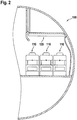
- Fig. 2 shows a schematic cross-sectional view through the passenger cabin 100 of the aircraft 1.
- Fig. 2 in particular shows a row of three passenger seats 110 and an overhead passenger service unit 120 installed above the passenger seats 110.
- the overhead passenger service unit 120 comprises the aircraft passenger lights in accordance with exemplary embodiments of the invention, as will be laid out below.
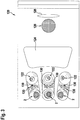
- Fig. 3 shows a more detailed schematic view of an overhead passenger service unit 120 from a position below the overhead passenger service unit 120.
- the overhead passenger service unit 120 comprises a row of three adjustable aircraft passenger lights (personal reading lights) 2, arranged next to each other in a lateral direction.
- Each of the aircraft passenger lights 2 may be embodied in accordance with any of the embodiments of aircraft passenger lights 2, described herein.
- Six electrical switches 130 are provided to the right side of the aircraft passenger lights 2, a pair of two switches 130 next to each of the aircraft passenger lights 2, respectively.
- One of the switches 130 of each pair may be configured for switching the adjacent aircraft passenger light 2, while the second switch of each pair may be configured for triggering a signal for calling cabin service personnel.
- the overhead passenger service unit 120 further comprises a loudspeaker 126, a display panel 128, and a covered cavity 124 for housing at least one oxygen mask (not shown).
- Fig. 4 depicts a schematic cross-sectional view of an aircraft passenger light 2 according to an exemplary embodiment of the invention.
- Fig. 5 depicts a schematic plan view of the aircraft passenger light 2 shown in Fig. 4 .
- the aircraft passenger light 2 comprises a basically circular outer wall 14 forming a nearly-cylindrical barrel, constituting part of a housing of the aircraft passenger light 2.
- a reflector 8 which in particular may be a parabolic reflector, is arranged within the housing, formed by the circular outer wall 14.
- the reflector 8 may have rotational symmetry and in particular is arranged coaxially with the circular outer wall 14 on a common axis A.
- the diameter d of the reflector 8 is smaller than the diameter D of the outer wall 14.
- the outer wall 14 is spaced apart from the reflector 8 in the radial direction, forming an interior space (“halo light chamber") 16 between an outer surface 8b of the reflector 8 and the outer wall 14.
- the diameters d, D of the reflector 8 and of the outer wall 14 may vary in the direction along the axis A, but the diameter d of the reflector 8 remains smaller than the diameter D of the outer wall 14.
- the variation of the diameters d, D of the reflector 8 and of the outer wall 14 in particular may result in a "banana like" cross-section of the halo light chamber 16, as it is schematically depicted in Fig. 4 .
- At least one reading light source 6 is provided within the reflector 8, in particular in an optical center of the reflector 8.
- the at least one reading light source 6 may be or may include at least one LED.
- the at least one reading light source 6 and the reflector 8 in combination constitute a reading light unit 4, configured for emitting a reading light output, which is basically centered around the axis A, when the at least one reading light source 6 is operated.
- the least one reading light source 6 may be configured for emitting white light, in particular white light having a correlated color temperature of at least 2500 K.
- the at least one reading light source 6 may be dimmable and/or it may comprise a plurality of reading light sources 6 which are individually switchable for varying the intensity of the light emitted by the reading light unit 4.
- the reflector 8 may be made of a reflective material, e.g. a metal.
- the inner side 8a of the reflector 8 may also be covered by a reflective coating, such as a metallic coating, for efficiently reflecting the light emitted by the at least one reading light source 6 in light emission directions E extending basically parallel to the axis A.
- a reflective coating such as a metallic coating
- At least one halo light source 12 is arranged in the halo light chamber 16, formed between the outer surface 8b of the reflector 8 and the outer wall 14.
- the at least one halo light source 12 and the at least one reading light source 6 in particular may be mounted to a common circuit board 10, in particular a printed circuit board, extending basically orthogonally to the axis A.
- the at least one reading light source 6 is arranged at or close to the center C of the reflector 8 / the axis A, and the at least one halo light source 12 is arranged at some radial distance a from the axis A within the halo light chamber 16, formed between the reflector 8 and the outer wall 14.
- the at least one halo light source 12 is configured for emitting the light into the halo light chamber 16 surrounding the reflector 8.
- the outer side 8b of the reflector 8 and/or the inner side 14a of the outer wall 14, facing the halo light chamber 16, may be reflective or diffusely reflective for reducing the amount of light absorbed by the reflector 8 and the outer wall 14, respectively.
- the reflector 8 and/or the outer wall 14 may be made of a reflective material, in particular a metallic material, or the outer side 8b of the reflector 8 and the inner side 14a of the outer wall 14 may be covered with a reflective coating, such as a metallic coating, respectively.
- the outer side 8b of the reflector 8 and/or the inner side 14a of the outer wall 14 may be white, or coated with a diffusely reflective coating, in particular a white coating.
- an at least partially transparent cover 18 is provided at an (outer) end of the halo light chamber 16 at the outer light emission side 2b of the aircraft passenger light 2.
- the at least partially transparent cover 18 is arranged opposite to the circuit board 10 with the at least one halo light source 12.
- another at least partially transparent cover 19 may extend over the outer side of the reflector 8.
- a single at least partially transparent cover (not shown) may cover both, the open outer side of the reflector 8 and the outer end of the halo light chamber 16.
- the cover(s) 18, 19 may be formed integrally with or separately from the reflector 8.
- an at least partially transparent cover may be part of or attached to the overhead passenger service unit 120 so that it is arranged in front of the aircraft passenger light 2.
- the at least partially transparent cover 19 may include a spreading disc causing a diffuse light output to be emitted from the halo light unit 5.
- a plurality of halo light sources 12 may be arranged at constant angular intervals, for example at angular intervals of 180°, 90° (as depicted in Fig. 5 ), 60°, 45°, 30° or 15°, along the circumference of the halo light chamber 16.
- a plurality of halo light sources 12 may be arranged at non-constant angular intervals along the circumference of the halo light chamber 16.
- the at least one halo light source 12 may be an LED or comprise a plurality of LEDs.
- the at least one halo light source 12 may be configured for emitting white light, in particular light having a correlated color temperature of at least 2500 K. Alternatively or additionally, the at least one halo light source 12 may be configured for emitting light having a different color, in particular, red, green, blue, yellow, purple or orange light.
- the halo light unit 5 may comprise a plurality of independently controllable halo light sources 12 which are configured for emitting light of different colors.
- the halo light unit 5 in particular may comprise at least three independently controllable halo light sources 12 of different colors, including at least one independently controllable red, green, and blue halo light source, respectively.
- Such a configuration allows the halo light unit to emit light having almost arbitrary colors by mixing the light emitted by the at least three halo light sources 12.
- Alternative combinations of light sources of different colors are also possible.
- the halo light unit 5 comprises a white light source, a red light source, a green light source, and a blue light source.
- the aircraft passenger light 2 may further comprise a controller 20 configured for controlling the at least one reading light source 6 and/or the at least one halo light source 12.
- the controller 20 may be configured for varying the intensity of light emitted by the reading light unit 4 by changing the number of activated reading light sources 6. Alternatively or additionally, the controller 20 may be configured for varying the intensity of light emitted by the reading light unit 4 by dimming the activated reading light source(s) 6.
- the controller 20 may be configured for varying the intensity of light emitted by the halo light unit 5 by changing the number of activated halo light sources 12. Alternatively or additionally, the controller 20 may be configured for varying the intensity of light emitted by the halo light unit 5 by dimming the activated halo light source(s) 12.
- the controller 20 may be configured for varying the color of the light emitted by the halo light unit 5 by selectively activating, deactivating and/or dimming the halo light sources 12 individually.
- controller 20 Although a single controller 20 is depicted in Fig. 4 , separate controllers for controlling the reading light sources 6 and the halo light sources 12 may be provided.
- the at least one reading light source 6 may be operated independently from the at least one halo light source 12. Operating the at least one reading light source 6 and operating the at least one halo light source 12 may include activating only a portion (subgroup) of a plurality of reading light sources 6 or halo light sources 12, respectively. Operating the at least one halo light source 12 may further include changing the color of the light emitted by the halo light unit 5 by selectively activating and/or deactivating and/or dimming different halo light sources 12 individually. The at least one halo light source 12 also may be operated in a flashing mode, in which the at least one halo light source 12 is repeatedly, in particular periodically, switched on and off.
- the at least one halo light source 12 may be activated simultaneously with or in advance of an acoustic announcement via the loudspeaker 126. Additionally, the at least one reading light source 6 may be dimmed simultaneously with or in advance of an acoustic announcement for increasing awareness of the passengers even further.
- the color of the light output emitted by the halo light unit 5 may be selected depending on a category and/or an occupancy status of a passenger seat 110 associated with the respective aircraft passenger light 2.
- different colors of the halo light output may be used for distinguishing between free and occupied/reserved passenger seats 110.
- Different colors of the halo light output may further be used for indicating different segments of the passenger cabin 100 associated with different booking classes. For example, a yellow ("gold") halo light output may indicate first class passenger seats 110, a red halo light output may indicate business class passenger seats 110, and a green halo light output may indicate economy class passenger seats 110.
- the colors of the halo light output may correspond with color codes printed on the tickets of the respective class.
- the color of the light output, emitted by the halo light unit 5, also may be used for indicating that a signal for calling cabin service personnel has been triggered.
Landscapes
- Engineering & Computer Science (AREA)
- Mechanical Engineering (AREA)
- Aviation & Aerospace Engineering (AREA)
- General Engineering & Computer Science (AREA)
- Non-Portable Lighting Devices Or Systems Thereof (AREA)
- Arrangements Of Lighting Devices For Vehicle Interiors, Mounting And Supporting Thereof, Circuits Therefore (AREA)
Abstract
Description
- The present invention is in the field of lighting devices. In particular, the present invention is in the field of lighting devices for aircraft and aircraft equipped with such lighting devices. Further in particular, the present invention is in the field of interior aircraft lighting systems.
- Modern aircraft comprise a variety of interior aircraft lights, including cabin illumination lights, aircraft passenger lights, exit sign lights, etc. An individually switchable aircraft passenger light ("reading light") is usually provided over and associated with each passenger seat.
- It would be beneficial to increase the application range of interior aircraft lighting systems.
- Exemplary embodiments of the invention include an aircraft passenger light, comprising a reading light unit and a halo light unit. The reading light unit comprises at least one reading light source and is configured for emitting a targeted reading light output. The halo light unit comprises at least one halo light source and is configured for emitting a ring-shaped halo light output, at least partly surrounding the targeted reading light output.
- The halo light unit adds additional functionality to the aircraft passenger light as it allows using the aircraft passenger light for additional purposes, in particular for indicating and signaling purposes, without occupying substantial additional space within the passenger cabin of the aircraft, in particular without dedicating an additional location within the passenger cabin of the aircraft to the additional functionality.
- The halo light unit may for example be used for indicating acoustic announcements and/or for providing information related to an associated passenger seat.
- According to a further embodiment, the halo light unit is configured for emitting a ring-shaped halo light output, completely surrounding the targeted reading light output. However, it is also possible that the halo light output only partly surrounds the targeted reading light output or surrounds the targeted reading light output in an interrupted manner, such as interrupted by mounting bars or strips, connecting the reading light unit, in particular a reflector thereof, to a housing of the aircraft passenger light on a light emission side of the aircraft passenger light. All of completely ring-shaped, partly ring-shaped or interrupted ring-shaped halo light outputs are encompassed by the terminology of the ring-shaped halo light output at least partly surrounding the targeted reading light output.
- According to a further embodiment, the reading light unit and the halo light unit have a common light emission plane, through which the targeted reading light output and the ring-shaped halo light output are emitted when the reading light unit and/or the halo light unit are operated. The reading light unit and the halo light unit may emit their respective light outputs in similar directions, in particular towards the associated passenger seat so that both light outputs are easily and reliably visible by a passenger sitting on said passenger seat. The reading light output may be more collimated than then halo light output. In other words, the opening angle of the reading light output may be more narrow than the opening angle of the halo light output. The halo light output in particular is not intended for illuminating of a target surface. While the reading light output may be exclusively targeted to the passenger's personal space, the halo light output may be visible from outside the passenger's personal space as well. For example, the halo light output may be visible for a passenger walking by the passenger seat associated with the aircraft passenger light in question.
- According to a further embodiment, the reading light unit and/or the halo light unit comprise a transparent cover for protecting the at least one reading light source and the at least one halo light source, respectively. The cover further protects the passenger from burning himself/herself by touching the potentially hot light sources and/or sensitive optical surfaces. Individual covers may be provided for the reading light unit and the halo light unit, respectively. Alternatively, a single cover, covering both the reading light unit and the halo light unit, may be provided.
- According to a further embodiment, the reading light unit comprises a reflector configured for directing the light output from the at least one reading light source towards the passenger seat. In this way, an efficient illumination of the area above the passenger seat may be achieved.
- The reflector may be rotationally symmetric with respect to a main light-emission axis of the reading light unit. The reflector may in particular a parabolic reflector. A parabolic reflector is easy to produce at low costs and allows for a very efficient illumination of the area above the passenger seat. The reflector may also be spherical or may be comprised of multiple spherical sections or may have any other suitable shape for concentrating the light from the at least one reading light source.
- According to a further embodiment, the reflector surrounds the at least one reading light source. Such a configuration results in an efficient reflection of the light, emitted by the at least one reading light source into various initial directions.
- According to a further embodiment, the at least one halo light source is arranged outside the reflector. Such a configuration allows for shaping the halo light output from the light emitted from the at least one halo light source independently of shaping the halo light output from the light emitted by the at least one reading light source. This adds additional flexibility to forming the total light output of the aircraft passenger light.
- According to a further embodiment, at least one of an inner surface and an outer surface of the reflector are reflective, in order to avoid absorbing considerable amounts of the light emitted by the at least one reading light source and the at least one halo light source, respectively.
- The reflector may be made of a reflective material, such as metal. The reflector also may be coated with a reflective coating, in particular with a metallic coating.
- According to a further embodiment, the aircraft passenger light comprises at least one outer wall arranged outside the reflector. In combination with the reflector, the outer wall in particular may form a halo light chamber between the outer surface of the reflector and the outer wall. The at least one halo light source may be arranged within said halo light chamber. Such a configuration allows for forming a ring-shaped halo light output around the reading light output. It further allows for shaping the halo light output by shaping the halo light chamber accordingly.
- According to a further embodiment, an inner side of the outer wall, facing the halo light chamber, is reflective or diffusely reflective, in order to avoid that a considerable amount of the light emitted by the at least one halo light source is absorbed by the outer wall. The inner side of the outer wall in particular may have a white color, or it may be coated with a reflective or diffusely reflective, in particular white, coating. The combination of a reflective outer surface of the reflector and a diffusely reflective, in particular white, inner side of the outer wall may provide for a particularly uniformly distributed and fairly wide angled halo light output, such that a pleasant appearance and an extended visibility of the halo light unit may be achieved.
- According to a further embodiment, the at least one reading light source and the at least one halo light source are arranged on a common circuit board, in particular on a common printed circuit board. Such a configuration results in a compact structure of the aircraft passenger light, which may be assembled easily at low costs as the number of parts to be assembled is small.
- According to a further embodiment, the at least one reading light source and/or the at least one halo light source is or comprises an LED. LEDs provide efficient and reliable light sources at low costs.
- According to a further embodiment, the at least one reading light source is configured for emitting white light, in particular white light having a correlated color temperature of more than 2500 K. White light is preferably used for reading lights.
- According to a further embodiment, the at least one halo light source is configured for emitting white light, in particular whitish light having a correlated color temperature of more than 2500 K, or light having a different color, in particular, red, green, blue, yellow, purple or orange light.
- According to a further embodiment, the halo light unit comprises a plurality of independently controllable halo light sources of different colors, particularly at least three independently controllable halo light sources of different colors, such as independently controllable red, green, and blue halo light sources. Such a configuration allows the halo light unit to emit light of almost arbitrary color by selectively activating one or more of the halo light sources, providing a large flexibility of the light emitted by the aircraft passenger light.
- Exemplary embodiments of the invention also include an aircraft comprising at least one aircraft passenger light according to any of the exemplary embodiments of the invention, as described above. Exemplary embodiments of the invention in particular include an aircraft comprising a passenger cabin and at least one aircraft passenger light according to an exemplary embodiment of the invention arranged within the passenger cabin. A plurality of passenger seats and aircraft passenger lights may be arranged within the passenger cabin. Each aircraft passenger light may be associated with one of the passenger seats, respectively; i.e. the reading light unit of each aircraft passenger light may be configured for illuminating a space above the associated passenger seat, in order to provide a personal reading light for a passenger sitting on the associated passenger seat. The additional features, modifications, and effects, described above with respect to the aircraft passenger light, apply to the aircraft in an analogous manner.
- Exemplary embodiments of the invention further include a method of operating an aircraft passenger light according to any of the exemplary embodiments of the invention, as described above, wherein the method comprises operating the at least one halo light source independently from the at least one reading light source. This allows using the halo light unit for indication purposes independently of the reading light source.
- Exemplary embodiments of the method in particular include selecting a color of the halo light output depending on a category and/or an occupancy status of the associated passenger seat and operating the at least one halo light source to emit the selected color. This allows passengers to recognize the category and/or the occupancy status of the passenger seats more easily, resulting in a safer and faster boarding of the passengers.
- For example, a yellow ("gold") halo light output may indicate first class seats, a red halo light output may indicate business class seats, and a green halo light output may indicate economy class seats. The colors of the halo light output may correspond with color codes printed on the tickets of the respective class.
- Alternatively, a green halo light output may indicate empty seats and a red halo light output may indicate occupied/reserved seats.
- According to a further embodiment, the at least one halo light source is operated in a flashing mode and/or the at least one halo light source is activated with or in advance of an acoustic announcement in the passenger cabin, in order to increase the awareness of the passengers to said announcement.
- Further exemplary embodiments of the invention will be described with respect to the accompanying drawings, wherein:
-
Fig. 1 schematically shows an aircraft with a passenger cabin, the aircraft being in accordance with an exemplary embodiment of the invention. -
Fig. 2 shows a schematic cross-sectional view through the passenger cabin of the aircraft ofFig. 1 . -
Fig. 3 shows an overhead passenger service unit, comprising aircraft passenger lights in accordance with exemplary embodiments of the invention, in a schematic view. -
Fig. 4 shows a schematic cross-sectional view of an aircraft passenger light according to an exemplary embodiment of the invention. -
Fig. 5 shows a schematic plan view of the aircraft passenger light shown inFig. 4 . -
Fig. 1 shows a schematic side view of an aircraft 1 with apassenger cabin 100. The aircraft 1 comprises a plurality of aircraft passenger lights in accordance with exemplary embodiments of the invention. The aircraft passenger lights are located in the interior of the passenger cabin and are thus not visible in the side view ofFig. 1 . -
Fig. 2 shows a schematic cross-sectional view through thepassenger cabin 100 of the aircraft 1.Fig. 2 in particular shows a row of threepassenger seats 110 and an overheadpassenger service unit 120 installed above the passenger seats 110. The overheadpassenger service unit 120 comprises the aircraft passenger lights in accordance with exemplary embodiments of the invention, as will be laid out below. -
Fig. 3 shows a more detailed schematic view of an overheadpassenger service unit 120 from a position below the overheadpassenger service unit 120. - On the side depicted to the left in
Fig. 3 , the overheadpassenger service unit 120 comprises a row of three adjustable aircraft passenger lights (personal reading lights) 2, arranged next to each other in a lateral direction. Each of theaircraft passenger lights 2 may be embodied in accordance with any of the embodiments ofaircraft passenger lights 2, described herein. - Six
electrical switches 130 are provided to the right side of theaircraft passenger lights 2, a pair of twoswitches 130 next to each of theaircraft passenger lights 2, respectively. One of theswitches 130 of each pair may be configured for switching the adjacentaircraft passenger light 2, while the second switch of each pair may be configured for triggering a signal for calling cabin service personnel. - A row of three
adjacent gaspers 122, arranged in the lateral direction, is provided next to theswitches 130. The overheadpassenger service unit 120 further comprises aloudspeaker 126, adisplay panel 128, and a coveredcavity 124 for housing at least one oxygen mask (not shown). -
Fig. 4 depicts a schematic cross-sectional view of anaircraft passenger light 2 according to an exemplary embodiment of the invention.Fig. 5 depicts a schematic plan view of theaircraft passenger light 2 shown inFig. 4 . - The
aircraft passenger light 2 comprises a basically circularouter wall 14 forming a nearly-cylindrical barrel, constituting part of a housing of theaircraft passenger light 2. - A
reflector 8, which in particular may be a parabolic reflector, is arranged within the housing, formed by the circularouter wall 14. Thereflector 8 may have rotational symmetry and in particular is arranged coaxially with the circularouter wall 14 on a common axis A. - In any virtual plane P oriented orthogonally to the axis A, the diameter d of the
reflector 8 is smaller than the diameter D of theouter wall 14. As a result, theouter wall 14 is spaced apart from thereflector 8 in the radial direction, forming an interior space ("halo light chamber") 16 between anouter surface 8b of thereflector 8 and theouter wall 14. - The diameters d, D of the
reflector 8 and of theouter wall 14 may vary in the direction along the axis A, but the diameter d of thereflector 8 remains smaller than the diameter D of theouter wall 14. The difference Δ = D - d between the diameter D of theouter wall 14 and the diameter d of thereflector 8 for example may be smaller at aninner side 2a of the aircraft passenger light 2 (shown at the bottom ofFig. 4 ) than at an opposing outer light emission side 2b (shown at the top ofFig. 4 ). - The variation of the diameters d, D of the
reflector 8 and of theouter wall 14 in particular may result in a "banana like" cross-section of the halolight chamber 16, as it is schematically depicted inFig. 4 . - At least one
reading light source 6 is provided within thereflector 8, in particular in an optical center of thereflector 8. The at least onereading light source 6 may be or may include at least one LED. - The at least one
reading light source 6 and thereflector 8 in combination constitute a reading light unit 4, configured for emitting a reading light output, which is basically centered around the axis A, when the at least onereading light source 6 is operated. - The least one
reading light source 6 may be configured for emitting white light, in particular white light having a correlated color temperature of at least 2500 K. - The at least one
reading light source 6 may be dimmable and/or it may comprise a plurality of readinglight sources 6 which are individually switchable for varying the intensity of the light emitted by the reading light unit 4. - An
inner side 8a of thereflector 8, facing the axis A, is reflective. Thereflector 8 may be made of a reflective material, e.g. a metal. - The
inner side 8a of thereflector 8 may also be covered by a reflective coating, such as a metallic coating, for efficiently reflecting the light emitted by the at least onereading light source 6 in light emission directions E extending basically parallel to the axis A. - At least one
halo light source 12 is arranged in the halolight chamber 16, formed between theouter surface 8b of thereflector 8 and theouter wall 14. - The at least one
halo light source 12 and the at least onereading light source 6 in particular may be mounted to acommon circuit board 10, in particular a printed circuit board, extending basically orthogonally to the axis A. In such a configuration, the at least onereading light source 6 is arranged at or close to the center C of thereflector 8 / the axis A, and the at least onehalo light source 12 is arranged at some radial distance a from the axis A within the halolight chamber 16, formed between thereflector 8 and theouter wall 14. - The at least one
halo light source 12 is configured for emitting the light into the halolight chamber 16 surrounding thereflector 8. - The
outer side 8b of thereflector 8 and/or theinner side 14a of theouter wall 14, facing the halolight chamber 16, may be reflective or diffusely reflective for reducing the amount of light absorbed by thereflector 8 and theouter wall 14, respectively. - The
reflector 8 and/or theouter wall 14 may be made of a reflective material, in particular a metallic material, or theouter side 8b of thereflector 8 and theinner side 14a of theouter wall 14 may be covered with a reflective coating, such as a metallic coating, respectively. - Alternatively, the
outer side 8b of thereflector 8 and/or theinner side 14a of theouter wall 14 may be white, or coated with a diffusely reflective coating, in particular a white coating. - For protecting the at least one
halo light source 12, an at least partiallytransparent cover 18 is provided at an (outer) end of the halolight chamber 16 at the outer light emission side 2b of theaircraft passenger light 2. The at least partiallytransparent cover 18 is arranged opposite to thecircuit board 10 with the at least onehalo light source 12. For protecting the at least onereading light source 6, another at least partiallytransparent cover 19 may extend over the outer side of thereflector 8. Alternatively, a single at least partially transparent cover (not shown) may cover both, the open outer side of thereflector 8 and the outer end of the halolight chamber 16. The cover(s) 18, 19 may be formed integrally with or separately from thereflector 8. As another alternative, an at least partially transparent cover (not shown) may be part of or attached to the overheadpassenger service unit 120 so that it is arranged in front of theaircraft passenger light 2. In any configuration, the at least partiallytransparent cover 19 may include a spreading disc causing a diffuse light output to be emitted from the halo light unit 5. - When viewed in a plan view, a plurality of halo
light sources 12 may be arranged at constant angular intervals, for example at angular intervals of 180°, 90° (as depicted inFig. 5 ), 60°, 45°, 30° or 15°, along the circumference of the halolight chamber 16. Alternatively, a plurality of halolight sources 12 may be arranged at non-constant angular intervals along the circumference of the halolight chamber 16. - The at least one
halo light source 12 may be an LED or comprise a plurality of LEDs. - The at least one
halo light source 12 may be configured for emitting white light, in particular light having a correlated color temperature of at least 2500 K. Alternatively or additionally, the at least onehalo light source 12 may be configured for emitting light having a different color, in particular, red, green, blue, yellow, purple or orange light. - The halo light unit 5 may comprise a plurality of independently controllable halo
light sources 12 which are configured for emitting light of different colors. The halo light unit 5 in particular may comprise at least three independently controllable halolight sources 12 of different colors, including at least one independently controllable red, green, and blue halo light source, respectively. Such a configuration allows the halo light unit to emit light having almost arbitrary colors by mixing the light emitted by the at least threehalo light sources 12. Alternative combinations of light sources of different colors are also possible. In particular, it is possible that the halo light unit 5 comprises a white light source, a red light source, a green light source, and a blue light source. - The
aircraft passenger light 2 may further comprise acontroller 20 configured for controlling the at least onereading light source 6 and/or the at least onehalo light source 12. - In case a plurality of reading
light sources 6 are provided, thecontroller 20 may be configured for varying the intensity of light emitted by the reading light unit 4 by changing the number of activated readinglight sources 6. Alternatively or additionally, thecontroller 20 may be configured for varying the intensity of light emitted by the reading light unit 4 by dimming the activated reading light source(s) 6. - In case a plurality of halo
light sources 12 are provided, thecontroller 20 may be configured for varying the intensity of light emitted by the halo light unit 5 by changing the number of activated halolight sources 12. Alternatively or additionally, thecontroller 20 may be configured for varying the intensity of light emitted by the halo light unit 5 by dimming the activated halo light source(s) 12. - In case a plurality of halo
light sources 12, configured for emitting light of different colors, is provided, thecontroller 20 may be configured for varying the color of the light emitted by the halo light unit 5 by selectively activating, deactivating and/or dimming thehalo light sources 12 individually. - Although a
single controller 20 is depicted inFig. 4 , separate controllers for controlling the readinglight sources 6 and thehalo light sources 12 may be provided. - The at least one
reading light source 6 may be operated independently from the at least onehalo light source 12. Operating the at least onereading light source 6 and operating the at least onehalo light source 12 may include activating only a portion (subgroup) of a plurality of readinglight sources 6 or halolight sources 12, respectively. Operating the at least onehalo light source 12 may further include changing the color of the light emitted by the halo light unit 5 by selectively activating and/or deactivating and/or dimming different halolight sources 12 individually. The at least onehalo light source 12 also may be operated in a flashing mode, in which the at least onehalo light source 12 is repeatedly, in particular periodically, switched on and off. - For increasing awareness of the passengers, the at least one
halo light source 12 may be activated simultaneously with or in advance of an acoustic announcement via theloudspeaker 126. Additionally, the at least onereading light source 6 may be dimmed simultaneously with or in advance of an acoustic announcement for increasing awareness of the passengers even further. - The color of the light output emitted by the halo light unit 5 may be selected depending on a category and/or an occupancy status of a
passenger seat 110 associated with the respectiveaircraft passenger light 2. - In particular, different colors of the halo light output may be used for distinguishing between free and occupied/reserved passenger seats 110.
- Different colors of the halo light output may further be used for indicating different segments of the
passenger cabin 100 associated with different booking classes. For example, a yellow ("gold") halo light output may indicate firstclass passenger seats 110, a red halo light output may indicate businessclass passenger seats 110, and a green halo light output may indicate economy class passenger seats 110. The colors of the halo light output may correspond with color codes printed on the tickets of the respective class. - The color of the light output, emitted by the halo light unit 5, also may be used for indicating that a signal for calling cabin service personnel has been triggered.
- While the invention has been described with reference to exemplary embodiments, it will be understood by those skilled in the art that various changes may be made and equivalents may be substituted for elements thereof without departing from the scope of the invention. In addition, many modifications may be made to adapt a particular situation or material to the teachings of the invention without departing from the essential scope thereof. Therefore, it is intended that the invention not be limited to the particular embodiment disclosed, but that the invention will include all embodiments falling within the scope of the appended claims.
Claims (15)
- An aircraft passenger light (2) including:a reading light unit (4), comprising at least one reading light source (6) and configured for emitting a targeted reading light output; anda halo light unit (5), comprising at least one halo light source (12) and configured for emitting a ring-shaped halo light output, at least partly surrounding the targeted reading light output.
- The aircraft passenger light (2) according to claim 1, wherein the reading light unit (4) and the halo light unit (5) have a common light emission plane, through which the targeted reading light output and the ring-shaped halo light output are emitted in operation.
- The aircraft passenger light (2) according to claim 1 or 2, wherein the reading light unit (4) and/or the halo light unit (5) comprise a transparent cover (18, 19).
- The aircraft passenger light (2) according to any of the preceding claims, wherein the reading light unit (4) comprises a reflector (8), wherein the reflector (8) in particular is rotationally symmetric with respect to a main light emission axis (A) of the reading light unit (4), wherein the reflector (8) more particularly is a parabolic reflector (8).
- The aircraft passenger light (2) according to claim 4, wherein the reflector (8) surrounds the at least one reading light source (6) and wherein the at least one halo light source (12) is arranged outside the reflector (8).
- The aircraft passenger light (2) according to any of claims 4 or 5, wherein an inner surface (8a) as well as an outer surface (8b) of the reflector (8) are reflective, respectively.
- The aircraft passenger light (2) according to any of claims 4 to 6, comprising at least one outer wall (14) arranged outside the reflector (8), thereby forming a halo light chamber (16) between the outer surface of the reflector (8) and the outer wall (14), wherein the at least one halo light source (12) is arranged within said halo light chamber (16).
- The aircraft passenger light (2) according to claim 7, wherein an inner side (14a) of the outer wall (14), facing the halo light chamber (16), is reflective or diffusely reflective.
- The aircraft passenger light (2) according to any of the preceding claims, wherein the at least one reading light source (6) and the at least one halo light source (12) are arranged on a common circuit board (10), in particular on a common printed circuit board (10).
- The aircraft passenger light (2) according to any of the preceding claims,
wherein the at least one reading light source (6) is an LED and/or is configured for emitting white light,
and/or
wherein the at least one halo light source (12) is an LED and/or is configured for emitting white light or light having a different color, in particular, red, green, blue, yellow, purple or orange light. - The aircraft passenger light (2) according to any of the preceding claims, wherein the halo light unit (5) comprises a plurality of independently controllable halo light sources (12) of different colors, in particular at least three independently controllable halo light sources (12) of different colors, such as independently controllable red, green, and blue halo light sources (12).
- Aircraft (1) comprising at least one aircraft passenger light (2) according to any of the preceding claims.
- Method of operating an aircraft passenger light (2) according to any of the preceding claims, comprising:
operating the at least one halo light source (12) independently from the at least one reading light source (6). - Method according to claim 13, comprising:selecting a color of the halo light output depending on a category and/or an occupancy status of a passenger seat (110) associated with the aircraft passenger light (2), andoperating the at least one halo light source (12) to emit the selected color.
- Method according to claim 13 or 14, comprising:
operating the at least one halo light source (12) in a flashing mode and/or activating the at least one halo light source (12) simultaneously with or in advance of an acoustic announcement.
Priority Applications (3)
| Application Number | Priority Date | Filing Date | Title |
|---|---|---|---|
| EP22217177.9A EP4177108B1 (en) | 2019-07-12 | 2019-07-12 | Aircraft passenger light |
| EP19186071.7A EP3763569B1 (en) | 2019-07-12 | 2019-07-12 | Aircraft passenger light |
| US16/711,881 US10967785B2 (en) | 2019-07-12 | 2019-12-12 | Aircraft passenger light with reading and halo lighting |
Applications Claiming Priority (1)
| Application Number | Priority Date | Filing Date | Title |
|---|---|---|---|
| EP19186071.7A EP3763569B1 (en) | 2019-07-12 | 2019-07-12 | Aircraft passenger light |
Related Child Applications (1)
| Application Number | Title | Priority Date | Filing Date |
|---|---|---|---|
| EP22217177.9A Division EP4177108B1 (en) | 2019-07-12 | 2019-07-12 | Aircraft passenger light |
Publications (2)
| Publication Number | Publication Date |
|---|---|
| EP3763569A1 true EP3763569A1 (en) | 2021-01-13 |
| EP3763569B1 EP3763569B1 (en) | 2023-01-04 |
Family
ID=67262187
Family Applications (2)
| Application Number | Title | Priority Date | Filing Date |
|---|---|---|---|
| EP19186071.7A Active EP3763569B1 (en) | 2019-07-12 | 2019-07-12 | Aircraft passenger light |
| EP22217177.9A Active EP4177108B1 (en) | 2019-07-12 | 2019-07-12 | Aircraft passenger light |
Family Applications After (1)
| Application Number | Title | Priority Date | Filing Date |
|---|---|---|---|
| EP22217177.9A Active EP4177108B1 (en) | 2019-07-12 | 2019-07-12 | Aircraft passenger light |
Country Status (2)
| Country | Link |
|---|---|
| US (1) | US10967785B2 (en) |
| EP (2) | EP3763569B1 (en) |
Cited By (2)
| Publication number | Priority date | Publication date | Assignee | Title |
|---|---|---|---|---|
| DE102021211798A1 (en) | 2021-10-19 | 2023-04-20 | Glp German Light Products Gmbh | LIGHTING BODY |
| EP4349711A1 (en) * | 2022-10-05 | 2024-04-10 | Goodrich Lighting Systems GmbH & Co. KG | Aircraft reading light, aircraft comprising an aircraft reading light, and method of operating an aircraft reading light |
Families Citing this family (1)
| Publication number | Priority date | Publication date | Assignee | Title |
|---|---|---|---|---|
| EP4650273A1 (en) * | 2024-05-14 | 2025-11-19 | Goodrich Lighting Systems GmbH & Co. KG | Aircraft passenger reading light, aircraft comprising an aircraft passenger reading light, and method of operating an aircraft passenger reading light |
Citations (5)
| Publication number | Priority date | Publication date | Assignee | Title |
|---|---|---|---|---|
| EP1043542A2 (en) * | 1999-04-07 | 2000-10-11 | Zumtobel Staff GmbH | Lighting system for mounting to a room ceiling or wall |
| JP2007134067A (en) * | 2005-11-08 | 2007-05-31 | Koito Mfg Co Ltd | Interior lighting |
| DE102010014839A1 (en) * | 2010-02-11 | 2011-08-11 | Frensch GmbH, 47229 | recessed light |
| FR3062893A1 (en) * | 2017-02-16 | 2018-08-17 | G. Cartier Technologies | OPTICAL DEVICE FOR LIGHTING AND SIGNALING |
| DE102017215892A1 (en) * | 2017-09-08 | 2019-03-14 | Volkswagen Aktiengesellschaft | Lighting device for a vehicle |
Family Cites Families (6)
| Publication number | Priority date | Publication date | Assignee | Title |
|---|---|---|---|---|
| DE102008029511A1 (en) * | 2008-06-21 | 2010-02-11 | Airbus Deutschland Gmbh | Reading or spot light |
| US9045235B2 (en) | 2013-07-31 | 2015-06-02 | Zodiac Aerotechnics | Service device, passenger service unit, fuselage of an aircraft, method for installing the service device |
| US9487296B2 (en) | 2013-09-30 | 2016-11-08 | Peco Manufacturing Co., Inc. | Passenger service unit and related systems |
| EP3114903B1 (en) | 2014-02-28 | 2018-07-18 | Bombardier Inc. | Method, system, and executable program product for controlling lighting |
| EP2915699A3 (en) | 2014-03-07 | 2016-04-20 | IDD Aerospace Corporation | Aircraft cabin light systems |
| US10506339B2 (en) | 2014-09-29 | 2019-12-10 | B/E Aerospace, Inc. | Smart passenger service unit |
-
2019
- 2019-07-12 EP EP19186071.7A patent/EP3763569B1/en active Active
- 2019-07-12 EP EP22217177.9A patent/EP4177108B1/en active Active
- 2019-12-12 US US16/711,881 patent/US10967785B2/en active Active
Patent Citations (5)
| Publication number | Priority date | Publication date | Assignee | Title |
|---|---|---|---|---|
| EP1043542A2 (en) * | 1999-04-07 | 2000-10-11 | Zumtobel Staff GmbH | Lighting system for mounting to a room ceiling or wall |
| JP2007134067A (en) * | 2005-11-08 | 2007-05-31 | Koito Mfg Co Ltd | Interior lighting |
| DE102010014839A1 (en) * | 2010-02-11 | 2011-08-11 | Frensch GmbH, 47229 | recessed light |
| FR3062893A1 (en) * | 2017-02-16 | 2018-08-17 | G. Cartier Technologies | OPTICAL DEVICE FOR LIGHTING AND SIGNALING |
| DE102017215892A1 (en) * | 2017-09-08 | 2019-03-14 | Volkswagen Aktiengesellschaft | Lighting device for a vehicle |
Cited By (4)
| Publication number | Priority date | Publication date | Assignee | Title |
|---|---|---|---|---|
| DE102021211798A1 (en) | 2021-10-19 | 2023-04-20 | Glp German Light Products Gmbh | LIGHTING BODY |
| US12578072B2 (en) | 2021-10-19 | 2026-03-17 | Glp German Light Products Gmbh | Illumination body |
| EP4349711A1 (en) * | 2022-10-05 | 2024-04-10 | Goodrich Lighting Systems GmbH & Co. KG | Aircraft reading light, aircraft comprising an aircraft reading light, and method of operating an aircraft reading light |
| US12123591B2 (en) | 2022-10-05 | 2024-10-22 | Goodrich Lighting Systems GmbH & Co. KG | Aircraft reading light, aircraft comprising an aircraft reading light, and method of operating an aircraft reading light |
Also Published As
| Publication number | Publication date |
|---|---|
| US10967785B2 (en) | 2021-04-06 |
| US20210009033A1 (en) | 2021-01-14 |
| EP4177108A1 (en) | 2023-05-10 |
| EP4177108B1 (en) | 2026-04-15 |
| EP3763569B1 (en) | 2023-01-04 |
Similar Documents
| Publication | Publication Date | Title |
|---|---|---|
| US10967785B2 (en) | Aircraft passenger light with reading and halo lighting | |
| US6450661B1 (en) | Light source device using light emitting diode and light emitting device using same | |
| CA2606635C (en) | Installation light | |
| US7566154B2 (en) | Aircraft LED dome light having rotatably releasable housing mounted within mounting flange | |
| US4680678A (en) | Lighting fixture for vehicle | |
| US10458617B2 (en) | Light device, especially a signal lamp for motor vehicles | |
| CA2114397A1 (en) | Indicating element for elevators | |
| US11293611B2 (en) | Exterior helicopter light | |
| US20170167688A1 (en) | Light device, especially a signal lamp for motor vehicles | |
| ES2350342T3 (en) | MULTIFUNCTION EDGE DEVICE FOR AUTOMATIC DOORS. | |
| US10701772B2 (en) | Lighting device with variable light distribution | |
| US8021028B2 (en) | Vehicle light | |
| JP2020502744A (en) | LED lighting module with fixed optics and variable emission pattern | |
| CZ2015588A3 (en) | A lighting device, particularly a signalling lamp for motor vehicles | |
| EP3738877B1 (en) | Interior aircraft light, aircraft cabin lighting system, aircraft, and method of illuminating an aircraft cabin | |
| CN205602142U (en) | passenger service device | |
| US8322880B2 (en) | Illumination device for an aircraft | |
| EP4242060B1 (en) | Aircraft passenger reading light | |
| US20080013332A1 (en) | Invisible Emergency Lighting for an Aircraft Cabin | |
| US12123591B2 (en) | Aircraft reading light, aircraft comprising an aircraft reading light, and method of operating an aircraft reading light | |
| US20230348097A1 (en) | Aircraft passenger cabin light, aircraft passenger cabin lighting system, and method of installing an aircraft passenger cabin lighting system | |
| CN109466435B (en) | Lighting device for vehicle | |
| WO2011029998A1 (en) | Illuminated sign and illuminated sign system | |
| ES2235561B1 (en) | PILOT LIGHT FOR VEHICLES. | |
| JP2006147332A (en) | Lighting device |
Legal Events
| Date | Code | Title | Description |
|---|---|---|---|
| PUAI | Public reference made under article 153(3) epc to a published international application that has entered the european phase |
Free format text: ORIGINAL CODE: 0009012 |
|
| STAA | Information on the status of an ep patent application or granted ep patent |
Free format text: STATUS: THE APPLICATION HAS BEEN PUBLISHED |
|
| AK | Designated contracting states |
Kind code of ref document: A1 Designated state(s): AL AT BE BG CH CY CZ DE DK EE ES FI FR GB GR HR HU IE IS IT LI LT LU LV MC MK MT NL NO PL PT RO RS SE SI SK SM TR |
|
| AX | Request for extension of the european patent |
Extension state: BA ME |
|
| STAA | Information on the status of an ep patent application or granted ep patent |
Free format text: STATUS: REQUEST FOR EXAMINATION WAS MADE |
|
| 17P | Request for examination filed |
Effective date: 20210712 |
|
| RBV | Designated contracting states (corrected) |
Designated state(s): AL AT BE BG CH CY CZ DE DK EE ES FI FR GB GR HR HU IE IS IT LI LT LU LV MC MK MT NL NO PL PT RO RS SE SI SK SM TR |
|
| RIC1 | Information provided on ipc code assigned before grant |
Ipc: F21Y 115/10 20160101ALN20220530BHEP Ipc: B64D 11/00 20060101ALI20220530BHEP Ipc: B60Q 3/47 20170101ALI20220530BHEP Ipc: B60Q 3/60 20170101ALI20220530BHEP Ipc: B60Q 3/44 20170101AFI20220530BHEP |
|
| GRAP | Despatch of communication of intention to grant a patent |
Free format text: ORIGINAL CODE: EPIDOSNIGR1 |
|
| STAA | Information on the status of an ep patent application or granted ep patent |
Free format text: STATUS: GRANT OF PATENT IS INTENDED |
|
| INTG | Intention to grant announced |
Effective date: 20220708 |
|
| RIC1 | Information provided on ipc code assigned before grant |
Ipc: F21Y 115/10 20160101ALN20220629BHEP Ipc: B64D 11/00 20060101ALI20220629BHEP Ipc: B60Q 3/47 20170101ALI20220629BHEP Ipc: B60Q 3/60 20170101ALI20220629BHEP Ipc: B60Q 3/44 20170101AFI20220629BHEP |
|
| GRAS | Grant fee paid |
Free format text: ORIGINAL CODE: EPIDOSNIGR3 |
|
| GRAA | (expected) grant |
Free format text: ORIGINAL CODE: 0009210 |
|
| STAA | Information on the status of an ep patent application or granted ep patent |
Free format text: STATUS: THE PATENT HAS BEEN GRANTED |
|
| AK | Designated contracting states |
Kind code of ref document: B1 Designated state(s): AL AT BE BG CH CY CZ DE DK EE ES FI FR GB GR HR HU IE IS IT LI LT LU LV MC MK MT NL NO PL PT RO RS SE SI SK SM TR |
|
| REG | Reference to a national code |
Ref country code: GB Ref legal event code: FG4D |
|
| REG | Reference to a national code |
Ref country code: CH Ref legal event code: EP |
|
| REG | Reference to a national code |
Ref country code: AT Ref legal event code: REF Ref document number: 1541719 Country of ref document: AT Kind code of ref document: T Effective date: 20230115 |
|
| REG | Reference to a national code |
Ref country code: DE Ref legal event code: R096 Ref document number: 602019023878 Country of ref document: DE |
|
| REG | Reference to a national code |
Ref country code: IE Ref legal event code: FG4D |
|
| REG | Reference to a national code |
Ref country code: LT Ref legal event code: MG9D |
|
| REG | Reference to a national code |
Ref country code: NL Ref legal event code: MP Effective date: 20230104 |
|
| REG | Reference to a national code |
Ref country code: AT Ref legal event code: MK05 Ref document number: 1541719 Country of ref document: AT Kind code of ref document: T Effective date: 20230104 |
|
| PG25 | Lapsed in a contracting state [announced via postgrant information from national office to epo] |
Ref country code: NL Free format text: LAPSE BECAUSE OF FAILURE TO SUBMIT A TRANSLATION OF THE DESCRIPTION OR TO PAY THE FEE WITHIN THE PRESCRIBED TIME-LIMIT Effective date: 20230104 |
|
| PG25 | Lapsed in a contracting state [announced via postgrant information from national office to epo] |
Ref country code: RS Free format text: LAPSE BECAUSE OF FAILURE TO SUBMIT A TRANSLATION OF THE DESCRIPTION OR TO PAY THE FEE WITHIN THE PRESCRIBED TIME-LIMIT Effective date: 20230104 Ref country code: PT Free format text: LAPSE BECAUSE OF FAILURE TO SUBMIT A TRANSLATION OF THE DESCRIPTION OR TO PAY THE FEE WITHIN THE PRESCRIBED TIME-LIMIT Effective date: 20230504 Ref country code: NO Free format text: LAPSE BECAUSE OF FAILURE TO SUBMIT A TRANSLATION OF THE DESCRIPTION OR TO PAY THE FEE WITHIN THE PRESCRIBED TIME-LIMIT Effective date: 20230404 Ref country code: LV Free format text: LAPSE BECAUSE OF FAILURE TO SUBMIT A TRANSLATION OF THE DESCRIPTION OR TO PAY THE FEE WITHIN THE PRESCRIBED TIME-LIMIT Effective date: 20230104 Ref country code: LT Free format text: LAPSE BECAUSE OF FAILURE TO SUBMIT A TRANSLATION OF THE DESCRIPTION OR TO PAY THE FEE WITHIN THE PRESCRIBED TIME-LIMIT Effective date: 20230104 Ref country code: HR Free format text: LAPSE BECAUSE OF FAILURE TO SUBMIT A TRANSLATION OF THE DESCRIPTION OR TO PAY THE FEE WITHIN THE PRESCRIBED TIME-LIMIT Effective date: 20230104 Ref country code: ES Free format text: LAPSE BECAUSE OF FAILURE TO SUBMIT A TRANSLATION OF THE DESCRIPTION OR TO PAY THE FEE WITHIN THE PRESCRIBED TIME-LIMIT Effective date: 20230104 Ref country code: AT Free format text: LAPSE BECAUSE OF FAILURE TO SUBMIT A TRANSLATION OF THE DESCRIPTION OR TO PAY THE FEE WITHIN THE PRESCRIBED TIME-LIMIT Effective date: 20230104 |
|
| P01 | Opt-out of the competence of the unified patent court (upc) registered |
Effective date: 20230630 |
|
| PG25 | Lapsed in a contracting state [announced via postgrant information from national office to epo] |
Ref country code: SE Free format text: LAPSE BECAUSE OF FAILURE TO SUBMIT A TRANSLATION OF THE DESCRIPTION OR TO PAY THE FEE WITHIN THE PRESCRIBED TIME-LIMIT Effective date: 20230104 Ref country code: PL Free format text: LAPSE BECAUSE OF FAILURE TO SUBMIT A TRANSLATION OF THE DESCRIPTION OR TO PAY THE FEE WITHIN THE PRESCRIBED TIME-LIMIT Effective date: 20230104 Ref country code: IS Free format text: LAPSE BECAUSE OF FAILURE TO SUBMIT A TRANSLATION OF THE DESCRIPTION OR TO PAY THE FEE WITHIN THE PRESCRIBED TIME-LIMIT Effective date: 20230504 Ref country code: GR Free format text: LAPSE BECAUSE OF FAILURE TO SUBMIT A TRANSLATION OF THE DESCRIPTION OR TO PAY THE FEE WITHIN THE PRESCRIBED TIME-LIMIT Effective date: 20230405 Ref country code: FI Free format text: LAPSE BECAUSE OF FAILURE TO SUBMIT A TRANSLATION OF THE DESCRIPTION OR TO PAY THE FEE WITHIN THE PRESCRIBED TIME-LIMIT Effective date: 20230104 |
|
| REG | Reference to a national code |
Ref country code: DE Ref legal event code: R097 Ref document number: 602019023878 Country of ref document: DE |
|
| PG25 | Lapsed in a contracting state [announced via postgrant information from national office to epo] |
Ref country code: SM Free format text: LAPSE BECAUSE OF FAILURE TO SUBMIT A TRANSLATION OF THE DESCRIPTION OR TO PAY THE FEE WITHIN THE PRESCRIBED TIME-LIMIT Effective date: 20230104 Ref country code: RO Free format text: LAPSE BECAUSE OF FAILURE TO SUBMIT A TRANSLATION OF THE DESCRIPTION OR TO PAY THE FEE WITHIN THE PRESCRIBED TIME-LIMIT Effective date: 20230104 Ref country code: EE Free format text: LAPSE BECAUSE OF FAILURE TO SUBMIT A TRANSLATION OF THE DESCRIPTION OR TO PAY THE FEE WITHIN THE PRESCRIBED TIME-LIMIT Effective date: 20230104 Ref country code: DK Free format text: LAPSE BECAUSE OF FAILURE TO SUBMIT A TRANSLATION OF THE DESCRIPTION OR TO PAY THE FEE WITHIN THE PRESCRIBED TIME-LIMIT Effective date: 20230104 Ref country code: CZ Free format text: LAPSE BECAUSE OF FAILURE TO SUBMIT A TRANSLATION OF THE DESCRIPTION OR TO PAY THE FEE WITHIN THE PRESCRIBED TIME-LIMIT Effective date: 20230104 |
|
| PLBE | No opposition filed within time limit |
Free format text: ORIGINAL CODE: 0009261 |
|
| STAA | Information on the status of an ep patent application or granted ep patent |
Free format text: STATUS: NO OPPOSITION FILED WITHIN TIME LIMIT |
|
| PG25 | Lapsed in a contracting state [announced via postgrant information from national office to epo] |
Ref country code: SK Free format text: LAPSE BECAUSE OF FAILURE TO SUBMIT A TRANSLATION OF THE DESCRIPTION OR TO PAY THE FEE WITHIN THE PRESCRIBED TIME-LIMIT Effective date: 20230104 |
|
| 26N | No opposition filed |
Effective date: 20231005 |
|
| PG25 | Lapsed in a contracting state [announced via postgrant information from national office to epo] |
Ref country code: SI Free format text: LAPSE BECAUSE OF FAILURE TO SUBMIT A TRANSLATION OF THE DESCRIPTION OR TO PAY THE FEE WITHIN THE PRESCRIBED TIME-LIMIT Effective date: 20230104 |
|
| PG25 | Lapsed in a contracting state [announced via postgrant information from national office to epo] |
Ref country code: MC Free format text: LAPSE BECAUSE OF FAILURE TO SUBMIT A TRANSLATION OF THE DESCRIPTION OR TO PAY THE FEE WITHIN THE PRESCRIBED TIME-LIMIT Effective date: 20230104 |
|
| PG25 | Lapsed in a contracting state [announced via postgrant information from national office to epo] |
Ref country code: MC Free format text: LAPSE BECAUSE OF FAILURE TO SUBMIT A TRANSLATION OF THE DESCRIPTION OR TO PAY THE FEE WITHIN THE PRESCRIBED TIME-LIMIT Effective date: 20230104 |
|
| REG | Reference to a national code |
Ref country code: CH Ref legal event code: PL |
|
| REG | Reference to a national code |
Ref country code: BE Ref legal event code: MM Effective date: 20230731 |
|
| PG25 | Lapsed in a contracting state [announced via postgrant information from national office to epo] |
Ref country code: LU Free format text: LAPSE BECAUSE OF NON-PAYMENT OF DUE FEES Effective date: 20230712 |
|
| PG25 | Lapsed in a contracting state [announced via postgrant information from national office to epo] |
Ref country code: LU Free format text: LAPSE BECAUSE OF NON-PAYMENT OF DUE FEES Effective date: 20230712 |
|
| REG | Reference to a national code |
Ref country code: IE Ref legal event code: MM4A |
|
| PG25 | Lapsed in a contracting state [announced via postgrant information from national office to epo] |
Ref country code: CH Free format text: LAPSE BECAUSE OF NON-PAYMENT OF DUE FEES Effective date: 20230731 |
|
| PG25 | Lapsed in a contracting state [announced via postgrant information from national office to epo] |
Ref country code: IT Free format text: LAPSE BECAUSE OF FAILURE TO SUBMIT A TRANSLATION OF THE DESCRIPTION OR TO PAY THE FEE WITHIN THE PRESCRIBED TIME-LIMIT Effective date: 20230104 Ref country code: BE Free format text: LAPSE BECAUSE OF NON-PAYMENT OF DUE FEES Effective date: 20230731 |
|
| PG25 | Lapsed in a contracting state [announced via postgrant information from national office to epo] |
Ref country code: IE Free format text: LAPSE BECAUSE OF NON-PAYMENT OF DUE FEES Effective date: 20230712 |
|
| PG25 | Lapsed in a contracting state [announced via postgrant information from national office to epo] |
Ref country code: IE Free format text: LAPSE BECAUSE OF NON-PAYMENT OF DUE FEES Effective date: 20230712 |
|
| PG25 | Lapsed in a contracting state [announced via postgrant information from national office to epo] |
Ref country code: BG Free format text: LAPSE BECAUSE OF FAILURE TO SUBMIT A TRANSLATION OF THE DESCRIPTION OR TO PAY THE FEE WITHIN THE PRESCRIBED TIME-LIMIT Effective date: 20230104 |
|
| PG25 | Lapsed in a contracting state [announced via postgrant information from national office to epo] |
Ref country code: BG Free format text: LAPSE BECAUSE OF FAILURE TO SUBMIT A TRANSLATION OF THE DESCRIPTION OR TO PAY THE FEE WITHIN THE PRESCRIBED TIME-LIMIT Effective date: 20230104 |
|
| PGFP | Annual fee paid to national office [announced via postgrant information from national office to epo] |
Ref country code: GB Payment date: 20250619 Year of fee payment: 7 |
|
| PGFP | Annual fee paid to national office [announced via postgrant information from national office to epo] |
Ref country code: FR Payment date: 20250619 Year of fee payment: 7 |
|
| PG25 | Lapsed in a contracting state [announced via postgrant information from national office to epo] |
Ref country code: CY Free format text: LAPSE BECAUSE OF FAILURE TO SUBMIT A TRANSLATION OF THE DESCRIPTION OR TO PAY THE FEE WITHIN THE PRESCRIBED TIME-LIMIT; INVALID AB INITIO Effective date: 20190712 |
|
| PG25 | Lapsed in a contracting state [announced via postgrant information from national office to epo] |
Ref country code: HU Free format text: LAPSE BECAUSE OF FAILURE TO SUBMIT A TRANSLATION OF THE DESCRIPTION OR TO PAY THE FEE WITHIN THE PRESCRIBED TIME-LIMIT; INVALID AB INITIO Effective date: 20190712 |
|
| PGFP | Annual fee paid to national office [announced via postgrant information from national office to epo] |
Ref country code: DE Payment date: 20250620 Year of fee payment: 7 |
|
| PG25 | Lapsed in a contracting state [announced via postgrant information from national office to epo] |
Ref country code: TR Free format text: LAPSE BECAUSE OF FAILURE TO SUBMIT A TRANSLATION OF THE DESCRIPTION OR TO PAY THE FEE WITHIN THE PRESCRIBED TIME-LIMIT Effective date: 20230104 |