EP3763500A1 - Kneading rotor and batch-type kneading machine - Google Patents
Kneading rotor and batch-type kneading machine Download PDFInfo
- Publication number
- EP3763500A1 EP3763500A1 EP19784713.0A EP19784713A EP3763500A1 EP 3763500 A1 EP3763500 A1 EP 3763500A1 EP 19784713 A EP19784713 A EP 19784713A EP 3763500 A1 EP3763500 A1 EP 3763500A1
- Authority
- EP
- European Patent Office
- Prior art keywords
- kneading
- wings
- rotor
- long
- wing
- Prior art date
- Legal status (The legal status is an assumption and is not a legal conclusion. Google has not performed a legal analysis and makes no representation as to the accuracy of the status listed.)
- Granted
Links
Images







Classifications
-
- B—PERFORMING OPERATIONS; TRANSPORTING
- B01—PHYSICAL OR CHEMICAL PROCESSES OR APPARATUS IN GENERAL
- B01F—MIXING, e.g. DISSOLVING, EMULSIFYING OR DISPERSING
- B01F27/00—Mixers with rotary stirring devices in fixed receptacles; Kneaders
- B01F27/80—Mixers with rotary stirring devices in fixed receptacles; Kneaders with stirrers rotating about a substantially vertical axis
- B01F27/90—Mixers with rotary stirring devices in fixed receptacles; Kneaders with stirrers rotating about a substantially vertical axis with paddles or arms
-
- B—PERFORMING OPERATIONS; TRANSPORTING
- B01—PHYSICAL OR CHEMICAL PROCESSES OR APPARATUS IN GENERAL
- B01F—MIXING, e.g. DISSOLVING, EMULSIFYING OR DISPERSING
- B01F27/00—Mixers with rotary stirring devices in fixed receptacles; Kneaders
- B01F27/80—Mixers with rotary stirring devices in fixed receptacles; Kneaders with stirrers rotating about a substantially vertical axis
- B01F27/92—Mixers with rotary stirring devices in fixed receptacles; Kneaders with stirrers rotating about a substantially vertical axis with helices or screws
-
- B—PERFORMING OPERATIONS; TRANSPORTING
- B29—WORKING OF PLASTICS; WORKING OF SUBSTANCES IN A PLASTIC STATE IN GENERAL
- B29B—PREPARATION OR PRETREATMENT OF THE MATERIAL TO BE SHAPED; MAKING GRANULES OR PREFORMS; RECOVERY OF PLASTICS OR OTHER CONSTITUENTS OF WASTE MATERIAL CONTAINING PLASTICS
- B29B7/00—Mixing; Kneading
- B29B7/02—Mixing; Kneading non-continuous, with mechanical mixing or kneading devices, i.e. batch type
- B29B7/06—Mixing; Kneading non-continuous, with mechanical mixing or kneading devices, i.e. batch type with movable mixing or kneading devices
- B29B7/10—Mixing; Kneading non-continuous, with mechanical mixing or kneading devices, i.e. batch type with movable mixing or kneading devices rotary
- B29B7/18—Mixing; Kneading non-continuous, with mechanical mixing or kneading devices, i.e. batch type with movable mixing or kneading devices rotary with more than one shaft
- B29B7/183—Mixing; Kneading non-continuous, with mechanical mixing or kneading devices, i.e. batch type with movable mixing or kneading devices rotary with more than one shaft having a casing closely surrounding the rotors, e.g. of Banbury type
-
- B—PERFORMING OPERATIONS; TRANSPORTING
- B29—WORKING OF PLASTICS; WORKING OF SUBSTANCES IN A PLASTIC STATE IN GENERAL
- B29B—PREPARATION OR PRETREATMENT OF THE MATERIAL TO BE SHAPED; MAKING GRANULES OR PREFORMS; RECOVERY OF PLASTICS OR OTHER CONSTITUENTS OF WASTE MATERIAL CONTAINING PLASTICS
- B29B7/00—Mixing; Kneading
- B29B7/02—Mixing; Kneading non-continuous, with mechanical mixing or kneading devices, i.e. batch type
- B29B7/06—Mixing; Kneading non-continuous, with mechanical mixing or kneading devices, i.e. batch type with movable mixing or kneading devices
- B29B7/10—Mixing; Kneading non-continuous, with mechanical mixing or kneading devices, i.e. batch type with movable mixing or kneading devices rotary
- B29B7/18—Mixing; Kneading non-continuous, with mechanical mixing or kneading devices, i.e. batch type with movable mixing or kneading devices rotary with more than one shaft
- B29B7/183—Mixing; Kneading non-continuous, with mechanical mixing or kneading devices, i.e. batch type with movable mixing or kneading devices rotary with more than one shaft having a casing closely surrounding the rotors, e.g. of Banbury type
- B29B7/186—Rotors therefor
-
- B—PERFORMING OPERATIONS; TRANSPORTING
- B29—WORKING OF PLASTICS; WORKING OF SUBSTANCES IN A PLASTIC STATE IN GENERAL
- B29B—PREPARATION OR PRETREATMENT OF THE MATERIAL TO BE SHAPED; MAKING GRANULES OR PREFORMS; RECOVERY OF PLASTICS OR OTHER CONSTITUENTS OF WASTE MATERIAL CONTAINING PLASTICS
- B29B7/00—Mixing; Kneading
- B29B7/02—Mixing; Kneading non-continuous, with mechanical mixing or kneading devices, i.e. batch type
- B29B7/06—Mixing; Kneading non-continuous, with mechanical mixing or kneading devices, i.e. batch type with movable mixing or kneading devices
- B29B7/10—Mixing; Kneading non-continuous, with mechanical mixing or kneading devices, i.e. batch type with movable mixing or kneading devices rotary
- B29B7/18—Mixing; Kneading non-continuous, with mechanical mixing or kneading devices, i.e. batch type with movable mixing or kneading devices rotary with more than one shaft
- B29B7/20—Mixing; Kneading non-continuous, with mechanical mixing or kneading devices, i.e. batch type with movable mixing or kneading devices rotary with more than one shaft with intermeshing devices, e.g. screws
-
- B—PERFORMING OPERATIONS; TRANSPORTING
- B29—WORKING OF PLASTICS; WORKING OF SUBSTANCES IN A PLASTIC STATE IN GENERAL
- B29B—PREPARATION OR PRETREATMENT OF THE MATERIAL TO BE SHAPED; MAKING GRANULES OR PREFORMS; RECOVERY OF PLASTICS OR OTHER CONSTITUENTS OF WASTE MATERIAL CONTAINING PLASTICS
- B29B7/00—Mixing; Kneading
- B29B7/02—Mixing; Kneading non-continuous, with mechanical mixing or kneading devices, i.e. batch type
- B29B7/22—Component parts, details or accessories; Auxiliary operations
-
- B—PERFORMING OPERATIONS; TRANSPORTING
- B29—WORKING OF PLASTICS; WORKING OF SUBSTANCES IN A PLASTIC STATE IN GENERAL
- B29B—PREPARATION OR PRETREATMENT OF THE MATERIAL TO BE SHAPED; MAKING GRANULES OR PREFORMS; RECOVERY OF PLASTICS OR OTHER CONSTITUENTS OF WASTE MATERIAL CONTAINING PLASTICS
- B29B7/00—Mixing; Kneading
- B29B7/74—Mixing; Kneading using other mixers or combinations of mixers, e.g. of dissimilar mixers ; Plant
- B29B7/7476—Systems, i.e. flow charts or diagrams; Plants
- B29B7/7495—Systems, i.e. flow charts or diagrams; Plants for mixing rubber
Definitions
- the present invention relates to a kneading rotor and a batch-type kneading apparatus.
- a batch-type kneading apparatus is a kneading apparatus that can produce a batch of kneaded product.
- the kneading apparatus includes a hopper portion into which a polymer material such as rubber or plastic (material to be kneaded) is injected, a kneading room (chamber) into which the material to be kneaded is pressed from inside the hopper portion, and a kneading rotor disposed in the kneading room (chamber).
- the kneading rotor kneads the material to be kneaded and the kneaded product in a desired kneaded state is discharged to the outside. This produces a batch of kneaded product.
- the kneading rotor is a main component for kneading the material to be kneaded among components constituting the batch-type kneading apparatus. Conventionally, for example, the technique related to a kneading rotor as described below has been proposed.
- Patent Literature 1 proposes a kneading rotor in which a small tip clearance with a ratio of clearance to an inner diameter of a casing in the range of 0.0025 to 0.0250, a medium tip clearance with a ratio in the range of 0.0100 to 0.0500, and a large tip clearance with a ratio in the range of 0.0250 to 0.1000 are formed (see, for example, Patent Literature 1).
- silica is often blended in a high proportion.
- the rubber in which silica is blended in a high proportion has the property that the silica in the rubber tends to become so-called "lump of silica" and is hardly dispersed. Therefore, further improvement in material kneading performance of a kneading rotor is desired.
- Patent Literature 1 Japanese Patent No. 4024976
- An object of the present invention is to provide a kneading rotor that can improve kneading performance of a material to be kneaded and can increase productivity of a kneaded product.
- a kneading rotor is a kneading rotor rotatably disposed in a casing of a batch-type kneading apparatus.
- the kneading rotor includes: a rotor shaft; and kneading wings configured to rotate integrally with the rotor shaft to apply a shearing force to a material to be kneaded by passing the material to be kneaded through a clearance between the kneading wings and an inner surface of the casing.
- the kneading wings include: long wings extending from a first end side of a rotor axial direction; and short wings extending from a second end side of the rotor axial direction.
- Each of the long wings is disposed in a range longer than half of a length of a range, in the rotor axial direction, in which the kneading wings are disposed, and each of the long wings is twisted in a direction of flowing the material to be kneaded toward the second end side of the rotor axial direction when the rotor shaft rotates.
- Each of the short wings is disposed in a range shorter than half of the length of the range, in the rotor axial direction, in which the kneading wings are disposed, and each of the short wings is twisted in a direction of flowing the material to be kneaded toward the first end side of the rotor axial direction when the rotor shaft rotates.
- a twist angle of each of the long wings is between 38 degrees and 53 degrees inclusive.
- Each of the long wings includes, between each of the long wings and the inner surface of the casing, a wing top configured to form, along a wing longitudinal direction, a first tip clearance, and a second tip clearance narrower than the first tip clearance in width.
- a central angle around a rotor axis defining a width of the wing top forming the second tip clearance is between 5 degrees and 10 degrees inclusive.
- FIG. 1 is a front cross-sectional view of a batch-type kneading apparatus 1 including kneading rotors 4 and 5 according to the embodiment.
- the batch-type kneading apparatus 1 is also called an enclosed kneading apparatus.
- the batch-type kneading apparatus 1 is used for kneading polymer materials such as plastic and rubber.
- the batch-type kneading apparatus 1 includes a casing 3 including a kneading room (chamber) 2, one pair of right and left kneading rotors 4 and 5 rotatably disposed in the kneading room (chamber) 2, a material supply tube 7 erected on an upper portion of the casing 3, and a floating weight 8 disposed in the material supply tube 7 in a vertically movable manner.
- the vertical cross section of the kneading room (chamber) 2 has a shape of two overlapping circles.
- An opening is formed in an upper portion of the casing 3, and inner space of the material supply tube 7 communicates with the kneading room (chamber) 2 through the opening.
- a hopper 6 is attached to the material supply tube 7.
- a pneumatic cylinder 9 is connected to an upper portion of the material supply tube 7.
- a piston 10 in the pneumatic cylinder 9 is connected to the floating weight 8 via a piston rod 11 that passes airtightly through a lower lid of the pneumatic cylinder 9.
- the batch-type kneading apparatus 1 of the present embodiment is a non-intermeshing kneading apparatus having one pair of right and left kneading rotors 4 and 5 that do not mesh with each other.
- a hydraulic cylinder may be used instead of the pneumatic cylinder 9, a hydraulic cylinder may be used.
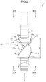
- FIG. 2 is a plan view of the kneading rotor 4 shown in FIG. 1 .
- FIGS. 3A and 3B are a view along arrows IIIA-IIIA depicted in FIG. 2 and a view along arrows IIIB-IIIB depicted in FIG. 2 , respectively.
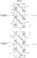
- FIG. 4 is a developed diagram of body portions 20 of the kneading rotors 4 and 5 shown in FIG. 1 around an axis.
- FIG. 5 is an enlarged diagram of the developed diagram of the body portion 20 of the kneading rotor 4 shown in FIG. 4 around an axis.
- the kneading rotors 4 and 5 are disposed in the kneading room (chamber) 2 while being adjacent to each other so as to be parallel to each other.
- the kneading rotors 4 and 5 rotate in directions opposite to each other.
- the kneading rotors 4 and 5 are set to rotate such that rotor inside portions facing each other move downward.
- Each of the kneading rotors 4 and 5 includes a rotor shaft 21 having a shape extending in one direction and the body portion 20 positioned in an intermediate portion of an axial direction of the rotor shaft 21.
- the kneading rotors 4 and 5 are rotatably supported by bearings (not shown) at both sides of the body portions 20 in both of the rotor shafts 21.
- each body portion 20 a plurality of kneading wings 13 to 18 are disposed around an axis C of the rotor shaft 21. That is, the body portion 20 is a portion where the plurality of kneading wings 13 to 18 are formed on an outer peripheral surface.
- the kneading wings 13 to 18 pass the material to be kneaded through clearances between an inner surface of the casing 3 (inner wall surface forming the kneading room (chamber) 2)) and the kneading wings 13 to 18 (tip clearances) to give a shearing force to the material.
- the kneading wings 13 to 18 are spirally formed around the rotor axis C extending along a central axis of the rotor shaft 21. Since the kneading wings 13 to 18 are twisted around the rotor axis C, the material to be kneaded is pushed in a rotor axial direction Z. Therefore, when the kneading rotors 4 and 5 rotate, a flow of the material to be kneaded occurs in the axial direction.
- the tip clearances refer to clearances between wing tops (tip portions) 13a to 18a forming radial outer end surfaces (front end surfaces) of the kneading wings 13 to 18 and the inner surface of the casing 3. Note that if a height of the tip portion differs in a circumferential direction, the clearance of the narrowest portion is called tip clearance.
- FIG. 4 is a diagram in which the kneading rotors 4 and 5 are developed around the axis C.
- each of the kneading wings 13 to 18 of the kneading rotor 4 and each of the kneading wings 13 to 18 of the kneading rotor 5 are disposed so as to be point symmetrical with respect to a center point O in a state of being developed in the circumferential direction.
- two kneading rotors having the same shape are installed in directions opposite to each other.
- the twist direction of the kneading wings 13 to 18 in the kneading rotor 4 is the same as the twist direction of the kneading wings 13 to 18 in the kneading rotor 5.
- long wings 13 to 15 and short wings 16 to 18 to be described later are disposed in the kneading room (chamber) 2 in a positional relationship opposite to each other in the rotor axial direction Z.
- the kneading rotor 4 will be described as a representative.
- the kneading rotor 4 of the present embodiment includes six kneading wings 13 to 18.
- the six kneading wings 13 to 18 include three long wings 13 to 15 and three short wings 16 to 18.
- the long wings 13 to 15 are all disposed from a first end to the intermediate portion of the rotor axial direction Z in the body portion 20.
- the short wings 16 to 18 are all disposed from a second end to the intermediate portion of the rotor axial direction Z in the body portion 20.
- a developed shape from a start point to an end point of the long wings 13 to 15 extends from a first end side of the rotor axial direction Z toward a second end side of the rotor axial direction Z.
- the short wings 16 to 18 extend from the second end side of the rotor axial direction Z toward the first end side of the rotor axial direction Z.
- the short wings 16 to 18 are twisted so that the short wings move toward the first end in the rotor axial direction Z, whereas the long wings 13 to 15 are twisted so that the long wings move toward the second end in the rotor axial direction Z.
- the long wings 13 to 15 are disposed in a range longer than half of the length (wing length) W of the range where the kneading wings 13 to 18 are disposed in the rotor axial direction Z.
- the long wings 13 to 15 are twisted at an angle of twist angle ⁇ L in a direction of flowing the material to be kneaded toward the second end side of the rotor axial direction Z.
- the twist angle ⁇ L is an inclination angle with respect to the rotor axial direction Z.
- the short wings 16 to 18 are disposed in a range shorter than half of the wing length W.
- the short wings 16 to 18 are twisted at an angle of twist angle ⁇ S in a direction to flow the material to be kneaded toward the first end side of the rotor axial direction Z.
- the length of the long wings 13 to 15 in the rotor axial direction Z is 0.75 times the wing length W
- the length of the short wings 16 to 18 in the rotor axial direction Z is 0.25 times the wing length W. That is, a length ratio of the long wings to the short wings (long wings/short wings) is 3.
- the long wings 13 to 15 all have two stages of different heights in the wing longitudinal direction. That is, the wing tops (front end surfaces) of the long wings 13 to 15 include low tip portions 13a to 15a and high tip portions 13b to 15b positioned radially outside the low tip portions 13a to 15a, respectively. That is, the long wings 13 to 15 include first portions where the outer end surfaces are low tip portions 13a to 15a, and second portions larger than the first portions in diameter where the outer end surfaces are high tip portions 13b to 15b. The first portions and the second portions are continuous to each other in the wing longitudinal direction.
- first tip clearances L The tip clearances formed between the inner surface of the casing 3 and the low tip portions 13a to 15a are referred to as first tip clearances L, whereas the tip clearances formed between the inner surface of the casing 3 and the high tip portions 13b to 15b are referred to as second tip clearances S.
- the second tip clearances S are narrower than the first tip clearances in radial width.
- the long wings 13 to 15 are formed such that two stages of different tip clearances appear along the wing longitudinal direction.
- the twist angle ⁇ L of the long wings 13 to 15 is between 38 degrees and 53 degrees inclusive. Since the twist angle ⁇ L is set between 38 degrees and 53 degrees inclusive, a CV value improves by 20% or more as compared with a case where the twist angle ⁇ L is 35 degrees. Details of this point will be described later.
- the twist angle ⁇ L of the long wings may be between 40 degrees and 50 degrees inclusive. By setting the twist angle ⁇ L between 40 degrees and 50 degrees inclusive, the CV value improves by 30% or more. Details of this point will also be described later.
- a ratio of the first tip clearances L of the long wings 13 to 15 (tip clearances at the low tip portions 13a to 15a) to the inner diameter of the casing 3 may be within a range of 0.02 to 0.07. In this case, further improvement in the CV value will be described later.
- a ratio of the first tip clearances L of the long wings 13 to 15 (tip clearances at the low tip portions 13a to 15a) to the inner diameter of the casing 3 may be within a range of 0.03 to 0.06.
- a central angle ⁇ c of the high tip portions 13b to 15b forming the second tip clearances S to the inner surface of the casing 3 may be between 5 degrees and 10 degrees inclusive. Since the central angle ⁇ c of the high tip portions 13b to 15b of the long wings 13 to 15 is set between 5 degrees and 10 degrees inclusive, productivity of the kneaded product can be increased. Details of this point will be described later.
- An influence of heights of the wing tops (tip clearances), the central angles, the twist angles ⁇ S, and the like of the short wings 16 to 18 on the kneading of the material to be kneaded is smaller than an influence of the long wings 13 to 15. Therefore, the heights of the wing tops of the short wings 16 to 18 are not particularly limited.
- the heights of the short wings 16 to 18 are different from one another. That is, the short wing 18 has the high tip portion 18a, the short wing 17 has a medium tip portion 17a, the short wing 16 has the low tip portion 16a, and the short wings 16 to 18 have tip heights different from one another. That is, the short wings 16 to 18 have three stages of height in total. Note that the short wings 16 to 18 each have a constant height along the wing longitudinal direction. In this regard, the short wings 16 to 18 are different from the long wings 13 to 15 each having two stages of height.
- the high tip portion 18a forms the second tip clearance S to the inner surface of the casing 3.
- the medium tip portion 17a forms a third tip clearance M to the inner surface of the casing 3.
- the low tip portion 16a forms the first tip clearance L to the inner surface of the casing 3. Note that there is a relationship of second tip clearance S ⁇ third tip clearance M ⁇ first tip clearance L. There is no particular relationship between sizes of the tip clearances S and L in the long wings 13 to 15 and sizes of the tip clearances S and L in the short wings 18 and 16.
- the long wings 13 to 15 and the short wing 18 may be formed such that the second tip clearances S (the smallest tip clearance) are 3.2 mm or more.
- the inventors of the present invention have eagerly studied the kneading rotor capable of improving kneading performance of the material to be kneaded (material dispersibility) and increasing productivity of the kneaded product. This will be described below. This study mainly compares the kneading rotor having three long wings and three short wings, and in which the tip clearance of the long wings changes in three stages as disclosed in Japanese Patent No. 4024976 .
- An index of kneading performance of the material to be kneaded includes the CV value. As this CV value decreases, the kneading performance of the material to be kneaded improves. In addition, the productivity of the kneaded product is affected by energy given to the material to be kneaded (kneading energy) and space volume of the kneading room (chamber) 2. It is possible to increase the productivity of the kneaded product by increasing the energy given to the material to be kneaded (kneading energy) and increasing the space volume of the kneading room (chamber) 2.
- the space volume of the kneading room (chamber) 2 mentioned here refers to empty volume of the kneading room (chamber) 2 with the kneading rotors 4 and 5 disposed in the kneading room (chamber) 2 (in the casing 3).
- Factors affecting the performance of the kneading rotor include a wing length ratio of the kneading rotor (ratio of the long wing length to the short wing length), biting angle, central angle, twist angle of the long wing, twist angle of the short wing, and tip clearance.
- the inventors of the present invention have eagerly studied which factor stably and greatly affects the performance of the kneading rotor by a method such as flow analysis by changing such various factors.
- the biting angle refers to, for example, as shown in FIG. 3A , an angle ( ⁇ k (0 degrees ⁇ ⁇ k ⁇ 90 degrees)) formed by a straight line L2 and a tangential line L3 of the kneading wing.
- the straight line L2 is perpendicular to a straight line L1 connecting an end point r1 of a rotation direction r in the front end surface of the kneading wings 13, 14, 15 (tip portion 15b or wing top) and the rotor axis C.
- the tangential line L3 passes through the end point r1 of the rotation direction r on the front end surface.
- the central angle ⁇ c refers to an angle around the rotor axis C that defines the widths of the front end surface of the kneading wings 13, 14, and 15.
- the central angle ⁇ c is represented as an angle ( ⁇ c (0 degrees ⁇ ⁇ c ⁇ 180 degrees)) formed by two straight lines connecting the both end points r1 and r2 of the rotation direction r in the front end surface of the kneading wing (tip portion 15b or wing top) and the rotor axis C.
- the inventors of the present invention have found that although there are many factors that affect the performance of the kneading rotor as described above, specified factors greatly affect the kneading performance of the material to be kneaded or the productivity of the kneaded product.
- the CV value which is an index of the kneading performance of the material to be kneaded, is stably and greatly affected by the twist angle of the long wing and the large tip clearance (the first tip clearance).
- the productivity of the kneaded product is stably and greatly affected by the central angle of the high tip portion that causes the small tip clearance (the second tip clearance) to appear in the long wing (for example, the tip portion 15b shown in FIGS. 3A and 5 ).
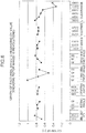
- FIG. 6 is a graph of factorial effects regarding the CV value when the kneading rotor makes 10 revolutions.
- FIG. 7 is a graph of factorial effects regarding the CV value when the kneading rotor makes 16 revolutions.
- the S clearance, M clearance, and L clearance described in FIGS. 6 and 7 are the clearances formed by the long wings, and refer to the second tip clearance S with a small clearance, the third tip clearance M with a medium clearance, and the first tip clearance L with a large clearance, respectively.
- Numerical values described in each clearance column are a ratio of the clearance to the inner diameter of the casing 3.
- FIGS. 6 and 7 show that the CV value greatly changes in a case where the twist angle of the long wing differs and a case where the first tip clearance L of the long wing differs. That is, FIGS. 6 and 7 show that the CV value is stably and greatly affected by the twist angle of the long wing and the first tip clearance L.
- the inventors of the present invention have investigated a relationship between the twist angle of the long wing and the CV value. A result of the investigation is shown in FIG. 9 .
- the twist angle ⁇ L of the long wing is preferably between 38 degrees and 53 degrees inclusive. Since the twist angle ⁇ L is set between 38 degrees and 53 degrees inclusive, the CV value improves by 20% or more as compared with a case where the twist angle ⁇ L is 35 degrees. Note that the twist angle ⁇ L of the long wing may be between 40 degrees and 50 degrees inclusive. When the twist angle ⁇ L is set between 40 degrees and 50 degrees inclusive, the CV value improves by 30% or more. Note that as the twist angle ⁇ L increases, the CV value turns from decreasing to increasing when ⁇ L exceeds around 45 degrees.
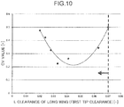
- the inventors of the present invention have investigated a relationship between the first tip clearance of the long wing and the CV value as well. A result of the investigation is shown in FIG. 10 .
- the ratio of the first tip clearance L of the long wing (for example, the long wings 13 to 15 shown in FIGS. 2 to 5 ) to the inner diameter of the casing 3 is preferably 0.07 or less.
- the lower limit of the first tip clearance L is about 0.02 in terms of the ratio to the inner diameter of the casing 3. That is, the ratio of the first tip clearance L of the long wings to the inner diameter of the casing 3 is preferably in the range of 0.02 to 0.07.
- the ratio of the first tip clearance L of the long wings to the inner diameter of the casing 3 may be in the range of 0.03 to 0.06. In this case, the CV value is higher by about 40% as compared with a case where the ratio is 0.02.
- FIG. 8 is a graph of factorial effects regarding productivity.
- the productivity (%) of the kneaded product which is the product of the kneading energy and the space volume of the kneading room 2 is plotted on a vertical axis.
- the central angle described in FIG. 8 is the central angle of the high tip portion of the long wings.
- the S clearance, M clearance, and L clearance described in FIG. 8 are the clearances formed by the long wings, and refer to the second tip clearance with a small clearance, the third tip clearance with a medium clearance, and the first tip clearance with a large clearance, respectively.
- Numerical values described in the column of M clearance represent the ratio of the clearance to the inner diameter of the casing 3.
- FIG. 8 shows that the productivity of the kneaded product greatly changes when the central angle of the high tip portion of the long wings is changed. That is, FIG. 8 shows that the productivity of the kneaded product is stably and greatly affected by the central angle of the high tip portion of the long wings.
- the productivity of the kneaded product which is the product of the kneading energy and the space volume of the kneading room 2, is stably and greatly affected by the central angle of the high tip portion of the long wings. Therefore, the inventors of the present invention have investigated the relationship between the central angle of the high tip portion of the long wings and the kneading energy. A result of the investigation is shown in FIG. 11 . As shown in FIG. 11 , the kneading energy increases as the central angle of the high tip portion of the long wings increases.
- FIG. 12 shows a relationship between the central angle of the high tip portion of the long wings and the space volume (empty volume) of the kneading room (chamber) 2.
- the space volume of the kneading room (chamber) 2 decreases.
- the throughput per batch decreases. Therefore, as the central angle of the high tip portion of the long wings increases, the throughput of the material to be kneaded decreases.
- the central angle of the high tip portion of the long wings is not necessarily required to be large, and needs to be determined in relation to the kneading energy and the space volume of the kneading room 2.
- the inventors of the present invention have found that when the central angle of the high tip portion of the long wings (for example, ⁇ c shown in FIG. 3A ) is between 5 degrees and 10 degrees inclusive, the productivity of the kneaded product can be further increased as compared with the kneading rotor having six kneading wings as described in Japanese Patent No. 4024976 .
- the present invention can also be applied to a uniaxial kneading rotor (kneading apparatus).
- the length of the rotor axial direction Z in the low tip portions 13a to 15a forming the first tip clearance L is set at 0.5 times the length (wing length) W of the range in which the kneading wings 13 to 18 are disposed, and the length of the rotor axial direction Z of the high tip portions 13b to 15b is set at 0.25 times the wing length W. That is, in the rotor axial direction Z, the low tip portions 13a to 15a are longer than the high tip portions 13b to 15b.
- the low tip portions 13a to 15a may be shorter than the high tip portions 13b to 15b in the rotor axial direction Z, for example, the length of the rotor axial direction Z of the low tip portions 13a to 15a of the long wings 13 to 15 is 0.25 W, and the length of the rotor axial direction Z of the high tip portions 13b to 15b is 0.5 W. Also, in the rotor axial direction Z, the length of the low tip portions 13a to 15a may be the same as the length of the high tip portions 13b to 15b.
- the tip clearance formed by the long wings 13 to 15 is formed in two stages, respectively, but the invention is not limited to this example.
- the tip clearance may be formed in three or more stages.
Landscapes
- Engineering & Computer Science (AREA)
- Mechanical Engineering (AREA)
- Chemical & Material Sciences (AREA)
- Chemical Kinetics & Catalysis (AREA)
- Processing And Handling Of Plastics And Other Materials For Molding In General (AREA)
- Mixers Of The Rotary Stirring Type (AREA)
Abstract
Description
- The present invention relates to a kneading rotor and a batch-type kneading apparatus.
- A batch-type kneading apparatus is a kneading apparatus that can produce a batch of kneaded product. The kneading apparatus includes a hopper portion into which a polymer material such as rubber or plastic (material to be kneaded) is injected, a kneading room (chamber) into which the material to be kneaded is pressed from inside the hopper portion, and a kneading rotor disposed in the kneading room (chamber). The kneading rotor kneads the material to be kneaded and the kneaded product in a desired kneaded state is discharged to the outside. This produces a batch of kneaded product. The kneading rotor is a main component for kneading the material to be kneaded among components constituting the batch-type kneading apparatus. Conventionally, for example, the technique related to a kneading rotor as described below has been proposed.
-
Patent Literature 1 proposes a kneading rotor in which a small tip clearance with a ratio of clearance to an inner diameter of a casing in the range of 0.0025 to 0.0250, a medium tip clearance with a ratio in the range of 0.0100 to 0.0500, and a large tip clearance with a ratio in the range of 0.0250 to 0.1000 are formed (see, for example, Patent Literature 1). - According to the kneading rotor disclosed in
Patent Literature 1, even if a type of material to be kneaded changes, a shearing force acts reliably on the material to be kneaded, and the material to be kneaded is well kneaded in the kneading room (chamber). - In recent years, demand for fuel-efficient tires has increased. In rubber that is a raw material of fuel-efficient tires, silica is often blended in a high proportion. The rubber in which silica is blended in a high proportion (material to be kneaded) has the property that the silica in the rubber tends to become so-called "lump of silica" and is hardly dispersed. Therefore, further improvement in material kneading performance of a kneading rotor is desired.
- Patent Literature 1: Japanese Patent No.
4024976 - An object of the present invention is to provide a kneading rotor that can improve kneading performance of a material to be kneaded and can increase productivity of a kneaded product.
- A kneading rotor according to one aspect of the present invention is a kneading rotor rotatably disposed in a casing of a batch-type kneading apparatus. The kneading rotor includes: a rotor shaft; and kneading wings configured to rotate integrally with the rotor shaft to apply a shearing force to a material to be kneaded by passing the material to be kneaded through a clearance between the kneading wings and an inner surface of the casing. The kneading wings include: long wings extending from a first end side of a rotor axial direction; and short wings extending from a second end side of the rotor axial direction. Each of the long wings is disposed in a range longer than half of a length of a range, in the rotor axial direction, in which the kneading wings are disposed, and each of the long wings is twisted in a direction of flowing the material to be kneaded toward the second end side of the rotor axial direction when the rotor shaft rotates. Each of the short wings is disposed in a range shorter than half of the length of the range, in the rotor axial direction, in which the kneading wings are disposed, and each of the short wings is twisted in a direction of flowing the material to be kneaded toward the first end side of the rotor axial direction when the rotor shaft rotates. A twist angle of each of the long wings is between 38 degrees and 53 degrees inclusive. Each of the long wings includes, between each of the long wings and the inner surface of the casing, a wing top configured to form, along a wing longitudinal direction, a first tip clearance, and a second tip clearance narrower than the first tip clearance in width. A central angle around a rotor axis defining a width of the wing top forming the second tip clearance is between 5 degrees and 10 degrees inclusive.
-
-
FIG. 1 is a front cross-sectional view of a batch-type kneading apparatus including kneading rotors according to an embodiment; -
FIG. 2 is a plan view of the kneading rotor shown inFIG. 1 ; -
FIG. 3A is a view along arrows IIIA-IIIA ofFIG. 2 ; -
FIG. 3B is a view along arrows IIIB-IIIB ofFIG. 2 ; -
FIG. 4 is a developed diagram of a body portion of the kneading rotor shown inFIG. 1 around an axis; -
FIG. 5 is an enlarged diagram of the developed diagram of the body portion of the kneading rotor shown inFIG. 4 ; -
FIG. 6 is a graph of factorial effects regarding a CV value when the kneading rotor makes 10 revolutions; -
FIG. 7 is a graph of factorial effects regarding the CV value when the kneading rotor makes 16 revolutions; -
FIG. 8 is a graph of factorial effects regarding productivity; -
FIG. 9 is a diagram showing a relationship between a twist angle of a long wing and the CV value; -
FIG. 10 is a diagram showing a relationship between a large tip clearance of the long wing and the CV value; -
FIG. 11 is a diagram showing a relationship between a central angle of a high tip portion of the long wing and kneading energy; and -
FIG. 12 is a diagram showing a relationship between the central angle of the high tip portion of the long wing and space volume of a kneading room (chamber). - An embodiment will be described below with reference to the drawings. Note that the following embodiment is one example of embodying the present invention, and does not limit the technical scope of the present invention.
FIG. 1 is a front cross-sectional view of a batch-type kneading apparatus 1 includingkneading rotors type kneading apparatus 1 is also called an enclosed kneading apparatus. The batch-type kneading apparatus 1 is used for kneading polymer materials such as plastic and rubber. - First, the configuration of the batch-
type kneading apparatus 1 will be described with reference toFIG. 1 . As shown inFIG. 1 , the batch-type kneading apparatus 1 includes acasing 3 including a kneading room (chamber) 2, one pair of right andleft kneading rotors material supply tube 7 erected on an upper portion of thecasing 3, and afloating weight 8 disposed in thematerial supply tube 7 in a vertically movable manner. The vertical cross section of the kneading room (chamber) 2 has a shape of two overlapping circles. An opening is formed in an upper portion of thecasing 3, and inner space of thematerial supply tube 7 communicates with the kneading room (chamber) 2 through the opening. A hopper 6 is attached to thematerial supply tube 7. - A
pneumatic cylinder 9 is connected to an upper portion of thematerial supply tube 7. Apiston 10 in thepneumatic cylinder 9 is connected to the floatingweight 8 via apiston rod 11 that passes airtightly through a lower lid of thepneumatic cylinder 9. When an upper portion of thepneumatic cylinder 9 is pressurized and thefloating weight 8 is lowered, the material to be kneaded in thematerial supply tube 7 supplied from the hopper 6 is pushed into the kneading room (chamber) 3 of thecasing 3. An outlet formed at the bottom of thecasing 3 is closed by adrop door 12 that can be opened and closed by a rotary actuator. When thedrop door 12 is opened, the kneaded product kneaded for a predetermined time in the kneading room (chamber) 2 (material that has already been kneaded) is discharged from the kneading room (chamber) 2. Note that the batch-type kneading apparatus 1 of the present embodiment is a non-intermeshing kneading apparatus having one pair of right andleft kneading rotors pneumatic cylinder 9, a hydraulic cylinder may be used. -
FIG. 2 is a plan view of thekneading rotor 4 shown inFIG. 1 .FIGS. 3A and 3B are a view along arrows IIIA-IIIA depicted inFIG. 2 and a view along arrows IIIB-IIIB depicted inFIG. 2 , respectively.FIG. 4 is a developed diagram ofbody portions 20 of the kneadingrotors FIG. 1 around an axis.FIG. 5 is an enlarged diagram of the developed diagram of thebody portion 20 of the kneadingrotor 4 shown inFIG. 4 around an axis. - The kneading
rotors rotors rotors rotors rotor shaft 21 having a shape extending in one direction and thebody portion 20 positioned in an intermediate portion of an axial direction of therotor shaft 21. The kneadingrotors body portions 20 in both of therotor shafts 21. - In each
body portion 20, a plurality of kneadingwings 13 to 18 are disposed around an axis C of therotor shaft 21. That is, thebody portion 20 is a portion where the plurality of kneadingwings 13 to 18 are formed on an outer peripheral surface. When rotating around the axis C, the kneadingwings 13 to 18 pass the material to be kneaded through clearances between an inner surface of the casing 3 (inner wall surface forming the kneading room (chamber) 2)) and the kneadingwings 13 to 18 (tip clearances) to give a shearing force to the material. The kneadingwings 13 to 18 are spirally formed around the rotor axis C extending along a central axis of therotor shaft 21. Since the kneadingwings 13 to 18 are twisted around the rotor axis C, the material to be kneaded is pushed in a rotor axial direction Z. Therefore, when the kneadingrotors wings 13 to 18 and the inner surface of thecasing 3. Note that if a height of the tip portion differs in a circumferential direction, the clearance of the narrowest portion is called tip clearance. -
FIG. 4 is a diagram in which the kneadingrotors FIG. 4 , each of the kneadingwings 13 to 18 of the kneadingrotor 4 and each of the kneadingwings 13 to 18 of the kneadingrotor 5 are disposed so as to be point symmetrical with respect to a center point O in a state of being developed in the circumferential direction. In other words, two kneading rotors having the same shape are installed in directions opposite to each other. Specifically, the twist direction of the kneadingwings 13 to 18 in the kneadingrotor 4 is the same as the twist direction of the kneadingwings 13 to 18 in the kneadingrotor 5. Meanwhile, in the kneadingrotors long wings 13 to 15 andshort wings 16 to 18 to be described later are disposed in the kneading room (chamber) 2 in a positional relationship opposite to each other in the rotor axial direction Z. In the following description, the kneadingrotor 4 will be described as a representative. - As shown in
FIGS. 2 and4 , the kneadingrotor 4 of the present embodiment includes six kneadingwings 13 to 18. The sixkneading wings 13 to 18 include threelong wings 13 to 15 and threeshort wings 16 to 18. Thelong wings 13 to 15 are all disposed from a first end to the intermediate portion of the rotor axial direction Z in thebody portion 20. Theshort wings 16 to 18 are all disposed from a second end to the intermediate portion of the rotor axial direction Z in thebody portion 20. When the kneadingrotor 4 is developed to a flat state around the axis C, a developed shape from a start point to an end point of thelong wings 13 to 15 extends from a first end side of the rotor axial direction Z toward a second end side of the rotor axial direction Z. Meanwhile, theshort wings 16 to 18 extend from the second end side of the rotor axial direction Z toward the first end side of the rotor axial direction Z. That is, when the kneadingrotor 4 rotates in one direction, theshort wings 16 to 18 are twisted so that the short wings move toward the first end in the rotor axial direction Z, whereas thelong wings 13 to 15 are twisted so that the long wings move toward the second end in the rotor axial direction Z. - The
long wings 13 to 15 are disposed in a range longer than half of the length (wing length) W of the range where the kneadingwings 13 to 18 are disposed in the rotor axial direction Z. Thelong wings 13 to 15 are twisted at an angle of twist angle θL in a direction of flowing the material to be kneaded toward the second end side of the rotor axial direction Z. Note that the twist angle θL is an inclination angle with respect to the rotor axial direction Z. Theshort wings 16 to 18 are disposed in a range shorter than half of the wing length W. Theshort wings 16 to 18 are twisted at an angle of twist angle θS in a direction to flow the material to be kneaded toward the first end side of the rotor axial direction Z. In the present embodiment, the length of thelong wings 13 to 15 in the rotor axial direction Z is 0.75 times the wing length W, and the length of theshort wings 16 to 18 in the rotor axial direction Z is 0.25 times the wing length W. That is, a length ratio of the long wings to the short wings (long wings/short wings) is 3. - The
long wings 13 to 15 all have two stages of different heights in the wing longitudinal direction. That is, the wing tops (front end surfaces) of thelong wings 13 to 15 includelow tip portions 13a to 15a andhigh tip portions 13b to 15b positioned radially outside thelow tip portions 13a to 15a, respectively. That is, thelong wings 13 to 15 include first portions where the outer end surfaces arelow tip portions 13a to 15a, and second portions larger than the first portions in diameter where the outer end surfaces arehigh tip portions 13b to 15b. The first portions and the second portions are continuous to each other in the wing longitudinal direction. The tip clearances formed between the inner surface of thecasing 3 and thelow tip portions 13a to 15a are referred to as first tip clearances L, whereas the tip clearances formed between the inner surface of thecasing 3 and thehigh tip portions 13b to 15b are referred to as second tip clearances S. The second tip clearances S are narrower than the first tip clearances in radial width. Thelong wings 13 to 15 are formed such that two stages of different tip clearances appear along the wing longitudinal direction. - The twist angle θL of the
long wings 13 to 15 is between 38 degrees and 53 degrees inclusive. Since the twist angle θL is set between 38 degrees and 53 degrees inclusive, a CV value improves by 20% or more as compared with a case where the twist angle θL is 35 degrees. Details of this point will be described later. The twist angle θL of the long wings may be between 40 degrees and 50 degrees inclusive. By setting the twist angle θL between 40 degrees and 50 degrees inclusive, the CV value improves by 30% or more. Details of this point will also be described later. - A ratio of the first tip clearances L of the
long wings 13 to 15 (tip clearances at thelow tip portions 13a to 15a) to the inner diameter of thecasing 3 may be within a range of 0.02 to 0.07. In this case, further improvement in the CV value will be described later. A ratio of the first tip clearances L of thelong wings 13 to 15 (tip clearances at thelow tip portions 13a to 15a) to the inner diameter of thecasing 3 may be within a range of 0.03 to 0.06. - A central angle θc of the
high tip portions 13b to 15b forming the second tip clearances S to the inner surface of thecasing 3 may be between 5 degrees and 10 degrees inclusive. Since the central angle θc of thehigh tip portions 13b to 15b of thelong wings 13 to 15 is set between 5 degrees and 10 degrees inclusive, productivity of the kneaded product can be increased. Details of this point will be described later. - An influence of heights of the wing tops (tip clearances), the central angles, the twist angles θS, and the like of the
short wings 16 to 18 on the kneading of the material to be kneaded is smaller than an influence of thelong wings 13 to 15. Therefore, the heights of the wing tops of theshort wings 16 to 18 are not particularly limited. - In the present embodiment, the heights of the
short wings 16 to 18 are different from one another. That is, theshort wing 18 has thehigh tip portion 18a, theshort wing 17 has amedium tip portion 17a, theshort wing 16 has thelow tip portion 16a, and theshort wings 16 to 18 have tip heights different from one another. That is, theshort wings 16 to 18 have three stages of height in total. Note that theshort wings 16 to 18 each have a constant height along the wing longitudinal direction. In this regard, theshort wings 16 to 18 are different from thelong wings 13 to 15 each having two stages of height. - The
high tip portion 18a forms the second tip clearance S to the inner surface of thecasing 3. Themedium tip portion 17a forms a third tip clearance M to the inner surface of thecasing 3. Thelow tip portion 16a forms the first tip clearance L to the inner surface of thecasing 3. Note that there is a relationship of second tip clearance S < third tip clearance M < first tip clearance L. There is no particular relationship between sizes of the tip clearances S and L in thelong wings 13 to 15 and sizes of the tip clearances S and L in theshort wings - If the sizes of the second tip clearances S appeared by the
long wings 13 to 15 and theshort wing 18 are too small, there is a possibility that the tip portions (wing tops) interfere with the inner surface of thecasing 3, the floatingweight 8, thedrop door 12, or the like. Therefore, thelong wings 13 to 15 and theshort wing 18 may be formed such that the second tip clearances S (the smallest tip clearance) are 3.2 mm or more. - The inventors of the present invention have eagerly studied the kneading rotor capable of improving kneading performance of the material to be kneaded (material dispersibility) and increasing productivity of the kneaded product. This will be described below. This study mainly compares the kneading rotor having three long wings and three short wings, and in which the tip clearance of the long wings changes in three stages as disclosed in Japanese Patent No.
4024976 - An index of kneading performance of the material to be kneaded includes the CV value. As this CV value decreases, the kneading performance of the material to be kneaded improves. In addition, the productivity of the kneaded product is affected by energy given to the material to be kneaded (kneading energy) and space volume of the kneading room (chamber) 2. It is possible to increase the productivity of the kneaded product by increasing the energy given to the material to be kneaded (kneading energy) and increasing the space volume of the kneading room (chamber) 2. Note that the space volume of the kneading room (chamber) 2 mentioned here refers to empty volume of the kneading room (chamber) 2 with the kneading
rotors - Factors affecting the performance of the kneading rotor include a wing length ratio of the kneading rotor (ratio of the long wing length to the short wing length), biting angle, central angle, twist angle of the long wing, twist angle of the short wing, and tip clearance. The inventors of the present invention have eagerly studied which factor stably and greatly affects the performance of the kneading rotor by a method such as flow analysis by changing such various factors.
- The biting angle refers to, for example, as shown in
FIG. 3A , an angle (θk (0 degrees < θk < 90 degrees)) formed by a straight line L2 and a tangential line L3 of the kneading wing. The straight line L2 is perpendicular to a straight line L1 connecting an end point r1 of a rotation direction r in the front end surface of the kneadingwings tip portion 15b or wing top) and the rotor axis C. The tangential line L3 passes through the end point r1 of the rotation direction r on the front end surface. The central angle θc refers to an angle around the rotor axis C that defines the widths of the front end surface of the kneadingwings FIG. 3A , the central angle θc is represented as an angle (θc (0 degrees < θc < 180 degrees)) formed by two straight lines connecting the both end points r1 and r2 of the rotation direction r in the front end surface of the kneading wing (tip portion 15b or wing top) and the rotor axis C. - As a result of the eager study, the inventors of the present invention have found that although there are many factors that affect the performance of the kneading rotor as described above, specified factors greatly affect the kneading performance of the material to be kneaded or the productivity of the kneaded product. Specifically, the CV value, which is an index of the kneading performance of the material to be kneaded, is stably and greatly affected by the twist angle of the long wing and the large tip clearance (the first tip clearance). The productivity of the kneaded product is stably and greatly affected by the central angle of the high tip portion that causes the small tip clearance (the second tip clearance) to appear in the long wing (for example, the
tip portion 15b shown inFIGS. 3A and5 ). -
FIG. 6 is a graph of factorial effects regarding the CV value when the kneading rotor makes 10 revolutions.FIG. 7 is a graph of factorial effects regarding the CV value when the kneading rotor makes 16 revolutions. The S clearance, M clearance, and L clearance described inFIGS. 6 and7 are the clearances formed by the long wings, and refer to the second tip clearance S with a small clearance, the third tip clearance M with a medium clearance, and the first tip clearance L with a large clearance, respectively. Numerical values described in each clearance column are a ratio of the clearance to the inner diameter of thecasing 3. -
FIGS. 6 and7 show that the CV value greatly changes in a case where the twist angle of the long wing differs and a case where the first tip clearance L of the long wing differs. That is,FIGS. 6 and7 show that the CV value is stably and greatly affected by the twist angle of the long wing and the first tip clearance L. - Since the CV value (kneading performance of the material to be kneaded) is stably and greatly affected by the twist angle of the long wing, the inventors of the present invention have investigated a relationship between the twist angle of the long wing and the CV value. A result of the investigation is shown in
FIG. 9 . - As shown in
FIG. 9 , the twist angle θL of the long wing (for example, thelong wings 13 to 15 shown inFIGS. 2 to 5 ) is preferably between 38 degrees and 53 degrees inclusive. Since the twist angle θL is set between 38 degrees and 53 degrees inclusive, the CV value improves by 20% or more as compared with a case where the twist angle θL is 35 degrees. Note that the twist angle θL of the long wing may be between 40 degrees and 50 degrees inclusive. When the twist angle θL is set between 40 degrees and 50 degrees inclusive, the CV value improves by 30% or more. Note that as the twist angle θL increases, the CV value turns from decreasing to increasing when θL exceeds around 45 degrees. This is because the feedability of the material to be kneaded weakens when the twist angle θL exceeds 45 degrees. That is, when the twist angle θL becomes excessive, the push in a direction parallel to the axial direction relatively weakens. In addition to the fact that the factor that stably and greatly affects the CV value, which is the index of the kneading performance of the material to be kneaded, is the twist angle of the long wing, it can be seen that there is a suitable range of the twist angle. - In addition to the twist angle of the long wing, the first tip clearance of the long wing also affects the CV value stably and greatly. Therefore, the inventors of the present invention have investigated a relationship between the first tip clearance of the long wing and the CV value as well. A result of the investigation is shown in
FIG. 10 . - As shown in
FIG. 10 , the ratio of the first tip clearance L of the long wing (for example, thelong wings 13 to 15 shown inFIGS. 2 to 5 ) to the inner diameter of thecasing 3 is preferably 0.07 or less. Note that the lower limit of the first tip clearance L is about 0.02 in terms of the ratio to the inner diameter of thecasing 3. That is, the ratio of the first tip clearance L of the long wings to the inner diameter of thecasing 3 is preferably in the range of 0.02 to 0.07. The ratio of the first tip clearance L of the long wings to the inner diameter of thecasing 3 may be in the range of 0.03 to 0.06. In this case, the CV value is higher by about 40% as compared with a case where the ratio is 0.02. -
FIG. 8 is a graph of factorial effects regarding productivity. InFIG. 8 , the productivity (%) of the kneaded product, which is the product of the kneading energy and the space volume of thekneading room 2, is plotted on a vertical axis. The central angle described inFIG. 8 is the central angle of the high tip portion of the long wings. The S clearance, M clearance, and L clearance described inFIG. 8 are the clearances formed by the long wings, and refer to the second tip clearance with a small clearance, the third tip clearance with a medium clearance, and the first tip clearance with a large clearance, respectively. Numerical values described in the column of M clearance represent the ratio of the clearance to the inner diameter of thecasing 3. For example, "M - 8.8 × 10⁻³" described in the column of S clearance is the tip clearance indicated with a difference from the corresponding M clearance (M = 0.014). The same applies to the column of L clearance. -
FIG. 8 shows that the productivity of the kneaded product greatly changes when the central angle of the high tip portion of the long wings is changed. That is,FIG. 8 shows that the productivity of the kneaded product is stably and greatly affected by the central angle of the high tip portion of the long wings. - The productivity of the kneaded product, which is the product of the kneading energy and the space volume of the
kneading room 2, is stably and greatly affected by the central angle of the high tip portion of the long wings. Therefore, the inventors of the present invention have investigated the relationship between the central angle of the high tip portion of the long wings and the kneading energy. A result of the investigation is shown inFIG. 11 . As shown inFIG. 11 , the kneading energy increases as the central angle of the high tip portion of the long wings increases. -
FIG. 12 shows a relationship between the central angle of the high tip portion of the long wings and the space volume (empty volume) of the kneading room (chamber) 2. As shown inFIG. 12 , as the central angle of the high tip portion of the long wings increases, the space volume of the kneading room (chamber) 2 decreases. As the space volume of the kneading room (chamber) 2 decreases, the throughput per batch decreases. Therefore, as the central angle of the high tip portion of the long wings increases, the throughput of the material to be kneaded decreases. That is, the central angle of the high tip portion of the long wings is not necessarily required to be large, and needs to be determined in relation to the kneading energy and the space volume of thekneading room 2. As a result of the eager study, the inventors of the present invention have found that when the central angle of the high tip portion of the long wings (for example, θc shown inFIG. 3A ) is between 5 degrees and 10 degrees inclusive, the productivity of the kneaded product can be further increased as compared with the kneading rotor having six kneading wings as described in Japanese Patent No.4024976 - The embodiment has been described above. Note that various modifications can be made within the scope those skilled in the art can assume.
- For example, although the above embodiment has illustrated a non-intermeshing (tangential) kneading rotor (kneading apparatus), the present invention can also be applied to a uniaxial kneading rotor (kneading apparatus).
- In the embodiment shown in
FIGS. 4 and5 , in thelong wings 13 to 15, the length of the rotor axial direction Z in thelow tip portions 13a to 15a forming the first tip clearance L is set at 0.5 times the length (wing length) W of the range in which the kneadingwings 13 to 18 are disposed, and the length of the rotor axial direction Z of thehigh tip portions 13b to 15b is set at 0.25 times the wing length W. That is, in the rotor axial direction Z, thelow tip portions 13a to 15a are longer than thehigh tip portions 13b to 15b. Alternatively, thelow tip portions 13a to 15a may be shorter than thehigh tip portions 13b to 15b in the rotor axial direction Z, for example, the length of the rotor axial direction Z of thelow tip portions 13a to 15a of thelong wings 13 to 15 is 0.25 W, and the length of the rotor axial direction Z of thehigh tip portions 13b to 15b is 0.5 W. Also, in the rotor axial direction Z, the length of thelow tip portions 13a to 15a may be the same as the length of thehigh tip portions 13b to 15b. - In the
long wings 13 to 15, the tip clearance formed by thelong wings 13 to 15 is formed in two stages, respectively, but the invention is not limited to this example. For example, the tip clearance may be formed in three or more stages. - Here, the embodiment will be outlined.
- (1) The above embodiment is a kneading rotor rotatably disposed in a casing of a batch-type kneading apparatus. The kneading rotor includes: a rotor shaft; and kneading wings configured to rotate integrally with the rotor shaft to apply a shearing force to a material to be kneaded by passing the material to be kneaded through a clearance between the kneading wings and an inner surface of the casing. The kneading wings include: long wings extending from a first end side of a rotor axial direction; and short wings extending from a second end side of the rotor axial direction. Each of the long wings is disposed in a range longer than half of a length of a range, in the rotor axial direction, in which the kneading wings are disposed, and each of the long wings is twisted in a direction of flowing the material to be kneaded toward the second end side of the rotor axial direction when the rotor shaft rotates. Each of the short wings is disposed in a range shorter than half of the length of the range, in the rotor axial direction, in which the kneading wings are disposed, and each of the short wings is twisted in a direction of flowing the material to be kneaded toward the first end side of the rotor axial direction when the rotor shaft rotates. A twist angle of each of the long wings is between 38 degrees and 53 degrees inclusive. Each of the long wings includes, between each of the long wings and the inner surface of the casing, a wing top configured to form, along a wing longitudinal direction, a first tip clearance, and a second tip clearance narrower than the first tip clearance in width. A central angle around a rotor axis defining a width of the wing top forming the second tip clearance is between 5 degrees and 10 degrees inclusive.
Since the twist angle of the long wing is between 38 degrees and 53 degrees inclusive in the kneading rotor, the kneading performance of the material to be kneaded can be improved. The wing top of the long wing is formed such that at least two stages of tip clearances with different widths appear along the wing longitudinal direction, and the central angle of the wing top of the long wing that causes the smaller second tip clearance to appear is between 5 degrees and 10 degrees inclusive. Therefore, the productivity of the kneaded product can be increased. - (2) The twist angle of each of the long wings may be between 40 degrees and 50 degrees inclusive.
- (3) Each of the long wings may have two stages of different heights in the wing longitudinal direction.
- (4) Each of the short wings may have a constant height along the wing longitudinal direction.
- (5) The short wings may have heights different from each other.
- (6) In the above embodiment, a batch-type kneading apparatus includes: a casing; and the kneading rotor disposed in the casing.
- (7) A ratio of the first tip clearance to an inner diameter of the casing may be in a range of 0.02 to 0.07.
- (8) Each of the long wings may be formed to make the second tip clearance 3.2 mm or more.
- (9) The kneading rotor may include one pair of left and right rotors.
Claims (9)
- A kneading rotor rotatably disposed in a casing of a batch-type kneading apparatus, the kneading rotor comprising:a rotor shaft; andkneading wings configured to rotate integrally with the rotor shaft to apply a shearing force to a material to be kneaded by passing the material to be kneaded through a clearance between the kneading wings and an inner surface of the casing,wherein the kneading wings include:long wings extending from a first end side of a rotor axial direction; andshort wings extending from a second end side of the rotor axial direction,each of the long wings is disposed in a range longer than half of a length of a range, in the rotor axial direction, in which the kneading wings are disposed, and each of the long wings is twisted in a direction of flowing the material to be kneaded toward the second end side of the rotor axial direction when the rotor shaft rotates,each of the short wings is disposed in a range shorter than half of the length of the range, in the rotor axial direction, in which the kneading wings are disposed, and each of the short wings is twisted in a direction of flowing the material to be kneaded toward the first end side of the rotor axial direction when the rotor shaft rotates,a twist angle of each of the long wings is between 38 degrees and 53 degrees inclusive,each of the long wings includes, between each of the long wings and the inner surface of the casing, a wing top configured to form, along a wing longitudinal direction, a first tip clearance, and a second tip clearance narrower than the first tip clearance in width, anda central angle around a rotor axis defining a width of the wing top forming the second tip clearance is between 5 degrees and 10 degrees inclusive.
- The kneading rotor according to claim 1, wherein
the twist angle of each of the long wings is between 40 degrees and 50 degrees inclusive. - The kneading rotor according to claim 1, wherein
each of the long wings has two stages of different heights in the wing longitudinal direction. - The kneading rotor according to claim 1, wherein
each of the short wings has a constant height along the wing longitudinal direction. - The kneading rotor according to claim 1, wherein
the short wings have heights different from each other. - A batch-type kneading apparatus comprising:a casing; andthe kneading rotor according to any one of claims 1 to 5, the kneading rotor being disposed in the casing.
- The batch-type kneading apparatus according to claim 6, wherein
a ratio of the first tip clearance to an inner diameter of the casing is in a range of 0.02 to 0.07. - The batch-type kneading apparatus according to claim 6, wherein
each of the long wings is formed to make the second tip clearance 3.2 mm or more. - The batch-type kneading apparatus according to claim 6, wherein
the kneading rotor includes one pair of left and right rotors.
Applications Claiming Priority (2)
| Application Number | Priority Date | Filing Date | Title |
|---|---|---|---|
| JP2018074448A JP6964037B2 (en) | 2018-04-09 | 2018-04-09 | Kneading rotor |
| PCT/JP2019/011127 WO2019198433A1 (en) | 2018-04-09 | 2019-03-18 | Kneading rotor and batch-type kneading machine |
Publications (3)
| Publication Number | Publication Date |
|---|---|
| EP3763500A1 true EP3763500A1 (en) | 2021-01-13 |
| EP3763500A4 EP3763500A4 (en) | 2021-12-15 |
| EP3763500B1 EP3763500B1 (en) | 2023-01-25 |
Family
ID=68163984
Family Applications (1)
| Application Number | Title | Priority Date | Filing Date |
|---|---|---|---|
| EP19784713.0A Active EP3763500B1 (en) | 2018-04-09 | 2019-03-18 | Kneading rotor and batch-type kneading machine |
Country Status (13)
| Country | Link |
|---|---|
| US (1) | US11267162B2 (en) |
| EP (1) | EP3763500B1 (en) |
| JP (1) | JP6964037B2 (en) |
| KR (1) | KR102310533B1 (en) |
| CN (1) | CN111936280B (en) |
| AR (1) | AR115335A1 (en) |
| BR (1) | BR112020020574A2 (en) |
| CA (1) | CA3096349C (en) |
| MX (1) | MX2020010585A (en) |
| MY (1) | MY204124A (en) |
| RU (1) | RU2749975C1 (en) |
| TW (1) | TWI710446B (en) |
| WO (1) | WO2019198433A1 (en) |
Families Citing this family (4)
| Publication number | Priority date | Publication date | Assignee | Title |
|---|---|---|---|---|
| JP6964037B2 (en) * | 2018-04-09 | 2021-11-10 | 株式会社神戸製鋼所 | Kneading rotor |
| FR3108865B1 (en) * | 2020-04-03 | 2022-03-04 | Lescuyer Et Villeneuve | Rotor for rubber mixer and mixer using such a rotor. |
| CN114248360A (en) * | 2021-12-10 | 2022-03-29 | 青岛科技大学 | Meshing type rotor structure of high-fluidity internal mixer |
| JP2025171377A (en) * | 2024-05-09 | 2025-11-20 | 株式会社神戸製鋼所 | Internal mixer and mixing rotor for internal mixer |
Family Cites Families (24)
| Publication number | Priority date | Publication date | Assignee | Title |
|---|---|---|---|---|
| SU897557A1 (en) * | 1979-11-29 | 1982-01-15 | Предприятие П/Я В-8415 | Apparatus for treating polymeric materials |
| SU882769A1 (en) * | 1980-03-31 | 1981-11-23 | Предприятие П/Я Г-4913 | Rotor to "benbery"-type mixer |
| SU1248643A2 (en) * | 1984-06-21 | 1986-08-07 | Предприятие П/Я Р-6956 | Apparatus for treatment of polymeric materials |
| US4893936A (en) * | 1986-05-16 | 1990-01-16 | Farrel Corporation | Mixing machine with non-intermeshing pair of rotors driven solely at the same rotor speed in opposite directions and having a predetermined rotational alignment relationship between the two counter-rotating rotors |
| US4744668A (en) * | 1986-10-14 | 1988-05-17 | Farrel Corporation | Internal batch mixing machines with non-intermeshing rotors of increased performance |
| US4834543A (en) * | 1988-04-12 | 1989-05-30 | Farrel Corporation | Optimized four-wing, non-intermeshing rotors for synchronous drive at optimum phase relation in internal batch mixing machines |
| JP2560127B2 (en) | 1990-05-15 | 1996-12-04 | ローム株式会社 | Semiconductor laser device |
| JP3095656B2 (en) * | 1995-03-01 | 2000-10-10 | 三菱重工業株式会社 | Hermetic rubber kneader |
| JP3135056B2 (en) * | 1996-12-19 | 2001-02-13 | 株式会社神戸製鋼所 | Closed kneading device |
| CA2323603A1 (en) * | 1998-03-28 | 1999-10-07 | Narku O. Nortey | Internal batch mixing machines and rotors |
| JP3980841B2 (en) * | 2000-04-26 | 2007-09-26 | 住友ゴム工業株式会社 | Batch kneader and its kneading rotor |
| KR100640695B1 (en) * | 2000-04-26 | 2006-10-31 | 가부시키가이샤 고베 세이코쇼 | Batch Mixers and Mixing Rotors for Batch Mixers |
| US6494607B2 (en) * | 2001-05-04 | 2002-12-17 | Farrel Corporation | Four wing, non-intermeshing rotors for synchronous drive to provide improved dispersive and distributive mixing in internal batch mixers |
| JP4256330B2 (en) * | 2004-11-18 | 2009-04-22 | 株式会社神戸製鋼所 | Closed kneading machine and kneading rotor used therefor |
| JP2006218691A (en) * | 2005-02-09 | 2006-08-24 | Sumitomo Rubber Ind Ltd | Rubber kneader and rubber discharging method from rubber kneader |
| JP4568785B2 (en) * | 2009-01-19 | 2010-10-27 | 株式会社神戸製鋼所 | Kneading rotor |
| JP4542605B1 (en) * | 2009-04-15 | 2010-09-15 | 株式会社神戸製鋼所 | Closed kneading machine and kneading rotor |
| US9000070B2 (en) * | 2011-10-19 | 2015-04-07 | Bridgestone Corporation | Mixing of telechelic rubber formulations |
| JP5792650B2 (en) * | 2012-01-31 | 2015-10-14 | 株式会社神戸製鋼所 | Kneading rotor and hermetic kneading machine including the same |
| JP2013159012A (en) | 2012-02-03 | 2013-08-19 | Mitsubishi Heavy Industries Machinery Technology Corp | Kneading rotor and kneader |
| JP6000917B2 (en) * | 2013-08-20 | 2016-10-05 | 株式会社神戸製鋼所 | Closed kneader |
| JP6242232B2 (en) | 2014-02-13 | 2017-12-06 | 株式会社神戸製鋼所 | Continuous kneader |
| CN106903816A (en) * | 2015-12-22 | 2017-06-30 | 王坤 | A kind of new type rubber processes machine rotor |
| JP6964037B2 (en) * | 2018-04-09 | 2021-11-10 | 株式会社神戸製鋼所 | Kneading rotor |
-
2018
- 2018-04-09 JP JP2018074448A patent/JP6964037B2/en active Active
-
2019
- 2019-03-18 MX MX2020010585A patent/MX2020010585A/en unknown
- 2019-03-18 CA CA3096349A patent/CA3096349C/en active Active
- 2019-03-18 RU RU2020134295A patent/RU2749975C1/en active
- 2019-03-18 US US17/045,654 patent/US11267162B2/en active Active
- 2019-03-18 MY MYPI2020005163A patent/MY204124A/en unknown
- 2019-03-18 WO PCT/JP2019/011127 patent/WO2019198433A1/en not_active Ceased
- 2019-03-18 CN CN201980024209.2A patent/CN111936280B/en active Active
- 2019-03-18 EP EP19784713.0A patent/EP3763500B1/en active Active
- 2019-03-18 KR KR1020207031424A patent/KR102310533B1/en not_active Expired - Fee Related
- 2019-03-18 BR BR112020020574-5A patent/BR112020020574A2/en not_active Application Discontinuation
- 2019-03-27 TW TW108110588A patent/TWI710446B/en not_active IP Right Cessation
- 2019-04-04 AR ARP190100880A patent/AR115335A1/en active IP Right Grant
Also Published As
| Publication number | Publication date |
|---|---|
| CN111936280A (en) | 2020-11-13 |
| CN111936280B (en) | 2022-04-26 |
| CA3096349A1 (en) | 2019-10-17 |
| TW202003190A (en) | 2020-01-16 |
| JP6964037B2 (en) | 2021-11-10 |
| TWI710446B (en) | 2020-11-21 |
| RU2749975C1 (en) | 2021-06-21 |
| CA3096349C (en) | 2023-07-25 |
| AR115335A1 (en) | 2020-12-23 |
| KR102310533B1 (en) | 2021-10-08 |
| US20210154886A1 (en) | 2021-05-27 |
| JP2019181774A (en) | 2019-10-24 |
| US11267162B2 (en) | 2022-03-08 |
| MX2020010585A (en) | 2020-10-28 |
| KR20200135534A (en) | 2020-12-02 |
| EP3763500B1 (en) | 2023-01-25 |
| MY204124A (en) | 2024-08-09 |
| EP3763500A4 (en) | 2021-12-15 |
| BR112020020574A2 (en) | 2021-01-12 |
| WO2019198433A1 (en) | 2019-10-17 |
Similar Documents
| Publication | Publication Date | Title |
|---|---|---|
| US11267162B2 (en) | Kneading rotor and batch-type kneading machine | |
| EP2018946B1 (en) | Mixing and kneading machine for continuous preparation processes and method for carrying out continuous preparation processes with a mixing and kneading machine | |
| DE3650222T2 (en) | Closed mixing machine. | |
| KR101284421B1 (en) | Kneading rotor, batch kneader, and material kneading method | |
| EP3473395B1 (en) | Asymmetrical three-blade screw-type shaft for a mixing and kneading machine | |
| WO2013114810A1 (en) | Kneading rotor and hermetically sealed kneader | |
| AU775556B2 (en) | A batch mixer and a mixing rotor for the same | |
| AT402842B (en) | DEVICE FOR PUMPING PUMP | |
| EP2113637A2 (en) | Rotating unit for an axial compressor | |
| AU735360B2 (en) | Rotor for a mixer and mixer having the same | |
| DE102014219058A1 (en) | Radial compressor impeller and associated centrifugal compressor | |
| KR100671715B1 (en) | Internal mixer for mixing elastomers having a rotor with a variable torsion angle along at least one of the wings of its own | |
| JP6000917B2 (en) | Closed kneader | |
| JP6242232B2 (en) | Continuous kneader | |
| AT528287B1 (en) | ARRANGEMENT FOR DELAMINATING A FIBER | |
| WO2021009071A1 (en) | Dynamic mixer with equalizable feed channels | |
| JP2019166667A (en) | Kneader | |
| EP4368838A1 (en) | Compressor | |
| EP4606554A1 (en) | Screw element and system for processing mass for producing a tyre for a motor vehicle | |
| DE10122644B4 (en) | sifter | |
| KR920005732Y1 (en) | Internal mixer rotor |
Legal Events
| Date | Code | Title | Description |
|---|---|---|---|
| STAA | Information on the status of an ep patent application or granted ep patent |
Free format text: STATUS: THE INTERNATIONAL PUBLICATION HAS BEEN MADE |
|
| PUAI | Public reference made under article 153(3) epc to a published international application that has entered the european phase |
Free format text: ORIGINAL CODE: 0009012 |
|
| STAA | Information on the status of an ep patent application or granted ep patent |
Free format text: STATUS: REQUEST FOR EXAMINATION WAS MADE |
|
| 17P | Request for examination filed |
Effective date: 20201008 |
|
| AK | Designated contracting states |
Kind code of ref document: A1 Designated state(s): AL AT BE BG CH CY CZ DE DK EE ES FI FR GB GR HR HU IE IS IT LI LT LU LV MC MK MT NL NO PL PT RO RS SE SI SK SM TR |
|
| AX | Request for extension of the european patent |
Extension state: BA ME |
|
| DAV | Request for validation of the european patent (deleted) | ||
| DAX | Request for extension of the european patent (deleted) | ||
| A4 | Supplementary search report drawn up and despatched |
Effective date: 20211116 |
|
| RIC1 | Information provided on ipc code assigned before grant |
Ipc: B29B 7/74 20060101ALN20211110BHEP Ipc: B29B 7/18 20060101AFI20211110BHEP |
|
| REG | Reference to a national code |
Ref country code: DE Ref legal event code: R079 Ref document number: 602019024843 Country of ref document: DE Free format text: PREVIOUS MAIN CLASS: B29B0007200000 Ipc: B29B0007180000 |
|
| GRAP | Despatch of communication of intention to grant a patent |
Free format text: ORIGINAL CODE: EPIDOSNIGR1 |
|
| STAA | Information on the status of an ep patent application or granted ep patent |
Free format text: STATUS: GRANT OF PATENT IS INTENDED |
|
| RIC1 | Information provided on ipc code assigned before grant |
Ipc: B29B 7/74 20060101ALN20220816BHEP Ipc: B29B 7/18 20060101AFI20220816BHEP |
|
| INTG | Intention to grant announced |
Effective date: 20220909 |
|
| GRAS | Grant fee paid |
Free format text: ORIGINAL CODE: EPIDOSNIGR3 |
|
| GRAA | (expected) grant |
Free format text: ORIGINAL CODE: 0009210 |
|
| STAA | Information on the status of an ep patent application or granted ep patent |
Free format text: STATUS: THE PATENT HAS BEEN GRANTED |
|
| AK | Designated contracting states |
Kind code of ref document: B1 Designated state(s): AL AT BE BG CH CY CZ DE DK EE ES FI FR GB GR HR HU IE IS IT LI LT LU LV MC MK MT NL NO PL PT RO RS SE SI SK SM TR |
|
| REG | Reference to a national code |
Ref country code: GB Ref legal event code: FG4D |
|
| REG | Reference to a national code |
Ref country code: CH Ref legal event code: EP |
|
| REG | Reference to a national code |
Ref country code: AT Ref legal event code: REF Ref document number: 1545622 Country of ref document: AT Kind code of ref document: T Effective date: 20230215 Ref country code: IE Ref legal event code: FG4D |
|
| REG | Reference to a national code |
Ref country code: DE Ref legal event code: R096 Ref document number: 602019024843 Country of ref document: DE |
|
| REG | Reference to a national code |
Ref country code: SK Ref legal event code: T3 Ref document number: E 41338 Country of ref document: SK |
|
| REG | Reference to a national code |
Ref country code: LT Ref legal event code: MG9D |
|
| REG | Reference to a national code |
Ref country code: NL Ref legal event code: MP Effective date: 20230125 |
|
| REG | Reference to a national code |
Ref country code: AT Ref legal event code: MK05 Ref document number: 1545622 Country of ref document: AT Kind code of ref document: T Effective date: 20230125 |
|
| P01 | Opt-out of the competence of the unified patent court (upc) registered |
Effective date: 20230523 |
|
| PG25 | Lapsed in a contracting state [announced via postgrant information from national office to epo] |
Ref country code: NL Free format text: LAPSE BECAUSE OF FAILURE TO SUBMIT A TRANSLATION OF THE DESCRIPTION OR TO PAY THE FEE WITHIN THE PRESCRIBED TIME-LIMIT Effective date: 20230125 |
|
| PG25 | Lapsed in a contracting state [announced via postgrant information from national office to epo] |
Ref country code: RS Free format text: LAPSE BECAUSE OF FAILURE TO SUBMIT A TRANSLATION OF THE DESCRIPTION OR TO PAY THE FEE WITHIN THE PRESCRIBED TIME-LIMIT Effective date: 20230125 Ref country code: PT Free format text: LAPSE BECAUSE OF FAILURE TO SUBMIT A TRANSLATION OF THE DESCRIPTION OR TO PAY THE FEE WITHIN THE PRESCRIBED TIME-LIMIT Effective date: 20230525 Ref country code: NO Free format text: LAPSE BECAUSE OF FAILURE TO SUBMIT A TRANSLATION OF THE DESCRIPTION OR TO PAY THE FEE WITHIN THE PRESCRIBED TIME-LIMIT Effective date: 20230425 Ref country code: LV Free format text: LAPSE BECAUSE OF FAILURE TO SUBMIT A TRANSLATION OF THE DESCRIPTION OR TO PAY THE FEE WITHIN THE PRESCRIBED TIME-LIMIT Effective date: 20230125 Ref country code: LT Free format text: LAPSE BECAUSE OF FAILURE TO SUBMIT A TRANSLATION OF THE DESCRIPTION OR TO PAY THE FEE WITHIN THE PRESCRIBED TIME-LIMIT Effective date: 20230125 Ref country code: HR Free format text: LAPSE BECAUSE OF FAILURE TO SUBMIT A TRANSLATION OF THE DESCRIPTION OR TO PAY THE FEE WITHIN THE PRESCRIBED TIME-LIMIT Effective date: 20230125 Ref country code: ES Free format text: LAPSE BECAUSE OF FAILURE TO SUBMIT A TRANSLATION OF THE DESCRIPTION OR TO PAY THE FEE WITHIN THE PRESCRIBED TIME-LIMIT Effective date: 20230125 Ref country code: AT Free format text: LAPSE BECAUSE OF FAILURE TO SUBMIT A TRANSLATION OF THE DESCRIPTION OR TO PAY THE FEE WITHIN THE PRESCRIBED TIME-LIMIT Effective date: 20230125 |
|
| PG25 | Lapsed in a contracting state [announced via postgrant information from national office to epo] |
Ref country code: SE Free format text: LAPSE BECAUSE OF FAILURE TO SUBMIT A TRANSLATION OF THE DESCRIPTION OR TO PAY THE FEE WITHIN THE PRESCRIBED TIME-LIMIT Effective date: 20230125 Ref country code: PL Free format text: LAPSE BECAUSE OF FAILURE TO SUBMIT A TRANSLATION OF THE DESCRIPTION OR TO PAY THE FEE WITHIN THE PRESCRIBED TIME-LIMIT Effective date: 20230125 Ref country code: IS Free format text: LAPSE BECAUSE OF FAILURE TO SUBMIT A TRANSLATION OF THE DESCRIPTION OR TO PAY THE FEE WITHIN THE PRESCRIBED TIME-LIMIT Effective date: 20230525 Ref country code: GR Free format text: LAPSE BECAUSE OF FAILURE TO SUBMIT A TRANSLATION OF THE DESCRIPTION OR TO PAY THE FEE WITHIN THE PRESCRIBED TIME-LIMIT Effective date: 20230426 Ref country code: FI Free format text: LAPSE BECAUSE OF FAILURE TO SUBMIT A TRANSLATION OF THE DESCRIPTION OR TO PAY THE FEE WITHIN THE PRESCRIBED TIME-LIMIT Effective date: 20230125 |
|
| REG | Reference to a national code |
Ref country code: DE Ref legal event code: R097 Ref document number: 602019024843 Country of ref document: DE |
|
| PG25 | Lapsed in a contracting state [announced via postgrant information from national office to epo] |
Ref country code: SM Free format text: LAPSE BECAUSE OF FAILURE TO SUBMIT A TRANSLATION OF THE DESCRIPTION OR TO PAY THE FEE WITHIN THE PRESCRIBED TIME-LIMIT Effective date: 20230125 Ref country code: RO Free format text: LAPSE BECAUSE OF FAILURE TO SUBMIT A TRANSLATION OF THE DESCRIPTION OR TO PAY THE FEE WITHIN THE PRESCRIBED TIME-LIMIT Effective date: 20230125 Ref country code: MC Free format text: LAPSE BECAUSE OF FAILURE TO SUBMIT A TRANSLATION OF THE DESCRIPTION OR TO PAY THE FEE WITHIN THE PRESCRIBED TIME-LIMIT Effective date: 20230125 Ref country code: EE Free format text: LAPSE BECAUSE OF FAILURE TO SUBMIT A TRANSLATION OF THE DESCRIPTION OR TO PAY THE FEE WITHIN THE PRESCRIBED TIME-LIMIT Effective date: 20230125 Ref country code: DK Free format text: LAPSE BECAUSE OF FAILURE TO SUBMIT A TRANSLATION OF THE DESCRIPTION OR TO PAY THE FEE WITHIN THE PRESCRIBED TIME-LIMIT Effective date: 20230125 Ref country code: CZ Free format text: LAPSE BECAUSE OF FAILURE TO SUBMIT A TRANSLATION OF THE DESCRIPTION OR TO PAY THE FEE WITHIN THE PRESCRIBED TIME-LIMIT Effective date: 20230125 |
|
| REG | Reference to a national code |
Ref country code: CH Ref legal event code: PL |
|
| REG | Reference to a national code |
Ref country code: BE Ref legal event code: MM Effective date: 20230331 |
|
| PLBE | No opposition filed within time limit |
Free format text: ORIGINAL CODE: 0009261 |
|
| STAA | Information on the status of an ep patent application or granted ep patent |
Free format text: STATUS: NO OPPOSITION FILED WITHIN TIME LIMIT |
|
| PG25 | Lapsed in a contracting state [announced via postgrant information from national office to epo] |
Ref country code: LU Free format text: LAPSE BECAUSE OF NON-PAYMENT OF DUE FEES Effective date: 20230318 |
|
| 26N | No opposition filed |
Effective date: 20231026 |
|
| REG | Reference to a national code |
Ref country code: IE Ref legal event code: MM4A |
|
| PG25 | Lapsed in a contracting state [announced via postgrant information from national office to epo] |
Ref country code: SI Free format text: LAPSE BECAUSE OF FAILURE TO SUBMIT A TRANSLATION OF THE DESCRIPTION OR TO PAY THE FEE WITHIN THE PRESCRIBED TIME-LIMIT Effective date: 20230125 Ref country code: LI Free format text: LAPSE BECAUSE OF NON-PAYMENT OF DUE FEES Effective date: 20230331 Ref country code: IE Free format text: LAPSE BECAUSE OF NON-PAYMENT OF DUE FEES Effective date: 20230318 Ref country code: FR Free format text: LAPSE BECAUSE OF NON-PAYMENT OF DUE FEES Effective date: 20230325 Ref country code: CH Free format text: LAPSE BECAUSE OF NON-PAYMENT OF DUE FEES Effective date: 20230331 |
|
| PG25 | Lapsed in a contracting state [announced via postgrant information from national office to epo] |
Ref country code: BE Free format text: LAPSE BECAUSE OF NON-PAYMENT OF DUE FEES Effective date: 20230331 |
|
| PGFP | Annual fee paid to national office [announced via postgrant information from national office to epo] |
Ref country code: DE Payment date: 20231229 Year of fee payment: 6 Ref country code: GB Payment date: 20240108 Year of fee payment: 6 Ref country code: SK Payment date: 20240213 Year of fee payment: 6 |
|
| PGFP | Annual fee paid to national office [announced via postgrant information from national office to epo] |
Ref country code: IT Payment date: 20240212 Year of fee payment: 6 |
|
| PG25 | Lapsed in a contracting state [announced via postgrant information from national office to epo] |
Ref country code: BG Free format text: LAPSE BECAUSE OF FAILURE TO SUBMIT A TRANSLATION OF THE DESCRIPTION OR TO PAY THE FEE WITHIN THE PRESCRIBED TIME-LIMIT Effective date: 20230125 |
|
| PG25 | Lapsed in a contracting state [announced via postgrant information from national office to epo] |
Ref country code: BG Free format text: LAPSE BECAUSE OF FAILURE TO SUBMIT A TRANSLATION OF THE DESCRIPTION OR TO PAY THE FEE WITHIN THE PRESCRIBED TIME-LIMIT Effective date: 20230125 |
|
| PG25 | Lapsed in a contracting state [announced via postgrant information from national office to epo] |
Ref country code: CY Free format text: LAPSE BECAUSE OF FAILURE TO SUBMIT A TRANSLATION OF THE DESCRIPTION OR TO PAY THE FEE WITHIN THE PRESCRIBED TIME-LIMIT; INVALID AB INITIO Effective date: 20190318 |
|
| PG25 | Lapsed in a contracting state [announced via postgrant information from national office to epo] |
Ref country code: HU Free format text: LAPSE BECAUSE OF FAILURE TO SUBMIT A TRANSLATION OF THE DESCRIPTION OR TO PAY THE FEE WITHIN THE PRESCRIBED TIME-LIMIT; INVALID AB INITIO Effective date: 20190318 |
|
| REG | Reference to a national code |
Ref country code: DE Ref legal event code: R119 Ref document number: 602019024843 Country of ref document: DE |
|
| REG | Reference to a national code |
Ref country code: SK Ref legal event code: MM4A Ref document number: E 41338 Country of ref document: SK Effective date: 20250318 |
|
| GBPC | Gb: european patent ceased through non-payment of renewal fee |
Effective date: 20250318 |
|
| PG25 | Lapsed in a contracting state [announced via postgrant information from national office to epo] |
Ref country code: TR Free format text: LAPSE BECAUSE OF FAILURE TO SUBMIT A TRANSLATION OF THE DESCRIPTION OR TO PAY THE FEE WITHIN THE PRESCRIBED TIME-LIMIT Effective date: 20230125 |
|
| PG25 | Lapsed in a contracting state [announced via postgrant information from national office to epo] |
Ref country code: DE Free format text: LAPSE BECAUSE OF NON-PAYMENT OF DUE FEES Effective date: 20251001 |
|
| PG25 | Lapsed in a contracting state [announced via postgrant information from national office to epo] |
Ref country code: GB Free format text: LAPSE BECAUSE OF NON-PAYMENT OF DUE FEES Effective date: 20250318 |
|
| PG25 | Lapsed in a contracting state [announced via postgrant information from national office to epo] |
Ref country code: IT Free format text: LAPSE BECAUSE OF NON-PAYMENT OF DUE FEES Effective date: 20250318 |
|
| PG25 | Lapsed in a contracting state [announced via postgrant information from national office to epo] |
Ref country code: SK Free format text: LAPSE BECAUSE OF NON-PAYMENT OF DUE FEES Effective date: 20250318 |