EP3763485A1 - Trigger assembly - Google Patents
Trigger assembly Download PDFInfo
- Publication number
- EP3763485A1 EP3763485A1 EP20192388.5A EP20192388A EP3763485A1 EP 3763485 A1 EP3763485 A1 EP 3763485A1 EP 20192388 A EP20192388 A EP 20192388A EP 3763485 A1 EP3763485 A1 EP 3763485A1
- Authority
- EP
- European Patent Office
- Prior art keywords
- inductive sensor
- trigger
- conductor
- distal end
- motor
- Prior art date
- Legal status (The legal status is an assumption and is not a legal conclusion. Google has not performed a legal analysis and makes no representation as to the accuracy of the status listed.)
- Granted
Links
Images


Classifications
-
- H—ELECTRICITY
- H03—ELECTRONIC CIRCUITRY
- H03K—PULSE TECHNIQUE
- H03K17/00—Electronic switching or gating, i.e. not by contact-making and –breaking
- H03K17/94—Electronic switching or gating, i.e. not by contact-making and –breaking characterised by the way in which the control signals are generated
- H03K17/96—Touch switches
- H03K17/9618—Touch switches using a plurality of detectors, e.g. keyboard
-
- G—PHYSICS
- G01—MEASURING; TESTING
- G01D—MEASURING NOT SPECIALLY ADAPTED FOR A SPECIFIC VARIABLE; ARRANGEMENTS FOR MEASURING TWO OR MORE VARIABLES NOT COVERED IN A SINGLE OTHER SUBCLASS; TARIFF METERING APPARATUS; MEASURING OR TESTING NOT OTHERWISE PROVIDED FOR
- G01D5/00—Mechanical means for transferring the output of a sensing member; Means for converting the output of a sensing member to another variable where the form or nature of the sensing member does not constrain the means for converting; Transducers not specially adapted for a specific variable
- G01D5/12—Mechanical means for transferring the output of a sensing member; Means for converting the output of a sensing member to another variable where the form or nature of the sensing member does not constrain the means for converting; Transducers not specially adapted for a specific variable using electric or magnetic means
- G01D5/14—Mechanical means for transferring the output of a sensing member; Means for converting the output of a sensing member to another variable where the form or nature of the sensing member does not constrain the means for converting; Transducers not specially adapted for a specific variable using electric or magnetic means influencing the magnitude of a current or voltage
- G01D5/20—Mechanical means for transferring the output of a sensing member; Means for converting the output of a sensing member to another variable where the form or nature of the sensing member does not constrain the means for converting; Transducers not specially adapted for a specific variable using electric or magnetic means influencing the magnitude of a current or voltage by varying inductance, e.g. by a movable armature
- G01D5/2006—Mechanical means for transferring the output of a sensing member; Means for converting the output of a sensing member to another variable where the form or nature of the sensing member does not constrain the means for converting; Transducers not specially adapted for a specific variable using electric or magnetic means influencing the magnitude of a current or voltage by varying inductance, e.g. by a movable armature by influencing the self-induction of one or more coils
- G01D5/202—Mechanical means for transferring the output of a sensing member; Means for converting the output of a sensing member to another variable where the form or nature of the sensing member does not constrain the means for converting; Transducers not specially adapted for a specific variable using electric or magnetic means influencing the magnitude of a current or voltage by varying inductance, e.g. by a movable armature by influencing the self-induction of one or more coils by movable a non-ferromagnetic conductive element
-
- B—PERFORMING OPERATIONS; TRANSPORTING
- B25—HAND TOOLS; PORTABLE POWER-DRIVEN TOOLS; MANIPULATORS
- B25F—COMBINATION OR MULTI-PURPOSE TOOLS NOT OTHERWISE PROVIDED FOR; DETAILS OR COMPONENTS OF PORTABLE POWER-DRIVEN TOOLS NOT PARTICULARLY RELATED TO THE OPERATIONS PERFORMED AND NOT OTHERWISE PROVIDED FOR
- B25F5/00—Details or components of portable power-driven tools not particularly related to the operations performed and not otherwise provided for
-
- H—ELECTRICITY
- H01—ELECTRIC ELEMENTS
- H01F—MAGNETS; INDUCTANCES; TRANSFORMERS; SELECTION OF MATERIALS FOR THEIR MAGNETIC PROPERTIES
- H01F5/00—Coils
- H01F5/003—Printed circuit coils
-
- H—ELECTRICITY
- H02—GENERATION; CONVERSION OR DISTRIBUTION OF ELECTRIC POWER
- H02K—DYNAMO-ELECTRIC MACHINES
- H02K11/00—Structural association of dynamo-electric machines with electric components or with devices for shielding, monitoring or protection
- H02K11/20—Structural association of dynamo-electric machines with electric components or with devices for shielding, monitoring or protection for measuring, monitoring, testing, protecting or switching
- H02K11/28—Manual switches
-
- H—ELECTRICITY
- H03—ELECTRONIC CIRCUITRY
- H03K—PULSE TECHNIQUE
- H03K17/00—Electronic switching or gating, i.e. not by contact-making and –breaking
- H03K17/94—Electronic switching or gating, i.e. not by contact-making and –breaking characterised by the way in which the control signals are generated
- H03K17/965—Switches controlled by moving an element forming part of the switch
- H03K17/97—Switches controlled by moving an element forming part of the switch using a magnetic movable element
-
- H—ELECTRICITY
- H03—ELECTRONIC CIRCUITRY
- H03K—PULSE TECHNIQUE
- H03K17/00—Electronic switching or gating, i.e. not by contact-making and –breaking
- H03K17/94—Electronic switching or gating, i.e. not by contact-making and –breaking characterised by the way in which the control signals are generated
- H03K17/965—Switches controlled by moving an element forming part of the switch
- H03K17/97—Switches controlled by moving an element forming part of the switch using a magnetic movable element
- H03K2017/9706—Inductive element
Definitions
- the present invention relates to power tools, and more particularly to trigger assemblies for power tools.
- Power tools have triggers that allow operators to activate the working element of the power tool when the working element is applied to an object.
- triggers may be used to rotate, extend, retract, oscillate, reciprocate, speed up, and slow down the working element.
- Some triggers may allow an operator to cause the working element to perform more than one of these functions at the same time.
- Power tools may also include multiple triggers that are separately dedicated to these different functions.
- the present invention provides, in one aspect, a trigger assembly for use with a power tool having an electric motor.
- the trigger assembly includes a trigger, a conductor coupled for movement with the trigger, and a printed circuit board.
- the printed circuit board has an inductive sensor thereon responsive to relative movement between the conductor and the inductive sensor caused by movement of the trigger, the inductive sensor being a coil trace having a proximal end located proximate the trigger and a distal end, wherein the distal end has a different winding density than the proximal end.
- An output of the inductive sensor is used to activate the electric motor.
- a rotational speed of the motor In response to the conductor moving away from the proximal end of the inductive sensor and towards the distal end, a rotational speed of the motor may be accelerated, and wherein in response to the conductor moving away from the distal end of the inductive sensor and towards the proximal end, the rotational speed of the motor may be decelerated.
- the trigger assembly may further comprise a spring biasing the trigger toward a neutral position in which the conductor is closer to the proximal end than the distal end.
- the coil trace may be linear.
- the coil trace may be curvilinear
- the conductor may be a first conductor, the coil trace may be a first coil trace, and the output may be a first output used to active the motor in a first rotational direction.
- the trigger assembly may further comprise, a second conductor coupled for movement with the trigger, and a second inductive sensor configured as a second coil trace on the printed circuit board having a proximal end located proximate the trigger and a distal end, wherein the distal end of the second coil trace has a different winding density than the proximal end of the second coil trace.
- the second inductive sensor may be responsive to relative movement between the second conductor and the second inductive sensor caused by movement of the trigger, and wherein a second output of the second inductive sensor may be used to activate the motor in a second rotational direction that is different than the first rotational direction.
- a rotational speed of the electric motor in response to the second conductor moving away from the proximal end of the second coil trace and towards the distal end of the second coil trace, a rotational speed of the electric motor is accelerated, and wherein in response to the second conductor moving away from the distal end of the second coil trace and towards the proximal end of the second coil trace, the rotational speed of the motor is decelerated
- the present invention provides, in another aspect, a power tool having an electric motor, a controller in electrical communication with the motor to activate and deactivate the motor, a trigger, a conductor coupled for movement with the trigger, and a printed circuit board.
- the printed circuit board has an inductive sensor thereon responsive to relative movement between the conductor and the inductive sensor caused by movement of the trigger, the inductive sensor being a coil trace having a proximal end located proximate the trigger and distal end, wherein the distal end has a different winding density than the proximal end.
- An output of the inductive sensor is detected by the controller, which in response activates or deactivates the electric motor.
- a rotational speed of the motor may be accelerated by the controller, and wherein, in response to the conductor moving away from the distal end of the inductive sensor and towards the proximal end, the rotational speed of the motor may be decelerated by the controller.
- the power tool may further comprise a spring biasing the trigger toward a neutral position in which the conductor is closer to the proximal end than the distal end.
- the conductor may be a first conductor, the coil trace may be a first coil trace, and the output may be a first output detected by the controller to activate the motor in a first rotational direction
- the power tool may further comprise, a second conductor coupled for movement with the trigger, and a second inductive sensor configured as a second coil trace on the printed circuit board having a proximal end located proximate the trigger and a distal end, wherein the distal end of the second coil trace has a different winding density than the proximal end of the second coil trace.
- the second inductive sensor may be responsive to relative movement between the second conductor and the second inductive sensor caused by movement of the trigger, and wherein a second output of the second inductive sensor may be detected by the controller, which in response activates the motor in a second rotational direction that is different than the first rotational direction. Further, in response to the second conductor moving away from the proximal end of the second coil trace and towards the distal end of the second coil trace, a rotational speed of the electric motor may be accelerated by the controller, and wherein in response to the second conductor moving away from the distal end of the second coil trace and towards the proximal end of the second coil trace, the rotational speed of the motor may be decelerated by the controller.
- the power tool may further comprise a sensor unit in communication with the controller; and a reference clock configured to provide a reference frequency signal to the sensor unit that is indicative of a reference frequency of the reference clock, wherein the output of the inductive sensor is a sensor frequency signal indicative of a sensor frequency of the inductive sensor, wherein the sensor frequency of the inductive sensor is configured to change based on relative movement between the conductor and the inductive sensor, and wherein the sensor unit is configured to receive the sensor frequency signal from the inductive sensor and output a ratio signal to the controller, which is a ratio of the sensor frequency to the reference frequency, and wherein the controller activates or deactivates the motor based upon the ratio signal.
- a sensor unit in communication with the controller
- a reference clock configured to provide a reference frequency signal to the sensor unit that is indicative of a reference frequency of the reference clock
- the output of the inductive sensor is a sensor frequency signal indicative of a sensor frequency of the inductive sensor
- the sensor frequency of the inductive sensor is configured to change based on relative movement between the conduct
- the controller may be configured to activate the motor in one of a first rotational direction or an opposite, second rotational direction in response to a change in the first ratio signal.
- the present invention provides, in yet another aspect, a method of operating a power tool.
- the method includes pressing a trigger in a first direction, moving a conductor over an inductive sensor, the inductive sensor being a coil trace having a proximal end located proximate the trigger and a distal end, the distal end having a different winding density than the proximal end, moving the conductor away from the proximal end of the inductive sensor and towards the distal end of the inductive sensor, outputting a signal from the inductive sensor, and accelerating the rotational speed of a motor as the conductor is moved from the proximal end of the inductive sensor towards the distal end.
- the method may further comprise releasing the trigger, biasing the trigger in a second direction that is opposite the first direction, moving the conductor away from the distal end of the inductive sensor and towards the proximal end of the inductive sensor, and decelerating the rotational speed of the motor as the conductor is moved from the distal end of the inductive sensor to towards the proximal end.
- pressing the trigger in the first direction may comprise pivoting the trigger in a first pivotal direction, such that the motor is activated in a first rotational direction, wherein the conductor is a first conductor and the inductive sensor is a first inductive sensor, and wherein the method may further comprise pivoting the trigger in a second pivotal direction that is opposite the first pivotal direction, moving a second conductor over a second inductive sensor, outputting a second signal from the second inductive sensor, and activating the electric motor in a second rotational direction that is different than the first rotational direction based on the second signal.
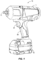
- FIG. 1 illustrates a power tool 10 (e.g., an impact wrench) including a housing 14, an electric motor (e.g., a brushless electric motor 16; FIG. 9 ) disposed within the housing 14, and an output shaft which, either directly or indirectly, performs work on a workpiece during operation of the tool 10.
- the output shaft is configured as an anvil 18 having a square drive for attachment to a corresponding size socket.
- the output shaft may include a different configuration or may include a conventional chuck for receipt of any of a number of different tool bits.
- the power tool 10 may be configured as a non-impact rotary tool (e.g., a drill or screwdriver) or a non-rotary power tool.
- the power tool 10 also includes a trigger assembly 22 for activating and deactivating the motor 16.
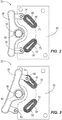
- the trigger assembly 22 includes a trigger 26 pivotably coupled to the housing 14 by a pivot 30, first and second conductors 34, 38 (e.g., pieces of ferrous or non-ferrous metal) supported by the trigger 26 on opposite sides of the pivot 30, and a torsion spring 40 for biasing the trigger 26 toward a neutral or "home" position (shown in FIG. 2 ).
- the trigger assembly 22 also includes a printed circuit board (“PCB") 42 having thereon first and second inductive sensors 46, 50, which are also components of a control system 54 shown in FIG. 9 .
- the PCB 42 is positioned in close proximity to the trigger 26 in a grip portion 58 of the housing 14 ( FIG. 1 ).
- a power source such as a battery 62, provides power to the PCB 42 and the motor 16 when activated by the trigger assembly 22.
- the first and second inductive sensors 46, 50 are configured as coil traces on the PCB 42.
- an AC voltage is applied to each of the sensors, 46, 50, an electromagnetic field is created.
- a voltage will be induced in the conductors 34, 38 in response to relative movement between the conductors 34, 38 and the magnetic fields of the respective inductive sensors 46, 50 which, in turn, produces Eddy currents in the conductors 34, 38 that oppose the electromagnetic fields created by the respective inductive sensors 46, 50.
- This changes the inductance of the inductive sensors 46, 50 which can be measured and used as an indicator of the presence or physical proximity of the conductors 34, 38 relative to the sensors 46, 50.
- each of the inductive sensors 46, 50 is configured as an LC tank circuit, the frequency of which (hereinafter, the "sensor frequency”) changes in response to a change in inductance.
- each of the inductive sensors 46, 50 is elongated and has a uniform number or density of windings throughout the length of the sensors 46, 50 between a proximal end 66 and a distal end 70 of each of the sensors 46, 50.
- the measured change in inductance of the sensors 46, 50 in response to movement of the conductors 34, 38 relative to the sensors 46, 50 can be used to activate the motor 16 for rotation at a constant speed in either a forward or reverse direction, depending upon which direction the trigger 26 is pivoted.
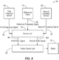
- the control system 54 also includes a reference clock 74, which is also configured as an LC tank circuit. However, the reference clock 74 is isolated from the conductors 34, 38 and therefore is operable to output a constant reference frequency, the purpose of which is described in detail below.
- the control system 54 also includes a sensor unit 78, which receives the output of the inductive sensors 46, 50 and the reference clock 74, and a motor control unit (“MCU") 82 electrically coupled to the motor 16.
- the sensor unit 78 continuously receives a first frequency signal 86 indicative of the sensor frequency of the first inductive sensor 46, a second frequency signal 90 indicative of the sensor frequency of the second inductive sensor 50, and a reference frequency signal 94 indicative of the reference frequency of the reference clock 74.
- the sensor unit 78 is operable to calculate a frequency ratio, which is a ratio of the sensor frequency to the reference frequency. Specifically, the sensor unit 78 calculates a first frequency ratio and a second frequency ratio, and digitally outputs a first ratio signal 98 indicative of the first frequency ratio and a second ratio signal 102 indicative of the second frequency ratio to the MCU 82.
- the MCU 82 is operable to interpolate the first and second ratio signals 98, 102 to determine whether the trigger 26 has been depressed and in which direction (e.g., clockwise about the pivot 30 or counter-clockwise).
- the MCU 82 associates this situation with the trigger 26 being pivoted in a clockwise direction from the neutral position shown in FIG. 2 toward the position shown in FIG. 3 , coinciding with the first conductor 34 moving over the first inductive sensor 46. Furthermore, the MCU 82 associates pivoting the trigger 26 in a clockwise direction with activating the motor 16 in a forward direction at a constant and predetermined speed.
- an expected initial value e.g., a ratio of 1: 1
- the MCU 82 associates this situation with the trigger 26 being pivoted in a clockwise direction from the neutral position shown in FIG. 2 toward the position shown in FIG. 3 , coinciding with the first conductor 34 moving over the first inductive sensor 46.
- the MCU 82 associates pivoting the trigger 26 in a clockwise direction with activating the motor 16 in a forward direction at a constant and predetermined speed.
- the MCU 82 associates this situation with the trigger 26 being pivoted in a counter-clockwise direction from the neutral position shown in FIG. 2 toward the position shown in FIG. 4 , coinciding with the second conductor 38 moving over the second inductive sensor 50. Furthermore, the MCU 82 associates pivoting the trigger 26 in a counter-clockwise direction with activating the motor 16 in a reverse direction at a constant and predetermined speed.
- an expected initial value e.g., a ratio of 1:1
- This action again causes a change in the sensor frequency of the first inductive sensor 46, which is interpolated by the MCU 82 (as a result of the first ratio signal 98 deviating from an initial value) as the trigger 26 returning to the neutral position. Thereafter, the MCU 82 deactivates the motor 16, thus stopping forward rotation of the anvil 18.
- the operator pivots the trigger 26 from the neutral position shown in FIG. 2 to the position shown in FIG. 4 , causing the second conductor 38 to move over the second inductive sensor 50.
- this change is detected by the MCU 82, which then activates the motor 16 in a reverse direction at a constant speed.
- the operator releases the trigger 26 it is returned to the neutral position shown in FIG. 2 by the torsion spring, again causing the second conductor 38 to move over the second inductive sensor 50.
- This action again causes a change in the sensor frequency of the second inductive sensor 50, which is interpolated by the MCU 82 (as a result of the second ratio signal 102 deviating from an initial value) as the trigger 26 returning to the neutral position. Thereafter, the MCU 82 deactivates the motor 16, thus stopping reverse rotation of the anvil 18.
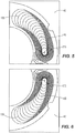
- the uniform inductive sensors 46, 50 shown in FIGS. 2-4 may be replaced with inductive sensors 146, 150 having a non-uniform winding density along the length of the inductive sensors 146, 150 ( FIGS. 5 and 6 ).
- each of the inductive sensors 146, 150 includes a relatively low winding density at a proximal end 166 of the sensors 146, 150 (i.e., an end closest to the respective conductors 34, 38 when the trigger 26 is in the neutral position) and a relatively high winding density at a distal end 170 of the sensors 146, 150 (i.e., an end farthest from the respective conductors 34, 38 when the trigger 26 is in the neutral position).
- the MCU 82 is also operable to control the speed at which the motor 16 operates in proportion to the degree to which the trigger 26 is pivoted.
- the operator pivots the trigger 26 from the neutral position shown in FIG. 2 in a clockwise direction, causing the first conductor 34 to move over the first inductive sensor 146.
- the first ratio signal changing between an expected initial value (e.g., 1:1) and an alternate value (e.g., one greater than or less than 1:1) as is the case when using the inductive sensors 46, 50 of FIG.
- the first ratio signal input 98 to the MCU 82 continuously changes from the initial value (e.g., 1:1) to a final (e.g., a maximum or minimum) value coinciding with placement of the first conductor 34 above the distal end 170 of the first inductive sensor 146.
- This change is detected by the MCU 82 which, depending upon the degree to which the trigger 26 is pivoted in the clockwise direction, activates the motor 16 in a forward direction at a rotational speed that is proportional to the degree to which the trigger 26 is pivoted.
- the MCU 82 will continue to drive the motor 16 at a constant rotational speed proportional to the degree to which the trigger 26 is initially pivoted, until the trigger 26 is either depressed to pivot the trigger 26 further in a clockwise direction (to thereby accelerate the motor 16 to a higher speed) or released to deactivate the motor 16. If the trigger 26 is further pivoted in the clockwise direction, the first conductor 34 is moved further along the length of the first inductive sensor 146, closer to the distal end 170 of the first inductive sensor 146.
- This action again causes a change in the sensor frequency of the first inductive sensor 146, with the magnitude of the first ratio signal 98 moving further from the initial value (e.g., 1:1) and toward the final (e.g., a maximum or minimum) value, prompting the MCU 82 to accelerate the motor 16 to a rotational speed proportional with the degree to which the trigger 26 is pivoted in the clockwise direction.
- the MCU 82 is also operable to drive the motor 16 at a variable rotational speed as described above, but in a reverse direction, in response to the trigger 26 being pivoted in a counter-clockwise direction from the neutral position shown in FIG. 2 .
- FIG. 7 illustrates a trigger assembly in accordance with another embodiment of the invention, with like features being shown with like reference numerals.
- the trigger assembly is similar to that described above using the inductive sensors 146, 150 shown in FIGS. 5 and 6 , but the second conductor 38 and the second inductive sensor 150 are omitted.
- the first conductor 34 is located approximately between the proximal and distal ends 166, 170 of the first (and only) inductive sensor 146.
- the MCU 82 is programmed to activate and drive the motor 16 in a forward direction at a rotational speed proportional to the degree to which the trigger 26 is pivoted in a clockwise direction from the neutral position, which further displaces the first conductor 34 toward the distal end 170 of the first inductive sensor 146.
- the MCU 82 is programmed to activate and drive the motor 16 in a reverse direction at a rotational speed proportional to the degree to which the trigger 26 is pivoted in a counter-clockwise direction from the neutral position, which further displaces the first conductor 34 toward the proximal end 166 of the first inductive sensor 146.
- a trigger assembly 322 in accordance with yet another embodiment of the invention is shown in FIG. 8 .
- a slidable trigger 326 supporting a conductor 334 thereon is employed.
- the slidable trigger 326 is biased by a spring to a neutral position spaced from a single, linear inductive sensor 346 having a non-uniform winding density.
- a separate direction switch (not shown) on the housing 14 of the power tool 10 is employed to toggle rotation of the motor 16 between forward and reverse directions.
- the MCU 82 is programmed to increase the rotational speed of the motor 16 as the slidable trigger 326 slides over the inductive sensor 346 as the conductor 334 approaches the distal end 370 of the inductive sensor 346.
- the MCU 82 is programmed to decrease the rotational speed of the motor 16 as the slidable trigger 326 slides over the inductive sensor 346 in an opposite direction as the conductor 334 approaches the proximal end 366 of the inductive sensor 346.
- the MCU 82 is programmed to hold the rotational speed of the motor 16 at a constant value if the slidable trigger 326 stops anywhere between the proximal and distal ends 366, 370 of the inductive sensor 346.
- the trigger assemblies of FIGS. 2-7 allow the motor 16 to be controlled without a secondary direction switch to otherwise toggle the motor 16 between forward and reverse rotational directions, thus reducing the number of components required to manufacture the tool 10 and the attendant cost. Also, because the inductive sensors 46, 50, 146, 150, 346 function as noncontact switches, the trigger assemblies 22, 322 disclosed herein are expected to have greater longevity than a traditional contact-based trigger switch, which can wear over time.
Landscapes
- Engineering & Computer Science (AREA)
- Power Engineering (AREA)
- Physics & Mathematics (AREA)
- General Physics & Mathematics (AREA)
- Microelectronics & Electronic Packaging (AREA)
- Mechanical Engineering (AREA)
- Control Of Ac Motors In General (AREA)
- Portable Power Tools In General (AREA)
Abstract
Description
- This application claims priority to
U.S. Provisional Patent Application No. 62/400,707 filed on September 28, 2016 - The present invention relates to power tools, and more particularly to trigger assemblies for power tools.
- Power tools have triggers that allow operators to activate the working element of the power tool when the working element is applied to an object. Depending on the type of power tool, triggers may be used to rotate, extend, retract, oscillate, reciprocate, speed up, and slow down the working element. Some triggers may allow an operator to cause the working element to perform more than one of these functions at the same time. Power tools may also include multiple triggers that are separately dedicated to these different functions.
- The present invention provides, in one aspect, a trigger assembly for use with a power tool having an electric motor. The trigger assembly includes a trigger, a conductor coupled for movement with the trigger, and a printed circuit board. The printed circuit board has an inductive sensor thereon responsive to relative movement between the conductor and the inductive sensor caused by movement of the trigger, the inductive sensor being a coil trace having a proximal end located proximate the trigger and a distal end, wherein the distal end has a different winding density than the proximal end. An output of the inductive sensor is used to activate the electric motor.
- In response to the conductor moving away from the proximal end of the inductive sensor and towards the distal end, a rotational speed of the motor may be accelerated, and wherein in response to the conductor moving away from the distal end of the inductive sensor and towards the proximal end, the rotational speed of the motor may be decelerated.
- The trigger assembly may further comprise a spring biasing the trigger toward a neutral position in which the conductor is closer to the proximal end than the distal end.
- The coil trace may be linear.
- The coil trace may be curvilinear,
- The conductor may be a first conductor, the coil trace may be a first coil trace, and the output may be a first output used to active the motor in a first rotational direction. The trigger assembly may further comprise, a second conductor coupled for movement with the trigger, and a second inductive sensor configured as a second coil trace on the printed circuit board having a proximal end located proximate the trigger and a distal end, wherein the distal end of the second coil trace has a different winding density than the proximal end of the second coil trace. Wherein the second inductive sensor may be responsive to relative movement between the second conductor and the second inductive sensor caused by movement of the trigger, and wherein a second output of the second inductive sensor may be used to activate the motor in a second rotational direction that is different than the first rotational direction. Wherein, in response to the second conductor moving away from the proximal end of the second coil trace and towards the distal end of the second coil trace, a rotational speed of the electric motor is accelerated, and wherein in response to the second conductor moving away from the distal end of the second coil trace and towards the proximal end of the second coil trace, the rotational speed of the motor is decelerated
- The present invention provides, in another aspect, a power tool having an electric motor, a controller in electrical communication with the motor to activate and deactivate the motor, a trigger, a conductor coupled for movement with the trigger, and a printed circuit board. The printed circuit board has an inductive sensor thereon responsive to relative movement between the conductor and the inductive sensor caused by movement of the trigger, the inductive sensor being a coil trace having a proximal end located proximate the trigger and distal end, wherein the distal end has a different winding density than the proximal end. An output of the inductive sensor is detected by the controller, which in response activates or deactivates the electric motor.
- In response to the conductor moving away from the proximal end of the inductive sensor and towards the distal end, a rotational speed of the motor may be accelerated by the controller, and wherein, in response to the conductor moving away from the distal end of the inductive sensor and towards the proximal end, the rotational speed of the motor may be decelerated by the controller.
- The power tool may further comprise a spring biasing the trigger toward a neutral position in which the conductor is closer to the proximal end than the distal end.
- The conductor may be a first conductor, the coil trace may be a first coil trace, and the output may be a first output detected by the controller to activate the motor in a first rotational direction, and wherein the power tool may further comprise, a second conductor coupled for movement with the trigger, and a second inductive sensor configured as a second coil trace on the printed circuit board having a proximal end located proximate the trigger and a distal end, wherein the distal end of the second coil trace has a different winding density than the proximal end of the second coil trace. The second inductive sensor may be responsive to relative movement between the second conductor and the second inductive sensor caused by movement of the trigger, and wherein a second output of the second inductive sensor may be detected by the controller, which in response activates the motor in a second rotational direction that is different than the first rotational direction. Further, in response to the second conductor moving away from the proximal end of the second coil trace and towards the distal end of the second coil trace, a rotational speed of the electric motor may be accelerated by the controller, and wherein in response to the second conductor moving away from the distal end of the second coil trace and towards the proximal end of the second coil trace, the rotational speed of the motor may be decelerated by the controller.
- The power tool may further comprise a sensor unit in communication with the controller; and a reference clock configured to provide a reference frequency signal to the sensor unit that is indicative of a reference frequency of the reference clock, wherein the output of the inductive sensor is a sensor frequency signal indicative of a sensor frequency of the inductive sensor, wherein the sensor frequency of the inductive sensor is configured to change based on relative movement between the conductor and the inductive sensor, and wherein the sensor unit is configured to receive the sensor frequency signal from the inductive sensor and output a ratio signal to the controller, which is a ratio of the sensor frequency to the reference frequency, and wherein the controller activates or deactivates the motor based upon the ratio signal.
- The controller may be configured to activate the motor in one of a first rotational direction or an opposite, second rotational direction in response to a change in the first ratio signal.
- The present invention provides, in yet another aspect, a method of operating a power tool. The method includes pressing a trigger in a first direction, moving a conductor over an inductive sensor, the inductive sensor being a coil trace having a proximal end located proximate the trigger and a distal end, the distal end having a different winding density than the proximal end, moving the conductor away from the proximal end of the inductive sensor and towards the distal end of the inductive sensor, outputting a signal from the inductive sensor, and accelerating the rotational speed of a motor as the conductor is moved from the proximal end of the inductive sensor towards the distal end..
- Wherein the method may further comprise releasing the trigger, biasing the trigger in a second direction that is opposite the first direction, moving the conductor away from the distal end of the inductive sensor and towards the proximal end of the inductive sensor, and decelerating the rotational speed of the motor as the conductor is moved from the distal end of the inductive sensor to towards the proximal end.
- Wherein pressing the trigger in the first direction may comprise pivoting the trigger in a first pivotal direction, such that the motor is activated in a first rotational direction, wherein the conductor is a first conductor and the inductive sensor is a first inductive sensor, and wherein the method may further comprise pivoting the trigger in a second pivotal direction that is opposite the first pivotal direction, moving a second conductor over a second inductive sensor, outputting a second signal from the second inductive sensor, and activating the electric motor in a second rotational direction that is different than the first rotational direction based on the second signal.
- Other features and aspects of the invention will become apparent by consideration of the following detailed description and accompanying drawings.
-
-
FIG. 1 is a perspective view of a power tool in which a trigger assembly of the invention may be incorporated. -
FIG. 2 is a plan view of a trigger assembly in accordance with an embodiment of the invention, with a trigger shown in a neutral position. -
FIG. 3 is a plan view of the trigger assembly ofFIG. 2 , illustrating the trigger rotating in a clockwise direction over a first inductive sensor. -
FIG. 4 is a plan view of the trigger assembly ofFIG. 2 , illustrating the trigger rotating in a counter-clockwise direction over a second inductive sensor. -
FIG. 5 is a plan view of an alternate configuration of the first inductive sensor shown inFIGS. 2-4 . -
FIG. 6 is a plan view of an alternate configuration of the second inductive sensor shown inFIG. 2-4 . -
FIG. 7 is a plan view of a trigger assembly, with portions removed for clarity, in accordance with another embodiment of the invention. -
FIG. 8 is a plan view of a trigger assembly in accordance with yet another embodiment of the invention. -
FIG. 9 is a flow diagram showing the electrical communication between the first and second inductive sensors of the trigger assembly, a reference clock, a sensor unit, and a motor control unit on a printed circuit board. - Before any embodiments of the invention are explained in detail, it is to be understood that the invention is not limited in its application to the details of construction and the arrangement of components set forth in the following description or illustrated in the following drawings. The invention is capable of other embodiments and of being practiced or of being carried out in various ways. Also, it is to be understood that the phraseology and terminology used herein is for the purpose of description and should not be regarded as limiting.
-
FIG. 1 illustrates a power tool 10 (e.g., an impact wrench) including ahousing 14, an electric motor (e.g., a brushlesselectric motor 16;FIG. 9 ) disposed within thehousing 14, and an output shaft which, either directly or indirectly, performs work on a workpiece during operation of thetool 10. In the illustrated embodiment, the output shaft is configured as ananvil 18 having a square drive for attachment to a corresponding size socket. However, the output shaft may include a different configuration or may include a conventional chuck for receipt of any of a number of different tool bits. Furthermore, thepower tool 10 may be configured as a non-impact rotary tool (e.g., a drill or screwdriver) or a non-rotary power tool. - With reference to
FIG. 2 , thepower tool 10 also includes atrigger assembly 22 for activating and deactivating themotor 16. Thetrigger assembly 22 includes atrigger 26 pivotably coupled to thehousing 14 by apivot 30, first andsecond conductors 34, 38 (e.g., pieces of ferrous or non-ferrous metal) supported by thetrigger 26 on opposite sides of thepivot 30, and atorsion spring 40 for biasing thetrigger 26 toward a neutral or "home" position (shown inFIG. 2 ). Thetrigger assembly 22 also includes a printed circuit board ("PCB") 42 having thereon first and secondinductive sensors control system 54 shown inFIG. 9 . The PCB 42 is positioned in close proximity to thetrigger 26 in agrip portion 58 of the housing 14 (FIG. 1 ). A power source, such as abattery 62, provides power to thePCB 42 and themotor 16 when activated by thetrigger assembly 22. - With reference to
FIG. 2 , the first and secondinductive sensors PCB 42. When an AC voltage is applied to each of the sensors, 46, 50, an electromagnetic field is created. Based on Faraday's Law of Induction, a voltage will be induced in theconductors conductors inductive sensors conductors inductive sensors inductive sensors conductors sensors FIG. 9 , each of theinductive sensors - As shown in
FIG. 2 , each of theinductive sensors sensors proximal end 66 and adistal end 70 of each of thesensors trigger assembly 22, the measured change in inductance of thesensors conductors sensors motor 16 for rotation at a constant speed in either a forward or reverse direction, depending upon which direction thetrigger 26 is pivoted. - As shown in
FIG. 9 , thecontrol system 54 also includes areference clock 74, which is also configured as an LC tank circuit. However, thereference clock 74 is isolated from theconductors control system 54 also includes asensor unit 78, which receives the output of theinductive sensors reference clock 74, and a motor control unit ("MCU") 82 electrically coupled to themotor 16. Thesensor unit 78 continuously receives afirst frequency signal 86 indicative of the sensor frequency of the firstinductive sensor 46, asecond frequency signal 90 indicative of the sensor frequency of the secondinductive sensor 50, and areference frequency signal 94 indicative of the reference frequency of thereference clock 74. - Using the sensor frequency signals 86, 90 and the
reference frequency signal 94 as inputs, thesensor unit 78 is operable to calculate a frequency ratio, which is a ratio of the sensor frequency to the reference frequency. Specifically, thesensor unit 78 calculates a first frequency ratio and a second frequency ratio, and digitally outputs afirst ratio signal 98 indicative of the first frequency ratio and asecond ratio signal 102 indicative of the second frequency ratio to theMCU 82. TheMCU 82 is operable to interpolate the first and second ratio signals 98, 102 to determine whether thetrigger 26 has been depressed and in which direction (e.g., clockwise about thepivot 30 or counter-clockwise). Specifically, if thefirst ratio signal 98 deviates from an expected initial value (e.g., a ratio of 1: 1) while thesecond ratio signal 102 remains unchanged, theMCU 82 associates this situation with thetrigger 26 being pivoted in a clockwise direction from the neutral position shown inFIG. 2 toward the position shown inFIG. 3 , coinciding with thefirst conductor 34 moving over the firstinductive sensor 46. Furthermore, theMCU 82 associates pivoting thetrigger 26 in a clockwise direction with activating themotor 16 in a forward direction at a constant and predetermined speed. Likewise, if thesecond ratio signal 102 deviates from an expected initial value (e.g., a ratio of 1:1) while thefirst ratio signal 98 remains unchanged, theMCU 82 associates this situation with thetrigger 26 being pivoted in a counter-clockwise direction from the neutral position shown inFIG. 2 toward the position shown inFIG. 4 , coinciding with thesecond conductor 38 moving over the secondinductive sensor 50. Furthermore, theMCU 82 associates pivoting thetrigger 26 in a counter-clockwise direction with activating themotor 16 in a reverse direction at a constant and predetermined speed. - In operation of the
power tool 10 using the embodiment of thetrigger assembly 22 shown inFIGS. 2-4 , to activate themotor 16 in a forward direction, the operator pivots thetrigger 26 from the neutral position shown inFIG. 2 to the position shown inFIG. 3 , causing thefirst conductor 34 to move over the firstinductive sensor 46. This changes the inductance of the firstinductive sensor 46, which in turn also causes the sensor frequency of the firstinductive sensor 46 to change. As described above, this change is detected by theMCU 82, which then activates themotor 16 in a forward direction at a constant speed. When the operator releases the trigger, it is returned to the neutral position shown inFIG. 2 by the torsion spring, again causing thefirst conductor 34 to move over the firstinductive sensor 46. This action again causes a change in the sensor frequency of the firstinductive sensor 46, which is interpolated by the MCU 82 (as a result of thefirst ratio signal 98 deviating from an initial value) as thetrigger 26 returning to the neutral position. Thereafter, theMCU 82 deactivates themotor 16, thus stopping forward rotation of theanvil 18. - Likewise, to activate the
motor 16 in a reverse direction, the operator pivots thetrigger 26 from the neutral position shown inFIG. 2 to the position shown inFIG. 4 , causing thesecond conductor 38 to move over the secondinductive sensor 50. This changes the inductance of the secondinductive sensor 50, which in turn also causes the sensor frequency of the secondinductive sensor 50 to change. As described above, this change is detected by theMCU 82, which then activates themotor 16 in a reverse direction at a constant speed. When the operator releases thetrigger 26, it is returned to the neutral position shown inFIG. 2 by the torsion spring, again causing thesecond conductor 38 to move over the secondinductive sensor 50. This action again causes a change in the sensor frequency of the secondinductive sensor 50, which is interpolated by the MCU 82 (as a result of thesecond ratio signal 102 deviating from an initial value) as thetrigger 26 returning to the neutral position. Thereafter, theMCU 82 deactivates themotor 16, thus stopping reverse rotation of theanvil 18. - In another embodiment of the trigger assembly (with like features being identified with like reference numerals), the uniform
inductive sensors FIGS. 2-4 may be replaced withinductive sensors inductive sensors 146, 150 (FIGS. 5 and 6 ). In other words, each of theinductive sensors proximal end 166 of thesensors 146, 150 (i.e., an end closest to therespective conductors trigger 26 is in the neutral position) and a relatively high winding density at adistal end 170 of thesensors 146, 150 (i.e., an end farthest from therespective conductors trigger 26 is in the neutral position). In this embodiment of the trigger assembly, theMCU 82 is also operable to control the speed at which themotor 16 operates in proportion to the degree to which thetrigger 26 is pivoted. - In operation of the
power tool 10 using the embodiment of the trigger assembly with theinductive sensors FIGS. 5 and 6 , to activate themotor 16 in a forward direction, the operator pivots thetrigger 26 from the neutral position shown inFIG. 2 in a clockwise direction, causing thefirst conductor 34 to move over the firstinductive sensor 146. This changes the inductance of the firstinductive sensor 146, which in turn also causes the sensor frequency of the firstinductive sensor 146 to change. However, rather than the first ratio signal changing between an expected initial value (e.g., 1:1) and an alternate value (e.g., one greater than or less than 1:1) as is the case when using theinductive sensors FIG. 2 having a uniform winding density, the firstratio signal input 98 to theMCU 82 continuously changes from the initial value (e.g., 1:1) to a final (e.g., a maximum or minimum) value coinciding with placement of thefirst conductor 34 above thedistal end 170 of the firstinductive sensor 146. This change is detected by theMCU 82 which, depending upon the degree to which thetrigger 26 is pivoted in the clockwise direction, activates themotor 16 in a forward direction at a rotational speed that is proportional to the degree to which thetrigger 26 is pivoted. - If the
trigger 26 is pivoted to an intermediate position and then held stationary, theMCU 82 will continue to drive themotor 16 at a constant rotational speed proportional to the degree to which thetrigger 26 is initially pivoted, until thetrigger 26 is either depressed to pivot thetrigger 26 further in a clockwise direction (to thereby accelerate themotor 16 to a higher speed) or released to deactivate themotor 16. If thetrigger 26 is further pivoted in the clockwise direction, thefirst conductor 34 is moved further along the length of the firstinductive sensor 146, closer to thedistal end 170 of the firstinductive sensor 146. This action again causes a change in the sensor frequency of the firstinductive sensor 146, with the magnitude of thefirst ratio signal 98 moving further from the initial value (e.g., 1:1) and toward the final (e.g., a maximum or minimum) value, prompting theMCU 82 to accelerate themotor 16 to a rotational speed proportional with the degree to which thetrigger 26 is pivoted in the clockwise direction. TheMCU 82 is also operable to drive themotor 16 at a variable rotational speed as described above, but in a reverse direction, in response to thetrigger 26 being pivoted in a counter-clockwise direction from the neutral position shown inFIG. 2 . -
FIG. 7 illustrates a trigger assembly in accordance with another embodiment of the invention, with like features being shown with like reference numerals. The trigger assembly is similar to that described above using theinductive sensors FIGS. 5 and 6 , but thesecond conductor 38 and the secondinductive sensor 150 are omitted. And, in the neutral position of thetrigger 26, thefirst conductor 34 is located approximately between the proximal anddistal ends inductive sensor 146. - In this embodiment, the
MCU 82 is programmed to activate and drive themotor 16 in a forward direction at a rotational speed proportional to the degree to which thetrigger 26 is pivoted in a clockwise direction from the neutral position, which further displaces thefirst conductor 34 toward thedistal end 170 of the firstinductive sensor 146. Likewise, theMCU 82 is programmed to activate and drive themotor 16 in a reverse direction at a rotational speed proportional to the degree to which thetrigger 26 is pivoted in a counter-clockwise direction from the neutral position, which further displaces thefirst conductor 34 toward theproximal end 166 of the firstinductive sensor 146. When the operator releases thetrigger 26, it is returned to its neutral position by the torsion spring, again causing thefirst conductor 34 to move over the firstinductive sensor 146. This action again causes a change in the sensor frequency of the firstinductive sensor 146, which is interpolated by theMCU 82 as the trigger returning to the neutral position (coinciding with placement of thefirst conductor 34 approximately between the proximal anddistal ends MCU 82 deactivates themotor 16, thus stopping rotation of theanvil 18. - A
trigger assembly 322 in accordance with yet another embodiment of the invention is shown inFIG. 8 . In this embodiment, aslidable trigger 326 supporting aconductor 334 thereon is employed. Theslidable trigger 326 is biased by a spring to a neutral position spaced from a single, linearinductive sensor 346 having a non-uniform winding density. In this embodiment, a separate direction switch (not shown) on thehousing 14 of thepower tool 10 is employed to toggle rotation of themotor 16 between forward and reverse directions. In the same manner as described above, theMCU 82 is programmed to increase the rotational speed of themotor 16 as theslidable trigger 326 slides over theinductive sensor 346 as theconductor 334 approaches thedistal end 370 of theinductive sensor 346. Likewise, theMCU 82 is programmed to decrease the rotational speed of themotor 16 as theslidable trigger 326 slides over theinductive sensor 346 in an opposite direction as theconductor 334 approaches theproximal end 366 of theinductive sensor 346. And, theMCU 82 is programmed to hold the rotational speed of themotor 16 at a constant value if theslidable trigger 326 stops anywhere between the proximal anddistal ends inductive sensor 346. - The trigger assemblies of
FIGS. 2-7 allow themotor 16 to be controlled without a secondary direction switch to otherwise toggle themotor 16 between forward and reverse rotational directions, thus reducing the number of components required to manufacture thetool 10 and the attendant cost. Also, because theinductive sensors trigger assemblies - The invention may be further defined by the following numbered clauses:
- 1. A trigger assembly for use with a power tool having an electric motor, the trigger assembly comprising:
- a trigger;
- a conductor coupled for movement with the trigger;
- a printed circuit board having an inductive sensor thereon responsive to relative movement between the conductor and the inductive sensor caused by movement of the trigger,
- wherein an output of the inductive sensor is used to activate the electric motor.
- 2. The trigger assembly of clause 1, wherein the inductive sensor is first inductive sensor, the conductor is a first conductor, and the output is a first output, and wherein the trigger assembly further comprises
a second conductor coupled for movement with the trigger, and
a second inductive sensor on the printed circuit board responsive to relative movement between the second conductor and the second inductive sensor caused by movement of the trigger, wherein a second output of the second inductive sensor is used to activate the electric motor. - 3. The trigger assembly of clause 2, wherein the first output of the first inductive sensor is used to activate the electric motor in a first rotational direction, and wherein the second output of the second inductive sensor is used to activate the electric motor in a second rotational direction that is different than the first rotational direction.
- 4. The trigger assembly of clause 1, wherein the inductive sensor is a coil trace having a proximal end located proximate the trigger and a distal end, and wherein the distal end has a different winding density than the proximal end.
- 5. The trigger assembly of clause 4, wherein, in response to the conductor moving away from the proximal end of the inductive sensor and towards the distal end, a rotational speed of the motor is accelerated, and wherein in response to the conductor moving away from the distal end of the inductive sensor and towards the proximal end, the rotational speed of the motor is decelerated.
- 6. The trigger assembly of clause 5, further comprising a spring biasing the trigger toward a neutral position in which the conductor is closer to the proximal end than the distal end.
- 7. The trigger assembly of clause 6, wherein the coil trace is linear.
- 8. The trigger assembly of clause 6, wherein the coil trace is curvilinear.
- 9. The trigger assembly of clause 8, wherein the conductor is a first conductor, the coil trace is a first coil trace, and the output is a first output used to activate the motor in a first rotational direction, and wherein the trigger assembly further comprises
a second conductor coupled for movement with the trigger, and
a second inductive sensor configured as a second coil trace on the printed circuit board having a proximal end located proximate the trigger and a distal end, wherein the distal end of the second coil trace has a different winding density than the proximal end of the second coil trace,
wherein the second inductive sensor is responsive to relative movement between the second conductor and the second inductive sensor caused by movement of the trigger, and wherein a second output of the second inductive sensor is used to activate the motor in a second rotational direction that is different than the first rotational direction,
wherein, in response to the second conductor moving away from the proximal end of the second coil trace and towards the distal end of the second coil trace, a rotational speed of the electric motor is accelerated, and wherein in response to the second conductor moving away from the distal end of the second coil trace and towards the proximal end of the second coil trace, the rotational speed of the motor is decelerated. - 10. The trigger assembly of clause 1, wherein the inductive sensor is a coil trace having a first end and a second end that has a different coil density than the first end, and wherein the trigger assembly further comprises
a spring biasing the trigger to a position in which the conductor is located in a neutral position between the first end and the second end,
wherein, in response to the conductor moving away from the neutral position and towards the first end of the coil trace, the output of the inductive sensor is used to activate the motor in a first rotational direction and to accelerate a rotational speed of the motor, and
wherein, in response to the conductor moving away from the neutral position and towards the second end of the coil trace, the output of the inductive sensor is used to activate the motor in an opposite, second rotational direction and to accelerate a rotational speed of the motor. - 11. A power tool comprising:
- an electric motor;
- a controller in electrical communication with the motor to activate and deactivate the motor;
- a trigger;
- a conductor coupled for movement with the trigger; and
- a printed circuit board having an inductive sensor thereon responsive to relative movement between the conductor and the inductive sensor caused by movement of the trigger;
- wherein an output of the inductive sensor is detected by the controller, which in response activates or deactivates the electric motor.
- 12. The power tool of clause 11, wherein the inductive sensor is first inductive sensor, the conductor is a first conductor, and the output is a first output, and wherein the power tool further comprises
a second conductor coupled for movement with the trigger, and
a second inductive sensor on the printed circuit board responsive to relative movement between the second conductor and the second inductive sensor caused by movement of the trigger, wherein a second output of the second inductive sensor is detected by the controller, which in response activates the electric motor. - 13. The power tool of clause 12, wherein the first output of the first inductive sensor is detected by the controller, which in response activates the electric motor in a first rotational direction, and wherein the second output of the second inductive sensor is detected by the controller, which in response activates the electric motor in a second rotational direction that is different than the first rotational direction.
- 14. The power tool of clause 11, wherein the inductive sensor is a coil trace having a proximal end located proximate the trigger and a distal end, and wherein the distal end has a different winding density than the proximal end.
- 15. The power tool of
clause 14, wherein, in response to the conductor moving away from the proximal end of the inductive sensor and towards the distal end, a rotational speed of the motor is accelerated by the controller, and wherein, in response to the conductor moving away from the distal end of the inductive sensor and towards the proximal end, the rotational speed of the motor is decelerated by the controller. - 16. The power tool of clause 15, further comprising a spring biasing the trigger toward a neutral position in which the conductor is closer to the proximal end than the distal end.
- 17. The power tool of
clause 16, wherein the conductor is a first conductor, the coil trace is a first coil trace, and the output is a first output detected by the controller to activate the motor in a first rotational direction, and wherein the power tool further comprises
a second conductor coupled for movement with the trigger, and
a second inductive sensor configured as a second coil trace on the printed circuit board having a proximal end located proximate the trigger and a distal end, wherein the distal end of the second coil trace has a different winding density than the proximal end of the second coil trace,
wherein the second inductive sensor is responsive to relative movement between the second conductor and the second inductive sensor caused by movement of the trigger, and wherein a second output of the second inductive sensor is detected by the controller, which in response activates the motor in a second rotational direction that is different than the first rotational direction,
wherein, in response to the second conductor moving away from the proximal end of the second coil trace and towards the distal end of the second coil trace, a rotational speed of the electric motor is accelerated by the controller, and wherein in response to the second conductor moving away from the distal end of the second coil trace and towards the proximal end of the second coil trace, the rotational speed of the motor is decelerated by the controller. - 18. The power tool of clause 11, wherein the inductive sensor is a coil trace having a first end and a second end that has a different coil density than the first end, and wherein the power tool further comprises
a spring biasing the trigger to a position in which the conductor is located in a neutral position between the first end and the second end,
wherein, in response to the conductor moving away from the neutral position and towards the first end of the coil trace, the output of the inductive sensor is detected by the controller, which in response activates the motor in a first rotational direction and accelerates a rotational speed of the motor, and
wherein, in response to the conductor moving away from the neutral position and towards the second end of the coil trace, the output of the inductive sensor is detected by the controller, which in response activates the motor in an opposite, second rotational direction and accelerates the rotational speed of the motor. - 19. The power tool of clause 11, further comprising:
- a sensor unit in communication with the controller; and
- a reference clock configured to provide a reference frequency signal to the sensor unit that is indicative of a reference frequency of the reference clock,
- wherein the output of the inductive sensor is a sensor frequency signal indicative of a sensor frequency of the inductive sensor, wherein the sensor frequency of the inductive sensor is configured to change based on relative movement between the conductor and the inductive sensor,
- wherein the sensor unit is configured to receive the sensor frequency signal from the inductive sensor and output a ratio signal to the controller, which is a ratio of the sensor frequency to the reference frequency, and wherein the controller activates or deactivates the motor based upon the ratio signal.
- 20. The power tool of clause 19, wherein the controller is configured to activate the motor in one of a first rotational direction or an opposite, second rotational direction in response to a change in the first ratio signal.
- 21. A method of operating a power tool, the method comprising:
- pressing a trigger in a first direction;
- moving a conductor over an inductive sensor;
- outputting a signal from the inductive sensor; and
- activating an electric motor based on the signal.
- 22. The method of clause 21, wherein the inductive sensor is a coil trace having a proximal end located proximate the trigger and a distal end, and wherein the distal end has a different winding density than the proximal end, and wherein the method further comprises:
- moving the conductor away from the proximal end of the inductive sensor and towards the distal end of the inductive sensor; and
- accelerating the rotational speed of the motor as the conductor is moved from the proximal end of the inductive sensor towards the distal end.
- 23. The method of
clause 22, further comprising:- releasing the trigger;
- biasing the trigger in a second direction that is opposite the first direction;
- moving the conductor away from the distal end of the inductive sensor and towards the proximal end of the inductive sensor; and
- decelerating the rotational speed of the motor as the conductor is moved from the distal end of the inductive sensor to towards the proximal end.
- 24. The method of clause 21, wherein activating the electric motor comprises activating the electric motor in a first rotational direction.
- 25. The method of clause 24, wherein pressing the trigger in the first direction comprises pivoting the trigger in a first pivotal direction, wherein the conductor is a first conductor and the inductive sensor is a first inductive sensor, and wherein the method further comprises:
- pivoting the trigger in a second pivotal direction that is opposite the first pivotal direction;
- moving a second conductor over a second inductive sensor;
- outputting a second signal from the second inductive sensor; and
- activating the electric motor in a second rotational direction that is different than the first rotational direction based on the second signal.
- Various features of the invention are set forth in the following claims.
Claims (15)
- A trigger assembly for use with a power tool having an electric motor, the trigger assembly comprising:a trigger;a conductor coupled for movement with the trigger;a printed circuit board having an inductive sensor thereon responsive to relative movement between the conductor and the inductive sensor caused by movement of the trigger, the inductive sensor being a coil trace having a proximal end located proximate the trigger and a distal end,wherein the distal end has a different winding density than the proximal end, andwherein an output of the inductive sensor is used to activate the electric motor.
- The trigger assembly of claim 1, wherein, in response to the conductor moving away from the proximal end of the inductive sensor and towards the distal end, a rotational speed of the motor is accelerated, and wherein in response to the conductor moving away from the distal end of the inductive sensor and towards the proximal end, the rotational speed of the motor is decelerated.
- The trigger assembly of claim 2, further comprising a spring biasing the trigger toward a neutral position in which the conductor is closer to the proximal end than the distal end.
- The trigger assembly of claim 3, wherein the coil trace is linear.
- The trigger assembly of claim 3, wherein the coil trace is curvilinear.
- The trigger assembly of claim 5, wherein the conductor is a first conductor, the coil trace is a first coil trace, and the output is a first output used to activate the motor in a first rotational direction, and wherein the trigger assembly further comprises
a second conductor coupled for movement with the trigger, and
a second inductive sensor configured as a second coil trace on the printed circuit board having a proximal end located proximate the trigger and a distal end, wherein the distal end of the second coil trace has a different winding density than the proximal end of the second coil trace,
wherein the second inductive sensor is responsive to relative movement between the second conductor and the second inductive sensor caused by movement of the trigger, and wherein a second output of the second inductive sensor is used to activate the motor in a second rotational direction that is different than the first rotational direction,
wherein, in response to the second conductor moving away from the proximal end of the second coil trace and towards the distal end of the second coil trace, a rotational speed of the electric motor is accelerated, and wherein in response to the second conductor moving away from the distal end of the second coil trace and towards the proximal end of the second coil trace, the rotational speed of the motor is decelerated. - A power tool comprising:an electric motor;a controller in electrical communication with the motor to activate and deactivate the motor;a trigger;a conductor coupled for movement with the trigger; anda printed circuit board having an inductive sensor thereon responsive to relative movement between the conductor and the inductive sensor caused by movement of the trigger, the inductive sensor being a coil trace having a proximal end located proximate the trigger and a distal end;wherein the distal end has a different winding density than the proximal end, andwherein an output of the inductive sensor is detected by the controller, which in response activates or deactivates the electric motor.
- The power tool of claim 7, wherein, in response to the conductor moving away from the proximal end of the inductive sensor and towards the distal end, a rotational speed of the motor is accelerated by the controller, and wherein, in response to the conductor moving away from the distal end of the inductive sensor and towards the proximal end, the rotational speed of the motor is decelerated by the controller.
- The power tool of claim 8, further comprising a spring biasing the trigger toward a neutral position in which the conductor is closer to the proximal end than the distal end.
- The power tool of claim 9, wherein the conductor is a first conductor, the coil trace is a first coil trace, and the output is a first output detected by the controller to activate the motor in a first rotational direction, and wherein the power tool further comprises
a second conductor coupled for movement with the trigger, and
a second inductive sensor configured as a second coil trace on the printed circuit board having a proximal end located proximate the trigger and a distal end, wherein the distal end of the second coil trace has a different winding density than the proximal end of the second coil trace,
wherein the second inductive sensor is responsive to relative movement between the second conductor and the second inductive sensor caused by movement of the trigger, and wherein a second output of the second inductive sensor is detected by the controller, which in response activates the motor in a second rotational direction that is different than the first rotational direction,
wherein, in response to the second conductor moving away from the proximal end of the second coil trace and towards the distal end of the second coil trace, a rotational speed of the electric motor is accelerated by the controller, and wherein in response to the second conductor moving away from the distal end of the second coil trace and towards the proximal end of the second coil trace, the rotational speed of the motor is decelerated by the controller. - The power tool of claim 7, further comprising:a sensor unit in communication with the controller; anda reference clock configured to provide a reference frequency signal to the sensor unit that is indicative of a reference frequency of the reference clock,wherein the output of the inductive sensor is a sensor frequency signal indicative of a sensor frequency of the inductive sensor, wherein the sensor frequency of the inductive sensor is configured to change based on relative movement between the conductor and the inductive sensor,wherein the sensor unit is configured to receive the sensor frequency signal from the inductive sensor and output a ratio signal to the controller, which is a ratio of the sensor frequency to the reference frequency, and wherein the controller activates or deactivates the motor based upon the ratio signal.
- The power tool of claim 11, wherein the controller is configured to activate the motor in one of a first rotational direction or an opposite, second rotational direction in response to a change in the first ratio signal.
- A method of operating a power tool, the method comprising:pressing a trigger in a first direction;moving a conductor over an inductive sensor, the inductive sensor being a coil trace having a proximal end located proximate the trigger and a distal end, the distal end having a different winding density than the proximal end;moving the conductor away from the proximal end of the inductive sensor and towards the distal end of the inductive sensor;outputting a signal from the inductive sensor; andaccelerating the rotational speed of a motor as the conductor is moved from the proximal end of the inductive sensor towards the distal end..
- The method of claim 13, further comprising:releasing the trigger;biasing the trigger in a second direction that is opposite the first direction;moving the conductor away from the distal end of the inductive sensor and towards the proximal end of the inductive sensor; anddecelerating the rotational speed of the motor as the conductor is moved from the distal end of the inductive sensor to towards the proximal end.
- The method of claim 13, wherein pressing the trigger in the first direction comprises pivoting the trigger in a first pivotal direction, such that the motor is activated in a first rotational direction, wherein the conductor is a first conductor and the inductive sensor is a first inductive sensor, and wherein the method further comprises:pivoting the trigger in a second pivotal direction that is opposite the first pivotal direction;moving a second conductor over a second inductive sensor;outputting a second signal from the second inductive sensor; andactivating the electric motor in a second rotational direction that is different than the first rotational direction based on the second signal.
Applications Claiming Priority (3)
| Application Number | Priority Date | Filing Date | Title |
|---|---|---|---|
| US201662400707P | 2016-09-28 | 2016-09-28 | |
| PCT/US2017/053215 WO2018063978A1 (en) | 2016-09-28 | 2017-09-25 | Trigger assembly |
| EP17857255.8A EP3484663B1 (en) | 2016-09-28 | 2017-09-25 | Trigger assembly |
Related Parent Applications (2)
| Application Number | Title | Priority Date | Filing Date |
|---|---|---|---|
| EP17857255.8A Division EP3484663B1 (en) | 2016-09-28 | 2017-09-25 | Trigger assembly |
| EP17857255.8A Division-Into EP3484663B1 (en) | 2016-09-28 | 2017-09-25 | Trigger assembly |
Publications (2)
| Publication Number | Publication Date |
|---|---|
| EP3763485A1 true EP3763485A1 (en) | 2021-01-13 |
| EP3763485B1 EP3763485B1 (en) | 2022-04-20 |
Family
ID=61685777
Family Applications (2)
| Application Number | Title | Priority Date | Filing Date |
|---|---|---|---|
| EP20192388.5A Active EP3763485B1 (en) | 2016-09-28 | 2017-09-25 | Trigger assembly |
| EP17857255.8A Active EP3484663B1 (en) | 2016-09-28 | 2017-09-25 | Trigger assembly |
Family Applications After (1)
| Application Number | Title | Priority Date | Filing Date |
|---|---|---|---|
| EP17857255.8A Active EP3484663B1 (en) | 2016-09-28 | 2017-09-25 | Trigger assembly |
Country Status (5)
| Country | Link |
|---|---|
| US (4) | US10491211B2 (en) |
| EP (2) | EP3763485B1 (en) |
| CN (1) | CN211029866U (en) |
| TW (1) | TWM557178U (en) |
| WO (1) | WO2018063978A1 (en) |
Families Citing this family (26)
| Publication number | Priority date | Publication date | Assignee | Title |
|---|---|---|---|---|
| CN107921613B (en) * | 2015-06-02 | 2020-11-06 | 米沃奇电动工具公司 | Multi-speed power tool with electronic clutch |
| US10433842B2 (en) | 2017-04-07 | 2019-10-08 | Lexington Medical, Inc. | Surgical handle assembly |
| US10903221B2 (en) | 2017-12-27 | 2021-01-26 | Micron Technology, Inc. | Memory cells and memory arrays |
| CN112640268B (en) * | 2018-08-28 | 2024-06-28 | 米沃奇电动工具公司 | Battery-powered independent motor unit |
| US10856871B2 (en) | 2019-01-16 | 2020-12-08 | Lexington Medical, Inc. | Advancing a toothed rack of a surgical handle assembly |
| EP3935725B1 (en) * | 2019-03-08 | 2025-07-23 | Mirka Oy | Trigger apparatus for powered device, powered device, and method of controlling an operation of a powered device |
| WO2020231974A1 (en) | 2019-05-13 | 2020-11-19 | Milwaukee Electric Tool Corporation | Contactless trigger with rotational magnetic sensor for a power tool |
| EP3822033A1 (en) | 2019-11-14 | 2021-05-19 | Hilti Aktiengesellschaft | Method for controlling and regulating a machine tool |
| EP3822032A1 (en) | 2019-11-14 | 2021-05-19 | Hilti Aktiengesellschaft | Method for controlling and regulating a machine tool and handle for machine tool |
| EP3822035A1 (en) * | 2019-11-14 | 2021-05-19 | Hilti Aktiengesellschaft | Handle device for a machine tool |
| EP3822034A1 (en) | 2019-11-14 | 2021-05-19 | Hilti Aktiengesellschaft | Method for controlling and regulating a machine tool |
| EP3822031A1 (en) * | 2019-11-14 | 2021-05-19 | Hilti Aktiengesellschaft | Method for controlling and regulating a machine tool |
| WO2021173602A1 (en) * | 2020-02-24 | 2021-09-02 | Milwaukee Electric Tool Corporation | Impact tool |
| CN115916467A (en) * | 2020-07-10 | 2023-04-04 | 株式会社牧田 | Work Tools and Power Tools |
| CN114868513A (en) | 2021-02-05 | 2022-08-09 | 米沃奇电动工具公司 | Contactless switch for lawn mowers |
| US12587195B2 (en) | 2021-03-04 | 2026-03-24 | Snap-On Incorporated | Non-contact direction selector mechanism |
| US11622764B2 (en) | 2021-04-27 | 2023-04-11 | Lexington Medical, Inc. | Surgical handle assembly |
| US12519370B2 (en) | 2021-05-20 | 2026-01-06 | Black & Decker Inc. | Variable-speed trigger switch having a conductive elastomer |
| US12343009B2 (en) | 2021-06-07 | 2025-07-01 | Lexington Medical, Inc. | Motorized surgical handle assembly |
| US20250009352A1 (en) * | 2021-06-07 | 2025-01-09 | Lexington Medical, Inc. | Motorized surgical handle assembly |
| TWI864422B (en) * | 2022-08-02 | 2024-12-01 | 洪仁哲 | Positive and negative structure |
| US12697707B2 (en) | 2022-09-09 | 2026-08-04 | Milwaukee Electric Tool Corporation | Trigger mechanism for power tool |
| US12539590B2 (en) * | 2023-01-12 | 2026-02-03 | Milwaukee Electric Tool Corporation | Printed circuit board assembly with multiple conduction paths |
| US20240347290A1 (en) * | 2023-04-11 | 2024-10-17 | Black & Decker Inc. | Variable-speed trigger switch including conductive elastic material |
| US20250247036A1 (en) * | 2024-01-31 | 2025-07-31 | Milwaukee Electric Tool Corporation | Power tool control for shutdown event |
| US12633918B2 (en) * | 2024-05-02 | 2026-05-19 | Renesas Electronics America Inc. | Circuit assembly, method thereof and apparatus |
Citations (4)
| Publication number | Priority date | Publication date | Assignee | Title |
|---|---|---|---|---|
| US4459522A (en) * | 1982-01-15 | 1984-07-10 | Black & Decker Inc. | Circuit arrangement for counterclockwise and clockwise rotation of commutator motors |
| US5365155A (en) * | 1990-10-22 | 1994-11-15 | Marquardt Gmbh | Rotational speed control and use of same to control the rotational speed of an electric hand tool motor |
| EP1895555A2 (en) * | 2006-08-30 | 2008-03-05 | Robert Bosch Gmbh | Hand held tool |
| US20150369631A1 (en) * | 2014-06-19 | 2015-12-24 | Texas Instruments Incorporated | Position sensing by asymmetric electric coil sensor |
Family Cites Families (11)
| Publication number | Priority date | Publication date | Assignee | Title |
|---|---|---|---|---|
| US3352368A (en) | 1965-08-30 | 1967-11-14 | Black & Decker Mfg Co | Pivoted trigger means for power-operated reversible tool |
| JPS603817A (en) | 1983-06-20 | 1985-01-10 | 株式会社東海理化電機製作所 | Switch unit for controlling motor |
| AU2006262282B2 (en) * | 2005-06-28 | 2012-11-01 | Stryker Corporation | Powered surgical tool with control module that contains a sensor for remotely monitoring the tool power generating unit |
| US10115520B2 (en) * | 2011-01-18 | 2018-10-30 | Mojo Mobility, Inc. | Systems and method for wireless power transfer |
| DE102011004495B4 (en) * | 2011-02-22 | 2021-11-04 | Robert Bosch Gmbh | Hand machine tool |
| US20140008090A1 (en) * | 2011-03-31 | 2014-01-09 | Ingersoll-Rand Company | Handheld Power Tools with Triggers and Methods for Assembling Same |
| US8493172B2 (en) | 2011-09-30 | 2013-07-23 | Snap-On Incorporated | Variable speed toggle trigger |
| US8716962B2 (en) * | 2011-11-10 | 2014-05-06 | Snap-On Incorporated | Variable speed trigger mechanism |
| DE102013214971A1 (en) * | 2013-07-31 | 2015-02-05 | Robert Bosch Gmbh | Hand power tools power supply device |
| EP3273569B1 (en) * | 2014-05-18 | 2018-08-15 | Black & Decker, Inc. | Power tool system |
| US10052733B2 (en) * | 2015-06-05 | 2018-08-21 | Ingersoll-Rand Company | Lighting systems for power tools |
-
2017
- 2017-09-25 EP EP20192388.5A patent/EP3763485B1/en active Active
- 2017-09-25 EP EP17857255.8A patent/EP3484663B1/en active Active
- 2017-09-25 CN CN201790001282.4U patent/CN211029866U/en active Active
- 2017-09-25 US US15/714,220 patent/US10491211B2/en active Active
- 2017-09-25 WO PCT/US2017/053215 patent/WO2018063978A1/en not_active Ceased
- 2017-09-26 TW TW106214301U patent/TWM557178U/en not_active IP Right Cessation
-
2019
- 2019-10-22 US US16/660,310 patent/US11677397B2/en active Active
-
2023
- 2023-05-02 US US18/142,294 patent/US12068744B2/en active Active
-
2024
- 2024-08-07 US US18/797,021 patent/US20240396549A1/en active Pending
Patent Citations (4)
| Publication number | Priority date | Publication date | Assignee | Title |
|---|---|---|---|---|
| US4459522A (en) * | 1982-01-15 | 1984-07-10 | Black & Decker Inc. | Circuit arrangement for counterclockwise and clockwise rotation of commutator motors |
| US5365155A (en) * | 1990-10-22 | 1994-11-15 | Marquardt Gmbh | Rotational speed control and use of same to control the rotational speed of an electric hand tool motor |
| EP1895555A2 (en) * | 2006-08-30 | 2008-03-05 | Robert Bosch Gmbh | Hand held tool |
| US20150369631A1 (en) * | 2014-06-19 | 2015-12-24 | Texas Instruments Incorporated | Position sensing by asymmetric electric coil sensor |
Also Published As
| Publication number | Publication date |
|---|---|
| EP3763485B1 (en) | 2022-04-20 |
| TWM557178U (en) | 2018-03-21 |
| US20240396549A1 (en) | 2024-11-28 |
| EP3484663A1 (en) | 2019-05-22 |
| CN211029866U (en) | 2020-07-17 |
| EP3484663A4 (en) | 2020-03-04 |
| US10491211B2 (en) | 2019-11-26 |
| EP3484663B1 (en) | 2021-03-24 |
| US20200052696A1 (en) | 2020-02-13 |
| US11677397B2 (en) | 2023-06-13 |
| US20180091145A1 (en) | 2018-03-29 |
| US12068744B2 (en) | 2024-08-20 |
| WO2018063978A1 (en) | 2018-04-05 |
| US20230275582A1 (en) | 2023-08-31 |
Similar Documents
| Publication | Publication Date | Title |
|---|---|---|
| US12068744B2 (en) | Trigger assembly | |
| US12551988B2 (en) | Magnetic coupling device with at least one of a sensor arrangement and a degauss capability | |
| US11784538B2 (en) | Power tool user interfaces | |
| US12115644B2 (en) | Contactless trigger with rotational magnetic sensor for a power tool | |
| US12023770B2 (en) | Magnetic coupling device with at least one of a sensor arrangement and a degauss capability | |
| KR101903830B1 (en) | Linear motor device and control method | |
| EP1447903B1 (en) | Inverter unit grounding method and inverter unit | |
| EP3859283B1 (en) | Inductive position sensor with switch function | |
| ATE393924T1 (en) | METHOD FOR DETERMINING CURRENT POSITION DATA OF A PROCESSING TOOL AND DEVICE THEREFOR | |
| KR101207059B1 (en) | An electro magnetic contact type ct terminal | |
| JPH0446735A (en) | Machine tool position control device | |
| HK1119753A (en) | Throttle control method and apparatus | |
| HK1147542A (en) | Throttle control method and apparatus |
Legal Events
| Date | Code | Title | Description |
|---|---|---|---|
| PUAI | Public reference made under article 153(3) epc to a published international application that has entered the european phase |
Free format text: ORIGINAL CODE: 0009012 |
|
| STAA | Information on the status of an ep patent application or granted ep patent |
Free format text: STATUS: THE APPLICATION HAS BEEN PUBLISHED |
|
| AC | Divisional application: reference to earlier application |
Ref document number: 3484663 Country of ref document: EP Kind code of ref document: P |
|
| AK | Designated contracting states |
Kind code of ref document: A1 Designated state(s): AL AT BE BG CH CY CZ DE DK EE ES FI FR GB GR HR HU IE IS IT LI LT LU LV MC MK MT NL NO PL PT RO RS SE SI SK SM TR |
|
| AX | Request for extension of the european patent |
Extension state: BA ME |
|
| STAA | Information on the status of an ep patent application or granted ep patent |
Free format text: STATUS: REQUEST FOR EXAMINATION WAS MADE |
|
| 17P | Request for examination filed |
Effective date: 20210630 |
|
| RBV | Designated contracting states (corrected) |
Designated state(s): AL AT BE BG CH CY CZ DE DK EE ES FI FR GB GR HR HU IE IS IT LI LT LU LV MC MK MT NL NO PL PT RO RS SE SI SK SM TR |
|
| GRAP | Despatch of communication of intention to grant a patent |
Free format text: ORIGINAL CODE: EPIDOSNIGR1 |
|
| STAA | Information on the status of an ep patent application or granted ep patent |
Free format text: STATUS: GRANT OF PATENT IS INTENDED |
|
| INTG | Intention to grant announced |
Effective date: 20211116 |
|
| RIN1 | Information on inventor provided before grant (corrected) |
Inventor name: SCHNEIDER, JACOB P. Inventor name: DEY, IV, JOHN S. |
|
| GRAS | Grant fee paid |
Free format text: ORIGINAL CODE: EPIDOSNIGR3 |
|
| GRAA | (expected) grant |
Free format text: ORIGINAL CODE: 0009210 |
|
| STAA | Information on the status of an ep patent application or granted ep patent |
Free format text: STATUS: THE PATENT HAS BEEN GRANTED |
|
| AC | Divisional application: reference to earlier application |
Ref document number: 3484663 Country of ref document: EP Kind code of ref document: P |
|
| AK | Designated contracting states |
Kind code of ref document: B1 Designated state(s): AL AT BE BG CH CY CZ DE DK EE ES FI FR GB GR HR HU IE IS IT LI LT LU LV MC MK MT NL NO PL PT RO RS SE SI SK SM TR |
|
| REG | Reference to a national code |
Ref country code: GB Ref legal event code: FG4D |
|
| REG | Reference to a national code |
Ref country code: CH Ref legal event code: EP |
|
| REG | Reference to a national code |
Ref country code: IE Ref legal event code: FG4D |
|
| REG | Reference to a national code |
Ref country code: DE Ref legal event code: R096 Ref document number: 602017056430 Country of ref document: DE |
|
| REG | Reference to a national code |
Ref country code: AT Ref legal event code: REF Ref document number: 1484811 Country of ref document: AT Kind code of ref document: T Effective date: 20220515 |
|
| REG | Reference to a national code |
Ref country code: LT Ref legal event code: MG9D |
|
| REG | Reference to a national code |
Ref country code: NL Ref legal event code: MP Effective date: 20220420 |
|
| REG | Reference to a national code |
Ref country code: AT Ref legal event code: MK05 Ref document number: 1484811 Country of ref document: AT Kind code of ref document: T Effective date: 20220420 |
|
| PG25 | Lapsed in a contracting state [announced via postgrant information from national office to epo] |
Ref country code: NL Free format text: LAPSE BECAUSE OF FAILURE TO SUBMIT A TRANSLATION OF THE DESCRIPTION OR TO PAY THE FEE WITHIN THE PRESCRIBED TIME-LIMIT Effective date: 20220420 |
|
| PG25 | Lapsed in a contracting state [announced via postgrant information from national office to epo] |
Ref country code: SE Free format text: LAPSE BECAUSE OF FAILURE TO SUBMIT A TRANSLATION OF THE DESCRIPTION OR TO PAY THE FEE WITHIN THE PRESCRIBED TIME-LIMIT Effective date: 20220420 Ref country code: PT Free format text: LAPSE BECAUSE OF FAILURE TO SUBMIT A TRANSLATION OF THE DESCRIPTION OR TO PAY THE FEE WITHIN THE PRESCRIBED TIME-LIMIT Effective date: 20220822 Ref country code: NO Free format text: LAPSE BECAUSE OF FAILURE TO SUBMIT A TRANSLATION OF THE DESCRIPTION OR TO PAY THE FEE WITHIN THE PRESCRIBED TIME-LIMIT Effective date: 20220720 Ref country code: LT Free format text: LAPSE BECAUSE OF FAILURE TO SUBMIT A TRANSLATION OF THE DESCRIPTION OR TO PAY THE FEE WITHIN THE PRESCRIBED TIME-LIMIT Effective date: 20220420 Ref country code: HR Free format text: LAPSE BECAUSE OF FAILURE TO SUBMIT A TRANSLATION OF THE DESCRIPTION OR TO PAY THE FEE WITHIN THE PRESCRIBED TIME-LIMIT Effective date: 20220420 Ref country code: GR Free format text: LAPSE BECAUSE OF FAILURE TO SUBMIT A TRANSLATION OF THE DESCRIPTION OR TO PAY THE FEE WITHIN THE PRESCRIBED TIME-LIMIT Effective date: 20220721 Ref country code: FI Free format text: LAPSE BECAUSE OF FAILURE TO SUBMIT A TRANSLATION OF THE DESCRIPTION OR TO PAY THE FEE WITHIN THE PRESCRIBED TIME-LIMIT Effective date: 20220420 Ref country code: ES Free format text: LAPSE BECAUSE OF FAILURE TO SUBMIT A TRANSLATION OF THE DESCRIPTION OR TO PAY THE FEE WITHIN THE PRESCRIBED TIME-LIMIT Effective date: 20220420 Ref country code: BG Free format text: LAPSE BECAUSE OF FAILURE TO SUBMIT A TRANSLATION OF THE DESCRIPTION OR TO PAY THE FEE WITHIN THE PRESCRIBED TIME-LIMIT Effective date: 20220720 Ref country code: AT Free format text: LAPSE BECAUSE OF FAILURE TO SUBMIT A TRANSLATION OF THE DESCRIPTION OR TO PAY THE FEE WITHIN THE PRESCRIBED TIME-LIMIT Effective date: 20220420 |
|
| PG25 | Lapsed in a contracting state [announced via postgrant information from national office to epo] |
Ref country code: RS Free format text: LAPSE BECAUSE OF FAILURE TO SUBMIT A TRANSLATION OF THE DESCRIPTION OR TO PAY THE FEE WITHIN THE PRESCRIBED TIME-LIMIT Effective date: 20220420 Ref country code: PL Free format text: LAPSE BECAUSE OF FAILURE TO SUBMIT A TRANSLATION OF THE DESCRIPTION OR TO PAY THE FEE WITHIN THE PRESCRIBED TIME-LIMIT Effective date: 20220420 Ref country code: LV Free format text: LAPSE BECAUSE OF FAILURE TO SUBMIT A TRANSLATION OF THE DESCRIPTION OR TO PAY THE FEE WITHIN THE PRESCRIBED TIME-LIMIT Effective date: 20220420 Ref country code: IS Free format text: LAPSE BECAUSE OF FAILURE TO SUBMIT A TRANSLATION OF THE DESCRIPTION OR TO PAY THE FEE WITHIN THE PRESCRIBED TIME-LIMIT Effective date: 20220820 |
|
| REG | Reference to a national code |
Ref country code: DE Ref legal event code: R097 Ref document number: 602017056430 Country of ref document: DE |
|
| PG25 | Lapsed in a contracting state [announced via postgrant information from national office to epo] |
Ref country code: SM Free format text: LAPSE BECAUSE OF FAILURE TO SUBMIT A TRANSLATION OF THE DESCRIPTION OR TO PAY THE FEE WITHIN THE PRESCRIBED TIME-LIMIT Effective date: 20220420 Ref country code: SK Free format text: LAPSE BECAUSE OF FAILURE TO SUBMIT A TRANSLATION OF THE DESCRIPTION OR TO PAY THE FEE WITHIN THE PRESCRIBED TIME-LIMIT Effective date: 20220420 Ref country code: RO Free format text: LAPSE BECAUSE OF FAILURE TO SUBMIT A TRANSLATION OF THE DESCRIPTION OR TO PAY THE FEE WITHIN THE PRESCRIBED TIME-LIMIT Effective date: 20220420 Ref country code: EE Free format text: LAPSE BECAUSE OF FAILURE TO SUBMIT A TRANSLATION OF THE DESCRIPTION OR TO PAY THE FEE WITHIN THE PRESCRIBED TIME-LIMIT Effective date: 20220420 Ref country code: DK Free format text: LAPSE BECAUSE OF FAILURE TO SUBMIT A TRANSLATION OF THE DESCRIPTION OR TO PAY THE FEE WITHIN THE PRESCRIBED TIME-LIMIT Effective date: 20220420 Ref country code: CZ Free format text: LAPSE BECAUSE OF FAILURE TO SUBMIT A TRANSLATION OF THE DESCRIPTION OR TO PAY THE FEE WITHIN THE PRESCRIBED TIME-LIMIT Effective date: 20220420 |
|
| PLBE | No opposition filed within time limit |
Free format text: ORIGINAL CODE: 0009261 |
|
| STAA | Information on the status of an ep patent application or granted ep patent |
Free format text: STATUS: NO OPPOSITION FILED WITHIN TIME LIMIT |
|
| 26N | No opposition filed |
Effective date: 20230123 |
|
| PG25 | Lapsed in a contracting state [announced via postgrant information from national office to epo] |
Ref country code: AL Free format text: LAPSE BECAUSE OF FAILURE TO SUBMIT A TRANSLATION OF THE DESCRIPTION OR TO PAY THE FEE WITHIN THE PRESCRIBED TIME-LIMIT Effective date: 20220420 |
|
| PG25 | Lapsed in a contracting state [announced via postgrant information from national office to epo] |
Ref country code: MC Free format text: LAPSE BECAUSE OF FAILURE TO SUBMIT A TRANSLATION OF THE DESCRIPTION OR TO PAY THE FEE WITHIN THE PRESCRIBED TIME-LIMIT Effective date: 20220420 |
|
| REG | Reference to a national code |
Ref country code: CH Ref legal event code: PL |
|
| REG | Reference to a national code |
Ref country code: BE Ref legal event code: MM Effective date: 20220930 |
|
| PG25 | Lapsed in a contracting state [announced via postgrant information from national office to epo] |
Ref country code: SI Free format text: LAPSE BECAUSE OF FAILURE TO SUBMIT A TRANSLATION OF THE DESCRIPTION OR TO PAY THE FEE WITHIN THE PRESCRIBED TIME-LIMIT Effective date: 20220420 |
|
| PG25 | Lapsed in a contracting state [announced via postgrant information from national office to epo] |
Ref country code: LU Free format text: LAPSE BECAUSE OF NON-PAYMENT OF DUE FEES Effective date: 20220925 |
|
| PG25 | Lapsed in a contracting state [announced via postgrant information from national office to epo] |
Ref country code: LI Free format text: LAPSE BECAUSE OF NON-PAYMENT OF DUE FEES Effective date: 20220930 Ref country code: IE Free format text: LAPSE BECAUSE OF NON-PAYMENT OF DUE FEES Effective date: 20220925 Ref country code: FR Free format text: LAPSE BECAUSE OF NON-PAYMENT OF DUE FEES Effective date: 20220930 Ref country code: CH Free format text: LAPSE BECAUSE OF NON-PAYMENT OF DUE FEES Effective date: 20220930 |
|
| PG25 | Lapsed in a contracting state [announced via postgrant information from national office to epo] |
Ref country code: BE Free format text: LAPSE BECAUSE OF NON-PAYMENT OF DUE FEES Effective date: 20220930 |
|
| PG25 | Lapsed in a contracting state [announced via postgrant information from national office to epo] |
Ref country code: IT Free format text: LAPSE BECAUSE OF FAILURE TO SUBMIT A TRANSLATION OF THE DESCRIPTION OR TO PAY THE FEE WITHIN THE PRESCRIBED TIME-LIMIT Effective date: 20220420 |
|
| PG25 | Lapsed in a contracting state [announced via postgrant information from national office to epo] |
Ref country code: CY Free format text: LAPSE BECAUSE OF FAILURE TO SUBMIT A TRANSLATION OF THE DESCRIPTION OR TO PAY THE FEE WITHIN THE PRESCRIBED TIME-LIMIT Effective date: 20220420 |
|
| PG25 | Lapsed in a contracting state [announced via postgrant information from national office to epo] |
Ref country code: MK Free format text: LAPSE BECAUSE OF FAILURE TO SUBMIT A TRANSLATION OF THE DESCRIPTION OR TO PAY THE FEE WITHIN THE PRESCRIBED TIME-LIMIT Effective date: 20220420 Ref country code: HU Free format text: LAPSE BECAUSE OF FAILURE TO SUBMIT A TRANSLATION OF THE DESCRIPTION OR TO PAY THE FEE WITHIN THE PRESCRIBED TIME-LIMIT; INVALID AB INITIO Effective date: 20170925 |
|
| PG25 | Lapsed in a contracting state [announced via postgrant information from national office to epo] |
Ref country code: MT Free format text: LAPSE BECAUSE OF FAILURE TO SUBMIT A TRANSLATION OF THE DESCRIPTION OR TO PAY THE FEE WITHIN THE PRESCRIBED TIME-LIMIT Effective date: 20220420 |
|
| PG25 | Lapsed in a contracting state [announced via postgrant information from national office to epo] |
Ref country code: BG Free format text: LAPSE BECAUSE OF FAILURE TO SUBMIT A TRANSLATION OF THE DESCRIPTION OR TO PAY THE FEE WITHIN THE PRESCRIBED TIME-LIMIT Effective date: 20220420 |
|
| PG25 | Lapsed in a contracting state [announced via postgrant information from national office to epo] |
Ref country code: BG Free format text: LAPSE BECAUSE OF FAILURE TO SUBMIT A TRANSLATION OF THE DESCRIPTION OR TO PAY THE FEE WITHIN THE PRESCRIBED TIME-LIMIT Effective date: 20220420 |
|
| PGFP | Annual fee paid to national office [announced via postgrant information from national office to epo] |
Ref country code: DE Payment date: 20250929 Year of fee payment: 9 |
|
| PGFP | Annual fee paid to national office [announced via postgrant information from national office to epo] |
Ref country code: GB Payment date: 20250929 Year of fee payment: 9 |
|
| PG25 | Lapsed in a contracting state [announced via postgrant information from national office to epo] |
Ref country code: TR Free format text: LAPSE BECAUSE OF FAILURE TO SUBMIT A TRANSLATION OF THE DESCRIPTION OR TO PAY THE FEE WITHIN THE PRESCRIBED TIME-LIMIT Effective date: 20220420 |