EP3761888B1 - Trans-esophageal aortic flow rate control - Google Patents
Trans-esophageal aortic flow rate control Download PDFInfo
- Publication number
- EP3761888B1 EP3761888B1 EP19764860.3A EP19764860A EP3761888B1 EP 3761888 B1 EP3761888 B1 EP 3761888B1 EP 19764860 A EP19764860 A EP 19764860A EP 3761888 B1 EP3761888 B1 EP 3761888B1
- Authority
- EP
- European Patent Office
- Prior art keywords
- patient
- clamp
- head assembly
- aorta
- actuator
- Prior art date
- Legal status (The legal status is an assumption and is not a legal conclusion. Google has not performed a legal analysis and makes no representation as to the accuracy of the status listed.)
- Active
Links
Images






Classifications
-
- A—HUMAN NECESSITIES
- A61—MEDICAL OR VETERINARY SCIENCE; HYGIENE
- A61B—DIAGNOSIS; SURGERY; IDENTIFICATION
- A61B17/00—Surgical instruments, devices or methods
- A61B17/12—Surgical instruments, devices or methods for ligaturing or otherwise compressing tubular parts of the body, e.g. blood vessels or umbilical cord
- A61B17/128—Surgical instruments, devices or methods for ligaturing or otherwise compressing tubular parts of the body, e.g. blood vessels or umbilical cord for applying or removing clamps or clips
- A61B17/1285—Surgical instruments, devices or methods for ligaturing or otherwise compressing tubular parts of the body, e.g. blood vessels or umbilical cord for applying or removing clamps or clips for minimally invasive surgery
-
- A—HUMAN NECESSITIES
- A61—MEDICAL OR VETERINARY SCIENCE; HYGIENE
- A61B—DIAGNOSIS; SURGERY; IDENTIFICATION
- A61B17/00—Surgical instruments, devices or methods
- A61B17/12—Surgical instruments, devices or methods for ligaturing or otherwise compressing tubular parts of the body, e.g. blood vessels or umbilical cord
-
- A—HUMAN NECESSITIES
- A61—MEDICAL OR VETERINARY SCIENCE; HYGIENE
- A61B—DIAGNOSIS; SURGERY; IDENTIFICATION
- A61B17/00—Surgical instruments, devices or methods
- A61B17/12—Surgical instruments, devices or methods for ligaturing or otherwise compressing tubular parts of the body, e.g. blood vessels or umbilical cord
- A61B17/12022—Occluding by internal devices, e.g. balloons or releasable wires
-
- A—HUMAN NECESSITIES
- A61—MEDICAL OR VETERINARY SCIENCE; HYGIENE
- A61B—DIAGNOSIS; SURGERY; IDENTIFICATION
- A61B17/00—Surgical instruments, devices or methods
- A61B17/28—Surgical forceps
- A61B17/29—Forceps for use in minimally invasive surgery
-
- A—HUMAN NECESSITIES
- A61—MEDICAL OR VETERINARY SCIENCE; HYGIENE
- A61B—DIAGNOSIS; SURGERY; IDENTIFICATION
- A61B17/00—Surgical instruments, devices or methods
- A61B17/00234—Surgical instruments, devices or methods for minimally invasive surgery
- A61B2017/00238—Type of minimally invasive operation
- A61B2017/00278—Transorgan operations, e.g. transgastric
-
- A—HUMAN NECESSITIES
- A61—MEDICAL OR VETERINARY SCIENCE; HYGIENE
- A61B—DIAGNOSIS; SURGERY; IDENTIFICATION
- A61B17/00—Surgical instruments, devices or methods
- A61B17/00234—Surgical instruments, devices or methods for minimally invasive surgery
- A61B2017/00292—Surgical instruments, devices or methods for minimally invasive surgery mounted on or guided by flexible, e.g. catheter-like, means
- A61B2017/003—Steerable
- A61B2017/00318—Steering mechanisms
- A61B2017/00323—Cables or rods
- A61B2017/00327—Cables or rods with actuating members moving in opposite directions
-
- A—HUMAN NECESSITIES
- A61—MEDICAL OR VETERINARY SCIENCE; HYGIENE
- A61B—DIAGNOSIS; SURGERY; IDENTIFICATION
- A61B17/00—Surgical instruments, devices or methods
- A61B2017/00367—Details of actuation of instruments, e.g. relations between pushing buttons, or the like, and activation of the tool, working tip, or the like
- A61B2017/00407—Ratchet means
-
- A—HUMAN NECESSITIES
- A61—MEDICAL OR VETERINARY SCIENCE; HYGIENE
- A61B—DIAGNOSIS; SURGERY; IDENTIFICATION
- A61B17/00—Surgical instruments, devices or methods
- A61B2017/00477—Coupling
-
- A—HUMAN NECESSITIES
- A61—MEDICAL OR VETERINARY SCIENCE; HYGIENE
- A61B—DIAGNOSIS; SURGERY; IDENTIFICATION
- A61B17/00—Surgical instruments, devices or methods
- A61B2017/00831—Material properties
- A61B2017/00876—Material properties magnetic
-
- A—HUMAN NECESSITIES
- A61—MEDICAL OR VETERINARY SCIENCE; HYGIENE
- A61B—DIAGNOSIS; SURGERY; IDENTIFICATION
- A61B17/00—Surgical instruments, devices or methods
- A61B17/12—Surgical instruments, devices or methods for ligaturing or otherwise compressing tubular parts of the body, e.g. blood vessels or umbilical cord
- A61B2017/12004—Surgical instruments, devices or methods for ligaturing or otherwise compressing tubular parts of the body, e.g. blood vessels or umbilical cord for haemostasis, for prevention of bleeding
-
- A—HUMAN NECESSITIES
- A61—MEDICAL OR VETERINARY SCIENCE; HYGIENE
- A61B—DIAGNOSIS; SURGERY; IDENTIFICATION
- A61B17/00—Surgical instruments, devices or methods
- A61B17/12—Surgical instruments, devices or methods for ligaturing or otherwise compressing tubular parts of the body, e.g. blood vessels or umbilical cord
- A61B17/12022—Occluding by internal devices, e.g. balloons or releasable wires
- A61B2017/1205—Introduction devices
-
- A—HUMAN NECESSITIES
- A61—MEDICAL OR VETERINARY SCIENCE; HYGIENE
- A61B—DIAGNOSIS; SURGERY; IDENTIFICATION
- A61B17/00—Surgical instruments, devices or methods
- A61B17/22—Implements for squeezing-off ulcers or the like on inner organs of the body; Implements for scraping-out cavities of body organs, e.g. bones; for invasive removal or destruction of calculus using mechanical vibrations; for removing obstructions in blood vessels, not otherwise provided for
- A61B2017/22051—Implements for squeezing-off ulcers or the like on inner organs of the body; Implements for scraping-out cavities of body organs, e.g. bones; for invasive removal or destruction of calculus using mechanical vibrations; for removing obstructions in blood vessels, not otherwise provided for with an inflatable part, e.g. balloon, for positioning, blocking, or immobilisation
- A61B2017/22065—Functions of balloons
- A61B2017/22069—Immobilising; Stabilising
-
- A—HUMAN NECESSITIES
- A61—MEDICAL OR VETERINARY SCIENCE; HYGIENE
- A61B—DIAGNOSIS; SURGERY; IDENTIFICATION
- A61B17/00—Surgical instruments, devices or methods
- A61B17/28—Surgical forceps
- A61B17/29—Forceps for use in minimally invasive surgery
- A61B2017/2901—Details of shaft
- A61B2017/2905—Details of shaft flexible
-
- A—HUMAN NECESSITIES
- A61—MEDICAL OR VETERINARY SCIENCE; HYGIENE
- A61B—DIAGNOSIS; SURGERY; IDENTIFICATION
- A61B17/00—Surgical instruments, devices or methods
- A61B17/28—Surgical forceps
- A61B17/29—Forceps for use in minimally invasive surgery
- A61B2017/2947—Pivots
Definitions
- the present invention relates generally to apparatus for the treatment of hemorrhaging, and more particularly to apparatus for minimally-invasive control of aortic blood pressure to mitigate hemorrhaging, and particularly non-compressible abdominal hemorrhaging.
- Non-compressible abdominal wound hemorrhage is one of the leading causes of preventable death in both civilian and military trauma. In trauma injuries, most early deaths are caused by hemorrhage, and according to studies occur at a median of 2.6 hours after admission. Additionally, hemorrhage is responsible for 40% of civilian trauma-related deaths, and for more than 90% of military deaths that result from otherwise potentially survivable injuries. According to some professionals, about 67.3% of deaths on the battlefield are the result of hemorrhage from a wound to the truncal area. Although there are many devices developed that stop hemorrhage, many of them are not sufficient to stop internal bleeding in certain areas, such as the abdomen.
- An AAJT places pressure around the wounded area using a large beltlike device that is fastened. While this device has been implemented to a limited extent, the AAJT has only seen real success in stopping junctural hemorrhages and not abdominal hemorrhages. Thus, a device and method are still required to be effective in this area and to be deployed in emergency medicine.
- FIG. 1 Considering the anatomy of the site of interest, and as shown in FIG. 1 (reproduced from The McGraw-Hill Companies, Inc., copyright 2006), the esophagus and the aorta cross above the intersection with the diaphragm. At this site, the aorta is "sandwiched" between the spine and the esophagus.
- a device configured as described herein can be inserted into the esophagus through the mouth to this location, and used to apply posterior pressure against the aorta and toward the patient's spine, which pressure will impinge upon and/or occlude the aorta.
- the device according to certain aspects of an embodiment is preferably less than 4.5 cm in diameter so that it may be easily inserted through the mouth. This diameter is estimated based on other devices that can be inserted through the patient's mouth, however, other diameters that fit into a patient's mouth are feasible.
- the actuator may also comprise other mechanisms that apply an occluding force on the aorta, including pneumatic (e.g., symmetric or asymmetric balloons) or hydraulic forces, and mechanical mechanisms (e.g., caused by a pulley or lever arm, a scissor-like mechanism, rigid or semi-rigid catheter-like mechanisms, stent-like mechanisms, and the like).
- pneumatic e.g., symmetric or asymmetric balloons
- hydraulic forces e.g., hydraulic forces
- mechanical mechanisms e.g., caused by a pulley or lever arm, a scissor-like mechanism, rigid or semi-rigid catheter-like mechanisms, stent-like mechanisms, and the like.
- the magnitude of force can be controlled to further ensure efficiency of the device.
- There should generally be enough pressure to occlude the aorta but the pressure should generally be controlled so that it does not damage internal structures such as the aorta, esophagus, and the spine.
- Testing of a device configured as above can include preliminary testing on an artificial model of the human aorta and esophagus.
- the artificial model can include a hard plastic spine, flexible plastic aorta, and flexible plastic esophagus.
- the artificial aorta can be filled with a fluid to mimic the pressure in the aorta.
- the device can be placed into the artificial esophagus, and the magnets positioned to test the ability of the magnets to occlude the aorta through the esophagus (i.e., induce an occluding force on the aorta by positioning the first and second magnet).
- FIG. 5 illustrates one embodiment of a method for inserting and locating the device in a patient.
- clamp blades 241 move in the direction of arrow A toward and away from one another, which allow for easier entry of the distal end of device 200 into the patient's esophagus prior to separation of clamp blades 241 to push against the interior wall of the patient's esophagus.
- the pitch of head assembly 240 with respect to esophageal tube 210 may be modified by rotating head assembly 240 in the direction of arrow B (in plane B 1 of FIG. 11 )
- the yaw of head assembly 240 with respect to esophageal tube 210 may be modified by rotating head assembly in the direction of arrow C (in plane C 1 of FIG. 11 ), which additional movements provide for significantly improved control over the application of compressive force to the patient's esophagus and, in turn, the patient's aorta.
- head assembly 240 of device 200 includes clamp blades 241 that are slidably and pivotably mounted at mounting arms 244 to a pin 242, which pin 242 is mounted at distal end 211 of esophageal tube 210.
- esophageal tube 210 may extend distally past clamp blades 241, such that clamp blades 214 may extend through an opening in esophageal tube 210 when deployed to apply pressure to the patient's esophagus and aorta.
- a spring 243 is positioned between mounting arms 244 of clamp blades 241 and biases them away from one another and toward the interior walls of esophageal tube 210 at distal end 211.
- clamp blade closure control connector cable 224 is pulled via actuator 232 on actuator handle 220, clamp blade closure arms 223 come together, in turn pushing clamp blades 241 toward one another to decrease the profile of the distal end of device 200 as it is inserted into the patient's esophagus.
- spring 243 biases clamp blades 241 away from one another for applying compressive pressure against the interior wall of the patient's esophagus.
- clamp blades 241 may rotate about pin 242 to change the pitch of clamp blades 241 with respect to esophageal tube 210.
- a clamp blade pitch control actuator 231 FIG. 10
- actuator handle 220 is attached to clamp blade pitch control arms 221 through a pitch control connector cable 222 that extends through esophageal tube 210.
- pitch control arms 221 are affixed to clamp blade mounting arms 244 at a location that is offset from a centerline of clamp blade mounting arms 244.
- clamp blades 241 will pivot upward (from the perspective of FIG. 9 ) about pin 242, and as clamp blade pitch control connector cable 222 is pushed toward actuator handle 220, clamp blades 241 will pivot downward (from the perspective of FIG. 9 ).
- a physician may readily modify the pitch orientation of head assembly 240 with respect to esophageal tube 210 to a desired, optimal position so as to best apply pressure to the patient's esophagus at the desired location.
- yaw control arms 225 are affixed to the interior wall 213 of flex section 212 so as to translate rotation of yaw control actuator 238 on handle 220 into pivoting of flex section 212.
- yaw control connector cable 226 pulls yaw control arms 225 in a first direction to pivot head assembly 240 in that first direction
- yaw control connector cable 226 pulls yaw control arms 225 in a second direction to pivot head assembly 240 in that second direction.
- a physician may likewise readily modify the yaw orientation of head assembly 240 with respect to esophageal tube 210 to a desired, optimal position so as to best apply pressure to the patient's esophagus at the desired location.
- FIG. 10 provides a close-up view of the actuator mechanism of device 200 that allow a user to manipulate head assembly 240 through three distinct degrees of freedom of movement.
- Clamp blade pitch control actuator 231 is moveably mounted in actuator handle 220, and is attached to clamp blade pitch control connector cable 222.
- a head of pitch control actuator 231 is provided ratchet teeth 233 that releasably engage a pitch control actuator ratchet arm 234 that is biased by a spring 238 to engagement with teeth 233.
- ratchet arm 234 to hold the position of pitch control actuator, and thus the pitch of head assembly 240, in place.
- a ratchet arm release 237 engages an end of pitch control actuator ratchet arm 234, which when engaged lifts ratchet arm 234 off of pitch control actuator ratchet teeth 233 to allow the physician to modify the pitch of head assembly 240.
- clamp blade closing actuator 232 is moveably mounted in actuator handle 220, and is attached to clamp blade closure control connector cable 224.
- a head of closing actuator 232 is provided ratchet teeth 235 that releasably engage a closing actuator ratchet arm 236 that is biased by a spring 238 to engagement with teeth 235.
- clamp blade closing actuator 232 As clamp blade closing actuator 232 is moved with respect to handle 220, its position with respect to handle 220 is locked by ratchet arm 236 to hold the position of clamp blade closing actuator 232, and thus the separation of clamp blades 241, in place.
- a ratchet arm release 237 similarly engages an end of closing actuator ratchet arm 236, which when engaged lifts ratchet arm 236 off of closing actuator ratchet teeth 235 to allow the physician to modify the separation between clamp blades 241.
- clamp blade yaw control actuator 238 is moveably mounted in actuator handle 220, and is attached to clamp blade yaw control connector cable 226, such that movement of clamp blade yaw control actuator 238 in either direction causes pivoting of head assembly 240 at flex section 212 of esophageal tube 210.
- one or more balloons may also be provided to even further control placement and direction of the application of compressive force against the interior of the patient's esophagus and, in turn, the patient's aorta.
- a gastric balloon may be placed through esophageal tube 210 and extend out of distal end 211 of esophageal tube 210 and past clamp blades 241 for placement in the patient's stomach, thus aiding in proper positioning of head assembly 240 adjacent the desired portion of the patient's esophagus.
- a balloon may be positioned adjacent head assembly 240 which, when inflated, will push head assembly 240 in the desired direction toward the patient's aorta, thus both further anchoring the device 200 at the desired location in the patient's esophagus, and further isolating the direction of force application to the patient's esophagus.
- FIG. 13(a) provides a cross-sectional view of patient's esophagus, aorta, and spine, with device 200 positioned in the patient's esophagus at a location such that its deployment will cause impingement of the patient's aorta between their esophagus and spine, as shown in FIG. 13(b) .
- clamp blades 241 need not be parallel to one another.
- methods and devices By controlling the aortic flow in the descending portion of the aorta, methods and devices according to at least certain aspects of an embodiment substantially prevent blood flow to the lower chest and abdomen. This will significantly reduce blood loss and extend the life of the patient long enough to allow for a surgeon to access and repair the wound area. Methods and devices in accordance with certain aspects of an embodiment are configured to be less invasive and easier to implement for purposes of aortic occlusion than typical methods, such as REBOA.
- Devices configured in accordance with at least certain aspects of the invention are further configured to be used in hospitals, emergency rooms, field operations, and trauma centers by many medical professionals, such as more than can use typical aortic occlusion methods.
Landscapes
- Health & Medical Sciences (AREA)
- Surgery (AREA)
- Life Sciences & Earth Sciences (AREA)
- Heart & Thoracic Surgery (AREA)
- Molecular Biology (AREA)
- Veterinary Medicine (AREA)
- Engineering & Computer Science (AREA)
- Biomedical Technology (AREA)
- Public Health (AREA)
- Medical Informatics (AREA)
- Nuclear Medicine, Radiotherapy & Molecular Imaging (AREA)
- Animal Behavior & Ethology (AREA)
- General Health & Medical Sciences (AREA)
- Reproductive Health (AREA)
- Vascular Medicine (AREA)
- Ophthalmology & Optometry (AREA)
- Prostheses (AREA)
- Surgical Instruments (AREA)
Description
- This application claims the benefit of
U.S. Provisional Application No. 62/638,600 titled "Trans-Esophageal Aortic Flow Rate Control," filed March 5, 2018 - The present invention relates generally to apparatus for the treatment of hemorrhaging, and more particularly to apparatus for minimally-invasive control of aortic blood pressure to mitigate hemorrhaging, and particularly non-compressible abdominal hemorrhaging.
- Non-compressible abdominal wound hemorrhage is one of the leading causes of preventable death in both civilian and military trauma. In trauma injuries, most early deaths are caused by hemorrhage, and according to studies occur at a median of 2.6 hours after admission. Additionally, hemorrhage is responsible for 40% of civilian trauma-related deaths, and for more than 90% of military deaths that result from otherwise potentially survivable injuries. According to some professionals, about 67.3% of deaths on the battlefield are the result of hemorrhage from a wound to the truncal area. Although there are many devices developed that stop hemorrhage, many of them are not sufficient to stop internal bleeding in certain areas, such as the abdomen.
- There are a number of preexisting devices that attempt to tackle this issue but fall short of fulfilling the desired outcome. These devices are either largely theoretical, such as the chemical expanding foam RESQFOAM (available from Arsenal Medical), which describes a chemical compound that is inserted into the wound site itself and then expands to take up the entire abdominal cavity, thus putting pressure on the damaged tissue. However, the inserted foam is not biodegradable and must be completely surgically removed prior to the surgeon sewing up the wound. This process can easily result in complications and, thus, should be avoided. Still other devices, such as the Abdominal Aortic and Junctional Tourniquet (AAJT), are only capable of preventing blood loss in juncture and not in abdominal wounds. An AAJT places pressure around the wounded area using a large beltlike device that is fastened. While this device has been implemented to a limited extent, the AAJT has only seen real success in stopping junctural hemorrhages and not abdominal hemorrhages. Thus, a device and method are still required to be effective in this area and to be deployed in emergency medicine.
- The most successful and prevalent device on the market currently is the REBOA catheter that is capable of consistently preventing blood loss, but can only be implemented in an operating room by a surgeon, and requires time that trauma patients often do not have.
- Thus, unlike wounds to the extremities, normal methods of treatment to stop bleeding such as simple compression or tourniquets are ineffective in abdominal wounds. These wounds often involve internal bleeding and organ damage, such that applying pressure does not reach the internal wound. Therefore, there remains a need for improved methods and devices capable of decreasing the number of preventable deaths from abdominal hemorrhage.
-
WO 2014/032035 relates to a system and method for performing a medical procedure using direct percutaneous access of an aorta. A main sheath is introduced through an incision formed in proximity to the sternum, and positioned along (and preferable against) a posterior portion of the sternum. Instruments passed through the main sheath are used to form a purse-string suture in an exterior wall of the aorta. An opening is formed in the wall of the aorta in a region encircled by the purse-string suture, and a distal end of an introducer sheath is advanced through the opening into the aorta. A medical procedure, which may be a transcatheter aortic valve replacement, is performed using instruments passed through the introducer sheath into the aorta. After the medical procedure, the introducer sheath is withdrawn from the aorta and, as the introducer sheath is withdrawn, the purse-string suture is tightened to close the opening. -
US 6,770,081 relates to surgical accessories in vivo and used by surgical tools in the surgical site to perform additional tasks without the need to remove the tools from the surgical site for tool change or instrument loading. Some accessories need to be actuated to effect a predetermined treatment, such as an aortic punch, clamps, pliers, and the like. For such accessories, the actuation can conveniently be performed by an operator such as an assistant remotely from outside the patient's body while placement of the accessories takes place in the surgical site by manipulating the accessories using robotic surgical tools in the site. A lockdown feature may be incorporated in accessories to lock them in place remotely from outside the surgical site upon actuation. - The presently claimed invention is defined by an apparatus as defined in claim 1. Further developments of the herein claimed invention are described in the dependent claims. Disclosed herein are relatively non-invasive apparatus that, with respect to certain features of an embodiment of the invention, may resolve at least some of the foregoing problems. The apparatus according to certain aspects of an embodiment are configured to be easily inserted into a patient's esophagus in order to apply posterior pressure to the patient's aorta. The applied pressure from the device results in the impingement or occlusion of the aorta, such that blood flow is significantly reduced if not eliminated in the lower portion of the body, including the abdomen. This allows medical professionals to extend the life of a patient while the wound is repaired. The device and its method of use are sufficiently simple so as to not require that it be administered by a surgeon, and thus can be used by many health professionals.
- In certain configurations, devices as disclosed herein are minimally invasive, are configured to prevent flow rather than pressure the wound directly, and are capable of insertion by emergency services in the field.
- A device configured in accordance with certain aspects of an embodiment can be used by a wider range of medical personnel than previously known abdominal hemorrhage control devices due to its ease of use and non-invasiveness. This allows for using the device in locations other than operating rooms. There are many patients that could benefit from a device configured in accordance with such aspects of the invention, such as soldiers in the battlefield or patients admitted to hospitals due to injuries related to gunshots or stabbing.
- A device according to certain aspects of an embodiment includes an esophageal tube and an actuator. In certain configurations, at least a portion of the actuator may be situated in a sleeve. In certain configurations, the device may include an anchor-like component, such as at least one balloon (e.g., a gastric balloon) to secure placement of the actuator and/or esophageal tube within the patient.
- In accordance with certain aspects of an embodiment, the device may use magnets as the actuator to apply a force inside the body. In Magnets in Medicine, the author reviews how magnets have been widely used in medicine, and are safe to use as long as the proper precautions are taken. Before using medical devices with magnets, a medical professional should clear the area of metals that may interact with the magnetic field, and consult the patient about any devices, such as pacemakers, that may have an interaction. Magnets provide a non-contact force that can be used internally in difficult to reach locations, such as the aorta. The force of a magnet decreases with distance away from the magnet, such that the ideal specifications of the magnet are important to consider for each medical application.
- In accordance with further aspects of an embodiment, a trans-esophageal aortic flow control device is provided that includes a mechanical actuator positioned at the distal end of an elongate tube. A handle is positioned at the proximal end of the tube, and is operatively attached to the mechanical actuator such that manipulation of portions of the handle control movement of the mechanical actuator to, in turn, apply pressure to the interior wall of the patient's esophagus, pushing the esophageal wall toward the patient's aorta and ultimately narrowing or closing the patient's aorta so as to reduce or fully block blood flow through the patient's aorta, thus discontinuing or at least controlling a hemorrhage that is located downstream from the location of the mechanical actuator. With regard to certain aspects of an embodiment, the mechanical actuator is capable of three, distinct degrees of freedom of movement that allow improved control over placement and application of force to the patient's esophagus, and in turn to the patient's aorta, to closely control such forces as the physician may deem necessary for a specific patient.
- The novel features of the invention are set forth with particularity in the appended claims. A better understanding of the features and advantages of the present invention will be obtained by reference to the following detailed description that sets forth illustrative embodiments, in which the principles of the invention are utilized. The present invention is illustrated by way of example, and not by way of limitation, in the figures of the accompanying drawings, in which like reference numerals refer to similar elements, and in which:
-
FIG. 1 is an anatomical drawing indicating the typical position of a human esophagus, aorta, and spine. -
FIG. 2 is a drawing of a gastric balloon that may be used to ensure proper placement of a device as described herein and provide lateral stability. -
FIG. 3 is a schematic view of a device for occluding a patient's aorta in accordance with certain aspects of an embodiment of the invention. -
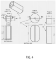
FIG. 4 shows exemplary dimensions of the device for occluding a patient's aorta ofFIG. 3 . -
FIG. 5 is a schematic view showing a method for inserting and locating the device of occluding a patient's aorta ofFIG. 3 inside of the patient's esophagus. -
FIG. 6 is a side, partial sectional view of a device for occluding a patient's aorta in accordance with certain aspects of an embodiment of the invention. -
FIG. 7 is a close-up, top, partial sectional view of a head assembly of the device ofFIG. 6 . -
FIG. 8 is close-up, bottom perspective, partial sectional view of the head assembly of the device ofFIG. 6 . -
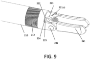
FIG. 9 is a close-up, side, partial sectional view of the head assembly of the device ofFIG. 6 . -
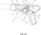
FIG. 10 is a close-up, side perspective sectional view of an actuator handle of the device ofFIG. 6 . -
FIG. 11 is a top perspective, partial sectional view of the device ofFIG. 6 showing three degrees of freedom of movement of the head assembly. -
FIG. 12 is a top perspective, partial sectional view of the device ofFIG. 6 . -
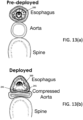
FIGs. 13(a) and 13(b) are cross-sectional views of a patient's esophagus, aorta and spine and showing deployment of a device in accordance with certain aspects of an embodiment. -
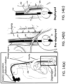
FIGs. 14(a), 14(b), and 14(c) are side views of a patient's esophagus, aorta and spine and showing deployment of a device in accordance with further aspects of an embodiment. - The following detailed description is provided to gain a comprehensive understanding of the methods, apparatuses and/or systems described herein. Various changes, modifications, and equivalents of the systems, apparatuses and/or methods described herein will suggest themselves to those of ordinary skill in the art.
- Descriptions of well-known functions and structures are omitted to enhance clarity and conciseness. The terminology used herein is for the purpose of describing particular embodiments only and is not intended to be limiting of the present disclosure. As used herein, the singular forms "a", "an" and "the" are intended to include the plural forms as well, unless the context clearly indicates otherwise. Furthermore, the use of the terms a, an, etc. does not denote a limitation of quantity, but rather denotes the presence of at least one of the referenced item.
- The use of the terms "first", "second", and the like does not imply any particular order, but they are included to identify individual elements. Moreover, the use of the terms first, second, etc. does not denote any order of importance, but rather the terms first, second, etc. are used to distinguish one element from another. It will be further understood that the terms "comprises" and/or "comprising", or "includes" and/or "including" when used in this specification, specify the presence of stated features, regions, integers, steps, operations, elements, and/or components, but do not preclude the presence or addition of one or more other features, regions, integers, steps, operations, elements, components, and/or groups thereof.
- Although some features may be described with respect to individual exemplary embodiments, aspects need not be limited thereto such that features from one or more exemplary embodiments may be combinable with other features from one or more exemplary embodiments.
- Provided herein are methods and devices that are configured to provide a short-term solution to major hemorrhagic bleeding to prevent extreme blood loss. For example, methods and devices in accordance with certain aspects of an embodiment can be used prior to admission to an emergency facility, while the patient is in the field, and prior to entering an operating room. Thus, the devices and methods disclosed herein are configured to:
- Reduce the aortic blood flow rate by up to approximately 90% through applying radial pressure to the aorta to substantially occlude the aorta. This will prevent blood from getting to the wound and, therefore, stop the hemorrhage.
- Impinge and/or occlude the aorta by inserting the device into the esophagus to compress the aorta from the patient's esophagus.
- The device according to certain aspects of an embodiment includes an esophageal tube and an actuator. At least a portion of the actuator may be positioned within a sleeve. Further, the device may include an anchor, such as at least one balloon (e.g., a gastric balloon) configured to secure placement of the actuator and/or esophageal tube within the patient.
- Considering the anatomy of the site of interest, and as shown in
FIG. 1 (reproduced from The McGraw-Hill Companies, Inc., copyright 2006), the esophagus and the aorta cross above the intersection with the diaphragm. At this site, the aorta is "sandwiched" between the spine and the esophagus. Thus, a device configured as described herein can be inserted into the esophagus through the mouth to this location, and used to apply posterior pressure against the aorta and toward the patient's spine, which pressure will impinge upon and/or occlude the aorta. - The pressure applied to the aorta can be directed towards the posterior side of the body, instead of applying pressure in all directions, to advantageously apply the force on the aorta itself and limit unnecessary stretching of the esophagus. Total aortic occlusion is common practice in many medical procedures that involves clamping the aorta. Clamping the aorta to occlude the aorta may require an external pressure of at least 10 times the internal pressure of the aorta. For example, if an internal aortic pressure is 10665.8 Pa (80 mmHg), an external pressure of 106658 Pa (800 mmHg) would need to be applied. The required force for this pressure is estimated to be about 6.8 Kgs (15 lbs). However, applying pressure slightly greater than 6.8 Kgs (15 lbs). would not be expected to cause any problems. The device according to certain aspects of an embodiment is preferably less than 4.5 cm in diameter so that it may be easily inserted through the mouth. This diameter is estimated based on other devices that can be inserted through the patient's mouth, however, other diameters that fit into a patient's mouth are feasible.
- As discussed in detail below, a device according to certain aspects of an embodiment includes at least one actuator to apply a force onto a patient's aorta. The actuator is configured to control the direction of the force that is applied to the patient's esophagus, and in turn their aorta. With reference to
FIGS. 3-5 , the actuator may in one embodiment include one or more magnets. For example, a first magnet may be a small internal magnet and a second magnet may be an external electromagnet. The actuators, such as the magnets, can be positioned to direct forces in a desired direction and with a desired intensity or amplitude (i.e., to control the force). As discussed in further detail below, the actuator may also comprise other mechanisms that apply an occluding force on the aorta, including pneumatic (e.g., symmetric or asymmetric balloons) or hydraulic forces, and mechanical mechanisms (e.g., caused by a pulley or lever arm, a scissor-like mechanism, rigid or semi-rigid catheter-like mechanisms, stent-like mechanisms, and the like). The magnitude of force can be controlled to further ensure efficiency of the device. There should generally be enough pressure to occlude the aorta, but the pressure should generally be controlled so that it does not damage internal structures such as the aorta, esophagus, and the spine. - One embodiment of the device is configured to be more easily inserted and placed at the site of interest than typical devices. For example, and with reference to
FIG. 2 , a device and method can be used similar to that of the Sengstaken-Blakemore tube. One such embodiment may include agastric balloon 10 that expands in the stomach to ensure thefirst balloon 12, or other portions of the device, are in the proper place and not in the stomach. Thus, a device in accordance with certain aspects of an embodiment may include a secondary (stomach or gastric)balloon 10 to ensure that the device is in the desired location and has not gone too far down the patient's esophagus and into the patient's stomach. A device in accordance with certain aspects of an embodiment may also include an esophageal tube for gastric content aspiration to remove the gastric contents from the patient's stomach to reduce the likelihood that the patient will vomit during use of the device. - A device formed in accordance with certain aspects of an embodiment is generally formed of simple materials. As shown in
FIG. 3 , thedevice 20 may, in accordance with certain aspects of an embodiment, include two magnets as described above, for example, afirst magnet 22 that is positioned in the device (e.g., positioned in the esophageal tube (e.g., from MedEx Supply)) that is relatively smaller and/or weaker than a second magnet. Exemplary magnets may be readily commercially obtained, by way of non-limiting example, from K&J Magnetics, Inc. A device according to certain features of an embodiment may further include asleeve 24 that can be manufactured according to typical methods, such as by additive manufacturing using CAD drawing designs. The sleeve is configured to be semi-rigid or flexible, such that it is formed of many typical materials, such as Ninjaflex material. - The device according to certain aspects of an embodiment can be assembled by placing the magnet in the sleeve and attaching the sleeve to an
esophageal tube 26. In some embodiments, thesleeve 24 can be modified to secure thefirst magnet 22. Thus, one embodiment of the device includes the first (internal)magnet 22, thesleeve 24, theesophageal tube 26, the second (external) magnet (not shown), and other assembly tools (e.g., sandpaper, scissors, and fasteners or adhesive such as glue). InFIG. 3 , an assembleddevice 20 is shown including anesophageal tube 26, amagnet 22 positioned within anencasement 24, and agastric balloon 10, andFIG. 4 provides exemplary dimensions for such device. - Testing of a device configured as above can include preliminary testing on an artificial model of the human aorta and esophagus. The artificial model can include a hard plastic spine, flexible plastic aorta, and flexible plastic esophagus. The artificial aorta can be filled with a fluid to mimic the pressure in the aorta. The device can be placed into the artificial esophagus, and the magnets positioned to test the ability of the magnets to occlude the aorta through the esophagus (i.e., induce an occluding force on the aorta by positioning the first and second magnet).
FIG. 5 illustrates one embodiment of a method for inserting and locating the device in a patient. - As discussed above, the esophageal tube can be purchased from typical medical device suppliers. In one embodiment of the device, at least one of the first or second magnets is an electromagnet. In another embodiment, the first or second magnet is a large (e.g., 4 in. x 4 in. x ½ in.) N52 magnet (e.g., as the second or external magnet). In one embodiment, the first (internal) magnet can be a smaller (3 in. x 1 in. x 1 in.) N52 magnet. In some embodiments, the magnets are encased in plastic to improve the safety of the device.
- Next, and in accordance with certain features of a particularly preferred embodiment of the invention, and with reference to
FIGs. 6 through 12 , adevice 200 for esophageal compression of a patient's aorta is provided including anesophageal tube 210, anactuator handle 220 at a proximal end ofesophageal tube 210, and ahead assembly 240 at a distal end ofesophageal tube 210, whichdevice 200 provides for improved control over the placement and direction of compressive forces on the interior of a patient's esophagus to compress the patient's aorta. More particularly,head assembly 240 ofdevice 200 is configured for three, distinct degrees of freedom of movement, as best viewed inFIGs. 6 and11 . Specifically,clamp blades 241 move in the direction of arrow A toward and away from one another, which allow for easier entry of the distal end ofdevice 200 into the patient's esophagus prior to separation ofclamp blades 241 to push against the interior wall of the patient's esophagus. Further, the pitch ofhead assembly 240 with respect toesophageal tube 210 may be modified by rotatinghead assembly 240 in the direction of arrow B (in plane B1 ofFIG. 11 ), and the yaw ofhead assembly 240 with respect toesophageal tube 210 may be modified by rotating head assembly in the direction of arrow C (in plane C1 ofFIG. 11 ), which additional movements provide for significantly improved control over the application of compressive force to the patient's esophagus and, in turn, the patient's aorta. - With particular reference to
FIGs. 7-9 ,head assembly 240 ofdevice 200 includesclamp blades 241 that are slidably and pivotably mounted at mountingarms 244 to apin 242, whichpin 242 is mounted atdistal end 211 ofesophageal tube 210. Optionally,esophageal tube 210, or portions thereof, may extend distallypast clamp blades 241, such that clamp blades 214 may extend through an opening inesophageal tube 210 when deployed to apply pressure to the patient's esophagus and aorta. Aspring 243 is positioned between mountingarms 244 ofclamp blades 241 and biases them away from one another and toward the interior walls ofesophageal tube 210 atdistal end 211. However,clamp blades 241 may also move toward one another to decrease a profile ofhead assembly 240 during insertion into a patient's esophagus. To effect such change in the distance betweenclamp blades 241, a clamp blade closing actuator 232 (FIG. 10 ) of actuator handle 220 is attached to clamp bladepitch control arms 244 through a clamp blade closurecontrol connector cable 224 that extends throughesophageal tube 210. As best viewed inFIGs. 7-9 , clampblade closure arms 223 are affixed at their distal ends to an outer face of clampblade mounting arms 244, and at their proximal ends to clamp blade closurecontrol connector cable 224, and are configured for scissor-like movement with respect to one another. Thus, as clamp blade closurecontrol connector cable 224 is pulled viaactuator 232 onactuator handle 220, clampblade closure arms 223 come together, in turn pushingclamp blades 241 toward one another to decrease the profile of the distal end ofdevice 200 as it is inserted into the patient's esophagus. Likewise, as clamp bladeclosure connector cable 224 is released,spring 243 biases clampblades 241 away from one another for applying compressive pressure against the interior wall of the patient's esophagus. - Further, as
clamp blades 241 are pivotably mounted to pin 242,clamp blades 241 may rotate aboutpin 242 to change the pitch ofclamp blades 241 with respect toesophageal tube 210. To effect such change in pitch ofclamp blades 241, a clamp blade pitch control actuator 231 (FIG. 10 ) of actuator handle 220 is attached to clamp bladepitch control arms 221 through a pitchcontrol connector cable 222 that extends throughesophageal tube 210. As shown inFIGs. 8 and9 ,pitch control arms 221 are affixed to clampblade mounting arms 244 at a location that is offset from a centerline of clampblade mounting arms 244. Thus, as clamp blade pitchcontrol connector cable 222 is pulled towardactuator handle 220,clamp blades 241 will pivot upward (from the perspective ofFIG. 9 ) aboutpin 242, and as clamp blade pitchcontrol connector cable 222 is pushed towardactuator handle 220,clamp blades 241 will pivot downward (from the perspective ofFIG. 9 ). Thus, a physician may readily modify the pitch orientation ofhead assembly 240 with respect toesophageal tube 210 to a desired, optimal position so as to best apply pressure to the patient's esophagus at the desired location. - Still further,
esophageal tube 210 preferably includes aflex section 212 that is positioned proximal todistal end 211 ofesophageal tube 210.Flex section 212 is preferably formed of the same material as esophageal tube 210 (which may be of like configuration to a standard endoscope, by way of non-limiting example), but with an accordion-like structure that increases the flexibility offlex section 212 significantly beyond the flexibility ofesophageal tube 210. Alternatively flexsection 212 may be formed of an alternative, more highly flexible bio-compatible material as may occur to those of ordinary skill in the art.Flex section 212 is positioned so as to allow pivoting ofhead assembly 240 with respect toesophageal tube 210 in the direction of arrow C (FIGs. 6 and11 ), thus modifying the yaw ofsuch head assembly 240 to even further control the application of force fromdevice 200 to the interior wall of the patient's esophagus and, in turn, to their aorta. To effect such change in yaw ofhead assembly 240, a clamp blade yaw control actuator 238 (FIG. 10 ) of actuator handle 220 is attached to theinterior wall 213 offlex section 212 through a yawcontrol connector cable 226 that extends throughesophageal tube 210. As shown inFIGs. 11 and12 ,yaw control arms 225 are affixed to theinterior wall 213 offlex section 212 so as to translate rotation ofyaw control actuator 238 onhandle 220 into pivoting offlex section 212. Thus, as clamp bladeyaw control actuator 238 is rotated in a first direction, yawcontrol connector cable 226 pullsyaw control arms 225 in a first direction to pivothead assembly 240 in that first direction, and as clamp bladeyaw control actuator 238 is rotated in a second, opposite direction, yawcontrol connector cable 226 pullsyaw control arms 225 in a second direction to pivothead assembly 240 in that second direction. Thus, a physician may likewise readily modify the yaw orientation ofhead assembly 240 with respect toesophageal tube 210 to a desired, optimal position so as to best apply pressure to the patient's esophagus at the desired location. -
FIG. 10 provides a close-up view of the actuator mechanism ofdevice 200 that allow a user to manipulatehead assembly 240 through three distinct degrees of freedom of movement. Clamp bladepitch control actuator 231 is moveably mounted inactuator handle 220, and is attached to clamp blade pitchcontrol connector cable 222. A head ofpitch control actuator 231 is providedratchet teeth 233 that releasably engage a pitch controlactuator ratchet arm 234 that is biased by aspring 238 to engagement withteeth 233. Thus, as clamp bladepitch control actuator 231 is moved with respect to handle 220, its position with respect to handle 220 is locked byratchet arm 234 to hold the position of pitch control actuator, and thus the pitch ofhead assembly 240, in place. Aratchet arm release 237 engages an end of pitch controlactuator ratchet arm 234, which when engaged liftsratchet arm 234 off of pitch control actuator ratchetteeth 233 to allow the physician to modify the pitch ofhead assembly 240. Similarly, clampblade closing actuator 232 is moveably mounted inactuator handle 220, and is attached to clamp blade closurecontrol connector cable 224. A head of closingactuator 232 is providedratchet teeth 235 that releasably engage a closingactuator ratchet arm 236 that is biased by aspring 238 to engagement withteeth 235. Thus, as clampblade closing actuator 232 is moved with respect to handle 220, its position with respect to handle 220 is locked byratchet arm 236 to hold the position of clampblade closing actuator 232, and thus the separation ofclamp blades 241, in place. Aratchet arm release 237 similarly engages an end of closingactuator ratchet arm 236, which when engaged liftsratchet arm 236 off of closing actuator ratchetteeth 235 to allow the physician to modify the separation betweenclamp blades 241. Finally, clamp bladeyaw control actuator 238 is moveably mounted inactuator handle 220, and is attached to clamp blade yawcontrol connector cable 226, such that movement of clamp bladeyaw control actuator 238 in either direction causes pivoting ofhead assembly 240 atflex section 212 ofesophageal tube 210. - Optionally, one or more balloons, such as
gastric balloon 10 ofFIG. 3 , may also be provided to even further control placement and direction of the application of compressive force against the interior of the patient's esophagus and, in turn, the patient's aorta. For example, a gastric balloon may be placed throughesophageal tube 210 and extend out ofdistal end 211 ofesophageal tube 210 andpast clamp blades 241 for placement in the patient's stomach, thus aiding in proper positioning ofhead assembly 240 adjacent the desired portion of the patient's esophagus. Alternatively or additionally, a balloon may be positionedadjacent head assembly 240 which, when inflated, will pushhead assembly 240 in the desired direction toward the patient's aorta, thus both further anchoring thedevice 200 at the desired location in the patient's esophagus, and further isolating the direction of force application to the patient's esophagus. -
FIG. 13(a) provides a cross-sectional view of patient's esophagus, aorta, and spine, withdevice 200 positioned in the patient's esophagus at a location such that its deployment will cause impingement of the patient's aorta between their esophagus and spine, as shown inFIG. 13(b) . As shown inFIGS. 13(a) and (b) , in certain configurations,clamp blades 241 need not be parallel to one another. Rather, clampblades 241 may be angularly offset from one another, such that as they pivot aboutpin 242, the distal ends ofclamp blades 241 extend outward and away from one another, in turn expanding the width of esophageal tissue contacted byclamp blades 241, and in turn increasing the surface area of the patient's esophagus that applies an impinging force to the patient's aorta. - Further,
FIGs. 14(a) - 14(c) show views of adevice 200 placed in a patient's esophagus, in which head assembly 240 ofdevice 200 may include aplate 245 affixed to the distal ends ofclamp blades 241. In certain configurations,plate 245 may form a portion of the outer wall ofesophageal tube 210. In this configuration, asclamp blades 241 are rotated aboutpin 242, they liftplate 245 and pushplate 245 against the interior wall of the patient's esophagus, such thatplate 245 then compresses the patient's aorta by pushing against the esophageal wall. Optionally,separate plates 245 may be provided, with onesuch plate 245 attached to the distal end of eachclamp blade 241. Such one ormore plates 245 may be provided to increase the linear span of esophageal tissue contacted bydevice 200, and again in turn increase the surface area of the patient's esophagus that applies an impinging force to the patient's aorta. - Abdominal hemorrhage control presents a major unmet clinical need. By controlling the aortic flow in the descending portion of the aorta, methods and devices according to at least certain aspects of an embodiment substantially prevent blood flow to the lower chest and abdomen. This will significantly reduce blood loss and extend the life of the patient long enough to allow for a surgeon to access and repair the wound area. Methods and devices in accordance with certain aspects of an embodiment are configured to be less invasive and easier to implement for purposes of aortic occlusion than typical methods, such as REBOA.
- Devices configured in accordance with at least certain aspects of the invention are further configured to be used in hospitals, emergency rooms, field operations, and trauma centers by many medical professionals, such as more than can use typical aortic occlusion methods.
-
- 1. Arsenal Medical. "Foam System for Acute Hemorrhage." Arsenal Medical. 2017. http://www.arsenalmedical.com/foam-system-acute-hemorrhage.
- 2. Babin-Ebell, J., Gimpel-Henning, K., Sievers, H. H., & Scharfschwerdt, M. (2010). Influence of clamp duration and pressure on endothelial damage in aortic cross-clamping. Interactive cardiovascular and thoracic surgery, 10(2), 168-171.
- 3.
Blikken, Wayland G. "Esophageal/Stethoscopic Gastric Tube." U.S. Patent and Trademark Office. Patent No. 5191892. March 9, 1993 . - 4. Compression Works. "Abdominal Aortic Junctional Tourniquet." Compression Works. http://compressionworks.com/products-aajt/.
- 5. Morrison, Jonathan J., and Todd E. Rasmussen. "Noncompressible torso hemorrhage: a review with contemporary definitions and management strategies." Surgical Clinics of North America 92.4 (2012): 843-858.
- 6. Riley, M. A., Walmsley, A. D., Speight, J. D., & Harris, I. R. (2002). Magnets in medicine. Materials science and technology, 18(1), 1-12.
- 7. Trauma Ready. "REBOA: Resuscitative Endovascular Balloon Occlusion of the Aorta." Trauma Ready. http://www.traumaready.com/reboa/#.WjF8AEqnFPZ
Claims (7)
- A device (200) for the esophageal compression of a patient's aorta, comprising:an elongate tube (210);an actuator handle (220) at a proximal end of said elongate tube (210); anda head assembly (240) at a distal end of said elongate tube (210), said head assembly (240) further comprising a pair of clamp blades (241) that are mounted to said elongate tube for slidable movement along a first axis that is perpendicular to a second, longitudinal axis of said elongate tube (210), and that are mounted to said elongate tube (210) for pivotable movement about said first axis;wherein said actuator handle (220) engages said head assembly (240) to cause said head assembly to move through at least one of three distinct degrees of freedom of movement to apply pressure to a patient's tissue.
- The device (200) of claim 1, wherein said pair of clamp blades (241) are spring biased away from one another.
- The device (200) of claim 2, further comprising:a clamp blade pitch control actuator (231) moveably mounted to said handle (220) and engaging said pair of clamp blades (241) to pivot said clamp blades about said first axis; anda clamp blade closing actuator (232) moveably mounted to said handle (220) and engaging said pair of clamp blades (241) to slide said clamp blades along said first axis.
- The device (200) of claim 1, wherein said head assembly (240) is further pivotable about a third axis that is perpendicular to said first and second axes.
- The device (200) of claim 4, further comprising a clamp blade yaw control actuator (238) movably mounted to said handle (220) and engaging said head assembly (240) to pivot said head assembly (240) about said third axis.
- The device (200) of claim 5, said elongate tube (210) further comprising a flex section (212) of higher flexibility than a remainder of said elongate tube (210), wherein said flex section (212) is positioned proximally from the distal end of said elongate tube.
- The device (200) of claim 6, wherein said clamp blade yaw control actuator (238) engages said flex section (212) to pivot said head assembly (240) at said flex section (212).
Applications Claiming Priority (2)
| Application Number | Priority Date | Filing Date | Title |
|---|---|---|---|
| US201862638600P | 2018-03-05 | 2018-03-05 | |
| PCT/US2019/020693 WO2019173294A1 (en) | 2018-03-05 | 2019-03-05 | Trans-esophageal aortic flow rate control |
Publications (3)
| Publication Number | Publication Date |
|---|---|
| EP3761888A1 EP3761888A1 (en) | 2021-01-13 |
| EP3761888A4 EP3761888A4 (en) | 2022-03-09 |
| EP3761888B1 true EP3761888B1 (en) | 2025-03-05 |
Family
ID=67846317
Family Applications (1)
| Application Number | Title | Priority Date | Filing Date |
|---|---|---|---|
| EP19764860.3A Active EP3761888B1 (en) | 2018-03-05 | 2019-03-05 | Trans-esophageal aortic flow rate control |
Country Status (4)
| Country | Link |
|---|---|
| US (2) | US11523832B2 (en) |
| EP (1) | EP3761888B1 (en) |
| ES (1) | ES3015555T3 (en) |
| WO (1) | WO2019173294A1 (en) |
Families Citing this family (3)
| Publication number | Priority date | Publication date | Assignee | Title |
|---|---|---|---|---|
| CA3143324A1 (en) * | 2019-06-14 | 2020-12-17 | Lcmedical Llc | Intracardiac delivery catheter and method of use |
| US20220054311A1 (en) * | 2020-08-12 | 2022-02-24 | United States Government As Represented By The Department Of Veterans Affairs | Eye Drop Dispensing Apparatus |
| WO2025032148A1 (en) * | 2023-08-07 | 2025-02-13 | Neurescue Aps | A device for providing resuscitation or suspended state in cardiac arrest |
Family Cites Families (14)
| Publication number | Priority date | Publication date | Assignee | Title |
|---|---|---|---|---|
| US5191892A (en) | 1991-09-10 | 1993-03-09 | Blikken Wayland G | Esophageal/stethoscopic gastric tube |
| US5235966A (en) | 1991-10-17 | 1993-08-17 | Jay Jamner | Endoscopic retractor |
| US5626618A (en) | 1993-09-24 | 1997-05-06 | The Ohio State University | Mechanical adjunct to cardiopulmonary resuscitation (CPR), and an electrical adjunct to defibrillation countershock, cardiac pacing, and cardiac monitoring |
| CA2144211C (en) | 1994-03-16 | 2005-05-24 | David T. Green | Surgical instruments useful for endoscopic spinal procedures |
| US5474533A (en) | 1994-04-11 | 1995-12-12 | The Ohio State University | Intrathoracic mechanical, electrical and temperature adjunct to cardiopulmonary cerebral resuscitation, shock, head injury, hypothermia and hyperthermia |
| US5716386A (en) * | 1994-06-27 | 1998-02-10 | The Ohio State University | Non-invasive aortic impingement and core and cerebral temperature manipulation |
| WO1999000057A1 (en) | 1997-06-27 | 1999-01-07 | Michigan Instruments, Inc. | Non-invasive aortic impingement |
| US7775972B2 (en) * | 1998-02-24 | 2010-08-17 | Hansen Medical, Inc. | Flexible instrument |
| US6770081B1 (en) | 2000-01-07 | 2004-08-03 | Intuitive Surgical, Inc. | In vivo accessories for minimally invasive robotic surgery and methods |
| US20130197555A1 (en) * | 2002-07-01 | 2013-08-01 | Recor Medical, Inc. | Intraluminal devices and methods for denervation |
| US7615067B2 (en) * | 2006-06-05 | 2009-11-10 | Cambridge Endoscopic Devices, Inc. | Surgical instrument |
| US20110144450A1 (en) | 2009-10-19 | 2011-06-16 | Anthony Paolitto | Tissue retractor with movable blades and articulating wrist joint |
| US9707076B2 (en) | 2012-08-23 | 2017-07-18 | Minimally Invasive Surgical Access Limited | Direct aortic access system for transcatheter aortic valve procedures |
| CA3014502A1 (en) * | 2016-02-22 | 2017-08-31 | Uti Limited Partnership | An apparatus, system and method for treating hemorrhage |
-
2019
- 2019-03-05 US US16/978,280 patent/US11523832B2/en active Active
- 2019-03-05 WO PCT/US2019/020693 patent/WO2019173294A1/en not_active Ceased
- 2019-03-05 ES ES19764860T patent/ES3015555T3/en active Active
- 2019-03-05 EP EP19764860.3A patent/EP3761888B1/en active Active
-
2022
- 2022-12-13 US US18/064,989 patent/US12402888B2/en active Active
Also Published As
| Publication number | Publication date |
|---|---|
| US20230225741A1 (en) | 2023-07-20 |
| ES3015555T3 (en) | 2025-05-06 |
| US11523832B2 (en) | 2022-12-13 |
| US20210000479A1 (en) | 2021-01-07 |
| EP3761888A4 (en) | 2022-03-09 |
| US12402888B2 (en) | 2025-09-02 |
| EP3761888A1 (en) | 2021-01-13 |
| WO2019173294A1 (en) | 2019-09-12 |
Similar Documents
| Publication | Publication Date | Title |
|---|---|---|
| US12402888B2 (en) | Trans-esophageal aortic flow rate control | |
| US11911044B2 (en) | Resection line guide for a medical procedure and method of using same | |
| JP6549770B2 (en) | Surgical clips, cartridges and kits | |
| US7235090B2 (en) | Method and apparatus for solid organ tissue approximation | |
| EP1447052B1 (en) | GERD treatment apparatus | |
| US6387114B2 (en) | Gastrointestinal compression clips | |
| EP2308383B1 (en) | Internal retractor systems | |
| JP6130302B2 (en) | System for sealing tissue wall stings | |
| EP2994060A2 (en) | Tissue ligation devices and methods therefor | |
| EP2182853A2 (en) | Suspension/retraction device for surgical manipulation | |
| JP2021533849A (en) | Devices and methods for compressing tumors | |
| US20220054138A1 (en) | Trans-esophageal aortic flow rate control | |
| CN121889111A (en) | Biological construct delivery system | |
| HK1112827B (en) | Gerd treatment apparatus | |
| AU2007231915A1 (en) | GERD treatment apparatus and method |
Legal Events
| Date | Code | Title | Description |
|---|---|---|---|
| STAA | Information on the status of an ep patent application or granted ep patent |
Free format text: STATUS: THE INTERNATIONAL PUBLICATION HAS BEEN MADE |
|
| PUAI | Public reference made under article 153(3) epc to a published international application that has entered the european phase |
Free format text: ORIGINAL CODE: 0009012 |
|
| STAA | Information on the status of an ep patent application or granted ep patent |
Free format text: STATUS: REQUEST FOR EXAMINATION WAS MADE |
|
| 17P | Request for examination filed |
Effective date: 20200903 |
|
| AK | Designated contracting states |
Kind code of ref document: A1 Designated state(s): AL AT BE BG CH CY CZ DE DK EE ES FI FR GB GR HR HU IE IS IT LI LT LU LV MC MK MT NL NO PL PT RO RS SE SI SK SM TR |
|
| AX | Request for extension of the european patent |
Extension state: BA ME |
|
| DAV | Request for validation of the european patent (deleted) | ||
| DAX | Request for extension of the european patent (deleted) | ||
| A4 | Supplementary search report drawn up and despatched |
Effective date: 20220209 |
|
| RIC1 | Information provided on ipc code assigned before grant |
Ipc: A61B 17/29 20060101ALI20220203BHEP Ipc: A61B 17/22 20060101ALI20220203BHEP Ipc: A61B 17/12 20060101AFI20220203BHEP |
|
| GRAP | Despatch of communication of intention to grant a patent |
Free format text: ORIGINAL CODE: EPIDOSNIGR1 |
|
| STAA | Information on the status of an ep patent application or granted ep patent |
Free format text: STATUS: GRANT OF PATENT IS INTENDED |
|
| INTG | Intention to grant announced |
Effective date: 20241002 |
|
| GRAS | Grant fee paid |
Free format text: ORIGINAL CODE: EPIDOSNIGR3 |
|
| GRAA | (expected) grant |
Free format text: ORIGINAL CODE: 0009210 |
|
| STAA | Information on the status of an ep patent application or granted ep patent |
Free format text: STATUS: THE PATENT HAS BEEN GRANTED |
|
| AK | Designated contracting states |
Kind code of ref document: B1 Designated state(s): AL AT BE BG CH CY CZ DE DK EE ES FI FR GB GR HR HU IE IS IT LI LT LU LV MC MK MT NL NO PL PT RO RS SE SI SK SM TR |
|
| REG | Reference to a national code |
Ref country code: GB Ref legal event code: FG4D |
|
| REG | Reference to a national code |
Ref country code: CH Ref legal event code: EP |
|
| REG | Reference to a national code |
Ref country code: DE Ref legal event code: R096 Ref document number: 602019066896 Country of ref document: DE |
|
| REG | Reference to a national code |
Ref country code: IE Ref legal event code: FG4D |
|
| REG | Reference to a national code |
Ref country code: ES Ref legal event code: FG2A Ref document number: 3015555 Country of ref document: ES Kind code of ref document: T3 Effective date: 20250506 |
|
| P01 | Opt-out of the competence of the unified patent court (upc) registered |
Free format text: CASE NUMBER: APP_20709/2025 Effective date: 20250430 |
|
| PG25 | Lapsed in a contracting state [announced via postgrant information from national office to epo] |
Ref country code: RS Free format text: LAPSE BECAUSE OF FAILURE TO SUBMIT A TRANSLATION OF THE DESCRIPTION OR TO PAY THE FEE WITHIN THE PRESCRIBED TIME-LIMIT Effective date: 20250605 |
|
| PG25 | Lapsed in a contracting state [announced via postgrant information from national office to epo] |
Ref country code: FI Free format text: LAPSE BECAUSE OF FAILURE TO SUBMIT A TRANSLATION OF THE DESCRIPTION OR TO PAY THE FEE WITHIN THE PRESCRIBED TIME-LIMIT Effective date: 20250305 |
|
| REG | Reference to a national code |
Ref country code: NL Ref legal event code: MP Effective date: 20250305 |
|
| PGFP | Annual fee paid to national office [announced via postgrant information from national office to epo] |
Ref country code: ES Payment date: 20250401 Year of fee payment: 7 |
|
| REG | Reference to a national code |
Ref country code: LT Ref legal event code: MG9D |
|
| PG25 | Lapsed in a contracting state [announced via postgrant information from national office to epo] |
Ref country code: NO Free format text: LAPSE BECAUSE OF FAILURE TO SUBMIT A TRANSLATION OF THE DESCRIPTION OR TO PAY THE FEE WITHIN THE PRESCRIBED TIME-LIMIT Effective date: 20250605 |
|
| PG25 | Lapsed in a contracting state [announced via postgrant information from national office to epo] |
Ref country code: HR Free format text: LAPSE BECAUSE OF FAILURE TO SUBMIT A TRANSLATION OF THE DESCRIPTION OR TO PAY THE FEE WITHIN THE PRESCRIBED TIME-LIMIT Effective date: 20250305 |
|
| PG25 | Lapsed in a contracting state [announced via postgrant information from national office to epo] |
Ref country code: LV Free format text: LAPSE BECAUSE OF FAILURE TO SUBMIT A TRANSLATION OF THE DESCRIPTION OR TO PAY THE FEE WITHIN THE PRESCRIBED TIME-LIMIT Effective date: 20250305 |
|
| PG25 | Lapsed in a contracting state [announced via postgrant information from national office to epo] |
Ref country code: GR Free format text: LAPSE BECAUSE OF FAILURE TO SUBMIT A TRANSLATION OF THE DESCRIPTION OR TO PAY THE FEE WITHIN THE PRESCRIBED TIME-LIMIT Effective date: 20250606 Ref country code: BG Free format text: LAPSE BECAUSE OF FAILURE TO SUBMIT A TRANSLATION OF THE DESCRIPTION OR TO PAY THE FEE WITHIN THE PRESCRIBED TIME-LIMIT Effective date: 20250305 |
|
| REG | Reference to a national code |
Ref country code: AT Ref legal event code: MK05 Ref document number: 1772170 Country of ref document: AT Kind code of ref document: T Effective date: 20250305 |
|
| PG25 | Lapsed in a contracting state [announced via postgrant information from national office to epo] |
Ref country code: NL Free format text: LAPSE BECAUSE OF FAILURE TO SUBMIT A TRANSLATION OF THE DESCRIPTION OR TO PAY THE FEE WITHIN THE PRESCRIBED TIME-LIMIT Effective date: 20250305 |
|
| PG25 | Lapsed in a contracting state [announced via postgrant information from national office to epo] |
Ref country code: SE Free format text: LAPSE BECAUSE OF FAILURE TO SUBMIT A TRANSLATION OF THE DESCRIPTION OR TO PAY THE FEE WITHIN THE PRESCRIBED TIME-LIMIT Effective date: 20250305 |
|
| PG25 | Lapsed in a contracting state [announced via postgrant information from national office to epo] |
Ref country code: SM Free format text: LAPSE BECAUSE OF FAILURE TO SUBMIT A TRANSLATION OF THE DESCRIPTION OR TO PAY THE FEE WITHIN THE PRESCRIBED TIME-LIMIT Effective date: 20250305 |
|
| PG25 | Lapsed in a contracting state [announced via postgrant information from national office to epo] |
Ref country code: PT Free format text: LAPSE BECAUSE OF FAILURE TO SUBMIT A TRANSLATION OF THE DESCRIPTION OR TO PAY THE FEE WITHIN THE PRESCRIBED TIME-LIMIT Effective date: 20250707 |
|
| PG25 | Lapsed in a contracting state [announced via postgrant information from national office to epo] |
Ref country code: PL Free format text: LAPSE BECAUSE OF FAILURE TO SUBMIT A TRANSLATION OF THE DESCRIPTION OR TO PAY THE FEE WITHIN THE PRESCRIBED TIME-LIMIT Effective date: 20250305 |
|
| PG25 | Lapsed in a contracting state [announced via postgrant information from national office to epo] |
Ref country code: AT Free format text: LAPSE BECAUSE OF FAILURE TO SUBMIT A TRANSLATION OF THE DESCRIPTION OR TO PAY THE FEE WITHIN THE PRESCRIBED TIME-LIMIT Effective date: 20250305 |
|
| PG25 | Lapsed in a contracting state [announced via postgrant information from national office to epo] |
Ref country code: CZ Free format text: LAPSE BECAUSE OF FAILURE TO SUBMIT A TRANSLATION OF THE DESCRIPTION OR TO PAY THE FEE WITHIN THE PRESCRIBED TIME-LIMIT Effective date: 20250305 Ref country code: EE Free format text: LAPSE BECAUSE OF FAILURE TO SUBMIT A TRANSLATION OF THE DESCRIPTION OR TO PAY THE FEE WITHIN THE PRESCRIBED TIME-LIMIT Effective date: 20250305 |
|
| REG | Reference to a national code |
Ref country code: CH Ref legal event code: H13 Free format text: ST27 STATUS EVENT CODE: U-0-0-H10-H13 (AS PROVIDED BY THE NATIONAL OFFICE) Effective date: 20251023 |
|
| PG25 | Lapsed in a contracting state [announced via postgrant information from national office to epo] |
Ref country code: RO Free format text: LAPSE BECAUSE OF FAILURE TO SUBMIT A TRANSLATION OF THE DESCRIPTION OR TO PAY THE FEE WITHIN THE PRESCRIBED TIME-LIMIT Effective date: 20250305 |
|
| PG25 | Lapsed in a contracting state [announced via postgrant information from national office to epo] |
Ref country code: SK Free format text: LAPSE BECAUSE OF FAILURE TO SUBMIT A TRANSLATION OF THE DESCRIPTION OR TO PAY THE FEE WITHIN THE PRESCRIBED TIME-LIMIT Effective date: 20250305 |
|
| PG25 | Lapsed in a contracting state [announced via postgrant information from national office to epo] |
Ref country code: IS Free format text: LAPSE BECAUSE OF FAILURE TO SUBMIT A TRANSLATION OF THE DESCRIPTION OR TO PAY THE FEE WITHIN THE PRESCRIBED TIME-LIMIT Effective date: 20250705 |
|
| PG25 | Lapsed in a contracting state [announced via postgrant information from national office to epo] |
Ref country code: LU Free format text: LAPSE BECAUSE OF NON-PAYMENT OF DUE FEES Effective date: 20250305 |
|
| REG | Reference to a national code |
Ref country code: DE Ref legal event code: R097 Ref document number: 602019066896 Country of ref document: DE |
|
| REG | Reference to a national code |
Ref country code: BE Ref legal event code: MM Effective date: 20250331 |
|
| PG25 | Lapsed in a contracting state [announced via postgrant information from national office to epo] |
Ref country code: MC Free format text: LAPSE BECAUSE OF FAILURE TO SUBMIT A TRANSLATION OF THE DESCRIPTION OR TO PAY THE FEE WITHIN THE PRESCRIBED TIME-LIMIT Effective date: 20250305 |
|
| PLBE | No opposition filed within time limit |
Free format text: ORIGINAL CODE: 0009261 |
|
| STAA | Information on the status of an ep patent application or granted ep patent |
Free format text: STATUS: NO OPPOSITION FILED WITHIN TIME LIMIT |
|
| PG25 | Lapsed in a contracting state [announced via postgrant information from national office to epo] |
Ref country code: DK Free format text: LAPSE BECAUSE OF FAILURE TO SUBMIT A TRANSLATION OF THE DESCRIPTION OR TO PAY THE FEE WITHIN THE PRESCRIBED TIME-LIMIT Effective date: 20250305 |
|
| REG | Reference to a national code |
Ref country code: CH Ref legal event code: L10 Free format text: ST27 STATUS EVENT CODE: U-0-0-L10-L00 (AS PROVIDED BY THE NATIONAL OFFICE) Effective date: 20260114 |
|
| PG25 | Lapsed in a contracting state [announced via postgrant information from national office to epo] |
Ref country code: BE Free format text: LAPSE BECAUSE OF NON-PAYMENT OF DUE FEES Effective date: 20250331 |
|
| PG25 | Lapsed in a contracting state [announced via postgrant information from national office to epo] |
Ref country code: CH Free format text: LAPSE BECAUSE OF NON-PAYMENT OF DUE FEES Effective date: 20250331 |
|
| PG25 | Lapsed in a contracting state [announced via postgrant information from national office to epo] |
Ref country code: IE Free format text: LAPSE BECAUSE OF NON-PAYMENT OF DUE FEES Effective date: 20250305 |
|
| 26N | No opposition filed |
Effective date: 20251208 |
|
| PGFP | Annual fee paid to national office [announced via postgrant information from national office to epo] |
Ref country code: GB Payment date: 20260327 Year of fee payment: 8 |
|
| PGFP | Annual fee paid to national office [announced via postgrant information from national office to epo] |
Ref country code: DE Payment date: 20260327 Year of fee payment: 8 |
|
| PGFP | Annual fee paid to national office [announced via postgrant information from national office to epo] |
Ref country code: IT Payment date: 20260319 Year of fee payment: 8 |
|
| PGFP | Annual fee paid to national office [announced via postgrant information from national office to epo] |
Ref country code: FR Payment date: 20260325 Year of fee payment: 8 |