EP3761757A1 - Heating device and method for detecting failure of heating device - Google Patents
Heating device and method for detecting failure of heating device Download PDFInfo
- Publication number
- EP3761757A1 EP3761757A1 EP19760536.3A EP19760536A EP3761757A1 EP 3761757 A1 EP3761757 A1 EP 3761757A1 EP 19760536 A EP19760536 A EP 19760536A EP 3761757 A1 EP3761757 A1 EP 3761757A1
- Authority
- EP
- European Patent Office
- Prior art keywords
- heater
- change rate
- item
- heat
- heated
- Prior art date
- Legal status (The legal status is an assumption and is not a legal conclusion. Google has not performed a legal analysis and makes no representation as to the accuracy of the status listed.)
- Granted
Links
Images


Classifications
-
- H—ELECTRICITY
- H05—ELECTRIC TECHNIQUES NOT OTHERWISE PROVIDED FOR
- H05B—ELECTRIC HEATING; ELECTRIC LIGHT SOURCES NOT OTHERWISE PROVIDED FOR; CIRCUIT ARRANGEMENTS FOR ELECTRIC LIGHT SOURCES, IN GENERAL
- H05B1/00—Details of electric heating devices
- H05B1/02—Automatic switching arrangements specially adapted to apparatus ; Control of heating devices
- H05B1/0227—Applications
- H05B1/023—Industrial applications
-
- G—PHYSICS
- G05—CONTROLLING; REGULATING
- G05D—SYSTEMS FOR CONTROLLING OR REGULATING NON-ELECTRIC VARIABLES
- G05D23/00—Control of temperature
-
- G—PHYSICS
- G05—CONTROLLING; REGULATING
- G05D—SYSTEMS FOR CONTROLLING OR REGULATING NON-ELECTRIC VARIABLES
- G05D23/00—Control of temperature
- G05D23/19—Control of temperature characterised by the use of electric means
- G05D23/1902—Control of temperature characterised by the use of electric means characterised by the use of a variable reference value
-
- G—PHYSICS
- G05—CONTROLLING; REGULATING
- G05B—CONTROL OR REGULATING SYSTEMS IN GENERAL; FUNCTIONAL ELEMENTS OF SUCH SYSTEMS; MONITORING OR TESTING ARRANGEMENTS FOR SUCH SYSTEMS OR ELEMENTS
- G05B6/00—Internal feedback arrangements for obtaining particular characteristics, e.g. proportional, integral or differential
- G05B6/02—Internal feedback arrangements for obtaining particular characteristics, e.g. proportional, integral or differential electric
-
- H—ELECTRICITY
- H05—ELECTRIC TECHNIQUES NOT OTHERWISE PROVIDED FOR
- H05B—ELECTRIC HEATING; ELECTRIC LIGHT SOURCES NOT OTHERWISE PROVIDED FOR; CIRCUIT ARRANGEMENTS FOR ELECTRIC LIGHT SOURCES, IN GENERAL
- H05B2203/00—Aspects relating to Ohmic resistive heating covered by group H05B3/00
- H05B2203/035—Electrical circuits used in resistive heating apparatus
Definitions
- the present invention relates to a heating device that includes a heater configured to heat an item to be heated, a temperature detection unit configured to detect a temperature of the item to be heated, and a temperature adjustment unit configured to control the heater. Also, the invention relates to a method for detecting a failure in a heating device.
- Patent Literature 1 discloses a method of determining a state of a control target with reference to a behavior in a control transient state, a representative example of which is a step response.
- Patent Literature 1 Japanese Patent No. 4481953
- Patent Literature 1 According to a method for determining a state of a control target on the basis of a behavior of a feedback system when a transient state is caused to occur as disclosed in Patent Literature 1, it is not possible to detect how much the respective changes related to heat-retaining properties of an item to be heated have occurred.
- an objective of the invention is to provide a heating device and a failure detecting method of a heating device capable of detecting a change related to heat-retaining properties of an item to be heated.
- a heating device that includes a heater configured to heat an item to be heated, a temperature detection unit configured to detect a temperature of the item to be heated, and a temperature adjustment unit configured to control the heater on the basis of a detected value of the temperature detection unit and a target temperature so that the temperature of the item to be heated reaches the target temperature
- the heating device including; a system gain change rate calculation unit configured to obtain a temperature increase value of the item to be heated from the detected value of the temperature detection unit, obtain a system gain, which is a ratio of the temperature increase value of the item to be heated with respect to electric power inputted to the heater, and obtain, as a system gain change rate, a rate of change from an initial value of the system gain; and a heat-retaining property change rate calculation unit configured to obtain a rate of change in heat-retaining properties of the item to be heated from the system gain change rate.
- the heating device further includes: a heater resistance value change rate calculation unit configured to obtain a resistance value of the heater from a voltage and a current applied to the heater and obtain, as a heater resistance value change rate, a rate of change from an initial value of the resistance value, and the heat-retaining property change rate calculation unit obtains the rate of change in heat-retaining properties of the item to be heated from the system gain change rate and the heater resistance value change rate.
- a heater resistance value change rate calculation unit configured to obtain a resistance value of the heater from a voltage and a current applied to the heater and obtain, as a heater resistance value change rate, a rate of change from an initial value of the resistance value
- the heat-retaining property change rate calculation unit obtains the rate of change in heat-retaining properties of the item to be heated from the system gain change rate and the heater resistance value change rate.
- the heating device further includes: a heater voltage change rate calculation unit configured to obtain, as a heater voltage change rate, a rate of change from an initial value of a voltage applied to the heater, and the heat-retaining property change rate calculation unit obtains the rate of change in heat-retaining properties of the item to be heated from the system gain change rate and the heater voltage change rate.
- a heater voltage change rate calculation unit configured to obtain, as a heater voltage change rate, a rate of change from an initial value of a voltage applied to the heater
- the heat-retaining property change rate calculation unit obtains the rate of change in heat-retaining properties of the item to be heated from the system gain change rate and the heater voltage change rate.
- the heating device further includes: a heater voltage change rate calculation unit configured to obtain, as a heater voltage change rate, a rate of change from an initial value of a voltage applied to the heater, and the heat-retaining property change rate calculation unit obtains the rate of change in heat-retaining properties of the item to be heated from the system gain change rate, the heater resistance value change rate, and the heater voltage change rate.
- a heater voltage change rate calculation unit configured to obtain, as a heater voltage change rate, a rate of change from an initial value of a voltage applied to the heater
- the heat-retaining property change rate calculation unit obtains the rate of change in heat-retaining properties of the item to be heated from the system gain change rate, the heater resistance value change rate, and the heater voltage change rate.
- the heating device further includes: a heat-retaining property failure detection unit configured to detect a failure in the heat-retaining properties by comparing the heat-retaining property change rate with a threshold for the heat-retaining property change rate.
- the heating device further includes: a heater resistance value failure detection unit configured to detect a failure in the resistance value of the heater by comparing the heater resistance value change rate with a threshold value for the heater resistance value change rate.
- the heating device further includes: a heater voltage failure detection unit configured to detect a failure in the voltage applied to the heater by comparing the heater voltage change rate with a threshold value for the heater voltage change rate.
- a failure detecting method of a heating device that includes a heater configured to heat an item to be heated, a temperature detection unit configured to detect a temperature of the item to be heated, and a temperature adjustment unit configured to control the heater on the basis of a detected value of the temperature detection unit and a target temperature so that the temperature of the item to be heated reaches the target temperature
- the failure detecting method including: obtaining a temperature increase value of the item to be heated from the detected value of the temperature detection unit, obtaining a system gain, which is a ratio of the temperature increase value of the item to be heated with respect to electric power inputted to the heater, and obtaining, as a system gain change rate, a rate of change from an initial value of the system gain; and obtaining a rate of change in heat-retaining properties of the item to be heated from the system gain change rate and detecting a failure in the heating device depending on whether or not the rate of change in heat-retaining properties exceeds a threshold value.
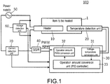
- FIG. 1 is a diagram illustrating a configuration of a heating device 100 according to an embodiment of the invention.
- the heating device 100 includes a heater 10 configured to heat an item to be heated 1, a temperature detection unit 20 configured to detect a temperature of the item to be heated 1, and a temperature adjustment unit 30 configured to control the heater 10 such that the temperature of the item to be heated 1 reaches a target temperature on the basis of a detected value of the temperature detection unit 20 and the target temperature.
- the temperature adjustment unit 30 includes a system gain change rate calculation unit, a heater resistance value change rate calculation unit, a heater voltage change rate calculation unit, and a heat-retaining property change rate calculation unit.
- the system gain change rate calculation unit obtains a temperature increase value of the item to be heated 1 from the detected value of the temperature detection unit 20, obtains a system gain, which is a ratio of the temperature increase value of the item to be heated 1 with respect to electric power inputted to the heater 10, and obtains a rate of change from an initial value of the system gain.
- the heater resistance value change rate calculation unit obtains a resistance value of the heater 10 from a voltage and a current applied to the heater 10 and obtains a rate of change from an initial value of the resistance value.
- the heater voltage change rate calculation unit obtains a rate of change in voltage applied to the heater 10 from an initial value thereof. Also, the heat-retaining property change rate calculation unit obtains a rate of change in heat-retaining properties of the item to be heated from the system gain change rate, the heater resistance value change rate, and the heater voltage change rate.
- FIG. 1 is a diagram illustrating a configuration of the heating device 100 according to the embodiment of the invention.
- the heating device 100 includes the heater 10 configured to heat the item to be heated 1, the temperature detection unit 20 configured to detect the temperature of the item to be heated 1, the temperature adjustment unit 30 configured to control the heater 10 on the basis of the detected value of the temperature detection unit 20 and the target temperature, a solid state switch 40, a heater power supply 50, a voltage detection unit 60 configured to detect a voltage applied to the heater, and a current detection unit 70 configured to detect a current flowing through the heater 10.
- the item to be heated 1 is a molded article of metal or the like. Since FIG. 1 is a block configuration diagram and the item to be heated 1 is conceptually illustrated, an actual shape thereof is appropriately defined.
- the item to be heated 1 is a heating unit of a packaging machine configured to heat a resin and package an article, for example.
- the heater 10 and the temperature detection unit 20 are provided in the heating unit.
- the temperature adjustment unit 30 includes a voltage-temperature conversion unit 31 configured to convert a voltage output from the temperature detection unit 20 into a temperature information signal, an operation amount-PWM conversion unit 32 configured to perform PWM control on the solid state switch 40, and an operation amount conversion unit 33.
- the operation amount conversion unit 33 is a PID controller and obtains the amount of operation through PID control on the basis of temperature information and target temperature information obtained by the voltage-temperature conversion unit 31.
- the operation amount conversion unit 33 performs an arithmetic operation as the system gain change rate calculation unit, an arithmetic operation as the heater resistance value change rate calculation unit, an arithmetic operation as the heater voltage change rate calculation unit, and an arithmetic operation as the heat-retaining property change rate calculation unit. These arithmetic operations will be described in detail below.
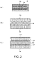
- FIG. 2 is a sectional view illustrating a configuration inside the heater 10.
- the heater 10 is configured of an insulating body 10i and a coil-shaped heat generating resistance wire lOr incorporated in the insulating body 10i.
- the heat generating resistance wire 10r is covered with the insulating body 10i in an initial state as illustrated in (B) of FIG. 2
- an oxide film 10f forms on the surface of the heat generating resistance wire 10r as illustrated in (C) of FIG. 2 due to aging, and a diameter of a power distribution part of the heat generating resistance wire 10r becomes thinner in accordance with the aging. If the oxide film 10f becomes thicker due to such aging, and the power distribution part of the heat generating resistance wire 10r becomes thinner, disconnection may eventually occur.
- a heater resistance value of the heater 10 varies due to aging. In other words, a rate of change from an initial state gradually changes. In addition, the system gain also varies due to a change in resistance value of the heater 10.
- FIG. 3 and (B) of FIG. 3 are sectional views illustrating an example of "loosening" of the heater 10 and the like configured to heat the item to be heated 1.
- the heater (band heater) 10 is wound around an outer periphery of the item to be heated 1 in a close contact state as illustrated in (A) of FIG. 3 .
- the outer periphery of the heater 10 is covered with a cover 10c that covers the heater 10.
- (B) of FIG. 3 is an example of a failure in which a gap is generated between the outer periphery of the item to be heated 1 and the heater 10 and a gap is also generated between the heater 10 and the cover 10c.
- the system gain which will be described later, varies due to a change "loosening" in an attachment state of the heater 10 and an attachment state of the cover.
- the system gain may vary from the initial state with utilization of the heating device.
- FIG. 4 and (B) of FIG. 4 are sectional views illustrating an example of "loosening" of a sleeve that covers the temperature detection unit 20.
- the temperature detection unit 20 is, for example, a thermocouple. In a normal situation, a leading end of the temperature detection unit 20 is in close contact with a sleeve 20s as illustrated in (A) of FIG. 4 .
- (B) of FIG. 4 is an example of a failure in which a gap is generated between the leading end of the temperature detection unit 20 and the sleeve 20s.
- the system gain which will be described later, varies due to a change "loosening" in a state of an attachment portion of the temperature detection unit 20.
- the system gain may vary from the initial state with utilization of the heating device.
- FIG. 5 is a diagram illustrating an example of a change in temperature of the item to be heated 1, and a change in the amount of operation of the heater 10 with elapse of time.
- the temperature of the item to be heated 1 rises from an ordinary temperature (initial temperature) to a target temperature (stable temperature) with elapse of time. Meanwhile, the amount of operation of the heater 10 starts from 100%, decreases with elapse of time, and stabilizes at a stable amount of operation.
- a system gain K is represented by the following equation since the system gain is a ratio of the temperature increase value of the item to be heated 1 with respect to the electric power inputted to the heater 10.
- K ⁇ PV / MV
- FIG. 6 is a block diagram illustrating details of an arithmetic operation performed as the system gain change rate calculation unit, an arithmetic operation performed as the heater resistance value change rate calculation unit, an arithmetic operation performed as the heater voltage change rate calculation unit, and an arithmetic operation performed as the heat-retaining property change rate calculation unit.
- K' the system gain at a timing at which the system gain change rate is obtained
- the rate of change in gain related to the heat transmission coefficient between the item to be heated 1 and the temperature detection unit 20 is represented as a
- the rate of change in heater voltage is represented as b
- the rate of change in heater resistance value is represented as c
- the system gain K' after a variation is represented by the following equation.
- K ′ aB ⁇ bV 2 / cR
- the rate of change a in heat-retaining properties is obtained from the system gain change rate d, the heater resistance value change rate c, and the heater voltage change rate b.
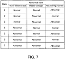
- FIG. 7 is a diagram illustrating a combination of abnormal states of the heating device 100. Since there are three failures, namely a failure in the resistance value of the heater 10, a failure in heater voltage, and a failure in heat-retaining properties of the item to be heated, in the heating device 100, there are seven combinations of abnormal states.
- the resistance value of the heater 10 is regarded as being "abnormal" in a state in which the heater resistance value change rate c exceeds a predetermined threshold.
- c > 1.2 for example, the heater resistance value is regarded as being abnormal.
- the heater voltage is regarded as being "abnormal" in a state in which the heater voltage change rate b exceeds a predetermined threshold value.
- the heater voltage is regarded as being abnormal when b ⁇ 0.9 or b > 1.1.
- the heat-retaining properties are regarded as being "abnormal" in a state in which the rate of change a in heat-retaining properties exceeds a predetermined threshold value.
- the heat-retaining properties are regarded as being abnormal when a ⁇ 0.74.
- a system gain at a timing at which the target temperature is reset may be defined as an initial value of the system gain
- a resistance value of the heater at that timing may be defined as an initial value of the heater resistance value
- a heater voltage at that timing may be defined as an initial value of the heater voltage.
Landscapes
- Physics & Mathematics (AREA)
- General Physics & Mathematics (AREA)
- Engineering & Computer Science (AREA)
- Automation & Control Theory (AREA)
- Control Of Resistance Heating (AREA)
Abstract
Description
- The present invention relates to a heating device that includes a heater configured to heat an item to be heated, a temperature detection unit configured to detect a temperature of the item to be heated, and a temperature adjustment unit configured to control the heater. Also, the invention relates to a method for detecting a failure in a heating device.
- In the related art, a method for detecting a failure in a feedback system on the basis of an actual temperature measurement value in a temperature control loop and a temperature prediction value predicted using a model has been proposed as a technology for detecting a failure in a heating device. For example,
Patent Literature 1 discloses a method of determining a state of a control target with reference to a behavior in a control transient state, a representative example of which is a step response. - [Patent Literature 1] Japanese Patent No.
4481953 - According to a method for determining a state of a control target on the basis of a behavior of a feedback system when a transient state is caused to occur as disclosed in
Patent Literature 1, it is not possible to detect how much the respective changes related to heat-retaining properties of an item to be heated have occurred. - Thus, an objective of the invention is to provide a heating device and a failure detecting method of a heating device capable of detecting a change related to heat-retaining properties of an item to be heated.
- As an example of the disclosure, there is provided a heating device that includes a heater configured to heat an item to be heated, a temperature detection unit configured to detect a temperature of the item to be heated, and a temperature adjustment unit configured to control the heater on the basis of a detected value of the temperature detection unit and a target temperature so that the temperature of the item to be heated reaches the target temperature, the heating device including; a system gain change rate calculation unit configured to obtain a temperature increase value of the item to be heated from the detected value of the temperature detection unit, obtain a system gain, which is a ratio of the temperature increase value of the item to be heated with respect to electric power inputted to the heater, and obtain, as a system gain change rate, a rate of change from an initial value of the system gain; and a heat-retaining property change rate calculation unit configured to obtain a rate of change in heat-retaining properties of the item to be heated from the system gain change rate.
- With this configuration, it is possible to detect a change related to heat-retaining properties of the item to be heated.
- Also, in the example of the disclosure, the heating device further includes: a heater resistance value change rate calculation unit configured to obtain a resistance value of the heater from a voltage and a current applied to the heater and obtain, as a heater resistance value change rate, a rate of change from an initial value of the resistance value, and the heat-retaining property change rate calculation unit obtains the rate of change in heat-retaining properties of the item to be heated from the system gain change rate and the heater resistance value change rate.
- With this configuration. it is possible to detect deterioration of the heater in the heating device and a change related to heat-retaining properties of the item to be heated.
- In addition, in the example of the disclosure, the heating device further includes: a heater voltage change rate calculation unit configured to obtain, as a heater voltage change rate, a rate of change from an initial value of a voltage applied to the heater, and the heat-retaining property change rate calculation unit obtains the rate of change in heat-retaining properties of the item to be heated from the system gain change rate and the heater voltage change rate.
- With this configuration, it is possible to detect a variation in voltage applied to the heater and a change related to heat-retaining properties of the item to be heated.
- Also, in the example of the disclosure, the heating device further includes: a heater voltage change rate calculation unit configured to obtain, as a heater voltage change rate, a rate of change from an initial value of a voltage applied to the heater, and the heat-retaining property change rate calculation unit obtains the rate of change in heat-retaining properties of the item to be heated from the system gain change rate, the heater resistance value change rate, and the heater voltage change rate.
- With this configuration, it is possible to detect deterioration of the heater in the heating device, a variation in voltage applied to the heater, and a change related to heat-retaining properties of the item to be heated.
- Also, in the example of the disclosure, the heating device further includes: a heat-retaining property failure detection unit configured to detect a failure in the heat-retaining properties by comparing the heat-retaining property change rate with a threshold for the heat-retaining property change rate. With this configuration, it is possible to detect a failure related to heat-retaining properties of the item to be heated.
- Also, in the example of the disclosure, the heating device further includes: a heater resistance value failure detection unit configured to detect a failure in the resistance value of the heater by comparing the heater resistance value change rate with a threshold value for the heater resistance value change rate. With this configuration, it is possible to detect a failure in the resistance value of the heater.
- Also, in the example of the disclosure, the heating device further includes: a heater voltage failure detection unit configured to detect a failure in the voltage applied to the heater by comparing the heater voltage change rate with a threshold value for the heater voltage change rate. With this configuration, it is possible to detect a failure in voltage applied to the heater.
- Also, according to an example of the disclosure, there is provided a failure detecting method of a heating device that includes a heater configured to heat an item to be heated, a temperature detection unit configured to detect a temperature of the item to be heated, and a temperature adjustment unit configured to control the heater on the basis of a detected value of the temperature detection unit and a target temperature so that the temperature of the item to be heated reaches the target temperature, the failure detecting method including: obtaining a temperature increase value of the item to be heated from the detected value of the temperature detection unit, obtaining a system gain, which is a ratio of the temperature increase value of the item to be heated with respect to electric power inputted to the heater, and obtaining, as a system gain change rate, a rate of change from an initial value of the system gain; and obtaining a rate of change in heat-retaining properties of the item to be heated from the system gain change rate and detecting a failure in the heating device depending on whether or not the rate of change in heat-retaining properties exceeds a threshold value.
- With this configuration, it is possible to detect a change related to heat-retaining properties of the item to be heated and a failure in heating device.
- According to the invention, it is possible to detect a change related to heat-retaining properties of the item to be heated.
-
-
FIG. 1 is a diagram illustrating a configuration of aheating device 100 according to an embodiment of the invention. - (A) of
FIG. 2 is a sectional view illustrating a configuration inside aheater 10. (B) ofFIG. 2 and (C) ofFIG. 2 are enlarged sectional views illustrating a configuration inside theheater 10. - (A) of
FIG. 3 and (B) ofFIG. 3 are sectional views illustrating an example of "loosening" of theheater 10 and the like that heat an item to be heated 1. - (A) of
FIG. 4 and (B) ofFIG. 4 are sectional views illustrating an example of "loosening" of a sleeve that covers atemperature detection unit 20. -
FIG. 5 is a diagram illustrating an example of a change in temperature of the item to be heated 1 and a change in the amount of operation of theheater 10. -
FIG. 6 is a block diagram illustrating details of an arithmetic operation performed as a system gain change rate calculation unit, an arithmetic operation performed as a heater resistance value change rate calculation unit, an arithmetic operation performed as a heater voltage change rate calculation unit, and an arithmetic operation performed as a heat-retaining property change rate calculation unit. -
FIG. 7 is a diagram illustrating a combination of abnormal states of theheating device 100. - Hereinafter, an embodiment for carrying out the invention will be described with reference to some drawings.
- First, an example to which the invention is applied will be described with reference to
FIG. 1. FIG. 1 is a diagram illustrating a configuration of aheating device 100 according to an embodiment of the invention. - As illustrated in
FIG. 1 , theheating device 100 according to the embodiment includes aheater 10 configured to heat an item to be heated 1, atemperature detection unit 20 configured to detect a temperature of the item to be heated 1, and atemperature adjustment unit 30 configured to control theheater 10 such that the temperature of the item to be heated 1 reaches a target temperature on the basis of a detected value of thetemperature detection unit 20 and the target temperature. - The
temperature adjustment unit 30 includes a system gain change rate calculation unit, a heater resistance value change rate calculation unit, a heater voltage change rate calculation unit, and a heat-retaining property change rate calculation unit. The system gain change rate calculation unit obtains a temperature increase value of the item to be heated 1 from the detected value of thetemperature detection unit 20, obtains a system gain, which is a ratio of the temperature increase value of the item to be heated 1 with respect to electric power inputted to theheater 10, and obtains a rate of change from an initial value of the system gain. The heater resistance value change rate calculation unit obtains a resistance value of theheater 10 from a voltage and a current applied to theheater 10 and obtains a rate of change from an initial value of the resistance value. The heater voltage change rate calculation unit obtains a rate of change in voltage applied to theheater 10 from an initial value thereof. Also, the heat-retaining property change rate calculation unit obtains a rate of change in heat-retaining properties of the item to be heated from the system gain change rate, the heater resistance value change rate, and the heater voltage change rate. - Next, a configuration of the heating device according to the embodiment of the invention will be described with reference to the drawing. As described above,
FIG. 1 is a diagram illustrating a configuration of theheating device 100 according to the embodiment of the invention. - As represented in
FIG. 1 , theheating device 100 includes theheater 10 configured to heat the item to be heated 1, thetemperature detection unit 20 configured to detect the temperature of the item to be heated 1, thetemperature adjustment unit 30 configured to control theheater 10 on the basis of the detected value of thetemperature detection unit 20 and the target temperature, asolid state switch 40, aheater power supply 50, avoltage detection unit 60 configured to detect a voltage applied to the heater, and acurrent detection unit 70 configured to detect a current flowing through theheater 10. The item to be heated 1 is a molded article of metal or the like. SinceFIG. 1 is a block configuration diagram and the item to be heated 1 is conceptually illustrated, an actual shape thereof is appropriately defined. - The item to be heated 1 is a heating unit of a packaging machine configured to heat a resin and package an article, for example. The
heater 10 and thetemperature detection unit 20 are provided in the heating unit. - The
temperature adjustment unit 30 includes a voltage-temperature conversion unit 31 configured to convert a voltage output from thetemperature detection unit 20 into a temperature information signal, an operation amount-PWM conversion unit 32 configured to perform PWM control on thesolid state switch 40, and an operationamount conversion unit 33. The operationamount conversion unit 33 is a PID controller and obtains the amount of operation through PID control on the basis of temperature information and target temperature information obtained by the voltage-temperature conversion unit 31. - In addition, the operation
amount conversion unit 33 performs an arithmetic operation as the system gain change rate calculation unit, an arithmetic operation as the heater resistance value change rate calculation unit, an arithmetic operation as the heater voltage change rate calculation unit, and an arithmetic operation as the heat-retaining property change rate calculation unit. These arithmetic operations will be described in detail below. - (A) of
FIG. 2 is a sectional view illustrating a configuration inside theheater 10. Theheater 10 is configured of aninsulating body 10i and a coil-shaped heat generating resistance wire lOr incorporated in theinsulating body 10i. Although the heat generatingresistance wire 10r is covered with the insulatingbody 10i in an initial state as illustrated in (B) ofFIG. 2 , anoxide film 10f forms on the surface of the heat generatingresistance wire 10r as illustrated in (C) ofFIG. 2 due to aging, and a diameter of a power distribution part of the heat generatingresistance wire 10r becomes thinner in accordance with the aging. If theoxide film 10f becomes thicker due to such aging, and the power distribution part of the heat generatingresistance wire 10r becomes thinner, disconnection may eventually occur. - As illustrated in (A) of
FIG. 2 and (B) ofFIG 2 , a heater resistance value of theheater 10 varies due to aging. In other words, a rate of change from an initial state gradually changes. In addition, the system gain also varies due to a change in resistance value of theheater 10. - (A) of
FIG. 3 and (B) ofFIG. 3 are sectional views illustrating an example of "loosening" of theheater 10 and the like configured to heat the item to be heated 1. In a normal situation, the heater (band heater) 10 is wound around an outer periphery of the item to be heated 1 in a close contact state as illustrated in (A) ofFIG. 3 . Also, the outer periphery of theheater 10 is covered with acover 10c that covers theheater 10. (B) ofFIG. 3 is an example of a failure in which a gap is generated between the outer periphery of the item to be heated 1 and theheater 10 and a gap is also generated between theheater 10 and thecover 10c. - In this manner, the system gain, which will be described later, varies due to a change "loosening" in an attachment state of the
heater 10 and an attachment state of the cover. In other words, the system gain may vary from the initial state with utilization of the heating device. - (A) of
FIG. 4 and (B) ofFIG. 4 are sectional views illustrating an example of "loosening" of a sleeve that covers thetemperature detection unit 20. Thetemperature detection unit 20 is, for example, a thermocouple. In a normal situation, a leading end of thetemperature detection unit 20 is in close contact with asleeve 20s as illustrated in (A) ofFIG. 4 . (B) ofFIG. 4 is an example of a failure in which a gap is generated between the leading end of thetemperature detection unit 20 and thesleeve 20s. - In this manner, the system gain, which will be described later, varies due to a change "loosening" in a state of an attachment portion of the
temperature detection unit 20. In other words, the system gain may vary from the initial state with utilization of the heating device. -
FIG. 5 is a diagram illustrating an example of a change in temperature of the item to be heated 1, and a change in the amount of operation of theheater 10 with elapse of time. The temperature of the item to be heated 1 rises from an ordinary temperature (initial temperature) to a target temperature (stable temperature) with elapse of time. Meanwhile, the amount of operation of theheater 10 starts from 100%, decreases with elapse of time, and stabilizes at a stable amount of operation. - Here, if (the target temperature - ordinary temperature) is represented as ΔPV, and the stable amount of operation is represented as MV, a system gain K is represented by the following equation since the system gain is a ratio of the temperature increase value of the item to be heated 1 with respect to the electric power inputted to the
heater 10.
-
FIG. 6 is a block diagram illustrating details of an arithmetic operation performed as the system gain change rate calculation unit, an arithmetic operation performed as the heater resistance value change rate calculation unit, an arithmetic operation performed as the heater voltage change rate calculation unit, and an arithmetic operation performed as the heat-retaining property change rate calculation unit. - Here, if the gain related to a heat transmission coefficient between the item to be heated 1 and the
temperature detection unit 20 is represented as B, the voltage applied to theheater 10 is represented as V, and the resistance value of theheater 10 is represented as R, the system gain K is also represented by the following equation.
- The resistance value R of the
heater 10 is obtained by
- If the system gain at a timing at which the system gain change rate is obtained is represented as K', the rate of change in gain related to the heat transmission coefficient between the item to be heated 1 and the
temperature detection unit 20 is represented as a, the rate of change in heater voltage is represented as b, and the rate of change in heater resistance value is represented as c, the system gain K' after a variation is represented by the following equation.
- Also, if the initial system gain is represented as K, and the system gain at the timing at which the system gain change rate is obtained is represented as K', the system gain change rate d is represented by the following equation.

- In addition, it is possible to state that the rate of change a in the gain related to the heat transmission coefficient between the item to be heated 1 and the
temperature detection unit 20 is a rate of change in heat-retaining properties of the item to be heated 1. Therefore, it is possible to obtain the rate of change a in heat-retaining properties using the following equation.
- An arithmetic operation performed by the operation
amount conversion unit 33 illustrated inFIG. 1 as the heater resistance value change rate calculation unit is as follows. - If an initial resistance value of the
heater 10 is represented as R, and a resistance value at a timing at which the heater resistance change rate is obtained is represented as R', the heater resistance value change rate calculation unit obtains the heater resistance value change rate c using the following equation.
- In addition, an arithmetic operation performed as the heater voltage change rate calculation unit is as follows.
- If an initial voltage applied to the
heater 10 is represented as V, and a voltage at the timing at which the heater voltage change rate is obtained is represented as V', the heater voltage change rate calculation unit obtains the heater voltage change rate b using the following equation.
- In addition, the rate of change a in heat-retaining properties is obtained from the system gain change rate d, the heater resistance value change rate c, and the heater voltage change rate b.
- As illustrated in
FIG. 6 , it is possible to recognize that if d = 0.5, c = 1.2, and b = 0.9, for example, the rate of change a in heat-retaining properties is 0.74, that is, a state in which the heat-retaining properties have dropped by 26% has been achieved. -
FIG. 7 is a diagram illustrating a combination of abnormal states of theheating device 100. Since there are three failures, namely a failure in the resistance value of theheater 10, a failure in heater voltage, and a failure in heat-retaining properties of the item to be heated, in theheating device 100, there are seven combinations of abnormal states. - The resistance value of the
heater 10 is regarded as being "abnormal" in a state in which the heater resistance value change rate c exceeds a predetermined threshold. When c > 1.2, for example, the heater resistance value is regarded as being abnormal. - Also, the heater voltage is regarded as being "abnormal" in a state in which the heater voltage change rate b exceeds a predetermined threshold value. For example, the heater voltage is regarded as being abnormal when b < 0.9 or b > 1.1.
- Also, the heat-retaining properties are regarded as being "abnormal" in a state in which the rate of change a in heat-retaining properties exceeds a predetermined threshold value. For example, the heat-retaining properties are regarded as being abnormal when a < 0.74.
- In this manner, any of the abnormal states can individually be detected.
- Also, there is a concern that in a case in which properties (system gain) of the heating device, that is, the heater voltage, the heater resistance value, the heat-retaining properties, and the like have varied, temperature control performance may be degraded due to the variations. However, in a state in which the given heater voltage change rate, the heater resistance value change rate, and the rate of change in heat-retaining properties are small, it is possible to maintain the temperature control performance by calculating a proportional band (P in PID control) again from the new heater voltage, heater resistance value, and heat-retaining properties.
- Finally, it is a matter of course that the above description of the embodiment for carrying out the invention has been provided only for illustrative purposes in terms of all points and is not intended to be restrictive. It is possible for those skilled in the art to appropriately add modifications and changes. Although the amount of variation from the initial value is obtained for each parameter to detect a failure in the aforementioned example, for example, it is not necessary to fix at which point a value is defined as the initial value. For example, a system gain at a timing at which the target temperature is reset may be defined as an initial value of the system gain, a resistance value of the heater at that timing may be defined as an initial value of the heater resistance value, and a heater voltage at that timing may be defined as an initial value of the heater voltage.
-
- 1
- Item to be heated
- 10
- Heater
- 10c
- Cover
- 10f
- Oxide film
- 10i
- Insulating body
- 10r
- Heat generating resistance wire
- 20
- Temperature detection unit
- 20f
- Oxide film
- 20s
- Sleeve
- 30
- Temperature adjustment unit
- 31
- Temperature conversion unit
- 32
- Operation amount-PMW conversion unit
- 33
- Operation amount conversion unit
- 40
- Solid state switch
- 50
- Heater power supply
- 60
- Heater voltage detection unit
- 70
- Heater current detection unit
- 100
- Heating device
Claims (8)
- A heating device that includes a heater configured to heat an item to be heated, a temperature detection unit configured to detect a temperature of the item to be heated, and a temperature adjustment unit configured to control the heater on the basis of a detected value of the temperature detection unit and a target temperature so that the temperature of the item to be heated reaches the target temperature, the heating device comprising:a system gain change rate calculation unit configured to obtain a temperature increase value of the item to be heated from the detected value of the temperature detection unit, obtain a system gain, which is a ratio of the temperature increase value of the item to be heated with respect to electric power inputted to the heater, and obtain, as a system gain change rate, a rate of change from an initial value of the system gain; anda heat-retaining property change rate calculation unit configured to obtain a rate of change in heat-retaining properties of the item to be heated from the system gain change rate.
- The heating device according to claim 1, further comprising:a heater resistance value change rate calculation unit configured to obtain a resistance value of the heater from a voltage and a current applied to the heater and obtain, as a heater resistance value change rate, a rate of change from an initial value of the resistance value,wherein the heat-retaining property change rate calculation unit obtains the rate of change in heat-retaining properties of the item to be heated from the system gain change rate and the heater resistance value change rate.
- The heating device according to claim 1, further comprising:a heater voltage change rate calculation unit configured to obtain, as a heater voltage change rate, a rate of change from an initial value of a voltage applied to the heater,wherein the heat-retaining property change rate calculation unit obtains the rate of change in heat-retaining properties of the item to be heated from the system gain change rate and the heater voltage change rate.
- The heating device according to claim 2, further comprising:a heater voltage change rate calculation unit configured to obtain, as a heater voltage change rate, a rate of change from an initial value of a voltage applied to the heater,wherein the heat-retaining property change rate calculation unit obtains the rate of change in heat-retaining properties of the item to be heated from the system gain change rate, the heater resistance value change rate, and the heater voltage change rate.
- The heating device according to any one of claims 1 to 4, further comprising:
a heat-retaining property failure detection unit configured to detect a failure in the heat-retaining properties by comparing the heat-retaining property change rate with a threshold for the heat-retaining property change rate. - The heating device according to claim 2 or 4, further comprising:
a heater resistance value failure detection unit configured to detect a failure in the resistance value of the heater by comparing the heater resistance value change rate with a threshold value for the heater resistance change rate. - The heating device according to claim 3 or 4, further comprising:
a heater voltage failure detection unit configured to detect a failure in the voltage applied to the heater by comparing the heater voltage change rate with a threshold value for the heater voltage change rate. - A failure detecting method of a heating device that includes a heater configured to heat an item to be heated, a temperature detection unit configured to detect a temperature of the item to be heated, and a temperature adjustment unit configured to control the heater on the basis of a detected value of the temperature detection unit and a target temperature so that the temperature of the item to be heated reaches the target temperature, the failure detecting method comprising:obtaining a temperature increase value of the item to be heated from the detected value of the temperature detection unit, obtaining a system gain, which is a ratio of the temperature increase value of the item to be heated with respect to electric power inputted to the heater, and obtaining, as a system gain change rate, a rate of change from an initial value of the system gain; andobtaining a rate of change in heat-retaining properties of the item to be heated from the system gain change rate and detecting a failure in the heating device depending on whether or not the rate of change in heat-retaining properties exceeds a threshold value.
Applications Claiming Priority (2)
| Application Number | Priority Date | Filing Date | Title |
|---|---|---|---|
| JP2018037074A JP6874719B2 (en) | 2018-03-02 | 2018-03-02 | Heating device and abnormality detection method for heating device |
| PCT/JP2019/001743 WO2019167473A1 (en) | 2018-03-02 | 2019-01-22 | Heating device and method for detecting failure of heating device |
Publications (3)
| Publication Number | Publication Date |
|---|---|
| EP3761757A1 true EP3761757A1 (en) | 2021-01-06 |
| EP3761757A4 EP3761757A4 (en) | 2021-11-24 |
| EP3761757B1 EP3761757B1 (en) | 2025-07-09 |
Family
ID=67805743
Family Applications (1)
| Application Number | Title | Priority Date | Filing Date |
|---|---|---|---|
| EP19760536.3A Active EP3761757B1 (en) | 2018-03-02 | 2019-01-22 | Heating device and method for detecting failure of heating device |
Country Status (6)
| Country | Link |
|---|---|
| US (1) | US11812522B2 (en) |
| EP (1) | EP3761757B1 (en) |
| JP (1) | JP6874719B2 (en) |
| CN (1) | CN111034352B (en) |
| TW (1) | TWI696054B (en) |
| WO (1) | WO2019167473A1 (en) |
Cited By (3)
| Publication number | Priority date | Publication date | Assignee | Title |
|---|---|---|---|---|
| EP4369859A4 (en) * | 2021-07-09 | 2025-07-02 | Omron Tateisi Electronics Co | ANOMALY DETERMINATION DEVICE, ANOMALY DETERMINATION METHOD AND ANOMALY DETERMINATION SYSTEM |
| EP4665085A1 (en) * | 2024-06-13 | 2025-12-17 | MULTIVAC Sepp Haggenmüller SE & Co. KG | Method and device for determining the functionality of a heating device for a packaging machine |
| EP4628814A3 (en) * | 2021-09-08 | 2025-12-31 | Baxter International Inc. | INLINE HEATING OVERHEATING SYSTEM AND METHOD |
Families Citing this family (4)
| Publication number | Priority date | Publication date | Assignee | Title |
|---|---|---|---|---|
| WO2021055412A1 (en) * | 2019-09-20 | 2021-03-25 | Nordson Corporation | Systems and methods for direct heater diagnostics for a hot melt liquid dispensing system |
| JP7694062B2 (en) * | 2021-03-04 | 2025-06-18 | オムロン株式会社 | Abnormality determination device |
| JP7771564B2 (en) * | 2021-07-09 | 2025-11-18 | オムロン株式会社 | Abnormality determination device, abnormality determination method, and abnormality determination system |
| CN117716793A (en) * | 2021-07-09 | 2024-03-15 | 欧姆龙株式会社 | Abnormality determination device, abnormality determination method, and abnormality determination system |
Family Cites Families (25)
| Publication number | Priority date | Publication date | Assignee | Title |
|---|---|---|---|---|
| US3315063A (en) * | 1964-05-07 | 1967-04-18 | Boeing Co | Temperature control system |
| GB2283583B (en) | 1993-10-15 | 1998-06-24 | Seiko Epson Corp | Temperature control in a fixing device for an image forming apparatus |
| JP3829575B2 (en) * | 2000-03-15 | 2006-10-04 | オムロン株式会社 | Temperature controller and heat treatment equipment |
| JP3911953B2 (en) * | 2000-03-15 | 2007-05-09 | オムロン株式会社 | Control device and temperature controller |
| JP3555609B2 (en) * | 2001-11-30 | 2004-08-18 | オムロン株式会社 | Control device, temperature controller and heat treatment device |
| JP2005228732A (en) | 2004-01-15 | 2005-08-25 | Omron Corp | Failure detection device |
| US7248808B2 (en) * | 2005-03-17 | 2007-07-24 | Kabushiki Kaisha Toshiba | Heating apparatus, heating apparatus control method and noncontact thermal sensing device |
| JP2006292535A (en) * | 2005-04-11 | 2006-10-26 | Omron Corp | Distance estimation device, abnormality detection device, temperature controller and heat treatment device |
| ITTO20050841A1 (en) * | 2005-11-29 | 2007-05-30 | Incos Spa | THERMOREGULATION SYSTEM FOR HEATED COMPONENTS OF PLASTIC INJECTION MOLDING EQUIPMENT |
| JP4481953B2 (en) * | 2006-04-24 | 2010-06-16 | 株式会社山武 | State determination device and state determination method |
| JP4818012B2 (en) * | 2006-07-25 | 2011-11-16 | 三洋電機株式会社 | Electric stove |
| JP2008217317A (en) * | 2007-03-02 | 2008-09-18 | Omron Corp | air conditioner |
| JP5231096B2 (en) * | 2008-06-20 | 2013-07-10 | アズビル株式会社 | Temperature control method and temperature control apparatus |
| KR101182502B1 (en) | 2008-09-30 | 2012-09-12 | 도쿄엘렉트론가부시키가이샤 | Method for detecting abnormal placement state of substrate, substrate processing method, computer-readable storage medium and substrate processing apparatus |
| TWM406757U (en) | 2010-09-14 | 2011-07-01 | Lnc Technology Co Ltd | Electric heat protection device |
| JP5411895B2 (en) * | 2011-06-14 | 2014-02-12 | 株式会社日立国際電気 | Heat treatment equipment for workpieces |
| JP5884390B2 (en) * | 2011-10-11 | 2016-03-15 | 株式会社デンソー | Heating device |
| JP6197359B2 (en) * | 2013-05-14 | 2017-09-20 | オムロン株式会社 | Simulation method, simulation program, simulation apparatus, and system |
| JP6292031B2 (en) | 2014-05-26 | 2018-03-14 | オムロン株式会社 | Control method, control device, program, and recording medium |
| JP5830156B1 (en) * | 2014-11-20 | 2015-12-09 | シャープ株式会社 | Liquid heater |
| BR112017018344B1 (en) | 2015-03-26 | 2022-02-22 | Philip Morris Products S.A | ELECTRICALLY OPERATED AEROSOL GENERATING SYSTEM, HEATER ASSEMBLY, ELECTRICALLY OPERATED AEROSOL GENERATING DEVICE, ELECTRICAL CIRCUIT, METHOD FOR CONTROLLING POWER SUPPLY TO A HEATER, METHOD FOR DETECTING AN INCOMPATIBLE OR DAMAGED HEATER AND COMPUTER PROGRAM PRODUCT |
| CN104955178B (en) * | 2015-05-12 | 2016-08-24 | 孙昊 | Heating means and heater |
| CN106248075B (en) * | 2016-09-19 | 2019-02-22 | 上海航天控制技术研究所 | A kind of star sensor precise temperature control device and control method |
| GB2569660B (en) * | 2017-12-22 | 2022-03-02 | Jemella Ltd | Thermal control apparatus and method |
| JP6874696B2 (en) * | 2018-01-09 | 2021-05-19 | オムロン株式会社 | Heating device |
-
2018
- 2018-03-02 JP JP2018037074A patent/JP6874719B2/en active Active
-
2019
- 2019-01-22 CN CN201980003938.XA patent/CN111034352B/en active Active
- 2019-01-22 WO PCT/JP2019/001743 patent/WO2019167473A1/en not_active Ceased
- 2019-01-22 US US16/639,551 patent/US11812522B2/en active Active
- 2019-01-22 EP EP19760536.3A patent/EP3761757B1/en active Active
- 2019-01-23 TW TW108102538A patent/TWI696054B/en active
Cited By (3)
| Publication number | Priority date | Publication date | Assignee | Title |
|---|---|---|---|---|
| EP4369859A4 (en) * | 2021-07-09 | 2025-07-02 | Omron Tateisi Electronics Co | ANOMALY DETERMINATION DEVICE, ANOMALY DETERMINATION METHOD AND ANOMALY DETERMINATION SYSTEM |
| EP4628814A3 (en) * | 2021-09-08 | 2025-12-31 | Baxter International Inc. | INLINE HEATING OVERHEATING SYSTEM AND METHOD |
| EP4665085A1 (en) * | 2024-06-13 | 2025-12-17 | MULTIVAC Sepp Haggenmüller SE & Co. KG | Method and device for determining the functionality of a heating device for a packaging machine |
Also Published As
| Publication number | Publication date |
|---|---|
| JP2019153437A (en) | 2019-09-12 |
| EP3761757A4 (en) | 2021-11-24 |
| JP6874719B2 (en) | 2021-05-19 |
| US11812522B2 (en) | 2023-11-07 |
| TW201939182A (en) | 2019-10-01 |
| EP3761757B1 (en) | 2025-07-09 |
| CN111034352A (en) | 2020-04-17 |
| US20210136872A1 (en) | 2021-05-06 |
| CN111034352B (en) | 2021-10-19 |
| TWI696054B (en) | 2020-06-11 |
| WO2019167473A1 (en) | 2019-09-06 |
Similar Documents
| Publication | Publication Date | Title |
|---|---|---|
| EP3761757B1 (en) | Heating device and method for detecting failure of heating device | |
| US10340774B2 (en) | Temperature estimating device of electric motor | |
| US11248966B2 (en) | Health monitoring and failure prognosis of power electronics devices | |
| US8767367B2 (en) | Wire protection method and wire protection device | |
| EP3109607B1 (en) | Method for temperature drift compensation of temperature measurement device using thermocouple | |
| US20120123762A1 (en) | Thermal Memory In A Fault Powered System | |
| EP3691406B1 (en) | Seat heater, method for controlling temperature of seat heater, and temperature control program | |
| TWI743739B (en) | Thermal system with a temperature limiting device | |
| WO2019105132A1 (en) | Internal heating of battery | |
| KR101849509B1 (en) | Adjustment device, control method, and medium of control program | |
| JP2009210282A (en) | Temperature measuring device, temperature measuring method, and abnormality detection method of temperature measuring device | |
| JP6070145B2 (en) | Controller, operation amount output method, program, and storage medium | |
| EP3348978B1 (en) | Temperature measurement device using thermocouple | |
| JP2009226984A (en) | Electric wire protection method and electric wire protection device | |
| KR101543000B1 (en) | System and method for water temperature sensor management of green car | |
| KR101977137B1 (en) | braking apparatus for a generator | |
| KR20120097927A (en) | A method for estimating battery temperature of a vehicle | |
| JP5537363B2 (en) | Protective relay | |
| CN121790221A (en) | A relay control method based on temperature sensing | |
| CN205427658U (en) | Nuclear power station cooling water set pipeline heating control system | |
| CN118017641A (en) | Current feedback regulation method, device, equipment and storage medium |
Legal Events
| Date | Code | Title | Description |
|---|---|---|---|
| STAA | Information on the status of an ep patent application or granted ep patent |
Free format text: STATUS: THE INTERNATIONAL PUBLICATION HAS BEEN MADE |
|
| PUAI | Public reference made under article 153(3) epc to a published international application that has entered the european phase |
Free format text: ORIGINAL CODE: 0009012 |
|
| STAA | Information on the status of an ep patent application or granted ep patent |
Free format text: STATUS: REQUEST FOR EXAMINATION WAS MADE |
|
| 17P | Request for examination filed |
Effective date: 20200217 |
|
| AK | Designated contracting states |
Kind code of ref document: A1 Designated state(s): AL AT BE BG CH CY CZ DE DK EE ES FI FR GB GR HR HU IE IS IT LI LT LU LV MC MK MT NL NO PL PT RO RS SE SI SK SM TR |
|
| AX | Request for extension of the european patent |
Extension state: BA ME |
|
| DAV | Request for validation of the european patent (deleted) | ||
| DAX | Request for extension of the european patent (deleted) | ||
| REG | Reference to a national code |
Ref country code: DE Ref legal event code: R079 Free format text: PREVIOUS MAIN CLASS: H05B0003000000 Ipc: H05B0001020000 Ref document number: 602019072303 Country of ref document: DE |
|
| A4 | Supplementary search report drawn up and despatched |
Effective date: 20211022 |
|
| RIC1 | Information provided on ipc code assigned before grant |
Ipc: H05B 1/02 20060101AFI20211018BHEP |
|
| STAA | Information on the status of an ep patent application or granted ep patent |
Free format text: STATUS: EXAMINATION IS IN PROGRESS |
|
| 17Q | First examination report despatched |
Effective date: 20220912 |
|
| GRAP | Despatch of communication of intention to grant a patent |
Free format text: ORIGINAL CODE: EPIDOSNIGR1 |
|
| STAA | Information on the status of an ep patent application or granted ep patent |
Free format text: STATUS: GRANT OF PATENT IS INTENDED |
|
| INTG | Intention to grant announced |
Effective date: 20250214 |
|
| GRAS | Grant fee paid |
Free format text: ORIGINAL CODE: EPIDOSNIGR3 |
|
| GRAA | (expected) grant |
Free format text: ORIGINAL CODE: 0009210 |
|
| STAA | Information on the status of an ep patent application or granted ep patent |
Free format text: STATUS: THE PATENT HAS BEEN GRANTED |
|
| AK | Designated contracting states |
Kind code of ref document: B1 Designated state(s): AL AT BE BG CH CY CZ DE DK EE ES FI FR GB GR HR HU IE IS IT LI LT LU LV MC MK MT NL NO PL PT RO RS SE SI SK SM TR |
|
| REG | Reference to a national code |
Ref country code: GB Ref legal event code: FG4D |
|
| REG | Reference to a national code |
Ref country code: CH Ref legal event code: EP |
|
| REG | Reference to a national code |
Ref country code: IE Ref legal event code: FG4D |
|
| REG | Reference to a national code |
Ref country code: DE Ref legal event code: R096 Ref document number: 602019072303 Country of ref document: DE |
|
| REG | Reference to a national code |
Ref country code: NL Ref legal event code: MP Effective date: 20250709 |
|
| PG25 | Lapsed in a contracting state [announced via postgrant information from national office to epo] |
Ref country code: PT Free format text: LAPSE BECAUSE OF FAILURE TO SUBMIT A TRANSLATION OF THE DESCRIPTION OR TO PAY THE FEE WITHIN THE PRESCRIBED TIME-LIMIT Effective date: 20251110 |
|
| PG25 | Lapsed in a contracting state [announced via postgrant information from national office to epo] |
Ref country code: NL Free format text: LAPSE BECAUSE OF FAILURE TO SUBMIT A TRANSLATION OF THE DESCRIPTION OR TO PAY THE FEE WITHIN THE PRESCRIBED TIME-LIMIT Effective date: 20250709 |
|
| REG | Reference to a national code |
Ref country code: AT Ref legal event code: MK05 Ref document number: 1813093 Country of ref document: AT Kind code of ref document: T Effective date: 20250709 |
|
| PG25 | Lapsed in a contracting state [announced via postgrant information from national office to epo] |
Ref country code: IS Free format text: LAPSE BECAUSE OF FAILURE TO SUBMIT A TRANSLATION OF THE DESCRIPTION OR TO PAY THE FEE WITHIN THE PRESCRIBED TIME-LIMIT Effective date: 20251109 |
|
| PG25 | Lapsed in a contracting state [announced via postgrant information from national office to epo] |
Ref country code: NO Free format text: LAPSE BECAUSE OF FAILURE TO SUBMIT A TRANSLATION OF THE DESCRIPTION OR TO PAY THE FEE WITHIN THE PRESCRIBED TIME-LIMIT Effective date: 20251009 |
|
| REG | Reference to a national code |
Ref country code: LT Ref legal event code: MG9D |
|
| PG25 | Lapsed in a contracting state [announced via postgrant information from national office to epo] |
Ref country code: AT Free format text: LAPSE BECAUSE OF FAILURE TO SUBMIT A TRANSLATION OF THE DESCRIPTION OR TO PAY THE FEE WITHIN THE PRESCRIBED TIME-LIMIT Effective date: 20250709 |
|
| PG25 | Lapsed in a contracting state [announced via postgrant information from national office to epo] |
Ref country code: FI Free format text: LAPSE BECAUSE OF FAILURE TO SUBMIT A TRANSLATION OF THE DESCRIPTION OR TO PAY THE FEE WITHIN THE PRESCRIBED TIME-LIMIT Effective date: 20250709 |
|
| PG25 | Lapsed in a contracting state [announced via postgrant information from national office to epo] |
Ref country code: HR Free format text: LAPSE BECAUSE OF FAILURE TO SUBMIT A TRANSLATION OF THE DESCRIPTION OR TO PAY THE FEE WITHIN THE PRESCRIBED TIME-LIMIT Effective date: 20250709 |
|
| PG25 | Lapsed in a contracting state [announced via postgrant information from national office to epo] |
Ref country code: GR Free format text: LAPSE BECAUSE OF FAILURE TO SUBMIT A TRANSLATION OF THE DESCRIPTION OR TO PAY THE FEE WITHIN THE PRESCRIBED TIME-LIMIT Effective date: 20251010 |
|
| PG25 | Lapsed in a contracting state [announced via postgrant information from national office to epo] |
Ref country code: SE Free format text: LAPSE BECAUSE OF FAILURE TO SUBMIT A TRANSLATION OF THE DESCRIPTION OR TO PAY THE FEE WITHIN THE PRESCRIBED TIME-LIMIT Effective date: 20250709 |
|
| PG25 | Lapsed in a contracting state [announced via postgrant information from national office to epo] |
Ref country code: LV Free format text: LAPSE BECAUSE OF FAILURE TO SUBMIT A TRANSLATION OF THE DESCRIPTION OR TO PAY THE FEE WITHIN THE PRESCRIBED TIME-LIMIT Effective date: 20250709 |
|
| PG25 | Lapsed in a contracting state [announced via postgrant information from national office to epo] |
Ref country code: BG Free format text: LAPSE BECAUSE OF FAILURE TO SUBMIT A TRANSLATION OF THE DESCRIPTION OR TO PAY THE FEE WITHIN THE PRESCRIBED TIME-LIMIT Effective date: 20250709 Ref country code: PL Free format text: LAPSE BECAUSE OF FAILURE TO SUBMIT A TRANSLATION OF THE DESCRIPTION OR TO PAY THE FEE WITHIN THE PRESCRIBED TIME-LIMIT Effective date: 20250709 |
|
| PG25 | Lapsed in a contracting state [announced via postgrant information from national office to epo] |
Ref country code: RS Free format text: LAPSE BECAUSE OF FAILURE TO SUBMIT A TRANSLATION OF THE DESCRIPTION OR TO PAY THE FEE WITHIN THE PRESCRIBED TIME-LIMIT Effective date: 20251009 |
|
| PG25 | Lapsed in a contracting state [announced via postgrant information from national office to epo] |
Ref country code: ES Free format text: LAPSE BECAUSE OF FAILURE TO SUBMIT A TRANSLATION OF THE DESCRIPTION OR TO PAY THE FEE WITHIN THE PRESCRIBED TIME-LIMIT Effective date: 20250709 |
|
| PG25 | Lapsed in a contracting state [announced via postgrant information from national office to epo] |
Ref country code: SM Free format text: LAPSE BECAUSE OF FAILURE TO SUBMIT A TRANSLATION OF THE DESCRIPTION OR TO PAY THE FEE WITHIN THE PRESCRIBED TIME-LIMIT Effective date: 20250709 |
|
| REG | Reference to a national code |
Ref country code: DE Ref legal event code: R097 Ref document number: 602019072303 Country of ref document: DE |
|
| PG25 | Lapsed in a contracting state [announced via postgrant information from national office to epo] |
Ref country code: DK Free format text: LAPSE BECAUSE OF FAILURE TO SUBMIT A TRANSLATION OF THE DESCRIPTION OR TO PAY THE FEE WITHIN THE PRESCRIBED TIME-LIMIT Effective date: 20250709 |
|
| PG25 | Lapsed in a contracting state [announced via postgrant information from national office to epo] |
Ref country code: IT Free format text: LAPSE BECAUSE OF FAILURE TO SUBMIT A TRANSLATION OF THE DESCRIPTION OR TO PAY THE FEE WITHIN THE PRESCRIBED TIME-LIMIT Effective date: 20250709 |
|
| PG25 | Lapsed in a contracting state [announced via postgrant information from national office to epo] |
Ref country code: CZ Free format text: LAPSE BECAUSE OF FAILURE TO SUBMIT A TRANSLATION OF THE DESCRIPTION OR TO PAY THE FEE WITHIN THE PRESCRIBED TIME-LIMIT Effective date: 20250709 |
|
| PG25 | Lapsed in a contracting state [announced via postgrant information from national office to epo] |
Ref country code: EE Free format text: LAPSE BECAUSE OF FAILURE TO SUBMIT A TRANSLATION OF THE DESCRIPTION OR TO PAY THE FEE WITHIN THE PRESCRIBED TIME-LIMIT Effective date: 20250709 Ref country code: SK Free format text: LAPSE BECAUSE OF FAILURE TO SUBMIT A TRANSLATION OF THE DESCRIPTION OR TO PAY THE FEE WITHIN THE PRESCRIBED TIME-LIMIT Effective date: 20250709 |
|
| PLBE | No opposition filed within time limit |
Free format text: ORIGINAL CODE: 0009261 |
|
| STAA | Information on the status of an ep patent application or granted ep patent |
Free format text: STATUS: NO OPPOSITION FILED WITHIN TIME LIMIT |
|
| REG | Reference to a national code |
Ref country code: CH Ref legal event code: L10 Free format text: ST27 STATUS EVENT CODE: U-0-0-L10-L00 (AS PROVIDED BY THE NATIONAL OFFICE) Effective date: 20260521 |
|
| 26N | No opposition filed |
Effective date: 20260410 |
|
| PG25 | Lapsed in a contracting state [announced via postgrant information from national office to epo] |
Ref country code: LT Free format text: LAPSE BECAUSE OF FAILURE TO SUBMIT A TRANSLATION OF THE DESCRIPTION OR TO PAY THE FEE WITHIN THE PRESCRIBED TIME-LIMIT Effective date: 20250709 |