EP3761697A1 - User device - Google Patents
User device Download PDFInfo
- Publication number
- EP3761697A1 EP3761697A1 EP19760807.8A EP19760807A EP3761697A1 EP 3761697 A1 EP3761697 A1 EP 3761697A1 EP 19760807 A EP19760807 A EP 19760807A EP 3761697 A1 EP3761697 A1 EP 3761697A1
- Authority
- EP
- European Patent Office
- Prior art keywords
- base station
- measurement
- user apparatus
- station apparatus
- cell
- Prior art date
- Legal status (The legal status is an assumption and is not a legal conclusion. Google has not performed a legal analysis and makes no representation as to the accuracy of the status listed.)
- Withdrawn
Links
Images


Classifications
-
- H—ELECTRICITY
- H04—ELECTRIC COMMUNICATION TECHNIQUE
- H04W—WIRELESS COMMUNICATION NETWORKS
- H04W56/00—Synchronisation arrangements
- H04W56/004—Synchronisation arrangements compensating for timing error of reception due to propagation delay
- H04W56/005—Synchronisation arrangements compensating for timing error of reception due to propagation delay compensating for timing error by adjustment in the receiver
-
- H—ELECTRICITY
- H04—ELECTRIC COMMUNICATION TECHNIQUE
- H04W—WIRELESS COMMUNICATION NETWORKS
- H04W76/00—Connection management
- H04W76/10—Connection setup
- H04W76/15—Setup of multiple wireless link connections
-
- H—ELECTRICITY
- H04—ELECTRIC COMMUNICATION TECHNIQUE
- H04B—TRANSMISSION
- H04B17/00—Monitoring; Testing
- H04B17/30—Monitoring; Testing of propagation channels
- H04B17/309—Measuring or estimating channel quality parameters
- H04B17/318—Received signal strength
- H04B17/328—Reference signal received power [RSRP]; Reference signal received quality [RSRQ]
-
- H—ELECTRICITY
- H04—ELECTRIC COMMUNICATION TECHNIQUE
- H04W—WIRELESS COMMUNICATION NETWORKS
- H04W16/00—Network planning, e.g. coverage or traffic planning tools; Network deployment, e.g. resource partitioning or cells structures
- H04W16/24—Cell structures
- H04W16/32—Hierarchical cell structures
-
- H—ELECTRICITY
- H04—ELECTRIC COMMUNICATION TECHNIQUE
- H04W—WIRELESS COMMUNICATION NETWORKS
- H04W24/00—Supervisory, monitoring or testing arrangements
- H04W24/10—Scheduling measurement reports ; Arrangements for measurement reports
-
- H—ELECTRICITY
- H04—ELECTRIC COMMUNICATION TECHNIQUE
- H04W—WIRELESS COMMUNICATION NETWORKS
- H04W56/00—Synchronisation arrangements
- H04W56/001—Synchronization between nodes
-
- H—ELECTRICITY
- H04—ELECTRIC COMMUNICATION TECHNIQUE
- H04W—WIRELESS COMMUNICATION NETWORKS
- H04W76/00—Connection management
- H04W76/10—Connection setup
- H04W76/15—Setup of multiple wireless link connections
- H04W76/16—Involving different core network technologies, e.g. a packet-switched [PS] bearer in combination with a circuit-switched [CS] bearer
-
- H—ELECTRICITY
- H04—ELECTRIC COMMUNICATION TECHNIQUE
- H04W—WIRELESS COMMUNICATION NETWORKS
- H04W88/00—Devices specially adapted for wireless communication networks, e.g. terminals, base stations or access point devices
- H04W88/02—Terminal devices
- H04W88/06—Terminal devices adapted for operation in multiple networks or having at least two operational modes, e.g. multi-mode terminals
Definitions
- the present invention relates to a user apparatus in a wireless communication system.
- NR New Radio Access Technology
- LTE Long Term Evolution
- LTE-Advanced system e.g., non-patent document 1
- LTE-NR Dual Connectivity or “Multi-RAT (Multi Radio Access Technology) Dual Connectivity”
- eNB base station of an LTE system
- gNB base station of an NR system
- SFN System Frame Number
- SFTD SFN and Frame Timing Difference
- the user apparatus when performing asynchronous dual connectivity, the user apparatus needs to perform measurements on NR carriers of the gNB because it is not clear how much of the frame, slot, or symbol timing difference exists between the master node eNB and the secondary node gNB. However, the procedure for this measurement has not been established.
- the present invention has been made in view of the above, and is intended to enable a user apparatus to perform measurements for dual connectivity performed in a wireless communication system using a plurality of RATs.
- a user apparatus which communicates with a first base station apparatus using a first RAT (Radio Access Technology) and a second base station apparatus using a second RAT.
- the user apparatus includes a reception unit configured to receive, from the first base station apparatus, a configuration for measuring a timing difference between a cell of the first base station apparatus and a cell of the second RAT, a control unit configured to perform a measurement for the second RAT cell based on the configuration for measuring the timing difference, and a transmission unit configured to transmit a result of the performed measurement to the first base station apparatus, wherein the configuration for measuring the timing difference includes information indicating an upper limit of a number of cells of the second RAT.
- the configuration for measuring the timing difference includes information indicating an upper limit of a number of cells of the second RAT.
- a user apparatus it is possible for a user apparatus to perform measurements for dual connectivity performed in a wireless communication system using multiple RATs.
- LTE Long Term Evolution
- NR NR
- SS Synchronization Signal
- PSS Primary SS
- SSS Secondary SS
- PBCH Physical broadcast channel
- PRACH Physical RACH
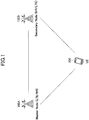
- Fig. 1 is a configuration example of a wireless communication system according to an embodiment of the present invention. Referring to Fig. 1 , an outline of a wireless communication system according to an embodiment of the present invention will be described.
- a user apparatus 200 (hereinafter referred to as a "UE 200") is connected to and communicates with a base station apparatus 100A and a base station apparatus 100B provided by the LTE system and the NR system, respectively (hereinafter, referred to as "base station apparatus 100" in the case of not distinguishing between the base station apparatus 100A and the base station apparatus 100B) .
- the user apparatus 200 supports LTE-NR dual connectivity in which the base station apparatus 100A is a master node and the base station apparatus 100B is a secondary node.
- the user apparatus 200 to perform simultaneous transmission to or simultaneous reception from the master base station apparatus 100A as a master node and the secondary base station apparatus 100B as a secondary node by simultaneously using a plurality of component carriers provided by the master base station apparatus 100A as a master node and the secondary base station apparatus 100B as a secondary node.
- a number of base station apparatuses 100 are typically arranged in the LTE system or the NR system to cover each service area.
- a user apparatus is not limited to be applicable to the LTE-NR dual connectivity, and may be applicable to dual connectivity between a plurality of wireless communication systems using different RATs, that is, the multi-RAT dual connectivity. Further, the user apparatus is also applicable to NR-NR dual connectivity using the same RAT.
- dual connectivity may be referred to as "DC".
- the duplex method may be TDD (Time Division Duplex), FDD (Frequency Division Duplex), or other methods (e.g., Flexible Duplex, or the like).
- transmitting a signal by using a transmission beam may be referred to as “transmitting a precoding-vector-multiplied signal (a signal precoded by a precoding vector)".
- receiving a signal by using a reception beam may be referred to as “multiplying the received signal by a predetermined weight vector.”
- transmitting a signal by using a transmission beam may be expressed as “transmitting a signal via a specific antenna port”.
- receiving a signal by using a reception beam may be expressed as “receiving a signal via a specific antenna port” .
- the antenna port refers to a logical antenna port or a physical antenna port defined in 3GPP standards. It should be noted that the method in which the transmission beam and the reception beam are formed are not limited to the methods described above. For example, a method may be used in which the base station apparatus 100 having plural antennas change each of the antenna angles and the user apparatus 200 having plural antennas change each of the antenna angles. A method in which the method of using precoding vectors and the method of changing antenna angles are combined may be used, or different antenna panels may be switched. The method of switching multiple antenna panels may be combined with other methods, or some other methods may be used. Further, for example, multiple transmission beams different from each other may be used in a high frequency band. An operation using multiple transmission beams is referred to as a "multi-beam operation", and an operation using a single transmission beam is referred to as a "single-beam operation”.
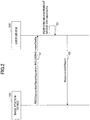
- Fig. 2 is an example of a sequence of a measurement procedure in an embodiment of the present invention.
- the base station apparatus 100 transmits "RRCConnectionReconfiguration" including an information element "measConfig" to the user apparatus 200 via an RRC message.
- the "measConfig” includes information related to a measurement configuration performed by the user apparatus 200. For example, information related to intra-frequency measurements, inter-frequency measurements, inter-RAT mobility measurements, measurement gap configuration, etc., may be included.
- RRCConnectionReconfiguration is an example.
- the "measConfig” may be indicated via another RRC message. For example, "measConfig" may be transmitted to the user apparatus 200 via "RRCConnectionResume".
- step S2 the user apparatus 200 performs measurements based on the configuration according to the measConfig received in step S1. Necessary measurements are performed on LTE cells or NR cells.
- step S3 the user apparatus 200 transmits the measurement results performed in step S2 to the base station apparatus 100 via an RRC message "MeasurementReport".
- the base station apparatus 100 performs the configuration of radio resources and scheduling required for the user apparatus 200 by referring to the received measurement results.
- an asynchronous DC is performed by an LTE node and an NR node.
- asynchronous DC it is not known how much the radio frame, slot or symbol timing difference between the LTE node and the NR node is.
- SFTD measurements are supported in which SFN and sub-frame timing between the master node (also referred to as "PCell") and the secondary node (also referred to as "PSCell") are measured and reported to the base station apparatus 100 by the user apparatus 200.
- PCell master node
- PSCell secondary node
- the user apparatus 200 measures an SFN offset, a frame boundary offset, and a sub-frame boundary offset between PCell and PSCell, and reports the measured offsets to the base station apparatus 100.
- MeasResultSSTD-r13 :: SEQUENCE ⁇ Sfn-OffsetResult-r13 INTEGER (0..1023), FrameBoundaryOffsetResult-r13 INTEGER (-5..4), SubframeBoundaryOffsetResult-r13 INTEGER (0..127) ⁇
- Sfn-OffsetResult is an information element that corresponds to the SFN offset and takes values from 0 to 1023.
- FrameBoundaryOffsetResult is an information element that corresponds to the frame boundary offset and takes values from -5 to 4.
- Subframe BoundaryOffsetResult is an information element that corresponds to the sub-frame boundary offset and takes values from 0 to 127.
- the base station apparatus 100 causes the user apparatus 200 to measure and report "MeasResultSSTD" after configuring the PSCell.
- PSCell is configured by the following procedure.
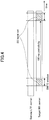
- Fig. 3 is a drawing illustrating an example (1) of a measurement procedure in an asynchronous DC according to an embodiment of the present invention. The operation of applying the procedure of the LTE-LTE asynchronous DC described in Fig. 2 to the LTE-NR asynchronous DC will be described.
- the Inter-frequency measurement with a measurement gap is configured to the user apparatus 200 by the master node of the LTE.
- the transmission period of the synchronous signal is 5 ms in LTE, so that the measurement can be performed in a window of 5 ms even when the master node and the secondary node are asynchronous.
- the synchronization signal SS Synchronization Signal
- the 5ms window contains at least one SS transmitted by SF #0 or SF #5.
- the Inter RAT NR measurement with a measurement gap is configured to the user apparatus 200 by the master node of the LTE.
- 5 ms, 10 ms, 20 ms, 40 ms, 80 ms, or 160 ms can be set as the transmission period of an SS block including a synchronization signal, so that a window of 160 ms is required to detect the synchronization signal when the master node and the secondary node are asynchronous .
- the window of 160 ms contains at least one SS burst set.
- the SS burst set includes one or more SS blocks.
- Fig. 4 is a drawing illustrating an example (2) of a measurement procedure in an asynchronous DC according to an embodiment of the present invention.
- the transmission period of the SS block can be set from 5 ms to 160 ms, in the case where the measurement target is an NR carrier and an NR PSCell is configured, the required measurement gap length in the inter-RAT measurement is increased.
- the SMTC (SS block measurement timing control) window can be set to be shorter than the SS burst transmission periodicity, by including the duration in which the SS burst set is transmitted.
- the user apparatus 200 cannot perform the SSTD measurement unless the PSCell is configured. Therefore, SS block measurement is required for SSTD measurement, and the required measurement gap length is increased.
- the measurement procedure there is a procedure that enables the SSTD measurement to be configured to the user apparatus 200 before the PSCell configuration.
- the SSTD measurement is configured to the user apparatus 200 before configuring the PSCell according to the information element "report-interRAT-SSTD-Meas".
- the user apparatus 200 measures the SSTD between the PCell and the detected inter-RAT cell.
- PCell acquires, in advance, information about an NR cell that may serve as a PSCell around the PCell, so that the parameters are indicated to the user apparatus 200.
- the information of 1) through 4) is semi-static information about the surrounding NR cells, and the measurement gap can be shortened when detecting the NR cells by acquiring the information at the user apparatus 200.
- an Inter-RAT SSTD measurement with a measurement gap may be configured to the user apparatus 200 by the master node.
- the measurement gap length for example, a value of ⁇ 5, 10, 20, 40, 80, 160 ⁇ ms plus 1 ms of returning time may be configured.
- the measurement gap period for example, ⁇ 40, 80 ⁇ ms may be configured, or other values may be configured.
- the measurement gap for the Inter-RAT SSTD measurement is configured separately from the measurement gap for the normal inter-frequency measurement or the inter-RAT measurement.
- the user apparatus 200 may prioritize (give higher priority to) the measurement gap for the Inter-RAT SSTD measurement, or may prioritize the measurement gap for the normal inter-frequency measurement or the inter-RAT measurement.
- an SCell deactivation timer may be stopped. The deactivation timer is stopped to prevent the SCell from being deactivated due to the measurement gap for the Inter-RAT STD measurement.
- the user apparatus 200 may measure the target frequency by operation equivalent to intra-frequency measurement. In other words, the user apparatus 200 has the ability to measure the target frequency without a measurement gap.
- the user apparatus 200 performs an SSTD measurement based on the configured timings of the PCell, e.g., the timing, period, or cycle of the SMTC.
- Inter-RAT SSTD measurement report may also contain the following information.
- the above-described SSTD measurement is performed before the PSCell is configured, but the above-described SSTD measurement may also be performed after the PSCell is configured.
- the timing difference between the PCell and the configured PSCell is measured and reported.
- Fig. 5 is a drawing illustrating an example (3) of a measurement procedure in an asynchronous DC according to an embodiment of the present invention. Referring to FIG. 5 , an example of configuring an SFTD measurement in a network in which an LTE carrier and an NR carrier are asynchronous will be described.
- the user apparatus 200 in which the SFTD measurement is configured, reports the timing difference information with the LTE PCell by searching for the NR cell and acquiring the SFN and frame timing of the detected NR cell in the specified frequency carrier.
- the SFTD measurement results for which NR cell should be reported to the base station apparatus 100 it was not clear under what conditions the SFTD measurement results for which NR cell should be reported to the base station apparatus 100.
- the conditions for reporting the SFTD measurement results are predefined or indicated to the user apparatus 200 by the base station apparatus 100.
- Such conditions relate to at least the maximum number of NR cells to be reported or the reception strength of the NR cells to be reported.
- the user apparatus 200 reports SFTD and PCI (Physical Cell Identifier) to the base station apparatus 100.
- SFTD Physical Cell Identifier
- PCI Physical Cell Identifier
- the SFTD measurement report is made because no higher NR cell was detected, even though the reception strength (RSRP) of the NR cell is low as an absolute value.
- RSRP reception strength
- the network configures the reported NR cell as PSCell for the user apparatus 200, the reception strength may be insufficient, and there is a possibility that sufficient throughput cannot be obtained even if EN-DC (E-UTRA-NR DC) is performed. In other words, the signaling, processing, or battery power required for the PSCell configuration is not effectively used.
- a candidate that can be configured as PSCell for the user apparatus 200 by the network is limited to only the reported NR cell.
- the following conditions related to SFTD measurements and reports are either predefined or indicated to the user apparatus 200 via signaling.
- the "target cell for SFTD measurement and reporting” may be the "target cell for SFTD measurement or reporting”.
- the number of cells reported for SFTD may be less than the number of cells measured for SFTD, or the number of cells measured for SFTD may be the same as the number of cells reported for SFTD.
- SFTD measurement and reporting are performed only for the cells whose RSRP exceeds the lower limit of the RSRP.
- the user apparatus 200 may report that, with respect to the cells whose RSRP is lower than the lower limit of the RSRP, RSRP of the cells is lower than the lower limit of the RSRP at the time of the SFTD report.
- only the cells detected as having an RSRP within a predetermined difference, compared to the cell with the highest RSRP among the cells detected by the user apparatus 200 may be included in the SFTD reporting.
- SFTD measurement is configured to (for) the user apparatus 200A or the user apparatus 200B by the base station apparatus 100A that is an LTE PCell.
- the base station apparatus 100A that is an LTE PCell.
- An example will be described in which the user apparatus 200A performs SFTD measurement on the base station apparatus 100B as an NR cell #0 and the base station apparatus 100D as an NR cell #2, based on the above-described conditions for SFTD measurement and reporting.
- the user apparatus 200A detects the base station apparatus 100B as an NR cell #0, the base station apparatus 100C as an NR cell #1, and the base station apparatus 100D as an NR cell #2, and it is assumed that, with respect to the reception strength, the user apparatus 200A detects that the NR cell #0 is -50dBm, the NR cell #1 is -80dBm, and the NR cell #2 is -65dBm.
- SFTD measurements and reporting are performed by the user apparatus 200 with respect to NR cell #0 and NR cell #2 .
- the number of target cells for SFTD measurement and reporting is defined or indicated as 3 cells from a higher reception strength, SFTD measurements and reporting are performed with respect to NR cell #0, NR cell #1, and NR cell #2.
- SFTD measurement and reporting are performed with respect to NR cell #0 and NR cell #2. Further, for example, in the case where the reception strength of the target cell for SFTD measurement and reporting is defined or indicated to be greater than -60 dBm, SFTD measurement and reporting are performed with respect to only NR cell #0.
- SFTD measurements and reporting are performed with respect to NR cell #0 and NR cell #2.
- SFTD measurement and reporting are performed with respect to only NR cell #0.
- the user apparatus 200 in the case where a plurality of NR cells are detected by the user apparatus 200 based on the SFTD measurement configuration that is predefined or indicated by the base station apparatus 100, it is possible for the user apparatus 200 to determine under what conditions the SFTD measurement is performed and reported to the base station apparatus 100.
- the user apparatus can perform measurements for dual connectivity performed in a wireless communication system using multiple RATs.
- the base station apparatus 100 and the user apparatus 200 each have at least functions for performing an embodiment of the present invention. It should be noted that the base station apparatus 100 and the user apparatus 200 each may have only a part of the functions for performing an embodiment of the present invention.
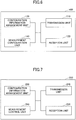
- Fig. 6 is a drawing illustrating an example of a functional structure of a base station apparatus 100.
- the base station apparatus 100 includes a transmission unit 110, a reception unit 120, a configuration information management unit 130, and a measurement configuration unit 140.
- the functional structure illustrated in Fig. 6 is merely an example. Functional divisions and names of functional units may be anything as long as it can perform operations according to an embodiment of the present invention.
- the transmission unit 110 has a function for generating a signal to be transmitted to the user apparatus 200 and for transmitting the signal wirelessly.
- the reception unit 120 has a function for receiving various signals transmitted from the user apparatus 200 and for obtaining, for example, upper layer information from the received signals. Further, the transmission unit 110 has a function for transmitting, to the user apparatus 200, NR-PSS, NR-SSS, NR-PBCH, DL/UL control signals, etc. Further, the transmission unit 110 transmits, to the user apparatus 200, information related to transmission power control, information related to scheduling, and information related to measurement configuration; and the reception unit 120 receives, from the user apparatus 200, a message related to a measurement result report.
- the configuration information management unit 130 stores preset configuration information and various configuration information items to be transmitted to the user apparatus 200. Contents of the configuration information are, for example, information related to measurement of the user apparatus 200, etc.
- the measurement configuring unit 140 performs: control pertaining to generation of information used for configuration of measurements performed by the user apparatus 200; and control pertaining to processing of measurement results received from the user apparatus 200.
- Fig. 7 is a drawing illustrating an example of a functional structure of a user apparatus 200.
- the user apparatus 200 includes a transmission unit 210, a reception unit 220, a configuration information management unit 230, and a measurement control unit 240.
- the functional structure illustrated in Fig. 7 is merely an example. Functional divisions and names of functional units may be anything as long as it can perform operations according to an embodiment of the present invention.
- the transmission unit 210 generates a transmission signal from transmission data and transmits the transmission signal wirelessly.
- the reception unit 220 receives various signals wirelessly and obtains upper layer signals from the received physical layer signals. Further, the reception unit 220 has a function for receiving NR-PSS, NR-SSS, NR-PBCH, DL/UL control signals, etc., transmitted from the base station apparatus 100. Further, the transmission unit 210 transmits, to the base station apparatus 100, a message related to a measurement result report, and the reception unit 220 receives, from the base station apparatus 100, information to be used for measurement configuration.
- the configuration information management unit 230 stores various configuration information items received by the reception unit 220 from the base station apparatus 100. Further, the configuration information management unit 230 also stores preset configuration information. Contents of the configuration information are, for example, information related to configuration for performing the measurements, etc.
- the measurement control unit 240 performs control pertaining to performing the measurement by the user apparatus 200 described in an embodiment of the present invention. It should be noted that the functional units related to measurement result transmission, etc., in the measurement control unit 240 may be included in the transmission unit 210, and the functional units related to configuration reception related to the measurement in the measurements control unit 240 may be included in the reception unit 220.
- each functional block is realized by a freely-selected combination of hardware and/or software. Further, realizing means of each functional block is not limited in particular. In other words, each functional block may be realized by a single apparatus in which multiple elements are coupled physically and/or logically, or may be realized by two or more apparatuses that are physically and/or logically separated and are physically and/or logically connected (e.g., wired and/or wireless).
- a base station apparatus 100 and a user apparatus 200 may function as computers that perform processes according to an embodiment of the present invention.
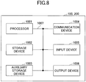
- Fig. 8 is a drawing illustrating an example of a hardware structure of a wireless communication apparatus that is a base station apparatus 100 or a user apparatus 200 according to an embodiment of the present invention.
- Each of the base station apparatus 100 and the user apparatus 200 may be physically a computer apparatus including a processor 1001, a storage device 1002, an auxiliary storage device 1003, a communication device 1004, an input device 1005, an output device 1006, a bus 1007, etc.
- the term "apparatus” can be read as a circuit, a device, a unit, etc.
- the hardware structures of the base station apparatus 100 and the user apparatus 200 may include one or more of each of the devices indicated by 1001 to 1006 illustrated in the figure, or may not include some apparatuses.
- Each of the functions of the base station apparatus 100 and the user apparatus 200 is realized by causing predetermined software (program) to be read by hardware such as the processor 1001, the storage device 1002, or the like, by causing the processor 1001 to perform calculations, and by causing the processor 1001 to control communications by the communication device 1004, and to control reading and/or writing data by the storage device 1002 and the auxiliary storage device 1003.
- predetermined software program
- the processor 1001 controls the entire computer by, for example, controlling the operating system.
- the processor 1001 may include a central processing unit (CPU) including an interface with a peripheral apparatus, a control apparatus, a calculation apparatus, a register, etc.
- CPU central processing unit
- the processor 1001 reads a program (program code), a software module, or data from the auxiliary storage device 1003 and/or the communication device 1004, writes the program, the software module, or the data to the storage device 1002, and performs various processes according to the program, the software module, or the data.
- a program is used that causes the computer to perform at least a part of operations according to an embodiment of the present invention described above.
- the transmission unit 110, the reception unit 120, the configuration information management unit 130, and the measurement control unit 140 of the base station apparatus 100 illustrated in Fig. 6 may be realized by control programs that are stored in the storage device 1002 and are executed by the processor 1001.
- the transmission unit 210, the reception unit 220, the configuration information management unit 230, and the measurements control unit 240 of the user apparatus 200 illustrated in Fig. 7 may be realized by control programs that are stored in the storage device 1002 and are executed by the processor 1001.
- the various processes have been described to be performed by a single processor 1001. However, the processes may be performed by two or more processors 1001 simultaneously or sequentially.
- the processor 1001 may be implemented by one or more chips. It should be noted that the program may be transmitted from a network via a telecommunication line.
- the storage device 1002 is a computer-readable recording medium, and may include at least one of a ROM (Read Only Memory), an EPROM (Erasable Programmable ROM), an EEPROM (Electrically Erasable Programmable ROM), a RAM (Random Access Memory), etc.
- the storage device 1002 may be referred to as a register, a cache, a main memory, etc.
- the storage device 1002 is enabled to store programs (program codes), software modules, or the like, that are executable for performing processes according to an embodiment of the present invention.
- the auxiliary storage device 1003 is a computer-readable recording medium, and may include at least one of, for example, an optical disk such as a CD-ROM (Compact Disc ROM), a hard disk drive, a flexible disk, a magneto optical disk (e.g., compact disk, digital versatile disk, Blu-ray (registered trademark) disk), a smart card, a flash memory (e.g., card, stick, key drive), a floppy (registered trademark) disk, a magnetic strip, etc.
- the above recording medium may be a database including the storage device 1002 and/or the auxiliary storage device 1003, a server, or any other appropriate medium.
- the communication device 1004 is hardware (transmission and reception device) for communicating with computers via a wired and/or wireless network, and may be referred to as a network device, a network controller, a network card, a communication module, etc.
- the transmission unit 110 and the reception unit 120 of the base station apparatus 100 may be realized by the communication device 1004.
- the transmission unit 210 and the reception unit 220 of the user apparatus 200 may be realized by the communication device 1004.
- the input device 1005 is an input device that receives an external input (e.g., keyboard, mouse, microphone, switch, button, sensor) .
- the output device 1006 is an output device that outputs something to the outside (e.g., display, speaker, LED lamp) . It should be noted that the input device 1005 and the output device 1006 may be integrated into a single device (e.g., touch panel).
- the apparatuses including the processor 1001, the storage device 1002, etc. are connected to each other via the bus 1007 used for communicating information.
- the bus 1007 may include a single bus, or may include different buses between the apparatuses.
- each of the base station apparatus 100 and the user apparatus 200 may include hardware such as a microprocessor, a digital signal processor (DSP), an ASIC (Application Specific Integrated Circuit), a PLD (Programmable Logic Device), a FPGA (Field Programmable Gate Array), etc., and a part or all of each functional block may be realized by the hardware.
- the processor 1001 may be implemented by at least one of the above hardware elements.
- a user apparatus for communicating with a first base station apparatus using a first RAT and a second base station apparatus using a second RAT different from the first RAT.
- the user apparatus includes a reception unit configured to receive, from the first base station apparatus, a configuration for measuring a timing difference between the first base station apparatus and the second base station apparatus; a control unit configured to perform measurement with respect to the second base station apparatus based on the configuration for measuring the timing difference; and a transmission unit configured to transmit, to the first base station apparatus, a result of the performed measurement, wherein the configuration for measuring the timing difference includes information indicating which of one or more of the second base stations is to be a measurement target.
- the user apparatus 200 determines an NR cell to be measured and to measure the SFTD among the detected NR cells based on the configuration for measuring the SFTD indicated by the base station apparatus 100. In other words, it is possible for the user apparatus to perform measurements for dual connectivity performed in a wireless communication system using multiple RATs.
- the information indicating which of the one or more of the second base station apparatuses is to be measured may include information indicating the number of the second base station apparatuses to be measured or information indicating an upper limit of the number of the second base station apparatuses to be measured. According to the above arrangement, it is possible for the user apparatus 200 to perform SFTD measurement on a desired number of NR cells and to perform reporting to the base station apparatus 100.
- the information indicating which of the one or more of the second base station apparatuses is to be measured may include information indicating that the detected second base station apparatuses are to be measured in order from the highest reception strength. According to the above arrangement, it is possible for the user apparatus 200 to perform SFTD measurement on a desired number of NR cells in order from the highest reception strength and to perform reporting to the base station apparatus 100.
- the information indicating which of the one or more of the second base station apparatuses is to be measured may include information indicating a lower limit of the reception strength of a signal transmitted from the second base station apparatus to be measured. According to the above arrangement, it is possible for the user apparatus 200 to perform SFTD measurement on NR cells that exceed a predetermined reception strength and to perform reporting to the base station apparatus 100.
- the information indicating which of the one or more of the second base station apparatuses is to be measured may include information indicating that the second base station apparatus having the highest reception strength among the detected second base station apparatuses and the second base station apparatus having a reception strength within a predetermined difference from the highest received strength are to be measured. According to the above arrangement, it is possible for the user apparatus 200 to perform SFTD measurement on NR cells that are within a predetermined reception strength from the highest detected reception strength and to perform reporting to the base station apparatus 100.
- the information indicating which of the one or more of the second base station apparatuses is to be measured may include information indicating to report, to the first base station apparatus, the detected second base station apparatus having a reception strength below the lower limit of the reception strength.
- the user apparatus 200 it is possible for the user apparatus 200 to report to the base station apparatus 100 that there exist NR cells below a predetermined reception strength. It is possible for the base station apparatus 100 to indicate, to the user apparatus 200, a configuration that reduces the reception strength of the target cell to perform the SFTD measurement based on the report.
- a user apparatus for communicating with a first base station apparatus using a first RAT (Radio Access Technology) and a second base station apparatus using a second RAT.
- the user apparatus includes a reception unit configured to receive, from the first base station apparatus, a configuration for measuring a timing difference between a cell of the first base station apparatus and a cell of the second base station apparatus; a control unit configured to perform measurement with respect to a cell of the second RAT based on the configuration for measuring the timing difference; and a transmission unit configured to transmit, to the first base station apparatus, a result of the performed measurement, wherein the configuration for measuring the timing difference includes information indicating an upper limit of a number of cells of the second RAT.
- the configuration for measuring the timing difference includes information indicating an upper limit of a number of cells of the second RAT.
- the user apparatus 200 determines an NR cell to be measured and to measure the SFTD among the detected NR cells based on the configuration for measuring the SFTD indicated by the base station apparatus 100. In other words, it is possible for the user apparatus to perform measurements for dual connectivity performed in a wireless communication system using multiple RATs.
- the configuration for measuring the timing difference may include information indicating a cell of the second RAT to be measured. According to the above arrangement, it is possible for the user apparatus 200 to perform SFTD measurement on a desired number of NR cells and to perform reporting to the base station apparatus 100.
- the measurement may be performed on up to a predetermined number of cells of the detected second RAT cells in order from the highest reception strength. According to the above arrangement, it is possible for the user apparatus 200 to perform SFTD measurement on NR cells in order from the highest reception strength and to perform reporting to the base station apparatus 100.
- the measurement may be performed on cells which exceed a lower limit of the reception strength of a signal transmitted from the detected second RAT cells. According to the above arrangement, it is possible for the user apparatus 200 to perform SFTD measurement on NR cells that exceed a predetermined reception strength and to perform reporting to the base station apparatus 100.
- Operations of multiple functional units may be physically performed by a single part, or an operation of a single functional unit may be physically performed by multiple parts.
- the order of sequences and flowcharts described in an embodiment of the present invention may be changed as long as there is no contradiction.
- a base station apparatus 100 and a user apparatus 200 have been described by using functional block diagrams.
- the apparatuses may be realized by hardware, software, or a combination of hardware and software.
- the software executed by a processor included in a base station apparatus 100 according to an embodiment of the present invention and the software executed by a processor included in a user apparatus 200 according to an embodiment of the present invention may be stored in a random access memory (RAM), a flash memory, a read only memory (ROM) , an EPROM, an EEPROM, a register, a hard disk (HDD), a removable disk, a CD-ROM, a database, a server, or any other appropriate recording medium.
- RAM random access memory
- ROM read only memory
- EPROM an EPROM
- EEPROM electrically erasable programmable read-only memory
- register a register
- HDD hard disk
- CD-ROM compact disc-read only memory
- database a database
- server or any other appropriate recording medium.
- information transmission may be performed not only by methods described in an aspect/embodiment of the present specification but also a method other than those described in an aspect/embodiment of the present specification.
- the information transmission may be performed by physical layer signaling (e.g., DCI (Downlink Control Information), UCI (Uplink Control Information)), upper layer signaling (e.g., RRC signaling, MAC signaling, broadcast information (MIB (Master Information Block), SIB (System Information Block))), other signals, or combinations thereof.
- RRC message may be referred to as RRC signaling.
- an RRC message may be, for example, an RRC connection setup message, an RRC connection reconfiguration message, or the like.
- An aspect/embodiment described in the present specification may be applied to a system that uses LTE (Long Term Evolution), LTE-A (LTE-Advanced), SUPER 3G, IMT-Advanced, 4G, 5G, FRA (Future Radio Access), W-CDMA (registered trademark), GSM (registered trademark), CDMA2000, UMB (Ultra Mobile Broadband), IEEE 802.11 (Wi-Fi), IEEE 802.16 (WiMAX), IEEE 802.20, UWB (Ultra-WideBand), Bluetooth (registered trademark), other appropriate systems, and/or a next generation system enhanced based thereon.
- LTE Long Term Evolution
- LTE-A LTE-Advanced
- SUPER 3G IMT-Advanced
- 4G 5G
- FRA Full Radio Access
- W-CDMA registered trademark
- GSM registered trademark
- CDMA2000 Code Division Multiple Access 2000
- UMB User Data Management Entity
- IEEE 802.11 Wi-Fi
- the particular operations, that are supposed to be performed by the base station apparatus 100 in the present specification, may be performed by an upper node in some cases.
- a network including one or more network nodes including a base station apparatus 100 it is apparent that various operations performed for communicating with a user apparatus 200 may be performed by the base station apparatus 100 and/or another network node other than the base station apparatus 100 (for example, but not limited to, MME or S-GW) .
- MME Mobility Management Entity
- An aspect/embodiment described in the present specification may be used independently, may be used in combination, or may be used by switching according to operations.
- the user apparatus 200 may be referred to, by a person skilled in the art, as a subscriber station, a mobile unit, a subscriber unit, a wireless unit, a remote unit, a mobile device, a wireless device, a wireless communication device, a remote device, a mobile subscriber station, an access terminal, a mobile terminal, a wireless terminal, a remote terminal, a handset, a user agent, a mobile client, a client, or some other appropriate terms.
- the base station apparatus 100 may be referred to, by a person skilled in the art, as a NB (NodeB), an eNB (enhanced NodeB), a gNB, a base station, or some other appropriate terms.
- NB NodeB
- eNB enhanced NodeB
- gNB gNodeB
- base station a base station, or some other appropriate terms.
- the term “determining” may encompasses a wide variety of actions.
- the “determining” may include, for example, a case in which "judging", “calculating”, “computing”, “processing”, “deriving”, “investigating”, “looking up” (e.g., looking up a table, database, or other data structures), or “ascertaining” is deemed as “determining”.
- “determining” may include a case in which “receiving” (e.g., receiving information), “transmitting” (e.g., transmitting information), “inputting", “outputting”, or “accessing” (e.g., accessing data in a memory) is deemed as “determining” .
- the "determining” may include a case in which “resolving”, “selecting”, “choosing”, “establishing”, “comparing”, or the like is deemed as “determining”. In other words, the “determining” may include a case in which a certain action or operation is deemed as “determining”.
- the measurement control unit 240 is an example of a control unit.
- the measurement configuration unit 140 is an example of a configuration unit.
Landscapes
- Engineering & Computer Science (AREA)
- Computer Networks & Wireless Communication (AREA)
- Signal Processing (AREA)
- Quality & Reliability (AREA)
- Physics & Mathematics (AREA)
- Electromagnetism (AREA)
- Mobile Radio Communication Systems (AREA)
Abstract
Description
- The present invention relates to a user apparatus in a wireless communication system.
- Currently, in 3GPP (Third Generation Partnership Project), specifications have been developed for a new wireless communication system that is called "NR (New Radio Access Technology) system" as a successor of "LTE (Long Term Evolution) system" and "LTE-Advanced system" (e.g., non-patent document 1).
- In the NR system, introduction of a technology called "LTE-NR Dual Connectivity" or "Multi-RAT (Multi Radio Access Technology) Dual Connectivity" has been discussed, in which, similar to the Dual Connectivity in the LTE system, data sets are divided between a base station of an LTE system (eNB) and a base station of an NR system (gNB) and the divided data sets are transmitted to or received by the base stations at the same time (e.g., non-patent document 2).
In addition, in the LTE-LTE dual connectivity, differences in the SFN (System Frame Number) and frame timing between the master node eNB and the secondary node eNB are measured by a user apparatus, and are reported to the network, which is referred to as SSTD (SFN and Subframe Timing Difference) or SFTD (SFN and Frame Timing Difference) (e.g., Non-Patent Document 3). -
- [Non-Patent Document 1] 3GPP TR38.804 V14.0.0 (2017-03)
- [Non-Patent Document 2] 3GPP TS37.340 V1.0.2 (2017-09)
- [Non-Patent Document 3] 3GPP TS36.331 V14.4.0 (2017-09)
- In LTE-NR dual connectivity, when performing asynchronous dual connectivity, the user apparatus needs to perform measurements on NR carriers of the gNB because it is not clear how much of the frame, slot, or symbol timing difference exists between the master node eNB and the secondary node gNB. However, the procedure for this measurement has not been established.
- The present invention has been made in view of the above, and is intended to enable a user apparatus to perform measurements for dual connectivity performed in a wireless communication system using a plurality of RATs.
- According to the disclosed technology, a user apparatus which communicates with a first base station apparatus using a first RAT (Radio Access Technology) and a second base station apparatus using a second RAT is provided. The user apparatus includes a reception unit configured to receive, from the first base station apparatus, a configuration for measuring a timing difference between a cell of the first base station apparatus and a cell of the second RAT,
a control unit configured to perform a measurement for the second RAT cell based on the configuration for measuring the timing difference, and a transmission unit configured to transmit a result of the performed measurement to the first base station apparatus, wherein the configuration for measuring the timing difference includes information indicating an upper limit of a number of cells of the second RAT. - According to the disclosed technology, it is possible for a user apparatus to perform measurements for dual connectivity performed in a wireless communication system using multiple RATs.
-
-
Fig. 1 is a drawing illustrating a configuration example of a wireless communication system according to an embodiment of the present invention. -
Fig. 2 is an example of a sequence of a measurement procedure in an embodiment of the present invention. -
Fig. 3 is a drawing illustrating an example (1) of a measurement procedure in an asynchronous DC according to an embodiment of the present invention. -
Fig. 4 is a drawing illustrating an example (2) of a measurement procedure in an asynchronous DC according to an embodiment of the present invention. -
Fig. 5 is a drawing illustrating an example (3) of a measurement procedure in an asynchronous DC according to an embodiment of the present invention. -
Fig. 6 is a drawing illustrating an example of a functional structure of abase station apparatus 100 according to an embodiment of the present invention. -
Fig. 7 is a drawing illustrating an example of a functional structure of auser apparatus 200 according to an embodiment of the present invention. -
Fig. 8 is a drawing illustrating examples of hardware structures of thebase station apparatus 100 and theuser apparatus 200. - In the following, referring to the drawings, one or more embodiments of the present invention will be described. It should be noted that the embodiments described below are examples. Embodiments of the present invention are not limited to the following embodiments.
- In operations of a wireless communication system according to an embodiment of the present invention, conventional techniques will be used appropriately. With respect to the above, for example, the conventional techniques are related to, but not limited to, the existing LTE. Further, it is assumed that the term "LTE" used in the present specification has, unless otherwise specifically mentioned, a broad meaning including a scheme of LTE-Advanced and a scheme after LTE-Advanced (e.g., NR).
- Further, in the following embodiments, the terms such as SS (Synchronization Signal), PSS (Primary SS), SSS (Secondary SS), PBCH (Physical broadcast channel), PRACH (Physical RACH), etc., are used for the sake of convenience. The signals, functions, etc., similar to the above, may be referred to by different terms. Further, the above-described terms used in NR will be referred to as "NR-SS", "NR-PSS", "NR-SSS", "NR-PBCH", "NR-PRACH", etc.
-
Fig. 1 is a configuration example of a wireless communication system according to an embodiment of the present invention.
Referring toFig. 1 , an outline of a wireless communication system according to an embodiment of the present invention will be described. - As illustrated in
Fig. 1 , a user apparatus 200 (hereinafter referred to as a "UE 200") is connected to and communicates with abase station apparatus 100A and abase station apparatus 100B provided by the LTE system and the NR system, respectively (hereinafter, referred to as "base station apparatus 100" in the case of not distinguishing between thebase station apparatus 100A and thebase station apparatus 100B) . Further, theuser apparatus 200 supports LTE-NR dual connectivity in which thebase station apparatus 100A is a master node and thebase station apparatus 100B is a secondary node.
In other words, it is possible for theuser apparatus 200 to perform simultaneous transmission to or simultaneous reception from the masterbase station apparatus 100A as a master node and the secondarybase station apparatus 100B as a secondary node by simultaneously using a plurality of component carriers provided by the masterbase station apparatus 100A as a master node and the secondarybase station apparatus 100B as a secondary node.
It should be noted that, although only one base station apparatus is illustrated for each of the LTE system and the NR system inFIG. 1 , a number ofbase station apparatuses 100 are typically arranged in the LTE system or the NR system to cover each service area. - It should be noted that embodiments below will be described with respect to the LTE-NR dual connectivity. A user apparatus according to an embodiment of the present invention is not limited to be applicable to the LTE-NR dual connectivity, and may be applicable to dual connectivity between a plurality of wireless communication systems using different RATs, that is, the multi-RAT dual connectivity. Further, the user apparatus is also applicable to NR-NR dual connectivity using the same RAT.
Hereinafter, dual connectivity may be referred to as "DC". - It should be noted that, in an embodiment of the present invention, the duplex method may be TDD (Time Division Duplex), FDD (Frequency Division Duplex), or other methods (e.g., Flexible Duplex, or the like).
- Further, in the following descriptions, "transmitting a signal by using a transmission beam" may be referred to as "transmitting a precoding-vector-multiplied signal (a signal precoded by a precoding vector)". Similarly, "receiving a signal by using a reception beam" may be referred to as "multiplying the received signal by a predetermined weight vector." Further, "transmitting a signal by using a transmission beam" may be expressed as "transmitting a signal via a specific antenna port". Similarly, "receiving a signal by using a reception beam" may be expressed as "receiving a signal via a specific antenna port" . The antenna port refers to a logical antenna port or a physical antenna port defined in 3GPP standards. It should be noted that the method in which the transmission beam and the reception beam are formed are not limited to the methods described above. For example, a method may be used in which the
base station apparatus 100 having plural antennas change each of the antenna angles and theuser apparatus 200 having plural antennas change each of the antenna angles. A method in which the method of using precoding vectors and the method of changing antenna angles are combined may be used, or different antenna panels may be switched. The method of switching multiple antenna panels may be combined with other methods, or some other methods may be used. Further, for example, multiple transmission beams different from each other may be used in a high frequency band. An operation using multiple transmission beams is referred to as a "multi-beam operation", and an operation using a single transmission beam is referred to as a "single-beam operation". - In the following, one or more embodiments will be described.
-
Fig. 2 is an example of a sequence of a measurement procedure in an embodiment of the present invention. In step S1, thebase station apparatus 100 transmits "RRCConnectionReconfiguration" including an information element "measConfig" to theuser apparatus 200 via an RRC message. The "measConfig" includes information related to a measurement configuration performed by theuser apparatus 200. For example, information related to intra-frequency measurements, inter-frequency measurements, inter-RAT mobility measurements, measurement gap configuration, etc., may be included. It should be noted that "RRCConnectionReconfiguration" is an example. The "measConfig" may be indicated via another RRC message. For example, "measConfig" may be transmitted to theuser apparatus 200 via "RRCConnectionResume". - In step S2, the
user apparatus 200 performs measurements based on the configuration according to the measConfig received in step S1. Necessary measurements are performed on LTE cells or NR cells. - In step S3, the
user apparatus 200 transmits the measurement results performed in step S2 to thebase station apparatus 100 via an RRC message "MeasurementReport". Thebase station apparatus 100 performs the configuration of radio resources and scheduling required for theuser apparatus 200 by referring to the received measurement results. - Here, it is assumed that an asynchronous DC is performed by an LTE node and an NR node. In the asynchronous DC, it is not known how much the radio frame, slot or symbol timing difference between the LTE node and the NR node is. In the LTE-LTE DC, SFTD measurements are supported in which SFN and sub-frame timing between the master node (also referred to as "PCell") and the secondary node (also referred to as "PSCell") are measured and reported to the
base station apparatus 100 by theuser apparatus 200. By performing the SFTD measurements, for example, the active period of DRX (Discontinuous reception) can be synchronized between the master node and the secondary node. - In the SSTD measurements of the LTE, the
user apparatus 200 measures an SFN offset, a frame boundary offset, and a sub-frame boundary offset between PCell and PSCell, and reports the measured offsets to thebase station apparatus 100. The following is an example of the RRC message "MeasResultSFTD" regarding the configuration of the SFTD measurements for theuser apparatus 200.
MeasResultSSTD-r13 ::= SEQUENCE { Sfn-OffsetResult-r13 INTEGER (0..1023), FrameBoundaryOffsetResult-r13 INTEGER (-5..4), SubframeBoundaryOffsetResult-r13 INTEGER (0..127) } - Sfn-OffsetResult is an information element that corresponds to the SFN offset and takes values from 0 to 1023. FrameBoundaryOffsetResult is an information element that corresponds to the frame boundary offset and takes values from -5 to 4. Subframe BoundaryOffsetResult is an information element that corresponds to the sub-frame boundary offset and takes values from 0 to 127. The
base station apparatus 100 causes theuser apparatus 200 to measure and report "MeasResultSSTD" after configuring the PSCell. - With respect to the above, in order for the
user apparatus 200 to configure PSCell, it is necessary to perform cell detection and report to thebase station apparatus 100. In an asynchronous DC in LTE, PSCell is configured by the following procedure. - 1) Inter-frequency measurement with a measurement gap is configured to the
user apparatus 200 by the master node. - 2) The master node recognizes a PSCell ID from the measurement report results and configures PSCell to the
user apparatus 200. - 3) The master node configures SSTD measurements for the
user apparatus 200. - 4) The master node recognizes a timing offset between the master node and the secondary node based on the SSTD measurement result report from the
user apparatus 200 and shares the timing offset with the secondary node. -
Fig. 3 is a drawing illustrating an example (1) of a measurement procedure in an asynchronous DC according to an embodiment of the present invention. The operation of applying the procedure of the LTE-LTE asynchronous DC described inFig. 2 to the LTE-NR asynchronous DC will be described. - In the case where the measurement target is an LTE carrier used for performing the asynchronous DC, the Inter-frequency measurement with a measurement gap is configured to the
user apparatus 200 by the master node of the LTE. As illustrated in the upper figure ofFIG. 3 , the transmission period of the synchronous signal is 5 ms in LTE, so that the measurement can be performed in a window of 5 ms even when the master node and the secondary node are asynchronous. In the upper figure ofFIG. 3 , the synchronization signal SS (Synchronization Signal) is detected at SF (sub-frame) #0 andSF # 5. That is, the 5ms window contains at least one SS transmitted bySF # 0 orSF # 5. - On the other hand, in the case where the measurement target is an NR carrier used for performing asynchronous DC, the Inter RAT NR measurement with a measurement gap is configured to the
user apparatus 200 by the master node of the LTE. As illustrated in the lower figure ofFIG. 3 , in NR, 5 ms, 10 ms, 20 ms, 40 ms, 80 ms, or 160 ms can be set as the transmission period of an SS block including a synchronization signal, so that a window of 160 ms is required to detect the synchronization signal when the master node and the secondary node are asynchronous . That is, the window of 160 ms contains at least one SS burst set. It should be noted that the SS burst set includes one or more SS blocks. -
Fig. 4 is a drawing illustrating an example (2) of a measurement procedure in an asynchronous DC according to an embodiment of the present invention. As described inFIG. 3 , in the NR, because the transmission period of the SS block can be set from 5 ms to 160 ms, in the case where the measurement target is an NR carrier and an NR PSCell is configured, the required measurement gap length in the inter-RAT measurement is increased. - Here, if the timing difference between the master node and the secondary node is obtained by the network in advance by the SSTD measurement, it is possible to configure an appropriate measurement timing to the
user apparatus 200. As illustrated inFIG. 4 , the SMTC (SS block measurement timing control) window can be set to be shorter than the SS burst transmission periodicity, by including the duration in which the SS burst set is transmitted. However, theuser apparatus 200 cannot perform the SSTD measurement unless the PSCell is configured. Therefore, SS block measurement is required for SSTD measurement, and the required measurement gap length is increased. - Accordingly, in order to efficiently execute the LTE-NR asynchronous DC, for example, it is necessary to perform a measurement procedure that does not have a mechanism for measuring the timing difference on the network side and avoids the communication unavailable state in the serving cell due to the increased measurement gap length.
- As the measurement procedure, there is a procedure that enables the SSTD measurement to be configured to the
user apparatus 200 before the PSCell configuration. For example, the SSTD measurement is configured to theuser apparatus 200 before configuring the PSCell according to the information element "report-interRAT-SSTD-Meas". According to the information element "report-interRAT-SSTD-Meas", theuser apparatus 200 measures the SSTD between the PCell and the detected inter-RAT cell. Some or all of the following parameters can be configured from the Measurement object, etc. - 1) Measurement target frequency and SS Block frequency position
- 2) SS burst set periodicity
- 3) SMTC cycle and period, and one of {5, 10, 20, 40, 80, 160} ms as the SMTC window period
- 4) SS block sub-carrier spacing
- 5) Number of cells reported
- 6) Reporting period and number of reporting times, etc.
- 7) Reporting contents
- With respect to information of 1) the measurement target frequency and SS Block frequency position, 2) SS burst set periodicity, 3) SMTC cycle and period, and one of {5, 10, 20, 40, 80, 160} ms as the SMTC window period, and 4) SS block sub-carrier spacing, PCell acquires, in advance, information about an NR cell that may serve as a PSCell around the PCell, so that the parameters are indicated to the
user apparatus 200. The information of 1) through 4) is semi-static information about the surrounding NR cells, and the measurement gap can be shortened when detecting the NR cells by acquiring the information at theuser apparatus 200. -
- 5) With respect to the number of cells reported, in the case where multiple cells are configured, multiple cell IDs and the SSTD measurement result for each cell may be reported.
- 6) With respect to the reporting period and the number of reporting times, etc., a periodic report may be configured or the number of reporting times may be configured. For example, the
user apparatus 200 may perform reporting even if the NR cell is not detected at the target frequency, and may stop the measurement report after a predetermined number of times has been reached or a predetermined time has elapsed, or theuser apparatus 200 may stop the measurement report after a predetermined time has elapsed without reporting. - 7) With respect to the reporting contents, in addition to the SSTD measurement results, some or all of the detected cell's RSRP (Reference Signal Received Power), RSRQ (Reference Signal Received Quality), SINR (Signal-to-Interference plus Noise power Ratio), beam ID, or RSRP may be configured to be reported.
- In addition, based on the information of the SS burst set periodicity applied to the secondary node, an Inter-RAT SSTD measurement with a measurement gap may be configured to the
user apparatus 200 by the master node. With respect to the measurement gap length, for example, a value of {5, 10, 20, 40, 80, 160} ms plus 1 ms of returning time may be configured. With respect to the measurement gap period, for example, {40, 80} ms may be configured, or other values may be configured. - In serving cells in which a measurement gap for the Inter-RAT SSTD measurement is configured, it is not necessary for reception of PDSCH or PDCCH and transmission of PUCCH or PUSCH, etc., within the measurement gap to be performed.
- The measurement gap for the Inter-RAT SSTD measurement is configured separately from the measurement gap for the normal inter-frequency measurement or the inter-RAT measurement. In the case where multiple measurement gaps overlap, the
user apparatus 200 may prioritize (give higher priority to) the measurement gap for the Inter-RAT SSTD measurement, or may prioritize the measurement gap for the normal inter-frequency measurement or the inter-RAT measurement. - In the case where a measurement gap for the Inter-RAT SSTD measurement is configured for PCell belonging to the master node and carrier-aggregated SCell, an SCell deactivation timer may be stopped. The deactivation timer is stopped to prevent the SCell from being deactivated due to the measurement gap for the Inter-RAT STD measurement.
- Further, in the case where the Inter-RAT SSTD measurement is configured by the master node, the
user apparatus 200 may measure the target frequency by operation equivalent to intra-frequency measurement. In other words, theuser apparatus 200 has the ability to measure the target frequency without a measurement gap. Theuser apparatus 200 performs an SSTD measurement based on the configured timings of the PCell, e.g., the timing, period, or cycle of the SMTC. - It should be noted that it may be assumed that an interruption occurs temporarily in the serving cell at the time when the Inter-RAT SSTD measurement is configured, that is, the start time of the SMTC window. Interruption occurs in the
user apparatus 200, for example, due to the switching time of the RF module. However, SSTD measurements of surrounding NR cells can be made without configuring a large measurement gap. - Here, it may be assumed that no further interruption occurs in the case where PSCell is configured to the
user apparatus 200 based on the SSTD measurement result report. This is because the report obtained in SSTD measurements can be used to configure PSCell. - Further, the Inter-RAT SSTD measurement report may also contain the following information.
- 1) Detected cell ID
- 2) SFN offset
- 3) Frame boundary offset
- 4) Slot boundary offset
- 5) Measurement result related to electric power
- 6) Beam ID
-
- 1) With respect to the detected cell ID, the
user apparatus 200 may report a plurality of cell IDs up to the configured number of reporting cells. - 2) With respect to the SFN offset, the
user apparatus 200 may report the SFN offset for each cell. - 3) With respect to the frame boundary offset, the
user apparatus 200 may report the frame boundary offset for each cell. The bit width indicating the offset information may be changed according to the sub-carrier spacing of the configured SS Block. For example, theuser apparatus 200 reports a slot index in the NR cell that matches the timing of the boundary of thePCell sub-frame # 0. - 4) With respect to the slot boundary offset, the
user apparatus 200 may report the slot boundary offset for each cell. The bit width indicating the offset information may be changed according to the sub-carrier spacing of the configured SS Block. For example, theuser apparatus 200 reports an index of symbol units in the NR cell that matches the timing of the PCell sub-frame boundary. - 5) With respect to the measurement result related to electric power, the measurement result may be, for example, RSRP, RSRQ, and SINR, and reported on a cell-by-cell basis. RSRP, RSRQ, and SINR may be reported for each beam in the case where the report of the beam measurement results is configured to (at) the
user apparatus 200. - 6) With respect to the beam ID, the beam ID is reported in the case where a beam measurement result report is configured to (in) the
user apparatus 200. - The above-described SSTD measurement is performed before the PSCell is configured, but the above-described SSTD measurement may also be performed after the PSCell is configured. In the SSTD measurement, the timing difference between the PCell and the configured PSCell is measured and reported.
-
Fig. 5 is a drawing illustrating an example (3) of a measurement procedure in an asynchronous DC according to an embodiment of the present invention. Referring toFIG. 5 , an example of configuring an SFTD measurement in a network in which an LTE carrier and an NR carrier are asynchronous will be described. - The
user apparatus 200, in which the SFTD measurement is configured, reports the timing difference information with the LTE PCell by searching for the NR cell and acquiring the SFN and frame timing of the detected NR cell in the specified frequency carrier. However, it was not clear under what conditions the SFTD measurement results for which NR cell should be reported to thebase station apparatus 100. - Accordingly, the conditions for reporting the SFTD measurement results (e.g., SFTD with respect to which cell should be reported in a case where a plurality of NR cells are detected) are predefined or indicated to the
user apparatus 200 by thebase station apparatus 100. Such conditions relate to at least the maximum number of NR cells to be reported or the reception strength of the NR cells to be reported. - Here, for example, with respect to the NR cell with the highest reception strength, a case will be discussed in which the
user apparatus 200 reports SFTD and PCI (Physical Cell Identifier) to thebase station apparatus 100. In the case where an SFTD measurement report is performed only for a single NR cell with the highest reception strength, there may be a case in which the SFTD measurement report is made because no higher NR cell was detected, even though the reception strength (RSRP) of the NR cell is low as an absolute value. In this case, if the network configures the reported NR cell as PSCell for theuser apparatus 200, the reception strength may be insufficient, and there is a possibility that sufficient throughput cannot be obtained even if EN-DC (E-UTRA-NR DC) is performed. In other words, the signaling, processing, or battery power required for the PSCell configuration is not effectively used. - Also, for example, in the case where the SFTD measurement report is performed only for a single NR cell with the highest reception strength in spite of the fact that a plurality of NR cells whose reception strength is sufficiently high are detected, a candidate that can be configured as PSCell for the
user apparatus 200 by the network is limited to only the reported NR cell. For example, it may be desirable to report a plurality of NR cells that are PSCell candidates with sufficient reception strength in case of assuming a situation in which the reported NR cell is congested with manyother user apparatuses 200 and other detected NR cells are not congested at all. - Accordingly, the following conditions related to SFTD measurements and reports are either predefined or indicated to the
user apparatus 200 via signaling. It should be noted that the "target cell for SFTD measurement and reporting" may be the "target cell for SFTD measurement or reporting". For example, the number of cells reported for SFTD may be less than the number of cells measured for SFTD, or the number of cells measured for SFTD may be the same as the number of cells reported for SFTD. - 1) Number of cells for which SFTD measurement and reporting are performed
For example, in the case where the number of cells for which SFTD measurement and reporting are performed is defined or indicated as "2 cells", theuser apparatus 200 may perform SFTD measurement and reporting on at least 2 cells detected by theuser apparatus 200. Further, theuser apparatus 200 may select two cells from the cells detected by theuser apparatus 200 in the descending order of high reception strength to perform SFTD measurements and reports. - 2) Upper limit of the number of cells for which SFTD measurement and reporting are performed
For example, in the case where the number of cells detected by theuser apparatus 200 is less than the upper limit, SFTD measurements and reporting are performed for all detected cells.
In the case where the number of cells detected by theuser apparatus 200 is greater than the upper limit, SFTD measurements and reporting are performed for the highest reception strength cells among the detected cells which are equal in number to the upper limit. - 3) Lower limit of the reception strength (RSRP) of the target cells for which SFTD measurement and reporting are performed
- For example, of all the cells detected by the
user apparatus 200, SFTD measurement and reporting are performed only for the cells whose RSRP exceeds the lower limit of the RSRP. Alternatively, theuser apparatus 200 may report that, with respect to the cells whose RSRP is lower than the lower limit of the RSRP, RSRP of the cells is lower than the lower limit of the RSRP at the time of the SFTD report. Alternatively, only the cells detected as having an RSRP within a predetermined difference, compared to the cell with the highest RSRP among the cells detected by theuser apparatus 200, may be included in the SFTD reporting. - It should be noted that combined conditions described in 1), 2) and 3) above may be defined or indicated to the
user apparatus 200 as conditions for SFTD measurement and reporting. - As illustrated in
FIG. 5 , SFTD measurement is configured to (for) theuser apparatus 200A or theuser apparatus 200B by thebase station apparatus 100A that is an LTE PCell. An example will be described in which theuser apparatus 200A performs SFTD measurement on thebase station apparatus 100B as anNR cell # 0 and thebase station apparatus 100D as anNR cell # 2, based on the above-described conditions for SFTD measurement and reporting. It should be noted that it is assumed that theuser apparatus 200A detects thebase station apparatus 100B as anNR cell # 0, thebase station apparatus 100C as anNR cell # 1, and thebase station apparatus 100D as anNR cell # 2, and it is assumed that, with respect to the reception strength, theuser apparatus 200A detects that theNR cell # 0 is -50dBm, theNR cell # 1 is -80dBm, and theNR cell # 2 is -65dBm. - For example, in the case where the number of target cells for SFTD measurement and reporting is defined or indicated as 2 cells with higher reception strength, because
NR cell # 0 andNR cell # 2 are two cells with stronger reception strength, SFTD measurements and reporting are performed by theuser apparatus 200 with respect toNR cell # 0 andNR cell # 2 . Further, for example, in the case where the number of target cells for SFTD measurement and reporting is defined or indicated as 3 cells from a higher reception strength, SFTD measurements and reporting are performed with respect toNR cell # 0,NR cell # 1, andNR cell # 2. - For example, in the case where the reception strength of the target cells for SFTD measurement and reporting is defined or indicated to be greater than -75 dBm, SFTD measurement and reporting are performed with respect to
NR cell # 0 andNR cell # 2. Further, for example, in the case where the reception strength of the target cell for SFTD measurement and reporting is defined or indicated to be greater than -60 dBm, SFTD measurement and reporting are performed with respect to onlyNR cell # 0. - For example, in the case where the target cell for SFTD measurement and reporting is defined or indicated as a cell within 20 dB of the highest reception strength of the detected cells, SFTD measurements and reporting are performed with respect to
NR cell # 0 andNR cell # 2. Further, for example, in the case where the target cell for SFTD measurement and reporting is defined or indicated as a cell within 10 dB of the highest reception strength of the detected cells, SFTD measurement and reporting are performed with respect to onlyNR cell # 0. - In the above-described embodiment, in the case where a plurality of NR cells are detected by the
user apparatus 200 based on the SFTD measurement configuration that is predefined or indicated by thebase station apparatus 100, it is possible for theuser apparatus 200 to determine under what conditions the SFTD measurement is performed and reported to thebase station apparatus 100. - In other words, it is possible for the user apparatus to perform measurements for dual connectivity performed in a wireless communication system using multiple RATs.
- Next, examples of functional structures of the
base station apparatus 100 and theuser apparatus 200 that perform the processes and operations described above will be described. Thebase station apparatus 100 and theuser apparatus 200 each have at least functions for performing an embodiment of the present invention. It should be noted that thebase station apparatus 100 and theuser apparatus 200 each may have only a part of the functions for performing an embodiment of the present invention. -
Fig. 6 is a drawing illustrating an example of a functional structure of abase station apparatus 100. As illustrated inFig. 6 , thebase station apparatus 100 includes atransmission unit 110, areception unit 120, a configurationinformation management unit 130, and ameasurement configuration unit 140. The functional structure illustrated inFig. 6 is merely an example. Functional divisions and names of functional units may be anything as long as it can perform operations according to an embodiment of the present invention. - The
transmission unit 110 has a function for generating a signal to be transmitted to theuser apparatus 200 and for transmitting the signal wirelessly. Thereception unit 120 has a function for receiving various signals transmitted from theuser apparatus 200 and for obtaining, for example, upper layer information from the received signals. Further, thetransmission unit 110 has a function for transmitting, to theuser apparatus 200, NR-PSS, NR-SSS, NR-PBCH, DL/UL control signals, etc. Further, thetransmission unit 110 transmits, to theuser apparatus 200, information related to transmission power control, information related to scheduling, and information related to measurement configuration; and thereception unit 120 receives, from theuser apparatus 200, a message related to a measurement result report. - The configuration
information management unit 130 stores preset configuration information and various configuration information items to be transmitted to theuser apparatus 200. Contents of the configuration information are, for example, information related to measurement of theuser apparatus 200, etc. - The
measurement configuring unit 140 performs: control pertaining to generation of information used for configuration of measurements performed by theuser apparatus 200; and control pertaining to processing of measurement results received from theuser apparatus 200. -
Fig. 7 is a drawing illustrating an example of a functional structure of auser apparatus 200. As illustrated inFig. 7 , theuser apparatus 200 includes atransmission unit 210, areception unit 220, a configurationinformation management unit 230, and ameasurement control unit 240. The functional structure illustrated inFig. 7 is merely an example. Functional divisions and names of functional units may be anything as long as it can perform operations according to an embodiment of the present invention. - The
transmission unit 210 generates a transmission signal from transmission data and transmits the transmission signal wirelessly. Thereception unit 220 receives various signals wirelessly and obtains upper layer signals from the received physical layer signals. Further, thereception unit 220 has a function for receiving NR-PSS, NR-SSS, NR-PBCH, DL/UL control signals, etc., transmitted from thebase station apparatus 100. Further, thetransmission unit 210 transmits, to thebase station apparatus 100, a message related to a measurement result report, and thereception unit 220 receives, from thebase station apparatus 100, information to be used for measurement configuration. - The configuration
information management unit 230 stores various configuration information items received by thereception unit 220 from thebase station apparatus 100. Further, the configurationinformation management unit 230 also stores preset configuration information. Contents of the configuration information are, for example, information related to configuration for performing the measurements, etc. - The
measurement control unit 240 performs control pertaining to performing the measurement by theuser apparatus 200 described in an embodiment of the present invention. It should be noted that the functional units related to measurement result transmission, etc., in themeasurement control unit 240 may be included in thetransmission unit 210, and the functional units related to configuration reception related to the measurement in themeasurements control unit 240 may be included in thereception unit 220. - In the above functional structure diagrams used for describing an embodiment of the present invention (
Fig. 6 and Fig. 7 ), functional unit blocks are shown. The functional blocks (function units) are realized by a freely-selected combination of hardware and/or software. Further, realizing means of each functional block is not limited in particular. In other words, each functional block may be realized by a single apparatus in which multiple elements are coupled physically and/or logically, or may be realized by two or more apparatuses that are physically and/or logically separated and are physically and/or logically connected (e.g., wired and/or wireless). - Further, for example, a
base station apparatus 100 and auser apparatus 200 according to an embodiment of the present invention may function as computers that perform processes according to an embodiment of the present invention.Fig. 8 is a drawing illustrating an example of a hardware structure of a wireless communication apparatus that is abase station apparatus 100 or auser apparatus 200 according to an embodiment of the present invention. Each of thebase station apparatus 100 and theuser apparatus 200 may be physically a computer apparatus including aprocessor 1001, astorage device 1002, anauxiliary storage device 1003, acommunication device 1004, aninput device 1005, anoutput device 1006, abus 1007, etc. - It should be noted that, in the descriptions below, the term "apparatus" can be read as a circuit, a device, a unit, etc. The hardware structures of the
base station apparatus 100 and theuser apparatus 200 may include one or more of each of the devices indicated by 1001 to 1006 illustrated in the figure, or may not include some apparatuses. - Each of the functions of the
base station apparatus 100 and theuser apparatus 200 is realized by causing predetermined software (program) to be read by hardware such as theprocessor 1001, thestorage device 1002, or the like, by causing theprocessor 1001 to perform calculations, and by causing theprocessor 1001 to control communications by thecommunication device 1004, and to control reading and/or writing data by thestorage device 1002 and theauxiliary storage device 1003. - The
processor 1001 controls the entire computer by, for example, controlling the operating system. Theprocessor 1001 may include a central processing unit (CPU) including an interface with a peripheral apparatus, a control apparatus, a calculation apparatus, a register, etc. - Further, the
processor 1001 reads a program (program code), a software module, or data from theauxiliary storage device 1003 and/or thecommunication device 1004, writes the program, the software module, or the data to thestorage device 1002, and performs various processes according to the program, the software module, or the data. As the program, a program is used that causes the computer to perform at least a part of operations according to an embodiment of the present invention described above. For example, thetransmission unit 110, thereception unit 120, the configurationinformation management unit 130, and themeasurement control unit 140 of thebase station apparatus 100 illustrated inFig. 6 may be realized by control programs that are stored in thestorage device 1002 and are executed by theprocessor 1001. Further, for example, thetransmission unit 210, thereception unit 220, the configurationinformation management unit 230, and themeasurements control unit 240 of theuser apparatus 200 illustrated inFig. 7 may be realized by control programs that are stored in thestorage device 1002 and are executed by theprocessor 1001. The various processes have been described to be performed by asingle processor 1001. However, the processes may be performed by two ormore processors 1001 simultaneously or sequentially. Theprocessor 1001 may be implemented by one or more chips. It should be noted that the program may be transmitted from a network via a telecommunication line. - The
storage device 1002 is a computer-readable recording medium, and may include at least one of a ROM (Read Only Memory), an EPROM (Erasable Programmable ROM), an EEPROM (Electrically Erasable Programmable ROM), a RAM (Random Access Memory), etc. Thestorage device 1002 may be referred to as a register, a cache, a main memory, etc. Thestorage device 1002 is enabled to store programs (program codes), software modules, or the like, that are executable for performing processes according to an embodiment of the present invention. - The
auxiliary storage device 1003 is a computer-readable recording medium, and may include at least one of, for example, an optical disk such as a CD-ROM (Compact Disc ROM), a hard disk drive, a flexible disk, a magneto optical disk (e.g., compact disk, digital versatile disk, Blu-ray (registered trademark) disk), a smart card, a flash memory (e.g., card, stick, key drive), a floppy (registered trademark) disk, a magnetic strip, etc. The above recording medium may be a database including thestorage device 1002 and/or theauxiliary storage device 1003, a server, or any other appropriate medium. - The
communication device 1004 is hardware (transmission and reception device) for communicating with computers via a wired and/or wireless network, and may be referred to as a network device, a network controller, a network card, a communication module, etc. For example, thetransmission unit 110 and thereception unit 120 of thebase station apparatus 100 may be realized by thecommunication device 1004. Further, thetransmission unit 210 and thereception unit 220 of theuser apparatus 200 may be realized by thecommunication device 1004. - The
input device 1005 is an input device that receives an external input (e.g., keyboard, mouse, microphone, switch, button, sensor) . Theoutput device 1006 is an output device that outputs something to the outside (e.g., display, speaker, LED lamp) . It should be noted that theinput device 1005 and theoutput device 1006 may be integrated into a single device (e.g., touch panel). - Further, the apparatuses including the
processor 1001, thestorage device 1002, etc., are connected to each other via thebus 1007 used for communicating information. Thebus 1007 may include a single bus, or may include different buses between the apparatuses. - Further, each of the
base station apparatus 100 and theuser apparatus 200 may include hardware such as a microprocessor, a digital signal processor (DSP), an ASIC (Application Specific Integrated Circuit), a PLD (Programmable Logic Device), a FPGA (Field Programmable Gate Array), etc., and a part or all of each functional block may be realized by the hardware. For example, theprocessor 1001 may be implemented by at least one of the above hardware elements. - As described above, according to an embodiment of the present invention, a user apparatus for communicating with a first base station apparatus using a first RAT and a second base station apparatus using a second RAT different from the first RAT is provided. The user apparatus includes a reception unit configured to receive, from the first base station apparatus, a configuration for measuring a timing difference between the first base station apparatus and the second base station apparatus; a control unit configured to perform measurement with respect to the second base station apparatus based on the configuration for measuring the timing difference; and a transmission unit configured to transmit, to the first base station apparatus, a result of the performed measurement, wherein the configuration for measuring the timing difference includes information indicating which of one or more of the second base stations is to be a measurement target.
- According to the above arrangement, it is possible for the
user apparatus 200 to determine an NR cell to be measured and to measure the SFTD among the detected NR cells based on the configuration for measuring the SFTD indicated by thebase station apparatus 100. In other words, it is possible for the user apparatus to perform measurements for dual connectivity performed in a wireless communication system using multiple RATs. - The information indicating which of the one or more of the second base station apparatuses is to be measured may include information indicating the number of the second base station apparatuses to be measured or information indicating an upper limit of the number of the second base station apparatuses to be measured. According to the above arrangement, it is possible for the
user apparatus 200 to perform SFTD measurement on a desired number of NR cells and to perform reporting to thebase station apparatus 100. - The information indicating which of the one or more of the second base station apparatuses is to be measured may include information indicating that the detected second base station apparatuses are to be measured in order from the highest reception strength. According to the above arrangement, it is possible for the
user apparatus 200 to perform SFTD measurement on a desired number of NR cells in order from the highest reception strength and to perform reporting to thebase station apparatus 100. - The information indicating which of the one or more of the second base station apparatuses is to be measured may include information indicating a lower limit of the reception strength of a signal transmitted from the second base station apparatus to be measured. According to the above arrangement, it is possible for the
user apparatus 200 to perform SFTD measurement on NR cells that exceed a predetermined reception strength and to perform reporting to thebase station apparatus 100. - The information indicating which of the one or more of the second base station apparatuses is to be measured may include information indicating that the second base station apparatus having the highest reception strength among the detected second base station apparatuses and the second base station apparatus having a reception strength within a predetermined difference from the highest received strength are to be measured. According to the above arrangement, it is possible for the
user apparatus 200 to perform SFTD measurement on NR cells that are within a predetermined reception strength from the highest detected reception strength and to perform reporting to thebase station apparatus 100. - The information indicating which of the one or more of the second base station apparatuses is to be measured may include information indicating to report, to the first base station apparatus, the detected second base station apparatus having a reception strength below the lower limit of the reception strength. According to the above arrangement, it is possible for the
user apparatus 200 to report to thebase station apparatus 100 that there exist NR cells below a predetermined reception strength. It is possible for thebase station apparatus 100 to indicate, to theuser apparatus 200, a configuration that reduces the reception strength of the target cell to perform the SFTD measurement based on the report. - Further, according to an embodiment of the present invention, a user apparatus for communicating with a first base station apparatus using a first RAT (Radio Access Technology) and a second base station apparatus using a second RAT is provided. The user apparatus includes a reception unit configured to receive, from the first base station apparatus, a configuration for measuring a timing difference between a cell of the first base station apparatus and a cell of the second base station apparatus; a control unit configured to perform measurement with respect to a cell of the second RAT based on the configuration for measuring the timing difference; and a transmission unit configured to transmit, to the first base station apparatus, a result of the performed measurement, wherein the configuration for measuring the timing difference includes information indicating an upper limit of a number of cells of the second RAT.
- According to the above arrangement, it is possible for the
user apparatus 200 to determine an NR cell to be measured and to measure the SFTD among the detected NR cells based on the configuration for measuring the SFTD indicated by thebase station apparatus 100. In other words, it is possible for the user apparatus to perform measurements for dual connectivity performed in a wireless communication system using multiple RATs. - The configuration for measuring the timing difference may include information indicating a cell of the second RAT to be measured. According to the above arrangement, it is possible for the
user apparatus 200 to perform SFTD measurement on a desired number of NR cells and to perform reporting to thebase station apparatus 100. - The measurement may be performed on up to a predetermined number of cells of the detected second RAT cells in order from the highest reception strength. According to the above arrangement, it is possible for the
user apparatus 200 to perform SFTD measurement on NR cells in order from the highest reception strength and to perform reporting to thebase station apparatus 100. - The measurement may be performed on cells which exceed a lower limit of the reception strength of a signal transmitted from the detected second RAT cells. According to the above arrangement, it is possible for the
user apparatus 200 to perform SFTD measurement on NR cells that exceed a predetermined reception strength and to perform reporting to thebase station apparatus 100. - As described above, one or more embodiments have been described. The present invention is not limited to the above embodiments. A person skilled in the art should understand that there are various modifications, variations, alternatives, replacements, etc., of the embodiments. In order to facilitate understanding of the present invention, specific values have been used in the description. However, unless otherwise specified, those values are merely examples and other appropriate values may be used. The division of the described items may not be essential to the present invention. The things that have been described in two or more items may be used in a combination if necessary, and the thing that has been described in one item may be appropriately applied to another item (as long as there is no contradiction). Boundaries of functional units or processing units in the functional block diagrams do not necessarily correspond to the boundaries of physical parts. Operations of multiple functional units may be physically performed by a single part, or an operation of a single functional unit may be physically performed by multiple parts. The order of sequences and flowcharts described in an embodiment of the present invention may be changed as long as there is no contradiction. For the sake of description convenience, a
base station apparatus 100 and auser apparatus 200 have been described by using functional block diagrams. However, the apparatuses may be realized by hardware, software, or a combination of hardware and software. The software executed by a processor included in abase station apparatus 100 according to an embodiment of the present invention and the software executed by a processor included in auser apparatus 200 according to an embodiment of the present invention may be stored in a random access memory (RAM), a flash memory, a read only memory (ROM) , an EPROM, an EEPROM, a register, a hard disk (HDD), a removable disk, a CD-ROM, a database, a server, or any other appropriate recording medium. - Further, information transmission (notification, reporting) may be performed not only by methods described in an aspect/embodiment of the present specification but also a method other than those described in an aspect/embodiment of the present specification. For example, the information transmission may be performed by physical layer signaling (e.g., DCI (Downlink Control Information), UCI (Uplink Control Information)), upper layer signaling (e.g., RRC signaling, MAC signaling, broadcast information (MIB (Master Information Block), SIB (System Information Block))), other signals, or combinations thereof. Further, an RRC message may be referred to as RRC signaling. Further, an RRC message may be, for example, an RRC connection setup message, an RRC connection reconfiguration message, or the like.
- An aspect/embodiment described in the present specification may be applied to a system that uses LTE (Long Term Evolution), LTE-A (LTE-Advanced), SUPER 3G, IMT-Advanced, 4G, 5G, FRA (Future Radio Access), W-CDMA (registered trademark), GSM (registered trademark), CDMA2000, UMB (Ultra Mobile Broadband), IEEE 802.11 (Wi-Fi), IEEE 802.16 (WiMAX), IEEE 802.20, UWB (Ultra-WideBand), Bluetooth (registered trademark), other appropriate systems, and/or a next generation system enhanced based thereon.
- The order of processing steps, sequences or the like of an aspect/embodiment described in the present specification may be changed as long as there is no contradiction. For example, in a method described in the present specification, elements of various steps are presented in an exemplary order. The order is not limited to the presented specific order.
- The particular operations, that are supposed to be performed by the
base station apparatus 100 in the present specification, may be performed by an upper node in some cases. In a network including one or more network nodes including abase station apparatus 100, it is apparent that various operations performed for communicating with auser apparatus 200 may be performed by thebase station apparatus 100 and/or another network node other than the base station apparatus 100 (for example, but not limited to, MME or S-GW) . According to the above, a case is described in which there is a single network node other than thebase station apparatus 100. However, a combination of multiple other network nodes may be considered (e.g., MME and S-GW) . - An aspect/embodiment described in the present specification may be used independently, may be used in combination, or may be used by switching according to operations.
- There is a case in which the
user apparatus 200 may be referred to, by a person skilled in the art, as a subscriber station, a mobile unit, a subscriber unit, a wireless unit, a remote unit, a mobile device, a wireless device, a wireless communication device, a remote device, a mobile subscriber station, an access terminal, a mobile terminal, a wireless terminal, a remote terminal, a handset, a user agent, a mobile client, a client, or some other appropriate terms. - There is a case in which the
base station apparatus 100 may be referred to, by a person skilled in the art, as a NB (NodeB), an eNB (enhanced NodeB), a gNB, a base station, or some other appropriate terms. - As used herein, the term "determining" may encompasses a wide variety of actions. The "determining" may include, for example, a case in which "judging", "calculating", "computing", "processing", "deriving", "investigating", "looking up" (e.g., looking up a table, database, or other data structures), or "ascertaining" is deemed as "determining". Also, "determining" may include a case in which "receiving" (e.g., receiving information), "transmitting" (e.g., transmitting information), "inputting", "outputting", or "accessing" (e.g., accessing data in a memory) is deemed as "determining" . Further, the "determining" may include a case in which "resolving", "selecting", "choosing", "establishing", "comparing", or the like is deemed as "determining". In other words, the "determining" may include a case in which a certain action or operation is deemed as "determining".
- The description "based on" used in the present specification does not mean "based on only" unless otherwise specifically noted. In other words, the phrase "base on" means both "based on only" and "based on at least" .
- When the terms "include", "including", and variations thereof are used in the present specification or in the claims, the terms are intended to be non-restrictive (to be considered "open terminology") the same as the term "comprising". Further, the term "or" used in the present specification or in the claims is intended to be not an "exclusive or".
- Throughout the present specification, in the case where articles "a", "an", and "the" are added to a noun as a result of translation, unless otherwise indicated, the noun may be plural.
- It should be noted that, in an embodiment of the present invention, the
measurement control unit 240 is an example of a control unit. Themeasurement configuration unit 140 is an example of a configuration unit. - As described above, the present invention has been described in detail. It is apparent to a person skilled in the art that the present invention is not limited to one or more embodiments of the present invention described in the present specification. Modifications, alternatives, replacements, etc., of the present invention may be possible without departing from the subject matter and the scope of the present invention defined by the descriptions of claims. In other words, the descriptions of the present specification are for illustrative purposes only, and are not intended to be limitations to the present invention.
- The present application is based on and claims priority to Japanese patent application No.
2018-036377 filed on March 1, 2018 -
- 100
- Base station apparatus
- 200
- User apparatus
- 110
- Transmission unit
- 120
- Reception unit
- 130
- Configuration information management unit
- 140
- Measurement configuration unit
- 200
- User apparatus
- 210
- Transmission unit
- 220
- Reception unit
- 230
- Configuration information management unit
- 240
- Measurement control unit
- 1001
- Processor
- 1002
- Storage device
- 1003
- Auxiliary storage device
- 1004
- Communication device
- 1005
- Input device
- 1006
- Output device
Claims (4)
- A user apparatus for communicating with a first base station apparatus using a first RAT (Radio Access Technology) and a second base station apparatus using a second RAT, the user apparatus comprising:a reception unit configured to receive, from the first base station apparatus, a configuration for measuring a timing difference between a cell of the first base station apparatus and a cell of the second RAT;a control unit configured to perform a measurement for the cell of the second RAT based on the configuration for measuring the timing difference; anda transmitting unit configured to transmit a result of the performed measurement to the first base station apparatus,wherein the configuration for measuring the timing difference includes information indicating an upper limit of a number of cells of the second RAT.
- The user apparatus according to claim 1, wherein the configuration for measuring the timing difference includes information indicating a cell of the second RAT to be measured.
- The user apparatus according to claim 1, wherein the measurement is performed on a predetermined number of detected cells of the second RAT in order from the highest reception strength.
- The user apparatus according to claim 1, wherein the measurement is performed on cells that exceed a lower limit of a reception strength of a signal transmitted from detected cells of the second RAT.
Applications Claiming Priority (2)
| Application Number | Priority Date | Filing Date | Title |
|---|---|---|---|
| JP2018036377 | 2018-03-01 | ||
| PCT/JP2019/006863 WO2019167844A1 (en) | 2018-03-01 | 2019-02-22 | User device |
Publications (2)
| Publication Number | Publication Date |
|---|---|
| EP3761697A1 true EP3761697A1 (en) | 2021-01-06 |
| EP3761697A4 EP3761697A4 (en) | 2021-11-24 |
Family
ID=67805814
Family Applications (1)
| Application Number | Title | Priority Date | Filing Date |
|---|---|---|---|
| EP19760807.8A Withdrawn EP3761697A4 (en) | 2018-03-01 | 2019-02-22 | USER DEVICE |
Country Status (6)
| Country | Link |
|---|---|
| US (1) | US11419085B2 (en) |
| EP (1) | EP3761697A4 (en) |
| JP (1) | JP7102502B2 (en) |
| KR (1) | KR102483791B1 (en) |
| CN (1) | CN111758274B (en) |
| WO (1) | WO2019167844A1 (en) |
Families Citing this family (8)
| Publication number | Priority date | Publication date | Assignee | Title |
|---|---|---|---|---|
| WO2019162861A1 (en) * | 2018-02-20 | 2019-08-29 | Telefonaktiebolaget Lm Ericsson (Publ) | Sftd and anr specific reporting |
| US12028731B2 (en) * | 2018-06-25 | 2024-07-02 | Apple Inc. | Techniques in system frame number (SFN) and frame timing difference measurements in new radio (NR) |
| WO2021138887A1 (en) * | 2020-01-10 | 2021-07-15 | Qualcomm Incorporated | Multi-cell synchronization for dual connectivity and carrier aggregation |
| CN113453267B (en) * | 2020-03-24 | 2023-03-24 | 维沃移动通信有限公司 | Measurement method, terminal equipment and network side equipment |
| CN114071690B (en) * | 2020-08-06 | 2024-04-26 | 维沃移动通信有限公司 | Information reporting method, information receiving method and related equipment |
| US12418819B2 (en) * | 2022-03-03 | 2025-09-16 | Mediatek Inc. | Method and apparatus for satellite access network measurement within overlapping gaps |
| CN119948818A (en) * | 2022-09-23 | 2025-05-06 | 苹果公司 | Configuration of gap priority |
| WO2024095364A1 (en) * | 2022-11-01 | 2024-05-10 | 株式会社Nttドコモ | Terminal, wireless communication method, and base station |
Family Cites Families (16)
| Publication number | Priority date | Publication date | Assignee | Title |
|---|---|---|---|---|
| CN103125133B (en) | 2010-05-10 | 2016-03-23 | 瑞典爱立信有限公司 | Methods and equipment for measuring configuration support |
| WO2013089058A1 (en) | 2011-12-13 | 2013-06-20 | 日本電気株式会社 | Wireless parameter control system, wireless parameter control device, wireless base station, wireless parameter control method and program |
| KR101966291B1 (en) * | 2012-09-10 | 2019-04-05 | 삼성전자주식회사 | Appataus and method for managing resources between macro base station and small cell base station in mobile communication system |
| US10609663B2 (en) * | 2014-07-11 | 2020-03-31 | Qualcomm Incorporated | Techniques for reporting timing differences in multiple connectivity wireless communications |
| JP6169057B2 (en) * | 2014-08-27 | 2017-07-26 | 株式会社Nttドコモ | User device and offset report method |
| WO2016045129A1 (en) * | 2014-09-28 | 2016-03-31 | 华为技术有限公司 | Configuration method, user equipment and base station of serving cell in dual connectivity |
| CN106162729B (en) * | 2015-04-09 | 2019-08-30 | 电信科学技术研究院 | A kind of instruction measurement reports and measures the method and apparatus reported |
| WO2017034604A1 (en) * | 2015-08-27 | 2017-03-02 | Intel IP Corporation | An apparatus and method for reporting system frame number (sfn) and subframe offset in dual connectivity (dc) enhancement |
| JP2018036377A (en) | 2016-08-30 | 2018-03-08 | 京セラドキュメントソリューションズ株式会社 | Toner for electrostatic latent image development and method for manufacturing the same |
| US11523295B2 (en) * | 2017-11-16 | 2022-12-06 | Ntt Docomo, Inc. | Terminal and method for communicating with a first base station apparatus and a second base station apparatus |
| US11206563B2 (en) * | 2018-01-10 | 2021-12-21 | Mediatek Inc. | Apparatuses and methods for extending use of SFN (system frame number) and frame timing difference (SFTD) measurements |
| EP3741048A1 (en) * | 2018-01-15 | 2020-11-25 | Telefonaktiebolaget LM Ericsson (publ) | Method of adapting report mapping based on beamforming |
| CN111630790A (en) * | 2018-01-22 | 2020-09-04 | 瑞典爱立信有限公司 | Controlling Signal Measurements in Beamforming Wireless Devices |
| WO2019160266A1 (en) * | 2018-02-13 | 2019-08-22 | Lg Electronics Inc. | Method for measuring frame timing difference and user equipment performing the method |
| US11533767B2 (en) * | 2018-02-19 | 2022-12-20 | Telefonaktiebolaget Lm Ericsson (Publ) | Activation of secondary cells for carrier aggregation and dual connectivity |
| WO2019162861A1 (en) * | 2018-02-20 | 2019-08-29 | Telefonaktiebolaget Lm Ericsson (Publ) | Sftd and anr specific reporting |
-
2019
- 2019-02-22 EP EP19760807.8A patent/EP3761697A4/en not_active Withdrawn
- 2019-02-22 JP JP2020503474A patent/JP7102502B2/en active Active
- 2019-02-22 CN CN201980015206.2A patent/CN111758274B/en active Active
- 2019-02-22 US US16/975,845 patent/US11419085B2/en active Active
- 2019-02-22 WO PCT/JP2019/006863 patent/WO2019167844A1/en not_active Ceased
- 2019-02-22 KR KR1020207023010A patent/KR102483791B1/en active Active
Also Published As
| Publication number | Publication date |
|---|---|
| WO2019167844A1 (en) | 2019-09-06 |
| US20200413358A1 (en) | 2020-12-31 |
| CN111758274A (en) | 2020-10-09 |
| KR102483791B1 (en) | 2023-01-02 |
| CN111758274B (en) | 2023-05-30 |
| EP3761697A4 (en) | 2021-11-24 |
| KR20200127164A (en) | 2020-11-10 |
| US11419085B2 (en) | 2022-08-16 |
| JPWO2019167844A1 (en) | 2021-01-07 |
| JP7102502B2 (en) | 2022-07-19 |
Similar Documents
| Publication | Publication Date | Title |
|---|---|---|
| JP7198323B2 (en) | Terminal, wireless communication system and communication method | |
| US11419085B2 (en) | User apparatus | |
| WO2019137436A1 (en) | Received signal strength indicationmeasurement with uplink interference handling | |
| EP3607768B1 (en) | Method of limiting needed beam measurement in cell re-selection | |
| US20160157116A1 (en) | Methods, apparatuses, and computer-readable storage media for inter-frequency small cell detection and reporting | |
| US11382162B2 (en) | User apparatus | |
| US10645661B2 (en) | Configuring discovery signals | |
| JPWO2018037837A1 (en) | User apparatus and transmission method | |
| KR20190006959A (en) | User device, base station and measuring method | |
| US11895523B2 (en) | User apparatus | |
| US12075274B2 (en) | User equipment and measurement method | |
| KR20160019458A (en) | Managing mobility events in simultaneous rat mode user equipment | |
| US20210195536A1 (en) | Base station | |
| US20210258884A1 (en) | User equipment and base station | |
| WO2021237701A1 (en) | Fast recovery in non-standalone mode wireless communication | |
| EP3648519B1 (en) | Selection of synchronization signal block for initial access | |
| EP3923621A1 (en) | User equipment |
Legal Events
| Date | Code | Title | Description |
|---|---|---|---|
| STAA | Information on the status of an ep patent application or granted ep patent |
Free format text: STATUS: THE INTERNATIONAL PUBLICATION HAS BEEN MADE |
|
| PUAI | Public reference made under article 153(3) epc to a published international application that has entered the european phase |
Free format text: ORIGINAL CODE: 0009012 |
|
| STAA | Information on the status of an ep patent application or granted ep patent |
Free format text: STATUS: REQUEST FOR EXAMINATION WAS MADE |
|
| 17P | Request for examination filed |
Effective date: 20200828 |
|
| AK | Designated contracting states |
Kind code of ref document: A1 Designated state(s): AL AT BE BG CH CY CZ DE DK EE ES FI FR GB GR HR HU IE IS IT LI LT LU LV MC MK MT NL NO PL PT RO RS SE SI SK SM TR |
|
| AX | Request for extension of the european patent |
Extension state: BA ME |
|
| DAV | Request for validation of the european patent (deleted) | ||
| DAX | Request for extension of the european patent (deleted) | ||
| A4 | Supplementary search report drawn up and despatched |
Effective date: 20211027 |
|
| RIC1 | Information provided on ipc code assigned before grant |
Ipc: H04W 88/06 20090101ALN20211021BHEP Ipc: H04W 56/00 20090101ALI20211021BHEP Ipc: H04W 76/15 20180101ALI20211021BHEP Ipc: H04W 24/10 20090101AFI20211021BHEP |
|
| STAA | Information on the status of an ep patent application or granted ep patent |
Free format text: STATUS: THE APPLICATION IS DEEMED TO BE WITHDRAWN |
|
| 18D | Application deemed to be withdrawn |
Effective date: 20220528 |