EP3761608A1 - Vehicle communication method, device, computer readable medium and electronic device - Google Patents
Vehicle communication method, device, computer readable medium and electronic device Download PDFInfo
- Publication number
- EP3761608A1 EP3761608A1 EP19871415.6A EP19871415A EP3761608A1 EP 3761608 A1 EP3761608 A1 EP 3761608A1 EP 19871415 A EP19871415 A EP 19871415A EP 3761608 A1 EP3761608 A1 EP 3761608A1
- Authority
- EP
- European Patent Office
- Prior art keywords
- network
- network slices
- vehicle communication
- identification information
- virtual
- Prior art date
- Legal status (The legal status is an assumption and is not a legal conclusion. Google has not performed a legal analysis and makes no representation as to the accuracy of the status listed.)
- Granted
Links
Images

Classifications
-
- H—ELECTRICITY
- H04—ELECTRIC COMMUNICATION TECHNIQUE
- H04W—WIRELESS COMMUNICATION NETWORKS
- H04W4/00—Services specially adapted for wireless communication networks; Facilities therefor
- H04W4/30—Services specially adapted for particular environments, situations or purposes
- H04W4/40—Services specially adapted for particular environments, situations or purposes for vehicles, e.g. vehicle-to-pedestrians [V2P]
-
- H—ELECTRICITY
- H04—ELECTRIC COMMUNICATION TECHNIQUE
- H04W—WIRELESS COMMUNICATION NETWORKS
- H04W4/00—Services specially adapted for wireless communication networks; Facilities therefor
- H04W4/30—Services specially adapted for particular environments, situations or purposes
- H04W4/40—Services specially adapted for particular environments, situations or purposes for vehicles, e.g. vehicle-to-pedestrians [V2P]
- H04W4/46—Services specially adapted for particular environments, situations or purposes for vehicles, e.g. vehicle-to-pedestrians [V2P] for vehicle-to-vehicle communication [V2V]
-
- H—ELECTRICITY
- H04—ELECTRIC COMMUNICATION TECHNIQUE
- H04W—WIRELESS COMMUNICATION NETWORKS
- H04W72/00—Local resource management
- H04W72/50—Allocation or scheduling criteria for wireless resources
- H04W72/56—Allocation or scheduling criteria for wireless resources based on priority criteria
-
- H—ELECTRICITY
- H04—ELECTRIC COMMUNICATION TECHNIQUE
- H04L—TRANSMISSION OF DIGITAL INFORMATION, e.g. TELEGRAPHIC COMMUNICATION
- H04L67/00—Network arrangements or protocols for supporting network services or applications
- H04L67/01—Protocols
- H04L67/12—Protocols specially adapted for proprietary or special-purpose networking environments, e.g. medical networks, sensor networks, networks in vehicles or remote metering networks
-
- H—ELECTRICITY
- H04—ELECTRIC COMMUNICATION TECHNIQUE
- H04L—TRANSMISSION OF DIGITAL INFORMATION, e.g. TELEGRAPHIC COMMUNICATION
- H04L67/00—Network arrangements or protocols for supporting network services or applications
- H04L67/14—Session management
- H04L67/141—Setup of application sessions
-
- H—ELECTRICITY
- H04—ELECTRIC COMMUNICATION TECHNIQUE
- H04W—WIRELESS COMMUNICATION NETWORKS
- H04W72/00—Local resource management
- H04W72/04—Wireless resource allocation
- H04W72/044—Wireless resource allocation based on the type of the allocated resource
-
- H—ELECTRICITY
- H04—ELECTRIC COMMUNICATION TECHNIQUE
- H04W—WIRELESS COMMUNICATION NETWORKS
- H04W72/00—Local resource management
- H04W72/50—Allocation or scheduling criteria for wireless resources
- H04W72/52—Allocation or scheduling criteria for wireless resources based on load
-
- H—ELECTRICITY
- H04—ELECTRIC COMMUNICATION TECHNIQUE
- H04W—WIRELESS COMMUNICATION NETWORKS
- H04W76/00—Connection management
- H04W76/10—Connection setup
- H04W76/11—Allocation or use of connection identifiers
-
- H—ELECTRICITY
- H04—ELECTRIC COMMUNICATION TECHNIQUE
- H04W—WIRELESS COMMUNICATION NETWORKS
- H04W84/00—Network topologies
- H04W84/18—Self-organising networks, e.g. ad-hoc networks or sensor networks
-
- H—ELECTRICITY
- H04—ELECTRIC COMMUNICATION TECHNIQUE
- H04W—WIRELESS COMMUNICATION NETWORKS
- H04W76/00—Connection management
- H04W76/10—Connection setup
- H04W76/12—Setup of transport tunnels
Definitions
- the multiple network slices may correspond to the same AMF and the same UPF.
- Embodiment 2 Introduce a mechanism that multiple network slices share one PDU session.
Landscapes
- Engineering & Computer Science (AREA)
- Computer Networks & Wireless Communication (AREA)
- Signal Processing (AREA)
- Health & Medical Sciences (AREA)
- Computing Systems (AREA)
- General Health & Medical Sciences (AREA)
- Medical Informatics (AREA)
- Mobile Radio Communication Systems (AREA)
Abstract
Description
- This application claims priority to Chinese Patent Application No.
201811169725.8 - The present disclosure relates to the technical field of computer and communication, and in particular to a vehicle communication method and apparatus, a computer-readable medium, and an electronic device.
- 5G Internet of Vehicles includes more than 20 types of different vehicle to X (V2X) use cases. Different use cases have different quality of service (QoS) requirements. Different V2X use cases may use different network slices due to different QoS requirements, and the number of V2X use cases is far greater than 8. However, the 3GPP Rel-15 stipulates that one user equipment (UE) supports at most eight network slices, and different network slices have to use different protocol data unit (PDU) sessions. The stipulation has a large limitation, which is not beneficial to a deployment of network slices in Internet of Vehicles communication.
- According to embodiments of the present disclosure, a vehicle communication method and apparatus, a computer-readable medium and an electronic device are provided, to increase, at least to a certain extent, the number of vehicle communication use cases that can be supported by user equipment, and thus is beneficial to a promotion and a deployment of an Internet of Vehicles solution.
- Other features and advantages of the present disclosure become apparent through the following detailed descriptions or are partially learned through the practice of the present disclosure.
- According to an aspect of the embodiments of the present disclosure, a vehicle communication method applied to a network side device is provided. The method includes: receiving a connection establishment request transmitted by user equipment, where the connection establishment request carries identification information of multiple network slices; determining whether the multiple network slices correspond to a same vehicle communication service according to the identification information of the multiple network slices; and establishing, in a case that the multiple network slices are determined to correspond to the same vehicle communication service, a PDU session with the user equipment.
- According to an aspect of the embodiments of the present disclosure, a vehicle communication method applied to a network side device is provided. The method includes: receiving a connection establishment request transmitted by user equipment, where the connection establishment request carries identification information of a virtual bundled network slice; and determining identification information of multiple network slices corresponding to the virtual bundled network slice according to the identification information of the virtual bundled network slice, to establish a PDU session with the user equipment based on the multiple network slices.
- According to an aspect of the embodiments of the present disclosure, a vehicle communication apparatus is provided. The apparatus includes a receiving unit, a determining unit and a processing unit. The receiving unit is configured to receive a connection establishment request transmitted by user equipment. The connection establishment request carries identification information of multiple network slices. The determining unit is configured to determine whether the multiple network slices correspond to a same vehicle communication service according to the identification information of the multiple network slices. The processing unit is configured to establish, in a case that the multiple network slices are determined to correspond to the same vehicle communication service, a PDU session with the user equipment.
- In some embodiments of the present disclosure, based on the foregoing solutions, values of the identification information of the multiple network slices are in a predetermined interval, to indicate that the multiple network slices correspond to the same PDU session; or a slice/service type (SST) field in the identification information of the multiple network slices includes an indicator bit, to indicate that the multiple network slices correspond to the same PDU session; or a slice differentiator (SD) field in the identification information of the multiple network slices includes an indicator bit, to indicate that the multiple network slices correspond to the same PDU session.
- In some embodiments of the present disclosure, based on the foregoing solutions, the processing unit is further configured to control, in the PDU session, different network slices or different vehicle communication use cases to correspond to different QoS flows.
- In some embodiments of the present disclosure, based on the foregoing solutions, the processing unit is further configured to isolate the different QoS flows by using a GPRS tunnel protocol user plane (GTP-U), a virtual private network (VPN) or a bandwidth management mechanism.
- In some embodiments of the present disclosure, based on the foregoing solutions, the vehicle communication apparatus further includes a scheduling unit, configured to schedule the user equipment to use different wireless transmission resources for different network slices.
- In some embodiments of the present disclosure, based on the foregoing solutions, the vehicle communication apparatus further includes a configuration unit, configured to: configure wireless transmission resource pools for different network slices, so that the user equipment uses different wireless transmission resources for different network slices. A priority of the wireless transmission resource pool has a positive correlation with a priority of the network slice corresponding to the wireless transmission resource pool, and a size of the wireless transmission resource pool has a positive correlation with the priority of the network slice corresponding to the wireless transmission resource pool.
- In some embodiments of the present disclosure, based on the foregoing solutions, the configuration unit is configured to transmit configuration signaling to the user equipment, to configure the wireless transmission resource pools corresponding to the different network slices for the user equipment, or pre-configure the wireless transmission resource pools corresponding to the different network slices for the user equipment.
- In some embodiments of the present disclosure, based on the foregoing solutions, the configuration unit is configured to indicate, by using the configuration signaling transmitted to the user equipment, the wireless transmission resource pools corresponding to the different network slices in an explicit or implicit manner.
- In some embodiments of the present disclosure, based on the foregoing solutions, the vehicle communication apparatus further includes a transmission unit, configured to: transmit available network slice information to the user equipment. The available network slice information includes the identification information of the multiple network slices.
- In some embodiments of the present disclosure, based on the foregoing solutions, the multiple network slices correspond to a same access and mobility function (AMF) and a same user plane function (UPF).
- In some embodiments of the present disclosure, based on the foregoing solutions, the vehicle communication apparatus further includes an expansion unit, configured to: expand the number of data radio bearers, to expand the number of network slices supported by the user equipment.
- According to an aspect of the embodiments of the present disclosure, a vehicle communication apparatus is provided. The apparatus includes a receiving unit and a processing unit. The receiving unit is configured to receive a connection establishment request transmitted by user equipment. The connection establishment request carries identification information of a virtual bundled network slice. The processing unit is configured to determine identification information of multiple network slices corresponding to the virtual bundled network slice according to the identification information of the virtual bundled network slice, to establish a PDU session with the user equipment based on the multiple network slices.
- In some embodiments of the present disclosure, based on the foregoing solutions, the processing unit is configured to determine the identification information of the multiple network slices corresponding to the virtual bundled network slice according to a pre-configured correspondence.
- In some embodiments of the present disclosure, based on the foregoing solutions, the vehicle communication apparatus further includes a transmission unit, configured to transmit available network slice information to the user equipment. The available network slice information includes the identification information of the virtual bundled network slice.
- In some embodiments of the present disclosure, based on the foregoing solutions, values of the identification information of the virtual bundled network slice are in a predetermined interval, to indicate that the virtual bundled network slice corresponds to the multiple network slices; or an SST field in the identification information of the virtual bundled network slice includes an indicator bit, to indicate that the virtual bundled network slice corresponds to the multiple network slices; or an SD field in the identification information of the virtual bundled network slice includes an indicator bit, to indicate that the virtual bundled network slice corresponds to the multiple network slices.
- According to an aspect of the embodiments of the present disclosure, a computer-readable medium is provided. The computer-readable medium stores a computer program, when being executed by a processor, implements the vehicle communication method according to the foregoing embodiments.
- According to an aspect of the embodiments of the present disclosure, an electronic device is provided. The electronic device includes: one or more processors; and a storage apparatus, configured to store one or more programs. The one or more programs, when being executed by the one or more processors, cause the one or more processors to implement the vehicle communication method according to the foregoing embodiments.
- In technical solutions provided by some embodiments of the present disclosure, a network side device receives a connection establishment request transmitted by user equipment, and establishes a PDU session with the user equipment in a case that identification information of multiple network slices carried in the connection establishment request is determined to correspond to the same vehicle communication service, so that the multiple network slices share one PDU session, and thus the user equipment supports more network slices by establishing multiple PDU sessions. The number of network slices corresponds to the number of vehicle communication use cases, thereby increasing the number of vehicle communication use cases that can be supported by the user equipment, and being beneficial to a promotion and a deployment of an Internet of Vehicles solution.
- In technical solutions provided by some embodiments of the present disclosure, a network side device receives a connection establishment request transmitted by user equipment, and determines identification information of multiple network slices corresponding to a virtual bundled network slice according to identification information of the virtual bundled network slice carried in the connection establishment request, so that the user equipment can support more network slices by using the virtual bundled network slice corresponding to the multiple network slices. The number of network slices corresponds to the number of vehicle communication use cases, thereby increasing the number of vehicle communication use cases that can be supported by the user equipment, and being beneficial to a promotion and a deployment of an Internet of Vehicles solution.
- It is to be understood that, the foregoing general descriptions and the following detailed descriptions are merely for illustration and explanation purposes, and are not intended to limit the present disclosure.
- Accompanying drawings herein are incorporated into a specification and constitute a part of this specification, show embodiments that conform to the present disclosure, and are used to describe a principle of the present disclosure together with this specification. Apparently, the accompanying drawings described below illustrate merely some embodiments of the present disclosure, and a person of ordinary skill in the art may further obtain other accompanying drawings according to the accompanying drawings without creative efforts. In the drawings:
-
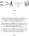
FIG. 1 is a schematic diagram of an exemplary system architecture to which a technical solution according to an embodiment of the present disclosure may be applied. -
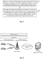
FIG. 2 is a schematic flowchart of a vehicle communication method according to an embodiment of the present disclosure. -
FIG. 3 is a schematic flowchart of a vehicle communication method according to an embodiment of the present disclosure. -
FIG. 4 is a schematic diagram of an application scenario of a vehicle communication method according to an embodiment of the present disclosure. -
FIG. 5 is a schematic diagram of a partial signaling process of a PDU session established between user equipment and a network side device according to an embodiment of the present disclosure. -
FIG. 6 is a schematic block diagram of a vehicle communication apparatus according to an embodiment of the present disclosure. -
FIG. 7 is a schematic block diagram of a vehicle communication apparatus according to an embodiment of the present disclosure. -
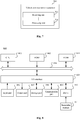
FIG. 8 is a schematic structural diagram of a computer system adapted to implement an electronic device according to an embodiment of the present disclosure. - At present, exemplary embodiments are described more comprehensively with reference to the accompanying drawings. The exemplary embodiments can be implemented in various forms, and should not be understood as being limited to the examples described herein. On the contrary, the embodiments are provided to make the present disclosure more comprehensive and complete, and comprehensively convey the idea of the exemplary embodiments to a person skilled in the art.
- In addition, the described features, structures, or characteristics may be combined in one or more embodiments in any appropriate manner. In the following descriptions, a lot of specific details are provided to facilitate a full understanding of the embodiments of the present disclosure. However, a person of ordinary skill in the art is to be aware that, the technical solutions in the present disclosure may be implemented without one or more of the particular details, or other methods, unit, apparatus, or step may be adopted. In other cases, well-known methods, apparatuses, implementations, or operations are not shown or described in detail, to avoid obscuring aspects of the present disclosure.
- The block diagrams shown in the accompany drawings illustrate merely functional entities and do not necessarily correspond to physically independent entities. That is, such functional entities may be implemented in the form of software, or implemented in one or more hardware modules or integrated circuits, or implemented in different networks and/or processor apparatuses and/or microcontroller apparatuses.
- The flowcharts shown in the accompanying drawings are merely exemplary and do not necessarily include all of the content and operations/steps, nor are steps in the flowcharts necessarily performed in the order described. For example, some operations/steps may be divided, and some operations/steps may be combined or partially combined. Therefore, an actual execution order may be changed according to the actual situation.
-
FIG. 1 is a schematic diagram of an exemplary system architecture to which a technical solution according to an embodiment of the present disclosure may be applied. - As shown is
FIG. 1 , the system architecture may include avehicle terminal 101, abase station 102, acore network device 103 and anapplication server 104. Thecore network device 103 may be an AMF in a 5G core network or the like. - It is to be understood that the number of
vehicle terminals 101, the number of thebase stations 102, the number ofcore network devices 103 and the number ofapplication servers 104 shown inFIG. 1 are merely schematic. According to an implementation requirement, there may be any number ofvehicle terminals 101, any number ofbase stations 102, any number ofcore network devices 103 and any number ofapplication servers 104. - In an embodiment of the present disclosure, a network side device (the
base station 102, thecore network device 103 or theapplication server 104 shown inFIG. 1 ) receives a connection establishment request transmitted by thevehicle terminal 101. If the connection establishment request carries identification information of multiple network slices and the multiple network slices are determined to correspond to a same vehicle communication service, the network side device may establish a PDU session with thevehicle terminal 101, so that thevehicle terminal 101 can support more network slices by establishing multiple PDU sessions. The number of network slices corresponds to the number of V2X use cases, thereby increasing the number of V2X use cases that can be supported by the user equipment, and being beneficial to a promotion and a deployment of an Internet of Vehicles solution. - In another embodiment of the present disclosure, a network side device (the
base station 102, thecore network device 103 or theapplication server 104 shown inFIG. 1 ) receives a connection establishment request transmitted by thevehicle terminal 101. If the connection establishment request carries identification information of a virtual bundled network slice, the network side device may determine identification information of multiple network slices corresponding to the virtual bundled network slice according to the identification information of the virtual bundled network slice, to establish a PDU session with thevehicle terminal 101 based on the multiple network slices, so that thevehicle terminal 101 can support more network slices by using the virtual bundled network slice corresponding to the multiple network slices. The number of network slices corresponds to the number of V2X use cases, thereby increasing the number of V2X use cases that can be supported by the user equipment, and being beneficial to a promotion and a deployment of an Internet of Vehicles solution. - The implementation details of the technical solutions of the embodiments of the present disclosure are described in detail as follows:
-
FIG. 2 is a schematic flowchart of a vehicle communication method according to an embodiment of the present disclosure. The vehicle communication method may be performed by a network side device. For example, the vehicle communication method may be performed by a base station, a core network device, or an application server located at a network edge. Referring toFIG. 2 , the vehicle communication method includes at least S210 to S230. A detailed description is as follows, - In S210, a connection establishment request transmitted by user equipment is received. The connection establishment request carries identification information of multiple network slices.
- In an embodiment of the present disclosure, the user equipment may be a vehicle terminal, and the connection establishment request transmitted by the user equipment may be a request for establishing a PDU session. Identification information of a network slice may be single network slice selection assistance information (S-NSSAI).
- In an embodiment of the present disclosure, before the connection establishment request transmitted by the user equipment is received, the network side device may transmit available network slice information (such as Allowed NSSAI) to the user equipment. The available network slice information includes the identification information of the multiple network slices, so as to help the user equipment to select from the available network slice information.
- In an embodiment of the present disclosure, in order to distinguish from the current solution in which identification information of only one network slice is carried in a message transmitted by the user equipment (such as Rel-15 MSG5 RRC Setup Complete), the identification information of the multiple network slices carried in the connection establishment request in the embodiments of the present disclosure may include the following configurations.
- In an embodiment of the present disclosure, values of the identification information of the multiple network slices are in a predetermined interval, to indicate that the multiple network slices correspond to a same PDU session. The predetermined interval is required to be different from an interval of values of identification information of a common network slice (that is, a network slice carried in a message transmitted by user equipment in the current solution).
- In an embodiment of the present disclosure, an SST field in the identification information of the multiple network slices includes an indicator bit, to indicate that the multiple network slices correspond to the same PDU session.
- In an embodiment of the present disclosure, an SD field in the identification information of the multiple network slices includes an indicator bit, to indicate that the multiple network slices correspond to the same PDU session.
- In an embodiment of the present disclosure, the multiple network slices may correspond to the same AMF and the same UPF.
- Still referring to
FIG. 2 , in S220, it is determined whether the multiple network slices correspond to the same vehicle communication service according to the identification information of the multiple network slices. - In an embodiment of the present disclosure, in a case that the network side device receives the connection establishment request carrying identification information of the multiple network slices, it is determined whether the multiple network slices correspond to the same vehicle communication service according to an indication of a service request message included in the connection establishment request.
- Still referring to
FIG. 2 , in S230, in a case that the multiple network slices are determined to correspond to the same vehicle communication service, a PDU session is established with the user equipment. - With the technical solution of the embodiment shown in
FIG. 2 , the multiple network slices share one PDU session, so that the user equipment can support more network slices by establishing multiple PDU sessions. The number of network slices corresponds to the number of V2X use cases, thereby increasing the number of V2X use cases that can be supported by the user equipment, and being beneficial to a promotion and a deployment of an Internet of Vehicles solution. - Based on the technical solution of the embodiment shown in
FIG. 2 , in an embodiment of the present disclosure, after the network side device establishes a PDU session with the user equipment, different network slices or different V2X use cases correspond to different QoS flows in the established PDU session. - In an embodiment of the present disclosure, if different network slices or different V2X use cases correspond to different QoS flows, the different QoS flows may be isolated by using a GTP-U protocol, a VPN, or a bandwidth management mechanism.
- In an embodiment of the present disclosure, to isolate different network slices from each other, the network side device performs scheduling to ensure that the user equipment uses different wireless transmission resources for different network slices. The wireless transmission resources include a time domain resource and a frequency domain resource.
- In another embodiment of the present disclosure, to isolate different network slices from each other, alternatively, wireless transmission resource pools may be configured for different network slices, so that the user equipment uses different wireless transmission resources for different network slices. A priority and a size of the wireless transmission resource pool have a positive correlation with a priority of the network slice corresponding to the wireless transmission resource pool, and the size of the wireless transmission resource pool has a positive correlation with the priority of the network slice corresponding to the wireless transmission resource pool. For example, if the priority and/or size of the wireless transmission resource pool increases, the priority of the network slice corresponding to the wireless transmission resource pool becomes higher.
- In an embodiment of the present disclosure, in a case that the wireless transmission resource pools are configured for different network slices, configuration signaling may be transmitted to the user equipment, to configure the wireless transmission resource pools corresponding to the different network slices for the user equipment, or pre-configure the wireless transmission resource pools corresponding to the different network slices for the user equipment.
- In an embodiment of the present disclosure, in a case that the wireless transmission resource pools corresponding to the different network slices are configured for the user equipment by using the configuration signaling, the configuration signaling may indicate the wireless transmission resource pools corresponding to the different network slices in an explicit or implicit manner. Optionally, in the explicit manner, the wireless transmission resource pools corresponding to the different network slices are directly indicated. In the implicit manner, multiple wireless transmission resource pools are indicated in an order. The multiple wireless transmission resource pools respectively correspond to different network slices.
- In an embodiment of the present disclosure, the foregoing configuration signaling may be Radio Resource Control (RRC) signaling or non-access stratum (NAS) signaling.
- In an embodiment of the present disclosure, the number of network slices supported by the user equipment may be expanded by expanding the number of data radio bearers (DRBs).
-
FIG. 3 is a schematic flowchart of a vehicle communication method according to an embodiment of the present disclosure. The vehicle communication method may be performed by a network side device. For example, the vehicle communication method may be performed by a base station, a core network device, or an application server located at a network edge. Referring toFIG. 3 , the vehicle communication method includes at least S310 and S320. A detailed description is as follows. - In step S310, a connection establishment request transmitted by user equipment is received. The connection establishment request carries identification information of a virtual bundled network slice.
- In an embodiment of the present disclosure, the user equipment may be a vehicle terminal, and the connection establishment request transmitted by the user equipment may be a request for establishing a PDU session. Identification information of a network slice may be S-NSSAI.
- In an embodiment of the present disclosure, the virtual bundled network slice corresponds to multiple real network slices. Multiple real network slices are bundled to obtain a virtual network slice corresponding to the multiple real network slices, and the virtual network slice is referred to as the virtual bundled network slice. Identification information of the virtual bundled network slice may also be S-NSSAI.
- In an embodiment of the present disclosure, before receiving the connection establishment request transmitted by the user equipment, the network side device may transmit available network slice information (such as Allowed NSSAI) to the user equipment. The available network slice information includes the identification information of the virtual bundled network slice, so as to help the user equipment to select from the available network slice information.
- In an embodiment of the present disclosure, in order to distinguish from the current solution in which identification information of only one network slice is carried in a message transmitted by the user equipment (such as Rel-15 MSG5 RRC Setup Complete), the identification information of the virtual bundled network slice carried in the connection establishment request in the embodiments of the present disclosure may include the following configurations.
- In an embodiment of the present disclosure, values of the identification information of the virtual bundled network slice are in a predetermined interval, to indicate that the virtual bundled network slice corresponds to the multiple network slices. The predetermined interval is required to be different from an interval of values of identification information of a common network slice (that is, a network slice carried in a message transmitted by user equipment in the current solution).
- In an embodiment of the present disclosure, an SST field in the identification information of the virtual bundled network slice includes an indicator bit, to indicate that the virtual bundled network slice corresponds to the multiple network slices.
- In an embodiment of the present disclosure, an SD field in the identification information of the virtual bundled network slice includes an indicator bit, to indicate that the virtual bundled network slice corresponds to the multiple network slices.
- Still referring to
FIG. 3 , in step S320, identification information of multiple network slices corresponding to the virtual bundled network slice is determined according to the identification information of the virtual bundled network slice, to establish a PDU session with the user equipment based on the multiple network slices. - In an embodiment of the present disclosure, the identification information of the multiple network slices corresponding to the virtual bundled network slice may be determined according to a pre-configured correspondence.
- In an embodiment of the present disclosure, when the PDU session between the network side device and the user equipment is to be established based on the multiple network slices corresponding to the virtual bundled network slice, one network slice may correspond to one PDU session, or multiple network slices may correspond to one PDU session.
- With the technical solution provided by the embodiment shown in
FIG. 3 , the user equipment can support more network slices by using the virtual bundled network slice corresponding to the multiple network slices. The number of network slices corresponds to the number of vehicle communication use cases, thereby increasing the number of vehicle communication use cases that can be supported by the user equipment, and being beneficial to a promotion and a deployment of an Internet of Vehicles solution. - In an application scenario of 5G Internet of Vehicles, the implementation details of the technical solutions of the embodiments of the present disclosure are described in detail as follows.
- In the embodiments of the present disclosure, in the application scenario of 5G Internet of Vehicles, for a case that V2X use cases include different QoS requirements, the V2X use cases need to be isolated from each other through slicing to ensure reliable transmission due to V2X security involved, and the number of V2X use cases is greater than an upper limit allowed by the UE, technical solutions of the following embodiments may be used.
- Embodiment 1: Expand the number of network slices that can be supported in parallel by the UE.
- According to 3GPP Rel-15, the number of network slices supported by the UE is limited in consideration of the number of DRBs and a restriction that introduced network slices have to use different PDU sessions on a radio access network (RAN) side to reduce the impact on specifications on the RAN side. In the embodiments of the present disclosure, the number of network slices that can be supported by the UE may be expanded by expanding the number of DRBs. For example, the number of DRBs may be expanded to 32, and thus the number of slices supported by the UE may also be expanded to 32.
- Embodiment 2: Introduce a mechanism that multiple network slices share one PDU session.
- In an embodiment of the present disclosure, network slices that support sharing of a PDU session may be introduced, that is, multiple network slices are carried by using the same PDU session. When this solution is to be used, the following condition should be met: AMFs corresponding to different V2X use cases/network slices are the same, and UPFs corresponding to different V2X use cases/network slices are the same as well.
- In an embodiment of the present disclosure, all of the multiple network slices sharing the PDU session need to be embodied in allowed NSSAI.
- In an embodiment of the present disclosure, the multiple network slices sharing the PDU session need to be identified and distinguished from other network slices (that is, network slices that share no PDU session) at a protocol level.
- In an embodiment of the present disclosure, if the network slices sharing the PDU session still use 24-bits of S-NSSAI, different ways may be used for distinguishing. Optionally, an interval of values of the S-NSSAI of the network slices sharing the PDU session may be separated from that of S-NSSAI of a common network slice; or an indicator bit area may be introduced, such as defining a new SST, to add a corresponding identification bit to the new SST; or a corresponding identification bit may be added to an SD part for distinguishing.
- In an embodiment of the present disclosure, a connection establishment process of the multiple network slices sharing the PDU session is different from that of the common network slice. Specifically, different from a solution provided by the 3GPP Rel-15 that an MSG5 RRC Setup Complete message carries only one piece of S-NSSAI to be selected by an AMF, in the technical solutions of the embodiments of the present disclosure, when the UE initiates the connection establishment request to the network side device, an MSG5 message may carry multiple pieces of S-NSSAI. When the network side device (such as the base station or the AMF) receives the MSG5 message including the multiple pieces of S-NSSAI, a new function needs to be introduced to identify whether the multiple pieces of S-NSSAI belong to the same V2X service (for example, it is determined whether the multiple pieces of S-NSSAI belong to the same V2X service based on an indication of a service request message included in the MSG5 message), and then establishment of only one PDU session is triggered.
- In an embodiment of the present disclosure, as shown in
FIG. 4 , after one PDU session is established for multiple pieces of S-NSSAI, different V2X use cases/network slices may establish different QoS flows. A 5G core network device may isolate different QoS flows from each other through a GTP-U tunnel, a VPN or a bandwidth management mechanism. - In addition, in an embodiment of the present disclosure, a wireless side (such as a base station gNB) may isolate different network slices from each other in a manner of scheduling. Alternatively, the wireless side may configure corresponding shared resource pools for different network slices, to isolate different network slices from each other. Priorities and the sizes of the shared resource pools configured by the wireless side may embody priorities of different slices. Furthermore, the wireless side may configure the shared resource pools corresponding to different network slices by using signaling (such as RRC signaling or NAS signaling) or in a manner of pre-configuration, and a correspondence between a network slice and a shared resource pool may be explicitly given in configuration signaling or may be implicitly given at intervals.
- Based on the technical solution of embodiment 2, in an embodiment of the present disclosure, a partial signaling process of establishing a PDU session between a user equipment and a network side device may be shown in
FIG. 5 . Interaction signaling (such as an RRC message) between the user equipment and a base station includes information about a network slice, and the process may include the following steps S501 to S508. - In S501, the base station transmits an NG establishment request to an AMF1. The NG establishment request carries a list of supported S-NSSAI.
- In S502, the AMF1 returns an NG establishment response message to the base station. The NG establishment response message carries the list of supported S-NSSAI.
- In S503, the base station transmits an NG establishment request to an AMF2. The NG establishment request carries a list of supported S-NSSAI.
- In S504, the AMF2 returns an NG establishment response message to the base station. The NG establishment response message carries the list of supported S-NSSAI.
- In S505, an RRC connection is established between the base station and the user equipment.
- In S506, the base station identifies a network slicing strategy and identifies a core network (CN) node that supports a relevant network slice; or the base station selects a default CN node. Specifically, the network slicing strategy identified by the base station is to identify whether multiple network slices need to be carried by using the same PDU session.
- In S507, the base station transmits an initial UE message to the AMF1.
- In S508, the AMF1 verifies permission of the UE and availability of a network slice.
- Embodiment 3: Introduce a virtual bundled network slice.
- In an embodiment of the present disclosure, network slices of multiple V2X use cases correspond to one virtual bundled network slice. A correspondence between the virtual bundled network slice and the network slices of the multiple V2X use cases may be maintained only on the network side.
- In an embodiment of the present disclosure, the virtual bundled network slice needs to be identified and distinguished from other network slices (that is, network slices that are not virtually bundled) at a protocol level.
- In an embodiment of the present disclosure, if the virtual bundled network slice still uses 24-bits of S-NSSAI, different ways may be used for distinguishing. Optionally, an interval of values of the S-NSSAI of the virtual bundled network slice may be separated from that of S-NSSAI of a common network slice; or an indicator bit area may be introduced, such as defining a new SST, to add a corresponding identification bit to the new SST; or a corresponding identification bit may be added to an SD part for distinguishing.
- In an embodiment of the present disclosure, information about the virtual bundled network slice may be maintained only on the network side. This embodiment is the same as the network slices sharing the PDU session (that is, the foregoing embodiment 2) in that, the network slices corresponding to different V2X use cases are still maintained in the core network. However, in this embodiment, the UE on the wireless side is unnecessary to maintain the network slices corresponding to all the V2X use cases in allowed NSSAI, only the virtual bundled network slice may be included in the allowed NSSAI, and thus network slices corresponding to multiple V2X use cases are bundled into one on the wireless side.
- In an embodiment of the present disclosure, a connection establishment process of the virtual bundled network slice may be different from that of the common network slice. Specifically, different from a solution provided by the 3GPP Rel-15 that an MSG5 RRC Setup Complete message carries only one piece of S-NSSAI to be selected by an AMF, in the technical solutions of the embodiments of the present disclosure, when the UE initials the connection establishment request to the network side device, an MSG5 message carries only one virtual bundled network slice. When the network side device (such as the base station or the AMF) receives the virtual bundled network slice in the MSG5 message, a new function needs to be introduced to identify the network slices of the multiple V2X use cases corresponding to the virtual bundled network slice, for example, identifying according to a correspondence between the virtual bundled network slice and the network slices of the V2X use cases.
- In an embodiment of the present disclosure, since the network side device (such as the base station or the AMF) can determine the correspondence between the virtual bundled network slice and the network slices of the multiple V2X use cases, the isolation between the network slices can still be guaranteed.
- Based on the technical solution of embodiment 3, in an embodiment of the present disclosure, a partial signaling process of establishing a PDU session between a user equipment and a network side device may also be shown in
FIG. 5 . In S506, the network slicing strategy identified by the base station is to identify the network slices of the multiple V2X use cases corresponding to the virtual bundled network slice. - The technical solutions of the foregoing embodiments of the present disclosure are applicable to an implementation scenario of a deployment based on a network slice in future 5G Internet of Vehicles and automatic driving. With the technical solutions, a limitation problem of network slices put forward in the 3GPP Rel-15 can be effectively resolved, thereby increasing the number of V2X use cases that can be supported by the user equipment, enabling the V2X use cases to implement an isolation by using a network slicing mechanism, and thus being beneficial to a promotion and a deployment of an Internet of Vehicles solution.
- Apparatus embodiments of the present disclosure are described below, and the apparatus may be used for performing the vehicle communication method in the foregoing embodiments of the present disclosure. For details not disclosed in the apparatus embodiments of the present disclosure, one may refer to the foregoing vehicle communication method embodiments of the present disclosure.
-
FIG. 6 is a schematic block diagram of a vehicle communication apparatus according to an embodiment of the present disclosure. - Referring to
FIG. 6 , avehicle communication apparatus 600 according to an embodiment of the present disclosure includes: a receivingunit 602, a determiningunit 604, and aprocessing unit 606. - The receiving
unit 602 is configured to receive a connection establishment request transmitted by user equipment. The connection establishment request carries identification information of multiple network slices. The determiningunit 604 is configured to determine whether the multiple network slices correspond to a same vehicle communication service according to the identification information of the multiple network slices. Theprocessing unit 606 is configured to establish, in a case that the multiple network slices are determined to correspond to the same vehicle communication service, a PDU session with the user equipment. - In an embodiment of the present disclosure, values of the identification information of the multiple network slices are in a predetermined interval, to indicate that the multiple network slices correspond to the same PDU session; or an SST field in the identification information of the multiple network slices includes an indicator bit, to indicate that the multiple network slices correspond to the same PDU session; or an SD field in the identification information of the multiple network slices includes an indicator bit, to indicate that the multiple network slices correspond to the same PDU session.
- In an embodiment of the present disclosure, the
processing unit 606 is further configured to control, in the PDU session, different network slices or different use cases to correspond to different QoS flows. - In an embodiment of the present disclosure, the
processing unit 606 is further configured to isolate the different QoS flows by using a GTP-U protocol, a VPN, or a bandwidth management mechanism. - In an embodiment of the present disclosure, the
vehicle communication apparatus 600 further includes a scheduling unit, configured to schedule the user equipment to use different wireless transmission resources for different network slices. - In an embodiment of the present disclosure, the
vehicle communication apparatus 600 further includes a configuration unit, configured to configure wireless transmission resource pools for different network slices, so that the user equipment uses different wireless transmission resources for different network slices. A priority of the wireless transmission resource pool has a positive correlation with a priority of the network slice corresponding to the wireless transmission resource pool, and a size of the wireless transmission resource pool has a positive correlation with the priority of the network slice corresponding to the wireless transmission resource pool. - In an embodiment of the present disclosure, the configuration unit is configured to transmit configuration signaling to the user equipment, to configure the wireless transmission resource pools corresponding to the different network slices for the user equipment, or pre-configure the wireless transmission resource pools corresponding to the different network slices for the user equipment.
- In an embodiment of the present disclosure, the configuration unit is configured to indicate the wireless transmission resource pools corresponding to the different network slices in an explicit or implicit manner, by using the configuration signaling transmitted to the user equipment.
- In an embodiment of the present disclosure, the
vehicle communication apparatus 600 further includes a transmission unit, configured to transmit available network slice information to the user equipment. The available network slice information includes the identification information of the multiple network slices. - In an embodiment of the present disclosure, the multiple network slices correspond to a same AMF and a same UPF.
- In an embodiment of the present disclosure, the
vehicle communication apparatus 600 further includes an expansion unit, configured to expand the number of data radio bearers, to expand the number of network slices supported by the user equipment. -
FIG. 7 is a schematic block diagram of a vehicle communication apparatus according to an embodiment of the present disclosure. - Referring to
FIG. 7 , avehicle communication apparatus 700 according to an embodiment of the present disclosure includes: a receivingunit 702 and aprocessing unit 704. - The receiving
unit 702 is configured to receive a connection establishment request transmitted by user equipment. The connection establishment request carries identification information of a virtual bundled network slice. Theprocessing unit 704 is configured to determine identification information of multiple network slices corresponding to the virtual bundled network slice according to the identification information of the virtual bundled network slice, to establish a PDU session with the user equipment based on the multiple network slices. - In an embodiment of the present disclosure, the
processing unit 704 is configured to determine the identification information of the multiple network slices corresponding to the virtual bundled network slice according to a pre-configured correspondence. - In an embodiment of the present disclosure, the
vehicle communication apparatus 700 further includes a transmission unit, configured to transmit available network slice information to the user equipment. The available network slice information includes the identification information of the virtual bundled network slice. - In an embodiment of the present disclosure, values of the identification information of the virtual bundled network slice are in a predetermined interval, to indicate that the virtual bundled network slice corresponds to the multiple network slices; or an SST field in the identification information of the virtual bundled network slice includes an indicator bit, to indicate that the virtual bundled network slice corresponds to the multiple network slices; or an SD field in the identification information of the virtual bundled network slice includes an indicator bit, to indicate that the virtual bundled network slice corresponds to the multiple network slices.
-
FIG. 8 is a schematic structural diagram of a computer system adapted to implement an electronic device according to an embodiment of the present disclosure. - A
computer system 800 of the electronic device shown inFIG. 8 is only schematic, and is not intended to impose any restriction on functions and scopes of use of the embodiments of the present disclosure. - As shown in
FIG. 8 , thecomputer system 800 includes a central processing unit (CPU) 801. TheCPU 801 may perform various proper actions and processing according to a program stored in a read-only memory (ROM) 802 or a program loaded from astorage part 808 into a random access memory (RAM) 803. TheRAM 803 further stores various programs and data required for system operations. TheCPU 801, theROM 802, and theRAM 803 are connected to each other through abus 804. An input/output (I/O)interface 805 is also connected to thebus 804. - The following components are connected to the I/O interface 805: an
input part 806 including a keyboard, a mouse, or the like, anoutput part 807 including a cathode ray tube (CRT), a liquid crystal display (LCD), a speaker, or the like, astorage part 808 including a hard disk, or the like, and acommunication part 809 including a network interface card such as a local area network (LAN) card or a modem. Thecommunication part 809 performs a communication processing over a network such as the Internet. Adriver 810 is also connected to the I/O interface 805 as required. Aremovable medium 811 such as a magnetic disk, an optical disc, a magneto-optical disk, or a semiconductor memory is installed on thedriver 810 as required, so that a computer program read from theremovable medium 811 is installed into thestorage part 808 as required. - Particularly, according to the embodiments of the present disclosure, the processes described below by referring to the flowcharts may be implemented as computer software programs. For example, according to an embodiment of the present disclosure, a computer program product is provided. The computer program product includes a computer program carried on a computer-readable medium, and the computer program includes program codes used for performing the methods shown in the flowcharts. In such embodiment, the computer program may be downloaded and installed through the
communication part 809 from a network, and/or installed from theremovable medium 811. When the computer program is executed by theCPU 801, various functions defined in the system of the present disclosure are executed. - The computer-readable medium shown in the embodiments of the present disclosure may be a computer-readable signal medium or a computer-readable storage medium or any combination thereof. The computer-readable storage medium may be, for example, but is not limited to, an electric, a magnetic, an optical, an electromagnetic, an infrared, or a semi-conductive system, apparatus, or device, or any combination thereof. A more specific example of the computer-readable storage medium may include but is not limited to: an electrical connection including one or more wires, a portable computer magnetic disk, a hard disk, a RAM, a ROM, an erasable programmable read-only memory (EPROM), a flash memory, an optical fiber, a portable compact disc read-only memory (CD-ROM), an optical storage device, a magnetic storage device, or any appropriate combination thereof. In the present disclosure, the computer-readable storage medium may be any tangible medium including or storing a program, and the program may be used by or used in combination with an instruction execution system, an apparatus, or a device. In the present disclosure, a computer-readable signal medium may include a data signal propagated in a baseband or as part of a carrier, and stores computer-readable program code. Such a propagated data signal may be in multiple forms, including but not limited to an electromagnetic signal, an optical signal, or any suitable combination thereof. The computer-readable signal medium may be further any computer-readable medium in addition to the computer-readable storage medium. The computer-readable medium may send, propagate, or transmit a program configured to be used by or in combination with an instruction execution system, an apparatus, or a device. The program code included in the computer-readable medium may be transmitted by using any suitable medium, including but not limited to: a wireless medium, a wired medium, or the like, or any suitable combination thereof.
- The flowcharts and block diagrams in the accompanying drawings illustrate possible system architectures, functions and operations that may be implemented by the system, the method, and the computer program product according to various embodiments of the present disclosure. In this aspect, each box in a flowchart or a block diagram may represent a module, a program segment, or a part of code. The module, the program segment, or the part of code includes one or more executable instructions used for implementing specified logic functions. In some alternative implementations, functions annotated in the boxes may be implemented in a sequence different from that annotated in the accompanying drawings. For example, operations in two connected boxes may be performed substantially in parallel, and the operations in the two connected boxes may be performed in a reverse sequence, depending on a related function. Each box in a block diagram or a flowchart and a combination of boxes in the block diagram or the flowchart may be implemented by using a dedicated hardware-based system configured to perform a specified function or an operation, or may be implemented by using a combination of dedicated hardware and a computer instruction.
- A related unit described in the embodiments of the present disclosure may be implemented in a software manner, or may be implemented in a hardware manner, and the unit described may also be provided in a processor. Names of the units do not constitute a limitation on the units in a specific case.
- According to another aspect, a computer-readable medium is further provided according to the present disclosure. The computer-readable medium may be included in the electronic device described in the foregoing embodiments, or may exist alone and is not arranged in the electronic device. The computer-readable medium carries one or more programs, the one or more programs, when being executed by the electronic device, cause the electronic device to implement the method described in the foregoing embodiments.
- Although multiple modules or units of a device configured to perform actions are mentioned in the foregoing detailed description, such division is not mandatory. Actually, according to the embodiments of the present disclosure, the features and functions of two or more modules or units described above may be integrated in one module or unit. Conversely, features and functions of one module or unit described above may be implemented by multiple modules or units.
- Through the descriptions of the foregoing implementations, a person skilled in the art readily understands that the exemplary embodiments described herein may be implemented by using software, or may be implemented by using software in combination with necessary hardware. Therefore, the technical solutions of the embodiments of the present disclosure may be implemented in a form of a software product. The software product may be stored in a non-volatile storage medium (which may be a CD-ROM, a USB flash drive, a removable hard disk, or the like) or on the network. The software product includes multiple instructions for instructing a computing device (which may be a personal computer, a server, a touch terminal, a network device, or the like) to perform the methods according to the embodiments of the present disclosure.
- After considering the specification and practicing the present disclosure, a person skilled in the art can readily conceive other implementations of the present disclosure. The present disclosure is intended to cover any variations, uses or adaptation of the present disclosure following the general principles of the present disclosure, and includes the well-known knowledge and conventional technical means in the art undisclosed in the present disclosure.
- It is to be understood that the present disclosure is not limited to the accurate structures that are described above and are shown in the accompanying drawings, and modifications and changes may be made without departing from the scope of the present disclosure. The scope of the present disclosure is defined by the appended claims only.
Claims (15)
- A vehicle communication method, characterized in that the method comprises:receiving, by a network side device, a connection establishment request transmitted by user equipment, wherein the connection establishment request carries identification information of a plurality of network slices;determining, by the network side device, whether the plurality of network slices correspond to a same vehicle communication service according to the identification information of the plurality of network slices; andestablishing, by the network side device in a case that the plurality of network slices are determined to correspond to the same vehicle communication service, a protocol data unit, PDU, session with the user equipment.
- The vehicle communication method according to claim 1, wherein values of the identification information of the plurality of network slices are in a predetermined interval, to indicate that the plurality of network slices correspond to the same PDU session; or
a slice/service type, SST, field in the identification information of the plurality of network slices comprises an indicator bit, to indicate that the plurality of network slices correspond to the same PDU session; or
a slice differentiator, SD, field in the identification information of the plurality of network slices comprises an indicator bit, to indicate that the plurality of network slices correspond to the same PDU session. - The vehicle communication method according to claim 1, wherein in the PDU session, different network slices or different vehicle communication use cases correspond to different quality of service flows, QoS flows,.
- The vehicle communication method according to claim 3, further comprising:
isolating, by the network side device, the different QoS flows by using a GPRS tunnel protocol user plane, GTP-U, a virtual private network, VPN, or a bandwidth management mechanism. - The vehicle communication method according to claim 1, further comprising:
scheduling, by the network side device, the user equipment to use different wireless transmission resources for different network slices. - The vehicle communication method according to claim 1, further comprising:
configuring, by the network side device, wireless transmission resource pools for different network slices, so that the user equipment uses different wireless transmission resources for different network slices, wherein a priority of the wireless transmission resource pool has a positive correlation with a priority of the network slice corresponding to the wireless transmission resource pool, and a size of the wireless transmission resource pool has a positive correlation with the priority of the network slice corresponding to the wireless transmission resource pool. - The vehicle communication method according to claim 6, wherein the configuring, by the network side device, wireless transmission resource pools for different network slices comprises:transmitting, by the network side device, configuration signaling to the user equipment, to configure the wireless transmission resource pools corresponding to the different network slices for the user equipment; orpre-configuring, by the network side device, the wireless transmission resource pools corresponding to the different network slices for the user equipment.
- A vehicle communication method, characterized in that the method comprises:receiving, by a network side device, a connection establishment request transmitted by user equipment, wherein the connection establishment request carries identification information of a virtual bundled network slice;determining, by the network side device, identification information of a plurality of network slices corresponding to the virtual bundled network slice according to the identification information of the virtual bundled network slice; andestablishing, by the network side device, a protocol data unit, PDU, session with the user equipment based on the plurality of network slices.
- The vehicle communication method according to claim 8, wherein the determining, by the network side device, identification information of a plurality of network slices corresponding to the virtual bundled network slice according to the identification information of the virtual bundled network slice comprises:
determining, by the network side device, the identification information of the plurality of network slices corresponding to the identification information of the virtual bundled network slice according to a pre-configured correspondence. - The vehicle communication method according to claim 8, wherein
values of the identification information of the virtual bundled network slice are in a predetermined interval, to indicate that the virtual bundled network slice corresponds to the plurality of network slices; or
a slice/service type, SST, field in the identification information of the virtual bundled network slice comprises an indicator bit, to indicate that the virtual bundled network slice corresponds to the plurality of network slices; or
a slice differentiator, SD, field in the identification information of the virtual bundled network slice comprises an indicator bit, to indicate that the virtual bundled network slice corresponds to the plurality of network slices. - A vehicle communication apparatus, characterized in that the apparatus comprises:a receiving unit, configured to receive a connection establishment request transmitted by user equipment, wherein the connection establishment request carries identification information of a plurality of network slices;a determining unit, configured to determine whether the plurality of network slices correspond to a same vehicle communication service according to the identification information of the plurality of network slices; anda processing unit, configured to establish, in a case that the plurality of network slices are determined to correspond to the same vehicle communication service, a protocol data unit, PDU, session with the user equipment.
- A vehicle communication apparatus, characterized in that the apparatus comprises:a receiving unit, configured to receive a connection establishment request transmitted by user equipment, wherein the connection establishment request carries identification information of a virtual bundled network slice; anda processing unit, configured to determine identification information of a plurality of network slices corresponding to the virtual bundled network slice according to the identification information of the virtual bundled network slice, to establish a protocol data unit, PDU, session with the user equipment based on the plurality of network slices.
- A computer-readable medium storing a computer program, wherein the computer program, when being executed by a processor, implements the vehicle communication method according to any one of claims 1 to 7; or implements the vehicle communication method according to any one of claims 8 to 10.
- An electronic device, comprising:one or more processors; anda storage apparatus, configured to store one or more programs, wherein the one or more programs, when being executed by the one or more processors, cause the one or more processors to implement the vehicle communication method according to any one of claims 1 to 7; or implement the vehicle communication method according to any one of claims 8 to 10.
- A computer program product comprising instructions, wherein the instructions, when being run on a computer, cause the computer to perform the vehicle communication method according to any one of claims 1 to 7, or cause the computer to perform the vehicle communication method according to any one of claims 8 to 10.
Applications Claiming Priority (2)
| Application Number | Priority Date | Filing Date | Title |
|---|---|---|---|
| CN201811169725.8A CN109040322B (en) | 2018-10-08 | 2018-10-08 | Vehicle communication method, apparatus, computer readable medium and electronic device |
| PCT/CN2019/091809 WO2020073678A1 (en) | 2018-10-08 | 2019-06-19 | Vehicle communication method, device, computer readable medium and electronic device |
Publications (3)
| Publication Number | Publication Date |
|---|---|
| EP3761608A1 true EP3761608A1 (en) | 2021-01-06 |
| EP3761608A4 EP3761608A4 (en) | 2021-07-14 |
| EP3761608B1 EP3761608B1 (en) | 2025-01-15 |
Family
ID=64615768
Family Applications (1)
| Application Number | Title | Priority Date | Filing Date |
|---|---|---|---|
| EP19871415.6A Active EP3761608B1 (en) | 2018-10-08 | 2019-06-19 | Vehicle communication method, device, computer readable medium and electronic device |
Country Status (5)
| Country | Link |
|---|---|
| US (1) | US11445522B2 (en) |
| EP (1) | EP3761608B1 (en) |
| JP (1) | JP7058833B2 (en) |
| CN (1) | CN109040322B (en) |
| WO (1) | WO2020073678A1 (en) |
Families Citing this family (13)
| Publication number | Priority date | Publication date | Assignee | Title |
|---|---|---|---|---|
| CN109040322B (en) | 2018-10-08 | 2021-05-11 | 腾讯科技(深圳)有限公司 | Vehicle communication method, apparatus, computer readable medium and electronic device |
| CN113475039B (en) * | 2019-01-30 | 2023-02-03 | 华为技术有限公司 | Apparatus and method for network and/or management function adaptation based on open information |
| CN113261361B (en) * | 2019-03-28 | 2023-04-11 | 华为技术有限公司 | Control unit and method for secondary sidelink communication |
| EP4061024B1 (en) * | 2019-12-31 | 2023-11-22 | Huawei Technologies Co., Ltd. | D2d communication method and apparatus |
| CN111294762B (en) * | 2020-01-23 | 2021-04-13 | 北京邮电大学 | Vehicle service processing method based on radio access network RAN slice collaboration |
| CN113285876B (en) * | 2020-02-19 | 2024-04-23 | 中兴通讯股份有限公司 | Routing method, routing device and computer readable storage medium |
| CN111698290B (en) * | 2020-05-19 | 2021-06-15 | 展讯通信(天津)有限公司 | PDU session multiplexing method, device, user equipment and storage medium |
| US11671876B2 (en) * | 2020-05-29 | 2023-06-06 | Dell Products, L.P. | Classifying network traffic to use cellular network slices based on application parameters |
| TWI740713B (en) * | 2020-11-11 | 2021-09-21 | 財團法人工業技術研究院 | Resource management method, resource management system and workload scheduling apparatus for network slicing |
| WO2022257133A1 (en) * | 2021-06-11 | 2022-12-15 | 北京小米移动软件有限公司 | Method and apparatus for establishing shared pdu session among multiple terminals, communication device, and storage medium |
| CN113365245B (en) * | 2021-07-01 | 2024-03-22 | 腾讯科技(深圳)有限公司 | Communication method and device applied to remote driving, medium and electronic equipment |
| CN114257618A (en) * | 2021-12-13 | 2022-03-29 | 航天科技控股集团股份有限公司 | Vehicle operation data real-time analysis system based on Internet of vehicles platform |
| CN118842828A (en) * | 2024-06-27 | 2024-10-25 | 岚图汽车科技有限公司 | Automobile model identification method, device, equipment and storage medium |
Family Cites Families (14)
| Publication number | Priority date | Publication date | Assignee | Title |
|---|---|---|---|---|
| US10512109B2 (en) * | 2016-01-15 | 2019-12-17 | Telefonaktiebolaget Lm Ericsson (Publ) | Transmitting communication device, receiving communication device and methods performed thereby |
| JP6725703B2 (en) | 2016-02-16 | 2020-07-22 | アイディーエーシー ホールディングス インコーポレイテッド | Network slicing operation |
| CN106572516B (en) * | 2016-09-28 | 2021-02-12 | 华为技术有限公司 | Network slice selection method, terminal equipment and network equipment |
| CN108307516B (en) * | 2016-09-30 | 2021-08-13 | 华为技术有限公司 | Data transmission method and related equipment |
| KR102650322B1 (en) * | 2016-11-11 | 2024-03-25 | 광동 오포 모바일 텔레커뮤니케이션즈 코포레이션 리미티드 | Wireless communication methods, terminal devices and network devices |
| JP6889263B2 (en) * | 2017-01-27 | 2021-06-18 | テレフオンアクチーボラゲット エルエム エリクソン(パブル) | Secondary authentication of user equipment |
| US10397892B2 (en) | 2017-02-06 | 2019-08-27 | Huawei Technologies Co., Ltd. | Network registration and network slice selection system and method |
| CN108696905B (en) * | 2017-02-20 | 2023-06-13 | 中兴通讯股份有限公司 | Method and device for managing wireless resources |
| CA3065624C (en) * | 2017-06-19 | 2022-07-26 | Huawei Technologies Co., Ltd. | Registration method, session establishment method, terminal, and amf entity |
| CN113784333B (en) * | 2017-10-16 | 2022-05-24 | 华为技术有限公司 | Method, device and system for mobility management |
| US10797894B2 (en) * | 2017-12-28 | 2020-10-06 | Ofinno, Llc | Service type and device type-based policy and charging control |
| CN110121168B (en) * | 2018-02-06 | 2021-09-21 | 华为技术有限公司 | Security negotiation method and device |
| KR102436652B1 (en) * | 2018-04-05 | 2022-08-29 | 삼성전자 주식회사 | Method and apparatus for supporting vehicle communications in 5g system |
| CN109040322B (en) * | 2018-10-08 | 2021-05-11 | 腾讯科技(深圳)有限公司 | Vehicle communication method, apparatus, computer readable medium and electronic device |
-
2018
- 2018-10-08 CN CN201811169725.8A patent/CN109040322B/en active Active
-
2019
- 2019-06-19 JP JP2020560135A patent/JP7058833B2/en active Active
- 2019-06-19 EP EP19871415.6A patent/EP3761608B1/en active Active
- 2019-06-19 WO PCT/CN2019/091809 patent/WO2020073678A1/en not_active Ceased
-
2020
- 2020-10-20 US US17/075,612 patent/US11445522B2/en active Active
Also Published As
| Publication number | Publication date |
|---|---|
| EP3761608A4 (en) | 2021-07-14 |
| CN109040322B (en) | 2021-05-11 |
| US11445522B2 (en) | 2022-09-13 |
| JP2021519040A (en) | 2021-08-05 |
| CN109040322A (en) | 2018-12-18 |
| JP7058833B2 (en) | 2022-04-25 |
| WO2020073678A1 (en) | 2020-04-16 |
| EP3761608B1 (en) | 2025-01-15 |
| US20210037542A1 (en) | 2021-02-04 |
Similar Documents
| Publication | Publication Date | Title |
|---|---|---|
| EP3761608B1 (en) | Vehicle communication method, device, computer readable medium and electronic device | |
| EP4387186A1 (en) | Computing task policy determination or resource allocation method and apparatus, network element, and medium | |
| CN111491009B (en) | Business collaborative processing method and related equipment | |
| JP7669274B2 (en) | METHOD, DEVICE, COMPUTER PROGRAM, AND ELECTRONIC DEVICE FOR CONTROLLING SERVICE QUALITY OF SIDELINK COMMUNICATION | |
| US10299248B2 (en) | Method and apparatus for transmitting system information, and method and apparatus for receiving system information | |
| WO2015106694A1 (en) | Data transmission method, base station, and user equipment | |
| EP3709686B1 (en) | Data transmission control method and related product | |
| CN108011899B (en) | Session establishment optimization method, device and system | |
| CN116569580A (en) | Method, device and computer readable medium for communication | |
| CN110366254A (en) | A resource determination method, related equipment and system | |
| CN106792497A (en) | Base station, user equipment and its cut-in method | |
| CN108024341B (en) | A scheduling method, terminal and base station | |
| WO2020237510A1 (en) | Control signalling detection method and apparatus, device, and storage medium | |
| CN111836389B (en) | Uplink resource scheduling method, terminal and network side equipment | |
| EP3534661B1 (en) | Internet of vehicles transmission resource acquisition method and terminal | |
| CN115707143B (en) | Random access resource isolation method, equipment and medium for access network slice | |
| US12543241B2 (en) | Control for non-SDT data transmission | |
| CN113728711A (en) | Sidelink realization method and related product | |
| CN111867113B (en) | Uplink resource scheduling method, terminal and network side equipment | |
| EP4135446A1 (en) | Method and device for stopping sending schedule request | |
| HK40027915B (en) | Service collaborative processing method and related apparatus |
Legal Events
| Date | Code | Title | Description |
|---|---|---|---|
| STAA | Information on the status of an ep patent application or granted ep patent |
Free format text: STATUS: THE INTERNATIONAL PUBLICATION HAS BEEN MADE |
|
| PUAI | Public reference made under article 153(3) epc to a published international application that has entered the european phase |
Free format text: ORIGINAL CODE: 0009012 |
|
| STAA | Information on the status of an ep patent application or granted ep patent |
Free format text: STATUS: REQUEST FOR EXAMINATION WAS MADE |
|
| 17P | Request for examination filed |
Effective date: 20201001 |
|
| AK | Designated contracting states |
Kind code of ref document: A1 Designated state(s): AL AT BE BG CH CY CZ DE DK EE ES FI FR GB GR HR HU IE IS IT LI LT LU LV MC MK MT NL NO PL PT RO RS SE SI SK SM TR |
|
| AX | Request for extension of the european patent |
Extension state: BA ME |
|
| A4 | Supplementary search report drawn up and despatched |
Effective date: 20210611 |
|
| RIC1 | Information provided on ipc code assigned before grant |
Ipc: H04W 4/40 20180101AFI20210607BHEP Ipc: H04W 4/46 20180101ALI20210607BHEP Ipc: H04W 76/11 20180101ALI20210607BHEP Ipc: H04W 76/12 20180101ALN20210607BHEP Ipc: H04W 72/10 20090101ALN20210607BHEP |
|
| DAV | Request for validation of the european patent (deleted) | ||
| DAX | Request for extension of the european patent (deleted) | ||
| RAP3 | Party data changed (applicant data changed or rights of an application transferred) |
Owner name: TENCENT TECHNOLOGY (SHENZHEN) COMPANY LIMITED |
|
| STAA | Information on the status of an ep patent application or granted ep patent |
Free format text: STATUS: EXAMINATION IS IN PROGRESS |
|
| 17Q | First examination report despatched |
Effective date: 20221209 |
|
| REG | Reference to a national code |
Ref country code: DE Ref legal event code: R079 Free format text: PREVIOUS MAIN CLASS: H04L0029080000 Ipc: H04W0004460000 Ref country code: DE Ref legal event code: R079 Ref document number: 602019064971 Country of ref document: DE Free format text: PREVIOUS MAIN CLASS: H04L0029080000 Ipc: H04W0004460000 |
|
| GRAP | Despatch of communication of intention to grant a patent |
Free format text: ORIGINAL CODE: EPIDOSNIGR1 |
|
| STAA | Information on the status of an ep patent application or granted ep patent |
Free format text: STATUS: GRANT OF PATENT IS INTENDED |
|
| RIC1 | Information provided on ipc code assigned before grant |
Ipc: H04W 76/12 20180101ALN20241024BHEP Ipc: H04W 76/11 20180101ALI20241024BHEP Ipc: H04W 4/46 20180101AFI20241024BHEP |
|
| GRAS | Grant fee paid |
Free format text: ORIGINAL CODE: EPIDOSNIGR3 |
|
| INTG | Intention to grant announced |
Effective date: 20241112 |
|
| GRAA | (expected) grant |
Free format text: ORIGINAL CODE: 0009210 |
|
| STAA | Information on the status of an ep patent application or granted ep patent |
Free format text: STATUS: THE PATENT HAS BEEN GRANTED |
|
| AK | Designated contracting states |
Kind code of ref document: B1 Designated state(s): AL AT BE BG CH CY CZ DE DK EE ES FI FR GB GR HR HU IE IS IT LI LT LU LV MC MK MT NL NO PL PT RO RS SE SI SK SM TR |
|
| REG | Reference to a national code |
Ref country code: CH Ref legal event code: EP Ref country code: GB Ref legal event code: FG4D |
|
| REG | Reference to a national code |
Ref country code: DE Ref legal event code: R096 Ref document number: 602019064971 Country of ref document: DE |
|
| REG | Reference to a national code |
Ref country code: IE Ref legal event code: FG4D |
|
| REG | Reference to a national code |
Ref country code: NL Ref legal event code: MP Effective date: 20250115 |
|
| PG25 | Lapsed in a contracting state [announced via postgrant information from national office to epo] |
Ref country code: NL Free format text: LAPSE BECAUSE OF FAILURE TO SUBMIT A TRANSLATION OF THE DESCRIPTION OR TO PAY THE FEE WITHIN THE PRESCRIBED TIME-LIMIT Effective date: 20250115 |
|
| PG25 | Lapsed in a contracting state [announced via postgrant information from national office to epo] |
Ref country code: RS Free format text: LAPSE BECAUSE OF FAILURE TO SUBMIT A TRANSLATION OF THE DESCRIPTION OR TO PAY THE FEE WITHIN THE PRESCRIBED TIME-LIMIT Effective date: 20250415 |
|
| PG25 | Lapsed in a contracting state [announced via postgrant information from national office to epo] |
Ref country code: FI Free format text: LAPSE BECAUSE OF FAILURE TO SUBMIT A TRANSLATION OF THE DESCRIPTION OR TO PAY THE FEE WITHIN THE PRESCRIBED TIME-LIMIT Effective date: 20250115 |
|
| PG25 | Lapsed in a contracting state [announced via postgrant information from national office to epo] |
Ref country code: PL Free format text: LAPSE BECAUSE OF FAILURE TO SUBMIT A TRANSLATION OF THE DESCRIPTION OR TO PAY THE FEE WITHIN THE PRESCRIBED TIME-LIMIT Effective date: 20250115 |
|
| PGFP | Annual fee paid to national office [announced via postgrant information from national office to epo] |
Ref country code: DE Payment date: 20250618 Year of fee payment: 7 |
|
| PG25 | Lapsed in a contracting state [announced via postgrant information from national office to epo] |
Ref country code: ES Free format text: LAPSE BECAUSE OF FAILURE TO SUBMIT A TRANSLATION OF THE DESCRIPTION OR TO PAY THE FEE WITHIN THE PRESCRIBED TIME-LIMIT Effective date: 20250115 |
|
| PGFP | Annual fee paid to national office [announced via postgrant information from national office to epo] |
Ref country code: GB Payment date: 20250620 Year of fee payment: 7 |
|
| REG | Reference to a national code |
Ref country code: LT Ref legal event code: MG9D |
|
| PG25 | Lapsed in a contracting state [announced via postgrant information from national office to epo] |
Ref country code: IS Free format text: LAPSE BECAUSE OF FAILURE TO SUBMIT A TRANSLATION OF THE DESCRIPTION OR TO PAY THE FEE WITHIN THE PRESCRIBED TIME-LIMIT Effective date: 20250515 Ref country code: NO Free format text: LAPSE BECAUSE OF FAILURE TO SUBMIT A TRANSLATION OF THE DESCRIPTION OR TO PAY THE FEE WITHIN THE PRESCRIBED TIME-LIMIT Effective date: 20250415 |
|
| REG | Reference to a national code |
Ref country code: AT Ref legal event code: MK05 Ref document number: 1760609 Country of ref document: AT Kind code of ref document: T Effective date: 20250115 |
|
| PG25 | Lapsed in a contracting state [announced via postgrant information from national office to epo] |
Ref country code: HR Free format text: LAPSE BECAUSE OF FAILURE TO SUBMIT A TRANSLATION OF THE DESCRIPTION OR TO PAY THE FEE WITHIN THE PRESCRIBED TIME-LIMIT Effective date: 20250115 |
|
| PG25 | Lapsed in a contracting state [announced via postgrant information from national office to epo] |
Ref country code: PT Free format text: LAPSE BECAUSE OF FAILURE TO SUBMIT A TRANSLATION OF THE DESCRIPTION OR TO PAY THE FEE WITHIN THE PRESCRIBED TIME-LIMIT Effective date: 20250515 Ref country code: LV Free format text: LAPSE BECAUSE OF FAILURE TO SUBMIT A TRANSLATION OF THE DESCRIPTION OR TO PAY THE FEE WITHIN THE PRESCRIBED TIME-LIMIT Effective date: 20250115 |
|
| PGFP | Annual fee paid to national office [announced via postgrant information from national office to epo] |
Ref country code: FR Payment date: 20250613 Year of fee payment: 7 |
|
| PG25 | Lapsed in a contracting state [announced via postgrant information from national office to epo] |
Ref country code: GR Free format text: LAPSE BECAUSE OF FAILURE TO SUBMIT A TRANSLATION OF THE DESCRIPTION OR TO PAY THE FEE WITHIN THE PRESCRIBED TIME-LIMIT Effective date: 20250416 Ref country code: BG Free format text: LAPSE BECAUSE OF FAILURE TO SUBMIT A TRANSLATION OF THE DESCRIPTION OR TO PAY THE FEE WITHIN THE PRESCRIBED TIME-LIMIT Effective date: 20250115 |
|
| PG25 | Lapsed in a contracting state [announced via postgrant information from national office to epo] |
Ref country code: AT Free format text: LAPSE BECAUSE OF FAILURE TO SUBMIT A TRANSLATION OF THE DESCRIPTION OR TO PAY THE FEE WITHIN THE PRESCRIBED TIME-LIMIT Effective date: 20250115 |
|
| PG25 | Lapsed in a contracting state [announced via postgrant information from national office to epo] |
Ref country code: SE Free format text: LAPSE BECAUSE OF FAILURE TO SUBMIT A TRANSLATION OF THE DESCRIPTION OR TO PAY THE FEE WITHIN THE PRESCRIBED TIME-LIMIT Effective date: 20250115 |
|
| PG25 | Lapsed in a contracting state [announced via postgrant information from national office to epo] |
Ref country code: SM Free format text: LAPSE BECAUSE OF FAILURE TO SUBMIT A TRANSLATION OF THE DESCRIPTION OR TO PAY THE FEE WITHIN THE PRESCRIBED TIME-LIMIT Effective date: 20250115 |
|
| PG25 | Lapsed in a contracting state [announced via postgrant information from national office to epo] |
Ref country code: DK Free format text: LAPSE BECAUSE OF FAILURE TO SUBMIT A TRANSLATION OF THE DESCRIPTION OR TO PAY THE FEE WITHIN THE PRESCRIBED TIME-LIMIT Effective date: 20250115 |
|
| PG25 | Lapsed in a contracting state [announced via postgrant information from national office to epo] |
Ref country code: IT Free format text: LAPSE BECAUSE OF FAILURE TO SUBMIT A TRANSLATION OF THE DESCRIPTION OR TO PAY THE FEE WITHIN THE PRESCRIBED TIME-LIMIT Effective date: 20250115 |
|
| REG | Reference to a national code |
Ref country code: DE Ref legal event code: R097 Ref document number: 602019064971 Country of ref document: DE |
|
| PG25 | Lapsed in a contracting state [announced via postgrant information from national office to epo] |
Ref country code: CZ Free format text: LAPSE BECAUSE OF FAILURE TO SUBMIT A TRANSLATION OF THE DESCRIPTION OR TO PAY THE FEE WITHIN THE PRESCRIBED TIME-LIMIT Effective date: 20250115 Ref country code: EE Free format text: LAPSE BECAUSE OF FAILURE TO SUBMIT A TRANSLATION OF THE DESCRIPTION OR TO PAY THE FEE WITHIN THE PRESCRIBED TIME-LIMIT Effective date: 20250115 |
|
| PG25 | Lapsed in a contracting state [announced via postgrant information from national office to epo] |
Ref country code: RO Free format text: LAPSE BECAUSE OF FAILURE TO SUBMIT A TRANSLATION OF THE DESCRIPTION OR TO PAY THE FEE WITHIN THE PRESCRIBED TIME-LIMIT Effective date: 20250115 |
|
| PG25 | Lapsed in a contracting state [announced via postgrant information from national office to epo] |
Ref country code: SK Free format text: LAPSE BECAUSE OF FAILURE TO SUBMIT A TRANSLATION OF THE DESCRIPTION OR TO PAY THE FEE WITHIN THE PRESCRIBED TIME-LIMIT Effective date: 20250115 |
|
| PLBE | No opposition filed within time limit |
Free format text: ORIGINAL CODE: 0009261 |
|
| STAA | Information on the status of an ep patent application or granted ep patent |
Free format text: STATUS: NO OPPOSITION FILED WITHIN TIME LIMIT |
|
| REG | Reference to a national code |
Ref country code: CH Ref legal event code: L10 Free format text: ST27 STATUS EVENT CODE: U-0-0-L10-L00 (AS PROVIDED BY THE NATIONAL OFFICE) Effective date: 20251126 |
|
| 26N | No opposition filed |
Effective date: 20251016 |
|
| REG | Reference to a national code |
Ref country code: CH Ref legal event code: H13 Free format text: ST27 STATUS EVENT CODE: U-0-0-H10-H13 (AS PROVIDED BY THE NATIONAL OFFICE) Effective date: 20260127 |
|
| PG25 | Lapsed in a contracting state [announced via postgrant information from national office to epo] |
Ref country code: MC Free format text: LAPSE BECAUSE OF FAILURE TO SUBMIT A TRANSLATION OF THE DESCRIPTION OR TO PAY THE FEE WITHIN THE PRESCRIBED TIME-LIMIT Effective date: 20250115 |
|
| PG25 | Lapsed in a contracting state [announced via postgrant information from national office to epo] |
Ref country code: LU Free format text: LAPSE BECAUSE OF NON-PAYMENT OF DUE FEES Effective date: 20250619 |
|
| REG | Reference to a national code |
Ref country code: BE Ref legal event code: MM Effective date: 20250630 |
|
| PG25 | Lapsed in a contracting state [announced via postgrant information from national office to epo] |
Ref country code: IE Free format text: LAPSE BECAUSE OF NON-PAYMENT OF DUE FEES Effective date: 20250619 |
|
| PG25 | Lapsed in a contracting state [announced via postgrant information from national office to epo] |
Ref country code: BE Free format text: LAPSE BECAUSE OF NON-PAYMENT OF DUE FEES Effective date: 20250630 |
|
| PG25 | Lapsed in a contracting state [announced via postgrant information from national office to epo] |
Ref country code: CH Free format text: LAPSE BECAUSE OF NON-PAYMENT OF DUE FEES Effective date: 20250630 |