EP3761564A1 - Master/standby container system switch - Google Patents
Master/standby container system switch Download PDFInfo
- Publication number
- EP3761564A1 EP3761564A1 EP19826514.2A EP19826514A EP3761564A1 EP 3761564 A1 EP3761564 A1 EP 3761564A1 EP 19826514 A EP19826514 A EP 19826514A EP 3761564 A1 EP3761564 A1 EP 3761564A1
- Authority
- EP
- European Patent Office
- Prior art keywords
- container system
- master
- container
- standby
- notification
- Prior art date
- Legal status (The legal status is an assumption and is not a legal conclusion. Google has not performed a legal analysis and makes no representation as to the accuracy of the status listed.)
- Granted
Links
Images


Classifications
-
- G—PHYSICS
- G06—COMPUTING OR CALCULATING; COUNTING
- G06F—ELECTRIC DIGITAL DATA PROCESSING
- G06F9/00—Arrangements for program control, e.g. control units
- G06F9/06—Arrangements for program control, e.g. control units using stored programs, i.e. using an internal store of processing equipment to receive or retain programs
- G06F9/44—Arrangements for executing specific programs
- G06F9/455—Emulation; Interpretation; Software simulation, e.g. virtualisation or emulation of application or operating system execution engines
- G06F9/45533—Hypervisors; Virtual machine monitors
- G06F9/45558—Hypervisor-specific management and integration aspects
-
- G—PHYSICS
- G06—COMPUTING OR CALCULATING; COUNTING
- G06F—ELECTRIC DIGITAL DATA PROCESSING
- G06F8/00—Arrangements for software engineering
- G06F8/60—Software deployment
- G06F8/65—Updates
- G06F8/656—Updates while running
-
- G—PHYSICS
- G06—COMPUTING OR CALCULATING; COUNTING
- G06F—ELECTRIC DIGITAL DATA PROCESSING
- G06F11/00—Error detection; Error correction; Monitoring
- G06F11/07—Responding to the occurrence of a fault, e.g. fault tolerance
- G06F11/14—Error detection or correction of the data by redundancy in operations
- G06F11/1479—Generic software techniques for error detection or fault masking
- G06F11/1482—Generic software techniques for error detection or fault masking using middleware or operating system [OS] functionalities
- G06F11/1484—Generic software techniques for error detection or fault masking using middleware or operating system [OS] functionalities involving virtual machines
-
- G—PHYSICS
- G06—COMPUTING OR CALCULATING; COUNTING
- G06F—ELECTRIC DIGITAL DATA PROCESSING
- G06F11/00—Error detection; Error correction; Monitoring
- G06F11/30—Monitoring
- G06F11/3003—Monitoring arrangements specially adapted to the computing system or computing system component being monitored
- G06F11/301—Monitoring arrangements specially adapted to the computing system or computing system component being monitored where the computing system is a virtual computing platform, e.g. logically partitioned systems
-
- G—PHYSICS
- G06—COMPUTING OR CALCULATING; COUNTING
- G06F—ELECTRIC DIGITAL DATA PROCESSING
- G06F8/00—Arrangements for software engineering
- G06F8/60—Software deployment
- G06F8/65—Updates
-
- G—PHYSICS
- G06—COMPUTING OR CALCULATING; COUNTING
- G06F—ELECTRIC DIGITAL DATA PROCESSING
- G06F9/00—Arrangements for program control, e.g. control units
- G06F9/06—Arrangements for program control, e.g. control units using stored programs, i.e. using an internal store of processing equipment to receive or retain programs
- G06F9/44—Arrangements for executing specific programs
- G06F9/4401—Bootstrapping
- G06F9/4406—Loading of operating system
- G06F9/441—Multiboot arrangements, i.e. selecting an operating system to be loaded
-
- H—ELECTRICITY
- H04—ELECTRIC COMMUNICATION TECHNIQUE
- H04L—TRANSMISSION OF DIGITAL INFORMATION, e.g. TELEGRAPHIC COMMUNICATION
- H04L41/00—Arrangements for maintenance, administration or management of data switching networks, e.g. of packet switching networks
- H04L41/06—Management of faults, events, alarms or notifications
- H04L41/0654—Management of faults, events, alarms or notifications using network fault recovery
- H04L41/0663—Performing the actions predefined by failover planning, e.g. switching to standby network elements
-
- H—ELECTRICITY
- H04—ELECTRIC COMMUNICATION TECHNIQUE
- H04L—TRANSMISSION OF DIGITAL INFORMATION, e.g. TELEGRAPHIC COMMUNICATION
- H04L41/00—Arrangements for maintenance, administration or management of data switching networks, e.g. of packet switching networks
- H04L41/08—Configuration management of networks or network elements
- H04L41/0803—Configuration setting
- H04L41/0813—Configuration setting characterised by the conditions triggering a change of settings
- H04L41/082—Configuration setting characterised by the conditions triggering a change of settings the condition being updates or upgrades of network functionality
-
- H—ELECTRICITY
- H04—ELECTRIC COMMUNICATION TECHNIQUE
- H04L—TRANSMISSION OF DIGITAL INFORMATION, e.g. TELEGRAPHIC COMMUNICATION
- H04L41/00—Arrangements for maintenance, administration or management of data switching networks, e.g. of packet switching networks
- H04L41/08—Configuration management of networks or network elements
- H04L41/0803—Configuration setting
- H04L41/084—Configuration by using pre-existing information, e.g. using templates or copying from other elements
- H04L41/0843—Configuration by using pre-existing information, e.g. using templates or copying from other elements based on generic templates
-
- H—ELECTRICITY
- H04—ELECTRIC COMMUNICATION TECHNIQUE
- H04L—TRANSMISSION OF DIGITAL INFORMATION, e.g. TELEGRAPHIC COMMUNICATION
- H04L41/00—Arrangements for maintenance, administration or management of data switching networks, e.g. of packet switching networks
- H04L41/08—Configuration management of networks or network elements
- H04L41/0895—Configuration of virtualised networks or elements, e.g. virtualised network function or OpenFlow elements
-
- H—ELECTRICITY
- H04—ELECTRIC COMMUNICATION TECHNIQUE
- H04L—TRANSMISSION OF DIGITAL INFORMATION, e.g. TELEGRAPHIC COMMUNICATION
- H04L41/00—Arrangements for maintenance, administration or management of data switching networks, e.g. of packet switching networks
- H04L41/40—Arrangements for maintenance, administration or management of data switching networks, e.g. of packet switching networks using virtualisation of network functions or resources, e.g. SDN or NFV entities
-
- G—PHYSICS
- G06—COMPUTING OR CALCULATING; COUNTING
- G06F—ELECTRIC DIGITAL DATA PROCESSING
- G06F11/00—Error detection; Error correction; Monitoring
- G06F11/30—Monitoring
- G06F11/3003—Monitoring arrangements specially adapted to the computing system or computing system component being monitored
- G06F11/3037—Monitoring arrangements specially adapted to the computing system or computing system component being monitored where the computing system component is a memory, e.g. virtual memory, cache
-
- G—PHYSICS
- G06—COMPUTING OR CALCULATING; COUNTING
- G06F—ELECTRIC DIGITAL DATA PROCESSING
- G06F9/00—Arrangements for program control, e.g. control units
- G06F9/06—Arrangements for program control, e.g. control units using stored programs, i.e. using an internal store of processing equipment to receive or retain programs
- G06F9/44—Arrangements for executing specific programs
- G06F9/455—Emulation; Interpretation; Software simulation, e.g. virtualisation or emulation of application or operating system execution engines
- G06F9/45533—Hypervisors; Virtual machine monitors
- G06F9/45558—Hypervisor-specific management and integration aspects
- G06F2009/4557—Distribution of virtual machine instances; Migration and load balancing
-
- G—PHYSICS
- G06—COMPUTING OR CALCULATING; COUNTING
- G06F—ELECTRIC DIGITAL DATA PROCESSING
- G06F9/00—Arrangements for program control, e.g. control units
- G06F9/06—Arrangements for program control, e.g. control units using stored programs, i.e. using an internal store of processing equipment to receive or retain programs
- G06F9/44—Arrangements for executing specific programs
- G06F9/455—Emulation; Interpretation; Software simulation, e.g. virtualisation or emulation of application or operating system execution engines
- G06F9/45533—Hypervisors; Virtual machine monitors
- G06F9/45558—Hypervisor-specific management and integration aspects
- G06F2009/45575—Starting, stopping, suspending or resuming virtual machine instances
-
- G—PHYSICS
- G06—COMPUTING OR CALCULATING; COUNTING
- G06F—ELECTRIC DIGITAL DATA PROCESSING
- G06F9/00—Arrangements for program control, e.g. control units
- G06F9/06—Arrangements for program control, e.g. control units using stored programs, i.e. using an internal store of processing equipment to receive or retain programs
- G06F9/44—Arrangements for executing specific programs
- G06F9/455—Emulation; Interpretation; Software simulation, e.g. virtualisation or emulation of application or operating system execution engines
- G06F9/45533—Hypervisors; Virtual machine monitors
- G06F9/45558—Hypervisor-specific management and integration aspects
- G06F2009/45595—Network integration; Enabling network access in virtual machine instances
-
- G—PHYSICS
- G06—COMPUTING OR CALCULATING; COUNTING
- G06F—ELECTRIC DIGITAL DATA PROCESSING
- G06F2201/00—Indexing scheme relating to error detection, to error correction, and to monitoring
- G06F2201/805—Real-time
-
- H—ELECTRICITY
- H04—ELECTRIC COMMUNICATION TECHNIQUE
- H04L—TRANSMISSION OF DIGITAL INFORMATION, e.g. TELEGRAPHIC COMMUNICATION
- H04L43/00—Arrangements for monitoring or testing data switching networks
- H04L43/10—Active monitoring, e.g. heartbeat, ping or trace-route
Definitions
- ISSU In-Service Software Upgrade
- Single machine ISSU with dual systems refers to a physical device having two containers, each of which runs one container system respectively, and the two container systems are master container system and standby container system for each other.
- the standby container system may switch to function as a master container system when the master container system stops running so that the service upgrade can be ensured.
- the master container system and the standby container system may complete switching between the master and standby container systems by sending heartbeats to each other.
- heartbeats may not switch in time.
- CPU Central Processing Unit
- a third-party system (for example, a physical device, or a physical system) may be run in the physical device to perform master and standby arbitration.
- the third-party system may monitor the master and standby container systems, and notify the standby container system to switch to function as a master system when the master container system does not run any longer.
- costs of switching between the master and standby container systems are increased by using the third-party system to perform the master and standby arbitration.
- isolation technology includes virtual machine isolation, process isolation and container isolation.
- the virtual machine isolation may completely simulate physical components such as a CPU and a memory in a network device by running a complete operating system and therefore the virtual machine isolation is a heavy-weight virtual technology resulting in slow startup and shutdown and large consumption of hardware resources (such as a memory, a hard disk and a CPU).
- the process isolation does not perform any physical simulation. In a default case, memories cannot be accessed each other, but network and magnetic disk may be accessed each other. There is no cost to using the process isolation, but the isolation effect is not satisfied.
- the container does not simulate physical devices such as a CPU and a memory, nor have its own kernel.
- the container usually runs only one group of user mode programs and shares one kernel with a host machine.
- the container encapsulates a running environment, a cache environment, a database environment and so on required for application to support programs running in a simple manner.
- One container may be equivalent to a separate and complete software system, for example, a comware software system.
- the container technology does not involve hardware and kernel, and only runs required programs, that is, does not include those programs involved in the operating system. Thus, startup is usually very quick. Further, only required programs and dependent libraries may be run and therefore a smaller space may be taken compared with a complete virtual machine.
- a shared file is created in a physical network device and the standby container system monitors the shared file in examples of the present disclosure.
- the master container system may write a master/standby container system switching notification into the shared file.
- the standby container system When the standby container system detects the above master/standby container system switching notification in the shared file, the standby container system switches to function as a master container system, so as to ensure timeliness of switching between the master and standby container systems without wasting resources and lower the cost of switching between the master and standby container systems.
- Examples of the present disclosure may not only be applied to an environment of single machine ISSU with dual containers, but also be applied to an environment of single machine ISSU with multiple containers (one master container system and multiple standby container systems).
- an environment of single machine ISSU at least two container systems (a master container system and a standby container system) exist in the physical network device and perform switching between the master and standby container systems.
- the examples of the present disclosure will be described with an application in the environment of single machine ISSU as an example.
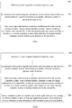
- FIG. 1 is a flowchart of a method of switching between master and standby container systems according to an example of the present disclosure.
- the method may be applied to a first container system deployed in a physical network device, and a shared file is created in the physical network device.
- the first container system functions as a master container system running in the physical network device, and the running environment of the physical network device is single machine ISSU.
- the method of switching between master and standby container systems may include the following blocks.
- the first container system receives a system upgrade instruction input by a user.
- the first container system runs in the physical network device.
- the user may input the system upgrade instruction through a command line and so on.
- the first container system in response to the system upgrade instruction, sends container system data to a second container system which functions as a standby container system in the physical network device.
- the first container system may copy and compress the container system data of the first container system (for example, various data of application processes) and send the copied and compressed container system data to the second container system in response to the system upgrade instruction.
- the second container system may back up the above system data and send a data backup completion notification to the first container system after completing the backup operation.
- the second container system is a container system that is created previously in the physical network device, the second container system runs in a background of the physical network device, and a user has no perception for the second container system.
- the physical network device currently runs the first container system. After the first container system receives the system upgrade instruction, the physical network device creates the second container system. The first container system establishes communication connection with the second container system and sends the container system data to the created second container system.
- the first container system After receiving a data backup completion notification from the second container system, the first container system writes a master/standby container system switching notification into the shared file, so that the second container system switches to function as the master container system when detecting the master/standby container system switching notification in the shared file.
- the first container system After receiving the above data backup completion notification, the first container system writes the master/standby container system switching notification into the shared file. After detecting the master/standby container system switching notification in the shared file, the second container system switches to function as the master container system, thereby completing switching between master and standby container systems.
- the example of the present disclosure may also be applied to an environment of ISSU with multiple container systems (one master container system and multiple standby container systems).
- the master container system when upgrading, may designate one standby container system to function as the master container system, or the multiple standby container systems may elect one master container system from the multiple standby container systems by performing an election operation.
- the master container system may designate one standby container system in the multiple standby container systems to function as a to-be-switched standby container system and write the master/standby container system switching notification into the shared file, where the master/standby container system switching notification includes identifier information of the to-be-switched standby container system.
- the multiple standby container systems monitor the shared file.
- the standby container system represented by the identifier information of the to-be-switched standby container system included in the master/standby container system switching notification responds to the master/standby container system switching notification and switches to function as the master container system.
- the master container system writes the master/standby container system switching notification into the shared file.
- the multiple standby container systems monitor the shared file.
- the multiple standby container systems perform an election operation. For example, elect one standby container system keeping alive for long time and/or having a small MAC address to function as the master container system.
- the elected standby container system switches to function as the master container system in response to the master/standby container system switching notification.
- the first container system sends the container system data to the second container system after receiving the system upgrade instruction input by a user, and writes the master/standby container system switching notification into the shared file after receiving the data backup completion notification from the second container system, so that the second standby container system monitoring the shared file may switch to function as the master container system after detecting the master/standby container system switching notification.
- the method of switching between master and standby container systems provided in the example of the present disclosure will not affect currently running application processes.
- the second container system since the second container system monitors the shared file in real time, the second container system may switches to function as the master container system when the first container system writes the master/standby container system switching notification into the shared file, thereby ensuring that the master and standby container systems can switch in real time. Further, in the process of monitoring a change of the shared file by the second container system, when the shared file does not change, CPU resources will not be consumed, and thus the resource waste can be reduced.
- a third-party system since a third-party system is not required for performing master and standby arbitration, the costs of switching between the master and standby container systems can be saved.
- the first container system may send a container system exit notification to each application process running in the first container system, so that each application process may stop running in the first container system according to the container system exit notification. In this way, resources occupied by each application process in the first container system will be released.
- the method of switching between master and standby container systems shown in FIG. 2 includes the following blocks.
- a first container system receives a system upgrade instruction input by a user.
- the first container system in response to the system upgrade instruction, sends container system data to a second container system functioning as a standby container system in a physical network device.
- the first container system After receiving a data backup completion notification from the second container system, the first container system writes a master/standby container system switching notification into a shared file, so that the second container system switches to function as the master container system when detecting the master/standby container system switching notification in the shared file.
- blocks 201-203 in the example of the present disclosure are similar to blocks 101-103 in the foregoing method example, and will not be described again herein.
- the first container system sends a container system exit notification to each application process running in the first container system, so that each application process stops running in the first container system according to the container system exit notification.
- the first container system sends the container system exit notification to each application process running in the first container system, for example, the first container system sends the container system exit notification in a broadcast manner. After receiving the container system exit notification, each application process stops running based on the container system exit notification to release resources occupied by the first container system.
- the above method may also include the following block.
- a network disconnection instruction is sent to a system driver of the first container system so that the system driver no longer sends or receives data.
- the system driver may be a mainboard driver of the first container system.
- the first container system sends the network disconnection instruction to the system driver of the first container system and the network disconnection instruction instructs the system driver to no longer send data and no longer receive data.
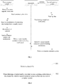
- FIG. 3 is a three-party interaction schematic diagram of a method of switching between master and standby container systems according to an example of the present disclosure.
- a physical network device includes a first container system, a second container system and a shared file, where the first container system functions as a master container system, the second container system functions as a standby container system, and the second container system monitors the shared file.
- the first container system After receiving the system upgrade instruction, the first container system copies and compresses container system data and sends the container system data to the second container system. After receiving the container system data, the second container system backs up the container system data and sends a data backup completion notification to the first container system after completing backup operation for the container system data. After receiving the data backup completion notification, the first container system writes a master/standby container system switching notification into the shared file and sends a network disconnection instruction to a system driver and sends a container system exit notification to each application process.
- the second container system After detecting the master/standby container system switching notification in the shared file, the second container system switches to function as the master container system.
- FIG. 4 is a flowchart of a method of switching between master and standby container systems according to still another example of the present disclosure.
- the method may be applied to a second container system deployed in a physical network device, and a shared file is created in the physical network device.
- the second container system functions as a standby container system running in the physical network device.
- the method of switching between master and standby container systems may include the following blocks.
- the second container system monitors the shared file.
- the second container system starts to monitor the shared file.
- the second container system switches to function as a master container system.
- the master/standby container system switching notification is written into the shared file by a first container system when the first container system functions as a master container system corresponding to the standby container system and determines that the second container system completing data backup.
- the first container system When performing switching between master and standby container systems, the first container system writes the master/standby container system switching notification into the shared file.
- the second container system When detecting a change of the shared file, such as the master/standby container system switching notification in the shared file, the second container system switches to function as the master container system.
- the above method also includes: a master-container-system broadcast notification is sent, where the master-container-system broadcast notification comprises address information of the second container system, so that a process receiving the master-container-system broadcast notification sends a data packet to the second container system according to the address information of the second container system.
- the second container system After switching to function as the master container system, the second container system sends the master-container-system broadcast notification to each application process running in the second container system, where the master-container-system broadcast notification includes the address information of the second container system.
- each process receiving the master-container-system broadcast notification may send a data packet to the second container system according to the address information of the second container system.
- the first container system when performing switching between master and standby container systems, writes the master/standby container system switching notification into the shared file; and after detecting the master/standby container system switching notification in the shared file, the second container system switches to function as the master container system.
- the second container system since the second container system monitors the shared file in real time, the second container system can switch to function as the master container system when the first container system writes the master/standby container system switching notification into the shared file, thereby ensuring that the master and standby container systems can switch in real time. Further, in the process of monitoring a change of the shared file by the second container system, when the shared file does not change, CPU resources will not be consumed, and thus the resource waste can be reduced. In the second aspect, since a third-party system is not required for performing master and standby arbitration, the costs of switching between the master and standby container systems can be saved.
- the second container system when the second container system functions as the standby container system, the second container system receives container system data from the first container system and backs up the container system data, so that the second container system runs the same application processes as application processes running in the first container system, and sends a data backup completion notification to the first container system after completing the data backup.
- the present disclosure will be described below by referring to a flowchart of a method of switching between master and standby container systems as shown in FIG. 5 .
- the method of switching between master and standby container systems shown in FIG. 5 may include the following blocks.
- a second container system monitors a shared file.
- block 501 is similar to block 401 in the foregoing method example, and will not be described again herein.
- the second container system receives container system data from a first container system functioning as a master container system.
- the first container system After receiving a system upgrade instruction input by a user, the first container system copies and compresses the container system data and sends the container system data to the second container system.
- the second container system sends a data backup completion notification to the first container system, so that the first container system writes a master/standby container system switching notification into the shared file according to the data backup completion notification.
- the second container system After receiving the container system data, the second container system backs up the container system data and sends the data backup completion notification to the first container system after completing backup operation for the container system data, so that the first container system writes the master/standby container system switching notification into the shared file after receiving the data backup completion notification.
- the second container system switches to function as the master container system.
- the master/standby container system switching notification is written by the first container system into the shared file.
- block 504 is similar to block 402 in the foregoing method example, and will not be described again herein.
- FIG. 6 is a structural block diagram of an apparatus for switching between master and standby container systems according to an example of the present disclosure.
- the apparatus may be applied to a first container system deployed in a physical network device, and a shared file is created in the physical network device.
- the first container system functions as a master container system running in the physical network device.
- the apparatus for switching between master and standby container systems may include the following modules.
- a receiving module 601 configured to receive a system upgrade instruction input by a user.
- a sending module configured to send container system data to a second container system functioning as a standby container system in the physical network device in response to the system upgrade instruction.
- a notifying module 603, configured to write a master/standby container system switching notification into the shared file after receiving a data backup completion notification from the second container system, so that the second container system switches to function as the master container system when detecting the master/standby container system switching notification in the shared file.
- the first container system sends the container system data to the second container system after receiving the system upgrade instruction input by the user, and writes the master/standby container system switching notification into the shared file after receiving the data backup completion notification from the second container system, so that the second container system monitoring the shared file switches to function as the master container system after detecting the master/standby container system switching notification in the shared file.
- the apparatus for switching between master and standby container systems provided in the example of the present disclosure will not affect currently running application processes.
- the second container system since the second container system monitors the shared file in real time, the second container system may switches to function as the master container system when the first container system writes the master/standby container system switching notification into the shared file, thereby ensuring that the master and standby container systems can switch in real time. Further, in the process of monitoring a change of the shared file by the second container system, when the shared file does not change, CPU resources will not be consumed, and thus the resource waste can be reduced.
- a third-party system since a third-party system is not required for performing master and standby arbitration, the costs of switching between the master and standby container systems can be saved.
- FIG. 7 is a structural block diagram of an apparatus for switching between master and standby container systems according to another example of the present disclosure.
- a receiving module 701, a sending module 702 and a notifying module 705 are similar to the receiving module 601, the sending module 602 and the notifying module 603 as described in the above example and will not be repeated herein.
- the apparatus also includes: An exiting module 704, configured to send a container system exit notification to each application process running in the first container system in response to completing writing the master/standby container system switching notification, so that each application process stops running in the first container system according to the container system exit notification.
- the apparatus also includes: a disconnecting module 703, configured to send a network disconnection instruction to a system driver of the first container system after receiving the data backup completion notification from the second container system, so that the system driver no longer sends and receives data.
- a disconnecting module 703 configured to send a network disconnection instruction to a system driver of the first container system after receiving the data backup completion notification from the second container system, so that the system driver no longer sends and receives data.
- FIG. 8 is a structural block diagram of an apparatus for switching between master and standby container systems according to still another example of the present disclosure.
- the apparatus may be applied to a second container system deployed in a physical network device, and a shared file is created in the physical network device.
- the second container system functions as a standby container system running in the physical network device.
- the above apparatus for switching between master and standby container systems includes the following modules.
- a switching module 802 configured to switch the second container system to function as a master container system when detecting a master/standby container system switching notification in the shared file.
- the master/standby container system switching notification is written into the shared file by a first container system when the first container system functions as the master container system corresponding to the standby container system and determines that the second container system completes data backup.
- the first container system writes the master/standby container system switching notification into the shared file when performing switching between master and standby container systems, and the second container system switches to function as the master container system after detecting the master/standby container system switching notification in the shared file.
- the second container system since the second container system monitors the shared file in real time, the second container system switches to function as the master container system when the first container system writes the master/standby container system switching notification into the shared file, thereby ensuring that the master and standby container systems switches in real time. Further, in the process of monitoring a change of the shared file by the second container system, when the shared file does not change, CPU resources will not be consumed, and thus the resource waste can be reduced. In the second aspect, since a third-party system is not required for performing master and standby arbitration, the costs of switching between the master and standby container systems can be saved.
- FIG. 9 is a structural block diagram of an apparatus for switching between master and standby container systems according to yet another example of the present disclosure.
- a monitoring module 903 and a switching module 904 are similar to the monitoring module 801 and the switching module 802 as described in the above example and will not be repeated herein.
- the apparatus may also include:
- the apparatus may also include: a second sending module 905, configured to send a master-container-system broadcast notification, where the master-container-system broadcast notification comprises address information of the second container system, so that a process receiving the master-container-system broadcast notification sends a data packet to the second container system according to the address information of the second container system.
- a second sending module 905 configured to send a master-container-system broadcast notification, where the master-container-system broadcast notification comprises address information of the second container system, so that a process receiving the master-container-system broadcast notification sends a data packet to the second container system according to the address information of the second container system.
- FIG. 10 is a hardware structural block diagram of an apparatus for switching between master and standby container systems according to an example of the present disclosure.
- the apparatus may be implemented through a network device.
- the apparatus 1300 may include a processor 1301 and a machine readable storage medium 1302 storing machine executable instructions.
- the processor 1301 and the machine readable storage medium 1302 may communicate via a system bus 1303. Also, by reading the machine executable instructions stored in the machine readable storage medium 1302 and corresponding to the logic of switching between master and standby container systems, the processor 1301 is caused to perform the above methods of switching between master and standby container systems.
- the machine readable storage medium 1302 mentioned herein may be any of electronic, magnetic, optical or other physical storage devices and may contain or store information such as executable instructions, data, and so on.
- the machine readable storage medium may be a Radom Access Memory (RAM), a volatile memory, a nonvolatile memory, a flash memory, a storage drive (e.g. hard disk drive), a solid state hard disk, any type of storage disk (e.g., compact disk, Digital Video Disk (DVD)), or a similar storage medium, or a combination thereof.
Landscapes
- Engineering & Computer Science (AREA)
- Theoretical Computer Science (AREA)
- Software Systems (AREA)
- General Engineering & Computer Science (AREA)
- Physics & Mathematics (AREA)
- General Physics & Mathematics (AREA)
- Signal Processing (AREA)
- Computer Networks & Wireless Communication (AREA)
- Computer Security & Cryptography (AREA)
- Quality & Reliability (AREA)
- Computing Systems (AREA)
- Mathematical Physics (AREA)
- Hardware Redundancy (AREA)
- Information Retrieval, Db Structures And Fs Structures Therefor (AREA)
- Stored Programmes (AREA)
- Computer Hardware Design (AREA)
Abstract
Description
- In-Service Software Upgrade (ISSU) is a manner by which software on a device can be upgraded with high reliability. Single machine ISSU with dual systems refers to a physical device having two containers, each of which runs one container system respectively, and the two container systems are master container system and standby container system for each other. By applying a virtual technology for isolation, the master container system, the standby container system, and application processes running on the master container system or the standby system can be isolated. The standby container system may switch to function as a master container system when the master container system stops running so that the service upgrade can be ensured.
- In a first related art, the master container system and the standby container system may complete switching between the master and standby container systems by sending heartbeats to each other. However, in a case of a large time interval of sending the heartbeats, there may be a problem that the master and standby container systems may not switch in time. In a case of sending heartbeats intensively, more resources of Central Processing Unit (CPU) will be occupied, resulting in a problem of resource wastes.
- In a second related art, a third-party system (for example, a physical device, or a physical system) may be run in the physical device to perform master and standby arbitration. The third-party system may monitor the master and standby container systems, and notify the standby container system to switch to function as a master system when the master container system does not run any longer. However, costs of switching between the master and standby container systems are increased by using the third-party system to perform the master and standby arbitration.
- The accompanying drawings, which are incorporated in and constitute a part of this present specification, illustrate illustrative examples, features and aspects of the present disclosure and, together with the description, serve to explain the principles of the present disclosure.
-
FIG. 1 is a flowchart of a method of switching between master and standby container systems according to an example of the present disclosure. -
FIG. 2 is a flowchart of a method of switching between master and standby container systems according to another example of the present disclosure. -
FIG. 3 is a three-party interaction schematic diagram of a method of switching between master and standby container systems according to an example of the present disclosure. -
FIG. 4 is a flowchart of a method of switching between master and standby container systems according to still another example of the present disclosure. -
FIG. 5 is a flowchart of a method of switching between master and standby container systems according to yet another example of the present disclosure. -
FIG. 6 is a structural block diagram of an apparatus for switching between master and standby container systems according to an example of the present disclosure. -
FIG. 7 is a structural block diagram of an apparatus for switching between master and standby container systems according to another example of the present disclosure. -
FIG. 8 is a structural block diagram of an apparatus for switching between master and standby container systems according to still another example of the present disclosure. -
FIG. 9 is a structural block diagram of an apparatus for switching between master and standby container systems according to yet another example of the present disclosure. -
FIG. 10 is a hardware structural block diagram of an apparatus for switching between master and standby container systems according to an example of the present disclosure. - Various illustrative examples, features and aspects of the present disclosure will be described in detail below with reference to the drawings. Like numerals in the drawings refer to elements with like or similar functions. Although various aspects of the examples are illustrated in the drawings, the drawings are not necessarily drawn pro rata unless otherwise indicated.
- The term "illustrative" herein is intended as "serving as an example, an embodiment or exemplary". Any example described as "illustrative" herein is not necessarily interpreted as better than or superior to other examples.
- In addition, to better describe the present disclosure, numerous specific details are given in the following specific examples. Those skilled in the art should understand that the present disclosure may be implemented without some specific details. In some instances, methods, approaches, elements and circuits well known to those skilled in the art are not described in detail so as to highlight the gist of the present disclosure.
- At present, isolation technology includes virtual machine isolation, process isolation and container isolation.
- The virtual machine isolation may completely simulate physical components such as a CPU and a memory in a network device by running a complete operating system and therefore the virtual machine isolation is a heavy-weight virtual technology resulting in slow startup and shutdown and large consumption of hardware resources (such as a memory, a hard disk and a CPU).
- The process isolation, as a light isolation, does not perform any physical simulation. In a default case, memories cannot be accessed each other, but network and magnetic disk may be accessed each other. There is no cost to using the process isolation, but the isolation effect is not satisfied.
- With coming of containers, a gap between the virtual machine isolation and the process isolation can be filled. The container does not simulate physical devices such as a CPU and a memory, nor have its own kernel. The container usually runs only one group of user mode programs and shares one kernel with a host machine. The container encapsulates a running environment, a cache environment, a database environment and so on required for application to support programs running in a simple manner. One container may be equivalent to a separate and complete software system, for example, a comware software system.
- The container technology does not involve hardware and kernel, and only runs required programs, that is, does not include those programs involved in the operating system. Thus, startup is usually very quick. Further, only required programs and dependent libraries may be run and therefore a smaller space may be taken compared with a complete virtual machine.
- To solve the problem that the master and standby container systems may not switch in time or switching between the master and standby container systems may easily cause resource wastes in the first related art, and the problem that the cost of switching between the master and standby container systems is high in the second related art, a shared file is created in a physical network device and the standby container system monitors the shared file in examples of the present disclosure. When performing switching between master and standby containers, the master container system may write a master/standby container system switching notification into the shared file. When the standby container system detects the above master/standby container system switching notification in the shared file, the standby container system switches to function as a master container system, so as to ensure timeliness of switching between the master and standby container systems without wasting resources and lower the cost of switching between the master and standby container systems.
- Examples of the present disclosure may not only be applied to an environment of single machine ISSU with dual containers, but also be applied to an environment of single machine ISSU with multiple containers (one master container system and multiple standby container systems). In the environment of single machine ISSU, at least two container systems (a master container system and a standby container system) exist in the physical network device and perform switching between the master and standby container systems. The examples of the present disclosure will be described with an application in the environment of single machine ISSU as an example.
-
FIG. 1 is a flowchart of a method of switching between master and standby container systems according to an example of the present disclosure. The method may be applied to a first container system deployed in a physical network device, and a shared file is created in the physical network device. The first container system functions as a master container system running in the physical network device, and the running environment of the physical network device is single machine ISSU. As shown inFIG. 1 , the method of switching between master and standby container systems may include the following blocks. - At
block 101, the first container system receives a system upgrade instruction input by a user. - In an example of the present disclosure, the first container system runs in the physical network device. When the first container system needs to be upgraded, the user may input the system upgrade instruction through a command line and so on.
- At
block 102, in response to the system upgrade instruction, the first container system sends container system data to a second container system which functions as a standby container system in the physical network device. - After receiving the system upgrade instruction, the first container system may copy and compress the container system data of the first container system (for example, various data of application processes) and send the copied and compressed container system data to the second container system in response to the system upgrade instruction. After receiving the above system data, the second container system may back up the above system data and send a data backup completion notification to the first container system after completing the backup operation.
- In an example of the present disclosure, in an implementation, the second container system is a container system that is created previously in the physical network device, the second container system runs in a background of the physical network device, and a user has no perception for the second container system. In another implementation, the physical network device currently runs the first container system. After the first container system receives the system upgrade instruction, the physical network device creates the second container system. The first container system establishes communication connection with the second container system and sends the container system data to the created second container system.
- At
block 103, after receiving a data backup completion notification from the second container system, the first container system writes a master/standby container system switching notification into the shared file, so that the second container system switches to function as the master container system when detecting the master/standby container system switching notification in the shared file. - After receiving the above data backup completion notification, the first container system writes the master/standby container system switching notification into the shared file. After detecting the master/standby container system switching notification in the shared file, the second container system switches to function as the master container system, thereby completing switching between master and standby container systems.
- It is noted that the example of the present disclosure may also be applied to an environment of ISSU with multiple container systems (one master container system and multiple standby container systems). In the environment of one master container system and multiple standby container systems, when upgrading, the master container system may designate one standby container system to function as the master container system, or the multiple standby container systems may elect one master container system from the multiple standby container systems by performing an election operation.
- For example, the master container system may designate one standby container system in the multiple standby container systems to function as a to-be-switched standby container system and write the master/standby container system switching notification into the shared file, where the master/standby container system switching notification includes identifier information of the to-be-switched standby container system. The multiple standby container systems monitor the shared file. When the master/standby container system switching notification is detected, the standby container system represented by the identifier information of the to-be-switched standby container system included in the master/standby container system switching notification responds to the master/standby container system switching notification and switches to function as the master container system.
- For another example, the master container system writes the master/standby container system switching notification into the shared file. The multiple standby container systems monitor the shared file. When detecting the master/standby container system switching notification, the multiple standby container systems perform an election operation. For example, elect one standby container system keeping alive for long time and/or having a small MAC address to function as the master container system. The elected standby container system switches to function as the master container system in response to the master/standby container system switching notification.
- Therefore, according to the method of switching between master and standby container systems provided in the examples of the present disclosure, the first container system sends the container system data to the second container system after receiving the system upgrade instruction input by a user, and writes the master/standby container system switching notification into the shared file after receiving the data backup completion notification from the second container system, so that the second standby container system monitoring the shared file may switch to function as the master container system after detecting the master/standby container system switching notification.
- In this way, in the first aspect, the method of switching between master and standby container systems provided in the example of the present disclosure will not affect currently running application processes. In the second aspect, since the second container system monitors the shared file in real time, the second container system may switches to function as the master container system when the first container system writes the master/standby container system switching notification into the shared file, thereby ensuring that the master and standby container systems can switch in real time. Further, in the process of monitoring a change of the shared file by the second container system, when the shared file does not change, CPU resources will not be consumed, and thus the resource waste can be reduced. In the third aspect, since a third-party system is not required for performing master and standby arbitration, the costs of switching between the master and standby container systems can be saved.
- In another example, after writing the master/standby container system switching notification into the shared file, the first container system may send a container system exit notification to each application process running in the first container system, so that each application process may stop running in the first container system according to the container system exit notification. In this way, resources occupied by each application process in the first container system will be released. An example of the present disclosure will be described below with reference to a flowchart of a method of switching between master and standby container systems as shown in
FIG. 2 . - Specifically, the method of switching between master and standby container systems shown in
FIG. 2 includes the following blocks. - At
block 201, a first container system receives a system upgrade instruction input by a user. - At
block 202, in response to the system upgrade instruction, the first container system sends container system data to a second container system functioning as a standby container system in a physical network device. - At
block 203, after receiving a data backup completion notification from the second container system, the first container system writes a master/standby container system switching notification into a shared file, so that the second container system switches to function as the master container system when detecting the master/standby container system switching notification in the shared file. - It is noted that blocks 201-203 in the example of the present disclosure are similar to blocks 101-103 in the foregoing method example, and will not be described again herein.
- At
block 204, the first container system sends a container system exit notification to each application process running in the first container system, so that each application process stops running in the first container system according to the container system exit notification. - The first container system sends the container system exit notification to each application process running in the first container system, for example, the first container system sends the container system exit notification in a broadcast manner. After receiving the container system exit notification, each application process stops running based on the container system exit notification to release resources occupied by the first container system.
- In a possible implementation, the above method may also include the following block.
- A network disconnection instruction is sent to a system driver of the first container system so that the system driver no longer sends or receives data.
- The system driver may be a mainboard driver of the first container system. The first container system sends the network disconnection instruction to the system driver of the first container system and the network disconnection instruction instructs the system driver to no longer send data and no longer receive data.
- In this way, it is possible to avoid a problem that the first container system still synchronizes data with the second container system when an application process in the first container system does not stop running and the second container system is already switched as the master container system.
- To make those skilled in the art better understand examples of the present disclosure, the present disclosure will be described below with specific examples.
-
FIG. 3 is a three-party interaction schematic diagram of a method of switching between master and standby container systems according to an example of the present disclosure. As shown inFIG. 3 , a physical network device includes a first container system, a second container system and a shared file, where the first container system functions as a master container system, the second container system functions as a standby container system, and the second container system monitors the shared file. - After receiving the system upgrade instruction, the first container system copies and compresses container system data and sends the container system data to the second container system. After receiving the container system data, the second container system backs up the container system data and sends a data backup completion notification to the first container system after completing backup operation for the container system data. After receiving the data backup completion notification, the first container system writes a master/standby container system switching notification into the shared file and sends a network disconnection instruction to a system driver and sends a container system exit notification to each application process.
- After detecting the master/standby container system switching notification in the shared file, the second container system switches to function as the master container system.
-
FIG. 4 is a flowchart of a method of switching between master and standby container systems according to still another example of the present disclosure. The method may be applied to a second container system deployed in a physical network device, and a shared file is created in the physical network device. The second container system functions as a standby container system running in the physical network device. As shown inFIG. 4 , the method of switching between master and standby container systems may include the following blocks. - At
block 401, the second container system monitors the shared file. - When starting to run, the second container system starts to monitor the shared file.
- At
block 402, when detecting a master/standby container system switching notification in the shared file, the second container system switches to function as a master container system. - The master/standby container system switching notification is written into the shared file by a first container system when the first container system functions as a master container system corresponding to the standby container system and determines that the second container system completing data backup.
- When performing switching between master and standby container systems, the first container system writes the master/standby container system switching notification into the shared file. When detecting a change of the shared file, such as the master/standby container system switching notification in the shared file, the second container system switches to function as the master container system.
- In a possible implementation, the above method also includes: a master-container-system broadcast notification is sent, where the master-container-system broadcast notification comprises address information of the second container system, so that a process receiving the master-container-system broadcast notification sends a data packet to the second container system according to the address information of the second container system.
- After switching to function as the master container system, the second container system sends the master-container-system broadcast notification to each application process running in the second container system, where the master-container-system broadcast notification includes the address information of the second container system. When sending a data packet to the master container system, each process receiving the master-container-system broadcast notification may send a data packet to the second container system according to the address information of the second container system.
- Thus, according to the method of switching between master and standby container systems provided in the example of the present disclosure, when performing switching between master and standby container systems, the first container system writes the master/standby container system switching notification into the shared file; and after detecting the master/standby container system switching notification in the shared file, the second container system switches to function as the master container system.
- In this way, in the first aspect, since the second container system monitors the shared file in real time, the second container system can switch to function as the master container system when the first container system writes the master/standby container system switching notification into the shared file, thereby ensuring that the master and standby container systems can switch in real time. Further, in the process of monitoring a change of the shared file by the second container system, when the shared file does not change, CPU resources will not be consumed, and thus the resource waste can be reduced. In the second aspect, since a third-party system is not required for performing master and standby arbitration, the costs of switching between the master and standby container systems can be saved.
- In another example, when the second container system functions as the standby container system, the second container system receives container system data from the first container system and backs up the container system data, so that the second container system runs the same application processes as application processes running in the first container system, and sends a data backup completion notification to the first container system after completing the data backup. The present disclosure will be described below by referring to a flowchart of a method of switching between master and standby container systems as shown in
FIG. 5 . - Specifically, the method of switching between master and standby container systems shown in
FIG. 5 may include the following blocks. - At
block 501, a second container system monitors a shared file. - In the example of the present disclosure, block 501 is similar to block 401 in the foregoing method example, and will not be described again herein.
- At
block 502, the second container system receives container system data from a first container system functioning as a master container system. - After receiving a system upgrade instruction input by a user, the first container system copies and compresses the container system data and sends the container system data to the second container system.
- At
block 503, after completing backup operation for the container system data, the second container system sends a data backup completion notification to the first container system, so that the first container system writes a master/standby container system switching notification into the shared file according to the data backup completion notification. - After receiving the container system data, the second container system backs up the container system data and sends the data backup completion notification to the first container system after completing backup operation for the container system data, so that the first container system writes the master/standby container system switching notification into the shared file after receiving the data backup completion notification.
- At
block 504, when detecting the master/standby container system switching notification in the shared file, the second container system switches to function as the master container system. - The master/standby container system switching notification is written by the first container system into the shared file. In the example, block 504 is similar to block 402 in the foregoing method example, and will not be described again herein.
- In this way, according to the method of switching between master and standby container systems provided in the present disclosure, it can be ensured that application processes running in the second container system are same as application processes running in the first container system, and it can be ensured that the application processes currently running will not be affected during a process of master and standby container system switchover.
-
FIG. 6 is a structural block diagram of an apparatus for switching between master and standby container systems according to an example of the present disclosure. The apparatus may be applied to a first container system deployed in a physical network device, and a shared file is created in the physical network device. The first container system functions as a master container system running in the physical network device. As shown inFIG. 6 , the apparatus for switching between master and standby container systems may include the following modules. - A receiving
module 601, configured to receive a system upgrade instruction input by a user. - A sending module, configured to send container system data to a second container system functioning as a standby container system in the physical network device in response to the system upgrade instruction.
- A notifying
module 603, configured to write a master/standby container system switching notification into the shared file after receiving a data backup completion notification from the second container system, so that the second container system switches to function as the master container system when detecting the master/standby container system switching notification in the shared file. - Thus, with the apparatus for switching between master and standby container systems provided in the example of the present disclosure, the first container system sends the container system data to the second container system after receiving the system upgrade instruction input by the user, and writes the master/standby container system switching notification into the shared file after receiving the data backup completion notification from the second container system, so that the second container system monitoring the shared file switches to function as the master container system after detecting the master/standby container system switching notification in the shared file.
- In this way, in the first aspect, the apparatus for switching between master and standby container systems provided in the example of the present disclosure will not affect currently running application processes. In the second aspect, since the second container system monitors the shared file in real time, the second container system may switches to function as the master container system when the first container system writes the master/standby container system switching notification into the shared file, thereby ensuring that the master and standby container systems can switch in real time. Further, in the process of monitoring a change of the shared file by the second container system, when the shared file does not change, CPU resources will not be consumed, and thus the resource waste can be reduced. In the third aspect, since a third-party system is not required for performing master and standby arbitration, the costs of switching between the master and standby container systems can be saved.
-
FIG. 7 is a structural block diagram of an apparatus for switching between master and standby container systems according to another example of the present disclosure. A receivingmodule 701, a sendingmodule 702 and a notifyingmodule 705 are similar to the receivingmodule 601, the sendingmodule 602 and the notifyingmodule 603 as described in the above example and will not be repeated herein. - In a possible implementation, as shown in
FIG. 7 , the apparatus also includes:
An exitingmodule 704, configured to send a container system exit notification to each application process running in the first container system in response to completing writing the master/standby container system switching notification, so that each application process stops running in the first container system according to the container system exit notification. - In a possible implementation, as shown in
FIG. 7 , the apparatus also includes:
adisconnecting module 703, configured to send a network disconnection instruction to a system driver of the first container system after receiving the data backup completion notification from the second container system, so that the system driver no longer sends and receives data. -
FIG. 8 is a structural block diagram of an apparatus for switching between master and standby container systems according to still another example of the present disclosure. The apparatus may be applied to a second container system deployed in a physical network device, and a shared file is created in the physical network device. The second container system functions as a standby container system running in the physical network device. As shown inFIG. 8 , the above apparatus for switching between master and standby container systems includes the following modules. - A
monitoring module 801, configured to monitor the shared file. - A
switching module 802, configured to switch the second container system to function as a master container system when detecting a master/standby container system switching notification in the shared file. - The master/standby container system switching notification is written into the shared file by a first container system when the first container system functions as the master container system corresponding to the standby container system and determines that the second container system completes data backup.
- Thus, with the apparatus for switching between master and standby container systems provided in the example of the present disclosure, the first container system writes the master/standby container system switching notification into the shared file when performing switching between master and standby container systems, and the second container system switches to function as the master container system after detecting the master/standby container system switching notification in the shared file.
- In this way, in the first aspect, since the second container system monitors the shared file in real time, the second container system switches to function as the master container system when the first container system writes the master/standby container system switching notification into the shared file, thereby ensuring that the master and standby container systems switches in real time. Further, in the process of monitoring a change of the shared file by the second container system, when the shared file does not change, CPU resources will not be consumed, and thus the resource waste can be reduced. In the second aspect, since a third-party system is not required for performing master and standby arbitration, the costs of switching between the master and standby container systems can be saved.
-
FIG. 9 is a structural block diagram of an apparatus for switching between master and standby container systems according to yet another example of the present disclosure. Amonitoring module 903 and aswitching module 904 are similar to themonitoring module 801 and theswitching module 802 as described in the above example and will not be repeated herein. - In a possible implementation, as shown in
FIG. 9 , the apparatus may also include: - a
receiving module 901, configured to receive container system data from the first container system; and - a
first sending module 902, configured to send a data backup completion notification to the first container system after completing backup operation for the container system data, so that the first container system writes the master/standby container system switching notification into the shared file according to the data backup completion notification. - In a possible implementation, as shown in
FIG. 9 , the apparatus may also include:
asecond sending module 905, configured to send a master-container-system broadcast notification, where the master-container-system broadcast notification comprises address information of the second container system, so that a process receiving the master-container-system broadcast notification sends a data packet to the second container system according to the address information of the second container system. -
FIG. 10 is a hardware structural block diagram of an apparatus for switching between master and standby container systems according to an example of the present disclosure. In a practical application, the apparatus may be implemented through a network device. As shown inFIG. 10 , the apparatus 1300 may include aprocessor 1301 and a machinereadable storage medium 1302 storing machine executable instructions. Theprocessor 1301 and the machinereadable storage medium 1302 may communicate via a system bus 1303. Also, by reading the machine executable instructions stored in the machinereadable storage medium 1302 and corresponding to the logic of switching between master and standby container systems, theprocessor 1301 is caused to perform the above methods of switching between master and standby container systems. - The machine
readable storage medium 1302 mentioned herein may be any of electronic, magnetic, optical or other physical storage devices and may contain or store information such as executable instructions, data, and so on. For example, the machine readable storage medium may be a Radom Access Memory (RAM), a volatile memory, a nonvolatile memory, a flash memory, a storage drive (e.g. hard disk drive), a solid state hard disk, any type of storage disk (e.g., compact disk, Digital Video Disk (DVD)), or a similar storage medium, or a combination thereof. - The examples of the present disclosure described as above are illustrative and non-exhaustive, and are not limited to these examples disclosed herein. It is apparent that many changes and modifications may be made by those skilled in the art without departing from the scope and spirit of the examples of the present disclosure. The selection of terms used herein is intended to best explain the principle and the practical applications of different examples or technical improvements of technologies in market, or to allow other persons skilled in the art to understand the examples of the present disclosure.
Claims (12)
- A method of switching between master and standby container systems, the method being applied to a first container system deployed in a physical network device and functioning as a master container system, a shared file being created in the physical network device, and the method comprising:receiving a system upgrade instruction input by a user;in response to the system upgrade instruction, sending container system data to a second container system functioning as a standby container system corresponding to the master container system in the physical network device; andupon receiving a data backup completion notification from the second container system, writing a master/standby container system switching notification into the shared file, so that the second container system switches to function as a new master container system when detecting the master/standby container system switching notification in the shared file.
- The method according to claim 1, further comprising
in response to completing writing the master/standby container system switching notification, sending a container system exit notification to each application process running in the first container system, so that each application process stops running in the first container system according to the container system exit notification. - The method according to claim 1, further comprising:
upon receiving the data backup completion notification from the second container system, sending a network disconnection instruction to a system driver of the first container system, so that the system driver no longer sends and receives data. - A method of switching between master and standby container systems, the method being applied to a second container system deployed in a physical network device and functioning as a standby container system, a shared file being created in the physical network device, and the method comprising:monitoring the shared file; andswitching the second container system to function as a master container system upon detecting a master/standby container system switching notification in the shared file;wherein, the master/standby container system switching notification is written into the shared file by a first container system when the first container system functions as the master container system corresponding to the standby container system and determines that the second container system completes data backup.
- The method according to claim 4, further comprising:receiving container system data from the first container system; andupon completing backup operation for the container system data, sending a data backup completion notification to the first container system, so that the first container system writes the master/standby container system switching notification into the shared file according to the data backup completion notification.
- The method according to claim 4, further comprising:
sending a master-container-system broadcast notification, wherein the master-container-system broadcast notification comprises address information of the second container system, so that a process receiving the master-container-system broadcast notification sends a data packet to the second container system according to the address information of the second container system. - An apparatus for switching between master and standby container systems, the apparatus being applied to a first container system deployed in a physical network device and functioning as a master container system, a shared file being created in the physical network device, and the apparatus comprising:a receiving module, configured to receive a system upgrade instruction input by a user;a sending module, configured to send container system data to a second container system functioning as a standby container system corresponding to a new master container system in the physical network device in response to the system upgrade instruction; anda notifying module, configured to write a master/standby container system switching notification into the shared file upon receiving a data backup completion notification from the second container system, so that the second container system switches to function as the master container system when detecting the master/standby container system switching notification in the shared file.
- The apparatus according to claim 7, further comprising:
an exiting module, configured to send a container system exit notification to each application process running in the first container system in response to completing writing the master/standby container system switching notification, so that each application process stops running in the first container system according to the container system exit notification. - The apparatus according to claim 7, further comprising:
a disconnecting module, configured to send a network disconnection instruction to a system driver of the first container system upon receiving the data backup completion notification from the second container system, so that the system driver no longer sends and receives data. - An apparatus for switching between master and standby container systems, the apparatus being applied to a second container system deployed in a physical network device and functioning as a standby container system, a shared file being created in the physical network device, and the apparatus comprising:a monitoring module, configured to monitor the shared file; anda switching module, configured to switch the second container system to function as a master container system upon detecting a master/standby container system switching notification in the shared file;wherein, the master/standby container system switching notification is written into the shared file by a first container system when the first container system functions as the master container system corresponding to the standby container system and determines that the second container system completes data backup.
- The apparatus according to claim 10, further comprising:a receiving module, configured to receive container system data from the first container system;a first sending module, configured to send a data backup completion notification to the first container system upon completing backup operation for the container system data, so that the first container system writes the master/standby container system switching notification into the shared file according to the data backup completion notification.
- The apparatus according to claim 10, further comprising:
a second sending module, configured to send a master-container-system broadcast notification, wherein the master-container-system broadcast notification comprises address information of the second container system, so that a process receiving the master-container-system broadcast notification sends a data packet to the second container system according to the address information of the second container system.
Applications Claiming Priority (2)
| Application Number | Priority Date | Filing Date | Title |
|---|---|---|---|
| CN201810697116.3A CN108880898B (en) | 2018-06-29 | 2018-06-29 | Main and standby container system switching method and device |
| PCT/CN2019/092019 WO2020001354A1 (en) | 2018-06-29 | 2019-06-20 | Master/standby container system switch |
Publications (3)
| Publication Number | Publication Date |
|---|---|
| EP3761564A1 true EP3761564A1 (en) | 2021-01-06 |
| EP3761564A4 EP3761564A4 (en) | 2021-05-12 |
| EP3761564B1 EP3761564B1 (en) | 2024-05-15 |
Family
ID=64297117
Family Applications (1)
| Application Number | Title | Priority Date | Filing Date |
|---|---|---|---|
| EP19826514.2A Active EP3761564B1 (en) | 2018-06-29 | 2019-06-20 | Master/standby container system switch |
Country Status (5)
| Country | Link |
|---|---|
| US (1) | US12099861B2 (en) |
| EP (1) | EP3761564B1 (en) |
| JP (1) | JP7116802B2 (en) |
| CN (1) | CN108880898B (en) |
| WO (1) | WO2020001354A1 (en) |
Cited By (1)
| Publication number | Priority date | Publication date | Assignee | Title |
|---|---|---|---|---|
| US11880676B1 (en) | 2022-09-27 | 2024-01-23 | Rockwell Automation Technologies, Inc. | Containerized modeling of device updates or modifications via digital twins |
Families Citing this family (7)
| Publication number | Priority date | Publication date | Assignee | Title |
|---|---|---|---|---|
| CN108880898B (en) * | 2018-06-29 | 2020-09-08 | 新华三技术有限公司 | Main and standby container system switching method and device |
| CN112199240B (en) * | 2019-07-08 | 2024-01-30 | 华为云计算技术有限公司 | Method for switching nodes during node failure and related equipment |
| CN111045708B (en) * | 2019-12-20 | 2022-03-11 | 新华三大数据技术有限公司 | Software upgrading method, electronic device and computer readable storage medium |
| CN111443927A (en) * | 2020-02-25 | 2020-07-24 | 厦门亿联网络技术股份有限公司 | Method and system for clone upgrading between DECT roaming system devices |
| CN114529977B (en) * | 2020-11-02 | 2025-03-25 | 青岛海尔多媒体有限公司 | Gesture control method and device for smart device, and smart device |
| CN113300894A (en) * | 2021-06-03 | 2021-08-24 | 北京飞讯数码科技有限公司 | Equipment hot switching method, electronic equipment and storage medium |
| CN119861946B (en) * | 2024-12-25 | 2025-11-25 | 新华三技术有限公司 | A method and apparatus for sending and receiving messages in a standalone ISSU |
Family Cites Families (43)
| Publication number | Priority date | Publication date | Assignee | Title |
|---|---|---|---|---|
| JPH10293697A (en) | 1997-04-18 | 1998-11-04 | Hitachi Ltd | Redundant computer system |
| US7885180B2 (en) * | 2006-12-15 | 2011-02-08 | Check Point Software Technologies Inc. | Address resolution request mirroring |
| US9325790B1 (en) * | 2009-02-17 | 2016-04-26 | Netapp, Inc. | Servicing of network software components of nodes of a cluster storage system |
| US20110113426A1 (en) * | 2009-11-09 | 2011-05-12 | Hsiang-Tsung Kung | Apparatuses for switching the running of a virtual machine between multiple computer devices belonging to the same computer platform and the associated switching methods |
| JP5573649B2 (en) * | 2010-12-17 | 2014-08-20 | 富士通株式会社 | Information processing device |
| US8793684B2 (en) * | 2011-03-16 | 2014-07-29 | International Business Machines Corporation | Optimized deployment and replication of virtual machines |
| US8767737B2 (en) * | 2011-11-30 | 2014-07-01 | Industrial Technology Research Institute | Data center network system and packet forwarding method thereof |
| CN103188099B (en) * | 2011-12-30 | 2016-03-30 | 中国移动通信集团上海有限公司 | A kind of backup method of multi-application system, Apparatus and system |
| CN102662751B (en) * | 2012-03-30 | 2016-05-11 | 浪潮电子信息产业股份有限公司 | A kind of method improving based on thermophoresis dummy machine system availability |
| JP5858882B2 (en) * | 2012-08-01 | 2016-02-10 | アラクサラネットワークス株式会社 | Relay device, relay system, and method for changing power state of relay device |
| US9971616B2 (en) * | 2013-02-26 | 2018-05-15 | Red Hat Israel, Ltd. | Virtual machine suspension |
| WO2014166065A1 (en) * | 2013-04-09 | 2014-10-16 | 华为技术有限公司 | Method and device for protecting service reliability, and network virtualization system |
| JP6053637B2 (en) * | 2013-08-07 | 2016-12-27 | 日本電信電話株式会社 | Method for upgrading virtual host and network device |
| US9952885B2 (en) * | 2013-08-14 | 2018-04-24 | Nicira, Inc. | Generation of configuration files for a DHCP module executing within a virtualized container |
| JP6123626B2 (en) * | 2013-10-08 | 2017-05-10 | 富士通株式会社 | Process resumption method, process resumption program, and information processing system |
| US9317326B2 (en) * | 2013-11-27 | 2016-04-19 | Vmware, Inc. | Consistent migration of a group of virtual machines using source and destination group messaging |
| CN104536842A (en) * | 2014-12-17 | 2015-04-22 | 中电科华云信息技术有限公司 | Virtual machine fault-tolerant method based on KVM virtualization |
| US9916233B1 (en) * | 2015-03-27 | 2018-03-13 | Amazon Technologies, Inc. | Using containers for update deployment |
| JP6319770B2 (en) | 2015-07-27 | 2018-05-09 | 日本電信電話株式会社 | Container migration system and method |
| CN105183558B (en) | 2015-08-26 | 2018-11-16 | 北京元心科技有限公司 | The management method of intelligent terminal and its containment system |
| CN105159798A (en) * | 2015-08-28 | 2015-12-16 | 浪潮集团有限公司 | Dual-machine hot-standby method for virtual machines, dual-machine hot-standby management server and system |
| US10289398B2 (en) * | 2015-09-26 | 2019-05-14 | Cisco Technology, Inc. | In-service upgrade of kernel loadable modules |
| US10185638B2 (en) * | 2015-09-29 | 2019-01-22 | NeuVector, Inc. | Creating additional security containers for transparent network security for application containers based on conditions |
| WO2017069648A1 (en) * | 2015-10-21 | 2017-04-27 | Huawei Technologies Co., Ltd. | Distributed cache live migration |
| EP3200073B1 (en) * | 2015-12-03 | 2020-02-05 | Huawei Technologies Co., Ltd. | Method, apparatus and system for migrating virtual machine backup information |
| US10007509B1 (en) * | 2015-12-08 | 2018-06-26 | Amazon Technologies, Inc. | Container handover for device updates |
| CN105550576B (en) * | 2015-12-11 | 2018-09-11 | 华为技术服务有限公司 | The method and apparatus communicated between container |
| CN105630615B (en) | 2015-12-28 | 2019-05-07 | 北京元心科技有限公司 | cross-system application control method and intelligent terminal |
| WO2017179537A1 (en) | 2016-04-15 | 2017-10-19 | 日本電気株式会社 | Software update control device, software update control system, software update control method, and recording medium having software update control program stored thereon |
| WO2017209955A1 (en) * | 2016-05-31 | 2017-12-07 | Brocade Communications Systems, Inc. | High availability for virtual machines |
| US10521311B1 (en) * | 2016-06-30 | 2019-12-31 | Amazon Technologies, Inc. | Prioritized leadership for data replication groups |
| US11403086B2 (en) * | 2016-10-28 | 2022-08-02 | Virtuozzo International Gmbh | System and method for upgrading operating system of a container using an auxiliary host |
| CN106789928B (en) | 2016-11-29 | 2020-05-01 | 北京元心科技有限公司 | Unlocking method and device based on system bidirectional authentication |
| US10346189B2 (en) * | 2016-12-05 | 2019-07-09 | Red Hat, Inc. | Co-locating containers based on source to improve compute density |
| US10454754B1 (en) * | 2016-12-16 | 2019-10-22 | Amazon Technologies, Inc. | Hybrid cluster recovery techniques |
| US10671571B2 (en) * | 2017-01-31 | 2020-06-02 | Cisco Technology, Inc. | Fast network performance in containerized environments for network function virtualization |
| JP2019016135A (en) * | 2017-07-06 | 2019-01-31 | 富士通株式会社 | Information processing system and program and method for controlling information processing system |
| CN108132829A (en) * | 2018-01-11 | 2018-06-08 | 郑州云海信息技术有限公司 | A kind of high available virtual machine realization method and system based on OpenStack |
| US11010259B1 (en) * | 2018-02-28 | 2021-05-18 | Veritas Technologies Llc | Container-based upgrades for appliances |
| CN108694092B (en) * | 2018-05-11 | 2021-01-15 | 华中科技大学 | A container communication method and system for parallel applications |
| US11599557B2 (en) * | 2018-06-12 | 2023-03-07 | Open Text Corporation | System and method for persistence and replication of changes to a data store |
| CN108880898B (en) | 2018-06-29 | 2020-09-08 | 新华三技术有限公司 | Main and standby container system switching method and device |
| US11263098B2 (en) * | 2018-07-02 | 2022-03-01 | Pivotal Software, Inc. | Database segment load balancer |
-
2018
- 2018-06-29 CN CN201810697116.3A patent/CN108880898B/en active Active
-
2019
- 2019-06-20 WO PCT/CN2019/092019 patent/WO2020001354A1/en not_active Ceased
- 2019-06-20 JP JP2020564360A patent/JP7116802B2/en active Active
- 2019-06-20 EP EP19826514.2A patent/EP3761564B1/en active Active
- 2019-06-20 US US17/043,200 patent/US12099861B2/en active Active
Cited By (3)
| Publication number | Priority date | Publication date | Assignee | Title |
|---|---|---|---|---|
| US11880676B1 (en) | 2022-09-27 | 2024-01-23 | Rockwell Automation Technologies, Inc. | Containerized modeling of device updates or modifications via digital twins |
| EP4345616A1 (en) * | 2022-09-27 | 2024-04-03 | Rockwell Automation Technologies, Inc. | Containerized modeling of device updates or modifications via digital twins |
| US12379919B2 (en) | 2022-09-27 | 2025-08-05 | Rockwell Automation Technologies, Inc. | Containerized modeling of device updates or modifications via digital twins |
Also Published As
| Publication number | Publication date |
|---|---|
| JP7116802B2 (en) | 2022-08-10 |
| CN108880898A (en) | 2018-11-23 |
| WO2020001354A1 (en) | 2020-01-02 |
| US12099861B2 (en) | 2024-09-24 |
| US20210311768A1 (en) | 2021-10-07 |
| EP3761564B1 (en) | 2024-05-15 |
| EP3761564A4 (en) | 2021-05-12 |
| CN108880898B (en) | 2020-09-08 |
| JP2021524104A (en) | 2021-09-09 |
Similar Documents
| Publication | Publication Date | Title |
|---|---|---|
| US12099861B2 (en) | Switching between master and standby container systems | |
| CN103618627B (en) | A kind of manage the method for virtual machine, Apparatus and system | |
| KR101410596B1 (en) | Information processing apparatus, computer program, and copy control method | |
| US10929150B2 (en) | Optical line terminal and method for upgrading primary device and secondary device of optical line terminal | |
| US20190227918A1 (en) | Method for allocating memory resources, chip and non-transitory readable medium | |
| US20130254446A1 (en) | Memory Management Method and Device for Distributed Computer System | |
| CN112199240A (en) | Method for switching nodes during node failure and related equipment | |
| CN111385296A (en) | Business process restarting method, device, storage medium and system | |
| CN111147274A (en) | System and method for creating a highly available arbitration set for a cluster solution | |
| US6654880B1 (en) | Method and apparatus for reducing system down time by restarting system using a primary memory before dumping contents of a standby memory to external storage | |
| CN120144494A (en) | A storage device hot-swap method and device | |
| US20120102358A1 (en) | Server having memory dump function and memory dump acquisition method | |
| CN110704365A (en) | Reconstruction device based on FPGA | |
| CN110753040B (en) | Request processing method and device | |
| CN109933435B (en) | Control method and device and computer equipment | |
| CN115576705A (en) | Data synchronization method, device and medium for redundant firmware | |
| CN105205160A (en) | Data write-in method and device | |
| US10860078B2 (en) | Managing power request during cluster operations | |
| CN102662702B (en) | Equipment management system, device, substrate management devices and method | |
| JP4322240B2 (en) | Reboot method, system and program | |
| CN117873767A (en) | A cluster node failure processing method, storage medium and device | |
| CN113609150B (en) | Hardware-based atomic writing method, equipment and system | |
| CN119311371B (en) | Virtual machine migration methods, apparatus, computer equipment, readable storage media, and program products | |
| JP2001344222A (en) | Computer system | |
| KR100735273B1 (en) | Hierarchical Image Downloading System and Method of Exchange System |
Legal Events
| Date | Code | Title | Description |
|---|---|---|---|
| STAA | Information on the status of an ep patent application or granted ep patent |
Free format text: STATUS: THE INTERNATIONAL PUBLICATION HAS BEEN MADE |
|
| PUAI | Public reference made under article 153(3) epc to a published international application that has entered the european phase |
Free format text: ORIGINAL CODE: 0009012 |
|
| STAA | Information on the status of an ep patent application or granted ep patent |
Free format text: STATUS: REQUEST FOR EXAMINATION WAS MADE |
|
| 17P | Request for examination filed |
Effective date: 20200929 |
|
| AK | Designated contracting states |
Kind code of ref document: A1 Designated state(s): AL AT BE BG CH CY CZ DE DK EE ES FI FR GB GR HR HU IE IS IT LI LT LU LV MC MK MT NL NO PL PT RO RS SE SI SK SM TR |
|
| AX | Request for extension of the european patent |
Extension state: BA ME |
|
| A4 | Supplementary search report drawn up and despatched |
Effective date: 20210412 |
|
| RIC1 | Information provided on ipc code assigned before grant |
Ipc: H04L 12/24 20060101AFI20210406BHEP Ipc: G06F 9/455 20180101ALI20210406BHEP Ipc: G06F 9/4401 20180101ALI20210406BHEP Ipc: G06F 8/656 20180101ALI20210406BHEP Ipc: G06F 11/20 20060101ALI20210406BHEP |
|
| DAV | Request for validation of the european patent (deleted) | ||
| DAX | Request for extension of the european patent (deleted) | ||
| STAA | Information on the status of an ep patent application or granted ep patent |
Free format text: STATUS: EXAMINATION IS IN PROGRESS |
|
| 17Q | First examination report despatched |
Effective date: 20220203 |
|
| REG | Reference to a national code |
Ref country code: DE Ref legal event code: R079 Free format text: PREVIOUS MAIN CLASS: H04L0012240000 Ipc: G06F0009455000 Ref country code: DE Ref legal event code: R079 Ref document number: 602019052357 Country of ref document: DE Free format text: PREVIOUS MAIN CLASS: H04L0012240000 Ipc: G06F0009455000 |
|
| GRAP | Despatch of communication of intention to grant a patent |
Free format text: ORIGINAL CODE: EPIDOSNIGR1 |
|
| STAA | Information on the status of an ep patent application or granted ep patent |
Free format text: STATUS: GRANT OF PATENT IS INTENDED |
|
| RIC1 | Information provided on ipc code assigned before grant |
Ipc: G06F 11/20 20060101ALI20240103BHEP Ipc: G06F 9/4401 20180101ALI20240103BHEP Ipc: G06F 9/455 20180101AFI20240103BHEP Ipc: H04L 41/40 20220101ALI20240103BHEP Ipc: H04L 41/0895 20220101ALI20240103BHEP Ipc: H04L 43/10 20220101ALI20240103BHEP Ipc: H04L 41/084 20220101ALI20240103BHEP Ipc: H04L 41/082 20220101ALI20240103BHEP Ipc: G06F 11/30 20060101ALI20240103BHEP Ipc: H04L 41/0663 20220101ALI20240103BHEP Ipc: G06F 8/656 20180101ALI20240103BHEP |
|
| INTG | Intention to grant announced |
Effective date: 20240123 |
|
| P01 | Opt-out of the competence of the unified patent court (upc) registered |
Effective date: 20240208 |
|
| GRAS | Grant fee paid |
Free format text: ORIGINAL CODE: EPIDOSNIGR3 |
|
| GRAA | (expected) grant |
Free format text: ORIGINAL CODE: 0009210 |
|
| STAA | Information on the status of an ep patent application or granted ep patent |
Free format text: STATUS: THE PATENT HAS BEEN GRANTED |
|
| AK | Designated contracting states |
Kind code of ref document: B1 Designated state(s): AL AT BE BG CH CY CZ DE DK EE ES FI FR GB GR HR HU IE IS IT LI LT LU LV MC MK MT NL NO PL PT RO RS SE SI SK SM TR |
|
| REG | Reference to a national code |
Ref country code: CH Ref legal event code: EP |
|
| REG | Reference to a national code |
Ref country code: IE Ref legal event code: FG4D |
|
| REG | Reference to a national code |
Ref country code: DE Ref legal event code: R096 Ref document number: 602019052357 Country of ref document: DE |
|
| REG | Reference to a national code |
Ref country code: LT Ref legal event code: MG9D |
|
| REG | Reference to a national code |
Ref country code: NL Ref legal event code: MP Effective date: 20240515 |
|
| PG25 | Lapsed in a contracting state [announced via postgrant information from national office to epo] |
Ref country code: IS Free format text: LAPSE BECAUSE OF FAILURE TO SUBMIT A TRANSLATION OF THE DESCRIPTION OR TO PAY THE FEE WITHIN THE PRESCRIBED TIME-LIMIT Effective date: 20240915 |
|
| PG25 | Lapsed in a contracting state [announced via postgrant information from national office to epo] |
Ref country code: BG Free format text: LAPSE BECAUSE OF FAILURE TO SUBMIT A TRANSLATION OF THE DESCRIPTION OR TO PAY THE FEE WITHIN THE PRESCRIBED TIME-LIMIT Effective date: 20240515 |
|
| PG25 | Lapsed in a contracting state [announced via postgrant information from national office to epo] |
Ref country code: HR Free format text: LAPSE BECAUSE OF FAILURE TO SUBMIT A TRANSLATION OF THE DESCRIPTION OR TO PAY THE FEE WITHIN THE PRESCRIBED TIME-LIMIT Effective date: 20240515 Ref country code: FI Free format text: LAPSE BECAUSE OF FAILURE TO SUBMIT A TRANSLATION OF THE DESCRIPTION OR TO PAY THE FEE WITHIN THE PRESCRIBED TIME-LIMIT Effective date: 20240515 |
|
| PG25 | Lapsed in a contracting state [announced via postgrant information from national office to epo] |
Ref country code: GR Free format text: LAPSE BECAUSE OF FAILURE TO SUBMIT A TRANSLATION OF THE DESCRIPTION OR TO PAY THE FEE WITHIN THE PRESCRIBED TIME-LIMIT Effective date: 20240816 |
|
| PG25 | Lapsed in a contracting state [announced via postgrant information from national office to epo] |
Ref country code: PT Free format text: LAPSE BECAUSE OF FAILURE TO SUBMIT A TRANSLATION OF THE DESCRIPTION OR TO PAY THE FEE WITHIN THE PRESCRIBED TIME-LIMIT Effective date: 20240916 |
|
| REG | Reference to a national code |
Ref country code: AT Ref legal event code: MK05 Ref document number: 1687453 Country of ref document: AT Kind code of ref document: T Effective date: 20240515 |
|
| PG25 | Lapsed in a contracting state [announced via postgrant information from national office to epo] |
Ref country code: NL Free format text: LAPSE BECAUSE OF FAILURE TO SUBMIT A TRANSLATION OF THE DESCRIPTION OR TO PAY THE FEE WITHIN THE PRESCRIBED TIME-LIMIT Effective date: 20240515 |
|
| PG25 | Lapsed in a contracting state [announced via postgrant information from national office to epo] |
Ref country code: ES Free format text: LAPSE BECAUSE OF FAILURE TO SUBMIT A TRANSLATION OF THE DESCRIPTION OR TO PAY THE FEE WITHIN THE PRESCRIBED TIME-LIMIT Effective date: 20240515 |
|
| PG25 | Lapsed in a contracting state [announced via postgrant information from national office to epo] |
Ref country code: AT Free format text: LAPSE BECAUSE OF FAILURE TO SUBMIT A TRANSLATION OF THE DESCRIPTION OR TO PAY THE FEE WITHIN THE PRESCRIBED TIME-LIMIT Effective date: 20240515 |
|
| PG25 | Lapsed in a contracting state [announced via postgrant information from national office to epo] |
Ref country code: PL Free format text: LAPSE BECAUSE OF FAILURE TO SUBMIT A TRANSLATION OF THE DESCRIPTION OR TO PAY THE FEE WITHIN THE PRESCRIBED TIME-LIMIT Effective date: 20240515 |
|
| PG25 | Lapsed in a contracting state [announced via postgrant information from national office to epo] |
Ref country code: LV Free format text: LAPSE BECAUSE OF FAILURE TO SUBMIT A TRANSLATION OF THE DESCRIPTION OR TO PAY THE FEE WITHIN THE PRESCRIBED TIME-LIMIT Effective date: 20240515 |
|
| PG25 | Lapsed in a contracting state [announced via postgrant information from national office to epo] |
Ref country code: PT Free format text: LAPSE BECAUSE OF FAILURE TO SUBMIT A TRANSLATION OF THE DESCRIPTION OR TO PAY THE FEE WITHIN THE PRESCRIBED TIME-LIMIT Effective date: 20240916 Ref country code: PL Free format text: LAPSE BECAUSE OF FAILURE TO SUBMIT A TRANSLATION OF THE DESCRIPTION OR TO PAY THE FEE WITHIN THE PRESCRIBED TIME-LIMIT Effective date: 20240515 Ref country code: NO Free format text: LAPSE BECAUSE OF FAILURE TO SUBMIT A TRANSLATION OF THE DESCRIPTION OR TO PAY THE FEE WITHIN THE PRESCRIBED TIME-LIMIT Effective date: 20240815 Ref country code: NL Free format text: LAPSE BECAUSE OF FAILURE TO SUBMIT A TRANSLATION OF THE DESCRIPTION OR TO PAY THE FEE WITHIN THE PRESCRIBED TIME-LIMIT Effective date: 20240515 Ref country code: LV Free format text: LAPSE BECAUSE OF FAILURE TO SUBMIT A TRANSLATION OF THE DESCRIPTION OR TO PAY THE FEE WITHIN THE PRESCRIBED TIME-LIMIT Effective date: 20240515 Ref country code: IS Free format text: LAPSE BECAUSE OF FAILURE TO SUBMIT A TRANSLATION OF THE DESCRIPTION OR TO PAY THE FEE WITHIN THE PRESCRIBED TIME-LIMIT Effective date: 20240915 Ref country code: HR Free format text: LAPSE BECAUSE OF FAILURE TO SUBMIT A TRANSLATION OF THE DESCRIPTION OR TO PAY THE FEE WITHIN THE PRESCRIBED TIME-LIMIT Effective date: 20240515 Ref country code: GR Free format text: LAPSE BECAUSE OF FAILURE TO SUBMIT A TRANSLATION OF THE DESCRIPTION OR TO PAY THE FEE WITHIN THE PRESCRIBED TIME-LIMIT Effective date: 20240816 Ref country code: FI Free format text: LAPSE BECAUSE OF FAILURE TO SUBMIT A TRANSLATION OF THE DESCRIPTION OR TO PAY THE FEE WITHIN THE PRESCRIBED TIME-LIMIT Effective date: 20240515 Ref country code: ES Free format text: LAPSE BECAUSE OF FAILURE TO SUBMIT A TRANSLATION OF THE DESCRIPTION OR TO PAY THE FEE WITHIN THE PRESCRIBED TIME-LIMIT Effective date: 20240515 Ref country code: BG Free format text: LAPSE BECAUSE OF FAILURE TO SUBMIT A TRANSLATION OF THE DESCRIPTION OR TO PAY THE FEE WITHIN THE PRESCRIBED TIME-LIMIT Effective date: 20240515 Ref country code: AT Free format text: LAPSE BECAUSE OF FAILURE TO SUBMIT A TRANSLATION OF THE DESCRIPTION OR TO PAY THE FEE WITHIN THE PRESCRIBED TIME-LIMIT Effective date: 20240515 Ref country code: RS Free format text: LAPSE BECAUSE OF FAILURE TO SUBMIT A TRANSLATION OF THE DESCRIPTION OR TO PAY THE FEE WITHIN THE PRESCRIBED TIME-LIMIT Effective date: 20240815 |
|
| PG25 | Lapsed in a contracting state [announced via postgrant information from national office to epo] |
Ref country code: DK Free format text: LAPSE BECAUSE OF FAILURE TO SUBMIT A TRANSLATION OF THE DESCRIPTION OR TO PAY THE FEE WITHIN THE PRESCRIBED TIME-LIMIT Effective date: 20240515 |
|
| PG25 | Lapsed in a contracting state [announced via postgrant information from national office to epo] |
Ref country code: EE Free format text: LAPSE BECAUSE OF FAILURE TO SUBMIT A TRANSLATION OF THE DESCRIPTION OR TO PAY THE FEE WITHIN THE PRESCRIBED TIME-LIMIT Effective date: 20240515 |
|
| PG25 | Lapsed in a contracting state [announced via postgrant information from national office to epo] |
Ref country code: CZ Free format text: LAPSE BECAUSE OF FAILURE TO SUBMIT A TRANSLATION OF THE DESCRIPTION OR TO PAY THE FEE WITHIN THE PRESCRIBED TIME-LIMIT Effective date: 20240515 |
|
| PG25 | Lapsed in a contracting state [announced via postgrant information from national office to epo] |
Ref country code: SK Free format text: LAPSE BECAUSE OF FAILURE TO SUBMIT A TRANSLATION OF THE DESCRIPTION OR TO PAY THE FEE WITHIN THE PRESCRIBED TIME-LIMIT Effective date: 20240515 Ref country code: RO Free format text: LAPSE BECAUSE OF FAILURE TO SUBMIT A TRANSLATION OF THE DESCRIPTION OR TO PAY THE FEE WITHIN THE PRESCRIBED TIME-LIMIT Effective date: 20240515 |
|
| PG25 | Lapsed in a contracting state [announced via postgrant information from national office to epo] |
Ref country code: SM Free format text: LAPSE BECAUSE OF FAILURE TO SUBMIT A TRANSLATION OF THE DESCRIPTION OR TO PAY THE FEE WITHIN THE PRESCRIBED TIME-LIMIT Effective date: 20240515 |
|
| PG25 | Lapsed in a contracting state [announced via postgrant information from national office to epo] |
Ref country code: SM Free format text: LAPSE BECAUSE OF FAILURE TO SUBMIT A TRANSLATION OF THE DESCRIPTION OR TO PAY THE FEE WITHIN THE PRESCRIBED TIME-LIMIT Effective date: 20240515 Ref country code: SK Free format text: LAPSE BECAUSE OF FAILURE TO SUBMIT A TRANSLATION OF THE DESCRIPTION OR TO PAY THE FEE WITHIN THE PRESCRIBED TIME-LIMIT Effective date: 20240515 Ref country code: RO Free format text: LAPSE BECAUSE OF FAILURE TO SUBMIT A TRANSLATION OF THE DESCRIPTION OR TO PAY THE FEE WITHIN THE PRESCRIBED TIME-LIMIT Effective date: 20240515 Ref country code: EE Free format text: LAPSE BECAUSE OF FAILURE TO SUBMIT A TRANSLATION OF THE DESCRIPTION OR TO PAY THE FEE WITHIN THE PRESCRIBED TIME-LIMIT Effective date: 20240515 Ref country code: DK Free format text: LAPSE BECAUSE OF FAILURE TO SUBMIT A TRANSLATION OF THE DESCRIPTION OR TO PAY THE FEE WITHIN THE PRESCRIBED TIME-LIMIT Effective date: 20240515 Ref country code: CZ Free format text: LAPSE BECAUSE OF FAILURE TO SUBMIT A TRANSLATION OF THE DESCRIPTION OR TO PAY THE FEE WITHIN THE PRESCRIBED TIME-LIMIT Effective date: 20240515 |
|
| REG | Reference to a national code |
Ref country code: CH Ref legal event code: PL |
|
| PG25 | Lapsed in a contracting state [announced via postgrant information from national office to epo] |
Ref country code: IT Free format text: LAPSE BECAUSE OF FAILURE TO SUBMIT A TRANSLATION OF THE DESCRIPTION OR TO PAY THE FEE WITHIN THE PRESCRIBED TIME-LIMIT Effective date: 20240515 Ref country code: MC Free format text: LAPSE BECAUSE OF FAILURE TO SUBMIT A TRANSLATION OF THE DESCRIPTION OR TO PAY THE FEE WITHIN THE PRESCRIBED TIME-LIMIT Effective date: 20240515 |
|
| PG25 | Lapsed in a contracting state [announced via postgrant information from national office to epo] |
Ref country code: LU Free format text: LAPSE BECAUSE OF NON-PAYMENT OF DUE FEES Effective date: 20240620 |
|
| REG | Reference to a national code |
Ref country code: DE Ref legal event code: R097 Ref document number: 602019052357 Country of ref document: DE |
|
| PLBE | No opposition filed within time limit |
Free format text: ORIGINAL CODE: 0009261 |
|
| STAA | Information on the status of an ep patent application or granted ep patent |
Free format text: STATUS: NO OPPOSITION FILED WITHIN TIME LIMIT |
|
| PG25 | Lapsed in a contracting state [announced via postgrant information from national office to epo] |
Ref country code: IE Free format text: LAPSE BECAUSE OF NON-PAYMENT OF DUE FEES Effective date: 20240620 |
|
| 26N | No opposition filed |
Effective date: 20250218 |
|
| PG25 | Lapsed in a contracting state [announced via postgrant information from national office to epo] |
Ref country code: SI Free format text: LAPSE BECAUSE OF FAILURE TO SUBMIT A TRANSLATION OF THE DESCRIPTION OR TO PAY THE FEE WITHIN THE PRESCRIBED TIME-LIMIT Effective date: 20240515 Ref country code: BE Free format text: LAPSE BECAUSE OF NON-PAYMENT OF DUE FEES Effective date: 20240630 Ref country code: CH Free format text: LAPSE BECAUSE OF NON-PAYMENT OF DUE FEES Effective date: 20240630 |
|
| REG | Reference to a national code |
Ref country code: BE Ref legal event code: MM Effective date: 20240630 |
|
| PGFP | Annual fee paid to national office [announced via postgrant information from national office to epo] |
Ref country code: DE Payment date: 20250122 Year of fee payment: 7 |
|
| PGFP | Annual fee paid to national office [announced via postgrant information from national office to epo] |
Ref country code: GB Payment date: 20250523 Year of fee payment: 7 |
|
| PGFP | Annual fee paid to national office [announced via postgrant information from national office to epo] |
Ref country code: FR Payment date: 20250603 Year of fee payment: 7 |
|
| PG25 | Lapsed in a contracting state [announced via postgrant information from national office to epo] |
Ref country code: SE Free format text: LAPSE BECAUSE OF FAILURE TO SUBMIT A TRANSLATION OF THE DESCRIPTION OR TO PAY THE FEE WITHIN THE PRESCRIBED TIME-LIMIT Effective date: 20240515 |
|
| PG25 | Lapsed in a contracting state [announced via postgrant information from national office to epo] |
Ref country code: CY Free format text: LAPSE BECAUSE OF FAILURE TO SUBMIT A TRANSLATION OF THE DESCRIPTION OR TO PAY THE FEE WITHIN THE PRESCRIBED TIME-LIMIT; INVALID AB INITIO Effective date: 20190620 |
|
| PG25 | Lapsed in a contracting state [announced via postgrant information from national office to epo] |
Ref country code: HU Free format text: LAPSE BECAUSE OF FAILURE TO SUBMIT A TRANSLATION OF THE DESCRIPTION OR TO PAY THE FEE WITHIN THE PRESCRIBED TIME-LIMIT; INVALID AB INITIO Effective date: 20190620 |