EP3761479A1 - Power receiving device, power supply device, and power receiving power supply system - Google Patents
Power receiving device, power supply device, and power receiving power supply system Download PDFInfo
- Publication number
- EP3761479A1 EP3761479A1 EP20182387.9A EP20182387A EP3761479A1 EP 3761479 A1 EP3761479 A1 EP 3761479A1 EP 20182387 A EP20182387 A EP 20182387A EP 3761479 A1 EP3761479 A1 EP 3761479A1
- Authority
- EP
- European Patent Office
- Prior art keywords
- power supply
- power receiving
- power
- cleaning member
- unit
- Prior art date
- Legal status (The legal status is an assumption and is not a legal conclusion. Google has not performed a legal analysis and makes no representation as to the accuracy of the status listed.)
- Pending
Links
Images




Classifications
-
- H—ELECTRICITY
- H02—GENERATION; CONVERSION OR DISTRIBUTION OF ELECTRIC POWER
- H02J—ELECTRIC POWER NETWORKS; CIRCUIT ARRANGEMENTS OR SYSTEMS FOR SUPPLYING OR DISTRIBUTING ELECTRIC POWER; SYSTEMS FOR STORING ELECTRIC ENERGY
- H02J50/00—Circuit arrangements or systems for wireless supply or distribution of electric power
- H02J50/005—Mechanical details of housing or structure aiming to accommodate the power transfer means, e.g. mechanical integration of coils, antennas or transducers into emitting or receiving devices
-
- B—PERFORMING OPERATIONS; TRANSPORTING
- B62—LAND VEHICLES FOR TRAVELLING OTHERWISE THAN ON RAILS
- B62B—HAND-PROPELLED VEHICLES, e.g. HAND CARTS OR PERAMBULATORS; SLEDGES
- B62B3/00—Hand carts having more than one axis carrying transport wheels; Steering devices therefor; Equipment therefor
- B62B3/14—Hand carts having more than one axis carrying transport wheels; Steering devices therefor; Equipment therefor characterised by provisions for nesting or stacking, e.g. shopping trolleys
- B62B3/1472—Supports for specific articles
-
- H—ELECTRICITY
- H02—GENERATION; CONVERSION OR DISTRIBUTION OF ELECTRIC POWER
- H02J—ELECTRIC POWER NETWORKS; CIRCUIT ARRANGEMENTS OR SYSTEMS FOR SUPPLYING OR DISTRIBUTING ELECTRIC POWER; SYSTEMS FOR STORING ELECTRIC ENERGY
- H02J7/00—Circuit arrangements for charging or discharging batteries or for supplying loads from batteries
-
- H—ELECTRICITY
- H02—GENERATION; CONVERSION OR DISTRIBUTION OF ELECTRIC POWER
- H02J—ELECTRIC POWER NETWORKS; CIRCUIT ARRANGEMENTS OR SYSTEMS FOR SUPPLYING OR DISTRIBUTING ELECTRIC POWER; SYSTEMS FOR STORING ELECTRIC ENERGY
- H02J50/00—Circuit arrangements or systems for wireless supply or distribution of electric power
- H02J50/10—Circuit arrangements or systems for wireless supply or distribution of electric power using inductive coupling
-
- H—ELECTRICITY
- H02—GENERATION; CONVERSION OR DISTRIBUTION OF ELECTRIC POWER
- H02J—ELECTRIC POWER NETWORKS; CIRCUIT ARRANGEMENTS OR SYSTEMS FOR SUPPLYING OR DISTRIBUTING ELECTRIC POWER; SYSTEMS FOR STORING ELECTRIC ENERGY
- H02J50/00—Circuit arrangements or systems for wireless supply or distribution of electric power
- H02J50/40—Circuit arrangements or systems for wireless supply or distribution of electric power using two or more transmitting or receiving devices
-
- H—ELECTRICITY
- H02—GENERATION; CONVERSION OR DISTRIBUTION OF ELECTRIC POWER
- H02J—ELECTRIC POWER NETWORKS; CIRCUIT ARRANGEMENTS OR SYSTEMS FOR SUPPLYING OR DISTRIBUTING ELECTRIC POWER; SYSTEMS FOR STORING ELECTRIC ENERGY
- H02J50/00—Circuit arrangements or systems for wireless supply or distribution of electric power
- H02J50/60—Circuit arrangements or systems for wireless supply or distribution of electric power responsive to the presence of foreign objects, e.g. detection of living beings
-
- H—ELECTRICITY
- H02—GENERATION; CONVERSION OR DISTRIBUTION OF ELECTRIC POWER
- H02J—ELECTRIC POWER NETWORKS; CIRCUIT ARRANGEMENTS OR SYSTEMS FOR SUPPLYING OR DISTRIBUTING ELECTRIC POWER; SYSTEMS FOR STORING ELECTRIC ENERGY
- H02J50/00—Circuit arrangements or systems for wireless supply or distribution of electric power
- H02J50/70—Circuit arrangements or systems for wireless supply or distribution of electric power involving the reduction of electric, magnetic or electromagnetic leakage fields
-
- H—ELECTRICITY
- H02—GENERATION; CONVERSION OR DISTRIBUTION OF ELECTRIC POWER
- H02J—ELECTRIC POWER NETWORKS; CIRCUIT ARRANGEMENTS OR SYSTEMS FOR SUPPLYING OR DISTRIBUTING ELECTRIC POWER; SYSTEMS FOR STORING ELECTRIC ENERGY
- H02J50/00—Circuit arrangements or systems for wireless supply or distribution of electric power
- H02J50/90—Circuit arrangements or systems for wireless supply or distribution of electric power involving detection or optimisation of position, e.g. alignment
-
- B—PERFORMING OPERATIONS; TRANSPORTING
- B62—LAND VEHICLES FOR TRAVELLING OTHERWISE THAN ON RAILS
- B62B—HAND-PROPELLED VEHICLES, e.g. HAND CARTS OR PERAMBULATORS; SLEDGES
- B62B3/00—Hand carts having more than one axis carrying transport wheels; Steering devices therefor; Equipment therefor
- B62B3/14—Hand carts having more than one axis carrying transport wheels; Steering devices therefor; Equipment therefor characterised by provisions for nesting or stacking, e.g. shopping trolleys
- B62B3/1404—Means for facilitating stowing or transporting of the trolleys; Antitheft arrangements
-
- B—PERFORMING OPERATIONS; TRANSPORTING
- B62—LAND VEHICLES FOR TRAVELLING OTHERWISE THAN ON RAILS
- B62B—HAND-PROPELLED VEHICLES, e.g. HAND CARTS OR PERAMBULATORS; SLEDGES
- B62B3/00—Hand carts having more than one axis carrying transport wheels; Steering devices therefor; Equipment therefor
- B62B3/14—Hand carts having more than one axis carrying transport wheels; Steering devices therefor; Equipment therefor characterised by provisions for nesting or stacking, e.g. shopping trolleys
- B62B3/1408—Display devices mounted on it, e.g. advertisement displays
- B62B3/142—Display devices mounted on it, e.g. advertisement displays mounted on the basket
Definitions
- Embodiments of the present invention relate to a power receiving device, a power supply device, and a power receiving / power supply system.
- the electrode surface formed upward in the charging unit and the electrode surface formed downward in the moving work robot can be charged in a non-contact manner via a gap between each the electrode surface.
- Patent Document 1 when a foreign matter is placed on the electrode of the charging unit before the moving work robot is set in the charging unit, there is a possibility that the charging efficiency is reduced by being charged as it is.
- a receiving / discharging system which includes : a power receiving device, having a power receiving surface and capable of moving in a horizontal direction, and a power supply device having a power supply surface capable of facing the power receiving surface by the horizontal movement of the power receiving device, and supplying power to the power receiving device in a non-contact manner, the power receiving surface and the power supply surface being opposed to each other in the vertical direction.
- the receiving / discharging system further comprises a cleaning member provided so as to protrude from an upper surface side between the power receiving surface and the power supply surface to a lower surface side between the power receiving surface and the power supply surface.
- a foreign matter housing groove on the power supply device Preferably, a foreign matter housing groove on the power supply device.
- the present invention also relates to a power receiving device according to claim 1 for receiving power from a power supply device in a non-contact manner wherein the power supply device has a power supply surface facing upward, the power receiving device comprising: a movable body movable in a horizontal direction; a power receiving unit provided on the movable body, having a power receiving surface which is formed to face downward and to face the power supply surface of the power supply device by the movement of the movable body in the horizontal direction; and a cleaning member provided to project downward with respect to the receiving surface.
- the power receiving unit having a front side and a rear side in a forward-moving direction in which movable body moves to have a power supplying position at which power is supplied in a non-contact manner from the power supply unit via the power supply surface to the power receiving unit and wherein the cleaning member is disposed on the front side of the power receiving unit.
- the cleaning member is disposed on each of the front side and the rear side between which the power receiving surface is disposed.
- the power receiving device is a shopping cart.
- the cleaning member has a width wider than the width of the power receiving surface in a direction perpendicular to the moving-forward direction.
- the cleaning member includes a mounting part which is detachably attached to the power receiving unit and a brush (11B) which is provided on the mounting part, the brush having a lower end extending downward from the power receiving surface.
- the lower end of the clean member is located lower than the power receiving surface in a vertical direction.
- the present invention also relates to a power supply device for supplying power to a power receiving device.
- the power supply device may comprise a power supply unit having a power supply surface which is formed to face downward and to oppose to a power receiving surface of the power receiving device.
- the power supply device may further comprise a cleaning member provided so as to protrude downward from the power supply unit.
- a groove for accommodating the foreign matter removed by the cleaning member is provided adjacent to the lower surface.
- a power receiving device As of the first embodiment, a power receiving device, a power supply device, and a power receiving / power supply system including both of the power receiving device and the power supply device will be described with reference to the drawings.
- a cart having a scanner is applied as an example of a power receiving device that receives electric power from a power supply device in a non-contact manner.
- a placement unit of a cart is used as an example of the power supply device.
- the configuration of the power receiving device and the power supply device are arbitrary, and the present invention is not limited thereto.
- the cart 1 is a handcart used in a store such as a supermarket, and is capable of carrying and transporting goods purchased by a customer.
- the cart 1 includes a main body 2 composed of a plurality of frames, a handle portion 3, a housing part 4 on which a shopping basket or the like is placed, a caster 5, a tablet terminal 6, a scanner 7, a battery holder 8, and a power receiving unit 9.
- the main body 2 constitutes a movable body and is supported by a caster 5 so as to be movable in the horizontal direction.
- the caster 5 functions as a supporter for supporting the main body 2 so as to be movable in the horizontal direction.
- the handle portion 3 is formed of a portion of the frame of the main body 2 and is provided for the customer to move the cart 1.
- the housing part 4 is formed adjacent to the handle portion 3, and a basket for storing commodities purchased by the customer is placed thereon.
- the casters 5 are rotatably attached to the four legs of the cart 1.
- the distance between the pair of casters 5 and 5 close to the handle portion 3 is wider than the one between the other pair of casters 5 and 5.
- the side on which a pair of casters 5 5 having a narrow distance are provided is defined as a front side
- the side on which the pair of casters 5 5 having a wide distance are provided is defined as a rear side.
- the tablet terminal 6 is detachably provided on the main body 2.
- the scanner 7 is detachably provided to the main body 2 via a power cord.
- the scanner 7 is used by the customer to read information of a bar code attached to a commodity to be purchased by a customer.
- the tablet terminal 6 registers commodity information of the commodity to which the barcode is attached, based on the information of the barcode read by the scanner 7.
- an accounting machine (not shown) performs accounting processing based on the commodity information transmitted from the tablet terminal 6.
- the accounting processing is defined as a processing for displaying a total amount of money or a tax amount based on the merchandise information, a processing for calculating and displaying a change based on the deposit deposited from the customer, and a process for issuing a receipt on which the commodity information, the settlement information (total amount, deposit amount, change amount, etc.) is printed.
- the battery holder 8 holds a battery for supplying power to the scanner 7.
- the power receiving unit 9 is provided on a main body 2 which can be moved in the horizontal direction by a caster 5, and is supplied with electric power from a power supply unit which will be described later.
- the power receiving unit 9 includes a planar power receiving surface 10 facing downward, a cleaning member 11, a power receiving circuit including a power receiving coil (not shown), and a charging circuit.
- the power receiving surface 10 is an electrode surface and is disposed between the caster 5 on the front side and the caster 5 on the rear side.
- the power receiving coil is disposed along the power receiving surface 10.
- the power receiving circuit receives electric power from the power supply unit.
- the charging circuit converts the received power into a DC voltage to charge the battery.
- the cleaning member 11 is provided so as to protrude downward from the power receiving surface 10.
- the cleaning member 11 is disposed on the front side of the power receiving surface 10, and is provided along the front edge of the power receiving surface 10.
- the cleaning member 11 is disposed on the front side of the power receiving surface 10 in a direction (hereinafter referred to as a moving-forward direction) in which the cart 1 is moved when it is accommodated in a placement unit which will be described later.
- the width of the cleaning member 11 in the left-right direction is wider than the width in the left-right direction of the power receiving surface 10.
- the cleaning member 11 includes a mounting part 11A which is detachably attached to a holding portion (not shown) of the power receiving unit 9, and a brush 11B which is provided on the mounting part 11A.
- the brush 11B is made of, for example, elastic fibrous bristles, and its lower end projects downward from the power receiving surface 10.
- the cleaning member 11 may be a thin plate-like rubber blade or the like instead of a bristle shape, and may be bent in the front-rear direction.
- the cleaning member 11 is attachable and detachable to and from the power receiving unit 9 so as to be replaceable when the function of the brush 11B is reduced due to deformation of the brush 11B.
- the placement unit 20 which is a power supply device will be described with reference to FIG. 5 .
- the placement unit 20 is arranged in a cart place in a store of a supermarket and accommodates a plurality of carts which are not used.
- the placement unit 20 includes a guide 21, a stopper 22, and a plurality of (four in the embodiment) power supply unit 30.
- the guide 21 guides a pair of front casters 5 of the cart 1, and is provided with guide grooves 25 integrally formed along a longitudinal direction (hereinafter referred to as "front-rear direction") of the placement unit 20.
- the guide groove 25 has a wide guide portion 26 in the rear side in the front-rear direction.
- the guide groove 25 is provided with a positioning portion 27.
- the positioning part 27 is constituted by a recessed part formed on the bottom surface of the guide groove 25, and when the front caster 5 of the cart 1 is inserted, the cart 1 is positioned at a position corresponding to the power supply unit.
- the positioning portion 27 is provided in the same number as the power supply unit 30 at a predetermined interval in the front-rear direction of the guide groove 25.
- the stopper 22 is positioned at the front end in the front-rear direction of the placement unit 20 so as to project upward.
- the width in the left-right direction of the stopper 22 is wider than the width of the guide 21.
- the stopper 22 has a function of preventing the cart 1 guided by the guide 21 from jumping forward from the placement unit 20.
- the power supply unit 30 is positioned between a pair of guide grooves 25 and 25, and is provided in a plurality of positions along the front-rear direction of the placement unit 20.
- the power supply unit 30 includes a power supply surface 31 composed of an electrode surface on a plane facing upward, and a power supply circuit provided with a power supply coil (not shown).
- the power supply unit 30 is provided corresponding to the positioning portion 27.
- the power supply surface 31 is opposed to the power receiving surface 10 of the cart 1 through a distance of about one centimeter. In this state, electricity is supplied to the power supply coil to generate electromagnetic induction, so that the power supply unit 30 supplies power to the power receiving unit 9 in a non-contact manner.
- non-contact power supply various methods such as electromagnetic induction type and magnetic field resonance type are known, but various types of methods can be used.
- the term "non-contact” is used in a state where the power transmission is carried out by wireless. Therefore, even if the power supply surface 31 and the power receiving surface 10 are in contact with each other at the time of power supply by some factor, regardless of whether they are intended or not, it is assumed that power is supplied in a non-contact manner if the power transmission is performed by wireless.
- the power supply unit 30 is provided with a foreign matter housing groove 32 located on the front side of the power supply surface 31 and a brush housing groove 33 positioned on the front side of the foreign matter housing groove 32.
- Each of the foreign matter housing grooves 32 and the brush housing grooves 33 has a width in the left-right direction equal to or slightly larger than the width in the left-right direction of the power supply surface 31.
- the depth of the brush housing groove 33 is shallower than the depth of the foreign matter housing groove 32.
- FIG. 6 shows a state in which four carts 1 are placed on a placement unit 20.
- each cart 1 which is not used for the customer is arranged such that a portion thereof is overlapped in the front-rear direction.
- the power receiving surfaces 10 of the carts 1 are opposed to each other in the vertical direction on the respective power supply surfaces 31 of the placement unit 20.
- the power receiving surface 10 is an upper surface
- the power supply surface 31 is a lower surface.
- the power receiving / power supply system is constituted by a cart 1 as a power receiving device and a placement unit 20 as a power supply device.
- a point in which the cart 1 is placed on the placement unit 20 and the power receiving unit 9 is received from the power supply unit 30 will be described.
- a customer or a supermarket employee hereinafter referred to as a customer, etc.
- the cart 1 is positioned at a position corresponding to the foremost power supply surfaces 31 located on the placement unit 20.
- the customer, etc. pushes the handle portion 3 of the cart 1 to move the front caster 5 forward in the guide groove 25.
- the front caster 5 enters the positioning portion 27 on the guide portion 26 side once, the customer, etc. can further push the cart 1 forward so as to exceed the positioning portion 27.
- the front caster 5 enters the positioning portion 27 positioned at the foremost side. Even if the customer, etc. is erroneously pushed forward, the cart 1 is prevented from being moved forward in contact with the stopper 22.
- the power receiving surface 10 of the power receiving unit 9 and the power supply surface 31 of the power supply unit 30 are opposed to each other in the vertical direction, so that power is supplied to the power supply unit 27.
- FIGS. 7 and 8 The function of the cleaning member 11 in the process of placing the cart 1 at a predetermined position on the placement unit 20 will now be described with reference to FIGS. 7 and 8 .
- a foreign matter such as dust is represented by G.
- the lower end of a cleaning member 11 provided on the front side of the power receiving surface 10 in the moving direction is brought into contact with the upper surface A of the power supply unit 30 and is slightly bent.
- a customer, etc. presses the cart 1 from this state as shown in FIG. 7 , the cart 1 moves, and the cleaning member 11 moves while abutting against the upper surface A of the power supply unit 30 and the power supply surface 31 forming the same surface as the upper surface A.
- the cleaning member 11 cleans the upper surface A and the power supply surface 31 of the power supply unit 30 to remove the foreign matters placed thereon.
- the cleaning member 11 sweeps the foreign matter G placed on the power supply surface 31 located on the foremost side to drop the foreign matter G into the foreign matter housing groove 32.
- the cart 1 is then further moved and positioned in a predetermined place ( FIG. 8 ). In this position, the power receiving surface 10 and the power supply surface 31 are opposed to each other in the vertical direction.
- the distal end of the cleaning member 11 is positioned within the brush housing groove 33, and the cleaning member 11 returns from the flexed state to the natural state.
- the power receiving surface 10 and the power supply surface 31 are opposed to each other in the vertical direction in a configuration in which the power receiving device is moved in the horizontal direction and the power receiving surface and the power supply surface face are opposed to each other, so that the following advantages are obtained as compared with the case where they are opposed to each other in a horizontal direction.
- a suitable condition is a predetermined relationship in which both the distance between the power receiving surface 10 and the power supply surface 31 in the direction opposite to each other and the position of the power receiving surface 10 and the power supply surface 31 in the direction along the surface are made to be able to be supplied with electric power.
- the distance between the power receiving surface 10 and the power supply surface 31 is kept constant by having the both oppose each other in the vertical direction, in other words, by forming the both along the moving direction. Therefore, there is an advantage that the configuration required when the power receiving surface 10 and the power supply surface 31 are opposed to each other in the horizontal direction, that is, the configuration for positioning such that the distance in the direction opposite to each other is constant, becomes unnecessary. In the embodiment, the following effects can be obtained on the assumption that this configuration is provided.
- the cleaning member 11 provided on the front side (front side in the moving direction of the cart 1) of the power receiving surface 10 and projecting downward sweeps the upper surface of the power supply surface 31 while abutting on the power supply surface 31.
- the foreign matter placed on the upper surface of the power supply surface 31 can be removed, so that a decrease in power supply efficiency from the power supply unit 30 to the power receiving unit 9 can be reduced.
- the metal is subjected to the magnetic flux energy from the power supply unit 30 to generate heat, which causes loss, but in accordance with the embodiment, the decrease of power supply efficiency can be reduced.
- the foreign matter housing groove 32 for housing the foreign matter removed accompanying the operation of housing the cart 1 at a predetermined position since the removed foreign matter is not scattered. Therefore, it is only necessary to clean the foreign matter housing groove 32, and it is not necessary to carry out troublesome cleaning. Further, when a cartridge attachable to and detachable from the foreign matter housing groove 32 is provided, disposal of foreign matters can be made easier.
- the brush housing groove 33 for receiving the tip of the brush 11B is provided in a state where the cart 1 is positioned at a predetermined position where the power receiving surface 10 and the power supply surface 31 are opposed to each other, it is possible to suppress deterioration in durability of the cleaning member 11. That is, since the brush 11B has a function of removing foreign matters by sweeping on the power supply surface 31, when it is on the power supply unit 30, it is in a bent state, but when the cart 1 is housed in a predetermined position for a long time, it becomes natural. Accordingly, deformation of the brush 11B can be suppressed, and as a result, deterioration in durability of the cleaning member 11 can be suppressed.
- FIGS. 9 and 10 show a cart 1 and a part of a placement unit 20.
- This embodiment differs from the above-described embodiment in the four followings.
- the number of power supply device unit provided on the placement unit is one.
- the power supply surface constitutes an upper surface and is formed downward.
- the power receiving surface constitutes a lower surface and is formed upward.
- the cleaning member is provided on the placement unit side to sweep the power receiving surface.
- the placement unit 40 constitutes a power supply device for supplying power to a power receiving device which can move in the horizontal direction in a non-contact manner, and includes a bottom surface part 41, a support arm part 42 and a power supply unit 43.
- the bottom surface part 41 is provided with a foreign matter housing groove 44.
- the support arm part 42 is formed to extend upward from the bottom surface part 41 and supports the power supply unit 43 in a state spaced upward from the bottom surface part 41.
- the power supply unit 43 includes a power supply surface 45 to be formed downward, and a cleaning member 46 disposed behind the power supply surface 45.
- the side receiving the cart 50 (the right side in FIG. 9 ) is defined to as the rear side.
- the cart 50 has a support part 51 at a front end portion thereof.
- the support part 51 is provided with a power receiving unit 52 which is parallel to the power supply unit 43.
- the power receiving surface 53 formed in the power receiving unit 52 is formed upward so as to be able to face the power supply surface 45 in the vertical direction.
- cleaning member 46 in the course of the cart 50 being placed in a predetermined position in placement unit 40 will now be described.
- a foreign matter G such as dust may be placed on a power receiving surface 53 provided on the cart 1 during shopping.
- the cleaning member 46 removes the foreign matter G on the power receiving surface 53 in conjunction with the operation of housing the cart 50 in the placement unit 40.
- the cart 50 is further moved, and when the power receiving surface 53 and the power supply surface 45 are in a predetermined position opposed to each other in the vertical direction, the cart 50 is positioned on the placement unit 40.
- the cleaning member 46 is separated from the upper surface B of the power receiving unit 52 and returns to its natural state.
- the foreign matter G removed by the cleaning member 46 is housed in the foreign matter housing groove 44.
- the cart 50 moves and the cleaning member 46 sweeps the power receiving surface 53 to remove the foreign matter placed thereon. Therefore, the foreign matters on the power receiving surface 53 formed upward can be removed before the power supply from the power supply unit 43 to the power receiving unit 52. Therefore, as in the embodiment described above, it is possible to prevent the power supply from being performed in a state where the foreign matter is positioned between the power receiving surface 53 and the power supply surface 45, so that it is possible to suppress the reduction in the power supply efficiency.
- FIG. 11 shows a modified example of the power receiving unit 9 according to the first embodiment or the power supply unit 43 according to the second embodiment.
- the power receiving unit 9 according to the first embodiment will be described.
- the power supply unit 43 will be described with reference to the corresponding configuration numbers.
- the difference from the first embodiment is that the cleaning member 11 is disposed on the front side and the rear side in the moving direction of the cart 1 with a power receiving surfaces 10 interposed therebetween.
- the movement direction of the cart 1 is the direction in which the cart 1 moves along the guide 21.
- the cleaning member 11 disposed on the rear side of the power receiving surface 10 can sweep the power supply surface 31.
- the cleaning member 46 in the second embodiment is disposed on the front side and the rear side in the moving direction of the cart 1 with the power supply surface 45 interposed therebetween, the same effect can be obtained that foreign matters on the power receiving surface 53 can be removed before supplied with electric power.
- the power receiving device is applied to a cart of a POS system using a cart, but may be applied to a self-propelled robot equipped with a battery, for example.
- the power supply device is applied to a placement unit including a plurality of power supply units, but it may also be applied to a case where only one power supply units are provided.
- the caster is used as the structure for movably supporting the power receiving device on the surface to be mounted such as a floor, but the caster is not limited to the caster as long as it is supported so as to be movable in the horizontal direction.
- a brush having a length which is in contact with the power receiving surface and the power receiving surface opposite to each other is adopted as a cleaning member, it does not necessarily have to come into contact with the power supply surface or the power receiving surface, but is not required to be contactable and flexible, as long as it can remove foreign matters on the surface.
Landscapes
- Engineering & Computer Science (AREA)
- Power Engineering (AREA)
- Computer Networks & Wireless Communication (AREA)
- Chemical & Material Sciences (AREA)
- Combustion & Propulsion (AREA)
- Transportation (AREA)
- Mechanical Engineering (AREA)
- Physics & Mathematics (AREA)
- Electromagnetism (AREA)
- Charge And Discharge Circuits For Batteries Or The Like (AREA)
- Current-Collector Devices For Electrically Propelled Vehicles (AREA)
- Handcart (AREA)
Abstract
Description
- Embodiments of the present invention relate to a power receiving device, a power supply device, and a power receiving / power supply system.
- Conventionally, there has been known a moving work robot which can be charged in a non-contact manner to a rechargeable battery provided in a moving work robot.
- When the moving work robot is placed and set on the charging unit, the electrode surface formed upward in the charging unit and the electrode surface formed downward in the moving work robot can be charged in a non-contact manner via a gap between each the electrode surface.
- In the charging state, the gap is shut off from the outside.
- Therefore, the magnetic interference during charging and the inclusion of foreign matters into the gap are prevented.
- As a result, a reduction of charging efficiency is prevented.
- In
Patent Document 1, when a foreign matter is placed on the electrode of the charging unit before the moving work robot is set in the charging unit, there is a possibility that the charging efficiency is reduced by being charged as it is. -
-
FIG. 1 is a perspective view of a power receiving device according to a first embodiment. -
FIG. 2 is a bottom view of the power receiving device according to the first embodiment when viewed from below. -
FIG. 3 is a perspective view showing a power receiving unit according to a first embodiment. -
FIG. 4 is a perspective view showing a part of the cleaning member according to the first embodiment. -
FIG. 5 is a perspective view of a power supply device according to a first embodiment. -
FIG. 6 is a perspective view of the power receiving / power supply system according to the first embodiment. -
FIG. 7 is a diagram for explaining the operation of the cleaning member according to the first embodiment. -
FIG. 8 is a diagram for explaining the operation of the cleaning member according to the first embodiment. -
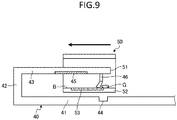
FIG. 9 is a diagram for explaining the operation of the cleaning member according to the second embodiment. -
FIG. 10 is a diagram for explaining the operation of the cleaning member according to the second embodiment. -
FIG. 11 is a diagram showing a modified example of the cleaning member. - To this end, there is provided a receiving / discharging system which includes : a power receiving device, having a power receiving surface and capable of moving in a horizontal direction, and a power supply device having a power supply surface capable of facing the power receiving surface by the horizontal movement of the power receiving device, and supplying power to the power receiving device in a non-contact manner, the power receiving surface and the power supply surface being opposed to each other in the vertical direction. According to the present invention, the receiving / discharging system further comprises a cleaning member provided so as to protrude from an upper surface side between the power receiving surface and the power supply surface to a lower surface side between the power receiving surface and the power supply surface.
- Preferably, a foreign matter housing groove on the power supply device.
- The present invention also relates to a power receiving device according to claim 1 for receiving power from a power supply device in a non-contact manner wherein the power supply device has a power supply surface facing upward, the power receiving device comprising: a movable body movable in a horizontal direction; a power receiving unit provided on the movable body, having a power receiving surface which is formed to face downward and to face the power supply surface of the power supply device by the movement of the movable body in the horizontal direction; and a cleaning member provided to project downward with respect to the receiving surface.
- Preferably, the power receiving unit having a front side and a rear side in a forward-moving direction in which movable body moves to have a power supplying position at which power is supplied in a non-contact manner from the power supply unit via the power supply surface to the power receiving unit and wherein the cleaning member is disposed on the front side of the power receiving unit.
- Preferably, the cleaning member is disposed on each of the front side and the rear side between which the power receiving surface is disposed.
- Preferably, the power receiving device is a shopping cart.
- Preferably, the cleaning member has a width wider than the width of the power receiving surface in a direction perpendicular to the moving-forward direction.
- Preferably, the cleaning member includes a mounting part which is detachably attached to the power receiving unit and a brush (11B) which is provided on the mounting part, the brush having a lower end extending downward from the power receiving surface.
- In this case, the lower end of the clean member is located lower than the power receiving surface in a vertical direction.
- The present invention also relates to a power supply device for supplying power to a power receiving device. The power supply device may comprise a power supply unit having a power supply surface which is formed to face downward and to oppose to a power receiving surface of the power receiving device. The power supply device may further comprise a cleaning member provided so as to protrude downward from the power supply unit.
- Preferably, a groove for accommodating the foreign matter removed by the cleaning member is provided adjacent to the lower surface.
- Hereinafter, as of the first embodiment, a power receiving device, a power supply device, and a power receiving / power supply system including both of the power receiving device and the power supply device will be described with reference to the drawings. In the embodiment, a cart having a scanner is applied as an example of a power receiving device that receives electric power from a power supply device in a non-contact manner. A placement unit of a cart is used as an example of the power supply device. However, the configuration of the power receiving device and the power supply device are arbitrary, and the present invention is not limited thereto.
- First, a
cart 1 which is an example of a power receiving device will be described. Thecart 1 is a handcart used in a store such as a supermarket, and is capable of carrying and transporting goods purchased by a customer. As shown inFIG. 1 , thecart 1 includes amain body 2 composed of a plurality of frames, ahandle portion 3, ahousing part 4 on which a shopping basket or the like is placed, acaster 5, atablet terminal 6, ascanner 7, abattery holder 8, and apower receiving unit 9. Themain body 2 constitutes a movable body and is supported by acaster 5 so as to be movable in the horizontal direction. Thecaster 5 functions as a supporter for supporting themain body 2 so as to be movable in the horizontal direction. - The
handle portion 3 is formed of a portion of the frame of themain body 2 and is provided for the customer to move thecart 1. Thehousing part 4 is formed adjacent to thehandle portion 3, and a basket for storing commodities purchased by the customer is placed thereon. Thecasters 5 are rotatably attached to the four legs of thecart 1. The distance between the pair ofcasters handle portion 3 is wider than the one between the other pair ofcasters casters 5 5 having a narrow distance are provided is defined as a front side, and the side on which the pair ofcasters 5 5 having a wide distance are provided is defined as a rear side. - The
tablet terminal 6 is detachably provided on themain body 2. Thescanner 7 is detachably provided to themain body 2 via a power cord. Thescanner 7 is used by the customer to read information of a bar code attached to a commodity to be purchased by a customer. Thetablet terminal 6 registers commodity information of the commodity to which the barcode is attached, based on the information of the barcode read by thescanner 7. Then, an accounting machine (not shown) performs accounting processing based on the commodity information transmitted from thetablet terminal 6. The accounting processing is defined as a processing for displaying a total amount of money or a tax amount based on the merchandise information, a processing for calculating and displaying a change based on the deposit deposited from the customer, and a process for issuing a receipt on which the commodity information, the settlement information (total amount, deposit amount, change amount, etc.) is printed. Thebattery holder 8 holds a battery for supplying power to thescanner 7. - Next, the power receiving
unit 9 will be described with reference toFIG. 2 - FIG. 4 . Thepower receiving unit 9 is provided on amain body 2 which can be moved in the horizontal direction by acaster 5, and is supplied with electric power from a power supply unit which will be described later. Thepower receiving unit 9 includes a planarpower receiving surface 10 facing downward, acleaning member 11, a power receiving circuit including a power receiving coil (not shown), and a charging circuit. Thepower receiving surface 10 is an electrode surface and is disposed between thecaster 5 on the front side and thecaster 5 on the rear side. The power receiving coil is disposed along thepower receiving surface 10. The power receiving circuit receives electric power from the power supply unit. The charging circuit converts the received power into a DC voltage to charge the battery. - The cleaning
member 11 is provided so as to protrude downward from thepower receiving surface 10. - As shown in
FIGS. 2 and3 , the cleaningmember 11 is disposed on the front side of thepower receiving surface 10, and is provided along the front edge of thepower receiving surface 10. - That is, the cleaning
member 11 is disposed on the front side of thepower receiving surface 10 in a direction (hereinafter referred to as a moving-forward direction) in which thecart 1 is moved when it is accommodated in a placement unit which will be described later. - It is preferable that the width of the cleaning
member 11 in the left-right direction (the direction perpendicular to the moving-forward direction) is wider than the width in the left-right direction of thepower receiving surface 10. - The cleaning
member 11 includes a mountingpart 11A which is detachably attached to a holding portion (not shown) of thepower receiving unit 9, and abrush 11B which is provided on the mountingpart 11A. - The
brush 11B is made of, for example, elastic fibrous bristles, and its lower end projects downward from thepower receiving surface 10. - The cleaning
member 11 may be a thin plate-like rubber blade or the like instead of a bristle shape, and may be bent in the front-rear direction. - The cleaning
member 11 is attachable and detachable to and from thepower receiving unit 9 so as to be replaceable when the function of thebrush 11B is reduced due to deformation of thebrush 11B. - Next, a
placement unit 20 which is a power supply device will be described with reference toFIG. 5 . Theplacement unit 20 is arranged in a cart place in a store of a supermarket and accommodates a plurality of carts which are not used. Theplacement unit 20 includes aguide 21, astopper 22, and a plurality of (four in the embodiment)power supply unit 30. - The
guide 21 guides a pair offront casters 5 of thecart 1, and is provided withguide grooves 25 integrally formed along a longitudinal direction (hereinafter referred to as "front-rear direction") of theplacement unit 20. Theguide groove 25 has awide guide portion 26 in the rear side in the front-rear direction. Theguide groove 25 is provided with apositioning portion 27. Thepositioning part 27 is constituted by a recessed part formed on the bottom surface of theguide groove 25, and when thefront caster 5 of thecart 1 is inserted, thecart 1 is positioned at a position corresponding to the power supply unit. The positioningportion 27 is provided in the same number as thepower supply unit 30 at a predetermined interval in the front-rear direction of theguide groove 25. - The
stopper 22 is positioned at the front end in the front-rear direction of theplacement unit 20 so as to project upward. The width in the left-right direction of thestopper 22 is wider than the width of theguide 21. Thestopper 22 has a function of preventing thecart 1 guided by theguide 21 from jumping forward from theplacement unit 20. - The
power supply unit 30 is positioned between a pair ofguide grooves placement unit 20. Thepower supply unit 30 includes apower supply surface 31 composed of an electrode surface on a plane facing upward, and a power supply circuit provided with a power supply coil (not shown). Thepower supply unit 30 is provided corresponding to thepositioning portion 27. When thecart 1 is positioned at a predetermined position by the positioningportion 27, thepower supply surface 31 is opposed to thepower receiving surface 10 of thecart 1 through a distance of about one centimeter. In this state, electricity is supplied to the power supply coil to generate electromagnetic induction, so that thepower supply unit 30 supplies power to thepower receiving unit 9 in a non-contact manner. As a method of non-contact power supply, various methods such as electromagnetic induction type and magnetic field resonance type are known, but various types of methods can be used. In the present embodiment, the term "non-contact" is used in a state where the power transmission is carried out by wireless. Therefore, even if thepower supply surface 31 and thepower receiving surface 10 are in contact with each other at the time of power supply by some factor, regardless of whether they are intended or not, it is assumed that power is supplied in a non-contact manner if the power transmission is performed by wireless. - The
power supply unit 30 is provided with a foreignmatter housing groove 32 located on the front side of thepower supply surface 31 and abrush housing groove 33 positioned on the front side of the foreignmatter housing groove 32. Each of the foreignmatter housing grooves 32 and thebrush housing grooves 33 has a width in the left-right direction equal to or slightly larger than the width in the left-right direction of thepower supply surface 31. The depth of thebrush housing groove 33 is shallower than the depth of the foreignmatter housing groove 32. -
FIG. 6 shows a state in which fourcarts 1 are placed on aplacement unit 20. As is well known, eachcart 1 which is not used for the customer is arranged such that a portion thereof is overlapped in the front-rear direction. In this state, the power receiving surfaces 10 of thecarts 1 are opposed to each other in the vertical direction on the respective power supply surfaces 31 of theplacement unit 20. In this example, thepower receiving surface 10 is an upper surface, and thepower supply surface 31 is a lower surface. When thecart 1 is not used and is placed on theplacement unit 20, thepower receiving unit 9 charges the battery of thecart 1 with electric power received from thepower supply unit 30. The power receiving / power supply system is constituted by acart 1 as a power receiving device and aplacement unit 20 as a power supply device. - Next, a point in which the
cart 1 is placed on theplacement unit 20 and thepower receiving unit 9 is received from thepower supply unit 30 will be described. When the customer finishes shopping, a customer or a supermarket employee (hereinafter referred to as a customer, etc.) moves thefront caster 5 of thecart 1 into theguide groove 25 through theguide portion 26 of theplacement unit 20. When there are nocarts 1 on theplacement unit 20, thecart 1 is positioned at a position corresponding to the foremost power supply surfaces 31 located on theplacement unit 20. - The customer, etc. pushes the
handle portion 3 of thecart 1 to move thefront caster 5 forward in theguide groove 25. At this time, although thefront caster 5 enters thepositioning portion 27 on theguide portion 26 side once, the customer, etc. can further push thecart 1 forward so as to exceed thepositioning portion 27. Then, after passing through the threepositioning portions 27, thefront caster 5 enters thepositioning portion 27 positioned at the foremost side. Even if the customer, etc. is erroneously pushed forward, thecart 1 is prevented from being moved forward in contact with thestopper 22. As described above, when thecart 1 is positioned at a predetermined position, thepower receiving surface 10 of thepower receiving unit 9 and thepower supply surface 31 of thepower supply unit 30 are opposed to each other in the vertical direction, so that power is supplied to thepower supply unit 27. - The function of the cleaning
member 11 in the process of placing thecart 1 at a predetermined position on theplacement unit 20 will now be described with reference toFIGS. 7 and8 . When a customer, etc. takes thecart 1 into and out of theplacement unit 20, foreign matters such as dust may fall on the supply surface of theplacement unit 20. InFIG. 7 , a foreign matter such as dust is represented by G. - When the
cart 1 is moved along theguide 21 after thefront casters 5 of thecart 1 is positioned in theguide portion 26, the lower end of a cleaningmember 11 provided on the front side of thepower receiving surface 10 in the moving direction is brought into contact with the upper surface A of thepower supply unit 30 and is slightly bent. When a customer, etc. presses thecart 1 from this state, as shown inFIG. 7 , thecart 1 moves, and the cleaningmember 11 moves while abutting against the upper surface A of thepower supply unit 30 and thepower supply surface 31 forming the same surface as the upper surface A. At this time, the cleaningmember 11 cleans the upper surface A and thepower supply surface 31 of thepower supply unit 30 to remove the foreign matters placed thereon. - The cleaning
member 11 sweeps the foreign matter G placed on thepower supply surface 31 located on the foremost side to drop the foreign matter G into the foreignmatter housing groove 32. Thecart 1 is then further moved and positioned in a predetermined place (FIG. 8 ). In this position, thepower receiving surface 10 and thepower supply surface 31 are opposed to each other in the vertical direction. The distal end of the cleaningmember 11 is positioned within thebrush housing groove 33, and the cleaningmember 11 returns from the flexed state to the natural state. - In the embodiment, the
power receiving surface 10 and thepower supply surface 31 are opposed to each other in the vertical direction in a configuration in which the power receiving device is moved in the horizontal direction and the power receiving surface and the power supply surface face are opposed to each other, so that the following advantages are obtained as compared with the case where they are opposed to each other in a horizontal direction. In order to supply power to thepower receiving unit 9 from thepower supply unit 30, it is necessary for thepower receiving surface 10 and thepower supply surface 31 to face each other in an appropriate state. A suitable condition is a predetermined relationship in which both the distance between thepower receiving surface 10 and thepower supply surface 31 in the direction opposite to each other and the position of thepower receiving surface 10 and thepower supply surface 31 in the direction along the surface are made to be able to be supplied with electric power. - In the case where the
caster 5 of thecart 1 is grounded and thecart 1 moves in a state where the distance to the floor surface is constant, the distance between thepower receiving surface 10 and thepower supply surface 31 is kept constant by having the both oppose each other in the vertical direction, in other words, by forming the both along the moving direction. Therefore, there is an advantage that the configuration required when thepower receiving surface 10 and thepower supply surface 31 are opposed to each other in the horizontal direction, that is, the configuration for positioning such that the distance in the direction opposite to each other is constant, becomes unnecessary. In the embodiment, the following effects can be obtained on the assumption that this configuration is provided. - According to the embodiment, as described above, when the
cart 1 is moved so that thepower receiving surface 10 and thepower supply surface 31 are opposed to each other, the cleaningmember 11 provided on the front side (front side in the moving direction of the cart 1) of thepower receiving surface 10 and projecting downward sweeps the upper surface of thepower supply surface 31 while abutting on thepower supply surface 31. - Thus, the foreign matter placed on the upper surface of the
power supply surface 31 can be removed, so that a decrease in power supply efficiency from thepower supply unit 30 to thepower receiving unit 9 can be reduced. - More specifically, in the case where the power supply is performed in a state where foreign matter such as metal is placed on the
power supply surface 31 and is positioned between thepower receiving surface 10 and thepower supply surface 31, the metal is subjected to the magnetic flux energy from thepower supply unit 30 to generate heat, which causes loss, but in accordance with the embodiment, the decrease of power supply efficiency can be reduced. - Moreover, since the foreign matters on the
power supply surface 31 are removed accompanying the operation of housing thecart 1 at a predetermined position, it is not necessary to perform any special operation for removing the foreign matter, so that it is possible to easily suppress the deterioration of the power supply efficiency. - Further, according to the embodiment, since the foreign
matter housing groove 32 for housing the foreign matter removed accompanying the operation of housing thecart 1 at a predetermined position is provided, the removed foreign matter is not scattered. Therefore, it is only necessary to clean the foreignmatter housing groove 32, and it is not necessary to carry out troublesome cleaning. Further, when a cartridge attachable to and detachable from the foreignmatter housing groove 32 is provided, disposal of foreign matters can be made easier. - In addition, according to the embodiment, since the
brush housing groove 33 for receiving the tip of thebrush 11B is provided in a state where thecart 1 is positioned at a predetermined position where thepower receiving surface 10 and thepower supply surface 31 are opposed to each other, it is possible to suppress deterioration in durability of the cleaningmember 11. That is, since thebrush 11B has a function of removing foreign matters by sweeping on thepower supply surface 31, when it is on thepower supply unit 30, it is in a bent state, but when thecart 1 is housed in a predetermined position for a long time, it becomes natural. Accordingly, deformation of thebrush 11B can be suppressed, and as a result, deterioration in durability of the cleaningmember 11 can be suppressed. - Next, a second embodiment will be described with reference to
FIG. 9 andFIG. 10 .FIGS. 9 and10 show acart 1 and a part of aplacement unit 20. This embodiment differs from the above-described embodiment in the four followings. The number of power supply device unit provided on the placement unit is one. The power supply surface constitutes an upper surface and is formed downward. The power receiving surface constitutes a lower surface and is formed upward. The cleaning member is provided on the placement unit side to sweep the power receiving surface. - The
placement unit 40 constitutes a power supply device for supplying power to a power receiving device which can move in the horizontal direction in a non-contact manner, and includes abottom surface part 41, asupport arm part 42 and apower supply unit 43. Thebottom surface part 41 is provided with a foreignmatter housing groove 44. Thesupport arm part 42 is formed to extend upward from thebottom surface part 41 and supports thepower supply unit 43 in a state spaced upward from thebottom surface part 41. Thepower supply unit 43 includes apower supply surface 45 to be formed downward, and a cleaningmember 46 disposed behind thepower supply surface 45. Here, the side receiving the cart 50 (the right side inFIG. 9 ) is defined to as the rear side. - On the other hand, the
cart 50 has asupport part 51 at a front end portion thereof. - The
support part 51 is provided with apower receiving unit 52 which is parallel to thepower supply unit 43. - The
power receiving surface 53 formed in thepower receiving unit 52 is formed upward so as to be able to face thepower supply surface 45 in the vertical direction. - With reference to
FIGS. 9 and10 , the function of cleaningmember 46 in the course of thecart 50 being placed in a predetermined position inplacement unit 40 will now be described. When there are many customers, a foreign matter G such as dust may be placed on apower receiving surface 53 provided on thecart 1 during shopping. The cleaningmember 46 removes the foreign matter G on thepower receiving surface 53 in conjunction with the operation of housing thecart 50 in theplacement unit 40. - As in the description of
FIGS. 7 and8 , when thecart 50 is moved in the direction of the arrow, the lower end of a cleaningmember 46 provided in thepower supply unit 43 in the is brought into contact with the upper surface B of thepower receiving unit 52 and is slightly bent. When thecart 50 further moves from this state, the cleaningmember 46 comes into contact with the upper surface B of thepower receiving unit 52 and the receivingsurface 53 which forms the same surface as thepower receiving unit 52. At this time, the cleaningmember 46 cleans the upper surface B and thepower receiving surface 53 of thepower receiving unit 52 to remove foreign matters placed thereon. - Thereafter, the
cart 50 is further moved, and when thepower receiving surface 53 and thepower supply surface 45 are in a predetermined position opposed to each other in the vertical direction, thecart 50 is positioned on theplacement unit 40. In this state, as shown inFIG. 10 , the cleaningmember 46 is separated from the upper surface B of thepower receiving unit 52 and returns to its natural state. At this time, the foreign matter G removed by the cleaningmember 46 is housed in the foreignmatter housing groove 44. - According to the second embodiment, as described above, the
cart 50 moves and the cleaningmember 46 sweeps thepower receiving surface 53 to remove the foreign matter placed thereon. Therefore, the foreign matters on thepower receiving surface 53 formed upward can be removed before the power supply from thepower supply unit 43 to thepower receiving unit 52. Therefore, as in the embodiment described above, it is possible to prevent the power supply from being performed in a state where the foreign matter is positioned between thepower receiving surface 53 and thepower supply surface 45, so that it is possible to suppress the reduction in the power supply efficiency. - Next, a modified example relating to the cleaning
member 11 will be described with reference toFIG. 11. FIG. 11 shows a modified example of thepower receiving unit 9 according to the first embodiment or thepower supply unit 43 according to the second embodiment. Here, thepower receiving unit 9 according to the first embodiment will be described. In addition, thepower supply unit 43 will be described with reference to the corresponding configuration numbers. - The difference from the first embodiment is that the cleaning
member 11 is disposed on the front side and the rear side in the
moving direction of thecart 1 with a power receiving surfaces 10 interposed therebetween. The movement direction of thecart 1 is the direction in which thecart 1 moves along theguide 21. - According to the above structure, when the
cart 1 is moved to a predetermined position where thepower receiving surface 10 and thepower supply surface 31 face each other, even if thecart 1 is erroneously moved to a position beyond a predetermined position, and it is left in this state for a fixed time, the foreign matter on thepower supply surface 31 can be removed before supplied with electric power. This is because when thecart 1 is returned from a position beyond a predetermined position to a predetermined position, the cleaningmember 11 disposed on the rear side of thepower receiving surface 10 can sweep thepower supply surface 31. When the cleaningmember 46 in the second embodiment is disposed on the front side and the rear side in the moving direction of thecart 1 with thepower supply surface 45 interposed therebetween, the same effect can be obtained that foreign matters on thepower receiving surface 53 can be removed before supplied with electric power. - While certain embodiments have been described, these embodiments have been presented by way of example only, and are not intended to limit the scope of the inventions. Indeed, the novel embodiments described herein may be embodied in a variety of other forms; furthermore, various omissions, substitutions and changes in the form of the embodiments described herein may be made without departing from the scope of the inventions. The accompanying claims and their equivalents are intended to cover such forms or modifications as would fall within the scope of the inventions.
- For example, in the embodiment, the power receiving device is applied to a cart of a POS system using a cart, but may be applied to a self-propelled robot equipped with a battery, for example. In addition, in the embodiment, the power supply device is applied to a placement unit including a plurality of power supply units, but it may also be applied to a case where only one power supply units are provided.
- In the embodiment, the caster is used as the structure for movably supporting the power receiving device on the surface to be mounted such as a floor, but the caster is not limited to the caster as long as it is supported so as to be movable in the horizontal direction.
- In addition, although a brush having a length which is in contact with the power receiving surface and the power receiving surface opposite to each other is adopted as a cleaning member, it does not necessarily have to come into contact with the power supply surface or the power receiving surface, but is not required to be contactable and flexible, as long as it can remove foreign matters on the surface.
Claims (11)
- A receiving / discharging system including : a power receiving device (1), having a power receiving surface (10) and capable of moving in a horizontal direction, and a power supply device (20) having a power supply surface (31) capable of facing the power receiving surface by the horizontal movement of the power receiving device, and supplying power to the power receiving device in a non-contact manner, the power receiving surface and the power supply surface being opposed to each other in the vertical direction;
characterized in that the receiving / discharging system further comprises a cleaning member provided so as to protrude from an upper surface side between the power receiving surface and the power supply surface to a lower surface side between the power receiving surface and the power supply surface. - The receiving / discharging system according to claim 1, wherein a groove for accommodating the foreign matter removed by the cleaning member is provided on to the lower surface.
- A power receiving device (1) according to claim 1 or 2 for receiving power from a power supply device in a non-contact manner wherein the power supply device (20) has a power supply surface (31) facing upward, the power receiving device (1) comprising:- a movable body (2) movable in a horizontal direction;- a power receiving unit (9) provided on the movable body (2), having a power receiving surface (10) which is formed to face downward and to face the power supply surface (31) of the power supply device (30) by the movement of the movable body in the horizontal direction; and- a cleaning member (11) provided to project downward with respect to the receiving surface (10).
- The power receiving device according to claim 3, wherein the power receiving unit (9) having a front side and a rear side in a forward-moving direction in which movable body (2) moves to have a power supplying position at which power is supplied in a non-contact manner from the power supply unit via the power supply surface (31) to the power receiving unit (9) and wherein the cleaning member (11) is disposed on the front side of the power receiving unit (9).
- The power receiving device according to claim 4, wherein the cleaning member (11) is disposed on each of the front side and the rear side between which the power receiving surface (10) is disposed.
- The power receiving device according to any one of claims 1 to 5, wherein the power receiving device is a cart (1).
- The power receiving device according to any one of claims 1 to 6, wherein the cleaning member (11) has a width wider than the width of the power receiving surface (10) in a direction perpendicular to the moving-forward direction.
- The power receiving device according to any one of claims 1 to 7, wherein the cleaning member (11) includes a mounting part (11A) which is detachably attached to the power receiving unit (9) and a brush (11B) which is provided on the mounting part (11A), the brush (11B) having a lower end extending downward from the power receiving surface (10).
- A power supply device (40) for supplying power to a power receiving device (1) according to claim 1 comprising a power supply unit (43) having a power supply surface (45) which is formed to face downward and to oppose to a power receiving surface (53) of the power receiving device (50), characterized by further comprising a cleaning member provided so as to protrude downward from the power supply unit (43) .
- The power supply device (40) according to claim 9, comprising a bottom surface part (41) formed to oppose the power supply unit (43) and a support arm part (42) connecting the bottom surface part (41) and the power supply unit (43).
- The power supply device (40) according to claim 10, wherein a groove (44) for accommodating the foreign matter removed by the cleaning member is provided on the bottom surface part (41).
Applications Claiming Priority (1)
| Application Number | Priority Date | Filing Date | Title |
|---|---|---|---|
| JP2019124054A JP7424765B2 (en) | 2019-07-02 | 2019-07-02 | Power receiving system |
Publications (1)
| Publication Number | Publication Date |
|---|---|
| EP3761479A1 true EP3761479A1 (en) | 2021-01-06 |
Family
ID=71514923
Family Applications (1)
| Application Number | Title | Priority Date | Filing Date |
|---|---|---|---|
| EP20182387.9A Pending EP3761479A1 (en) | 2019-07-02 | 2020-06-25 | Power receiving device, power supply device, and power receiving power supply system |
Country Status (4)
| Country | Link |
|---|---|
| US (1) | US20210001911A1 (en) |
| EP (1) | EP3761479A1 (en) |
| JP (1) | JP7424765B2 (en) |
| CN (1) | CN112186824B (en) |
Cited By (1)
| Publication number | Priority date | Publication date | Assignee | Title |
|---|---|---|---|---|
| EP3793060B1 (en) * | 2019-09-10 | 2025-06-18 | Toshiba Tec Kabushiki Kaisha | Wireless power supply system and wireless power transmission device |
Families Citing this family (6)
| Publication number | Priority date | Publication date | Assignee | Title |
|---|---|---|---|---|
| JP6942659B2 (en) * | 2018-03-02 | 2021-09-29 | 東芝テック株式会社 | cart |
| JP7514683B2 (en) * | 2020-07-28 | 2024-07-11 | 東芝テック株式会社 | Non-contact power supply device |
| CN113335089A (en) * | 2021-06-26 | 2021-09-03 | 深圳欣锐科技股份有限公司 | Electric energy receiving platform, charging system and vehicle |
| JP7662453B2 (en) * | 2021-08-23 | 2025-04-15 | 東芝テック株式会社 | Non-contact power supply device |
| JP7664797B2 (en) * | 2021-09-03 | 2025-04-18 | 東芝テック株式会社 | Carts and Spacers |
| WO2024021047A1 (en) * | 2022-07-29 | 2024-02-01 | Maplebear Inc. | Stackable charging device for shopping carts with onboard computing systems |
Citations (6)
| Publication number | Priority date | Publication date | Assignee | Title |
|---|---|---|---|---|
| JP2006101577A (en) * | 2004-09-28 | 2006-04-13 | Dainippon Printing Co Ltd | Non-contact power feeding method and apparatus for vehicle |
| JP2012019907A (en) * | 2010-07-13 | 2012-02-02 | Okamura Corp | Furniture system |
| JP2017131008A (en) * | 2016-01-19 | 2017-07-27 | 富士通株式会社 | Power transmitter, power receiver and wireless power transmission system |
| KR20180029795A (en) * | 2016-09-13 | 2018-03-21 | 엘지이노텍 주식회사 | Cart including a wireless power tranceiver and wireless power transmitter |
| JP2018130008A (en) * | 2017-02-09 | 2018-08-16 | パナソニックIpマネジメント株式会社 | Method for controlling power transmission device in wireless power transmission system, and power transmission device |
| CN208890487U (en) * | 2018-11-08 | 2019-05-21 | 江苏木盟智能科技有限公司 | A kind of wireless charging foreign matter detection mechanism |
Family Cites Families (16)
| Publication number | Priority date | Publication date | Assignee | Title |
|---|---|---|---|---|
| JP4498096B2 (en) * | 2004-10-28 | 2010-07-07 | 大日本印刷株式会社 | Manufacturing method of non-contact power feeding device |
| JP4608282B2 (en) * | 2004-10-28 | 2011-01-12 | 大日本印刷株式会社 | Non-contact power feeding method and apparatus |
| JP4469290B2 (en) | 2005-02-01 | 2010-05-26 | 大日本印刷株式会社 | Power supply apparatus and power supply method |
| DE102009049432B4 (en) * | 2009-10-14 | 2024-11-28 | Sew-Eurodrive Gmbh & Co Kg | charging station |
| JP2013048511A (en) | 2011-08-29 | 2013-03-07 | Panasonic Corp | Electric vehicle |
| JP5974710B2 (en) | 2012-07-27 | 2016-08-23 | 株式会社Ihi | Foreign matter removal mechanism |
| JP5998737B2 (en) * | 2012-08-16 | 2016-09-28 | 株式会社Ihi | Mobile parking facilities |
| JP6145318B2 (en) * | 2013-05-31 | 2017-06-07 | 小島プレス工業株式会社 | Contactless power transmission equipment |
| JP2015015818A (en) * | 2013-07-04 | 2015-01-22 | アルパイン株式会社 | Non-contact type power transmission system and mobile body |
| EP3457524B1 (en) * | 2014-06-06 | 2020-03-25 | IHI Corporation | Power-transmitting device, power-receiving device, and wireless power supply system |
| CN205513503U (en) * | 2016-03-28 | 2016-08-31 | 邵阳学院 | Multi -functional seat of waiting |
| US10575696B2 (en) * | 2016-07-13 | 2020-03-03 | Irobot Corporation | Autonomous robot auto-docking and energy management systems and methods |
| US10910888B2 (en) * | 2017-10-24 | 2021-02-02 | Stryker Corporation | Power transfer system with patient transport apparatus and power transfer device to transfer power to the patient transport apparatus |
| US20190207427A1 (en) * | 2017-12-31 | 2019-07-04 | Blynk Technology | Methods and apparatuses for powering electrical systems onboard carts |
| KR102559985B1 (en) * | 2018-08-23 | 2023-07-26 | 삼성전자주식회사 | Autonomous moving device and docking station thereof |
| CN208653611U (en) * | 2018-08-27 | 2019-03-26 | 徐天宏 | A kind of trolley weighing positioning device |
-
2019
- 2019-07-02 JP JP2019124054A patent/JP7424765B2/en active Active
-
2020
- 2020-05-18 US US16/876,355 patent/US20210001911A1/en not_active Abandoned
- 2020-06-10 CN CN202010523510.2A patent/CN112186824B/en active Active
- 2020-06-25 EP EP20182387.9A patent/EP3761479A1/en active Pending
Patent Citations (6)
| Publication number | Priority date | Publication date | Assignee | Title |
|---|---|---|---|---|
| JP2006101577A (en) * | 2004-09-28 | 2006-04-13 | Dainippon Printing Co Ltd | Non-contact power feeding method and apparatus for vehicle |
| JP2012019907A (en) * | 2010-07-13 | 2012-02-02 | Okamura Corp | Furniture system |
| JP2017131008A (en) * | 2016-01-19 | 2017-07-27 | 富士通株式会社 | Power transmitter, power receiver and wireless power transmission system |
| KR20180029795A (en) * | 2016-09-13 | 2018-03-21 | 엘지이노텍 주식회사 | Cart including a wireless power tranceiver and wireless power transmitter |
| JP2018130008A (en) * | 2017-02-09 | 2018-08-16 | パナソニックIpマネジメント株式会社 | Method for controlling power transmission device in wireless power transmission system, and power transmission device |
| CN208890487U (en) * | 2018-11-08 | 2019-05-21 | 江苏木盟智能科技有限公司 | A kind of wireless charging foreign matter detection mechanism |
Cited By (1)
| Publication number | Priority date | Publication date | Assignee | Title |
|---|---|---|---|---|
| EP3793060B1 (en) * | 2019-09-10 | 2025-06-18 | Toshiba Tec Kabushiki Kaisha | Wireless power supply system and wireless power transmission device |
Also Published As
| Publication number | Publication date |
|---|---|
| JP7424765B2 (en) | 2024-01-30 |
| CN112186824B (en) | 2024-10-29 |
| US20210001911A1 (en) | 2021-01-07 |
| CN112186824A (en) | 2021-01-05 |
| JP2021010273A (en) | 2021-01-28 |
Similar Documents
| Publication | Publication Date | Title |
|---|---|---|
| US20210001911A1 (en) | Power receiving device, power supply device, and power supply system | |
| JP7443035B2 (en) | mobile object | |
| JP6942659B2 (en) | cart | |
| US8985444B2 (en) | Checkout stand with a barcode reader on a bagging end | |
| EP3761481B1 (en) | Non-contact power supply unit | |
| US20220185134A1 (en) | Non-contact power supply device | |
| CN102945357B (en) | Light code scanner and in light code scanner the method for bar code reading | |
| CN112491152B (en) | Non-contact power supply system and power transmission device | |
| US11866083B2 (en) | Mobile body and terminal case to be attached to the same | |
| CN112787420A (en) | Power transmission device and power transmission and reception system | |
| US20230070487A1 (en) | Stackable carts with electronic apparatus and spacer for stackable carts | |
| JP2023030273A (en) | Non-contact power feeding device | |
| CN114537498B (en) | Power supply device | |
| US4330048A (en) | Cooperative bagging check-out counter | |
| US12199459B2 (en) | Moving device power feeding device | |
| JP2024040633A (en) | shopping cart | |
| CN110503787B (en) | Cashier system convenient for checkout and vending shop | |
| JP2004130952A (en) | Cart | |
| CN214796050U (en) | Sharing is charged treasured and machine integral type wisdom machine is selld to goods | |
| CN213303190U (en) | Sweep a yard payment terminal equipment | |
| JP2017021639A (en) | Cash register settlement system and cash register settlement method | |
| CN215622200U (en) | Multifunctional shopping cart | |
| CN221899606U (en) | Vertical damage-proof large-screen self-service machine | |
| CN211375723U (en) | Supermarket automatic cash register supporting WeChat payment | |
| CN212878694U (en) | Intelligent cash register |
Legal Events
| Date | Code | Title | Description |
|---|---|---|---|
| PUAI | Public reference made under article 153(3) epc to a published international application that has entered the european phase |
Free format text: ORIGINAL CODE: 0009012 |
|
| STAA | Information on the status of an ep patent application or granted ep patent |
Free format text: STATUS: THE APPLICATION HAS BEEN PUBLISHED |
|
| AK | Designated contracting states |
Kind code of ref document: A1 Designated state(s): AL AT BE BG CH CY CZ DE DK EE ES FI FR GB GR HR HU IE IS IT LI LT LU LV MC MK MT NL NO PL PT RO RS SE SI SK SM TR |
|
| AX | Request for extension of the european patent |
Extension state: BA ME |
|
| STAA | Information on the status of an ep patent application or granted ep patent |
Free format text: STATUS: REQUEST FOR EXAMINATION WAS MADE |
|
| 17P | Request for examination filed |
Effective date: 20210706 |
|
| RBV | Designated contracting states (corrected) |
Designated state(s): AL AT BE BG CH CY CZ DE DK EE ES FI FR GB GR HR HU IE IS IT LI LT LU LV MC MK MT NL NO PL PT RO RS SE SI SK SM TR |
|
| STAA | Information on the status of an ep patent application or granted ep patent |
Free format text: STATUS: EXAMINATION IS IN PROGRESS |
|
| 17Q | First examination report despatched |
Effective date: 20220607 |