EP3761419B1 - Electrode and electrode assembly - Google Patents
Electrode and electrode assembly Download PDFInfo
- Publication number
- EP3761419B1 EP3761419B1 EP19911595.7A EP19911595A EP3761419B1 EP 3761419 B1 EP3761419 B1 EP 3761419B1 EP 19911595 A EP19911595 A EP 19911595A EP 3761419 B1 EP3761419 B1 EP 3761419B1
- Authority
- EP
- European Patent Office
- Prior art keywords
- active material
- coating portion
- cathode
- anode
- electrode
- Prior art date
- Legal status (The legal status is an assumption and is not a legal conclusion. Google has not performed a legal analysis and makes no representation as to the accuracy of the status listed.)
- Active
Links
Images



Classifications
-
- H—ELECTRICITY
- H01—ELECTRIC ELEMENTS
- H01M—PROCESSES OR MEANS, e.g. BATTERIES, FOR THE DIRECT CONVERSION OF CHEMICAL ENERGY INTO ELECTRICAL ENERGY
- H01M4/00—Electrodes
- H01M4/02—Electrodes composed of, or comprising, active material
- H01M4/62—Selection of inactive substances as ingredients for active masses, e.g. binders, fillers
-
- H—ELECTRICITY
- H01—ELECTRIC ELEMENTS
- H01M—PROCESSES OR MEANS, e.g. BATTERIES, FOR THE DIRECT CONVERSION OF CHEMICAL ENERGY INTO ELECTRICAL ENERGY
- H01M10/00—Secondary cells; Manufacture thereof
- H01M10/05—Accumulators with non-aqueous electrolyte
- H01M10/052—Li-accumulators
-
- H—ELECTRICITY
- H01—ELECTRIC ELEMENTS
- H01M—PROCESSES OR MEANS, e.g. BATTERIES, FOR THE DIRECT CONVERSION OF CHEMICAL ENERGY INTO ELECTRICAL ENERGY
- H01M10/00—Secondary cells; Manufacture thereof
- H01M10/05—Accumulators with non-aqueous electrolyte
- H01M10/058—Construction or manufacture
-
- H—ELECTRICITY
- H01—ELECTRIC ELEMENTS
- H01M—PROCESSES OR MEANS, e.g. BATTERIES, FOR THE DIRECT CONVERSION OF CHEMICAL ENERGY INTO ELECTRICAL ENERGY
- H01M10/00—Secondary cells; Manufacture thereof
- H01M10/42—Methods or arrangements for servicing or maintenance of secondary cells or secondary half-cells
- H01M10/4235—Safety or regulating additives or arrangements in electrodes, separators or electrolyte
-
- H—ELECTRICITY
- H01—ELECTRIC ELEMENTS
- H01M—PROCESSES OR MEANS, e.g. BATTERIES, FOR THE DIRECT CONVERSION OF CHEMICAL ENERGY INTO ELECTRICAL ENERGY
- H01M4/00—Electrodes
- H01M4/02—Electrodes composed of, or comprising, active material
- H01M4/13—Electrodes for accumulators with non-aqueous electrolyte, e.g. for lithium-accumulators; Processes of manufacture thereof
-
- H—ELECTRICITY
- H01—ELECTRIC ELEMENTS
- H01M—PROCESSES OR MEANS, e.g. BATTERIES, FOR THE DIRECT CONVERSION OF CHEMICAL ENERGY INTO ELECTRICAL ENERGY
- H01M50/00—Constructional details or processes of manufacture of the non-active parts of electrochemical cells other than fuel cells, e.g. hybrid cells
- H01M50/10—Primary casings; Jackets or wrappings
- H01M50/102—Primary casings; Jackets or wrappings characterised by their shape or physical structure
- H01M50/105—Pouches or flexible bags
-
- H—ELECTRICITY
- H01—ELECTRIC ELEMENTS
- H01M—PROCESSES OR MEANS, e.g. BATTERIES, FOR THE DIRECT CONVERSION OF CHEMICAL ENERGY INTO ELECTRICAL ENERGY
- H01M50/00—Constructional details or processes of manufacture of the non-active parts of electrochemical cells other than fuel cells, e.g. hybrid cells
- H01M50/10—Primary casings; Jackets or wrappings
- H01M50/172—Arrangements of electric connectors penetrating the casing
- H01M50/174—Arrangements of electric connectors penetrating the casing adapted for the shape of the cells
- H01M50/178—Arrangements of electric connectors penetrating the casing adapted for the shape of the cells for pouch or flexible bag cells
-
- H—ELECTRICITY
- H01—ELECTRIC ELEMENTS
- H01M—PROCESSES OR MEANS, e.g. BATTERIES, FOR THE DIRECT CONVERSION OF CHEMICAL ENERGY INTO ELECTRICAL ENERGY
- H01M50/00—Constructional details or processes of manufacture of the non-active parts of electrochemical cells other than fuel cells, e.g. hybrid cells
- H01M50/50—Current conducting connections for cells or batteries
- H01M50/543—Terminals
-
- H—ELECTRICITY
- H01—ELECTRIC ELEMENTS
- H01M—PROCESSES OR MEANS, e.g. BATTERIES, FOR THE DIRECT CONVERSION OF CHEMICAL ENERGY INTO ELECTRICAL ENERGY
- H01M4/00—Electrodes
- H01M4/02—Electrodes composed of, or comprising, active material
- H01M2004/026—Electrodes composed of, or comprising, active material characterised by the polarity
- H01M2004/028—Positive electrodes
-
- H—ELECTRICITY
- H01—ELECTRIC ELEMENTS
- H01M—PROCESSES OR MEANS, e.g. BATTERIES, FOR THE DIRECT CONVERSION OF CHEMICAL ENERGY INTO ELECTRICAL ENERGY
- H01M50/00—Constructional details or processes of manufacture of the non-active parts of electrochemical cells other than fuel cells, e.g. hybrid cells
- H01M50/50—Current conducting connections for cells or batteries
- H01M50/531—Electrode connections inside a battery casing
- H01M50/534—Electrode connections inside a battery casing characterised by the material of the leads or tabs
-
- Y—GENERAL TAGGING OF NEW TECHNOLOGICAL DEVELOPMENTS; GENERAL TAGGING OF CROSS-SECTIONAL TECHNOLOGIES SPANNING OVER SEVERAL SECTIONS OF THE IPC; TECHNICAL SUBJECTS COVERED BY FORMER USPC CROSS-REFERENCE ART COLLECTIONS [XRACs] AND DIGESTS
- Y02—TECHNOLOGIES OR APPLICATIONS FOR MITIGATION OR ADAPTATION AGAINST CLIMATE CHANGE
- Y02E—REDUCTION OF GREENHOUSE GAS [GHG] EMISSIONS, RELATED TO ENERGY GENERATION, TRANSMISSION OR DISTRIBUTION
- Y02E60/00—Enabling technologies; Technologies with a potential or indirect contribution to GHG emissions mitigation
- Y02E60/10—Energy storage using batteries
-
- Y—GENERAL TAGGING OF NEW TECHNOLOGICAL DEVELOPMENTS; GENERAL TAGGING OF CROSS-SECTIONAL TECHNOLOGIES SPANNING OVER SEVERAL SECTIONS OF THE IPC; TECHNICAL SUBJECTS COVERED BY FORMER USPC CROSS-REFERENCE ART COLLECTIONS [XRACs] AND DIGESTS
- Y02—TECHNOLOGIES OR APPLICATIONS FOR MITIGATION OR ADAPTATION AGAINST CLIMATE CHANGE
- Y02P—CLIMATE CHANGE MITIGATION TECHNOLOGIES IN THE PRODUCTION OR PROCESSING OF GOODS
- Y02P70/00—Climate change mitigation technologies in the production process for final industrial or consumer products
- Y02P70/50—Manufacturing or production processes characterised by the final manufactured product
Definitions
- the present invention relates to an electrode and an electrode assembly, and more particularly, to an electrode in which initial heat generation is suppressed through heat absorption reaction of a flame retardant when an abnormal operation such as internal short circuit, external short circuit, overcharge, overdischarge, and the like occurs, thereby securing safety, and an electrode assembly.
- secondary batteries include nickelcadmium batteries, nickel-hydrogen batteries, lithium ion batteries, and lithium ion polymer batteries.
- Such a secondary battery is being applied to and used in small-sized products such as digital cameras, P-DVDs, MP3Ps, mobile phones, PDAs, portable game devices, power tools, E-bikes, and the like as well as large-sized products requiring high power such as electric vehicles and hybrid vehicles, power storage devices for storing surplus power or renewable energy, and backup power storage devices.
- a cathode, a separator, and an anode are manufactured and stacked. Specifically, cathode active material slurry is applied to a cathode collector, and anode active material slurry is applied to an anode collector to manufacture a cathode and an anode. Also, when the separator is interposed and stacked between the manufactured cathode and anode, unit cells are formed. The unit cells are stacked on each other to form an electrode assembly. Also, when the electrode assembly is accommodated in a specific case, and an electrolyte is injected, the secondary battery is manufactured.
- KR20030042578A relates to a secondary battery having a short circuit prevention means.
- KR101595607B1 relates to a secondary battery with improved safety.
- KR100956397B1 discloses a pack for a battery pack comprising a flame-retardant and heat-resistant resin composition.
- KR20130064031A discloses a battery pack wherein a flame retardant is covering a part of the battery case.
- KR20180043232A relates to a secondary battery wherein a flame retardant film includes a flame retardant polymer.
- the separator when an abnormal operation such as exposure of the secondary battery at a high temperature, internal/external short circuit, overcharging, or overdischarging occurs, the separator is contracted due to generated heat, and thus, the cathode and the anode directly contact each other to increase in possibility of occurrence of the short circuit.
- the short circuit may occur due to the contact between the cathode and the anode due to poor battery production. Due to the short circuit, rapid electron transfer may occur inside the battery, and thus, when the heat generation and side reactions occur, the secondary battery may be exploded to cause a safety problem.
- the temperature of the collector is higher than that of the active material layer. Thereafter, the heat may be diffused, and thus, thermal, chemical, and electrochemical reactions of components such as the active materials and the electrolytes may be added to lead to thermal runaway.
- An object of the prevent invention is to provide an electrode in which short circuit due to contact between a cathode and an anode, which may occur when a battery is manufactured, is prevented when an abnormal operation such as internal short circuit, external short circuit, overcharge, overdischarge, and the like occurs, and simultaneously, initial heat generation is suppressed through heat absorption reaction of a flame retardant to secure safety, and an electrode assembly.
- An electrode according to an embodiment of the present invention for solving the above problem includes: an active material coating portion coated with an electrode active material on at least one surface of an electrode collector; an active material non-coating portion which is formed on one side of the active material coating portion and is not coated with the electrode active material; and an electrode coating portion which is coated between the active material coating portion and the active material non-coating portion and contains a flame retardant.
- the electrode collector may be a cathode collector
- the electrode active material may be a cathode active material
- the flame retardant may include halogen-based flame retardants, phosphorus-based flame retardants, or inorganic compound flame retardants.
- the flame retardant may include aluminum hydroxide (Al(OH) 3 ), magnesium hydroxide (Mg(OH) 2 ), or boric acid (BH 3 O 3 ) .
- the electrode coating portion includes an interface between the active material coating portion and the active material non-coating portion.
- the active material coating portion and the active material non-coating portion may be formed on a same surface of the electrode collector.
- An electrode assembly for solving the above problem includes: a cathode including a cathode active material coating portion coated with a cathode active material on at least one surface of a cathode collector, a cathode active material non-coating portion which is formed on one side of the cathode active material coating portion and is not coated with the cathode active material, and a cathode coating portion which is coated between the cathode active material coating portion and the cathode active material non-coating portion and contains a flame retardant; an anode including an anode active material coating portion coated with an anode active material on at least one surface of an anode collector, an anode active material non-coating portion which is formed on one side of the anode active material coating portion and is not coated with the anode active material; and a separator disposed between the cathode and the anode.
- the anode may further include an anode coating portion which is coated between the anode active material coating portion and the anode active material non-coating portion and contains a flame retardant.
- the present invention also provide a secondary battery including the electrode assembly.
- the secondary battery may further include: a plurality of electrode tabs respectively protruding to sides from the cathode and the anode; a plurality of electrode leads respectively connected to the electrode tabs to transfer electricity generated in the electrode assembly to the outside; a battery case configured to accommodate the electrode assembly therein; and an insulation part configured to surround the electrode leads, sealed with the battery case, and containing a flame retardant.
- the embodiments of the present invention may have at least the following effects.
- the non-conductive coating portion containing the flame retardant is coated between the active material coating portion and the active material non-coating portion, the short circuit between the cathode and the anode by the damage, the folding, and the like of the separator due to the defects and the abnormal operation of the battery when the battery is produced may be prevented.
- the flame retardant may suppress the initial heat generation to secure the safety.
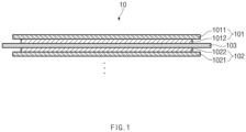
- FIG. 1 is a schematic view of an electrode assembly 10 according to an embodiment of the present invention.
- a process of manufacturing the electrode assembly 10 in a process of manufacturing the electrode assembly 10 according to an embodiment of the present invention, as described above, first, slurry in which a cathode active material 1012, a binder, and a plasticizer are mixed is applied to a cathode collector 1011, and slurry in which an anode active material 1022, the binder, and the plasticizer are mixed is applied to an anode collector 1021 to manufacture a cathode 101 and an anode 102. Also, when a separator 103 is disposed between the manufactured cathode 101 and the manufactured anode 102 so as to be stacked, unit cells are formed. Then, the unit cells are stacked on each other to form the electrode assembly 10 having a predetermined shape as illustrated in FIG. 1 .
- the cathode 101 and the anode 102 which are used in the present invention, are not particularly limited to both electrodes 101 and 102 and thus may be manufactured in a shape in which the electrode active materials 1012 and 1022 are bonded to the electrode collectors 1011 and 1021 according to the conventional method known in the art.
- the cathode 101 may be manufactured by, for example, applying the slurry, in which the cathode active material 1012, the conductive agent, and the binder are mixed, onto a cathode collector 1011, and then drying and pressing the slurry. At this time, if necessary, the slurry may further include a filler.
- the cathode 101 may be manufactured in a sheet shape and mounted on a roll.
- the cathode collector 1011 generally has a thickness of 3 um to 500 um.
- the cathode collector 1011 is usually made of a material having high conductivity without causing a chemical change. Such a material may be surface-treated with, for example, stainless steel, aluminum, nickel, titanium, calcined carbon, or aluminum or stainless steel on which carbon, nickel, titanium, silver, or the like is surface-treated on a surface thereof, but is not limited thereto.
- the cathode collector 1011 may form a fine unevenness on a surface of the cathode collector 1012 to increase in adhesion of the cathode active material 1012.
- the cathode collector 1011 may have various shapes such as a film, a sheet, a foil, a net, a porous body, a foam, or a non-woven fabric.
- the conductive agent is generally added at 1% to about 50% by weight based on the total weight of the mixture including the cathode active material 1012.
- the conductive agent is usually made of a material having conductivity without causing a chemical change.
- the conductive agent may include, for example, conductive materials such as: graphite such as natural graphite and artificial graphite; carbon black such as acetylene black, Ketjen black, channel black, furnace black, lamp black, and thermal black; conductive fiber such as carbon fiber and metal fiber; metal powder such as carbon fluorine, aluminum, and nickel powder; conductive whisker such as zinc oxide and potassium titanate; conductive oxide such as titanium oxide; or polyphenylene derivatives.
- the binder is a component assisting the bonding of the active material to the conductive material and the bonding to the collector and is commonly added at 1 wt% to 50 wt% based on the total weight of the mixture including the cathode active material 1012.
- the binder may include polyfluoro vinylidene, polyvinyl alcohol, carboxymethyl cellulose (CMC), starch, hydroxypropyl cellulose, regenerated cellulose, polyvinyl pyrrolidone, tetrafluoroethylene, polyethylene, polypropylene, ethylenepropylene-diene polymer (EPDM), sulfonated EPDM, styrene butadiene rubber, fluorine rubber, various copolymers, and the like.
- the filler is optionally used as a component that inhibits expansion of the cathode 101.
- a general filler may be used if the filler is a fibrous material without causing the chemical change.
- the filler may include olefin polymers such as polyethylene and polypropylene; and fibrous materials such as glass fibers and carbon fibers.
- the anode 102 may be manufactured by, for example, applying the anode active material 1022 on the anode collector 1021 and then drying and pressing the anode active material 1022. If necessary, the anode active material 1022 may optionally include a conductive agent, a binder, a filler, and the like. The anode 102 may be manufactured in a sheet shape and mounted on a roll.
- the anode collector 1021 generally has a thickness of 3 um to 500 um.
- the anode collector 1021 is usually made of a material having conductivity without causing a chemical change. Examples of the material include copper, stainless steel, aluminum, nickel, titanium, calcined carbon, copper or stainless steel on which carbon, nickel, titanium, silver, or the like is surface-treated on a surface thereof, or aluminum-cadmium alloys.
- the anode collector 1021 may form fine unevenness on the surface of the anode collector 1021 to increase in bonding force of the anode active material 1022.
- the anode collector 1021 may have various shapes such as a film, a sheet, a foil, a net, a porous body, a foam, or a non-woven fabric.
- the anode active material 1022 may include, for example, carbon such as non-graphitizable carbon, graphite-based carbon, etc.; metal complex oxides such as Li x Fe 2 O 3 (0 ⁇ x ⁇ 1) , Li x WO 2 (0 ⁇ x ⁇ 1), Sn x Me 1-x Me' y O z (Me: Mn, Fe, Pb, Ge; Me': Al, B, P, Si, elements included in the Group 1, Group 2 and Group 3 in the periodic table, halogen, where 0 ⁇ x ⁇ 1; 1 ⁇ y ⁇ 3; 1 ⁇ z ⁇ 8), etc.; lithium metals; lithium alloys; silicon-based alloys; titanium compounds such as Li 4 Ti 5 O 2 ; tin-based alloys; metal oxides such as MnO x , FeO x , CoO x , NiO x , CuO x , SnO, SnO 2 , PbO, PbO 2 , Pb 2 O 3 , Pb 3 O 4
- olefin separators or a composite separators in which an organic or inorganic composite layer is formed on an olefin base material may be used as the separator that insulates the electrodes 101 and 102 between the cathode 101 and the anode 102, but is not particularly limited thereto.
- the electrode assembly 10 having the above structure is accommodated in the battery case 13, and then, the electrolyte is injected to manufacture the secondary battery 1.
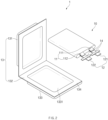
- FIG. 2 is an assembly view of the pouch type secondary battery 1 according to an embodiment of the present invention.
- the pouch-type secondary battery 1 may further include: a plurality of electrode tabs 11 respectively protruding to sides from the cathode 101 and the anode 102 as well as the electrode assembly 10; a plurality of electrode leads 12 respectively connected to the electrode tabs 11 to transfer electricity generated in the electrode assembly 10 to the outside; a battery case 13 accommodating the electrode assembly 10 therein; and an insulation part 14 surrounding the electrode leads 12, sealed with the battery case 13, and containing the flame retardant.
- the electrode assembly 10 is inserted into the battery case 13 and sealed after injection of the electrolyte.
- the electrode assembly 10 includes the electrode tabs 11.
- the electrode tabs 11 are respectively connected to the cathode 101 and the anode 102 of the electrode assembly 10 to protrude to the outside of the electrode assembly 10, thereby providing a path, through which electrons move, between the inside and outside of the electrode assembly 10.
- the electrode collectors 1011 and 1021 of the electrode assembly 10 may include active material coating portions 1013 and 1023 coated with the electrode active materials 1012 and 1022 and active material non-coating portions 1014 and 1024 which are not coated with the electrode active materials 1012 and 1022.
- the electrode tab 11 may be formed by cutting the active material non-coating portions 1014 and 1024 or may be formed by connecting a separate conductive member to the active material non-coating portions 1014 and 1024 by ultrasonic welding. As illustrated in FIG. 2 , the electrode tabs 11 may protrude from one side of the electrode assembly 10 in the same direction, but the present invention is not limited thereto. For example, the electrode tabs 11 may protrude in directions different from each other.
- the electrode lead 12 is connected to the electrode tab 11 through spot welding. Also, a portion of the electrode lead 12 is surrounded by an insulation part 14.
- the insulation part 14 may be disposed to be limited within a sealing part 134, at which an upper case 131 and a lower case 132 of the battery case 13 are thermally fused, so that the electrode lead 12 is bonded to the battery case 13. Also, electricity generated from the electrode assembly 10 may be prevented from flowing to the battery case 13 through the electrode lead 12, and the sealing of the battery case 13 may be maintained.
- the insulation part 14 may be made of a nonconductor having non-conductivity, which is not electrically conductive.
- the present invention is not limited thereto.
- various members may be used as the insulation part 14 as long as the members are capable of insulating the electrode lead 12.
- the flame retardant may be further provided in the insulation part 14 according to an embodiment of the present invention. Therefore, the cells may be protected from the cause of ignition such as external fire, flame, spark, etc. to improve heat resistance stability of the secondary battery 1.
- the flame retardant is a material that inhibits combustion reaction and may include various flame retardants such as halogen-based flame retardants, phosphorus-based flame retardants, or inorganic compound flame retardants. This will be described below in detail.
- the electrode leads 12 may extend in the same direction or extend in directions different from each other according to the formation positions of the cathode tab 111 and the anode tab 112.
- the cathode lead 121 and the anode lead 122 may be made of materials different from each other. That is, the cathode lead 121 may be made of the same material as the cathode collector 1011, i.e., an aluminum (Al) material, and the anode lead 122 may be made of the same material as the anode collector 1021, i.e., a copper (Cu) material or a copper material coated with nickel (Ni). Also, a portion of the electrode lead 12, which protrudes to the outside of the battery case 13, may be provided as a terminal part and electrically connected to an external terminal.
- the battery case 13 may be a pouch made of a flexible material.
- the battery case 13 accommodates the electrode assembly 10 so that a portion of the electrode lead 12, i.e., the terminal part is exposed and then is sealed.
- the battery case 13 includes the upper case 131 and the lower case 132.
- a cup part 133 having an accommodation space 1331 accommodating the electrode assembly 10 is formed in the lower case 132, and the upper case 131 covers an upper portion of the accommodation space 1331 to prevent the electrode assembly 10 from being separated to the outside of the battery case 13.
- the cup part 133 having the accommodation part 1331 may be formed in the upper case 131 to accommodate the electrode assembly 10 in the upper portion.
- one side of the upper case 131 and one side of the lower case 132 may be connected to each other.
- the present invention is not limited thereto.
- the upper case 131 and the lower case 132 may be separately manufactured to be separated from each other.
- the electrode assembly 10 When the electrode lead 12 is connected to the electrode tab 11 of the electrode assembly 10, and the insulation part 14 is provided on a portion of the electrode lead 12, the electrode assembly 10 may be accommodated in the accommodation space 1331 provided in the lower case 132, and the upper pouch 131 may cover the upper side of the case space 1331. Also, when the electrolyte is injected, and the sealing part formed on the edge of each of the upper case 131 and the lower case 132 is sealed, the secondary battery 1 is manufactured.
- FIG. 3 is a plan view of the cathode 101 according to an embodiment of the present invention
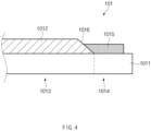
- FIG. 4 is a partial enlarged view of the cathode active material coating portion 1013 and the cathode active material non-coating portion 1014 of the cathode 101 according to an embodiment of the present invention.
- the coating portion 1015 and 1025a containing the flame retardant is coated between the active material coating portions 1013 and 1023 and the active material non-coating portions 1014 and 1024 of the electrodes 101 and 102, even though the cathode 101 and the anode 102 directly contact each other, the initial heat generation may be suppressed to secure safety.
- the electrodes 101 and 102 includes: the active material coating portions 1013 and 1023 coated with the electrode active materials 1012 and 1022 on at least one surface of the electrode collectors 1011 and 1021; the active material non-coating portions 1014 and 1024 formed on sides of the active material coating portions 1013 and 1023 and are not coated with the electrode active materials 1012 and 1022; and a coating portion 1015 and 1025a coated between the active material coating portions 1013 and 1023 and the active material non-coating portions 1014 and 1024 and containing the flame retardant.
- the electrode assembly includes the cathode 101 including a cathode active material coating portion 1013 coated with the cathode active material 1012 on at least one surface of the cathode collector 1011, a cathode active material non-coating portion 1014 which is formed on one side of the cathode active material coating portion 1013 and is not coated with the cathode active material 1012, and a cathode coating portion 1015 coated between the cathode active material coating portion 1013 and the cathode active material non-coating portion 1014 and containing the flame retardant; the anode 102 including an anode active material coating portion 1023 coated with the anode active material 1022 on at least one surface of the anode collector 1021, an anode active material non-coating portion 1024 which is formed on one side of the anode active material coating portion 1023 and is not coated with the anode active material 1022; and the separator disposed between the cathode 101 and the an
- the cathode active material coating portion 1013 is a portion that is coated with the cathode active material 1012 on at least one surface of the cathode collector 1011. As illustrated in FIG. 3 , the cathode active material coating portion 1013 is a portion on which the cathode active material 1012 is applied to the cathode collector 1011.
- the conductive agent and the binder may be mixed with the cathode active material 1012.
- the cathode active material non-coating portion 1014 is a portion which is formed on one side of the cathode active material coating portion 1013 in the cathode 101 and is not coated with the cathode active material 1012. As described above, the cathode tab 111 may be formed by cutting the cathode active material non-coating portion 1014 or by connecting a separate conductive member. Since the cathode active material non-coating portion 1014 is formed on the one side of the cathode active material coating portion 1013, as illustrated in FIG. 4 , the cathode active material non-coating portion 1014 may be formed on the same surface of the cathode collector 1011.
- the secondary battery 1 While the secondary battery 1 is actually used, an accident due to collision with the outside may occur. For example, a sharp object may pass through the secondary battery 1, and thus, the cathode 101 and the anode 102 may directly contact each other to cause the short circuit. Due to the short circuit, a large amount of gas may be generated at a high speed in a short time, and a high temperature rise may occur. Furthermore, large explosion may occur to lead to a major accident.
- the contact between the cathode 101 and the anode 102 may include four cases such as a case in which the cathode collector 1011 and the anode collector 1021 contact each other, a case in which the cathode collector 1011 and the anode active material 1022 contact each other, a case in which the cathode active material 1012 and the anode collector 1021 contact each other, and a case in which the cathode active material 1012 and the anode active material 1022 contact each other.
- the cathode 101 includes the cathode coating portion 1015 coated between the cathode active material coating portion 1013 and the cathode active material non-coating portion 1014 and containing the flame retardant.
- the flame retardant is a material that inhibits combustion reaction and may include various flame retardants such as halogen-based flame retardants, phosphorus-based flame retardants, or inorganic compound flame retardants.
- the halogen-based flame retardants generally exhibit a flame retardant effect by substantially stabilizing radicals occurring in a gas phase.
- the halogen-based flame retardants include, for example, tribromo phenoxyethane, tetra bromo bisphenol-A (TBBA), octabromo diphenyl ether (OBDPE), brominated epoxy oligomers, brominated polycarbonate oligomers, chlorinated paraffins, chlorinated polyethylene, alicyclic group chlorine-based flame retardants, and the like.
- the phosphorus-based flame retardants generally produce polymethic acid by pyrolysis to form a protection layer or blocks oxygen by using a carbon film produced by dehydration when polymethic acid is produced to exert the flame retardant effect.
- the flame retardants include, for example, phosphates such as red phosphorous, ammonium phosphate, and the like, phosphine oxide, phosphine oxide diols, phosphites, phosphonates, triaryl phosphate, alkyldiaryl phosphate, trialkyl phosphate, resorcinaol bisdiphenyl phosphate (RDP), and the like.
- the inorganic compound flame retardants are generally decomposed by heat to release water, carbon dioxide, sulfur dioxide, and incombustible gases such as hydrogen chloride and the like, thereby causing an endothermic reaction.
- the combustible gases may be diluted to prevent access of oxygen, and the inorganic compound flame retardants are cooled to reduce the production of the product to exert a flame retardant effect.
- the inorganic compound flame retardants include, for example, aluminum hydroxide (Al(OH) 3 ), magnesium hydroxide (Mg(OH) 2 ), boric acid (BH 3 O 3 ), antimony oxide, tin hydroxide, tin oxide, molybdenum oxide, zirconium compound, borate, calcium salts, and the like.
- an inorganic compound flame retardant among the said flame retardants may be preferably used.
- the flame retardant is contained in the cathode coating part 1015.
- flame retardant may preferably include aluminum hydroxide (Al(OH) 3 ), magnesium hydroxide (Mg(OH) 2 ), or boric acid (BH 3 O 3 ) that is an inorganic compound flame retardant.
- Al(OH) 3 aluminum hydroxide
- Mg(OH) 2 magnesium hydroxide
- boric acid BH 3 O 3
- other additives that induce a flame retardant synergistic effect when used to be mixed with the above-described flame retardant may be further provided.
- the cathode coating portion 1015 may be coated between the cathode active material coating portion 1013 and the cathode active material non-coating portion 1014 to suppress the initial heat generation even when the cathode collector 1011 and the anode active material 1022 directly contact with each other, thereby securing the safety.
- the cathode coating portion 1015 is coated to provide an interface 1016 between the cathode active material coating portion 1013 and the cathode active material non-coating portion 1014. That is, when the cathode active material 1012 is first applied to the cathode active material coating portion 1013, one end of the cathode active material 1012 has the interface 1016 between the cathode active material coating portion 1013 and the cathode active material non-coating portion 1014. Then, the cathode coating portion 1015 may be coated while partially covering the one end of the applied cathode active material 1012.
- the cathode collector 1011 of the cathode active material non-coating portion 1014 may not be significantly exposed.
- the cathode collector 1011 and the anode active material 1022 may be prevented from contacting each other through the partially delaminated area of the cathode coating portion 1015.
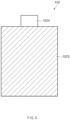
- FIG. 5 is a plan view of the anode 102 according to an embodiment of the present invention
- FIG. 6 is a partial enlarged view of the anode active material coating portion 1023 and the anode active material non-coating portion 1024 of the anode 102 according to an embodiment of the present invention.
- the anode active material coating portion 1023 is a portion that is coated with the anode active material 1022 on at least one surface of the anode collector 1021. As shown in FIG. 5 , the anode active material coating portion 1023 is a portion on which the anode active material 1022 is applied to the anode collector 1021.
- the conductive agent, the binder, and the filler may be optionally mixed with the anode active material 1022.
- the anode active material non-coating portion 1024 is a portion which is formed on one side of the anode active material coating portion 1023 in the anode 102 and is not coated with the anode active material 1022.
- the anode tab 112 may be formed by cutting the anode active material non-coating portion 1024 or by connecting a separate conductive member. Since the anode active material non-coating portion 1024 is formed on the one side of the anode active material coating portion 1023, as illustrated in FIG. 6 , the anode active material non-coating portion 1024 may be formed on the same surface of the anode collector 1021.
- the anode 102 does not have the anode coating portion containing the flame retardant.
- FIG. 7 is a plan view of an anode 102a according to another embodiment of the present invention
- FIG. 8 is a partial enlarged view of an anode active material coating portion 1023a and an anode active material non-coating portion 1024a of the anode 102a according to another embodiment of the present invention.
- anode collector 1021 contacts a cathode collector 1011 or a cathode active material 1012
- a risk of explosion is relatively small.
- this is only relative to the case in which the cathode collector 1011 and an anode active material 1022 contact each other, and also, safety is not secured.
- the anode 102a further includes an anode coating portion 1025a that is coated between the anode active material coating portion 1023a and the anode active material non-coating portion 1024a and contains a flame retardant.
- anode coating portion 1025a that is coated between the anode active material coating portion 1023a and the anode active material non-coating portion 1024a and contains a flame retardant.
- the anode coating portion 1025a may be coated to provide an interface 1026a between the anode active material coating portion 1023a and the anode active material non-coating portion 1024a. That is, when the anode active material 1022a is first applied to the anode active material coating portion 1023a, one end of the anode active material 1022a has the interface 1026a between the anode active material coating portion 1023a and the anode active material non-coating portion 1024a. Then, the anode coating portion 1025a may be coated while partially covering the one end of the applied anode active material 1022a.
- the anode collector 1021 of the anode active material non-coating portion 1024a may not be significantly exposed.
- the anode collector 1021 and the cathode collector 1011 or the cathode active material 1012 may be prevented from contacting each other through the partially delaminated area of the anode coating portion 1025a.
Landscapes
- Chemical & Material Sciences (AREA)
- Chemical Kinetics & Catalysis (AREA)
- Electrochemistry (AREA)
- General Chemical & Material Sciences (AREA)
- Engineering & Computer Science (AREA)
- Manufacturing & Machinery (AREA)
- Materials Engineering (AREA)
- Battery Electrode And Active Subsutance (AREA)
- Secondary Cells (AREA)
- Inorganic Chemistry (AREA)
Description
- The present application claims the benefit of the priority of
Korean Patent Application No. 10-2019-0007597, filed on January 21, 2019 - The present invention relates to an electrode and an electrode assembly, and more particularly, to an electrode in which initial heat generation is suppressed through heat absorption reaction of a flame retardant when an abnormal operation such as internal short circuit, external short circuit, overcharge, overdischarge, and the like occurs, thereby securing safety, and an electrode assembly.
- In general, secondary batteries include nickelcadmium batteries, nickel-hydrogen batteries, lithium ion batteries, and lithium ion polymer batteries. Such a secondary battery is being applied to and used in small-sized products such as digital cameras, P-DVDs, MP3Ps, mobile phones, PDAs, portable game devices, power tools, E-bikes, and the like as well as large-sized products requiring high power such as electric vehicles and hybrid vehicles, power storage devices for storing surplus power or renewable energy, and backup power storage devices.
- In order to manufacture an electrode assembly, a cathode, a separator, and an anode are manufactured and stacked. Specifically, cathode active material slurry is applied to a cathode collector, and anode active material slurry is applied to an anode collector to manufacture a cathode and an anode. Also, when the separator is interposed and stacked between the manufactured cathode and anode, unit cells are formed. The unit cells are stacked on each other to form an electrode assembly. Also, when the electrode assembly is accommodated in a specific case, and an electrolyte is injected, the secondary battery is manufactured.
-
KR20030042578A KR101595607B1 -
KR100956397B1 -
KR20130064031A -
KR20180043232A - However, in the related art, when an abnormal operation such as exposure of the secondary battery at a high temperature, internal/external short circuit, overcharging, or overdischarging occurs, the separator is contracted due to generated heat, and thus, the cathode and the anode directly contact each other to increase in possibility of occurrence of the short circuit. Also, the short circuit may occur due to the contact between the cathode and the anode due to poor battery production. Due to the short circuit, rapid electron transfer may occur inside the battery, and thus, when the heat generation and side reactions occur, the secondary battery may be exploded to cause a safety problem. In particular, when an electrical malfunction occurs, such as the overcharge, the overdischarge, or the external short circuit, since high current flows, and the thermal conductivity of the collector is low, the temperature of the collector is higher than that of the active material layer. Thereafter, the heat may be diffused, and thus, thermal, chemical, and electrochemical reactions of components such as the active materials and the electrolytes may be added to lead to thermal runaway.
- An object of the prevent invention is to provide an electrode in which short circuit due to contact between a cathode and an anode, which may occur when a battery is manufactured, is prevented when an abnormal operation such as internal short circuit, external short circuit, overcharge, overdischarge, and the like occurs, and simultaneously, initial heat generation is suppressed through heat absorption reaction of a flame retardant to secure safety, and an electrode assembly.
- The objects of the present invention are not limited to the aforementioned object, but other objects not described herein will be clearly understood by those skilled in the art from descriptions below.
- The invention is defined in the appended set of claims.
An electrode according to an embodiment of the present invention for solving the above problem includes: an active material coating portion coated with an electrode active material on at least one surface of an electrode collector; an active material non-coating portion which is formed on one side of the active material coating portion and is not coated with the electrode active material; and an electrode coating portion which is coated between the active material coating portion and the active material non-coating portion and contains a flame retardant. - Also, the electrode collector may be a cathode collector, and the electrode active material may be a cathode active material.
- Also, the flame retardant may include halogen-based flame retardants, phosphorus-based flame retardants, or inorganic compound flame retardants.
- Also, the flame retardant may include aluminum hydroxide (Al(OH)3), magnesium hydroxide (Mg(OH)2), or boric acid (BH3O3) .
- Also, the electrode coating portion includes an interface between the active material coating portion and the active material non-coating portion.
- Also, the active material coating portion and the active material non-coating portion may be formed on a same surface of the electrode collector.
- An electrode assembly according to an embodiment of the present invention for solving the above problem includes: a cathode including a cathode active material coating portion coated with a cathode active material on at least one surface of a cathode collector, a cathode active material non-coating portion which is formed on one side of the cathode active material coating portion and is not coated with the cathode active material, and a cathode coating portion which is coated between the cathode active material coating portion and the cathode active material non-coating portion and contains a flame retardant; an anode including an anode active material coating portion coated with an anode active material on at least one surface of an anode collector, an anode active material non-coating portion which is formed on one side of the anode active material coating portion and is not coated with the anode active material; and a separator disposed between the cathode and the anode.
- Also, the anode may further include an anode coating portion which is coated between the anode active material coating portion and the anode active material non-coating portion and contains a flame retardant.
- The present invention also provide a secondary battery including the electrode assembly.
- Also, the secondary battery may further include: a plurality of electrode tabs respectively protruding to sides from the cathode and the anode; a plurality of electrode leads respectively connected to the electrode tabs to transfer electricity generated in the electrode assembly to the outside; a battery case configured to accommodate the electrode assembly therein; and an insulation part configured to surround the electrode leads, sealed with the battery case, and containing a flame retardant.
- Particularities of other embodiments are included in the detailed description and drawings.
- The embodiments of the present invention may have at least the following effects.
- Since the non-conductive coating portion containing the flame retardant is coated between the active material coating portion and the active material non-coating portion, the short circuit between the cathode and the anode by the damage, the folding, and the like of the separator due to the defects and the abnormal operation of the battery when the battery is produced may be prevented.
- In addition, when the battery abnormally operates, the flame retardant may suppress the initial heat generation to secure the safety.
- The effects of the prevent invention are not limited by the aforementioned description, and thus, more varied effects are involved in this specification.
-
-
FIG. 1 is a schematic view of an electrode assembly according to an embodiment of the present invention. -
FIG. 2 is an assembly view of a pouch type secondary battery according to an embodiment of the present invention. -
FIG. 3 is a plan view of a cathode according to an embodiment of the present invention. -
FIG. 4 is a partial enlarged view of a cathode active material coating portion and a cathode active material non-coating portion of the cathode according to an embodiment of the present invention. -
FIG. 5 is a plan view of an anode according to an embodiment of the present invention. -
FIG. 6 is a partial enlarged view of an anode active material coating portion and an anode active material non-coating portion of the anode according to an embodiment of the present invention. -
FIG. 7 is a plan view of an anode according to another embodiment of the present invention. -
FIG. 8 is a partial enlarged view of an anode active material coating portion and an anode active material non-coating portion of the anode according to another embodiment of the present invention. - Advantages and features of the present invention, and implementation methods thereof will be clarified through following embodiments described with reference to the accompanying drawings. The present invention may, however be embodied in different forms and should not be construed as limited to the embodiments set forth herein. Rather, these embodiments are provided so that this disclosure will be thorough and complete, and will fully convey the scope of the present invention to those skilled in the art. Further, the present invention is only defined by scopes of claims. Like reference numerals refer to like elements throughout.
- Unless terms used in the present invention are defined differently, all terms (including technical and scientific terms) used herein have the same meaning as generally understood by those skilled in the art. Also, unless defined clearly and apparently in the description, the terms as defined in a commonly used dictionary are not ideally or excessively construed as having formal meaning.
- In the following description, the technical terms are used only for explaining a specific exemplary embodiment while not limiting the present invention. In this specification, the terms of a singular form may include plural forms unless specifically mentioned. The meaning of "comprises" and/or "including" does not exclude other components besides a mentioned component.
- Hereinafter, preferred embodiments will be described in detail with reference to the accompanying drawings.
-
FIG. 1 is a schematic view of anelectrode assembly 10 according to an embodiment of the present invention. - In a process of manufacturing the
electrode assembly 10 according to an embodiment of the present invention, as described above, first, slurry in which a cathodeactive material 1012, a binder, and a plasticizer are mixed is applied to acathode collector 1011, and slurry in which an anodeactive material 1022, the binder, and the plasticizer are mixed is applied to ananode collector 1021 to manufacture acathode 101 and ananode 102. Also, when aseparator 103 is disposed between the manufacturedcathode 101 and the manufacturedanode 102 so as to be stacked, unit cells are formed. Then, the unit cells are stacked on each other to form theelectrode assembly 10 having a predetermined shape as illustrated inFIG. 1 . - The
cathode 101 and theanode 102, which are used in the present invention, are not particularly limited to bothelectrodes active materials electrode collectors cathode 101 may be manufactured by, for example, applying the slurry, in which the cathodeactive material 1012, the conductive agent, and the binder are mixed, onto acathode collector 1011, and then drying and pressing the slurry. At this time, if necessary, the slurry may further include a filler. Thecathode 101 may be manufactured in a sheet shape and mounted on a roll. - The
cathode collector 1011 generally has a thickness of 3 um to 500 um. Thecathode collector 1011 is usually made of a material having high conductivity without causing a chemical change. Such a material may be surface-treated with, for example, stainless steel, aluminum, nickel, titanium, calcined carbon, or aluminum or stainless steel on which carbon, nickel, titanium, silver, or the like is surface-treated on a surface thereof, but is not limited thereto. In addition, thecathode collector 1011 may form a fine unevenness on a surface of thecathode collector 1012 to increase in adhesion of the cathodeactive material 1012. Also, thecathode collector 1011 may have various shapes such as a film, a sheet, a foil, a net, a porous body, a foam, or a non-woven fabric. - In case of a lithium secondary battery, the cathode active material 1012 includes, for example, a layered compound of lithium cobalt oxides (LiCoO2), lithium nickel oxides (LiNiO2), etc., or a compound substituted with one or more transition metals; lithium manganese oxides such as oxides represented by Chemical Formula of Li1+xMn2-xO4 (in which x is 0 to 0.33), LiMnO3, LiMn2O3, LiMnO2, etc.; lithium copper oxides (Li2CuO2); vanadium oxides such as LiV3O8, LiFe3O4, V2O5, Cu2V2O7, etc.; Ni site-type lithium nickel oxides represented by Chemical Formula of LiNi1-xMxO2 (in which M=Co, Mn, Al, Cu, Fe, Mg, B or Ga, x=0.01 to 0.3); lithium manganese complex oxides represented by Chemical Formula of LiMn2-xMxO2 (in which M=Co, Ni, Fe, Cr, Zn or Ta, and x=0.01 to 0.1) or Li2Mn3MO8 (in which, M=Fe, Co, Ni, Cu or Zn); 3-component lithium oxides represented by Chemical Formula of Li [Ni1-x-yCoxMy]O2(M = Mn or Al, and x, y = 0 to 1) ; 4-component lithium oxides represented by Chemical Formula of Li [Ni1-x-yCoxMnyAlz]O2(x, y, z = 0 to 1) ; LiMn2O4 in which a portion of Li in Chemical Formula is substituted with alkaline earth metal ions; disulfide compounds; Fe2(MoO4)3, and the like. However, this embodiment is not limited thereto.
- The conductive agent is generally added at 1% to about 50% by weight based on the total weight of the mixture including the cathode
active material 1012. The conductive agent is usually made of a material having conductivity without causing a chemical change. The conductive agent may include, for example, conductive materials such as: graphite such as natural graphite and artificial graphite; carbon black such as acetylene black, Ketjen black, channel black, furnace black, lamp black, and thermal black; conductive fiber such as carbon fiber and metal fiber; metal powder such as carbon fluorine, aluminum, and nickel powder; conductive whisker such as zinc oxide and potassium titanate; conductive oxide such as titanium oxide; or polyphenylene derivatives. - The binder is a component assisting the bonding of the active material to the conductive material and the bonding to the collector and is commonly added at 1 wt% to 50 wt% based on the total weight of the mixture including the cathode
active material 1012. Examples of the binder may include polyfluoro vinylidene, polyvinyl alcohol, carboxymethyl cellulose (CMC), starch, hydroxypropyl cellulose, regenerated cellulose, polyvinyl pyrrolidone, tetrafluoroethylene, polyethylene, polypropylene, ethylenepropylene-diene polymer (EPDM), sulfonated EPDM, styrene butadiene rubber, fluorine rubber, various copolymers, and the like. - The filler is optionally used as a component that inhibits expansion of the
cathode 101. And, a general filler may be used if the filler is a fibrous material without causing the chemical change. Examples of the filler may include olefin polymers such as polyethylene and polypropylene; and fibrous materials such as glass fibers and carbon fibers. - The
anode 102 may be manufactured by, for example, applying the anodeactive material 1022 on theanode collector 1021 and then drying and pressing the anodeactive material 1022. If necessary, the anodeactive material 1022 may optionally include a conductive agent, a binder, a filler, and the like. Theanode 102 may be manufactured in a sheet shape and mounted on a roll. - The
anode collector 1021 generally has a thickness of 3 um to 500 um. Theanode collector 1021 is usually made of a material having conductivity without causing a chemical change. Examples of the material include copper, stainless steel, aluminum, nickel, titanium, calcined carbon, copper or stainless steel on which carbon, nickel, titanium, silver, or the like is surface-treated on a surface thereof, or aluminum-cadmium alloys. In addition, theanode collector 1021 may form fine unevenness on the surface of theanode collector 1021 to increase in bonding force of the anodeactive material 1022. Also, theanode collector 1021 may have various shapes such as a film, a sheet, a foil, a net, a porous body, a foam, or a non-woven fabric. - The anode
active material 1022 may include, for example, carbon such as non-graphitizable carbon, graphite-based carbon, etc.; metal complex oxides such as LixFe2O3 (0≤ x≤1) , LixWO2 (0≤x≤1), SnxMe1-xMe'yOz (Me: Mn, Fe, Pb, Ge; Me': Al, B, P, Si, elements included in theGroup 1, Group 2 and Group 3 in the periodic table, halogen, where 0<x≤1; 1≤y≤3; 1≤z≤8), etc.; lithium metals; lithium alloys; silicon-based alloys; titanium compounds such as Li4Ti5O2; tin-based alloys; metal oxides such as MnOx, FeOx, CoOx, NiOx, CuOx, SnO, SnO2, PbO, PbO2, Pb2O3, Pb3O4, Sb2O3, Sb2O4, Sb2O5, GeO, GeO2, Bi2O3, Bi2O4, and Bi2O5; conductive polymers such as polyacetylene, etc.; Li-Co-Ni-based material, and the like. - Generally known polyolefin separators or a composite separators in which an organic or inorganic composite layer is formed on an olefin base material may be used as the separator that insulates the
electrodes cathode 101 and theanode 102, but is not particularly limited thereto. - According to an embodiment of the present invention, the
electrode assembly 10 having the above structure is accommodated in thebattery case 13, and then, the electrolyte is injected to manufacture thesecondary battery 1. -
FIG. 2 is an assembly view of the pouch typesecondary battery 1 according to an embodiment of the present invention. - The pouch-type
secondary battery 1 according to an embodiment of the present invention may further include: a plurality ofelectrode tabs 11 respectively protruding to sides from thecathode 101 and theanode 102 as well as theelectrode assembly 10; a plurality of electrode leads 12 respectively connected to theelectrode tabs 11 to transfer electricity generated in theelectrode assembly 10 to the outside; abattery case 13 accommodating theelectrode assembly 10 therein; and aninsulation part 14 surrounding the electrode leads 12, sealed with thebattery case 13, and containing the flame retardant. - In the process of manufacturing the
secondary battery 1, as described above, after forming theelectrode assembly 10, theelectrode assembly 10 is inserted into thebattery case 13 and sealed after injection of the electrolyte. - As illustrated in
FIG. 2 , theelectrode assembly 10 includes theelectrode tabs 11. Theelectrode tabs 11 are respectively connected to thecathode 101 and theanode 102 of theelectrode assembly 10 to protrude to the outside of theelectrode assembly 10, thereby providing a path, through which electrons move, between the inside and outside of theelectrode assembly 10. Theelectrode collectors electrode assembly 10 may include activematerial coating portions active materials material non-coating portions active materials electrode tab 11 may be formed by cutting the activematerial non-coating portions material non-coating portions FIG. 2 , theelectrode tabs 11 may protrude from one side of theelectrode assembly 10 in the same direction, but the present invention is not limited thereto. For example, theelectrode tabs 11 may protrude in directions different from each other. - In the
electrode assembly 10, theelectrode lead 12 is connected to theelectrode tab 11 through spot welding. Also, a portion of theelectrode lead 12 is surrounded by aninsulation part 14. Theinsulation part 14 may be disposed to be limited within a sealingpart 134, at which anupper case 131 and alower case 132 of thebattery case 13 are thermally fused, so that theelectrode lead 12 is bonded to thebattery case 13. Also, electricity generated from theelectrode assembly 10 may be prevented from flowing to thebattery case 13 through theelectrode lead 12, and the sealing of thebattery case 13 may be maintained. Thus, theinsulation part 14 may be made of a nonconductor having non-conductivity, which is not electrically conductive. In general, although an insulation tape which is easily attached to theelectrode lead 12 and has a relatively thin thickness is mainly used as theinsulation part 14, the present invention is not limited thereto. For example, various members may be used as theinsulation part 14 as long as the members are capable of insulating theelectrode lead 12. - Furthermore, the flame retardant may be further provided in the
insulation part 14 according to an embodiment of the present invention. Therefore, the cells may be protected from the cause of ignition such as external fire, flame, spark, etc. to improve heat resistance stability of thesecondary battery 1. The flame retardant is a material that inhibits combustion reaction and may include various flame retardants such as halogen-based flame retardants, phosphorus-based flame retardants, or inorganic compound flame retardants. This will be described below in detail. - The electrode leads 12 may extend in the same direction or extend in directions different from each other according to the formation positions of the
cathode tab 111 and theanode tab 112. Thecathode lead 121 and theanode lead 122 may be made of materials different from each other. That is, thecathode lead 121 may be made of the same material as thecathode collector 1011, i.e., an aluminum (Al) material, and theanode lead 122 may be made of the same material as theanode collector 1021, i.e., a copper (Cu) material or a copper material coated with nickel (Ni). Also, a portion of theelectrode lead 12, which protrudes to the outside of thebattery case 13, may be provided as a terminal part and electrically connected to an external terminal. - In the pouch type
secondary battery 1 according to an embodiment of the present invention, thebattery case 13 may be a pouch made of a flexible material. Hereinafter, the case in which thebattery case 13 is the pouch will be described. Thebattery case 13 accommodates theelectrode assembly 10 so that a portion of theelectrode lead 12, i.e., the terminal part is exposed and then is sealed. As illustrated inFIG. 2 , thebattery case 13 includes theupper case 131 and thelower case 132. Acup part 133 having anaccommodation space 1331 accommodating theelectrode assembly 10 is formed in thelower case 132, and theupper case 131 covers an upper portion of theaccommodation space 1331 to prevent theelectrode assembly 10 from being separated to the outside of thebattery case 13. Here, as illustrated inFIG. 2 , thecup part 133 having theaccommodation part 1331 may be formed in theupper case 131 to accommodate theelectrode assembly 10 in the upper portion. As illustrated inFIG. 2 , one side of theupper case 131 and one side of thelower case 132 may be connected to each other. However, the present invention is not limited thereto. For example, theupper case 131 and thelower case 132 may be separately manufactured to be separated from each other. - When the
electrode lead 12 is connected to theelectrode tab 11 of theelectrode assembly 10, and theinsulation part 14 is provided on a portion of theelectrode lead 12, theelectrode assembly 10 may be accommodated in theaccommodation space 1331 provided in thelower case 132, and theupper pouch 131 may cover the upper side of thecase space 1331. Also, when the electrolyte is injected, and the sealing part formed on the edge of each of theupper case 131 and thelower case 132 is sealed, thesecondary battery 1 is manufactured. -
FIG. 3 is a plan view of thecathode 101 according to an embodiment of the present invention, andFIG. 4 is a partial enlarged view of the cathode activematerial coating portion 1013 and the cathode activematerial non-coating portion 1014 of thecathode 101 according to an embodiment of the present invention. - According to an embodiment of the present invention, since the
coating portion material coating portions material non-coating portions electrodes cathode 101 and theanode 102 directly contact each other, the initial heat generation may be suppressed to secure safety. - Accordingly, the
electrodes material coating portions active materials electrode collectors material non-coating portions material coating portions active materials coating portion material coating portions material non-coating portions - Also, the electrode assembly according to an embodiment of the present invention includes the
cathode 101 including a cathode activematerial coating portion 1013 coated with the cathodeactive material 1012 on at least one surface of thecathode collector 1011, a cathode activematerial non-coating portion 1014 which is formed on one side of the cathode activematerial coating portion 1013 and is not coated with the cathodeactive material 1012, and acathode coating portion 1015 coated between the cathode activematerial coating portion 1013 and the cathode activematerial non-coating portion 1014 and containing the flame retardant; theanode 102 including an anode activematerial coating portion 1023 coated with the anodeactive material 1022 on at least one surface of theanode collector 1021, an anode activematerial non-coating portion 1024 which is formed on one side of the anode activematerial coating portion 1023 and is not coated with the anodeactive material 1022; and the separator disposed between thecathode 101 and theanode 102. - In the
cathode 101 of the plurality ofelectrodes electrode assembly 10, the cathode activematerial coating portion 1013 is a portion that is coated with the cathodeactive material 1012 on at least one surface of thecathode collector 1011. As illustrated inFIG. 3 , the cathode activematerial coating portion 1013 is a portion on which the cathodeactive material 1012 is applied to thecathode collector 1011. Here, as described above, the conductive agent and the binder may be mixed with the cathodeactive material 1012. - The cathode active
material non-coating portion 1014 is a portion which is formed on one side of the cathode activematerial coating portion 1013 in thecathode 101 and is not coated with the cathodeactive material 1012. As described above, thecathode tab 111 may be formed by cutting the cathode activematerial non-coating portion 1014 or by connecting a separate conductive member. Since the cathode activematerial non-coating portion 1014 is formed on the one side of the cathode activematerial coating portion 1013, as illustrated inFIG. 4 , the cathode activematerial non-coating portion 1014 may be formed on the same surface of thecathode collector 1011. - While the
secondary battery 1 is actually used, an accident due to collision with the outside may occur. For example, a sharp object may pass through thesecondary battery 1, and thus, thecathode 101 and theanode 102 may directly contact each other to cause the short circuit. Due to the short circuit, a large amount of gas may be generated at a high speed in a short time, and a high temperature rise may occur. Furthermore, large explosion may occur to lead to a major accident. In general, the contact between thecathode 101 and theanode 102 may include four cases such as a case in which thecathode collector 1011 and theanode collector 1021 contact each other, a case in which thecathode collector 1011 and the anodeactive material 1022 contact each other, a case in which the cathodeactive material 1012 and theanode collector 1021 contact each other, and a case in which the cathodeactive material 1012 and the anodeactive material 1022 contact each other. - Among them, generally, when the
cathode collector 1011 and the anodeactive material 1022 contact each other, an amount of generated heat is the highest to quickly reach the highest temperature, thereby maximally increasing in risk of explosion. Thus, the contact between thecathode collector 1011 and the anodeactive material 1022 is known as the most dangerous contact. Thus, according to an embodiment of the present invention, thecathode 101 includes thecathode coating portion 1015 coated between the cathode activematerial coating portion 1013 and the cathode activematerial non-coating portion 1014 and containing the flame retardant. - The flame retardant is a material that inhibits combustion reaction and may include various flame retardants such as halogen-based flame retardants, phosphorus-based flame retardants, or inorganic compound flame retardants.
- The halogen-based flame retardants generally exhibit a flame retardant effect by substantially stabilizing radicals occurring in a gas phase. The halogen-based flame retardants include, for example, tribromo phenoxyethane, tetra bromo bisphenol-A (TBBA), octabromo diphenyl ether (OBDPE), brominated epoxy oligomers, brominated polycarbonate oligomers, chlorinated paraffins, chlorinated polyethylene, alicyclic group chlorine-based flame retardants, and the like.
- The phosphorus-based flame retardants generally produce polymethic acid by pyrolysis to form a protection layer or blocks oxygen by using a carbon film produced by dehydration when polymethic acid is produced to exert the flame retardant effect. The flame retardants include, for example, phosphates such as red phosphorous, ammonium phosphate, and the like, phosphine oxide, phosphine oxide diols, phosphites, phosphonates, triaryl phosphate, alkyldiaryl phosphate, trialkyl phosphate, resorcinaol bisdiphenyl phosphate (RDP), and the like.
- The inorganic compound flame retardants are generally decomposed by heat to release water, carbon dioxide, sulfur dioxide, and incombustible gases such as hydrogen chloride and the like, thereby causing an endothermic reaction. As a result, the combustible gases may be diluted to prevent access of oxygen, and the inorganic compound flame retardants are cooled to reduce the production of the product to exert a flame retardant effect. The inorganic compound flame retardants include, for example, aluminum hydroxide (Al(OH)3), magnesium hydroxide (Mg(OH)2), boric acid (BH3O3), antimony oxide, tin hydroxide, tin oxide, molybdenum oxide, zirconium compound, borate, calcium salts, and the like.
- Particularly, an inorganic compound flame retardant among the said flame retardants may be preferably used. According to an embodiment of the present invention, the flame retardant is contained in the
cathode coating part 1015. Particularly, flame retardant may preferably include aluminum hydroxide (Al(OH)3), magnesium hydroxide (Mg(OH)2), or boric acid (BH3O3) that is an inorganic compound flame retardant. In some cases, other additives that induce a flame retardant synergistic effect when used to be mixed with the above-described flame retardant may be further provided. - The
cathode coating portion 1015 may be coated between the cathode activematerial coating portion 1013 and the cathode activematerial non-coating portion 1014 to suppress the initial heat generation even when thecathode collector 1011 and the anodeactive material 1022 directly contact with each other, thereby securing the safety. - In particular, as illustrated in
FIG. 4 , it is preferable that thecathode coating portion 1015 is coated to provide aninterface 1016 between the cathode activematerial coating portion 1013 and the cathode activematerial non-coating portion 1014. That is, when the cathodeactive material 1012 is first applied to the cathode activematerial coating portion 1013, one end of the cathodeactive material 1012 has theinterface 1016 between the cathode activematerial coating portion 1013 and the cathode activematerial non-coating portion 1014. Then, thecathode coating portion 1015 may be coated while partially covering the one end of the applied cathodeactive material 1012. Therefore, even if thecathode coating portion 1015 is delaminated to some extent, thecathode collector 1011 of the cathode activematerial non-coating portion 1014 may not be significantly exposed. As a result, thecathode collector 1011 and the anodeactive material 1022 may be prevented from contacting each other through the partially delaminated area of thecathode coating portion 1015. -
FIG. 5 is a plan view of theanode 102 according to an embodiment of the present invention, andFIG. 6 is a partial enlarged view of the anode activematerial coating portion 1023 and the anode activematerial non-coating portion 1024 of theanode 102 according to an embodiment of the present invention. - According to an embodiment of the present invention, in the
anode 102 of the plurality ofelectrodes electrode assembly 10, the anode activematerial coating portion 1023 is a portion that is coated with the anodeactive material 1022 on at least one surface of theanode collector 1021. As shown inFIG. 5 , the anode activematerial coating portion 1023 is a portion on which the anodeactive material 1022 is applied to theanode collector 1021. Here, as described above, the conductive agent, the binder, and the filler may be optionally mixed with the anodeactive material 1022. - The anode active
material non-coating portion 1024 is a portion which is formed on one side of the anode activematerial coating portion 1023 in theanode 102 and is not coated with the anodeactive material 1022. As described above, theanode tab 112 may be formed by cutting the anode activematerial non-coating portion 1024 or by connecting a separate conductive member. Since the anode activematerial non-coating portion 1024 is formed on the one side of the anode activematerial coating portion 1023, as illustrated inFIG. 6 , the anode activematerial non-coating portion 1024 may be formed on the same surface of theanode collector 1021. - As described above, since the risk of explosion is greatest when the
cathode collector 1011 and the anodeactive material 1022 contact each other, when theanode collector 1021 contacts thecathode collector 1011 or the cathodeactive material 1012, the risk of explosion is relatively small. Therefore, according to an embodiment of the present invention, theanode 102 does not have the anode coating portion containing the flame retardant. -
FIG. 7 is a plan view of ananode 102a according to another embodiment of the present invention, andFIG. 8 is a partial enlarged view of an anode activematerial coating portion 1023a and an anode activematerial non-coating portion 1024a of theanode 102a according to another embodiment of the present invention. - When an
anode collector 1021 contacts acathode collector 1011 or a cathodeactive material 1012, a risk of explosion is relatively small. However, this is only relative to the case in which thecathode collector 1011 and an anodeactive material 1022 contact each other, and also, safety is not secured. - Therefore, according to another embodiment of the present invention, as illustrated in
FIG. 7 , theanode 102a further includes ananode coating portion 1025a that is coated between the anode activematerial coating portion 1023a and the anode activematerial non-coating portion 1024a and contains a flame retardant. Thus, even when theanode collector 1021 and thecathode collector 1011 or the cathodeactive material 1012 directly contact each other, initial heat generation may be suppressed to ensure safety. - In particular, as illustrated in
FIG. 8 , theanode coating portion 1025a may be coated to provide aninterface 1026a between the anode activematerial coating portion 1023a and the anode activematerial non-coating portion 1024a. That is, when the anodeactive material 1022a is first applied to the anode activematerial coating portion 1023a, one end of the anodeactive material 1022a has theinterface 1026a between the anode activematerial coating portion 1023a and the anode activematerial non-coating portion 1024a. Then, theanode coating portion 1025a may be coated while partially covering the one end of the applied anodeactive material 1022a. Therefore, even if theanode coating portion 1025a is delaminated to some extent, theanode collector 1021 of the anode activematerial non-coating portion 1024a may not be significantly exposed. As a result, theanode collector 1021 and thecathode collector 1011 or the cathodeactive material 1012 may be prevented from contacting each other through the partially delaminated area of theanode coating portion 1025a.
Claims (9)
- An electrode comprising:an active material coating portion (1013; 1023) coated with an electrode active material (1012) on at least one surface of an electrode current collector (1011; 1021);an active material non-coating portion (1014; 1024) which is formed on one side of the active material coating portion (1013; 1023) and is not coated with the electrode active material; andan electrode coating portion (1015) which is coated between the active material coating portion and the active material non-coating portion (1014; 1024) and contains a flame retardant;wherein the electrode coating portion comprises an interface (1016) between the active material coating portion (1013; 1023) and the active material non-coating portion (1014; 1024) .
- The electrode of claim 1, wherein the electrode current collector (1011; 1021) is a cathode collector (1011), and
the electrode active material is a cathode active material (1012). - The electrode of claim 1, wherein the flame retardant comprises halogen-based flame retardants, phosphorus-based flame retardants, or inorganic compound flame retardants.
- The electrode of claim 3, wherein the flame retardant comprises aluminum hydroxide (Al(OH)3), magnesium hydroxide (Mg(OH)2), or boric acid (BH3O3).
- The electrode of claim 1, wherein the active material coating portion (1013) and the active material non-coating portion (1014; 1024) are formed on a same surface of the electrode current collector (1011; 1021).
- An electrode assembly (10) comprising:a cathode (101) comprising a cathode active material coating portion (1013) coated with a cathode active material (1012) on at least one surface of a cathode collector (1011), a cathode active material non-coating portion (1014; 1024) which is formed on one side of the cathode active material coating portion (1013) and is not coated with the cathode active material (1012), and a cathode coating portion (1015) which is coated between the cathode active material coating portion (1013) and the cathode active material non-coating portion (1014; 1024) and contains a flame retardant;an anode (102) comprising an anode active material coating portion (1023) coated with an anode active material (1022) on at least one surface of an anode collector (1021), an anode active material non-coating portion (1014; 1024) which is formed on one side of the anode active material coating portion (1023) and is not coated with the anode active material (1022); anda separator (103) disposed between the cathode (101) and the anode (102).
- The electrode assembly (10) of claim 6, wherein the anode (102) further comprises an anode coating portion (1025a) which is coated between the anode active material coating portion (1023) and the anode active material non-coating portion (1014; 1024) and contains a flame retardant.
- A secondary battery (1) comprising the electrode assembly (10) of claim 6.
- The secondary battery (1) of claim 6, further comprising:a plurality of electrode tabs (11) respectively protruding to sides from the cathode and the anode;a plurality of electrode leads (12) respectively connected to the electrode tabs (11) to transfer electricity generated in the electrode assembly (10) to the outside;a battery case (13) configured to accommodate the electrode assembly (10) therein; andan insulation part (14) configured to surround the electrode leads (12), sealed with the battery case (13), and containing a flame retardant.
Applications Claiming Priority (2)
| Application Number | Priority Date | Filing Date | Title |
|---|---|---|---|
| KR1020190007597A KR102366848B1 (en) | 2019-01-21 | 2019-01-21 | The Electrode And The Electrode Assembly |
| PCT/KR2019/017712 WO2020153604A1 (en) | 2019-01-21 | 2019-12-13 | Electrode and electrode assembly |
Publications (3)
| Publication Number | Publication Date |
|---|---|
| EP3761419A1 EP3761419A1 (en) | 2021-01-06 |
| EP3761419A4 EP3761419A4 (en) | 2021-04-28 |
| EP3761419B1 true EP3761419B1 (en) | 2024-06-12 |
Family
ID=71735826
Family Applications (1)
| Application Number | Title | Priority Date | Filing Date |
|---|---|---|---|
| EP19911595.7A Active EP3761419B1 (en) | 2019-01-21 | 2019-12-13 | Electrode and electrode assembly |
Country Status (9)
| Country | Link |
|---|---|
| US (1) | US12068482B2 (en) |
| EP (1) | EP3761419B1 (en) |
| JP (1) | JP7258398B2 (en) |
| KR (1) | KR102366848B1 (en) |
| CN (1) | CN111886726B (en) |
| ES (1) | ES2981861T3 (en) |
| HU (1) | HUE067141T2 (en) |
| PL (1) | PL3761419T3 (en) |
| WO (1) | WO2020153604A1 (en) |
Families Citing this family (5)
| Publication number | Priority date | Publication date | Assignee | Title |
|---|---|---|---|---|
| KR102824735B1 (en) * | 2020-11-02 | 2025-06-24 | 주식회사 엘지에너지솔루션 | Electrode with Excellent Weldability Between Electrode Lead and Electrode Tabs and Method for Manufacturing Same |
| US20220190346A1 (en) * | 2020-12-14 | 2022-06-16 | Global Graphene Group, Inc. | Lithium-protecting polymer composite layer for a lithium metal secondary battery and manufacturing method |
| CN215896624U (en) * | 2021-08-19 | 2022-02-22 | 宁德时代新能源科技股份有限公司 | Electrode assembly, battery monomer, battery and consumer |
| JP2024101616A (en) * | 2023-01-18 | 2024-07-30 | 三星エスディアイ株式会社 | Positive electrode for non-aqueous electrolyte secondary battery and non-aqueous electrolyte secondary battery |
| KR20250128491A (en) * | 2024-02-21 | 2025-08-28 | 주식회사 유앤에스에너지 | Current collector for electrode having fuse-integrated uncoated portion and secondary battery including the same |
Family Cites Families (18)
| Publication number | Priority date | Publication date | Assignee | Title |
|---|---|---|---|---|
| KR100449757B1 (en) * | 2001-11-23 | 2004-09-22 | 삼성에스디아이 주식회사 | Battery unit and secondary battery applying the such |
| KR100440933B1 (en) * | 2002-02-06 | 2004-07-21 | 삼성에스디아이 주식회사 | Battery unit and lithium polymer battery applying the same and the fabrication method thereof |
| JP4698929B2 (en) * | 2003-02-04 | 2011-06-08 | パナソニック株式会社 | Non-aqueous electrolyte secondary battery |
| KR20060034181A (en) | 2004-10-18 | 2006-04-21 | 주식회사 엘지화학 | Lithium secondary battery having frame retardant film |
| KR101045858B1 (en) | 2007-08-15 | 2011-07-01 | 주식회사 엘지화학 | Electrode lead containing high insulation lead film and secondary battery using the same |
| JP2009054484A (en) * | 2007-08-28 | 2009-03-12 | Seiko Epson Corp | All solid lithium secondary battery and its manufacturing method |
| KR101255628B1 (en) | 2009-02-17 | 2013-04-16 | 주식회사 엘지화학 | Method Of Manufacturing Battery Pack With Flexible Manufacturing Plan |
| US9099756B2 (en) | 2009-02-17 | 2015-08-04 | Samsung Sdi Co., Ltd. | Flame retardant electrolyte for rechargeable lithium battery and rechargeable lithium battery including the same |
| KR100956397B1 (en) | 2009-11-20 | 2010-05-06 | 주식회사 이아이지 | Poutch type battery and process for producing the same having sealing part coated with flame retardant and heat resistant resin composition with a combined flame retardant and heat resistant material in thermoplastic resin or in thermosetting resin |
| KR101595607B1 (en) * | 2011-12-07 | 2016-02-18 | 주식회사 엘지화학 | Secondary battery with improved safety |
| KR101991458B1 (en) | 2012-12-13 | 2019-06-20 | 에리 파워 가부시키가이샤 | Non-aqueous electrolytic solution secondary battery and method for producing non-aqueous electrolytic solution secondary battery |
| JP6093244B2 (en) | 2013-05-24 | 2017-03-08 | 富士機械工業株式会社 | Double-side coating system |
| KR20150014263A (en) | 2013-07-29 | 2015-02-06 | 주식회사 엘지화학 | Battery Having Improved Thermal Stability |
| JP6346820B2 (en) | 2014-08-04 | 2018-06-20 | 富士機械工業株式会社 | Coating equipment |
| KR20160133771A (en) * | 2015-05-13 | 2016-11-23 | 주식회사 엘지화학 | Electrode lead or aluminum pouch for secondary battery with improved thermal resistance and secondary battery comprising same |
| KR20170038405A (en) * | 2015-09-30 | 2017-04-07 | 주식회사 엘지화학 | Secondary battery |
| JP7060008B2 (en) | 2017-03-13 | 2022-04-26 | 株式会社Gsユアサ | Electrodes and power storage elements |
| KR101930487B1 (en) | 2018-04-19 | 2018-12-18 | 주식회사 엘지화학 | Electrode lead or aluminum pouch for secondary battery with improved thermal resistance and secondary battery comprising same |
-
2019
- 2019-01-21 KR KR1020190007597A patent/KR102366848B1/en active Active
- 2019-12-13 CN CN201980020226.9A patent/CN111886726B/en active Active
- 2019-12-13 HU HUE19911595A patent/HUE067141T2/en unknown
- 2019-12-13 EP EP19911595.7A patent/EP3761419B1/en active Active
- 2019-12-13 JP JP2020567520A patent/JP7258398B2/en active Active
- 2019-12-13 WO PCT/KR2019/017712 patent/WO2020153604A1/en not_active Ceased
- 2019-12-13 ES ES19911595T patent/ES2981861T3/en active Active
- 2019-12-13 PL PL19911595.7T patent/PL3761419T3/en unknown
- 2019-12-13 US US16/978,059 patent/US12068482B2/en active Active
Also Published As
| Publication number | Publication date |
|---|---|
| WO2020153604A1 (en) | 2020-07-30 |
| KR20200090496A (en) | 2020-07-29 |
| EP3761419A4 (en) | 2021-04-28 |
| US12068482B2 (en) | 2024-08-20 |
| ES2981861T3 (en) | 2024-10-10 |
| JP2021526301A (en) | 2021-09-30 |
| CN111886726B (en) | 2023-10-24 |
| CN111886726A (en) | 2020-11-03 |
| HUE067141T2 (en) | 2024-10-28 |
| PL3761419T3 (en) | 2024-08-19 |
| JP7258398B2 (en) | 2023-04-17 |
| KR102366848B1 (en) | 2022-02-24 |
| EP3761419A1 (en) | 2021-01-06 |
| US20200411865A1 (en) | 2020-12-31 |
Similar Documents
| Publication | Publication Date | Title |
|---|---|---|
| EP3761419B1 (en) | Electrode and electrode assembly | |
| JP7130122B2 (en) | All-solid-state battery using lithium metal as the negative electrode | |
| US10256443B2 (en) | Battery pack, electric power tool, and electronic apparatus | |
| KR101833540B1 (en) | Battery Cell Having Means For Venting The Gas | |
| EP3327854B1 (en) | Battery cell including electrode lead containing gas adsorbent | |
| KR101418643B1 (en) | Electrode assembly comprising separator for improving safety and lithium secondary batteries comprising the same | |
| CN110073518B (en) | Secondary battery, battery pack, electric vehicle, power storage system, electric power tool, and electronic device | |
| KR101608631B1 (en) | Lithium Secondary Battery having Electrode Terminal Comprising Wood's Metal | |
| KR101794939B1 (en) | Battery Cell Comprising Electrode Assemblies of Different Size and Method for Preparing the Same | |
| KR20150125263A (en) | Sealing Device For Battery Case And Battery Cell Manufactured Using The Same | |
| CN110720149A (en) | Secondary battery, battery pack, electric vehicle, power storage system, electric power tool, and electronic device | |
| KR101640889B1 (en) | Lithium ion secondary battery cell and module comprising phase change material | |
| CN105684206A (en) | Lithium ion secondary battery | |
| JP5010250B2 (en) | Battery stack and battery pack | |
| KR101520148B1 (en) | Secondary battery comprising apparatus for preventing overcharge | |
| KR20140013177A (en) | Secondary battery and electrochemical cell having the same | |
| US20250118754A1 (en) | Negative electrode for secondary battery, and secondary battery | |
| KR102754586B1 (en) | The Electrode And The Electrode Assembly | |
| KR20220014767A (en) | The Electrode, The Electrode Assembly And The Secondary Battery | |
| JP7613476B2 (en) | Secondary battery | |
| CN119072812A (en) | Cylindrical lithium secondary battery | |
| KR101798929B1 (en) | Battery Case Having Label for Reinforcement and Secondary Battery Comprising the Same | |
| KR102904505B1 (en) | Electrode assembly and Secondary Battery comprising electrode assembly | |
| US20250112324A1 (en) | Battery and battery pack | |
| KR102939679B1 (en) | Secondary battery and device including the same |
Legal Events
| Date | Code | Title | Description |
|---|---|---|---|
| STAA | Information on the status of an ep patent application or granted ep patent |
Free format text: STATUS: THE INTERNATIONAL PUBLICATION HAS BEEN MADE |
|
| PUAI | Public reference made under article 153(3) epc to a published international application that has entered the european phase |
Free format text: ORIGINAL CODE: 0009012 |
|
| STAA | Information on the status of an ep patent application or granted ep patent |
Free format text: STATUS: REQUEST FOR EXAMINATION WAS MADE |
|
| 17P | Request for examination filed |
Effective date: 20200930 |
|
| AK | Designated contracting states |
Kind code of ref document: A1 Designated state(s): AL AT BE BG CH CY CZ DE DK EE ES FI FR GB GR HR HU IE IS IT LI LT LU LV MC MK MT NL NO PL PT RO RS SE SI SK SM TR |
|
| AX | Request for extension of the european patent |
Extension state: BA ME |
|
| REG | Reference to a national code |
Ref country code: DE Ref legal event code: R079 Free format text: PREVIOUS MAIN CLASS: H01M0004620000 Ipc: H01M0004130000 Ref country code: DE Ref legal event code: R079 Ref document number: 602019053768 Country of ref document: DE Free format text: PREVIOUS MAIN CLASS: H01M0004620000 Ipc: H01M0004130000 |
|
| A4 | Supplementary search report drawn up and despatched |
Effective date: 20210330 |
|
| RIC1 | Information provided on ipc code assigned before grant |
Ipc: H01M 4/13 20100101AFI20210324BHEP Ipc: H01M 10/058 20100101ALI20210324BHEP Ipc: H01M 10/052 20100101ALI20210324BHEP Ipc: H01M 4/62 20060101ALI20210324BHEP |
|
| RAP1 | Party data changed (applicant data changed or rights of an application transferred) |
Owner name: LG ENERGY SOLUTION LTD. |
|
| RAP3 | Party data changed (applicant data changed or rights of an application transferred) |
Owner name: LG ENERGY SOLUTION, LTD. |
|
| DAV | Request for validation of the european patent (deleted) | ||
| DAX | Request for extension of the european patent (deleted) | ||
| GRAP | Despatch of communication of intention to grant a patent |
Free format text: ORIGINAL CODE: EPIDOSNIGR1 |
|
| STAA | Information on the status of an ep patent application or granted ep patent |
Free format text: STATUS: GRANT OF PATENT IS INTENDED |
|
| INTG | Intention to grant announced |
Effective date: 20240325 |
|
| GRAS | Grant fee paid |
Free format text: ORIGINAL CODE: EPIDOSNIGR3 |
|
| GRAA | (expected) grant |
Free format text: ORIGINAL CODE: 0009210 |
|
| STAA | Information on the status of an ep patent application or granted ep patent |
Free format text: STATUS: THE PATENT HAS BEEN GRANTED |
|
| P01 | Opt-out of the competence of the unified patent court (upc) registered |
Effective date: 20240404 |
|
| AK | Designated contracting states |
Kind code of ref document: B1 Designated state(s): AL AT BE BG CH CY CZ DE DK EE ES FI FR GB GR HR HU IE IS IT LI LT LU LV MC MK MT NL NO PL PT RO RS SE SI SK SM TR |
|
| REG | Reference to a national code |
Ref country code: GB Ref legal event code: FG4D |
|
| REG | Reference to a national code |
Ref country code: CH Ref legal event code: EP |
|
| REG | Reference to a national code |
Ref country code: IE Ref legal event code: FG4D |
|
| REG | Reference to a national code |
Ref country code: DE Ref legal event code: R096 Ref document number: 602019053768 Country of ref document: DE |
|
| REG | Reference to a national code |
Ref country code: SE Ref legal event code: TRGR |
|
| PG25 | Lapsed in a contracting state [announced via postgrant information from national office to epo] |
Ref country code: BG Free format text: LAPSE BECAUSE OF FAILURE TO SUBMIT A TRANSLATION OF THE DESCRIPTION OR TO PAY THE FEE WITHIN THE PRESCRIBED TIME-LIMIT Effective date: 20240612 |
|
| PG25 | Lapsed in a contracting state [announced via postgrant information from national office to epo] |
Ref country code: FI Free format text: LAPSE BECAUSE OF FAILURE TO SUBMIT A TRANSLATION OF THE DESCRIPTION OR TO PAY THE FEE WITHIN THE PRESCRIBED TIME-LIMIT Effective date: 20240612 Ref country code: HR Free format text: LAPSE BECAUSE OF FAILURE TO SUBMIT A TRANSLATION OF THE DESCRIPTION OR TO PAY THE FEE WITHIN THE PRESCRIBED TIME-LIMIT Effective date: 20240612 |
|
| REG | Reference to a national code |
Ref country code: LT Ref legal event code: MG9D Ref country code: ES Ref legal event code: FG2A Ref document number: 2981861 Country of ref document: ES Kind code of ref document: T3 Effective date: 20241010 |
|
| PG25 | Lapsed in a contracting state [announced via postgrant information from national office to epo] |
Ref country code: GR Free format text: LAPSE BECAUSE OF FAILURE TO SUBMIT A TRANSLATION OF THE DESCRIPTION OR TO PAY THE FEE WITHIN THE PRESCRIBED TIME-LIMIT Effective date: 20240913 |
|
| REG | Reference to a national code |
Ref country code: NL Ref legal event code: MP Effective date: 20240612 |
|
| REG | Reference to a national code |
Ref country code: HU Ref legal event code: AG4A Ref document number: E067141 Country of ref document: HU |
|
| PG25 | Lapsed in a contracting state [announced via postgrant information from national office to epo] |
Ref country code: LV Free format text: LAPSE BECAUSE OF FAILURE TO SUBMIT A TRANSLATION OF THE DESCRIPTION OR TO PAY THE FEE WITHIN THE PRESCRIBED TIME-LIMIT Effective date: 20240612 |
|
| PG25 | Lapsed in a contracting state [announced via postgrant information from national office to epo] |
Ref country code: NO Free format text: LAPSE BECAUSE OF FAILURE TO SUBMIT A TRANSLATION OF THE DESCRIPTION OR TO PAY THE FEE WITHIN THE PRESCRIBED TIME-LIMIT Effective date: 20240912 Ref country code: LV Free format text: LAPSE BECAUSE OF FAILURE TO SUBMIT A TRANSLATION OF THE DESCRIPTION OR TO PAY THE FEE WITHIN THE PRESCRIBED TIME-LIMIT Effective date: 20240612 Ref country code: HR Free format text: LAPSE BECAUSE OF FAILURE TO SUBMIT A TRANSLATION OF THE DESCRIPTION OR TO PAY THE FEE WITHIN THE PRESCRIBED TIME-LIMIT Effective date: 20240612 Ref country code: GR Free format text: LAPSE BECAUSE OF FAILURE TO SUBMIT A TRANSLATION OF THE DESCRIPTION OR TO PAY THE FEE WITHIN THE PRESCRIBED TIME-LIMIT Effective date: 20240913 Ref country code: FI Free format text: LAPSE BECAUSE OF FAILURE TO SUBMIT A TRANSLATION OF THE DESCRIPTION OR TO PAY THE FEE WITHIN THE PRESCRIBED TIME-LIMIT Effective date: 20240612 Ref country code: BG Free format text: LAPSE BECAUSE OF FAILURE TO SUBMIT A TRANSLATION OF THE DESCRIPTION OR TO PAY THE FEE WITHIN THE PRESCRIBED TIME-LIMIT Effective date: 20240612 Ref country code: RS Free format text: LAPSE BECAUSE OF FAILURE TO SUBMIT A TRANSLATION OF THE DESCRIPTION OR TO PAY THE FEE WITHIN THE PRESCRIBED TIME-LIMIT Effective date: 20240912 |
|
| PG25 | Lapsed in a contracting state [announced via postgrant information from national office to epo] |
Ref country code: NL Free format text: LAPSE BECAUSE OF FAILURE TO SUBMIT A TRANSLATION OF THE DESCRIPTION OR TO PAY THE FEE WITHIN THE PRESCRIBED TIME-LIMIT Effective date: 20240612 |
|
| REG | Reference to a national code |
Ref country code: AT Ref legal event code: MK05 Ref document number: 1694979 Country of ref document: AT Kind code of ref document: T Effective date: 20240612 |
|
| PG25 | Lapsed in a contracting state [announced via postgrant information from national office to epo] |
Ref country code: NL Free format text: LAPSE BECAUSE OF FAILURE TO SUBMIT A TRANSLATION OF THE DESCRIPTION OR TO PAY THE FEE WITHIN THE PRESCRIBED TIME-LIMIT Effective date: 20240612 |
|
| PG25 | Lapsed in a contracting state [announced via postgrant information from national office to epo] |
Ref country code: PT Free format text: LAPSE BECAUSE OF FAILURE TO SUBMIT A TRANSLATION OF THE DESCRIPTION OR TO PAY THE FEE WITHIN THE PRESCRIBED TIME-LIMIT Effective date: 20241014 |
|
| PG25 | Lapsed in a contracting state [announced via postgrant information from national office to epo] |
Ref country code: PT Free format text: LAPSE BECAUSE OF FAILURE TO SUBMIT A TRANSLATION OF THE DESCRIPTION OR TO PAY THE FEE WITHIN THE PRESCRIBED TIME-LIMIT Effective date: 20241014 |
|
| PG25 | Lapsed in a contracting state [announced via postgrant information from national office to epo] |
Ref country code: EE Free format text: LAPSE BECAUSE OF FAILURE TO SUBMIT A TRANSLATION OF THE DESCRIPTION OR TO PAY THE FEE WITHIN THE PRESCRIBED TIME-LIMIT Effective date: 20240612 |
|
| PG25 | Lapsed in a contracting state [announced via postgrant information from national office to epo] |
Ref country code: IS Free format text: LAPSE BECAUSE OF FAILURE TO SUBMIT A TRANSLATION OF THE DESCRIPTION OR TO PAY THE FEE WITHIN THE PRESCRIBED TIME-LIMIT Effective date: 20241012 Ref country code: AT Free format text: LAPSE BECAUSE OF FAILURE TO SUBMIT A TRANSLATION OF THE DESCRIPTION OR TO PAY THE FEE WITHIN THE PRESCRIBED TIME-LIMIT Effective date: 20240612 |
|
| PG25 | Lapsed in a contracting state [announced via postgrant information from national office to epo] |
Ref country code: CZ Free format text: LAPSE BECAUSE OF FAILURE TO SUBMIT A TRANSLATION OF THE DESCRIPTION OR TO PAY THE FEE WITHIN THE PRESCRIBED TIME-LIMIT Effective date: 20240612 |
|
| PG25 | Lapsed in a contracting state [announced via postgrant information from national office to epo] |
Ref country code: SK Free format text: LAPSE BECAUSE OF FAILURE TO SUBMIT A TRANSLATION OF THE DESCRIPTION OR TO PAY THE FEE WITHIN THE PRESCRIBED TIME-LIMIT Effective date: 20240612 Ref country code: RO Free format text: LAPSE BECAUSE OF FAILURE TO SUBMIT A TRANSLATION OF THE DESCRIPTION OR TO PAY THE FEE WITHIN THE PRESCRIBED TIME-LIMIT Effective date: 20240612 |
|
| PG25 | Lapsed in a contracting state [announced via postgrant information from national office to epo] |
Ref country code: SM Free format text: LAPSE BECAUSE OF FAILURE TO SUBMIT A TRANSLATION OF THE DESCRIPTION OR TO PAY THE FEE WITHIN THE PRESCRIBED TIME-LIMIT Effective date: 20240612 |
|
| PG25 | Lapsed in a contracting state [announced via postgrant information from national office to epo] |
Ref country code: SM Free format text: LAPSE BECAUSE OF FAILURE TO SUBMIT A TRANSLATION OF THE DESCRIPTION OR TO PAY THE FEE WITHIN THE PRESCRIBED TIME-LIMIT Effective date: 20240612 Ref country code: SK Free format text: LAPSE BECAUSE OF FAILURE TO SUBMIT A TRANSLATION OF THE DESCRIPTION OR TO PAY THE FEE WITHIN THE PRESCRIBED TIME-LIMIT Effective date: 20240612 Ref country code: RO Free format text: LAPSE BECAUSE OF FAILURE TO SUBMIT A TRANSLATION OF THE DESCRIPTION OR TO PAY THE FEE WITHIN THE PRESCRIBED TIME-LIMIT Effective date: 20240612 Ref country code: IS Free format text: LAPSE BECAUSE OF FAILURE TO SUBMIT A TRANSLATION OF THE DESCRIPTION OR TO PAY THE FEE WITHIN THE PRESCRIBED TIME-LIMIT Effective date: 20241012 Ref country code: EE Free format text: LAPSE BECAUSE OF FAILURE TO SUBMIT A TRANSLATION OF THE DESCRIPTION OR TO PAY THE FEE WITHIN THE PRESCRIBED TIME-LIMIT Effective date: 20240612 Ref country code: CZ Free format text: LAPSE BECAUSE OF FAILURE TO SUBMIT A TRANSLATION OF THE DESCRIPTION OR TO PAY THE FEE WITHIN THE PRESCRIBED TIME-LIMIT Effective date: 20240612 Ref country code: AT Free format text: LAPSE BECAUSE OF FAILURE TO SUBMIT A TRANSLATION OF THE DESCRIPTION OR TO PAY THE FEE WITHIN THE PRESCRIBED TIME-LIMIT Effective date: 20240612 |
|
| PG25 | Lapsed in a contracting state [announced via postgrant information from national office to epo] |
Ref country code: IT Free format text: LAPSE BECAUSE OF FAILURE TO SUBMIT A TRANSLATION OF THE DESCRIPTION OR TO PAY THE FEE WITHIN THE PRESCRIBED TIME-LIMIT Effective date: 20240612 |
|
| REG | Reference to a national code |
Ref country code: DE Ref legal event code: R097 Ref document number: 602019053768 Country of ref document: DE |
|
| PG25 | Lapsed in a contracting state [announced via postgrant information from national office to epo] |
Ref country code: DK Free format text: LAPSE BECAUSE OF FAILURE TO SUBMIT A TRANSLATION OF THE DESCRIPTION OR TO PAY THE FEE WITHIN THE PRESCRIBED TIME-LIMIT Effective date: 20240612 |
|
| PLBE | No opposition filed within time limit |
Free format text: ORIGINAL CODE: 0009261 |
|
| STAA | Information on the status of an ep patent application or granted ep patent |
Free format text: STATUS: NO OPPOSITION FILED WITHIN TIME LIMIT |
|
| 26N | No opposition filed |
Effective date: 20250313 |
|
| PG25 | Lapsed in a contracting state [announced via postgrant information from national office to epo] |
Ref country code: MC Free format text: LAPSE BECAUSE OF FAILURE TO SUBMIT A TRANSLATION OF THE DESCRIPTION OR TO PAY THE FEE WITHIN THE PRESCRIBED TIME-LIMIT Effective date: 20240612 |
|
| REG | Reference to a national code |
Ref country code: CH Ref legal event code: PL |
|
| PG25 | Lapsed in a contracting state [announced via postgrant information from national office to epo] |
Ref country code: LU Free format text: LAPSE BECAUSE OF NON-PAYMENT OF DUE FEES Effective date: 20241213 |
|
| PG25 | Lapsed in a contracting state [announced via postgrant information from national office to epo] |
Ref country code: CH Free format text: LAPSE BECAUSE OF NON-PAYMENT OF DUE FEES Effective date: 20241231 |
|
| PG25 | Lapsed in a contracting state [announced via postgrant information from national office to epo] |
Ref country code: IE Free format text: LAPSE BECAUSE OF NON-PAYMENT OF DUE FEES Effective date: 20241213 |
|
| PGFP | Annual fee paid to national office [announced via postgrant information from national office to epo] |
Ref country code: DE Payment date: 20251120 Year of fee payment: 7 |
|
| PGFP | Annual fee paid to national office [announced via postgrant information from national office to epo] |
Ref country code: GB Payment date: 20251120 Year of fee payment: 7 |
|
| PGFP | Annual fee paid to national office [announced via postgrant information from national office to epo] |
Ref country code: HU Payment date: 20251216 Year of fee payment: 7 Ref country code: FR Payment date: 20251125 Year of fee payment: 7 |
|
| PGFP | Annual fee paid to national office [announced via postgrant information from national office to epo] |
Ref country code: BE Payment date: 20251120 Year of fee payment: 7 |
|
| PGFP | Annual fee paid to national office [announced via postgrant information from national office to epo] |
Ref country code: SE Payment date: 20251121 Year of fee payment: 7 |
|
| PGFP | Annual fee paid to national office [announced via postgrant information from national office to epo] |
Ref country code: PL Payment date: 20251124 Year of fee payment: 7 |
|
| PGFP | Annual fee paid to national office [announced via postgrant information from national office to epo] |
Ref country code: ES Payment date: 20260122 Year of fee payment: 7 |