EP3761125A1 - Ensuring data consistency between a modular device and an external system - Google Patents
Ensuring data consistency between a modular device and an external system Download PDFInfo
- Publication number
- EP3761125A1 EP3761125A1 EP20183736.6A EP20183736A EP3761125A1 EP 3761125 A1 EP3761125 A1 EP 3761125A1 EP 20183736 A EP20183736 A EP 20183736A EP 3761125 A1 EP3761125 A1 EP 3761125A1
- Authority
- EP
- European Patent Office
- Prior art keywords
- configuration
- signature
- data
- modular device
- baseline
- Prior art date
- Legal status (The legal status is an assumption and is not a legal conclusion. Google has not performed a legal analysis and makes no representation as to the accuracy of the status listed.)
- Granted
Links
Images



Classifications
-
- G—PHYSICS
- G05—CONTROLLING; REGULATING
- G05B—CONTROL OR REGULATING SYSTEMS IN GENERAL; FUNCTIONAL ELEMENTS OF SUCH SYSTEMS; MONITORING OR TESTING ARRANGEMENTS FOR SUCH SYSTEMS OR ELEMENTS
- G05B19/00—Program-control systems
- G05B19/02—Program-control systems electric
- G05B19/04—Program control other than numerical control, i.e. in sequence controllers or logic controllers
- G05B19/042—Program control other than numerical control, i.e. in sequence controllers or logic controllers using digital processors
- G05B19/0423—Input/output
- G05B19/0425—Safety, monitoring
-
- H—ELECTRICITY
- H04—ELECTRIC COMMUNICATION TECHNIQUE
- H04L—TRANSMISSION OF DIGITAL INFORMATION, e.g. TELEGRAPHIC COMMUNICATION
- H04L9/00—Cryptographic mechanisms or cryptographic arrangements for secret or secure communications; Network security protocols
- H04L9/32—Cryptographic mechanisms or cryptographic arrangements for secret or secure communications; Network security protocols including means for verifying the identity or authority of a user of the system or for message authentication, e.g. authorization, entity authentication, data integrity or data verification, non-repudiation, key authentication or verification of credentials
- H04L9/3247—Cryptographic mechanisms or cryptographic arrangements for secret or secure communications; Network security protocols including means for verifying the identity or authority of a user of the system or for message authentication, e.g. authorization, entity authentication, data integrity or data verification, non-repudiation, key authentication or verification of credentials involving digital signatures
-
- G—PHYSICS
- G06—COMPUTING OR CALCULATING; COUNTING
- G06F—ELECTRIC DIGITAL DATA PROCESSING
- G06F9/00—Arrangements for program control, e.g. control units
- G06F9/06—Arrangements for program control, e.g. control units using stored programs, i.e. using an internal store of processing equipment to receive or retain programs
- G06F9/44—Arrangements for executing specific programs
- G06F9/445—Program loading or initiating
- G06F9/44505—Configuring for program initiating, e.g. using registry, configuration files
- G06F9/4451—User profiles; Roaming
-
- G—PHYSICS
- G06—COMPUTING OR CALCULATING; COUNTING
- G06F—ELECTRIC DIGITAL DATA PROCESSING
- G06F16/00—Information retrieval; Database structures therefor; File system structures therefor
- G06F16/20—Information retrieval; Database structures therefor; File system structures therefor of structured data, e.g. relational data
- G06F16/23—Updating
- G06F16/2365—Ensuring data consistency and integrity
-
- G—PHYSICS
- G06—COMPUTING OR CALCULATING; COUNTING
- G06F—ELECTRIC DIGITAL DATA PROCESSING
- G06F21/00—Security arrangements for protecting computers, components thereof, programs or data against unauthorised activity
- G06F21/30—Authentication, i.e. establishing the identity or authorisation of security principals
- G06F21/44—Program or device authentication
-
- G—PHYSICS
- G06—COMPUTING OR CALCULATING; COUNTING
- G06F—ELECTRIC DIGITAL DATA PROCESSING
- G06F21/00—Security arrangements for protecting computers, components thereof, programs or data against unauthorised activity
- G06F21/50—Monitoring users, programs or devices to maintain the integrity of platforms, e.g. of processors, firmware or operating systems
- G06F21/57—Certifying or maintaining trusted computer platforms, e.g. secure boots or power-downs, version controls, system software checks, secure updates or assessing vulnerabilities
-
- H—ELECTRICITY
- H04—ELECTRIC COMMUNICATION TECHNIQUE
- H04L—TRANSMISSION OF DIGITAL INFORMATION, e.g. TELEGRAPHIC COMMUNICATION
- H04L41/00—Arrangements for maintenance, administration or management of data switching networks, e.g. of packet switching networks
- H04L41/08—Configuration management of networks or network elements
- H04L41/085—Retrieval of network configuration; Tracking network configuration history
- H04L41/0853—Retrieval of network configuration; Tracking network configuration history by actively collecting configuration information or by backing up configuration information
-
- H—ELECTRICITY
- H04—ELECTRIC COMMUNICATION TECHNIQUE
- H04L—TRANSMISSION OF DIGITAL INFORMATION, e.g. TELEGRAPHIC COMMUNICATION
- H04L41/00—Arrangements for maintenance, administration or management of data switching networks, e.g. of packet switching networks
- H04L41/08—Configuration management of networks or network elements
- H04L41/085—Retrieval of network configuration; Tracking network configuration history
- H04L41/0853—Retrieval of network configuration; Tracking network configuration history by actively collecting configuration information or by backing up configuration information
- H04L41/0856—Retrieval of network configuration; Tracking network configuration history by actively collecting configuration information or by backing up configuration information by backing up or archiving configuration information
-
- H—ELECTRICITY
- H04—ELECTRIC COMMUNICATION TECHNIQUE
- H04L—TRANSMISSION OF DIGITAL INFORMATION, e.g. TELEGRAPHIC COMMUNICATION
- H04L41/00—Arrangements for maintenance, administration or management of data switching networks, e.g. of packet switching networks
- H04L41/08—Configuration management of networks or network elements
- H04L41/0866—Checking the configuration
- H04L41/0869—Validating the configuration within one network element
-
- H—ELECTRICITY
- H04—ELECTRIC COMMUNICATION TECHNIQUE
- H04L—TRANSMISSION OF DIGITAL INFORMATION, e.g. TELEGRAPHIC COMMUNICATION
- H04L9/00—Cryptographic mechanisms or cryptographic arrangements for secret or secure communications; Network security protocols
- H04L9/06—Cryptographic mechanisms or cryptographic arrangements for secret or secure communications; Network security protocols the encryption apparatus using shift registers or memories for block-wise or stream coding, e.g. DES systems or RC4; Hash functions; Pseudorandom sequence generators
- H04L9/0643—Hash functions, e.g. MD5, SHA, HMAC or f9 MAC
Definitions
- the present disclosure relates to device communications, and more specifically to communication techniques for detecting and accounting for configuration changes in a modular device to ensure data consistency between the modular device and an external system.
- Electric motors may be utilized for fixed speed, variable speed, and/or positional control of various types of industrial equipment.
- a motor controller is utilized along with the motor itself to form a motor control system.
- Motor controllers may include logic and hardware for starting and stopping a motor, selecting the motor rotation, selecting and regulating the speed, regulating or limiting the torque, and/or various protection functions such as overloads and/or faults.
- a number of other devices may be used alongside such electric motors in industrial applications (e.g., sensor devices, application-specific devices, and so on), adding complexity to the device communications for the system.
- such devices may be modular devices, which are capable of various configurations and may operate in a different manner depending on their configuration. While a modular device can offer additional flexibility and functionality, other devices in the industrial system may need to be configured to account for the current configuration of the modular device. When the configuration of the modular device changes, these other devices may need to be reconfigured to reflect the new configuration of the modular device, as otherwise the system may not perform as intended and may result in erroneous behavior and/or system downtime. These difficulties are exacerbated in environments where, due to business reasons, downtime and other interruptions needs to be minimized.
- One embodiment described herein provides a method for ensuring data consistency between devices at a control device using configuration signatures.
- the method includes receiving and storing a baseline configuration signature for a first modular device.
- the method also includes receiving, upon initialization of the first modular device, a current configuration signature from the first modular device.
- the method further includes comparing the current configuration signature with the baseline configuration signature and, if a mismatch is found, generating a notification and halting one or more processing operations related to the first modular device.
- Another embodiment described herein provides a method for ensuring data consistency between devices at a modular device using configuration signatures.
- the method includes upon initialization of the first modular device, generating a current configuration signature using current data values for the predefined set of configuration parameters.
- the method also includes receiving a baseline configuration signature from a control device, wherein the baseline configuration signature was provided to the control device by a configuration application when the first modular device was configured. Additionally, the method includes comparing the received baseline configuration signature with the generated current configuration signature.
- the method further includes, upon determining the current configuration signature and the received baseline configuration signature do not match, generating a notification and halting one or more processing operations for the first modular device.
- FIG. 1 is a block diagram illustrating a system configured with a configuration management component, according to one embodiment described herein.
- the system 100 includes a Programmable Logic Controller (PLC) 110, a configuration system 137 and a modular device 140, interconnected via a network 135.
- PLC Programmable Logic Controller
- the network 135 represents any suitable data communications network, with examples including (without limitation) a local area network (LAN), a wide area network (WAN), an IEEE 802.11 wireless network, and so on.
- the PLC 110 includes one or more computer processors 112, a memory 115, an input module(s) 122, an output module(s) 125, and a network interface controller 127.
- the input module(s) 122 represent devices that provide inputs to the PLC 110. Such inputs may be provided, for example, in the form of digital inputs or analog signals.
- the input module(s) 122 can include circuitry for converting the analog signals into logic signals that can be processed by the processor 112.
- the output module(s) 125 generally convert logic signals from the processor 112 into digital or analog values for use in controlling output devices.
- the memory 115 contains application-specific program logic 118 and a device configuration server component 120.
- the application-specific program logic 118 represents software logic that performs various application-specific operations, depending on the type of the computing environment 100.
- a PLC device 110 within an industrial automation environment may perform different application-specific operations than a PLC device 110 within a fulfillment center environment.
- the modular device 140 includes a computer processor 142, a memory 145, an input module(s) 156, an output module(s) 158, and a network interface controller 159.
- the input module(s) 156 represent devices that provide inputs to the modular device 140. Such inputs may be provided in the form of digital inputs or analog signals, for example.
- the input module(s) 156 can include circuitry for converting the analog signals into logic signals that can be processed by the processor 142.
- the output module(s) 158 generally convert logic signals from the processor 142 into digital or analog values for outputting to output devices.
- the network interface controller 159 like the network interface controller 127, facilitates communication with the network 135.
- Each end node device 160(1)-(N) includes, respectively, a computer processor 162(1)-(N), a memory 165(1)-(N), and an input module(s) 180(1)-(N).
- the input module(s) 180(1)-(N) represent devices that provide inputs to their respective end node devices 160(1)-(N) in a manner similar to their counterpart input modules in the PLC 110 and modular device 140.
- any general-purpose computer systems used in various embodiments of this disclosure may be, for example, general-purpose computers with general-purpose computer processors.
- the processors 112, 142 and 162(1)-(N) may include processors based on Intel PENTIUM-type processor, Motorola PowerPC, Sun UltraSPARC, Hewlett-Packard PA-RISC processors, or any other type of processor.
- the processors 112, 142 and 162(1)-(N) represent any suitable processor(s), including commercially available processors such as the well-known Pentium class processor available from the Intel Corporation. Many other processors are available.
- Such a processor usually executes an operating system (not shown) which may be, for example and without limitation, Microsoft® Windows®, Apple® macOS®, Solaris®, UNIX®, or Linux®. Many other operating systems may be used.
- the memories 115, 145 and 165(1)-(N) generally represents any suitable form of addressable computer memory.
- the memories 115, 145 and 165(1)-(N) may represent a volatile memory (e.g., static random-access memory (SRAM)) and/or a non-volatile memory (e.g., Flash memory). More generally, any suitable form of memory device(s) can be used, consistent with the functionality described herein.
- the processor and operating system together define a computer platform for which application programs in high-level programming languages are written. It should be understood that embodiments of the present disclosure are not limited to a particular computer system platform, processor, operating system, or network. Also, it should be apparent to those skilled in the art that the present disclosure is not limited to a specific programming language or computer system. Further, it should be appreciated that other appropriate programming languages and other appropriate computer systems could also be used.
- One or more portions of the computer system may be distributed across one or more computer systems coupled to a communications network.
- a computer system that determines available power capacity may be located remotely from a system manager.
- These computer systems also may be general-purpose computer systems.
- various aspects of the disclosure may be distributed among one or more computer systems configured to provide a service (e.g ., servers) to one or more client computers, or to perform an overall task as part of a distributed system.
- various aspects of the disclosure may be performed on a client-server or multi-tier system that includes components distributed among one or more server systems that perform various functions according to various embodiments of the disclosure.
- These components may be executable, intermediate (e.g ., IL) or interpreted ( e.g.
- Java code which communicate over a communication network (e.g ., the Internet) using a communication protocol (e.g ., TCP/IP).
- a communication protocol e.g ., TCP/IP
- one or more database servers may be used to store device data, such as expected power draw, that is used in designing layouts associated with embodiments of the present disclosure.
- the memory 115 contains application-specific program logic 118 and a configuration management component 120.
- the memory 145 contains a device communications component 150, which in turn contains a configuration signature generation component 155.
- the memories 165(1)-(N) each contain a respective device communications component 170(1)-(N), which in turn contain configuration signature generation components 175(1)-(N).
- the PLC 110 is communicatively coupled to a data store 130, which in the depicted embodiment contains configuration data 133.
- the configuration system 137 includes a configuration application 139.
- the configuration application 139 can be used to configure the modular device 140 and/or end node devices 160(1)-(N).
- the configuration application 139 could provide a human-machine interface (HMI) through which an administrator can generate a configuration profile for one or more of the devices 140 and 160(1)-(N).
- HMI human-machine interface
- the configuration application 139 could then deploy the generated configuration profile onto the one or more devices.
- the configuration application could identify a plurality of predetermined configuration parameters and can generate a configuration signature from data values in the initial configuration for the plurality of predetermined configuration parameters.
- the configuration application 139 is configured to use a hash function on the data values for the plurality of predetermined configuration parameters to generate the configuration signature (e.g., a 256-bit hash value).
- the plurality of predetermined configuration parameters includes configuration parameters that can impact the operation of the modular device when interacting with the PLC 110.
- a first parameter could be included in the plurality of configuration parameters if its data value can impact an operation performed between the PLC 110 and the modular device 140, while a second parameter could be excluded if it would affect the performance of the modular device 140 but would not impact the operation performed between the PLC 110 and the modular device 140.
- the plurality of predetermined configuration parameters define a communication protocol for implicit communications between the PLC 110 and the modular device 140.
- the modular device 140 may be configured to periodically transmit a plurality of data values, of various data types, of various sizes, and in a particular order to the PLC 110, and such a configuration can be defined in configuration data stored on the modular device 140.
- the PLC 110 may be configured with configuration data that defines the attributes of incoming data message and, based on this configuration data, the PLC 110 may expect transmissions from the modular device 140 to contain data for the ordered sequence of data types and may expect each data type to have the specified size, and so on.
- One advantage to such implicit communications protocols is that there is less overhead to the communications between the PLC 110 and the modular device 140 relative to alternative communication protocols. For example, by agreeing on the ordering of data values of defined types and sizes ahead of time and defining this in the configuration data, the modular device 140 is able to transmit data values to the PLC 110 (or vice versa) without any embedded tags (e.g., that define the type of the data values and delimit the individual data values). While such a communications protocol offers many advantages, the protocol may break down if either the modular device 140 and/or the PLC 110 unilaterally make changes to their configuration data without coordinating with each other.
- embodiments described herein can generate configuration signatures by hashing the configuration data that defines the implicit communications protocol between the PLC 110 and modular device 140 and can compare these configuration signatures over time to ensure the communications protocol is still being followed by both devices.
- the configuration management component 120 can receive the generated configuration signature from the configuration application 139 (e.g., using the network 135) and could store the signature in the configuration data 133 of the data store 130.
- the device communications component 150 of the modular device 140 could provide an updated configuration signature to the configuration management component 120 of the PLC 110.
- the configuration signature generation component 155 could retrieve current data values for the plurality of predetermined configuration parameters and could generate the configuration signature (e.g., a 256-bit hash value) using the current data values.
- the configuration management component 120 Upon receiving the updated configuration signature, the configuration management component 120 could compare the updated configuration signature with the previously stored configuration signature in the data store 130. If the signatures match, the configuration management component 120 could determine that the data coming from the modular device 140 has integrity and take no further action at this time. On the other hand, if the configuration management component 120 determines that the signatures do not match, the configuration management component 120 could generate a notification (e.g., to alert a user of the issue) and could halt one or more data processing operations relating to the modular device 140. In one embodiment, the configuration management component 120 can any flag data received from the modular device 140 subsequent to the signature mismatch to indicate the data is of uncertain integrity.
- the configuration management component 120 could transmit the previously stored signature to the modular device 140 upon initialization of the modular device 140, and the device communications component 150 can compare the signatures to determine whether a mismatch exists.
- the device communications component 150 and configuration signature generation component 155 it is contemplated that the same functionality can be performed by the device communications components 170(1)-(N) and configuration signature generation components 175(1)-(N).
- the configuration signature generation component 175(1) upon initial configuration of the end node device 160(1), could generate a baseline configuration signature and could transmit this baseline configuration signature to the PLC 110 for storage in the data store 130.
- the PLC 110 can then perform comparison operations between the baseline configuration signature and subsequently generated configuration signatures received from the end node device 160(1) to determine whether the configuration of the end node device 160(1) has changed (and, e.g., if so, could generate a notification and halt one or more processing operations with the end node device 160(1)).
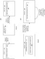
- FIGS. 2A-D are block diagrams illustrating a workflow for ensuring data consistency between devices using configuration signatures, according to one embodiment described herein.
- FIG. 2A shows a system 200 that includes device A 210, configuration application 139 and a device B 220.
- the device A 210 could be a modular device in an industrial automation environment and the device B 220 could be a controller device in the industrial automation environment. More generally, however, it is contemplated that the communication techniques described herein could be applied by a variety of different devices.
- the configuration application 139 has generated and transmits configuration data 215 to device A 210 (operation 225) and has generated and transmits a configuration signature 218 for the configuration data to device B (operation 228).
- the configuration data 215 represents data storing information on configuration settings for the device A 210. These configuration settings could be physical configurations for the device A 210 (e.g., data describing the state of a physical switch), configuration values from a configuration file or database, etc.
- the configuration application 139 has generated the configuration signature 218 using data values from the configuration data 215 for a plurality of predetermined configuration settings.
- the plurality of predetermined configuration settings can be selected based on the configuration settings that impact (directly or indirectly) the contents of messages transmitted between the device A 210 and device B 220. That is, the device B 220 may only be concerned with changes to configuration settings that affect the operation of the device B 220, and thus data values for configuration settings that do not impact device B 220 and messages sent between device A 210 and device B 220 may be omitted from the configuration signature 218.
- the configuration application 139 upon generating the configuration signature 218, the configuration application 139 transmits the configuration signature 218 to the device B 220.
- FIG. 2B depicts a system 230, which illustrates the devices 210 and 220 are at subsequent point in time. More specifically, the system 230 depicts a moment in time when device A 210 has completed initialization (e.g., when the device A 210 has finished booting up after a restart).
- the configuration signature generation component 155 on the device A 210 upon initialization, generates a current configuration signature 233 from the configuration data 215 and transmits this signature to the device B 220 (operation 235).
- a configuration management component 220 on the device B compares the received configuration signature with the previously stored configuration signatures and verifies that these configuration signatures match (operation 240).
- the configuration management component 120 can determine whether the configuration of the device A 210 has changed in a meaningful way (i.e., in a way that affects the operation of device B and/or the communications between device A 210 and device B 220) by comparing the configuration signatures.
- FIG. 2C illustrates a system 250, in which the configuration of device A 210 has been modified (e.g., by an administrator of the device A 210, due to a hardware failure, etc.).
- the configuration signature generation component 155 on the device A 210 generates a new configuration signature 260 based on the updated configuration data 255 (operation 265).
- the device communications component 150 on the device A 210 transmits a message containing the updated configuration signature to the device B (operation 280).
- the device management component 120 on the device B 220 compares the received signature with the previously stored configuration signature and upon determining that the signatures do not match (i.e., because one or more data values for the plurality of predefined configuration settings on device A has changed in the configuration data 255), the device management component 120 generates a notification to alert a user to the configuration mismatch (operation 285). Additionally, the device management component 120 can take one or more remedial actions responsive to the configuration signatures not matching, such as halting operations between the device A 210 and device B 220, flagging data received from the device A 210 after the configuration mismatch as of questionable integrity, and so on.
- FIG. 3 illustrates a workflow for ensuring data consistency between devices at a control device using configuration signatures, according to one embodiment described herein.
- the method 300 begins at block 310, where the configuration management component 120 receives and stores a baseline configuration signature for a first device.
- the baseline configuration signature could be generated upon the initial configuration of the first device.
- the configuration management component 120 receives a current configuration signature from the first device (block 315).
- the configuration management component 120 compares the current configuration signature with the baseline configuration signature (block 320) and if the signatures match (YES, at block 325), the method 300 returns to block 315.
- the configuration management component 120 determines the signatures do not match (NO, at block 325), the configuration management component 120 generates a notification and halts one or more processing operations related to the first device (block 330), and the method 300 ends.
- FIG. 4 illustrates a workflow for ensuring data consistency between devices at a modular device using configuration signatures, according to one embodiment described herein.
- the method 400 begins at block 410, where upon initialization of the first modular device, the configuration signature generation component 155 generates a current configuration signature using current data values for the predefined set of configuration parameters. Generally, if the data values for the predefined set of configuration parameters have not changed, the current configuration signature will be identical to the baseline configuration signature previously stored on the control device (e.g., after the control device receives the baseline configuration signature from the control application). On the other hand, if one or more of the data values has been modified, then the configuration signatures will not match.
- the configuration signature generation component 155 receives a baseline configuration signature from the control device, where the baseline configuration signature was provided to the control device by a configuration application (block 415). For example, upon configuring the first modular device, the configuration application 139 could generate the baseline configuration signature and the configuration application 139 could provide the baseline configuration signature to the control device for storage. In the depicted embodiment, the first modular device compares the received baseline configuration signature with the generated current configuration signature (block 420) and determines whether the signatures match (block 425). If the signatures do match, the method 400 returns to block 410. On the other hand, if the device communications component 150 of the modular device determines the signatures do not match, the device communications component 150 generates a notification and halts one or more processing operations on the first modular device (block 430), and the method 400 ends.
- aspects disclosed herein may be implemented as a system, method or computer program product. Accordingly, aspects may take the form of an entirely hardware embodiment, an entirely software embodiment (including firmware, resident software, micro-code, etc.) or an embodiment combining software and hardware aspects that may all generally be referred to herein as a "circuit,” “module” or “system.” Furthermore, aspects may take the form of a computer program product embodied in one or more computer-readable medium(s) having computer-readable program code embodied thereon.
- the computer-readable medium may be a non-transitory computer-readable medium.
- a non-transitory computer-readable medium may be, for example, but not limited to, an electronic, magnetic, optical, electromagnetic, infrared, or semiconductor system, apparatus, or device, or any suitable combination of the foregoing.
- non-transitory computer-readable medium can include the following: an electrical connection having one or more wires, a portable computer diskette, a hard disk, a random access memory (RAM), a read-only memory (ROM), an erasable programmable read-only memory (EPROM or Flash memory), an optical fiber, a portable compact disc read-only memory (CD-ROM), an optical storage device, a magnetic storage device, or any suitable combination of the foregoing.
- Program code embodied on a computer-readable medium may be transmitted using any appropriate medium, including but not limited to wireless, wireline, optical fiber cable, RF, etc., or any suitable combination of the foregoing.
- Computer program code for carrying out operations for aspects of the present disclosure may be written in any combination of one or more programming languages. Moreover, such computer program code can execute using a single computer system or by multiple computer systems communicating with one another (e.g., using a local area network (LAN), wide area network (WAN), the Internet, etc.). While various features in the preceding are described with reference to flowchart illustrations and/or block diagrams, a person of ordinary skill in the art will understand that each block of the flowchart illustrations and/or block diagrams, as well as combinations of blocks in the flowchart illustrations and/or block diagrams, can be implemented by computer logic (e.g., computer program instructions, hardware logic, a combination of the two, etc.).
- computer logic e.g., computer program instructions, hardware logic, a combination of the two, etc.
- computer program instructions may be provided to a processor(s) of a general-purpose computer, special-purpose computer, or other programmable data processing apparatus. Moreover, the execution of such computer program instructions using the processor(s) produces a machine that can carry out a function(s) or act(s) specified in the flowchart and/or block diagram block or blocks.
- each block in the flowchart or block diagrams may represent a module, segment or portion of code, which comprises one or more executable instructions for implementing the specified logical function(s).
- the functions noted in the block may occur out of the order noted in the figures. For example, two blocks shown in succession may, in fact, be executed substantially concurrently, or the blocks may sometimes be executed in the reverse order, depending upon the functionality involved.
Landscapes
- Engineering & Computer Science (AREA)
- Computer Security & Cryptography (AREA)
- Theoretical Computer Science (AREA)
- Signal Processing (AREA)
- Computer Networks & Wireless Communication (AREA)
- Software Systems (AREA)
- General Physics & Mathematics (AREA)
- General Engineering & Computer Science (AREA)
- Physics & Mathematics (AREA)
- Computer Hardware Design (AREA)
- Power Engineering (AREA)
- Data Mining & Analysis (AREA)
- Databases & Information Systems (AREA)
- Automation & Control Theory (AREA)
- Programmable Controllers (AREA)
Abstract
Description
- The present disclosure relates to device communications, and more specifically to communication techniques for detecting and accounting for configuration changes in a modular device to ensure data consistency between the modular device and an external system.
- Industry today utilizes the electric motor to perform a wide array of tasks. Generally, various types of motors may be used depending on the particular application. Electric motors may be utilized for fixed speed, variable speed, and/or positional control of various types of industrial equipment. In most industrial applications a motor controller is utilized along with the motor itself to form a motor control system. Motor controllers may include logic and hardware for starting and stopping a motor, selecting the motor rotation, selecting and regulating the speed, regulating or limiting the torque, and/or various protection functions such as overloads and/or faults. Frequently, a number of other devices may be used alongside such electric motors in industrial applications (e.g., sensor devices, application-specific devices, and so on), adding complexity to the device communications for the system. Additionally, such devices may be modular devices, which are capable of various configurations and may operate in a different manner depending on their configuration. While a modular device can offer additional flexibility and functionality, other devices in the industrial system may need to be configured to account for the current configuration of the modular device. When the configuration of the modular device changes, these other devices may need to be reconfigured to reflect the new configuration of the modular device, as otherwise the system may not perform as intended and may result in erroneous behavior and/or system downtime. These difficulties are exacerbated in environments where, due to business reasons, downtime and other interruptions needs to be minimized.
- A more detailed description of the disclosure, briefly summarized above, may be had by reference to various embodiments, some of which are illustrated in the appended drawings. While the appended drawings illustrate select embodiments of this disclosure, these drawings are not to be considered limiting of its scope, for the disclosure may admit to other equally effective embodiments.
-
FIG. 1 is a block diagram illustrating a system configured with a configuration management component, according to one embodiment described herein. -
FIGS. 2A-D are block diagrams illustrating a workflow for ensuring data consistency between devices using configuration signatures, according to one embodiment described herein. -
FIG. 3 illustrates a workflow for ensuring data consistency between devices at a control device using configuration signatures, according to one embodiment described herein. -
FIG. 4 illustrates a workflow for ensuring data consistency between devices at a modular device using configuration signatures, according to one embodiment described herein. - Identical reference numerals have been used, where possible, to designate identical elements that are common to the figures. However, elements disclosed in one embodiment may be beneficially utilized on other embodiments without specific recitation.
- One embodiment described herein provides a method for ensuring data consistency between devices at a control device using configuration signatures. The method includes receiving and storing a baseline configuration signature for a first modular device. The method also includes receiving, upon initialization of the first modular device, a current configuration signature from the first modular device. The method further includes comparing the current configuration signature with the baseline configuration signature and, if a mismatch is found, generating a notification and halting one or more processing operations related to the first modular device.
- Another embodiment described herein provides a method for ensuring data consistency between devices at a modular device using configuration signatures. The method includes upon initialization of the first modular device, generating a current configuration signature using current data values for the predefined set of configuration parameters. The method also includes receiving a baseline configuration signature from a control device, wherein the baseline configuration signature was provided to the control device by a configuration application when the first modular device was configured. Additionally, the method includes comparing the received baseline configuration signature with the generated current configuration signature. The method further includes, upon determining the current configuration signature and the received baseline configuration signature do not match, generating a notification and halting one or more processing operations for the first modular device.
-
FIG. 1 is a block diagram illustrating a system configured with a configuration management component, according to one embodiment described herein. As shown, thesystem 100 includes a Programmable Logic Controller (PLC) 110, a configuration system 137 and amodular device 140, interconnected via anetwork 135. Generally, thenetwork 135 represents any suitable data communications network, with examples including (without limitation) a local area network (LAN), a wide area network (WAN), an IEEE 802.11 wireless network, and so on. - The PLC 110 includes one or
more computer processors 112, amemory 115, an input module(s) 122, an output module(s) 125, and anetwork interface controller 127. Generally, the input module(s) 122 represent devices that provide inputs to thePLC 110. Such inputs may be provided, for example, in the form of digital inputs or analog signals. In the case of analog signals, the input module(s) 122 can include circuitry for converting the analog signals into logic signals that can be processed by theprocessor 112. The output module(s) 125 generally convert logic signals from theprocessor 112 into digital or analog values for use in controlling output devices. Thememory 115 contains application-specific program logic 118 and a deviceconfiguration server component 120. Generally, the application-specific program logic 118 represents software logic that performs various application-specific operations, depending on the type of thecomputing environment 100. For example, aPLC device 110 within an industrial automation environment may perform different application-specific operations than aPLC device 110 within a fulfillment center environment. - The
modular device 140 includes acomputer processor 142, amemory 145, an input module(s) 156, an output module(s) 158, and anetwork interface controller 159. Generally, the input module(s) 156 represent devices that provide inputs to themodular device 140. Such inputs may be provided in the form of digital inputs or analog signals, for example. For the latter, the input module(s) 156 can include circuitry for converting the analog signals into logic signals that can be processed by theprocessor 142. The output module(s) 158 generally convert logic signals from theprocessor 142 into digital or analog values for outputting to output devices. Thenetwork interface controller 159, like thenetwork interface controller 127, facilitates communication with thenetwork 135. - One or more end node devices 160(1)-(N) may also be present in the
system 100. Each end node device 160(1)-(N) includes, respectively, a computer processor 162(1)-(N), a memory 165(1)-(N), and an input module(s) 180(1)-(N). The input module(s) 180(1)-(N) represent devices that provide inputs to their respective end node devices 160(1)-(N) in a manner similar to their counterpart input modules in thePLC 110 andmodular device 140. - Any general-purpose computer systems used in various embodiments of this disclosure may be, for example, general-purpose computers with general-purpose computer processors. For example, the
processors processors - The
memories memories - One or more portions of the computer system may be distributed across one or more computer systems coupled to a communications network. For example, as discussed above, a computer system that determines available power capacity may be located remotely from a system manager. These computer systems also may be general-purpose computer systems. For example, various aspects of the disclosure may be distributed among one or more computer systems configured to provide a service (e.g., servers) to one or more client computers, or to perform an overall task as part of a distributed system. For example, various aspects of the disclosure may be performed on a client-server or multi-tier system that includes components distributed among one or more server systems that perform various functions according to various embodiments of the disclosure. These components may be executable, intermediate (e.g., IL) or interpreted (e.g., Java) code which communicate over a communication network (e.g., the Internet) using a communication protocol (e.g., TCP/IP). For example, one or more database servers may be used to store device data, such as expected power draw, that is used in designing layouts associated with embodiments of the present disclosure.
- As shown, the
memory 115 contains application-specific program logic 118 and aconfiguration management component 120. Thememory 145 contains adevice communications component 150, which in turn contains a configurationsignature generation component 155. Furthermore, the memories 165(1)-(N) each contain a respective device communications component 170(1)-(N), which in turn contain configuration signature generation components 175(1)-(N). ThePLC 110 is communicatively coupled to adata store 130, which in the depicted embodiment contains configuration data 133. - In the depicted example, the configuration system 137 includes a
configuration application 139. Generally, theconfiguration application 139 can be used to configure themodular device 140 and/or end node devices 160(1)-(N). For example, theconfiguration application 139 could provide a human-machine interface (HMI) through which an administrator can generate a configuration profile for one or more of thedevices 140 and 160(1)-(N). Theconfiguration application 139 could then deploy the generated configuration profile onto the one or more devices. When doing so, the configuration application could identify a plurality of predetermined configuration parameters and can generate a configuration signature from data values in the initial configuration for the plurality of predetermined configuration parameters. In one embodiment, theconfiguration application 139 is configured to use a hash function on the data values for the plurality of predetermined configuration parameters to generate the configuration signature (e.g., a 256-bit hash value). - Generally, the plurality of predetermined configuration parameters includes configuration parameters that can impact the operation of the modular device when interacting with the
PLC 110. For example, a first parameter could be included in the plurality of configuration parameters if its data value can impact an operation performed between thePLC 110 and themodular device 140, while a second parameter could be excluded if it would affect the performance of themodular device 140 but would not impact the operation performed between thePLC 110 and themodular device 140. - In a particular embodiment, the plurality of predetermined configuration parameters define a communication protocol for implicit communications between the
PLC 110 and themodular device 140. For example, themodular device 140 may be configured to periodically transmit a plurality of data values, of various data types, of various sizes, and in a particular order to thePLC 110, and such a configuration can be defined in configuration data stored on themodular device 140. Likewise, thePLC 110 may be configured with configuration data that defines the attributes of incoming data message and, based on this configuration data, thePLC 110 may expect transmissions from themodular device 140 to contain data for the ordered sequence of data types and may expect each data type to have the specified size, and so on. - One advantage to such implicit communications protocols is that there is less overhead to the communications between the
PLC 110 and themodular device 140 relative to alternative communication protocols. For example, by agreeing on the ordering of data values of defined types and sizes ahead of time and defining this in the configuration data, themodular device 140 is able to transmit data values to the PLC 110 (or vice versa) without any embedded tags (e.g., that define the type of the data values and delimit the individual data values). While such a communications protocol offers many advantages, the protocol may break down if either themodular device 140 and/or thePLC 110 unilaterally make changes to their configuration data without coordinating with each other. That is, if themodular device 140 changes the size of the first data value themodular device 140 is sending to thePLC 110 from 8 bytes to 16 bytes, but thePLC 110 still expects the first data value to be an 8-byte value, thePLC 110 may misinterpret the message received from the modular device. As such, embodiments described herein can generate configuration signatures by hashing the configuration data that defines the implicit communications protocol between thePLC 110 andmodular device 140 and can compare these configuration signatures over time to ensure the communications protocol is still being followed by both devices. - The
configuration management component 120 can receive the generated configuration signature from the configuration application 139 (e.g., using the network 135) and could store the signature in the configuration data 133 of thedata store 130. Upon subsequent initialization of the modular device 140 (e.g., after the device is restarted), thedevice communications component 150 of themodular device 140 could provide an updated configuration signature to theconfiguration management component 120 of thePLC 110. For example, the configurationsignature generation component 155 could retrieve current data values for the plurality of predetermined configuration parameters and could generate the configuration signature (e.g., a 256-bit hash value) using the current data values. - Upon receiving the updated configuration signature, the
configuration management component 120 could compare the updated configuration signature with the previously stored configuration signature in thedata store 130. If the signatures match, theconfiguration management component 120 could determine that the data coming from themodular device 140 has integrity and take no further action at this time. On the other hand, if theconfiguration management component 120 determines that the signatures do not match, theconfiguration management component 120 could generate a notification (e.g., to alert a user of the issue) and could halt one or more data processing operations relating to themodular device 140. In one embodiment, theconfiguration management component 120 can any flag data received from themodular device 140 subsequent to the signature mismatch to indicate the data is of uncertain integrity. - Of note, although in the aforementioned example the comparison is performed by the
configuration management component 120, in an alternate embodiment theconfiguration management component 120 could transmit the previously stored signature to themodular device 140 upon initialization of themodular device 140, and thedevice communications component 150 can compare the signatures to determine whether a mismatch exists. Moreover, while the aforementioned example involves thedevice communications component 150 and configurationsignature generation component 155, it is contemplated that the same functionality can be performed by the device communications components 170(1)-(N) and configuration signature generation components 175(1)-(N). For example, the configuration signature generation component 175(1), upon initial configuration of the end node device 160(1), could generate a baseline configuration signature and could transmit this baseline configuration signature to thePLC 110 for storage in thedata store 130. ThePLC 110 can then perform comparison operations between the baseline configuration signature and subsequently generated configuration signatures received from the end node device 160(1) to determine whether the configuration of the end node device 160(1) has changed (and, e.g., if so, could generate a notification and halt one or more processing operations with the end node device 160(1)). -
FIGS. 2A-D are block diagrams illustrating a workflow for ensuring data consistency between devices using configuration signatures, according to one embodiment described herein. As shown,FIG. 2A shows asystem 200 that includesdevice A 210,configuration application 139 and adevice B 220. For example, thedevice A 210 could be a modular device in an industrial automation environment and thedevice B 220 could be a controller device in the industrial automation environment. More generally, however, it is contemplated that the communication techniques described herein could be applied by a variety of different devices. - In the depicted embodiment, the
configuration application 139 has generated and transmits configuration data 215 to device A 210 (operation 225) and has generated and transmits aconfiguration signature 218 for the configuration data to device B (operation 228). Generally, the configuration data 215 represents data storing information on configuration settings for thedevice A 210. These configuration settings could be physical configurations for the device A 210 (e.g., data describing the state of a physical switch), configuration values from a configuration file or database, etc. In the depicted embodiment, theconfiguration application 139 has generated theconfiguration signature 218 using data values from the configuration data 215 for a plurality of predetermined configuration settings. The plurality of predetermined configuration settings can be selected based on the configuration settings that impact (directly or indirectly) the contents of messages transmitted between thedevice A 210 anddevice B 220. That is, thedevice B 220 may only be concerned with changes to configuration settings that affect the operation of thedevice B 220, and thus data values for configuration settings that do not impactdevice B 220 and messages sent betweendevice A 210 anddevice B 220 may be omitted from theconfiguration signature 218. In the depicted embodiment, upon generating theconfiguration signature 218, theconfiguration application 139 transmits theconfiguration signature 218 to thedevice B 220. -
FIG. 2B depicts asystem 230, which illustrates thedevices system 230 depicts a moment in time whendevice A 210 has completed initialization (e.g., when thedevice A 210 has finished booting up after a restart). In the depicted embodiment, the configurationsignature generation component 155 on thedevice A 210, upon initialization, generates acurrent configuration signature 233 from the configuration data 215 and transmits this signature to the device B 220 (operation 235). Upon receiving the configuration signature, aconfiguration management component 220 on the device B compares the received configuration signature with the previously stored configuration signatures and verifies that these configuration signatures match (operation 240). That is, because the configuration signatures are generated using data values for configuration settings that can impact thedevice B 220 and/or the communications betweendevice A 210 anddevice B 220, theconfiguration management component 120 can determine whether the configuration of thedevice A 210 has changed in a meaningful way (i.e., in a way that affects the operation of device B and/or the communications betweendevice A 210 and device B 220) by comparing the configuration signatures. -
FIG. 2C illustrates asystem 250, in which the configuration ofdevice A 210 has been modified (e.g., by an administrator of thedevice A 210, due to a hardware failure, etc.). In the depicted example, the configurationsignature generation component 155 on thedevice A 210 generates anew configuration signature 260 based on the updated configuration data 255 (operation 265). In thesystem 270 shown inFIG. 2D , thedevice communications component 150 on thedevice A 210 transmits a message containing the updated configuration signature to the device B (operation 280). Thedevice management component 120 on thedevice B 220 compares the received signature with the previously stored configuration signature and upon determining that the signatures do not match (i.e., because one or more data values for the plurality of predefined configuration settings on device A has changed in the configuration data 255), thedevice management component 120 generates a notification to alert a user to the configuration mismatch (operation 285). Additionally, thedevice management component 120 can take one or more remedial actions responsive to the configuration signatures not matching, such as halting operations between thedevice A 210 anddevice B 220, flagging data received from thedevice A 210 after the configuration mismatch as of questionable integrity, and so on. -
FIG. 3 illustrates a workflow for ensuring data consistency between devices at a control device using configuration signatures, according to one embodiment described herein. As shown, themethod 300 begins atblock 310, where theconfiguration management component 120 receives and stores a baseline configuration signature for a first device. For example, the baseline configuration signature could be generated upon the initial configuration of the first device. At a subsequent point in time, upon initialization of the first device (e.g., after a restart operation), theconfiguration management component 120 receives a current configuration signature from the first device (block 315). Theconfiguration management component 120 compares the current configuration signature with the baseline configuration signature (block 320) and if the signatures match (YES, at block 325), themethod 300 returns to block 315. On the other hand, if theconfiguration management component 120 determines the signatures do not match (NO, at block 325), theconfiguration management component 120 generates a notification and halts one or more processing operations related to the first device (block 330), and themethod 300 ends. -
FIG. 4 illustrates a workflow for ensuring data consistency between devices at a modular device using configuration signatures, according to one embodiment described herein. As shown, themethod 400 begins at block 410, where upon initialization of the first modular device, the configurationsignature generation component 155 generates a current configuration signature using current data values for the predefined set of configuration parameters. Generally, if the data values for the predefined set of configuration parameters have not changed, the current configuration signature will be identical to the baseline configuration signature previously stored on the control device (e.g., after the control device receives the baseline configuration signature from the control application). On the other hand, if one or more of the data values has been modified, then the configuration signatures will not match. - The configuration
signature generation component 155 receives a baseline configuration signature from the control device, where the baseline configuration signature was provided to the control device by a configuration application (block 415). For example, upon configuring the first modular device, theconfiguration application 139 could generate the baseline configuration signature and theconfiguration application 139 could provide the baseline configuration signature to the control device for storage. In the depicted embodiment, the first modular device compares the received baseline configuration signature with the generated current configuration signature (block 420) and determines whether the signatures match (block 425). If the signatures do match, themethod 400 returns to block 410. On the other hand, if thedevice communications component 150 of the modular device determines the signatures do not match, thedevice communications component 150 generates a notification and halts one or more processing operations on the first modular device (block 430), and themethod 400 ends. - In the preceding, reference is made to various embodiments. However, the scope of the present disclosure is not limited to the specific described embodiments. Instead, any combination of the described features and elements, whether related to different embodiments or not, is contemplated to implement and practice contemplated embodiments. Furthermore, although embodiments may achieve advantages over other possible solutions or over the prior art, whether or not a particular advantage is achieved by a given embodiment is not limiting of the scope of the present disclosure. Thus, the preceding aspects, features, embodiments and advantages are merely illustrative and are not considered elements or limitations of the appended claims except where explicitly recited in a claim(s).
- The various embodiments disclosed herein may be implemented as a system, method or computer program product. Accordingly, aspects may take the form of an entirely hardware embodiment, an entirely software embodiment (including firmware, resident software, micro-code, etc.) or an embodiment combining software and hardware aspects that may all generally be referred to herein as a "circuit," "module" or "system." Furthermore, aspects may take the form of a computer program product embodied in one or more computer-readable medium(s) having computer-readable program code embodied thereon.
- Any combination of one or more computer-readable medium(s) may be utilized. The computer-readable medium may be a non-transitory computer-readable medium. A non-transitory computer-readable medium may be, for example, but not limited to, an electronic, magnetic, optical, electromagnetic, infrared, or semiconductor system, apparatus, or device, or any suitable combination of the foregoing. More specific examples (a non-exhaustive list) of the non-transitory computer-readable medium can include the following: an electrical connection having one or more wires, a portable computer diskette, a hard disk, a random access memory (RAM), a read-only memory (ROM), an erasable programmable read-only memory (EPROM or Flash memory), an optical fiber, a portable compact disc read-only memory (CD-ROM), an optical storage device, a magnetic storage device, or any suitable combination of the foregoing. Program code embodied on a computer-readable medium may be transmitted using any appropriate medium, including but not limited to wireless, wireline, optical fiber cable, RF, etc., or any suitable combination of the foregoing.
- Computer program code for carrying out operations for aspects of the present disclosure may be written in any combination of one or more programming languages. Moreover, such computer program code can execute using a single computer system or by multiple computer systems communicating with one another (e.g., using a local area network (LAN), wide area network (WAN), the Internet, etc.). While various features in the preceding are described with reference to flowchart illustrations and/or block diagrams, a person of ordinary skill in the art will understand that each block of the flowchart illustrations and/or block diagrams, as well as combinations of blocks in the flowchart illustrations and/or block diagrams, can be implemented by computer logic (e.g., computer program instructions, hardware logic, a combination of the two, etc.). Generally, computer program instructions may be provided to a processor(s) of a general-purpose computer, special-purpose computer, or other programmable data processing apparatus. Moreover, the execution of such computer program instructions using the processor(s) produces a machine that can carry out a function(s) or act(s) specified in the flowchart and/or block diagram block or blocks.
- The flowchart and block diagrams in the Figures illustrate the architecture, functionality and/or operation of possible implementations of various embodiments of the present disclosure. In this regard, each block in the flowchart or block diagrams may represent a module, segment or portion of code, which comprises one or more executable instructions for implementing the specified logical function(s). It should also be noted that, in some alternative implementations, the functions noted in the block may occur out of the order noted in the figures. For example, two blocks shown in succession may, in fact, be executed substantially concurrently, or the blocks may sometimes be executed in the reverse order, depending upon the functionality involved. It will also be noted that each block of the block diagrams and/or flowchart illustration, and combinations of blocks in the block diagrams and/or flowchart illustration, can be implemented by special purpose hardware-based systems that perform the specified functions or acts, or combinations of special purpose hardware and computer instructions.
- It is to be understood that the above description is intended to be illustrative, and not restrictive. Many other implementation examples are apparent upon reading and understanding the above description. Although the disclosure describes specific examples, it is recognized that the systems and methods of the disclosure are not limited to the examples described herein but may be practiced with modifications within the scope of the appended claims. Accordingly, the specification and drawings are to be regarded in an illustrative sense rather than a restrictive sense.
- The scope of the disclosure should, therefore, be determined with reference to the appended claims, along with the full scope of equivalents to which such claims are entitled.
Claims (15)
- A method, comprising:receiving, from a configuration application, by a computing device, and storing a baseline configuration signature for a first modular device;upon initialization of the first modular device, receiving, over a first data communications network, a current configuration signature from the first modular device;comparing the current configuration signature with the baseline configuration signature; andupon determining the current configuration signature and the baseline configuration signature do not match, generating, by operation of one or more computer processors, a notification indicating that data subsequently received from the first modular device is of uncertain integrity.
- The method of claim 1, wherein the baseline configuration signature is generated by the configuration application and received from the configuration application over a second data communications network.
- The method of claim 2, wherein the configuration application is configured to generate the baseline configuration signature using initial configuration data for the first modular device and upon successful configuration of the first modular device.
- The method of claim 3, wherein the first modular device is configured, upon initialization, to retrieve configuration data on the first modular device at the time of initialization and to generate the current configuration signature using the retrieved configuration data.
- The method of claim 4, wherein the baseline configuration signature comprises a hash value, and wherein the configuration application is configured to use the initial configuration data as input to a predefined hash function to generate the baseline configuration signature.
- The method of claim 5, wherein the current configuration signature comprises a second hash value, and wherein the first modular device, upon initialization, is configured to use the retrieved configuration data as input to the predefined hash function to generate the current configuration signature.
- The method of claim 1, further comprising:
subsequent to determining the current configuration signature and the baseline configuration signature do not match, flagging one or more data values received from the first modular device as of uncertain integrity. - The method of claim 4, wherein the initial configuration data and the retrieved configuration data each define a communication protocol for an implicit communication of data between the first modular device and the computing device.
- The method of claim 8, wherein the defined communication protocols specify at least one of a plurality of data types to be transmitted, an ordering of the plurality of data types, and a size of at least one of the plurality of data types.
- A method, comprising:upon initialization of a first modular device, generating a current configuration signature using current data values for a predefined set of configuration parameters;receive a baseline configuration signature from a control device, wherein the baseline configuration signature was provided to the control device by a configuration application when the first modular device was configured;comparing the received baseline configuration signature with the generated current configuration signature; andupon determining the current configuration signature and the received baseline configuration signature do not match, generating a notification indicating that data communicated between the first modular device and the control device are of uncertain integrity.
- The method of claim 10, wherein the baseline configuration signature is generated by a configuration application; wherein the configuration application is configured to generate the baseline configuration signature using initial configuration data for the first modular device and upon successful configuration of the first modular device; and wherein the baseline configuration signature comprises a hash value, and wherein the configuration application is configured to use the initial configuration data as input to a predefined hash function to generate the baseline configuration signature.
- The method of claim 11, wherein the current configuration signature comprises a second hash value, and wherein the first modular device, upon initialization, is configured to use the current data values for the predefined set of configuration parameters input to the predefined hash function to generate the current configuration signature; wherein the initial configuration data and the retrieved configuration data each define a communication protocol for an implicit communication of data between the first modular device and the computing device; and wherein the defined communication protocols specify at least one of a plurality of data types to be transmitted, an ordering of the plurality of data types, and a size of at least one of the plurality of data types.
- A system, comprising:a modular device, comprising:a first one or more computer processors; anda first non-transitory memory containing computer program code that, when executed by operation of the first one or more computer processors, performs a first operation; anda control device, comprising:a second one or more computer processors; anda second non-transitory memory containing computer program code that, when executed by operation of the second one or more computer processors, performs a second operation;wherein the first operation comprises:upon initialization, generating a current configuration signature using current data values for a predefined set of configuration parameters, wherein the predefined set of configuration parameters define an implicit communications protocol for communications between the modular device and the control device; andtransmitting the current configuration signature to the control device over a data communications network; andwherein the second operation comprises:receiving, from a configuration application, and storing a baseline configuration signature for the modular device;receiving, from the modular device, the current configuration signature;comparing the current configuration signature with the baseline configuration signature; andupon determining the current configuration signature and the baseline configuration signature do not match, generating a notification indicating that data subsequently received from the modular device is of uncertain integrity.
- The system of claim 13, wherein the baseline configuration signature is generated by the configuration application using initial configuration data that defines an implicit communications protocol for an implicit communication of data between the modular device and the control device.
- The system of claim 14, wherein the defined communication protocols specify at least one of a plurality of data types to be transmitted, an ordering of the plurality of data types, and a size of at least one of the plurality of data types.
Applications Claiming Priority (1)
| Application Number | Priority Date | Filing Date | Title |
|---|---|---|---|
| US201962869938P | 2019-07-02 | 2019-07-02 |
Publications (2)
| Publication Number | Publication Date |
|---|---|
| EP3761125A1 true EP3761125A1 (en) | 2021-01-06 |
| EP3761125B1 EP3761125B1 (en) | 2024-05-15 |
Family
ID=71465074
Family Applications (1)
| Application Number | Title | Priority Date | Filing Date |
|---|---|---|---|
| EP20183736.6A Active EP3761125B1 (en) | 2019-07-02 | 2020-07-02 | Ensuring data consistency between a modular device and a control device |
Country Status (3)
| Country | Link |
|---|---|
| US (2) | US11405217B2 (en) |
| EP (1) | EP3761125B1 (en) |
| CN (1) | CN112181509B (en) |
Families Citing this family (3)
| Publication number | Priority date | Publication date | Assignee | Title |
|---|---|---|---|---|
| US12003365B1 (en) * | 2019-09-24 | 2024-06-04 | Amazon Technologies, Inc. | Configuration change tracking |
| EP4372589A1 (en) * | 2022-11-16 | 2024-05-22 | Siemens Aktiengesellschaft | Monitoring system for subsequent inspection of system integrity |
| US20250233751A1 (en) * | 2024-01-11 | 2025-07-17 | Schneider Electric USA, Inc. | Temporary Enablement of Functionality of a Secure Device |
Citations (1)
| Publication number | Priority date | Publication date | Assignee | Title |
|---|---|---|---|---|
| US20160179556A1 (en) * | 2014-12-17 | 2016-06-23 | Intel Corporation | Input/output (i/o) device configuration signature |
Family Cites Families (19)
| Publication number | Priority date | Publication date | Assignee | Title |
|---|---|---|---|---|
| WO2002023364A1 (en) * | 2000-09-15 | 2002-03-21 | Wonderware Corporation | An industrial process control data access server supporting multiple client data exchange protocols |
| US8402536B2 (en) * | 2008-04-15 | 2013-03-19 | Nokia Corporation | Signature based authentication of the configuration of a configurable logic component |
| US8276202B1 (en) * | 2009-06-30 | 2012-09-25 | Aleksandr Dubrovsky | Cloud-based gateway security scanning |
| AU2012300852C1 (en) * | 2011-08-31 | 2018-01-04 | Thomson Licensing | Method for a secured backup and restore of configuration data of an end-user device, and device using the method |
| EP2757498A1 (en) * | 2013-01-16 | 2014-07-23 | ABB Research Ltd. | Security agent for an endpoint device of a control system |
| US20140280846A1 (en) * | 2013-03-14 | 2014-09-18 | Douglas Gourlay | System and method for abstracting network policy from physical interfaces and creating portable network policy |
| US9578117B2 (en) * | 2013-09-20 | 2017-02-21 | Amazon Technologies, Inc. | Service discovery using a network |
| CN106462694A (en) * | 2014-05-29 | 2017-02-22 | 三菱电机株式会社 | Device control system, device controller, device control method, and program |
| US11442919B2 (en) * | 2015-07-31 | 2022-09-13 | Accenture Global Services Limited | Data reliability analysis |
| US10514683B2 (en) * | 2015-09-16 | 2019-12-24 | Profire Energy, Inc. | Distributed networking system and method to implement a safety state environment |
| KR101977109B1 (en) * | 2015-11-17 | 2019-08-28 | (주)마크애니 | Large simultaneous digital signature service system based on hash function and method thereof |
| US10447540B2 (en) * | 2016-04-08 | 2019-10-15 | Cisco Technology, Inc. | Deriving a network policy for an industrial automation network |
| US10545770B2 (en) * | 2016-11-14 | 2020-01-28 | Intel Corporation | Configurable client hardware |
| US10360402B2 (en) * | 2016-11-15 | 2019-07-23 | International Business Machines Corporation | Intercepting sensitive data using hashed candidates |
| US10404833B1 (en) * | 2017-03-22 | 2019-09-03 | Intuit, Inc. | Cloud-based dynamic software configuration for global mobile applications |
| JP6625269B2 (en) * | 2017-05-09 | 2019-12-25 | 三菱電機株式会社 | In-vehicle authentication system, vehicle communication device, authentication management device, in-vehicle authentication method, and in-vehicle authentication program |
| JP7398438B2 (en) * | 2018-05-11 | 2023-12-14 | ラティス セミコンダクタ コーポレーション | Key provisioning system and method for programmable logic devices |
| US10896266B1 (en) * | 2018-07-12 | 2021-01-19 | Amazon Technologies, Inc. | Computer hardware attestation |
| US10838386B1 (en) * | 2019-09-26 | 2020-11-17 | Rockwell Automation Technologies, Inc. | Distributed modular I/O device with configurable single-channel I/O submodules |
-
2020
- 2020-07-02 US US16/919,502 patent/US11405217B2/en active Active
- 2020-07-02 EP EP20183736.6A patent/EP3761125B1/en active Active
- 2020-07-02 CN CN202010634147.1A patent/CN112181509B/en active Active
-
2022
- 2022-06-29 US US17/852,361 patent/US11843704B2/en active Active
Patent Citations (1)
| Publication number | Priority date | Publication date | Assignee | Title |
|---|---|---|---|---|
| US20160179556A1 (en) * | 2014-12-17 | 2016-06-23 | Intel Corporation | Input/output (i/o) device configuration signature |
Also Published As
| Publication number | Publication date |
|---|---|
| EP3761125B1 (en) | 2024-05-15 |
| US11843704B2 (en) | 2023-12-12 |
| US20220329440A1 (en) | 2022-10-13 |
| CN112181509B (en) | 2025-02-07 |
| CN112181509A (en) | 2021-01-05 |
| US11405217B2 (en) | 2022-08-02 |
| US20210006409A1 (en) | 2021-01-07 |
Similar Documents
| Publication | Publication Date | Title |
|---|---|---|
| US11843704B2 (en) | Ensuring data consistency between a modular device and an external system | |
| US11385908B1 (en) | Cloning of firmware configuration settings using rest over IPMI interface | |
| US10409584B1 (en) | Peripheral device firmware update using rest over IPMI interface firmware update module | |
| US10853052B1 (en) | Peripheral device firmware update using rest over IPMI interface firmware shell utility | |
| US9003007B2 (en) | Administration of virtual machine affinity in a data center | |
| CN110392084B (en) | Method, apparatus and computer program product for managing addresses in a distributed system | |
| US10776286B1 (en) | Rest over IPMI interface for firmware to BMC communication | |
| US10996940B1 (en) | Secure firmware integrity monitoring using rest over IPMI interface | |
| US10572242B1 (en) | Firmware update using rest over IPMI interface | |
| US10628176B1 (en) | Firmware configuration using REST over IPMI interface | |
| EP3267649B1 (en) | Method and industrial computing apparatus for performing a secure communication | |
| CN113839964B (en) | Communication method and gateway device for gateway device | |
| CN112346926A (en) | Resource state monitoring method and device and electronic equipment | |
| CN119127261B (en) | Inverter firmware remote upgrade method | |
| KR102210289B1 (en) | Hardware management communication protocol | |
| CN106020135A (en) | Process control system | |
| US9723091B1 (en) | Variable length protocol using serialized payload with compression support | |
| EP2942711B1 (en) | Dynamic generation of proxy connections | |
| US8321495B2 (en) | Byzantine fault-tolerance in distributed computing networks | |
| CN108595195B (en) | Application program updating method, device, terminal and storage medium | |
| CN114217924A (en) | Computing power network arrangement management method and system | |
| JP2022065129A (en) | Message processing method and device, electronic apparatus, storage medium, and program product | |
| EP4246939A1 (en) | System and method for managing client-server communication | |
| CN118363762A (en) | Reasoning task processing method, device, electronic device and storage medium | |
| CN117793038A (en) | Message processing method, device, electronic equipment, computer-readable storage medium |
Legal Events
| Date | Code | Title | Description |
|---|---|---|---|
| PUAI | Public reference made under article 153(3) epc to a published international application that has entered the european phase |
Free format text: ORIGINAL CODE: 0009012 |
|
| STAA | Information on the status of an ep patent application or granted ep patent |
Free format text: STATUS: THE APPLICATION HAS BEEN PUBLISHED |
|
| AK | Designated contracting states |
Kind code of ref document: A1 Designated state(s): AL AT BE BG CH CY CZ DE DK EE ES FI FR GB GR HR HU IE IS IT LI LT LU LV MC MK MT NL NO PL PT RO RS SE SI SK SM TR |
|
| AX | Request for extension of the european patent |
Extension state: BA ME |
|
| STAA | Information on the status of an ep patent application or granted ep patent |
Free format text: STATUS: REQUEST FOR EXAMINATION WAS MADE |
|
| 17P | Request for examination filed |
Effective date: 20210705 |
|
| RBV | Designated contracting states (corrected) |
Designated state(s): AL AT BE BG CH CY CZ DE DK EE ES FI FR GB GR HR HU IE IS IT LI LT LU LV MC MK MT NL NO PL PT RO RS SE SI SK SM TR |
|
| STAA | Information on the status of an ep patent application or granted ep patent |
Free format text: STATUS: EXAMINATION IS IN PROGRESS |
|
| 17Q | First examination report despatched |
Effective date: 20220503 |
|
| GRAP | Despatch of communication of intention to grant a patent |
Free format text: ORIGINAL CODE: EPIDOSNIGR1 |
|
| STAA | Information on the status of an ep patent application or granted ep patent |
Free format text: STATUS: GRANT OF PATENT IS INTENDED |
|
| RIC1 | Information provided on ipc code assigned before grant |
Ipc: G06F 21/57 20130101ALI20231114BHEP Ipc: G05B 19/042 20060101AFI20231114BHEP |
|
| INTG | Intention to grant announced |
Effective date: 20231205 |
|
| GRAS | Grant fee paid |
Free format text: ORIGINAL CODE: EPIDOSNIGR3 |
|
| GRAA | (expected) grant |
Free format text: ORIGINAL CODE: 0009210 |
|
| STAA | Information on the status of an ep patent application or granted ep patent |
Free format text: STATUS: THE PATENT HAS BEEN GRANTED |
|
| AK | Designated contracting states |
Kind code of ref document: B1 Designated state(s): AL AT BE BG CH CY CZ DE DK EE ES FI FR GB GR HR HU IE IS IT LI LT LU LV MC MK MT NL NO PL PT RO RS SE SI SK SM TR |
|
| REG | Reference to a national code |
Ref country code: CH Ref legal event code: EP |
|
| REG | Reference to a national code |
Ref country code: IE Ref legal event code: FG4D |
|
| REG | Reference to a national code |
Ref country code: DE Ref legal event code: R096 Ref document number: 602020030839 Country of ref document: DE |
|
| REG | Reference to a national code |
Ref country code: CH Ref legal event code: PK Free format text: BERICHTIGUNGEN |
|
| RIN2 | Information on inventor provided after grant (corrected) |
Inventor name: FIEN, WOLFGANG Inventor name: RINGWALD, CHRISTIAN Inventor name: FIESS, JUERGEN Inventor name: GOVINDARAJU, SURYA NARAYANA H Inventor name: MARTIN, DANIEL Inventor name: JEFFERIES, KEVIN M. |
|
| REG | Reference to a national code |
Ref country code: LT Ref legal event code: MG9D |
|
| REG | Reference to a national code |
Ref country code: NL Ref legal event code: MP Effective date: 20240515 |
|
| PG25 | Lapsed in a contracting state [announced via postgrant information from national office to epo] |
Ref country code: IS Free format text: LAPSE BECAUSE OF FAILURE TO SUBMIT A TRANSLATION OF THE DESCRIPTION OR TO PAY THE FEE WITHIN THE PRESCRIBED TIME-LIMIT Effective date: 20240915 |
|
| PG25 | Lapsed in a contracting state [announced via postgrant information from national office to epo] |
Ref country code: BG Free format text: LAPSE BECAUSE OF FAILURE TO SUBMIT A TRANSLATION OF THE DESCRIPTION OR TO PAY THE FEE WITHIN THE PRESCRIBED TIME-LIMIT Effective date: 20240515 |
|
| PG25 | Lapsed in a contracting state [announced via postgrant information from national office to epo] |
Ref country code: HR Free format text: LAPSE BECAUSE OF FAILURE TO SUBMIT A TRANSLATION OF THE DESCRIPTION OR TO PAY THE FEE WITHIN THE PRESCRIBED TIME-LIMIT Effective date: 20240515 Ref country code: FI Free format text: LAPSE BECAUSE OF FAILURE TO SUBMIT A TRANSLATION OF THE DESCRIPTION OR TO PAY THE FEE WITHIN THE PRESCRIBED TIME-LIMIT Effective date: 20240515 |
|
| PG25 | Lapsed in a contracting state [announced via postgrant information from national office to epo] |
Ref country code: GR Free format text: LAPSE BECAUSE OF FAILURE TO SUBMIT A TRANSLATION OF THE DESCRIPTION OR TO PAY THE FEE WITHIN THE PRESCRIBED TIME-LIMIT Effective date: 20240816 |
|
| PG25 | Lapsed in a contracting state [announced via postgrant information from national office to epo] |
Ref country code: PT Free format text: LAPSE BECAUSE OF FAILURE TO SUBMIT A TRANSLATION OF THE DESCRIPTION OR TO PAY THE FEE WITHIN THE PRESCRIBED TIME-LIMIT Effective date: 20240916 |
|
| REG | Reference to a national code |
Ref country code: AT Ref legal event code: MK05 Ref document number: 1687402 Country of ref document: AT Kind code of ref document: T Effective date: 20240515 |
|
| PG25 | Lapsed in a contracting state [announced via postgrant information from national office to epo] |
Ref country code: NL Free format text: LAPSE BECAUSE OF FAILURE TO SUBMIT A TRANSLATION OF THE DESCRIPTION OR TO PAY THE FEE WITHIN THE PRESCRIBED TIME-LIMIT Effective date: 20240515 |
|
| PG25 | Lapsed in a contracting state [announced via postgrant information from national office to epo] |
Ref country code: ES Free format text: LAPSE BECAUSE OF FAILURE TO SUBMIT A TRANSLATION OF THE DESCRIPTION OR TO PAY THE FEE WITHIN THE PRESCRIBED TIME-LIMIT Effective date: 20240515 |
|
| PG25 | Lapsed in a contracting state [announced via postgrant information from national office to epo] |
Ref country code: AT Free format text: LAPSE BECAUSE OF FAILURE TO SUBMIT A TRANSLATION OF THE DESCRIPTION OR TO PAY THE FEE WITHIN THE PRESCRIBED TIME-LIMIT Effective date: 20240515 |
|
| PG25 | Lapsed in a contracting state [announced via postgrant information from national office to epo] |
Ref country code: PL Free format text: LAPSE BECAUSE OF FAILURE TO SUBMIT A TRANSLATION OF THE DESCRIPTION OR TO PAY THE FEE WITHIN THE PRESCRIBED TIME-LIMIT Effective date: 20240515 |
|
| PG25 | Lapsed in a contracting state [announced via postgrant information from national office to epo] |
Ref country code: LV Free format text: LAPSE BECAUSE OF FAILURE TO SUBMIT A TRANSLATION OF THE DESCRIPTION OR TO PAY THE FEE WITHIN THE PRESCRIBED TIME-LIMIT Effective date: 20240515 |
|
| PG25 | Lapsed in a contracting state [announced via postgrant information from national office to epo] |
Ref country code: PT Free format text: LAPSE BECAUSE OF FAILURE TO SUBMIT A TRANSLATION OF THE DESCRIPTION OR TO PAY THE FEE WITHIN THE PRESCRIBED TIME-LIMIT Effective date: 20240916 Ref country code: PL Free format text: LAPSE BECAUSE OF FAILURE TO SUBMIT A TRANSLATION OF THE DESCRIPTION OR TO PAY THE FEE WITHIN THE PRESCRIBED TIME-LIMIT Effective date: 20240515 Ref country code: NO Free format text: LAPSE BECAUSE OF FAILURE TO SUBMIT A TRANSLATION OF THE DESCRIPTION OR TO PAY THE FEE WITHIN THE PRESCRIBED TIME-LIMIT Effective date: 20240815 Ref country code: NL Free format text: LAPSE BECAUSE OF FAILURE TO SUBMIT A TRANSLATION OF THE DESCRIPTION OR TO PAY THE FEE WITHIN THE PRESCRIBED TIME-LIMIT Effective date: 20240515 Ref country code: LV Free format text: LAPSE BECAUSE OF FAILURE TO SUBMIT A TRANSLATION OF THE DESCRIPTION OR TO PAY THE FEE WITHIN THE PRESCRIBED TIME-LIMIT Effective date: 20240515 Ref country code: IS Free format text: LAPSE BECAUSE OF FAILURE TO SUBMIT A TRANSLATION OF THE DESCRIPTION OR TO PAY THE FEE WITHIN THE PRESCRIBED TIME-LIMIT Effective date: 20240915 Ref country code: HR Free format text: LAPSE BECAUSE OF FAILURE TO SUBMIT A TRANSLATION OF THE DESCRIPTION OR TO PAY THE FEE WITHIN THE PRESCRIBED TIME-LIMIT Effective date: 20240515 Ref country code: GR Free format text: LAPSE BECAUSE OF FAILURE TO SUBMIT A TRANSLATION OF THE DESCRIPTION OR TO PAY THE FEE WITHIN THE PRESCRIBED TIME-LIMIT Effective date: 20240816 Ref country code: FI Free format text: LAPSE BECAUSE OF FAILURE TO SUBMIT A TRANSLATION OF THE DESCRIPTION OR TO PAY THE FEE WITHIN THE PRESCRIBED TIME-LIMIT Effective date: 20240515 Ref country code: ES Free format text: LAPSE BECAUSE OF FAILURE TO SUBMIT A TRANSLATION OF THE DESCRIPTION OR TO PAY THE FEE WITHIN THE PRESCRIBED TIME-LIMIT Effective date: 20240515 Ref country code: BG Free format text: LAPSE BECAUSE OF FAILURE TO SUBMIT A TRANSLATION OF THE DESCRIPTION OR TO PAY THE FEE WITHIN THE PRESCRIBED TIME-LIMIT Effective date: 20240515 Ref country code: AT Free format text: LAPSE BECAUSE OF FAILURE TO SUBMIT A TRANSLATION OF THE DESCRIPTION OR TO PAY THE FEE WITHIN THE PRESCRIBED TIME-LIMIT Effective date: 20240515 Ref country code: RS Free format text: LAPSE BECAUSE OF FAILURE TO SUBMIT A TRANSLATION OF THE DESCRIPTION OR TO PAY THE FEE WITHIN THE PRESCRIBED TIME-LIMIT Effective date: 20240815 |
|
| PG25 | Lapsed in a contracting state [announced via postgrant information from national office to epo] |
Ref country code: DK Free format text: LAPSE BECAUSE OF FAILURE TO SUBMIT A TRANSLATION OF THE DESCRIPTION OR TO PAY THE FEE WITHIN THE PRESCRIBED TIME-LIMIT Effective date: 20240515 |
|
| PG25 | Lapsed in a contracting state [announced via postgrant information from national office to epo] |
Ref country code: EE Free format text: LAPSE BECAUSE OF FAILURE TO SUBMIT A TRANSLATION OF THE DESCRIPTION OR TO PAY THE FEE WITHIN THE PRESCRIBED TIME-LIMIT Effective date: 20240515 |
|
| PG25 | Lapsed in a contracting state [announced via postgrant information from national office to epo] |
Ref country code: CZ Free format text: LAPSE BECAUSE OF FAILURE TO SUBMIT A TRANSLATION OF THE DESCRIPTION OR TO PAY THE FEE WITHIN THE PRESCRIBED TIME-LIMIT Effective date: 20240515 |
|
| PG25 | Lapsed in a contracting state [announced via postgrant information from national office to epo] |
Ref country code: SK Free format text: LAPSE BECAUSE OF FAILURE TO SUBMIT A TRANSLATION OF THE DESCRIPTION OR TO PAY THE FEE WITHIN THE PRESCRIBED TIME-LIMIT Effective date: 20240515 Ref country code: RO Free format text: LAPSE BECAUSE OF FAILURE TO SUBMIT A TRANSLATION OF THE DESCRIPTION OR TO PAY THE FEE WITHIN THE PRESCRIBED TIME-LIMIT Effective date: 20240515 |
|
| PG25 | Lapsed in a contracting state [announced via postgrant information from national office to epo] |
Ref country code: SM Free format text: LAPSE BECAUSE OF FAILURE TO SUBMIT A TRANSLATION OF THE DESCRIPTION OR TO PAY THE FEE WITHIN THE PRESCRIBED TIME-LIMIT Effective date: 20240515 |
|
| PG25 | Lapsed in a contracting state [announced via postgrant information from national office to epo] |
Ref country code: SM Free format text: LAPSE BECAUSE OF FAILURE TO SUBMIT A TRANSLATION OF THE DESCRIPTION OR TO PAY THE FEE WITHIN THE PRESCRIBED TIME-LIMIT Effective date: 20240515 Ref country code: SK Free format text: LAPSE BECAUSE OF FAILURE TO SUBMIT A TRANSLATION OF THE DESCRIPTION OR TO PAY THE FEE WITHIN THE PRESCRIBED TIME-LIMIT Effective date: 20240515 Ref country code: RO Free format text: LAPSE BECAUSE OF FAILURE TO SUBMIT A TRANSLATION OF THE DESCRIPTION OR TO PAY THE FEE WITHIN THE PRESCRIBED TIME-LIMIT Effective date: 20240515 Ref country code: EE Free format text: LAPSE BECAUSE OF FAILURE TO SUBMIT A TRANSLATION OF THE DESCRIPTION OR TO PAY THE FEE WITHIN THE PRESCRIBED TIME-LIMIT Effective date: 20240515 Ref country code: DK Free format text: LAPSE BECAUSE OF FAILURE TO SUBMIT A TRANSLATION OF THE DESCRIPTION OR TO PAY THE FEE WITHIN THE PRESCRIBED TIME-LIMIT Effective date: 20240515 Ref country code: CZ Free format text: LAPSE BECAUSE OF FAILURE TO SUBMIT A TRANSLATION OF THE DESCRIPTION OR TO PAY THE FEE WITHIN THE PRESCRIBED TIME-LIMIT Effective date: 20240515 |
|
| PG25 | Lapsed in a contracting state [announced via postgrant information from national office to epo] |
Ref country code: MC Free format text: LAPSE BECAUSE OF FAILURE TO SUBMIT A TRANSLATION OF THE DESCRIPTION OR TO PAY THE FEE WITHIN THE PRESCRIBED TIME-LIMIT Effective date: 20240515 Ref country code: IT Free format text: LAPSE BECAUSE OF FAILURE TO SUBMIT A TRANSLATION OF THE DESCRIPTION OR TO PAY THE FEE WITHIN THE PRESCRIBED TIME-LIMIT Effective date: 20240515 |
|
| REG | Reference to a national code |
Ref country code: DE Ref legal event code: R097 Ref document number: 602020030839 Country of ref document: DE |
|
| REG | Reference to a national code |
Ref country code: CH Ref legal event code: PL |
|
| PG25 | Lapsed in a contracting state [announced via postgrant information from national office to epo] |
Ref country code: LU Free format text: LAPSE BECAUSE OF NON-PAYMENT OF DUE FEES Effective date: 20240702 |
|
| PLBE | No opposition filed within time limit |
Free format text: ORIGINAL CODE: 0009261 |
|
| STAA | Information on the status of an ep patent application or granted ep patent |
Free format text: STATUS: NO OPPOSITION FILED WITHIN TIME LIMIT |
|
| PG25 | Lapsed in a contracting state [announced via postgrant information from national office to epo] |
Ref country code: LU Free format text: LAPSE BECAUSE OF NON-PAYMENT OF DUE FEES Effective date: 20240702 |
|
| 26N | No opposition filed |
Effective date: 20250218 |
|
| PG25 | Lapsed in a contracting state [announced via postgrant information from national office to epo] |
Ref country code: SI Free format text: LAPSE BECAUSE OF FAILURE TO SUBMIT A TRANSLATION OF THE DESCRIPTION OR TO PAY THE FEE WITHIN THE PRESCRIBED TIME-LIMIT Effective date: 20240515 Ref country code: CH Free format text: LAPSE BECAUSE OF NON-PAYMENT OF DUE FEES Effective date: 20240731 Ref country code: BE Free format text: LAPSE BECAUSE OF NON-PAYMENT OF DUE FEES Effective date: 20240731 |
|
| REG | Reference to a national code |
Ref country code: BE Ref legal event code: MM Effective date: 20240731 |
|
| PG25 | Lapsed in a contracting state [announced via postgrant information from national office to epo] |
Ref country code: IE Free format text: LAPSE BECAUSE OF NON-PAYMENT OF DUE FEES Effective date: 20240702 |
|
| PG25 | Lapsed in a contracting state [announced via postgrant information from national office to epo] |
Ref country code: SE Free format text: LAPSE BECAUSE OF FAILURE TO SUBMIT A TRANSLATION OF THE DESCRIPTION OR TO PAY THE FEE WITHIN THE PRESCRIBED TIME-LIMIT Effective date: 20240515 |
|
| PGFP | Annual fee paid to national office [announced via postgrant information from national office to epo] |
Ref country code: DE Payment date: 20250728 Year of fee payment: 6 |
|
| PGFP | Annual fee paid to national office [announced via postgrant information from national office to epo] |
Ref country code: GB Payment date: 20250722 Year of fee payment: 6 |
|
| PGFP | Annual fee paid to national office [announced via postgrant information from national office to epo] |
Ref country code: FR Payment date: 20250725 Year of fee payment: 6 |
|
| PG25 | Lapsed in a contracting state [announced via postgrant information from national office to epo] |
Ref country code: CY Free format text: LAPSE BECAUSE OF FAILURE TO SUBMIT A TRANSLATION OF THE DESCRIPTION OR TO PAY THE FEE WITHIN THE PRESCRIBED TIME-LIMIT; INVALID AB INITIO Effective date: 20200702 |
|
| PG25 | Lapsed in a contracting state [announced via postgrant information from national office to epo] |
Ref country code: HU Free format text: LAPSE BECAUSE OF FAILURE TO SUBMIT A TRANSLATION OF THE DESCRIPTION OR TO PAY THE FEE WITHIN THE PRESCRIBED TIME-LIMIT; INVALID AB INITIO Effective date: 20200702 |