EP3761090A1 - Optical fiber ferrule and optical fiber connector - Google Patents
Optical fiber ferrule and optical fiber connector Download PDFInfo
- Publication number
- EP3761090A1 EP3761090A1 EP19796422.4A EP19796422A EP3761090A1 EP 3761090 A1 EP3761090 A1 EP 3761090A1 EP 19796422 A EP19796422 A EP 19796422A EP 3761090 A1 EP3761090 A1 EP 3761090A1
- Authority
- EP
- European Patent Office
- Prior art keywords
- optical fiber
- ferrule
- holes
- rows
- core
- Prior art date
- Legal status (The legal status is an assumption and is not a legal conclusion. Google has not performed a legal analysis and makes no representation as to the accuracy of the status listed.)
- Pending
Links
- 239000013307 optical fiber Substances 0.000 title claims abstract description 211
- 230000013011 mating Effects 0.000 claims abstract description 9
- 239000000835 fiber Substances 0.000 claims description 7
- 230000003287 optical effect Effects 0.000 claims description 3
- 238000010586 diagram Methods 0.000 description 13
- 239000000243 solution Substances 0.000 description 11
- 230000005540 biological transmission Effects 0.000 description 3
- 238000001746 injection moulding Methods 0.000 description 2
- 239000008358 core component Substances 0.000 description 1
- 238000005516 engineering process Methods 0.000 description 1
- 238000003032 molecular docking Methods 0.000 description 1
Images



Classifications
-
- G—PHYSICS
- G02—OPTICS
- G02B—OPTICAL ELEMENTS, SYSTEMS OR APPARATUS
- G02B6/00—Light guides; Structural details of arrangements comprising light guides and other optical elements, e.g. couplings
- G02B6/24—Coupling light guides
- G02B6/36—Mechanical coupling means
- G02B6/38—Mechanical coupling means having fibre to fibre mating means
- G02B6/3807—Dismountable connectors, i.e. comprising plugs
- G02B6/3873—Connectors using guide surfaces for aligning ferrule ends, e.g. tubes, sleeves, V-grooves, rods, pins, balls
- G02B6/3885—Multicore or multichannel optical connectors, i.e. one single ferrule containing more than one fibre, e.g. ribbon type
-
- G—PHYSICS
- G02—OPTICS
- G02B—OPTICAL ELEMENTS, SYSTEMS OR APPARATUS
- G02B6/00—Light guides; Structural details of arrangements comprising light guides and other optical elements, e.g. couplings
- G02B6/24—Coupling light guides
- G02B6/36—Mechanical coupling means
- G02B6/38—Mechanical coupling means having fibre to fibre mating means
- G02B6/3807—Dismountable connectors, i.e. comprising plugs
- G02B6/3873—Connectors using guide surfaces for aligning ferrule ends, e.g. tubes, sleeves, V-grooves, rods, pins, balls
- G02B6/3882—Connectors using guide surfaces for aligning ferrule ends, e.g. tubes, sleeves, V-grooves, rods, pins, balls using rods, pins or balls to align a pair of ferrule ends
-
- G—PHYSICS
- G02—OPTICS
- G02B—OPTICAL ELEMENTS, SYSTEMS OR APPARATUS
- G02B6/00—Light guides; Structural details of arrangements comprising light guides and other optical elements, e.g. couplings
- G02B6/24—Coupling light guides
- G02B6/36—Mechanical coupling means
- G02B6/38—Mechanical coupling means having fibre to fibre mating means
- G02B6/3807—Dismountable connectors, i.e. comprising plugs
- G02B6/3869—Mounting ferrules to connector body, i.e. plugs
Definitions
- This application relates to the field of communications technologies, and in particular, to an optical fiber ferrule and an optical fiber connector.
- a multi-core pluggable optical fiber connector commonly used in the art is an MPO (Multi-fiber Push On) optical fiber connector.
- MPO Multi-fiber Push On
- 12-core optical fibers are arranged in a row to support one or more rows of optical fibers in the same connector, and are commonly used in high-density optical fiber connection systems.
- the MT (Monolithic Ferrule) ferrule is a core component in an MPO connector and is a mechanical docking transmission ferrule.
- the ferrule is multi-core and includes one or more rows of optical fiber holes for connecting and transmitting optical signals.
- the number of cores in MT ferrule fibers in the industry currently evolves from 12 cores to 24 cores and then to 48 cores or from 16 cores to 32 cores.
- the MT ferrule with a large number of fiber cores is incompatible with the MT ferrule with a small number of fiber cores, the future-generation products are incompatible with the previous-generation products.
- An embodiment of this application provides an optical fiber connector, which has high expandability and compatibility, and allows an optical fiber connector with a greater number of cores to be forward compatible with an optical fiber connector with a smaller number of cores.
- one of the n rows of optical fiber holes is distributed on the center-connecting line between the guide holes, and the other rows are symmetrically distributed on both sides of the center-connecting line.
- one of the n rows of optical fiber holes is distributed on the center-connecting line between the guide holes, and the other rows are symmetrically distributed on both sides of the center-connecting line.
- a center distance between every two adjacent rows of optical fiber holes is 0.25 mm.
- the guide hole is 0.69 mm or 0.50 mm.
- optical fiber holes there are 12 optical fiber holes in each odd row.
- the n rows of optical fiber holes are symmetrically distributed on both sides of the center-connecting line between the guide holes.
- this application provides an optical fiber connector, where the optical fiber connector includes the optical fiber ferrule according to any of the foregoing implementations.
- this application Based on the layout design of optical fiber holes on the optical fiber ferrule, this application provides an optical fiber connector that includes a plurality of rows of optical fiber holes and that is compatible with one row and a relatively small number of rows of optical fiber holes, so that an optical fiber connector with a large number of cores can be forward compatible with an optical fiber connector with a small number of cores, thereby improving product expandability and compatibility.
- FIG. 1a shows 12-core and 24-core MT ferrules in the prior art, where the 12-core MT ferrule is a first-generation product, and the 24-core MT ferrule solution is used when a subsequent product transmits a large amount of data.
- the technical solutions in FIG. 1a have the following problem: The subsequent 24-core ferrule features a symmetric distribution and is incompatible with a 12-core ferrule, so that the subsequent products are incompatible with the first-generation product.
- FIG. 1b shows 12-core, 24-core, and 48-core MT ferrule solutions in the prior art, where the 12-core and 24-core MT ferrules are first-generation products, and the 48-core MT ferrule is used when a subsequent product transmits a large amount of data.
- the technical solutions in FIG. 1b also have the foregoing problem:
- the subsequent 48-core ferrule features a symmetric distribution and is incompatible with a 12-core ferrule; in addition, the industry's common 48-core spacing is inconsistent with the 24-core spacing and is incompatible with the 24-core ferrule, so that the subsequent product is incompatible with the first-generation products.
- FIG. 1c shows 12-core, 16-core, and 32-core MT ferrules in the prior art, where the 12-core MT ferrule is a first-generation product, and the 16-core or 32-core MT ferrule solution is used when a subsequent product transmits a large amount of data.
- the technical solutions in FIG. 1c have the following problem: The diameter of each guide hole of the 16-core and 32-core MT ferrules is 0.5 mm, and the diameter of each guide hole of the 12-core MT ferrule is 0.6990 mm; because of the different diameters of the guide holes, the 16-core and 32-core MT ferrules are incompatible with the 12-core MT ferrule.
- the 32-core MT ferrule features a symmetric distribution, the 32-core MT ferrule is incompatible with the 16-core MT ferrule. Consequently, the 32-core MT ferrule is incompatible with the 12-core and 16-core MT ferrules, and subsequent products are incompatible with the first-generation product.
- FIG. 2 is a schematic diagram of an arrangement of optical fiber holes in an optical fiber ferrule according to an embodiment of this application.
- the optical fiber ferrule is provided with three rows of through-going optical fiber holes on the mating end face, and the optical fiber ferrule is compatible with the optical fiber ferrules with one and two rows of optical fiber holes in FIG. 3 .
- the optical fiber ferrule with one row/two rows of optical fiber holes in FIG. 3 may be a 12-core/24-core MT ferrule in the prior art, or may be an optical fiber ferrule with one row/two rows of optical fiber holes of another specification. That is, to ensure that the optical fiber ferrule with three rows of optical fiber roles in FIG.
- the distance C between the upper center-connecting line (that is, the center-connecting line of the upper row of optical fiber holes and the guide hole in the upper row) and the lower center-connecting line (that is, the center-connecting line of the lower row of optical fiber holes and the guide hole in the lower row), the distance B between every two adjacent optical fiber holes, and the number of optical fiber holes in each row are designed to correspond to the optical fiber ferrule with two rows of optical fiber holes; and the position and the distance between the optical fiber holes in the center-connecting line of the guide hole, and the number of optical fiber holes in each row may be designed to correspond to the optical fiber ferrule with one row of optical fiber holes; and the diameter D of the guide hole and the diameter A of the optical fiber hole are matched.
- the diameter of the guide hole may be set to 0.6990 mm, and the center distance between every two adjacent rows of optical fiber holes may be set to half of that of the 24-core MT ferrule, that is, 0.25 mm.
- the diameter of the optical fiber hole and the distance between every two adjacent optical fiber holes in the same row are the same as those of the 12-core and 24-core MT ferrules.
- the number of optical fiber holes in each row is 12, and the three rows of optical fiber holes are symmetrically distributed along the center axis of the guide holes. In addition, the optical fiber holes are symmetrically distributed along the midperpendicular of the center axis of the guide holes.
- Values such as the number of optical fiber holes in each row, the diameter of the guide hole, the center distance between every two adjacent rows of optical fiber holes, and the distance between the holes in the same row can be set to values different from the foregoing values as required, so as to ensure compatibility with the desired optical fiber ferrule.
- the optical fiber ferrule in FIG. 2 may be formed through injection molding.
- the second-generation product can select an optical fiber ferrule with three rows of optical fiber holes shown in FIG. 2 based on the performance requirements, so as to ensure forward compatibility and improve product competitiveness.
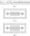
- optical fiber ferrules with five, seven, and nine rows of optical fiber holes (which are respectively shown in FIG. 4, FIG. 5 , and FIG. 6 ) and even a greater odd number of rows of optical fiber holes can be designed in this embodiment of this application, to ensure forward compatibility with other ferrules.
- the optical fiber ferrule with nine rows of optical fiber holes shown in FIG. 5 is compatible with the optical fiber ferrules with one, two, three, five, and seven rows of optical fiber holes.
- the diameter of the guide hole, the diameter of the optical fiber hole, and the inter-row center distance, and the distance between every two adjacent optical fiber holes in the same row are similar to those in FIG. 2c; and the corresponding parameters of the ferrule are set based on the diameter of the guide hole, the diameter of the optical fiber hole, and the inter-row center distance, and the distance between every two adjacent optical fiber holes in the same row.
- the optical fiber ferrule may be formed through injection molding.
- FIG. 7 is a schematic diagram showing compatibility of an optical fiber ferrule according to an embodiment of this application.
- the optical fiber ferrule with a plurality of optical fiber holes according to this application is forward compatible:
- the optical fiber ferrule with three rows of optical fiber holes is compatible with the optical fiber ferrule with one or two rows of optical fiber holes;
- the optical fiber ferrule with five rows of optical fiber holes is compatible with the optical fiber ferrule with one, two, or three rows of optical fiber holes;
- the optical fiber ferrule with seven rows of optical fiber holes is compatible with the optical fiber ferrule with one, two, three, or five rows of optical fiber holes;
- the optical fiber ferrule with nine rows of optical fiber holes is compatible with the optical fiber ferrule with one, two, three, five, or seven rows of optical fiber holes.
- the 36-core solution is fully compatible with the 12-core or 24-core optical fiber ferrule;
- the 60-core solution is compatible with the 12-core, 24-core, or 36-core optical fiber ferrule;
- the 84-core solution is compatible with the 12-core, 24-core, 36-core, or 60-core optical fiber ferrule;
- the 108-core solution is compatible with the 12-core, 24-core, 36-core, 60-core, and 84-core optical fiber ferule.
- the optical fiber ferrule with 12 optical fiber holes in each row is merely an example.
- the optical fiber ferrule may be designed to provide 16 or another number of optical fiber holes in each row as required.
- the optical fiber ferrule with five rows of optical fiber holes may be compatible with the optical fiber ferrule with two or four rows of optical fiber holes by setting the inter-row distance; the optical fiber ferrule with seven rows of optical fiber rows may be compatible with the optical fiber ferrule with two, four, or six rows of optical fiber holes by setting the inter-row distance; and the optical fiber ferrule with nine rows of optical fiber rows may be compatible with the optical fiber ferrule with two, four, six, or eight rows of optical fiber holes by setting the inter-row distance.
- the optical fiber ferrule of this application may be designed to be an optical fiber ferrule with an even number of rows of optical fiber holes that are symmetrically distributed in parallel.
- the center distances between every two adjacent rows of optical fiber holes in the optical fiber ferrules with different numbers of rows of optical fiber holes are the same or match with each other, and the rows of optical fiber holes are symmetrically distributed along the center-connecting line of the guide holes, so that the optical fiber ferrule with an even number of optical fiber holes is forward compatible, for example, the optical fiber ferrule with eight rows of optical fiber holes is compatible with the optical fiber ferrule with two, four, or six rows of optical fiber holes.
- FIG. 8 is a schematic structural diagram showing an optical fiber connector according to an embodiment of this application.
- the optical fiber connector includes a housing whose front end is a plug end, and in the housing, an optical fiber ferrule with guide holes or guide pins are fastened using a fastening member.
- the ferrule in the connector is the optical fiber ferrule mentioned in the foregoing embodiments of this application, and is configured to connect to a plurality of rows of optical fiber holes, to transmit optical signals.
- the ferrule is forward compatible with the previous-generation products with a smaller number of rows of optical fiber holes.
- the foregoing design mode can ensure that the product is forward compatible and improves product competitiveness.
- the previous-generation product can use an MT ferrule with a smaller number of rows of optical fiber holes to reduce costs, and the next-generation product can select an optical fiber ferrule with a greater number of rows of optical fiber holes based on the performance requirements to be compatible with the previous-generation product, thereby ensuring forward compatibility and improving product competitiveness.
Landscapes
- Physics & Mathematics (AREA)
- General Physics & Mathematics (AREA)
- Optics & Photonics (AREA)
- Mechanical Coupling Of Light Guides (AREA)
Abstract
Description
- This application claims priority to Chinese Patent Application No.
201820658536.6 - This application relates to the field of communications technologies, and in particular, to an optical fiber ferrule and an optical fiber connector.
- In the all-optical network connection solution, as the data transmission rate and the bandwidth are increasing, the requirement for the number of optical fiber connector cores becomes higher. A multi-core pluggable optical fiber connector commonly used in the art is an MPO (Multi-fiber Push On) optical fiber connector. Generally, 12-core optical fibers are arranged in a row to support one or more rows of optical fibers in the same connector, and are commonly used in high-density optical fiber connection systems. The MT (Monolithic Ferrule) ferrule is a core component in an MPO connector and is a mechanical docking transmission ferrule. The ferrule is multi-core and includes one or more rows of optical fiber holes for connecting and transmitting optical signals.
- With the increasing demand for MPO connectors and MT ferrule fiber cores, the number of cores in MT ferrule fibers in the industry currently evolves from 12 cores to 24 cores and then to 48 cores or from 16 cores to 32 cores. However, because the MT ferrule with a large number of fiber cores is incompatible with the MT ferrule with a small number of fiber cores, the future-generation products are incompatible with the previous-generation products.
- An embodiment of this application provides an optical fiber connector, which has high expandability and compatibility, and allows an optical fiber connector with a greater number of cores to be forward compatible with an optical fiber connector with a smaller number of cores.
- According to one aspect, this application provides an optical fiber ferrule, where n rows of optical fiber holes are distributed on a mating end face of the ferrule, n>=3; and the mating end face of the ferrule is provided with two guide holes, and a center-connecting line between the guide holes is provided with a row of optical fiber holes.
- Optionally, one of the n rows of optical fiber holes is distributed on the center-connecting line between the guide holes, and the other rows are symmetrically distributed on both sides of the center-connecting line.
- Optionally, n = 5, n = 7, or n = 9.
- According to another aspect, this application provides an optical fiber ferrule, where n rows of optical fiber holes are distributed on a mating end face of the ferrule, n>=3, and n is an odd number; and the mating end face of the ferrule is provided with two guide holes, and a center-connecting line between the guide holes is provided with a row of optical fiber holes.
- Optionally, one of the n rows of optical fiber holes is distributed on the center-connecting line between the guide holes, and the other rows are symmetrically distributed on both sides of the center-connecting line.
- Optionally, n = 5, n = 7, or n = 9.
- Optionally, a center distance between every two adjacent rows of optical fiber holes is 0.25 mm.
- Optionally, the guide hole is 0.69 mm or 0.50 mm.
- Optionally, there are 12 optical fiber holes in each odd row.
- Optionally, there are 16 optical fiber holes in each odd row.
- According to another aspect, this application provides an optical fiber ferrule, where n rows of optical fiber holes are symmetrically distributed on a mating end face of the ferrule, n>=3, and n is an even number; and the n rows of optical fiber holes are arranged parallel to each other.
- Optionally, the n rows of optical fiber holes are symmetrically distributed on both sides of the center-connecting line between the guide holes.
- Optionally, n = 2, n = 4, n = 6, or n = 8.
- According to another aspect, this application provides an optical fiber connector, where the optical fiber connector includes the optical fiber ferrule according to any of the foregoing implementations.
- Based on the layout design of optical fiber holes on the optical fiber ferrule, this application provides an optical fiber connector that includes a plurality of rows of optical fiber holes and that is compatible with one row and a relatively small number of rows of optical fiber holes, so that an optical fiber connector with a large number of cores can be forward compatible with an optical fiber connector with a small number of cores, thereby improving product expandability and compatibility.
-
-
FIG. 1a is a schematic diagram showing an arrangement of a group of optical fiber holes in a conventional optical fiber ferrule; -
FIG. 1b is a schematic diagram showing an arrangement of another group of optical fiber holes in a conventional optical fiber ferrule; -
FIG. 1c is a schematic diagram showing an arrangement of still another group of optical fiber holes in a conventional optical fiber ferrule; -
FIG. 2 is a schematic diagram showing an arrangement of optical fiber holes in an optical fiber ferrule according to an embodiment of this application; -
FIG. 3 is a schematic diagram showing compatibility of an optical fiber ferrule according to an embodiment of this application; -
FIG. 4 is a schematic diagram showing an arrangement of optical fiber holes in another optical fiber ferrule according to an embodiment of this application; -
FIG. 5 is a schematic diagram showing an arrangement of optical fiber holes in another optical fiber ferrule according to an embodiment of this application; -
FIG. 6 is a schematic diagram showing an arrangement of optical fiber holes in another optical fiber ferrule according to an embodiment of this application; -
FIG. 7 is a schematic diagram showing compatibility of an optical fiber ferrule according to an embodiment of this application; and -
FIG. 8 is a schematic structural diagram showing an optical fiber connector according to an embodiment of this application. -
FIG. 1a shows 12-core and 24-core MT ferrules in the prior art, where the 12-core MT ferrule is a first-generation product, and the 24-core MT ferrule solution is used when a subsequent product transmits a large amount of data. The technical solutions inFIG. 1a have the following problem: The subsequent 24-core ferrule features a symmetric distribution and is incompatible with a 12-core ferrule, so that the subsequent products are incompatible with the first-generation product. -
FIG. 1b shows 12-core, 24-core, and 48-core MT ferrule solutions in the prior art, where the 12-core and 24-core MT ferrules are first-generation products, and the 48-core MT ferrule is used when a subsequent product transmits a large amount of data. The technical solutions inFIG. 1b also have the foregoing problem: The subsequent 48-core ferrule features a symmetric distribution and is incompatible with a 12-core ferrule; in addition, the industry's common 48-core spacing is inconsistent with the 24-core spacing and is incompatible with the 24-core ferrule, so that the subsequent product is incompatible with the first-generation products. -
FIG. 1c shows 12-core, 16-core, and 32-core MT ferrules in the prior art, where the 12-core MT ferrule is a first-generation product, and the 16-core or 32-core MT ferrule solution is used when a subsequent product transmits a large amount of data. The technical solutions inFIG. 1c have the following problem: The diameter of each guide hole of the 16-core and 32-core MT ferrules is 0.5 mm, and the diameter of each guide hole of the 12-core MT ferrule is 0.6990 mm; because of the different diameters of the guide holes, the 16-core and 32-core MT ferrules are incompatible with the 12-core MT ferrule. In addition, because the 32-core MT ferrule features a symmetric distribution, the 32-core MT ferrule is incompatible with the 16-core MT ferrule. Consequently, the 32-core MT ferrule is incompatible with the 12-core and 16-core MT ferrules, and subsequent products are incompatible with the first-generation product. -
FIG. 2 is a schematic diagram of an arrangement of optical fiber holes in an optical fiber ferrule according to an embodiment of this application. As shown inFIG. 2 , the optical fiber ferrule is provided with three rows of through-going optical fiber holes on the mating end face, and the optical fiber ferrule is compatible with the optical fiber ferrules with one and two rows of optical fiber holes inFIG. 3 . The optical fiber ferrule with one row/two rows of optical fiber holes inFIG. 3 may be a 12-core/24-core MT ferrule in the prior art, or may be an optical fiber ferrule with one row/two rows of optical fiber holes of another specification. That is, to ensure that the optical fiber ferrule with three rows of optical fiber roles inFIG. 2 is compatible with the optical fiber ferrule with one or two rows of optical fiber holes inFIG. 3 , the distance C between the upper center-connecting line (that is, the center-connecting line of the upper row of optical fiber holes and the guide hole in the upper row) and the lower center-connecting line (that is, the center-connecting line of the lower row of optical fiber holes and the guide hole in the lower row), the distance B between every two adjacent optical fiber holes, and the number of optical fiber holes in each row are designed to correspond to the optical fiber ferrule with two rows of optical fiber holes; and the position and the distance between the optical fiber holes in the center-connecting line of the guide hole, and the number of optical fiber holes in each row may be designed to correspond to the optical fiber ferrule with one row of optical fiber holes; and the diameter D of the guide hole and the diameter A of the optical fiber hole are matched. - Specifically, when the MT ferrule with three rows of optical fiber holes in
FIG. 2 needs to be compatible with the 12-core and 24-core MT ferrules in the prior art, the diameter of the guide hole may be set to 0.6990 mm, and the center distance between every two adjacent rows of optical fiber holes may be set to half of that of the 24-core MT ferrule, that is, 0.25 mm. The diameter of the optical fiber hole and the distance between every two adjacent optical fiber holes in the same row are the same as those of the 12-core and 24-core MT ferrules. The number of optical fiber holes in each row is 12, and the three rows of optical fiber holes are symmetrically distributed along the center axis of the guide holes. In addition, the optical fiber holes are symmetrically distributed along the midperpendicular of the center axis of the guide holes. - The foregoing description is only a specific example. Values such as the number of optical fiber holes in each row, the diameter of the guide hole, the center distance between every two adjacent rows of optical fiber holes, and the distance between the holes in the same row, can be set to values different from the foregoing values as required, so as to ensure compatibility with the desired optical fiber ferrule.
- The optical fiber ferrule in
FIG. 2 may be formed through injection molding. - According to the foregoing optical fiber ferrule having three rows of through-going optical fiber holes, when the first-generation product uses an optical fiber ferrule with one or two rows of optical fiber holes to reduce costs, the second-generation product can select an optical fiber ferrule with three rows of optical fiber holes shown in
FIG. 2 based on the performance requirements, so as to ensure forward compatibility and improve product competitiveness. - In addition to the optical fiber ferrule with three rows of optical fiber holes in
FIG. 2 , when the transmission rate and bandwidth requirements become higher, optical fiber ferrules with five, seven, and nine rows of optical fiber holes (which are respectively shown inFIG. 4, FIG. 5 , andFIG. 6 ) and even a greater odd number of rows of optical fiber holes can be designed in this embodiment of this application, to ensure forward compatibility with other ferrules. For example, the optical fiber ferrule with nine rows of optical fiber holes shown inFIG. 5 is compatible with the optical fiber ferrules with one, two, three, five, and seven rows of optical fiber holes. - The diameter of the guide hole, the diameter of the optical fiber hole, and the inter-row center distance, and the distance between every two adjacent optical fiber holes in the same row are similar to those in FIG. 2c; and the corresponding parameters of the ferrule are set based on the diameter of the guide hole, the diameter of the optical fiber hole, and the inter-row center distance, and the distance between every two adjacent optical fiber holes in the same row.
- Likewise, the optical fiber ferrule may be formed through injection molding.
-
FIG. 7 is a schematic diagram showing compatibility of an optical fiber ferrule according to an embodiment of this application. The optical fiber ferrule with a plurality of optical fiber holes according to this application is forward compatible: The optical fiber ferrule with three rows of optical fiber holes is compatible with the optical fiber ferrule with one or two rows of optical fiber holes; the optical fiber ferrule with five rows of optical fiber holes is compatible with the optical fiber ferrule with one, two, or three rows of optical fiber holes; the optical fiber ferrule with seven rows of optical fiber holes is compatible with the optical fiber ferrule with one, two, three, or five rows of optical fiber holes; and the optical fiber ferrule with nine rows of optical fiber holes is compatible with the optical fiber ferrule with one, two, three, five, or seven rows of optical fiber holes. For example, using the optical fiber ferrule with 12 optical fiber roles in each row as an example, the 36-core solution is fully compatible with the 12-core or 24-core optical fiber ferrule; the 60-core solution is compatible with the 12-core, 24-core, or 36-core optical fiber ferrule; the 84-core solution is compatible with the 12-core, 24-core, 36-core, or 60-core optical fiber ferrule; and the 108-core solution is compatible with the 12-core, 24-core, 36-core, 60-core, and 84-core optical fiber ferule. The optical fiber ferrule with 12 optical fiber holes in each row is merely an example. The optical fiber ferrule may be designed to provide 16 or another number of optical fiber holes in each row as required. - In addition to the foregoing compatibility, the optical fiber ferrule with five rows of optical fiber holes may be compatible with the optical fiber ferrule with two or four rows of optical fiber holes by setting the inter-row distance; the optical fiber ferrule with seven rows of optical fiber rows may be compatible with the optical fiber ferrule with two, four, or six rows of optical fiber holes by setting the inter-row distance; and the optical fiber ferrule with nine rows of optical fiber rows may be compatible with the optical fiber ferrule with two, four, six, or eight rows of optical fiber holes by setting the inter-row distance.
- In addition to the foregoing embodiments, the optical fiber ferrule of this application may be designed to be an optical fiber ferrule with an even number of rows of optical fiber holes that are symmetrically distributed in parallel. For example, for the optical fiber ferrule with two, four, six, or eight rows of optical fiber holes, the center distances between every two adjacent rows of optical fiber holes in the optical fiber ferrules with different numbers of rows of optical fiber holes are the same or match with each other, and the rows of optical fiber holes are symmetrically distributed along the center-connecting line of the guide holes, so that the optical fiber ferrule with an even number of optical fiber holes is forward compatible, for example, the optical fiber ferrule with eight rows of optical fiber holes is compatible with the optical fiber ferrule with two, four, or six rows of optical fiber holes.
-
FIG. 8 is a schematic structural diagram showing an optical fiber connector according to an embodiment of this application. As shown inFIG. 8 , the optical fiber connector includes a housing whose front end is a plug end, and in the housing, an optical fiber ferrule with guide holes or guide pins are fastened using a fastening member. The ferrule in the connector is the optical fiber ferrule mentioned in the foregoing embodiments of this application, and is configured to connect to a plurality of rows of optical fiber holes, to transmit optical signals. The ferrule is forward compatible with the previous-generation products with a smaller number of rows of optical fiber holes. - The foregoing design mode can ensure that the product is forward compatible and improves product competitiveness. The previous-generation product can use an MT ferrule with a smaller number of rows of optical fiber holes to reduce costs, and the next-generation product can select an optical fiber ferrule with a greater number of rows of optical fiber holes based on the performance requirements to be compatible with the previous-generation product, thereby ensuring forward compatibility and improving product competitiveness.
Claims (9)
- An optical fiber ferrule, wherein n rows of optical fiber holes are symmetrically distributed on a mating end face of the ferrule, n>=3, and n is an odd number; and the n rows of optical fiber holes are arranged parallel to each other.
- The optical fiber ferrule according to claim 1, wherein the mating end face of the ferrule is provided with two guide holes, and a center-connecting line between the guide holes is provided with a row of optical fiber holes.
- The optical fiber ferrule according to claim 1 or 2, wherein the odd number of rows of optical fiber holes are symmetrically distributed along the center-connecting line between the guide holes.
- The optical fiber ferrule according to any one of claims 1 to 3, wherein the odd number of rows of optical fiber holes comprise 3 rows of optical fiber holes.
- The optical fiber ferrule according to any one of claims 1 to 3, wherein the odd number of rows of optical fiber holes comprise 5 rows of optical holes.
- The optical fiber ferrule according to any one of claims 1 to 3, wherein a center distance between every two adjacent rows of optical fiber holes is 0.25 mm.
- The optical fiber ferrule according to any one of claims 1 to 5, wherein each row of the odd number of rows of the optical fiber holes comprises 12 optional fiber holes.
- The optical fiber ferrule according to any one of claims 1 to 5, wherein each row of the odd number of rows of the optical fiber holes comprises 16 optional fiber holes.
- An optical fiber connector, wherein the optical fiber connector comprises a housing whose front end is a plug end; and in the housing, the optical fiber ferrule according to any one of claims 1 to 8 is fastened by a fastening member.
Applications Claiming Priority (2)
| Application Number | Priority Date | Filing Date | Title |
|---|---|---|---|
| CN201820658536.6U CN208737044U (en) | 2018-05-04 | 2018-05-04 | A kind of fiber stub, optical fiber connector |
| PCT/CN2019/081633 WO2019210763A1 (en) | 2018-05-04 | 2019-04-06 | Optical fiber ferrule and optical fiber connector |
Publications (2)
| Publication Number | Publication Date |
|---|---|
| EP3761090A1 true EP3761090A1 (en) | 2021-01-06 |
| EP3761090A4 EP3761090A4 (en) | 2021-04-28 |
Family
ID=66024269
Family Applications (1)
| Application Number | Title | Priority Date | Filing Date |
|---|---|---|---|
| EP19796422.4A Pending EP3761090A4 (en) | 2018-05-04 | 2019-04-06 | FIBER SLEEVE AND FIBERGLASS CONNECTOR |
Country Status (4)
| Country | Link |
|---|---|
| US (2) | US11619786B2 (en) |
| EP (1) | EP3761090A4 (en) |
| CN (1) | CN208737044U (en) |
| WO (1) | WO2019210763A1 (en) |
Families Citing this family (6)
| Publication number | Priority date | Publication date | Assignee | Title |
|---|---|---|---|---|
| CN110333575A (en) * | 2019-06-11 | 2019-10-15 | 华为技术有限公司 | A kind of fiber stub and multi-fiber connector |
| CN116125605A (en) * | 2020-04-17 | 2023-05-16 | 华为技术有限公司 | Optical connector lock pin and optical connector |
| CN114063218B (en) * | 2020-07-31 | 2023-01-06 | 华为技术有限公司 | Optical fiber ferrule and communication equipment |
| CN116057440B (en) * | 2020-11-17 | 2025-06-06 | 株式会社藤仓 | cap |
| JP7657699B2 (en) * | 2021-10-28 | 2025-04-07 | 株式会社白山 | Optical circuit mounting board, computer, and optical connection method |
| CN114460694B (en) * | 2021-12-09 | 2023-10-20 | 华为技术有限公司 | An optical module, ferrule and optical fiber connector |
Family Cites Families (9)
| Publication number | Priority date | Publication date | Assignee | Title |
|---|---|---|---|---|
| US6843606B2 (en) * | 2000-11-14 | 2005-01-18 | National Semiconductor Corporation | Multi-format connector module incorporating chip mounted optical sub-assembly |
| US6802653B2 (en) * | 2000-11-14 | 2004-10-12 | National Semiconductor Corporation | Method and apparatus for adapting a miniature form-factor connector to a standard format fiber optic connector plug |
| US6604866B1 (en) * | 2002-03-04 | 2003-08-12 | Xanoptix, Inc. | Optical fiber ferrule |
| US6913397B2 (en) * | 2002-03-04 | 2005-07-05 | Xanoptix, Inc. | Method and system for insertion of fibers of a fiber cable into a ferrule |
| US7588374B2 (en) * | 2007-10-05 | 2009-09-15 | Fujikura Ltd. | Optical ferrule and manufacturing method thereof |
| US9551841B2 (en) * | 2012-11-30 | 2017-01-24 | Corning Optical Communications LLC | Optical data center connector systems, fiber optic plug assemblies, and fiber optic receptacle assemblies |
| US10162127B2 (en) * | 2013-10-15 | 2018-12-25 | Commscope, Inc. Of North Carolina | Expanded beam array for fiber optics |
| JP2016057483A (en) * | 2014-09-10 | 2016-04-21 | 住友電気工業株式会社 | Connector ferrule |
| US10401576B2 (en) * | 2017-05-10 | 2019-09-03 | Senko Advanced Components, Inc. | MPO micro-latch-lock connector |
-
2018
- 2018-05-04 CN CN201820658536.6U patent/CN208737044U/en active Active
-
2019
- 2019-04-06 EP EP19796422.4A patent/EP3761090A4/en active Pending
- 2019-04-06 WO PCT/CN2019/081633 patent/WO2019210763A1/en not_active Ceased
-
2020
- 2020-09-29 US US17/037,355 patent/US11619786B2/en active Active
-
2023
- 2023-03-15 US US18/184,143 patent/US20230288647A1/en not_active Abandoned
Also Published As
| Publication number | Publication date |
|---|---|
| WO2019210763A1 (en) | 2019-11-07 |
| US20210018701A1 (en) | 2021-01-21 |
| US20230288647A1 (en) | 2023-09-14 |
| US11619786B2 (en) | 2023-04-04 |
| EP3761090A4 (en) | 2021-04-28 |
| CN208737044U (en) | 2019-04-12 |
Similar Documents
| Publication | Publication Date | Title |
|---|---|---|
| US20230288647A1 (en) | Optical fiber ferrule and optical fiber connector | |
| US20230071065A1 (en) | Adapter system for multi-fiber mechanical transfer type ferrule | |
| US9535221B2 (en) | UltraHigh-density fiber distribution components | |
| EP3482243B1 (en) | Polarity changeable connector | |
| US9983362B2 (en) | High density optical packaging header apparatus | |
| US10139572B2 (en) | Duplex fiber optic components suitable for polarity reversal | |
| US7218828B2 (en) | Optical fiber power splitter module apparatus | |
| US20140241689A1 (en) | Ganged fiber optic connector adapter modules and assemblies having reinforcement members and staggered fiber optic connector adapter ports | |
| CN111221083B (en) | Multi-core optical fiber single-core connector and preparation and alignment method thereof | |
| US20130051733A1 (en) | Apparatus and Method for Ganged Multiple Optical Fiber Connector | |
| US20060275007A1 (en) | Optical fiber array connectivity system with indicia to facilitate connectivity in four orientations for dual functionality | |
| US20140140660A1 (en) | Polarity scheme for parallel-optics data transmission | |
| US20120057824A1 (en) | Optical connector and optical communication system | |
| EP4130825A1 (en) | Optical connector ferrule and optical connector | |
| US20110249943A1 (en) | Gender-neutral mpo connectors | |
| US20170192182A1 (en) | Method And System For A Multi-Fiber Push-On/Pull-Off Connector Locking Clip | |
| JP2012530936A5 (en) | ||
| EP3564721A1 (en) | Angle polished multi-fiber connector | |
| US10031298B2 (en) | Extended access optical fiber connector ferrule | |
| US20260003137A1 (en) | Adapter to Jacketed Fiber Interface | |
| US20250251552A1 (en) | Cable assembly | |
| US10788628B2 (en) | Multi-fiber fiber optic connector | |
| US11555967B2 (en) | Fiber connection structure provided with optical connector, module, and assembly | |
| Thakur | Mpo Breakout Cable: Understanding Its Functionality, Benefits | |
| CN114167551A (en) | Connector for multiple optical fibers |
Legal Events
| Date | Code | Title | Description |
|---|---|---|---|
| STAA | Information on the status of an ep patent application or granted ep patent |
Free format text: STATUS: THE INTERNATIONAL PUBLICATION HAS BEEN MADE |
|
| PUAI | Public reference made under article 153(3) epc to a published international application that has entered the european phase |
Free format text: ORIGINAL CODE: 0009012 |
|
| STAA | Information on the status of an ep patent application or granted ep patent |
Free format text: STATUS: REQUEST FOR EXAMINATION WAS MADE |
|
| 17P | Request for examination filed |
Effective date: 20201001 |
|
| AK | Designated contracting states |
Kind code of ref document: A1 Designated state(s): AL AT BE BG CH CY CZ DE DK EE ES FI FR GB GR HR HU IE IS IT LI LT LU LV MC MK MT NL NO PL PT RO RS SE SI SK SM TR |
|
| AX | Request for extension of the european patent |
Extension state: BA ME |
|
| A4 | Supplementary search report drawn up and despatched |
Effective date: 20210331 |
|
| RIC1 | Information provided on ipc code assigned before grant |
Ipc: G02B 6/38 20060101AFI20210325BHEP |
|
| DAV | Request for validation of the european patent (deleted) | ||
| DAX | Request for extension of the european patent (deleted) | ||
| STAA | Information on the status of an ep patent application or granted ep patent |
Free format text: STATUS: EXAMINATION IS IN PROGRESS |
|
| 17Q | First examination report despatched |
Effective date: 20231009 |