EP3761019B1 - Compensator circuitry and method for an oxygen sensor - Google Patents
Compensator circuitry and method for an oxygen sensor Download PDFInfo
- Publication number
- EP3761019B1 EP3761019B1 EP20183600.4A EP20183600A EP3761019B1 EP 3761019 B1 EP3761019 B1 EP 3761019B1 EP 20183600 A EP20183600 A EP 20183600A EP 3761019 B1 EP3761019 B1 EP 3761019B1
- Authority
- EP
- European Patent Office
- Prior art keywords
- compensator
- digital
- output
- cell
- circuitry
- Prior art date
- Legal status (The legal status is an assumption and is not a legal conclusion. Google has not performed a legal analysis and makes no representation as to the accuracy of the status listed.)
- Active
Links
Images

Classifications
-
- F—MECHANICAL ENGINEERING; LIGHTING; HEATING; WEAPONS; BLASTING
- F02—COMBUSTION ENGINES; HOT-GAS OR COMBUSTION-PRODUCT ENGINE PLANTS
- F02D—CONTROLLING COMBUSTION ENGINES
- F02D41/00—Electrical control of supply of combustible mixture or its constituents
- F02D41/02—Circuit arrangements for generating control signals
- F02D41/14—Introducing closed-loop corrections
- F02D41/1438—Introducing closed-loop corrections using means for determining characteristics of the combustion gases; Sensors therefor
- F02D41/1493—Details
- F02D41/1494—Control of sensor heater
-
- H—ELECTRICITY
- H03—ELECTRONIC CIRCUITRY
- H03K—PULSE TECHNIQUE
- H03K7/00—Modulating pulses with a continuously-variable modulating signal
- H03K7/08—Duration or width modulation ; Duty cycle modulation
-
- F—MECHANICAL ENGINEERING; LIGHTING; HEATING; WEAPONS; BLASTING
- F01—MACHINES OR ENGINES IN GENERAL; ENGINE PLANTS IN GENERAL; STEAM ENGINES
- F01N—GAS-FLOW SILENCERS OR EXHAUST APPARATUS FOR MACHINES OR ENGINES IN GENERAL; GAS-FLOW SILENCERS OR EXHAUST APPARATUS FOR INTERNAL-COMBUSTION ENGINES
- F01N11/00—Monitoring or diagnostic devices for exhaust-gas treatment apparatus
- F01N11/007—Monitoring or diagnostic devices for exhaust-gas treatment apparatus the diagnostic devices measuring oxygen or air concentration downstream of the exhaust apparatus
-
- F—MECHANICAL ENGINEERING; LIGHTING; HEATING; WEAPONS; BLASTING
- F02—COMBUSTION ENGINES; HOT-GAS OR COMBUSTION-PRODUCT ENGINE PLANTS
- F02D—CONTROLLING COMBUSTION ENGINES
- F02D41/00—Electrical control of supply of combustible mixture or its constituents
- F02D41/02—Circuit arrangements for generating control signals
- F02D41/14—Introducing closed-loop corrections
- F02D41/1438—Introducing closed-loop corrections using means for determining characteristics of the combustion gases; Sensors therefor
- F02D41/1444—Introducing closed-loop corrections using means for determining characteristics of the combustion gases; Sensors therefor characterised by the characteristics of the combustion gases
- F02D41/1446—Introducing closed-loop corrections using means for determining characteristics of the combustion gases; Sensors therefor characterised by the characteristics of the combustion gases the characteristics being exhaust temperatures
-
- F—MECHANICAL ENGINEERING; LIGHTING; HEATING; WEAPONS; BLASTING
- F02—COMBUSTION ENGINES; HOT-GAS OR COMBUSTION-PRODUCT ENGINE PLANTS
- F02D—CONTROLLING COMBUSTION ENGINES
- F02D41/00—Electrical control of supply of combustible mixture or its constituents
- F02D41/02—Circuit arrangements for generating control signals
- F02D41/14—Introducing closed-loop corrections
- F02D41/1438—Introducing closed-loop corrections using means for determining characteristics of the combustion gases; Sensors therefor
- F02D41/1444—Introducing closed-loop corrections using means for determining characteristics of the combustion gases; Sensors therefor characterised by the characteristics of the combustion gases
- F02D41/1454—Introducing closed-loop corrections using means for determining characteristics of the combustion gases; Sensors therefor characterised by the characteristics of the combustion gases the characteristics being an oxygen content or concentration or the air-fuel ratio
-
- F—MECHANICAL ENGINEERING; LIGHTING; HEATING; WEAPONS; BLASTING
- F02—COMBUSTION ENGINES; HOT-GAS OR COMBUSTION-PRODUCT ENGINE PLANTS
- F02D—CONTROLLING COMBUSTION ENGINES
- F02D41/00—Electrical control of supply of combustible mixture or its constituents
- F02D41/02—Circuit arrangements for generating control signals
- F02D41/14—Introducing closed-loop corrections
- F02D41/1438—Introducing closed-loop corrections using means for determining characteristics of the combustion gases; Sensors therefor
- F02D41/1493—Details
- F02D41/1495—Detection of abnormalities in the air/fuel ratio feedback system
-
- G—PHYSICS
- G01—MEASURING; TESTING
- G01N—INVESTIGATING OR ANALYSING MATERIALS BY DETERMINING THEIR CHEMICAL OR PHYSICAL PROPERTIES
- G01N27/00—Investigating or analysing materials by the use of electric, electrochemical, or magnetic means
- G01N27/26—Investigating or analysing materials by the use of electric, electrochemical, or magnetic means by investigating electrochemical variables; by using electrolysis or electrophoresis
- G01N27/403—Cells and electrode assemblies
- G01N27/406—Cells and probes with solid electrolytes
- G01N27/4065—Circuit arrangements specially adapted therefor
-
- F—MECHANICAL ENGINEERING; LIGHTING; HEATING; WEAPONS; BLASTING
- F02—COMBUSTION ENGINES; HOT-GAS OR COMBUSTION-PRODUCT ENGINE PLANTS
- F02D—CONTROLLING COMBUSTION ENGINES
- F02D41/00—Electrical control of supply of combustible mixture or its constituents
- F02D41/20—Output circuits, e.g. for controlling currents in command coils
- F02D2041/202—Output circuits, e.g. for controlling currents in command coils characterised by the control of the circuit
- F02D2041/2024—Output circuits, e.g. for controlling currents in command coils characterised by the control of the circuit the control switching a load after time-on and time-off pulses
- F02D2041/2027—Control of the current by pulse width modulation or duty cycle control
-
- F—MECHANICAL ENGINEERING; LIGHTING; HEATING; WEAPONS; BLASTING
- F02—COMBUSTION ENGINES; HOT-GAS OR COMBUSTION-PRODUCT ENGINE PLANTS
- F02D—CONTROLLING COMBUSTION ENGINES
- F02D41/00—Electrical control of supply of combustible mixture or its constituents
- F02D41/24—Electrical control of supply of combustible mixture or its constituents characterised by the use of digital means
- F02D41/26—Electrical control of supply of combustible mixture or its constituents characterised by the use of digital means using computer, e.g. microprocessor
- F02D41/28—Interface circuits
- F02D2041/281—Interface circuits between sensors and control unit
Definitions
- This invention relates to wide range oxygen (O2) sensors, and typically such sensors are used in vehicle systems to determine oxygen levels in e.g. exhausts. Such sensors are often referred to as lambda sensors. It particularly relates to circuitry used to operate such oxygen sensors.
- the circuitry may e.g. be embodied on a chip connected to a microprocessor and the sensor.
- an O2 sensor is mounted in the exhaust system of an engine to monitor how much unburned fuel or excess oxygen is in the exhaust as the exhaust gas exits the engine. Monitoring oxygen levels in the exhaust is a way of gauging the fuel mixture.
- An O2 or lambda sensor is based on solid-state electrochemical reactions.
- the sensor can be constructed of one or two cells. When coupled to an appropriate electrical interface, a current is produced that varies approximately linearly with the partial pressure of oxygen in the exhaust gas relative to that in the atmosphere.
- the temperature of the sensor In wide-range air fuel sensors, the temperature of the sensor must be tightly controlled at temperatures of around 750C. This temperature is achieved by use of a resistive ceramic heating element within the sensor. Typically, cell impedance measurements are performed on an O2 Sensor in order to estimate its temperature. This temperature is subtracted from a desired temperature to provide an error value. This error term can be used as an input to a control loop that varies the PWM duty cycle of battery voltage applied across an e.g. ceramic heating element embedded in the sensor. This control loop seeks to maintain the temperature error at a low value.
- the temperature of the sensor must be tightly controlled at temperatures of around 750C.
- This temperature is achieved by use of a resistive ceramic heating element within the sensor. This element is capable of heating the sensor from ambient alone or by supplementing the engine exhaust heat.
- the automotive 12V battery voltage is applied across the element in a pulse width modulated fashion.
- the impedance of the sensor reference cell is measured and used to indicate the temperature of the sensor.
- a control loop is utilized to modify the PWM duty cycle to adjust the amount of heating to maintain the desired temperature.
- the PWM control of the ceramic heater can disrupt the closed loop control of the reference and pump cells of the sensor. This results in the PWM switching edges causing pump cell current errors for an extended period of time after the edge. This limits the ability to use the sensor where engine synchronous pump current readings are desired.
- this cable contains six wires which include: reference, sensor common, pump, tag, heater+ and heater-. Due to the nature of the heating element, the PWM control of the sensor's heater causes large DV/DT's and large DI/DT's in the heater wires within the cable as well as within the sensor itself. The current in the heater can be on the order of a few amps. This can couple noise onto the other wires in the cable.
- a compensator circuitry for an oxygen sensor, said oxygen sensor including a pump cell and a reference cell, said compensator circuitry including a feedback control loop configured to maintain the reference cell at a reference voltage, said feedback control loop including a digital compensator, configured to determine and output a compensation current to said pump cell dependent on a reference voltage measured from said reference cell, and further configured to suspend the determination and output of said compensation current for a set time dependent on detection of edges in an oxygen sensor heater Pulse Width Modulation (PWM) signal and including means to detect a rising or falling edge of said PWM signal.
- PWM Pulse Width Modulation
- Said digital compensator may be programmable.
- Said set time may be programmable.
- the compensator circuitry may be configured to suspend the determination and/or output of said compensation current for a set time subsequent to detection of a rising or falling edge of said PWM signal.
- the compensator circuitry includes means to detect a rising or falling edge of said PWM signal.
- the compensator circuitry including means to provide a suspend signal or time of programmable length subsequent to the detection of a rising or falling edge of said PWM signal.
- the compensator circuitry may be further configured to convert the measured reference voltage of the reference cell to a digital quantity, and further configured to digitally compare this with a digital reference value, so as to provide a digital comparison for said digital compensator, where said compensation current is determined from said digital comparison.
- the compensator circuitry may further include means to determine the compensation current to be output to the pump cell, and convert this to a digital value.
- the circuitry may be configured to suspend the determination and output of said compensation current by being configured to suspend receiving the input derived from said reference cell and/or suspend the determination and/or output of the output current.
- an oxygen sensor system including an oxygen sensor, said oxygen sensor including a pump cell and a reference cell, and including a heater means configured to receive a PWM signal to control said heater, and compensator circuitry as above connected to said oxygen sensor.
- a method of operating compensator circuitry for an oxygen sensor said oxygen sensor including a pump cell and a reference cell, said compensator circuitry including a feedback control loop adapted to maintain the reference cell at a reference voltage, said feedback control loop including a digital compensator, configured to determine and output a compensation current to said pump cell dependent on a reference voltage measured from said reference cell, said method including: a) detecting edges in an oxygen sensor heater Pulse Width Modulation (PWM) signal; b) suspending determination and output of said compensation current for a set time dependent on step a).
- PWM Pulse Width Modulation
- Said set time may be programmable.
- Step a) may comprise suspending the determination and/or output of said compensation current for a set time subsequent to detection of a rising or falling edge of said PWM signal.
- the method may include providing a suspend signal or suspend signal time of programmable amount subsequent to the detection of a rising or falling edge of said PWM signal.
- the method may include the steps of converting the measured reference voltage of the reference cell to a digital quantity, and digitally comparing this with a digital reference value, providing a digital comparison to said digital compensator, and determining said compensation current from said digital comparison.
- Step b) may comprise suspending the receiving of input derived from said reference cell and/or suspending the determination and or output of the output current.
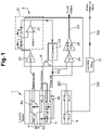
- Figure 1 shows a schematic view of a known O2 sensor system - it shows the 2-cell O2 sensor 1.
- a sensor interface IC 2 generally interfaces between the sensor and a microprocessor (not shown). Tasks of the microprocessor include converting the pump current readings from the sensor interface IC 2 to air/fuel ratio along with reading the sensor impedance related measurements made by the sensor interface IC 2 and adjusting the heater PWM to control temperature.
- any functionality of the sensor interface IC 2 may be performed by the microprocessor and vice versa.
- the sensor On the left hand side is shown the sensor itself which is a 2-cell sensor known in the art.
- the sensor (element) includes a measurement or reference (REF) cell 4 and a pump cell 5.
- the two cells 4, 5 are separated on sides by a porous diffusion component 6 (which provides/defines a porous diffusion passage) so as to form a gas detecting cavity 7.
- Electrodes 8 a, b, c, d are located on either side of the cells 4, 5 and provide appropriate input and outputs to the other parts (circuitry) of the system.
- a heater 9 Adjacent to the O2 sensor is a heater 9 such as a ceramic heater. This is connected by one line to a battery (vehicle battery) and controlled by a microprocessor (not shown) via a Low Side Driver 10 and heater wire(s) 100. Driving the high side instead of the low side is acceptable, as is controlling both sides with the microprocessor.
- the electrodes 8 a, b, c, d of the two cells 4, 5 are connected to the sensor interface IC 2/circuitry, the sensor interface IC 2 has input and output connections to the microprocessor not shown which is used to measure and process the inputs from the electrodes (via the sensor interface IC 2) as well as output to control the voltages of the electrodes 8b and 8c via FET 16.
- the lines from the microprocessor to the FET 16 are not shown.
- a two cell O2 sensor is controlled by two control loops, one maintains the proper sensor voltage/current bias while the other maintains the sensor temperature.
- the proper O2 sensor bias is controlled by adjusting the pump current (i.e. the current through the pump cell 5) in order to maintain the reference cell voltage (e.g. electrode 8a) at e.g., 450mV.
- the figure shows the bias control circuit portion of the intermediate IC/circuitry which implements a transfer function specified by the manufacturer for a specific sensor model to insure proper loop performance.
- the temperature control is accomplished by measuring the reference cell impedance to determine temperature along with applying Pulse Width Modulation of the battery voltage across the ceramic heater to apply power.
- the primary control of a two cell O2 sensor 1 involves applying the reference cell voltage to a compensator network which is tasked with the primary control.
- Reference numeral 2 shows the functionality of the sensor interface IC with regard to the compensator network i.e. the bias control circuitry.
- the compensator includes a connection from electrode 8a to the unity gain amplifier 22.
- the output of the unity gain amplifier 22 is connected to one input of an operational amplifier circuit 20.
- the other input to operational amplifier circuit 20 is connected to a voltage of (e.g., 450mV).
- Operational amplifier circuit 20, comprised of discrete resistors, capacitors and operational amplifier 21, implements a desired transfer function to stabilize this control loop.
- the output of the operational amplifier circuit 20 is connected to a voltage to current converter 23 which adjusts the current into the pump cell 5 via electrode 8d dependent on the voltage output from operational amplifier circuit 20.
- the current into the pump cell 5 modifies consequently the reference voltage which the loop maintains at e.g., 450mV.
- the value of the pump current that is required to achieve 450mV of reference voltage is dependent on the O2 concentration in the exhaust gases.
- the pump current is measured by measuring the voltage across resistor R1 by unity gain amplifier 24 which is then amplified by appropriate scaling amplifier 25, the output of which is sent to the microprocessor along line 101 - the microprocessor converts this signal representing O2 concentration to an air/fuel (A/F) ratio.
- this compensator in previous art, is an analog compensator implementing the transfer function with operational amplifiers and external resistors and capacitors.
- the secondary control is the sensor temperature control loop described previously.
- a problem is that when the transient voltage and currents on the heater wires 100 couple into the reference cell, this is disruptive to the primary control loop since it shows up as a deviation from the desired reference cell voltage of 450mV. Due to the nature of the control loop, this disruption causes a variation in the pump current as the loop tries to correct for the reference cell noise. Eventually the loop will recover from the noise and return to its steady state, but in the meantime the pump current is in error and in turn causes the A/F ratio to be in error.
- the wires for the heater are located in the same wire harness as the reference and pump cell wires. Coupling between the heater wires and the reference and common wires can cause a periodic disruption in the reference voltage which disturbs the control loop. (Coupling occurs within the sensor itself as well.)
- Figure 2 shows a scope plot of the disturbance caused by a PWM edge coupling onto the reference cell which causes a pump cell current disturbance, i.e. the pump current disruption due to a PWM edge.
- the pump current disturbance was around 130 ⁇ A and lasted around 400 ⁇ s.
- the figure shows the pump current 30, the heater voltage/current 31 with switching edge 32 and the reference cell voltage 33.
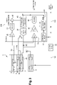
- FIG. 3 shows an example of the invention which shows a design of the compensator circuitry according to one example.
- the compensator is implemented digitally. This allows for a flexible O2 sensor control IC with a digital compensator.
- This provides several benefits, one of which is that the compensator transfer function is programmable via a Serial Peripheral Interface (SPI) allowing a given hardware configuration to be compatible with a multitude of sensors.
- SPI Serial Peripheral Interface
- the input from electrode 8a again goes through a unity gain amplifier 22 and is then input to an analog to digital converter (ADC) 41 where the voltage level is converted to a digital quantity.
- ADC analog to digital converter
- a bit sequence which is the binary equivalent to e.g., 450mV (the nominal voltage of the reference cell) is subtracted from the output of ADC 41 via the digital subtractor circuit 42.
- the output of the subtractor circuit is then fed to a digital programmable compensator 43 which may be a 3rd order compensator in one example.
- the output of the digital programmable compensator 43 is connected to the current DAC 44.
- the current DAC 44 is connected through R1 to the pump cell electrode 8d and outputs current to the pump cell to maintain the reference cell voltage at 450mV.
- the output of the current DAC 44 provides the requisite current to the pump cell via electrode 8d to maintain the primary control i.e. to provide the appropriate sensor voltage/current bias.
- the current to the pump cell 5 i.e. to electrode 8d may be determined in a similar fashion to figure 1 again by looking at the voltage across resistor R1, where this voltage across the resistor is again fed to a unity gain amplifier 24, the output of which is further amplified by a programmable gain amplifier 45.
- Programmable gain amplifier 45 in this example has programmable gains of 1, 2, 4, or 8 and its output is fed to analog to digital converter ADC 46. The digital output of this converter is read by the microprocessor.
- a conditioned heater PWM signal (from the microprocessor) to the digital programmable compensator 43.
- a PWM edge detection circuit/function block 47 where the PWM heater signal is fed from line 102 from the microprocessor output to the heater Low Side Drive 10 and to PWM edge detection block 47.
- Low Side Driver 10 may be incorporated into sensor interface IC 200 or may be a whole, or part of, a separate integrated circuit.
- the PWM edge detection block 47 detects edges (i.e. rising or falling edges) of the PWM signal; i.e. the heater switching edge (e.g. low to high or high to low) is detected.
- the output of PWM edge detection block 47 is connected to a Programmable Park Width circuit 48 (a programmable Park signal generator) which determines a "park" or suspend time signal which is of programmable and variable time (and which starts on the detection of the edges detected by PWM edge detection block 47) which is fed to the digital programmable compensator 43.
- the digital programmable compensator 43 puts on hold certain processes during the park time, to avoid disruption from the edges.
- the compensator unit resumes normal operation. While the digital compensator is parked, the pump current is held constant at whatever value it was at prior to the park signal becoming active.
- the digital programmable compensator 43 When the digital programmable compensator 43 receives the "park" command or “park” signal, it no longer accepts A/D convertor inputs from ADC 41/ digital subtractor circuit 42, and freezes the computation of the transfer function. Upon expiration of the park command/signal, the digital programmable compensator 43 resumes normal operation. This effectively masks the noise from entering the digital programmable compensator. 43 Another benefit relates to the problem of disruption of the primary control loop due to PWM edge noise.
- the circuitry of this invention senses the heater PWM edge and "parks" the digital programmable compensator 43 for a programmable amount of time in order to prevent the reference cell disturbance from perturbing the control loop. Parking and resuming the digital programmable compensator 43 involves carefully pausing and restarting the digital programmable compensator 43 with respect to the ADC updates. This greatly reduces the pump current disturbance allowing for improved engine synchronous pump current (A/F ratio) readings.
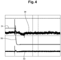
- figure 4 is similar to figure 2 and shows the pump current 30, the heater voltage/current 31 with switching edge 32 and reference cell voltage and shows the respective waveforms where the compensator was parked for a fixed period of time at the PWM edge.
- Figure 4 shows the pump current disruption when the digital compensator is parked upon the PWM edge. The error in pump current was reduced to 25 ⁇ A with a duration of less than 200 ⁇ s.
- any functionality of the sensor interface IC 200 may be performed by the microprocessor and vice versa.
- any of the functionality of ADC 41 and/or digital subtractor circuit 42 may be incorporated into the digital programmable compensator 43.
- any of the functionality of PWM edge detection block 47 and or Programmable Park Width circuit 48 may be embodied in the digital programmable compensator 43.
- the functionality of the current DAC 44 may be embodied in the digital programmable compensator 43.
- park should be interpreted as “suspend” and thus with reference to parking digital compensator activity this should be alternatively considered as suspending (pausing and restarting) digital compensator activity/functions.
Landscapes
- Engineering & Computer Science (AREA)
- Chemical & Material Sciences (AREA)
- Combustion & Propulsion (AREA)
- Mechanical Engineering (AREA)
- General Engineering & Computer Science (AREA)
- Chemical Kinetics & Catalysis (AREA)
- Health & Medical Sciences (AREA)
- Life Sciences & Earth Sciences (AREA)
- Physics & Mathematics (AREA)
- Electrochemistry (AREA)
- Molecular Biology (AREA)
- Analytical Chemistry (AREA)
- Biochemistry (AREA)
- General Health & Medical Sciences (AREA)
- General Physics & Mathematics (AREA)
- Immunology (AREA)
- Pathology (AREA)
- Combined Controls Of Internal Combustion Engines (AREA)
- Electrical Control Of Air Or Fuel Supplied To Internal-Combustion Engine (AREA)
- Measuring Oxygen Concentration In Cells (AREA)
Description
- This invention relates to wide range oxygen (O2) sensors, and typically such sensors are used in vehicle systems to determine oxygen levels in e.g. exhausts. Such sensors are often referred to as lambda sensors. It particularly relates to circuitry used to operate such oxygen sensors. The circuitry may e.g. be embodied on a chip connected to a microprocessor and the sensor.
- Typically, an O2 sensor is mounted in the exhaust system of an engine to monitor how much unburned fuel or excess oxygen is in the exhaust as the exhaust gas exits the engine. Monitoring oxygen levels in the exhaust is a way of gauging the fuel mixture.
- An O2 or lambda sensor is based on solid-state electrochemical reactions. The sensor can be constructed of one or two cells. When coupled to an appropriate electrical interface, a current is produced that varies approximately linearly with the partial pressure of oxygen in the exhaust gas relative to that in the atmosphere.
- In wide-range air fuel sensors, the temperature of the sensor must be tightly controlled at temperatures of around 750C. This temperature is achieved by use of a resistive ceramic heating element within the sensor. Typically, cell impedance measurements are performed on an O2 Sensor in order to estimate its temperature. This temperature is subtracted from a desired temperature to provide an error value. This error term can be used as an input to a control loop that varies the PWM duty cycle of battery voltage applied across an e.g. ceramic heating element embedded in the sensor. This control loop seeks to maintain the temperature error at a low value.
- So in other words, as mentioned, in wide-range air fuel sensors, the temperature of the sensor must be tightly controlled at temperatures of around 750C. This temperature is achieved by use of a resistive ceramic heating element within the sensor. This element is capable of heating the sensor from ambient alone or by supplementing the engine exhaust heat. In order to provide power to the resistive ceramic heating element, the automotive 12V battery voltage is applied across the element in a pulse width modulated fashion. The impedance of the sensor reference cell is measured and used to indicate the temperature of the sensor. A control loop is utilized to modify the PWM duty cycle to adjust the amount of heating to maintain the desired temperature.
- In the control of O2 sensors, a problem exists where the PWM control of the ceramic heater can disrupt the closed loop control of the reference and pump cells of the sensor. This results in the PWM switching edges causing pump cell current errors for an extended period of time after the edge. This limits the ability to use the sensor where engine synchronous pump current readings are desired. Since the O2 sensor is located in the exhaust stream, there is an electrical cable that connects it to the sensing module. For a typical two cell sensor, this cable contains six wires which include: reference, sensor common, pump, tag, heater+ and heater-. Due to the nature of the heating element, the PWM control of the sensor's heater causes large DV/DT's and large DI/DT's in the heater wires within the cable as well as within the sensor itself. The current in the heater can be on the order of a few amps. This can couple noise onto the other wires in the cable.
- It is one object of the invention to overcome these problems.
- In one aspect is provided a compensator circuitry for an oxygen sensor, said oxygen sensor including a pump cell and a reference cell, said compensator circuitry including a feedback control loop configured to maintain the reference cell at a reference voltage, said feedback control loop including a digital compensator, configured to determine and output a compensation current to said pump cell dependent on a reference voltage measured from said reference cell, and further configured to suspend the determination and output of said compensation current for a set time dependent on detection of edges in an oxygen sensor heater Pulse Width Modulation (PWM) signal and including means to detect a rising or falling edge of said PWM signal.
- Said digital compensator may be programmable.
- Said set time may be programmable.
- The compensator circuitry may be configured to suspend the determination and/or output of said compensation current for a set time subsequent to detection of a rising or falling edge of said PWM signal.
- The compensator circuitry includes means to detect a rising or falling edge of said PWM signal.
- The compensator circuitry including means to provide a suspend signal or time of programmable length subsequent to the detection of a rising or falling edge of said PWM signal.
- The compensator circuitry may be further configured to convert the measured reference voltage of the reference cell to a digital quantity, and further configured to digitally compare this with a digital reference value, so as to provide a digital comparison for said digital compensator, where said compensation current is determined from said digital comparison.
- The compensator circuitry may further include means to determine the compensation current to be output to the pump cell, and convert this to a digital value.
- The circuitry may be configured to suspend the determination and output of said compensation current by being configured to suspend receiving the input derived from said reference cell and/or suspend the determination and/or output of the output current.
- In a further aspect is provided an oxygen sensor system including an oxygen sensor, said oxygen sensor including a pump cell and a reference cell, and including a heater means configured to receive a PWM signal to control said heater, and compensator circuitry as above connected to said oxygen sensor.
- In a further aspect is provided a method of operating compensator circuitry for an oxygen sensor, said oxygen sensor including a pump cell and a reference cell, said compensator circuitry including a feedback control loop adapted to maintain the reference cell at a reference voltage, said feedback control loop including a digital compensator, configured to determine and output a compensation current to said pump cell dependent on a reference voltage measured from said reference cell, said method including: a) detecting edges in an oxygen sensor heater Pulse Width Modulation (PWM) signal; b) suspending determination and output of said compensation current for a set time dependent on step a).
- Said set time may be programmable.
- Step a) may comprise suspending the determination and/or output of said compensation current for a set time subsequent to detection of a rising or falling edge of said PWM signal.
- The method may include providing a suspend signal or suspend signal time of programmable amount subsequent to the detection of a rising or falling edge of said PWM signal.
- The method may include the steps of converting the measured reference voltage of the reference cell to a digital quantity, and digitally comparing this with a digital reference value, providing a digital comparison to said digital compensator, and determining said compensation current from said digital comparison.
- Step b) may comprise suspending the receiving of input derived from said reference cell and/or suspending the determination and or output of the output current.
- The present invention is now described by way of example with reference to the accompanying drawings in which:
-
Figure 1 shows an existing O2 sensor control IC with an analog compensator; -
Figure 2 shows the pump current disruption due to a PWM edge; -
Figure 3 shows a new O2 sensor control IC with a digital compensator along with a "park" feature; and -
Figure 4 shows the pump current disruption when the digital compensator is parked upon the PWM edge. -
Figure 1 shows a schematic view of a known O2 sensor system - it shows the 2-cell O2 sensor 1. Asensor interface IC 2 generally interfaces between the sensor and a microprocessor (not shown). Tasks of the microprocessor include converting the pump current readings from thesensor interface IC 2 to air/fuel ratio along with reading the sensor impedance related measurements made by thesensor interface IC 2 and adjusting the heater PWM to control temperature. - It should be noted that any functionality of the
sensor interface IC 2 may be performed by the microprocessor and vice versa. - On the left hand side is shown the sensor itself which is a 2-cell sensor known in the art. The sensor (element) includes a measurement or reference (REF)
cell 4 and apump cell 5. The twocells gas detecting cavity 7.Electrodes 8 a, b, c, d are located on either side of thecells - Adjacent to the O2 sensor is a
heater 9 such as a ceramic heater. This is connected by one line to a battery (vehicle battery) and controlled by a microprocessor (not shown) via aLow Side Driver 10 and heater wire(s) 100. Driving the high side instead of the low side is acceptable, as is controlling both sides with the microprocessor. - The
electrodes 8 a, b, c, d of the twocells sensor interface IC 2/circuitry, thesensor interface IC 2 has input and output connections to the microprocessor not shown which is used to measure and process the inputs from the electrodes (via the sensor interface IC 2) as well as output to control the voltages of theelectrodes FET 16. The lines from the microprocessor to theFET 16 are not shown. - A two cell O2 sensor is controlled by two control loops, one maintains the proper sensor voltage/current bias while the other maintains the sensor temperature. The proper O2 sensor bias is controlled by adjusting the pump current (i.e. the current through the pump cell 5) in order to maintain the reference cell voltage (
e.g. electrode 8a) at e.g., 450mV. - The figure shows the bias control circuit portion of the intermediate IC/circuitry which implements a transfer function specified by the manufacturer for a specific sensor model to insure proper loop performance.
- The temperature control is accomplished by measuring the reference cell impedance to determine temperature along with applying Pulse Width Modulation of the battery voltage across the ceramic heater to apply power.
- With regard to
figure 1 therefore, the primary control of a twocell O2 sensor 1 involves applying the reference cell voltage to a compensator network which is tasked with the primary control.Reference numeral 2 shows the functionality of the sensor interface IC with regard to the compensator network i.e. the bias control circuitry. - The compensator includes a connection from
electrode 8a to theunity gain amplifier 22. The output of theunity gain amplifier 22 is connected to one input of anoperational amplifier circuit 20. The other input tooperational amplifier circuit 20 is connected to a voltage of (e.g., 450mV).Operational amplifier circuit 20, comprised of discrete resistors, capacitors andoperational amplifier 21, implements a desired transfer function to stabilize this control loop. - The output of the
operational amplifier circuit 20 is connected to a voltage tocurrent converter 23 which adjusts the current into thepump cell 5 viaelectrode 8d dependent on the voltage output fromoperational amplifier circuit 20. The current into thepump cell 5 modifies consequently the reference voltage which the loop maintains at e.g., 450mV. The value of the pump current that is required to achieve 450mV of reference voltage is dependent on the O2 concentration in the exhaust gases. - The pump current is measured by measuring the voltage across resistor R1 by
unity gain amplifier 24 which is then amplified byappropriate scaling amplifier 25, the output of which is sent to the microprocessor along line 101 - the microprocessor converts this signal representing O2 concentration to an air/fuel (A/F) ratio. - As shown in
Figure 1 , this compensator, in previous art, is an analog compensator implementing the transfer function with operational amplifiers and external resistors and capacitors. - The secondary control is the sensor temperature control loop described previously.
- As mentioned briefly, a problem is that when the transient voltage and currents on the
heater wires 100 couple into the reference cell, this is disruptive to the primary control loop since it shows up as a deviation from the desired reference cell voltage of 450mV. Due to the nature of the control loop, this disruption causes a variation in the pump current as the loop tries to correct for the reference cell noise. Eventually the loop will recover from the noise and return to its steady state, but in the meantime the pump current is in error and in turn causes the A/F ratio to be in error. - So in other words, the wires for the heater are located in the same wire harness as the reference and pump cell wires. Coupling between the heater wires and the reference and common wires can cause a periodic disruption in the reference voltage which disturbs the control loop. (Coupling occurs within the sensor itself as well.)
- This results in a large pump current disturbance that takes a significant amount of time to settle out to the actual pump current. This settling time reduces the ability of the system to get accurate engine synchronous pump current measurements.
-
Figure 2 shows a scope plot of the disturbance caused by a PWM edge coupling onto the reference cell which causes a pump cell current disturbance, i.e. the pump current disruption due to a PWM edge. In this example, the pump current disturbance was around 130µA and lasted around 400µs. The figure shows the pump current 30, the heater voltage/current 31 with switchingedge 32 and thereference cell voltage 33. -
Figure 3 shows an example of the invention which shows a design of the compensator circuitry according to one example. Here (in the design for an O2 sensor interface IC 200), the compensator is implemented digitally. This allows for a flexible O2 sensor control IC with a digital compensator. This provides several benefits, one of which is that the compensator transfer function is programmable via a Serial Peripheral Interface (SPI) allowing a given hardware configuration to be compatible with a multitude of sensors. - Additionally, a "park" feature can be provided to overcome the above referenced problems as will be described hereinafter.
- Like components to
figure 1 have the same reference numerals. Here the input fromelectrode 8a again goes through aunity gain amplifier 22 and is then input to an analog to digital converter (ADC) 41 where the voltage level is converted to a digital quantity. A bit sequence which is the binary equivalent to e.g., 450mV (the nominal voltage of the reference cell) is subtracted from the output ofADC 41 via thedigital subtractor circuit 42. The output of the subtractor circuit is then fed to a digitalprogrammable compensator 43 which may be a 3rd order compensator in one example. The output of the digitalprogrammable compensator 43 is connected to thecurrent DAC 44. Thecurrent DAC 44 is connected through R1 to thepump cell electrode 8d and outputs current to the pump cell to maintain the reference cell voltage at 450mV. The output of thecurrent DAC 44 provides the requisite current to the pump cell viaelectrode 8d to maintain the primary control i.e. to provide the appropriate sensor voltage/current bias. - Optionally the current to the
pump cell 5 i.e. toelectrode 8d may be determined in a similar fashion tofigure 1 again by looking at the voltage across resistor R1, where this voltage across the resistor is again fed to aunity gain amplifier 24, the output of which is further amplified by aprogrammable gain amplifier 45.Programmable gain amplifier 45 in this example has programmable gains of 1, 2, 4, or 8 and its output is fed to analog todigital converter ADC 46. The digital output of this converter is read by the microprocessor. - In addition, there is an input of a conditioned heater PWM signal (from the microprocessor) to the digital
programmable compensator 43. This is via a PWM edge detection circuit/function block 47 where the PWM heater signal is fed fromline 102 from the microprocessor output to the heaterLow Side Drive 10 and to PWMedge detection block 47. - It should be noted that the
Low Side Driver 10 may be incorporated intosensor interface IC 200 or may be a whole, or part of, a separate integrated circuit. - The PWM
edge detection block 47 detects edges (i.e. rising or falling edges) of the PWM signal; i.e. the heater switching edge (e.g. low to high or high to low) is detected. The output of PWMedge detection block 47 is connected to a Programmable Park Width circuit 48 (a programmable Park signal generator) which determines a "park" or suspend time signal which is of programmable and variable time (and which starts on the detection of the edges detected by PWM edge detection block 47) which is fed to the digitalprogrammable compensator 43. The digitalprogrammable compensator 43 puts on hold certain processes during the park time, to avoid disruption from the edges. When the park time expires, the compensator unit resumes normal operation. While the digital compensator is parked, the pump current is held constant at whatever value it was at prior to the park signal becoming active. - The implementation of this park feature is described with reference also to
figure 4 (which shows the same plots asfigure 2 with like reference numerals) and shows the implementation with the PWMedge detection block 47 and ProgrammablePark Width circuit 48 providing an input to the digitalprogrammable compensator 43 vialine 49. - When the digital
programmable compensator 43 receives the "park" command or "park" signal, it no longer accepts A/D convertor inputs fromADC 41/digital subtractor circuit 42, and freezes the computation of the transfer function. Upon expiration of the park command/signal, the digitalprogrammable compensator 43 resumes normal operation. This effectively masks the noise from entering the digital programmable compensator. 43 Another benefit relates to the problem of disruption of the primary control loop due to PWM edge noise. - In other words, the circuitry of this invention senses the heater PWM edge and "parks" the digital
programmable compensator 43 for a programmable amount of time in order to prevent the reference cell disturbance from perturbing the control loop. Parking and resuming the digitalprogrammable compensator 43 involves carefully pausing and restarting the digitalprogrammable compensator 43 with respect to the ADC updates. This greatly reduces the pump current disturbance allowing for improved engine synchronous pump current (A/F ratio) readings. - For comparison,
figure 4 is similar tofigure 2 and shows the pump current 30, the heater voltage/current 31 with switchingedge 32 and reference cell voltage and shows the respective waveforms where the compensator was parked for a fixed period of time at the PWM edge.Figure 4 shows the pump current disruption when the digital compensator is parked upon the PWM edge. The error in pump current was reduced to 25µA with a duration of less than 200µs. - It should be noted that any functionality of the
sensor interface IC 200 may be performed by the microprocessor and vice versa. - In addition, any of the functionality of
ADC 41 and/ordigital subtractor circuit 42 may be incorporated into the digitalprogrammable compensator 43. Likewise, any of the functionality of PWMedge detection block 47 and or ProgrammablePark Width circuit 48 may be embodied in the digitalprogrammable compensator 43. - In addition, the functionality of the
current DAC 44 may be embodied in the digitalprogrammable compensator 43. - The term "park" should be interpreted as "suspend" and thus with reference to parking digital compensator activity this should be alternatively considered as suspending (pausing and restarting) digital compensator activity/functions.
Claims (15)
- Compensator circuitry for an oxygen sensor (1) which includes a pump cell (5) and a reference cell (4), said compensator circuitry (200) including a feedback control loop configured to maintain the reference cell (4) at a reference voltage, said feedback control loop including a digital compensator (43) configured to determine and output a compensation current to said pump cell (5) dependent on a reference voltage measured from said reference cell (4), and further configured to suspend determination and output of said compensation current for a set time dependent on detection of edges in an oxygen sensor heater Pulse Width Modulation (PWM) signal and including means (47) to detect a rising or falling edge of said PWM signal.
- Compensator circuitry (200) as claimed in claim 1 wherein said digital compensator (43) is programmable.
- Compensator circuitry (200) as claimed in claim 1 wherein said set time is programmable.
- Compensator circuitry (200) as claimed in claim 1 configured to suspend determination and/or output of said compensation current for a set time subsequent to detection of a rising or falling edge of said oxygen sensor heater PWM signal.
- Compensator circuitry (200) as claimed in claim 1 including means (48) to provide a suspend signal or time of programmable length subsequent to the detection of a rising or falling edge of said PWM signal.
- Compensator circuitry (200) as claimed in claim 1 further configured to convert the measured reference voltage of the reference cell (4) to a digital quantity, and further configured to digitally compare this with a digital reference value, so as to provide a digital comparison for said digital compensator (43), where said compensation current is determined from said digital comparison.
- Compensator circuitry (200) as claimed in claim 1 further including means (46) to determine the compensation current to be output to the pump cell, and convert this to a digital value.
- Compensator circuitry (200) as claimed in claim 1 configured to suspend the determination and output of said compensation current by being configured to suspend receiving the input derived from said reference cell (4) and/or suspend the determination and/or output of the output current.
- An oxygen sensor system comprising:
an oxygen sensor (1), said oxygen sensor (1) including a pump cell (5) and a reference cell (4), and including a heater (9) configured to receive a PWM signal to control said heater (9); and compensator circuitry (200) as claimed in claims 1 to 8. - A method of operating compensator circuitry (200) for an oxygen sensor (1) including a pump cell (5) and a reference cell (4), said compensator circuitry (200) including a feedback control loop adapted to maintain the reference cell (4) at a reference voltage, said feedback control loop including a digital compensator (43), configured to determine and output a compensation current to said pump cell dependent on a reference voltage measured from said reference cell (4), said method comprising:a) detecting edges in an oxygen sensor heater Pulse Width Modulation (PWM) signal;b) suspending determination and output of said compensation current for a set time dependent on step a).
- A method as claimed in claim 10 wherein said set time is programmable.
- A method as claimed in claim 10 where step b) comprises suspending the determination and/or output of said compensation current for a set time subsequent to detection of a rising or falling edge of said PWM signal.
- A method as claimed in claim 10 including providing a suspend signal or suspend signal time of programmable amount subsequent to the detection of a rising or falling edge of said PWM signal.
- A method as claimed in claim 10 including the steps of converting the measured reference voltage of the reference cell (4) to a digital quantity, and digitally comparing this with a digital reference value, providing a digital comparison to said digital compensator (43), and determining said compensation current from said digital comparison.
- A method as claimed in claim 10 where step b) comprises suspending the receiving of input derived from said reference cell (4) and/or suspending the determination and/or output of the output current.
Applications Claiming Priority (1)
| Application Number | Priority Date | Filing Date | Title |
|---|---|---|---|
| US16/460,611 US10746118B1 (en) | 2019-07-02 | 2019-07-02 | Compensator circuitry and method for an oxygen sensor |
Publications (2)
| Publication Number | Publication Date |
|---|---|
| EP3761019A1 EP3761019A1 (en) | 2021-01-06 |
| EP3761019B1 true EP3761019B1 (en) | 2023-01-25 |
Family
ID=71452090
Family Applications (1)
| Application Number | Title | Priority Date | Filing Date |
|---|---|---|---|
| EP20183600.4A Active EP3761019B1 (en) | 2019-07-02 | 2020-07-02 | Compensator circuitry and method for an oxygen sensor |
Country Status (3)
| Country | Link |
|---|---|
| US (1) | US10746118B1 (en) |
| EP (1) | EP3761019B1 (en) |
| CN (1) | CN112187227B (en) |
Families Citing this family (3)
| Publication number | Priority date | Publication date | Assignee | Title |
|---|---|---|---|---|
| DE112020004991T5 (en) * | 2019-10-15 | 2022-07-14 | Ngk Spark Plug Co., Ltd. | Sensor system and sensor system error detection method |
| JP7224326B2 (en) * | 2020-11-17 | 2023-02-17 | 本田技研工業株式会社 | SENSOR SYSTEM AND FAILURE DETECTION METHOD OF SENSOR SYSTEM |
| CN114658525A (en) * | 2022-03-22 | 2022-06-24 | 潍柴动力股份有限公司 | Method and device for determining sensor fault in HC injection system |
Family Cites Families (28)
| Publication number | Priority date | Publication date | Assignee | Title |
|---|---|---|---|---|
| DE3311350A1 (en) * | 1983-03-29 | 1984-10-04 | Robert Bosch Gmbh, 7000 Stuttgart | CONTROL DEVICE FOR THE MIXTURE COMPOSITION OF AN INTERNAL COMBUSTION ENGINE |
| US4963246A (en) * | 1987-12-14 | 1990-10-16 | Honda Giken Kogyo Kabushiki Kaisha | Oxygen concentration-sensing device |
| JP3487009B2 (en) | 1994-08-05 | 2004-01-13 | 株式会社デンソー | Oxygen sensor heater control device |
| KR100331440B1 (en) * | 1995-10-31 | 2002-11-27 | 삼성전기주식회사 | Flat plate type air-fuel ratio sensor and driving circuit thereof |
| FR2759168B1 (en) * | 1997-01-31 | 1999-04-02 | Sagem | DEVICE FOR MEASURING THE CONTENT OF A GASEOUS OXYGEN MEDIUM |
| DE19743644C2 (en) * | 1997-10-02 | 1999-12-16 | Bosch Gmbh Robert | Method for operating a gas sensor |
| IT1306315B1 (en) * | 1998-07-16 | 2001-06-04 | Magneti Marelli Spa | CONTROL DEVICE OF A LINEAR OXYGEN PROBE |
| EP2163889A1 (en) * | 1999-02-03 | 2010-03-17 | Denso Corporation | Gas concentration measuring apparatus compensating for error component of output signal |
| JP3843880B2 (en) * | 2001-05-31 | 2006-11-08 | 株式会社デンソー | Gas concentration sensor heater control device |
| JP2003328821A (en) | 2002-05-15 | 2003-11-19 | Suzuki Motor Corp | Heating control device for oxygen sensor |
| WO2004070374A1 (en) * | 2003-01-30 | 2004-08-19 | Innovate! Technology, Inc. | Apparatus and method for measuring an oxygen concentration of a gas |
| DE102004018871B4 (en) * | 2004-04-19 | 2006-03-09 | Siemens Ag | Method and apparatus for operating an exhaust gas analysis sensor cell |
| JP4572735B2 (en) * | 2004-09-07 | 2010-11-04 | 株式会社デンソー | Gas concentration detector |
| DE102005047636A1 (en) * | 2005-10-05 | 2007-04-12 | Robert Bosch Gmbh | Compensation of lead resistance during temperature measurement with amperometric gas sensors |
| US7467628B2 (en) | 2007-01-31 | 2008-12-23 | Gm Global Technology Operations, Inc. | Oxygen sensor heater control methods and systems |
| US7911808B2 (en) * | 2007-02-10 | 2011-03-22 | Active-Semi, Inc. | Primary side constant output current controller with highly improved accuracy |
| US7944248B2 (en) * | 2008-04-17 | 2011-05-17 | Altera Corporation | Techniques for measuring voltages in a circuit |
| DE102008042268A1 (en) * | 2008-09-22 | 2010-04-01 | Robert Bosch Gmbh | Method for operating a heated exhaust gas probe |
| JP5021697B2 (en) * | 2009-06-05 | 2012-09-12 | 日本特殊陶業株式会社 | Gas concentration humidity detector |
| JP5592914B2 (en) * | 2012-02-15 | 2014-09-17 | 日本特殊陶業株式会社 | Gas sensor control device |
| DE102012204899A1 (en) * | 2012-03-27 | 2013-10-02 | Robert Bosch Gmbh | Method and apparatus for operating a heated exhaust gas sensor |
| US9575030B2 (en) * | 2012-09-17 | 2017-02-21 | Aem Performance Electronics | Digital controller for an oxygen sensor |
| JP6112062B2 (en) * | 2014-05-07 | 2017-04-12 | 株式会社デンソー | Air-fuel ratio sensor control device |
| JP6241385B2 (en) * | 2014-07-22 | 2017-12-06 | 株式会社デンソー | Air-fuel ratio sensor control device |
| US9379621B1 (en) * | 2015-01-28 | 2016-06-28 | Microchip Technology Incorporated | Digital slope compensation for peak current controlled converters |
| CN106353386B (en) * | 2016-09-18 | 2018-09-11 | 北方电子研究院安徽有限公司 | ZrO2Limiting current formula lambda sensor altimetric compensation method |
| CN107453738A (en) * | 2017-09-17 | 2017-12-08 | 北京工业大学 | A kind of feedback signal slope compensation circuit based on digital current type PWM |
| CN107992147A (en) * | 2017-12-18 | 2018-05-04 | 中国电子科技集团公司第四十七研究所 | A kind of programmable multiple exports digital power |
-
2019
- 2019-07-02 US US16/460,611 patent/US10746118B1/en active Active
-
2020
- 2020-07-01 CN CN202010625315.0A patent/CN112187227B/en active Active
- 2020-07-02 EP EP20183600.4A patent/EP3761019B1/en active Active
Also Published As
| Publication number | Publication date |
|---|---|
| EP3761019A1 (en) | 2021-01-06 |
| CN112187227A (en) | 2021-01-05 |
| CN112187227B (en) | 2024-12-03 |
| US10746118B1 (en) | 2020-08-18 |
Similar Documents
| Publication | Publication Date | Title |
|---|---|---|
| EP3761019B1 (en) | Compensator circuitry and method for an oxygen sensor | |
| US6347544B1 (en) | Control method for gas concentration sensor | |
| US8623186B2 (en) | Apparatus and process for gas sensor control | |
| US9689338B2 (en) | Air-fuel ratio sensor control device | |
| US9625400B2 (en) | Method for setting a temperature of a sensor element | |
| EP3006930B1 (en) | Gas sensor control apparatus | |
| US7222694B2 (en) | Control unit for electric power steering | |
| US9599600B2 (en) | Sensor control apparatus and gas detection system | |
| JP4206566B2 (en) | Element resistance detector for gas concentration sensor | |
| JP5091055B2 (en) | Gas concentration detection device, gas concentration detection system | |
| US10161338B2 (en) | Air-fuel ratio sensor control unit | |
| JPH11344466A (en) | Heater control device for gas concentration sensor | |
| US4716760A (en) | Air-fuel ratio detection system | |
| EP3751265B1 (en) | Oxygen sensor system and method | |
| JP3296282B2 (en) | Element temperature detection device for gas concentration sensor | |
| JP4531885B2 (en) | Control device for oxygen linear sensor | |
| US9529019B2 (en) | Impedance detector for oxygen concentration sensor element | |
| JPH0114917Y2 (en) | ||
| JPH0114918Y2 (en) | ||
| JP2008058084A (en) | Method of detecting charge/discharge current for vehicle | |
| JP2005069184A (en) | Air-fuel ratio arithmetic unit | |
| JP2024158357A (en) | Gas Sensor Unit | |
| JPH10300720A (en) | Exhaust component measurement device and engine air-fuel ratio control system | |
| JPH10213611A (en) | Power supply voltage drop detection device and its detection method | |
| JPH08203565A (en) | Battery charger |
Legal Events
| Date | Code | Title | Description |
|---|---|---|---|
| PUAI | Public reference made under article 153(3) epc to a published international application that has entered the european phase |
Free format text: ORIGINAL CODE: 0009012 |
|
| STAA | Information on the status of an ep patent application or granted ep patent |
Free format text: STATUS: THE APPLICATION HAS BEEN PUBLISHED |
|
| AK | Designated contracting states |
Kind code of ref document: A1 Designated state(s): AL AT BE BG CH CY CZ DE DK EE ES FI FR GB GR HR HU IE IS IT LI LT LU LV MC MK MT NL NO PL PT RO RS SE SI SK SM TR |
|
| AX | Request for extension of the european patent |
Extension state: BA ME |
|
| STAA | Information on the status of an ep patent application or granted ep patent |
Free format text: STATUS: REQUEST FOR EXAMINATION WAS MADE |
|
| 17P | Request for examination filed |
Effective date: 20210706 |
|
| RBV | Designated contracting states (corrected) |
Designated state(s): AL AT BE BG CH CY CZ DE DK EE ES FI FR GB GR HR HU IE IS IT LI LT LU LV MC MK MT NL NO PL PT RO RS SE SI SK SM TR |
|
| GRAP | Despatch of communication of intention to grant a patent |
Free format text: ORIGINAL CODE: EPIDOSNIGR1 |
|
| STAA | Information on the status of an ep patent application or granted ep patent |
Free format text: STATUS: GRANT OF PATENT IS INTENDED |
|
| INTG | Intention to grant announced |
Effective date: 20220809 |
|
| GRAS | Grant fee paid |
Free format text: ORIGINAL CODE: EPIDOSNIGR3 |
|
| GRAA | (expected) grant |
Free format text: ORIGINAL CODE: 0009210 |
|
| STAA | Information on the status of an ep patent application or granted ep patent |
Free format text: STATUS: THE PATENT HAS BEEN GRANTED |
|
| AK | Designated contracting states |
Kind code of ref document: B1 Designated state(s): AL AT BE BG CH CY CZ DE DK EE ES FI FR GB GR HR HU IE IS IT LI LT LU LV MC MK MT NL NO PL PT RO RS SE SI SK SM TR |
|
| REG | Reference to a national code |
Ref country code: GB Ref legal event code: FG4D |
|
| REG | Reference to a national code |
Ref country code: CH Ref legal event code: EP |
|
| REG | Reference to a national code |
Ref country code: AT Ref legal event code: REF Ref document number: 1546227 Country of ref document: AT Kind code of ref document: T Effective date: 20230215 Ref country code: IE Ref legal event code: FG4D |
|
| REG | Reference to a national code |
Ref country code: DE Ref legal event code: R096 Ref document number: 602020007792 Country of ref document: DE |
|
| REG | Reference to a national code |
Ref country code: LT Ref legal event code: MG9D |
|
| REG | Reference to a national code |
Ref country code: NL Ref legal event code: MP Effective date: 20230125 |
|
| P01 | Opt-out of the competence of the unified patent court (upc) registered |
Effective date: 20230327 |
|
| REG | Reference to a national code |
Ref country code: AT Ref legal event code: MK05 Ref document number: 1546227 Country of ref document: AT Kind code of ref document: T Effective date: 20230125 |
|
| PG25 | Lapsed in a contracting state [announced via postgrant information from national office to epo] |
Ref country code: NL Free format text: LAPSE BECAUSE OF FAILURE TO SUBMIT A TRANSLATION OF THE DESCRIPTION OR TO PAY THE FEE WITHIN THE PRESCRIBED TIME-LIMIT Effective date: 20230125 |
|
| PG25 | Lapsed in a contracting state [announced via postgrant information from national office to epo] |
Ref country code: RS Free format text: LAPSE BECAUSE OF FAILURE TO SUBMIT A TRANSLATION OF THE DESCRIPTION OR TO PAY THE FEE WITHIN THE PRESCRIBED TIME-LIMIT Effective date: 20230125 Ref country code: PT Free format text: LAPSE BECAUSE OF FAILURE TO SUBMIT A TRANSLATION OF THE DESCRIPTION OR TO PAY THE FEE WITHIN THE PRESCRIBED TIME-LIMIT Effective date: 20230525 Ref country code: NO Free format text: LAPSE BECAUSE OF FAILURE TO SUBMIT A TRANSLATION OF THE DESCRIPTION OR TO PAY THE FEE WITHIN THE PRESCRIBED TIME-LIMIT Effective date: 20230425 Ref country code: LV Free format text: LAPSE BECAUSE OF FAILURE TO SUBMIT A TRANSLATION OF THE DESCRIPTION OR TO PAY THE FEE WITHIN THE PRESCRIBED TIME-LIMIT Effective date: 20230125 Ref country code: LT Free format text: LAPSE BECAUSE OF FAILURE TO SUBMIT A TRANSLATION OF THE DESCRIPTION OR TO PAY THE FEE WITHIN THE PRESCRIBED TIME-LIMIT Effective date: 20230125 Ref country code: HR Free format text: LAPSE BECAUSE OF FAILURE TO SUBMIT A TRANSLATION OF THE DESCRIPTION OR TO PAY THE FEE WITHIN THE PRESCRIBED TIME-LIMIT Effective date: 20230125 Ref country code: ES Free format text: LAPSE BECAUSE OF FAILURE TO SUBMIT A TRANSLATION OF THE DESCRIPTION OR TO PAY THE FEE WITHIN THE PRESCRIBED TIME-LIMIT Effective date: 20230125 Ref country code: AT Free format text: LAPSE BECAUSE OF FAILURE TO SUBMIT A TRANSLATION OF THE DESCRIPTION OR TO PAY THE FEE WITHIN THE PRESCRIBED TIME-LIMIT Effective date: 20230125 |
|
| PG25 | Lapsed in a contracting state [announced via postgrant information from national office to epo] |
Ref country code: SE Free format text: LAPSE BECAUSE OF FAILURE TO SUBMIT A TRANSLATION OF THE DESCRIPTION OR TO PAY THE FEE WITHIN THE PRESCRIBED TIME-LIMIT Effective date: 20230125 Ref country code: PL Free format text: LAPSE BECAUSE OF FAILURE TO SUBMIT A TRANSLATION OF THE DESCRIPTION OR TO PAY THE FEE WITHIN THE PRESCRIBED TIME-LIMIT Effective date: 20230125 Ref country code: IS Free format text: LAPSE BECAUSE OF FAILURE TO SUBMIT A TRANSLATION OF THE DESCRIPTION OR TO PAY THE FEE WITHIN THE PRESCRIBED TIME-LIMIT Effective date: 20230525 Ref country code: GR Free format text: LAPSE BECAUSE OF FAILURE TO SUBMIT A TRANSLATION OF THE DESCRIPTION OR TO PAY THE FEE WITHIN THE PRESCRIBED TIME-LIMIT Effective date: 20230426 Ref country code: FI Free format text: LAPSE BECAUSE OF FAILURE TO SUBMIT A TRANSLATION OF THE DESCRIPTION OR TO PAY THE FEE WITHIN THE PRESCRIBED TIME-LIMIT Effective date: 20230125 |
|
| REG | Reference to a national code |
Ref country code: DE Ref legal event code: R097 Ref document number: 602020007792 Country of ref document: DE |
|
| PG25 | Lapsed in a contracting state [announced via postgrant information from national office to epo] |
Ref country code: SM Free format text: LAPSE BECAUSE OF FAILURE TO SUBMIT A TRANSLATION OF THE DESCRIPTION OR TO PAY THE FEE WITHIN THE PRESCRIBED TIME-LIMIT Effective date: 20230125 Ref country code: RO Free format text: LAPSE BECAUSE OF FAILURE TO SUBMIT A TRANSLATION OF THE DESCRIPTION OR TO PAY THE FEE WITHIN THE PRESCRIBED TIME-LIMIT Effective date: 20230125 Ref country code: EE Free format text: LAPSE BECAUSE OF FAILURE TO SUBMIT A TRANSLATION OF THE DESCRIPTION OR TO PAY THE FEE WITHIN THE PRESCRIBED TIME-LIMIT Effective date: 20230125 Ref country code: DK Free format text: LAPSE BECAUSE OF FAILURE TO SUBMIT A TRANSLATION OF THE DESCRIPTION OR TO PAY THE FEE WITHIN THE PRESCRIBED TIME-LIMIT Effective date: 20230125 Ref country code: CZ Free format text: LAPSE BECAUSE OF FAILURE TO SUBMIT A TRANSLATION OF THE DESCRIPTION OR TO PAY THE FEE WITHIN THE PRESCRIBED TIME-LIMIT Effective date: 20230125 |
|
| PG25 | Lapsed in a contracting state [announced via postgrant information from national office to epo] |
Ref country code: SK Free format text: LAPSE BECAUSE OF FAILURE TO SUBMIT A TRANSLATION OF THE DESCRIPTION OR TO PAY THE FEE WITHIN THE PRESCRIBED TIME-LIMIT Effective date: 20230125 |
|
| PLBE | No opposition filed within time limit |
Free format text: ORIGINAL CODE: 0009261 |
|
| STAA | Information on the status of an ep patent application or granted ep patent |
Free format text: STATUS: NO OPPOSITION FILED WITHIN TIME LIMIT |
|
| 26N | No opposition filed |
Effective date: 20231026 |
|
| PG25 | Lapsed in a contracting state [announced via postgrant information from national office to epo] |
Ref country code: SI Free format text: LAPSE BECAUSE OF FAILURE TO SUBMIT A TRANSLATION OF THE DESCRIPTION OR TO PAY THE FEE WITHIN THE PRESCRIBED TIME-LIMIT Effective date: 20230125 |
|
| PG25 | Lapsed in a contracting state [announced via postgrant information from national office to epo] |
Ref country code: MC Free format text: LAPSE BECAUSE OF FAILURE TO SUBMIT A TRANSLATION OF THE DESCRIPTION OR TO PAY THE FEE WITHIN THE PRESCRIBED TIME-LIMIT Effective date: 20230125 |
|
| PG25 | Lapsed in a contracting state [announced via postgrant information from national office to epo] |
Ref country code: MC Free format text: LAPSE BECAUSE OF FAILURE TO SUBMIT A TRANSLATION OF THE DESCRIPTION OR TO PAY THE FEE WITHIN THE PRESCRIBED TIME-LIMIT Effective date: 20230125 |
|
| REG | Reference to a national code |
Ref country code: CH Ref legal event code: PL |
|
| REG | Reference to a national code |
Ref country code: BE Ref legal event code: MM Effective date: 20230731 |
|
| PG25 | Lapsed in a contracting state [announced via postgrant information from national office to epo] |
Ref country code: LU Free format text: LAPSE BECAUSE OF NON-PAYMENT OF DUE FEES Effective date: 20230702 |
|
| PG25 | Lapsed in a contracting state [announced via postgrant information from national office to epo] |
Ref country code: LU Free format text: LAPSE BECAUSE OF NON-PAYMENT OF DUE FEES Effective date: 20230702 |
|
| REG | Reference to a national code |
Ref country code: IE Ref legal event code: MM4A |
|
| PG25 | Lapsed in a contracting state [announced via postgrant information from national office to epo] |
Ref country code: CH Free format text: LAPSE BECAUSE OF NON-PAYMENT OF DUE FEES Effective date: 20230731 |
|
| PG25 | Lapsed in a contracting state [announced via postgrant information from national office to epo] |
Ref country code: IT Free format text: LAPSE BECAUSE OF FAILURE TO SUBMIT A TRANSLATION OF THE DESCRIPTION OR TO PAY THE FEE WITHIN THE PRESCRIBED TIME-LIMIT Effective date: 20230125 Ref country code: BE Free format text: LAPSE BECAUSE OF NON-PAYMENT OF DUE FEES Effective date: 20230731 |
|
| PG25 | Lapsed in a contracting state [announced via postgrant information from national office to epo] |
Ref country code: IE Free format text: LAPSE BECAUSE OF NON-PAYMENT OF DUE FEES Effective date: 20230702 |
|
| PG25 | Lapsed in a contracting state [announced via postgrant information from national office to epo] |
Ref country code: IE Free format text: LAPSE BECAUSE OF NON-PAYMENT OF DUE FEES Effective date: 20230702 |
|
| PG25 | Lapsed in a contracting state [announced via postgrant information from national office to epo] |
Ref country code: BG Free format text: LAPSE BECAUSE OF FAILURE TO SUBMIT A TRANSLATION OF THE DESCRIPTION OR TO PAY THE FEE WITHIN THE PRESCRIBED TIME-LIMIT Effective date: 20230125 |
|
| PG25 | Lapsed in a contracting state [announced via postgrant information from national office to epo] |
Ref country code: BG Free format text: LAPSE BECAUSE OF FAILURE TO SUBMIT A TRANSLATION OF THE DESCRIPTION OR TO PAY THE FEE WITHIN THE PRESCRIBED TIME-LIMIT Effective date: 20230125 |
|
| PGFP | Annual fee paid to national office [announced via postgrant information from national office to epo] |
Ref country code: GB Payment date: 20250612 Year of fee payment: 6 |
|
| PGFP | Annual fee paid to national office [announced via postgrant information from national office to epo] |
Ref country code: FR Payment date: 20250612 Year of fee payment: 6 |
|
| PG25 | Lapsed in a contracting state [announced via postgrant information from national office to epo] |
Ref country code: CY Free format text: LAPSE BECAUSE OF FAILURE TO SUBMIT A TRANSLATION OF THE DESCRIPTION OR TO PAY THE FEE WITHIN THE PRESCRIBED TIME-LIMIT; INVALID AB INITIO Effective date: 20200702 |
|
| PG25 | Lapsed in a contracting state [announced via postgrant information from national office to epo] |
Ref country code: HU Free format text: LAPSE BECAUSE OF FAILURE TO SUBMIT A TRANSLATION OF THE DESCRIPTION OR TO PAY THE FEE WITHIN THE PRESCRIBED TIME-LIMIT; INVALID AB INITIO Effective date: 20200702 |
|
| PGFP | Annual fee paid to national office [announced via postgrant information from national office to epo] |
Ref country code: DE Payment date: 20250616 Year of fee payment: 6 |
|
| PG25 | Lapsed in a contracting state [announced via postgrant information from national office to epo] |
Ref country code: TR Free format text: LAPSE BECAUSE OF FAILURE TO SUBMIT A TRANSLATION OF THE DESCRIPTION OR TO PAY THE FEE WITHIN THE PRESCRIBED TIME-LIMIT Effective date: 20230125 |