EP3760842A1 - Gas turbine engine composite duct with bracket - Google Patents
Gas turbine engine composite duct with bracket Download PDFInfo
- Publication number
- EP3760842A1 EP3760842A1 EP20183689.7A EP20183689A EP3760842A1 EP 3760842 A1 EP3760842 A1 EP 3760842A1 EP 20183689 A EP20183689 A EP 20183689A EP 3760842 A1 EP3760842 A1 EP 3760842A1
- Authority
- EP
- European Patent Office
- Prior art keywords
- flange
- foot
- body portion
- duct
- fastener
- Prior art date
- Legal status (The legal status is an assumption and is not a legal conclusion. Google has not performed a legal analysis and makes no representation as to the accuracy of the status listed.)
- Granted
Links
Images


Classifications
-
- F—MECHANICAL ENGINEERING; LIGHTING; HEATING; WEAPONS; BLASTING
- F01—MACHINES OR ENGINES IN GENERAL; ENGINE PLANTS IN GENERAL; STEAM ENGINES
- F01D—NON-POSITIVE DISPLACEMENT MACHINES OR ENGINES, e.g. STEAM TURBINES
- F01D25/00—Component parts, details, or accessories, not provided for in, or of interest apart from, other groups
- F01D25/24—Casings; Casing parts, e.g. diaphragms, casing fastenings
- F01D25/243—Flange connections; Bolting arrangements
-
- F—MECHANICAL ENGINEERING; LIGHTING; HEATING; WEAPONS; BLASTING
- F01—MACHINES OR ENGINES IN GENERAL; ENGINE PLANTS IN GENERAL; STEAM ENGINES
- F01D—NON-POSITIVE DISPLACEMENT MACHINES OR ENGINES, e.g. STEAM TURBINES
- F01D25/00—Component parts, details, or accessories, not provided for in, or of interest apart from, other groups
- F01D25/28—Supporting or mounting arrangements, e.g. for turbine casing
-
- F—MECHANICAL ENGINEERING; LIGHTING; HEATING; WEAPONS; BLASTING
- F02—COMBUSTION ENGINES; HOT-GAS OR COMBUSTION-PRODUCT ENGINE PLANTS
- F02C—GAS-TURBINE PLANTS; AIR INTAKES FOR JET-PROPULSION PLANTS; CONTROLLING FUEL SUPPLY IN AIR-BREATHING JET-PROPULSION PLANTS
- F02C7/00—Features, components parts, details or accessories, not provided for in, or of interest apart form groups F02C1/00 - F02C6/00; Air intakes for jet-propulsion plants
- F02C7/20—Mounting or supporting of plant; Accommodating heat expansion or creep
-
- F—MECHANICAL ENGINEERING; LIGHTING; HEATING; WEAPONS; BLASTING
- F02—COMBUSTION ENGINES; HOT-GAS OR COMBUSTION-PRODUCT ENGINE PLANTS
- F02K—JET-PROPULSION PLANTS
- F02K3/00—Plants including a gas turbine driving a compressor or a ducted fan
- F02K3/02—Plants including a gas turbine driving a compressor or a ducted fan in which part of the working fluid by-passes the turbine and combustion chamber
- F02K3/04—Plants including a gas turbine driving a compressor or a ducted fan in which part of the working fluid by-passes the turbine and combustion chamber the plant including ducted fans, i.e. fans with high volume, low pressure outputs, for augmenting the jet thrust, e.g. of double-flow type
-
- F—MECHANICAL ENGINEERING; LIGHTING; HEATING; WEAPONS; BLASTING
- F05—INDEXING SCHEMES RELATING TO ENGINES OR PUMPS IN VARIOUS SUBCLASSES OF CLASSES F01-F04
- F05D—INDEXING SCHEME FOR ASPECTS RELATING TO NON-POSITIVE-DISPLACEMENT MACHINES OR ENGINES, GAS-TURBINES OR JET-PROPULSION PLANTS
- F05D2260/00—Function
- F05D2260/30—Retaining components in desired mutual position
-
- F—MECHANICAL ENGINEERING; LIGHTING; HEATING; WEAPONS; BLASTING
- F05—INDEXING SCHEMES RELATING TO ENGINES OR PUMPS IN VARIOUS SUBCLASSES OF CLASSES F01-F04
- F05D—INDEXING SCHEME FOR ASPECTS RELATING TO NON-POSITIVE-DISPLACEMENT MACHINES OR ENGINES, GAS-TURBINES OR JET-PROPULSION PLANTS
- F05D2300/00—Materials; Properties thereof
- F05D2300/60—Properties or characteristics given to material by treatment or manufacturing
- F05D2300/603—Composites; e.g. fibre-reinforced
-
- Y—GENERAL TAGGING OF NEW TECHNOLOGICAL DEVELOPMENTS; GENERAL TAGGING OF CROSS-SECTIONAL TECHNOLOGIES SPANNING OVER SEVERAL SECTIONS OF THE IPC; TECHNICAL SUBJECTS COVERED BY FORMER USPC CROSS-REFERENCE ART COLLECTIONS [XRACs] AND DIGESTS
- Y02—TECHNOLOGIES OR APPLICATIONS FOR MITIGATION OR ADAPTATION AGAINST CLIMATE CHANGE
- Y02T—CLIMATE CHANGE MITIGATION TECHNOLOGIES RELATED TO TRANSPORTATION
- Y02T50/00—Aeronautics or air transport
- Y02T50/60—Efficient propulsion technologies, e.g. for aircraft
Definitions
- a gas turbine engine typically includes a fan section, a compressor section, a combustor section, and a turbine section. Air entering the compressor section is compressed and delivered into the combustion section where it is mixed with fuel and ignited to generate a high-speed exhaust gas flow. The high-speed exhaust gas flow expands through the turbine section to drive the compressor and the fan section. The fan also directs air through a secondary or bypass flow path.
- the bypass flow path is typically defined by a duct structure formed from a multiple of portions connected together.
- a bracket assembly for a gas turbine engine comprising a first foot that includes at least one flange fastener opening and a duct flange support surface.
- a second foot includes at least one body portion fastener opening and a duct body support surface.
- At least one leg connects the first foot relative to the second foot.
- the flange support surface is planar.
- the body portion support surface includes a curvature.
- the duct flange support surface is generally perpendicular to the duct body support surface.
- the at least one flange fastener opening includes of pair of flange fastener openings.
- the at least one leg is attached to the first foot between the pair of flange fastener openings.
- the at least one body portion fastener opening includes a pair of body portion fastener openings.
- the at least one leg is attached to the second foot between the pair of body portion fastener openings.
- the first foot is secured to a flange on a composite duct.
- the second foot is secured to a body portion of the composite duct.
- the flange is integral with the body portion. Fibers from the body portion extend into the flange portion. At least one load spreader separates the first foot from the flange.
- a gas turbine engine includes a bypass duct that at least partially defines a bypass flow path.
- a composite duct assembly at least partially defines the bypass flow path.
- the composite duct assembly includes a composite duct that has a body portion and a flange that extend radially outward from an end of the body portion.
- a bracket includes a first foot secured relative to the flange.
- a second foot is secured relative to the body portion.
- the first foot includes at least one flange fastener opening.
- the second foot includes at least one body portion fastener opening.
- the first foot includes a first mating surface that is planar.
- the second foot includes a duct body support surface that has a curvature following a curvature of the body portion of the composite duct.
- the first mating surface is generally perpendicular to the duct mating surface.
- the bracket includes at least one leg that connects the first foot to the second foot.
- the at least one leg includes a plurality of legs connecting the first foot and the second foot.
- the at least one flange fastener opening includes of pair of flange fastener openings.
- the at least one leg is attached to the first foot between the pair of flange fastener openings.
- the at least one body portion fastener opening includes a pair of body portion fastener openings. The at least one leg is attached to the second foot between the pair of body portion fastener openings.
- At least one load spreader separates the first foot from the flange.
- the flange is integral with the body portion. Fibers from the body portion extend into the flange portion.
- the flange includes a plurality of fastener openings.
- the at least one flange fastener opening is aligned with a corresponding one of the plurality of fastener openings for accepting a flange fastener.
- a method of supporting a flange on a composite duct comprising the step of securing a first foot on a bracket relative to a flange on the composite duct. A second foot is secured on the bracket relative to a body portion of the composite duct.
- the method includes aligning at least one flange fastener opening in the first foot with a flange fastener extending through the flange on the composite duct.
- the body portion of the composite duct is engaged with a fastener extending through a duct fastener opening in the second foot.
- the first foot is connected to the second with at least one leg.
- the first foot includes a duct flange support surface.
- the second foot includes a duct body support surface that is generally perpendicular to the duct flange support surface and includes a curvature that follows a profile of the body portion of the composite duct.
- FIG. 1 schematically illustrates a gas turbine engine 20.
- the gas turbine engine 20 is disclosed herein as a two-spool turbofan that generally incorporates a fan section 22, a compressor section 24, a combustor section 26 and a turbine section 28.
- the fan section 22 drives air along a bypass flow path B in a bypass duct defined within a housing 15, such as a fan case or nacelle, and also drives air along a core flow path C for compression and communication into the combustor section 26 then expansion through the turbine section 28.
- the exemplary engine 20 generally includes a low speed spool 30 and a high speed spool 32 mounted for rotation about an engine central longitudinal axis A relative to an engine static structure 36 via several bearing systems 38. It should be understood that various bearing systems 38 at various locations may alternatively or additionally be provided, and the location of bearing systems 38 may be varied as appropriate to the application.
- the low speed spool 30 generally includes an inner shaft 40 that interconnects, a first (or low) pressure compressor 44 and a first (or low) pressure turbine 46.
- the inner shaft 40 is connected to the fan 42 through a speed change mechanism, which in exemplary gas turbine engine 20 is illustrated as a geared architecture 48 to drive a fan 42 at a lower speed than the low speed spool 30.
- the high speed spool 32 includes an outer shaft 50 that interconnects a second (or high) pressure compressor 52 and a second (or high) pressure turbine 54.
- a combustor 56 is arranged in exemplary gas turbine 20 between the high pressure compressor 52 and the high pressure turbine 54.
- a mid-turbine frame 57 of the engine static structure 36 may be arranged generally between the high pressure turbine 54 and the low pressure turbine 46.
- the mid-turbine frame 57 further supports bearing systems 38 in the turbine section 28.
- the inner shaft 40 and the outer shaft 50 are concentric and rotate via bearing systems 38 about the engine central longitudinal axis A which is colline
- the core airflow is compressed by the low pressure compressor 44 then the high pressure compressor 52, mixed and burned with fuel in the combustor 56, then expanded over the high pressure turbine 54 and low pressure turbine 46.
- the mid-turbine frame 57 includes airfoils 59 which are in the core airflow path C.
- the turbines 46, 54 rotationally drive the respective low speed spool 30 and high speed spool 32 in response to the expansion.
- gear system 48 may be located aft of the low pressure compressor, or aft of the combustor section 26 or even aft of turbine section 28, and fan 42 may be positioned forward or aft of the location of gear system 48.
- the engine 20 in one example is a high-bypass geared aircraft engine.
- the engine 20 bypass ratio is greater than about 6:1, with an example embodiment being greater than about 10:1
- the geared architecture 48 is an epicyclic gear train, such as a planetary gear system or other gear system, with a gear reduction ratio of greater than about 2.3:1 and the low pressure turbine 46 has a pressure ratio that is greater than about 5:1.
- the engine 20 bypass ratio is greater than about 10:1
- the fan diameter is significantly larger than that of the low pressure compressor 44
- the low pressure turbine 46 has a pressure ratio that is greater than about 5:1.
- the low pressure turbine 46 pressure ratio is pressure measured prior to the inlet of low pressure turbine 46 as related to the pressure at the outlet of the low pressure turbine 46 prior to an exhaust nozzle.
- the geared architecture 48 may be an epicycle gear train, such as a planetary gear system or other gear system, with a gear reduction ratio of greater than about 2.3:1 and less than about 5:1. It should be understood, however, that the above parameters are only exemplary of one embodiment of a geared architecture engine and that the present invention is applicable to other gas turbine engines including but not limited to direct drive turbofans.
- the fan section 22 of the engine 20 is designed for a particular flight condition -- typically cruise at about 0.8 Mach and about 35,000 feet (10,668 meters).
- the flight condition of 0.8 Mach and 35,000 ft (10,668 meters), with the engine at its best fuel consumption - also known as "bucket cruise Thrust Specific Fuel Consumption ('TSFC')" - is the industry standard parameter of lbm of fuel being burned divided by lbf of thrust the engine produces at that minimum point.
- "Low fan pressure ratio” is the pressure ratio across the fan blade alone, without a Fan Exit Guide Vane (“FEGV”) system.
- the low fan pressure ratio as disclosed herein according to one non-limiting embodiment is less than about 1.45.
- the "Low corrected fan tip speed” as disclosed herein according to one non-limiting embodiment is less than about 1150 ft / second (350.5 meters/second).
- FIG. 2 illustrates an example composite duct 60.
- the composite duct 60 at least partially defines the bypass duct within the housing 15 for transferring air along the bypass flow path B.
- the composite duct 60 includes a body portion 62 extending in an axial direction and a flange 64 that extends radially outward located at an axial end of the body portion 62.
- radial or radially and axial or axially are relative to the engine axis A unless described otherwise.
- the flange 64 includes a plurality of flange bolt openings 66 located circumferentially around the flange 64.
- the flange 64 could define a single continuous loop with the body portion 62 or the flange 64 and the body portion 62 could include multiple segments that are joined together to form a loop.
- the flange 64 is illustrated as being located on an axially downstream end of the body portion 62, a similar flange could be located on an axially upstream end of the body portion 62 and still benefit from this
- the duct 60 is made of a composite, fibers from the body portion 62 extend into the flange 64.
- the flange 64 is subject to bending moments during operation that subject the intersection of the flange 64 and the body portion 62 to increased levels of stress.
- a thickness of the flange 64 and the intersection of the flange 64 and the body portion 62 is thicker than the body portion 62 spaced axially inward from the flange 64.
- FIGs 3 and 4 illustrate a bracket 70 secured relative to the composite duct 60.
- the bracket 70 includes a first foot 72 connected to a second foot 74 with a leg 76.
- the first foot 72 includes a pair of flange fastener openings 78 that extend through the first foot 72 and are aligned with a corresponding flange fastener 80.
- the second foot 74 is secured relative to the body portion 62 of the composite duct 60 through a pair of body portion fasteners 82 extending through a corresponding pair of body portion fastener openings 84 ( Figure 5 ).
- the body portion fasteners 82 can be secured to the body portion 62 through a nut plate that has been riveted to a hole drilled through the body portion 62 (not shown).
- the first foot 72 is the flange 64 by two rows of load spreaders 86 to spread loads from the fasteners 80 along a greater surface area of the flange 64.
- the fasteners 80 connect the flange 64 on the composite duct 60 to a flange 94 extending from a body portion 92 of a secondary duct 90.
- the load spreaders 86 can include multiple segments that form a loop or a single segment that forms a loop in abutting contact with the flange 64. Although two rows of load spreaders 86 are shown in the illustrated example, more or less than two rows of load spreaders 86 could be used in this disclosure. This disclosure also applies to configurations that do not includes load spreaders 86.
- the flange 64 on the composite duct 60 is spaced from the flange 94 on the secondary duct 90 by at least one spacer 96.
- the at least one spacer 96 can provide a structural transition between the composite duct 60 and the secondary duct 90 and/or provide a neutral isolating material to prevent material reaction between the flange 64 and the flange 94.
- the at least one spacer 96 can also distribute loads along a surface of the flange 64 opposite the load spreaders 86.
- the leg 76 on the bracket 70 is located between the pair of flange fastener openings 78 on the first foot 72 and the leg 76 is located between the pair of body portion fastener openings 84 on the second foot 74.
- the first foot 72 also includes a duct flange support surface 100 opposite the leg 76 that can engage the load spreader 86 or the flange 64. Additionally, the duct flange support surface 100 is planar in the illustrated example such that the duct flange support surface 100 is flush against the load spreader 86 or the flange 64.
- the second foot 74 includes a body portion contact surface 102 opposite the leg 76 that directly contacts an outer surface of the body portion 62 of the composite duct 60 as shown in Figures 3 and 4 .
- the body portion contact surface 102 includes a curvature that follows the profile of the outer surface of the body portion 62. This allows the second foot 74 to sit flush against the body portion 62 to increase load transfer area between the second foot 74 and the body portion 62.
- FIGS 6A-6B illustrate another example bracket 70A that is similar to the bracket 70 except where described below or shown in the Figures.
- the bracket 70A includes a first foot 72A having at least three flange fasteners openings 78A with adjacent flange fastener openings 78A separated by legs 76A. Additionally, each of the flange fastener openings 78A are separated from an adjacent one of the flange fastener openings 78A by one of the legs 76A. This allows the first foot 72A to be secured to more than two of the flange fasteners 80 to provide more support relative to the flange 64 on the composite duct 60.
- the flange fasteners opening 78A are arranged with a curvature to follow a curvature of the flange 64.
- a duct flange support surface 100A on the first foot 72A will remain planar even though an upper and lower edge of the duct flange support surface 100A may have a curvature that follows a curvature about axis A of the flange 64.
- the bracket 70A includes a second foot 74A having at least three body portion fastener openings 84A with adjacent fastener opening 84A separated by one of the legs 76A.
- a body portion contact surface 102A also follows an outer contour of the body portion 62 of the composite duct 60.
- flange 64 is integral with the body portion 62 as described above, fibers from the body portion 62 extend into the flange 64.
- bending forces occur between the flange 64 and the body portion 62 of the composite duct 60. This results in interlaminar stresses located at a transition between the body portion 62 and the flange 64.
- One feature of this disclosure is to reduce the interlaminar stresses at the transition between the body portion 62 and the flange 64 as well as in other surrounding areas.
- a plurality of the bracket 70, 70A are located around a circumference of the composite duct 60 to engage the body portion 62 and support the flange 64 to transfer and distribute loads from the flange 64 to the body portion 62.
- brackets 70, 70A with the composite duct 60 is that the number of fibers and thickness of the flange 64 and transition between the flange 64 and the body portion 62 can be reduced which will improve the manufacturability of the composite duct 60 by reducing the complexity and thickness of the fiber layup.
Landscapes
- Engineering & Computer Science (AREA)
- Mechanical Engineering (AREA)
- General Engineering & Computer Science (AREA)
- Chemical & Material Sciences (AREA)
- Combustion & Propulsion (AREA)
- Structures Of Non-Positive Displacement Pumps (AREA)
Abstract
Description
- A gas turbine engine typically includes a fan section, a compressor section, a combustor section, and a turbine section. Air entering the compressor section is compressed and delivered into the combustion section where it is mixed with fuel and ignited to generate a high-speed exhaust gas flow. The high-speed exhaust gas flow expands through the turbine section to drive the compressor and the fan section. The fan also directs air through a secondary or bypass flow path. The bypass flow path is typically defined by a duct structure formed from a multiple of portions connected together.
- According to a first aspect of the present invention, there is provided a bracket assembly for a gas turbine engine comprising a first foot that includes at least one flange fastener opening and a duct flange support surface. A second foot includes at least one body portion fastener opening and a duct body support surface. At least one leg connects the first foot relative to the second foot.
- In an embodiment of the above embodiment, the flange support surface is planar.
- In an embodiment of any of the above embodiments, the body portion support surface includes a curvature.
- In an embodiment of any of the above embodiments, the duct flange support surface is generally perpendicular to the duct body support surface.
- In an embodiment of any of the above embodiments, the at least one flange fastener opening includes of pair of flange fastener openings. The at least one leg is attached to the first foot between the pair of flange fastener openings.
- In an embodiment of any of the above embodiments, the at least one body portion fastener opening includes a pair of body portion fastener openings. The at least one leg is attached to the second foot between the pair of body portion fastener openings.
- In an embodiment of any of the above embodiments, the first foot is secured to a flange on a composite duct. The second foot is secured to a body portion of the composite duct.
- In an embodiment of any of the above embodiments, the flange is integral with the body portion. Fibers from the body portion extend into the flange portion. At least one load spreader separates the first foot from the flange.
- According to a second aspect of the present invention, a gas turbine engine includes a bypass duct that at least partially defines a bypass flow path. A composite duct assembly at least partially defines the bypass flow path. The composite duct assembly includes a composite duct that has a body portion and a flange that extend radially outward from an end of the body portion. A bracket includes a first foot secured relative to the flange. A second foot is secured relative to the body portion. The first foot includes at least one flange fastener opening. The second foot includes at least one body portion fastener opening.
- In an embodiment of any of the above embodiments, the first foot includes a first mating surface that is planar. The second foot includes a duct body support surface that has a curvature following a curvature of the body portion of the composite duct.
- In an embodiment of any of the above embodiments, the first mating surface is generally perpendicular to the duct mating surface. The bracket includes at least one leg that connects the first foot to the second foot.
- In an embodiment of any of the above embodiments, the at least one leg includes a plurality of legs connecting the first foot and the second foot.
- In an embodiment of any of the above embodiments, the at least one flange fastener opening includes of pair of flange fastener openings. The at least one leg is attached to the first foot between the pair of flange fastener openings. The at least one body portion fastener opening includes a pair of body portion fastener openings. The at least one leg is attached to the second foot between the pair of body portion fastener openings.
- In an embodiment of any of the above embodiments, at least one load spreader separates the first foot from the flange. The flange is integral with the body portion. Fibers from the body portion extend into the flange portion.
- In an embodiment of any of the above embodiments, the flange includes a plurality of fastener openings. The at least one flange fastener opening is aligned with a corresponding one of the plurality of fastener openings for accepting a flange fastener.
- In an embodiment of any of the above embodiments, including a fastener extending through the at least one body portion fastener opening in the second foot and at least partially into the body portion.
- According to a third aspect of the present invention, there is provided a method of supporting a flange on a composite duct comprising the step of securing a first foot on a bracket relative to a flange on the composite duct. A second foot is secured on the bracket relative to a body portion of the composite duct.
- In an embodiment of any of the above embodiments, the method includes aligning at least one flange fastener opening in the first foot with a flange fastener extending through the flange on the composite duct.
- In an embodiment of any of the above embodiments, the body portion of the composite duct is engaged with a fastener extending through a duct fastener opening in the second foot.
- In an embodiment of any of the above embodiments, the first foot is connected to the second with at least one leg. The first foot includes a duct flange support surface. The second foot includes a duct body support surface that is generally perpendicular to the duct flange support surface and includes a curvature that follows a profile of the body portion of the composite duct.
- The present invention will be further explained by way of example and with reference to the accompanying drawings in which:
-
Figure 1 is a schematic view of an example gas turbine engine according to a first non-limiting example of the present invention. -
Figure 2 is a sectional view of a composite duct according to an embodiment of the present invention. -
Figure 3 is a top view of an example bracket secured to the composite duct ofFigure 2 . -
Figure 4 is a perspective view of the bracket ofFigure 3 secured to the composite duct ofFigure 2 . -
Figure 5 is a perspective view of the bracket ofFigure 3 . -
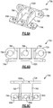
Figure 6A is a perspective view of another example bracket. -
Figure 6B is a front view of the bracket ofFigure 6A . -
Figure 6C is a top view of the bracket ofFigure 6A . -
Figure 1 schematically illustrates agas turbine engine 20. Thegas turbine engine 20 is disclosed herein as a two-spool turbofan that generally incorporates afan section 22, acompressor section 24, a combustor section 26 and aturbine section 28. Thefan section 22 drives air along a bypass flow path B in a bypass duct defined within ahousing 15, such as a fan case or nacelle, and also drives air along a core flow path C for compression and communication into the combustor section 26 then expansion through theturbine section 28. Although depicted as a two-spool turbofan gas turbine engine in the disclosed non-limiting embodiment, it should be understood that the concepts described herein are not limited to use with two-spool turbofans as the teachings may be applied to other types of turbine engines including but not limited to three-spool architectures. - The
exemplary engine 20 generally includes alow speed spool 30 and ahigh speed spool 32 mounted for rotation about an engine central longitudinal axis A relative to an enginestatic structure 36 viaseveral bearing systems 38. It should be understood that various bearingsystems 38 at various locations may alternatively or additionally be provided, and the location of bearingsystems 38 may be varied as appropriate to the application. - The
low speed spool 30 generally includes aninner shaft 40 that interconnects, a first (or low) pressure compressor 44 and a first (or low)pressure turbine 46. Theinner shaft 40 is connected to thefan 42 through a speed change mechanism, which in exemplarygas turbine engine 20 is illustrated as a gearedarchitecture 48 to drive afan 42 at a lower speed than thelow speed spool 30. Thehigh speed spool 32 includes anouter shaft 50 that interconnects a second (or high)pressure compressor 52 and a second (or high)pressure turbine 54. Acombustor 56 is arranged inexemplary gas turbine 20 between thehigh pressure compressor 52 and thehigh pressure turbine 54. Amid-turbine frame 57 of the enginestatic structure 36 may be arranged generally between thehigh pressure turbine 54 and thelow pressure turbine 46. Themid-turbine frame 57 furthersupports bearing systems 38 in theturbine section 28. Theinner shaft 40 and theouter shaft 50 are concentric and rotate via bearingsystems 38 about the engine central longitudinal axis A which is collinear with their longitudinal axes. - The core airflow is compressed by the low pressure compressor 44 then the
high pressure compressor 52, mixed and burned with fuel in thecombustor 56, then expanded over thehigh pressure turbine 54 andlow pressure turbine 46. Themid-turbine frame 57 includesairfoils 59 which are in the core airflow path C. Theturbines low speed spool 30 andhigh speed spool 32 in response to the expansion. It will be appreciated that each of the positions of thefan section 22,compressor section 24, combustor section 26,turbine section 28, and fandrive gear system 48 may be varied. For example,gear system 48 may be located aft of the low pressure compressor, or aft of the combustor section 26 or even aft ofturbine section 28, andfan 42 may be positioned forward or aft of the location ofgear system 48. - The
engine 20 in one example is a high-bypass geared aircraft engine. In a further example, theengine 20 bypass ratio is greater than about 6:1, with an example embodiment being greater than about 10:1, the gearedarchitecture 48 is an epicyclic gear train, such as a planetary gear system or other gear system, with a gear reduction ratio of greater than about 2.3:1 and thelow pressure turbine 46 has a pressure ratio that is greater than about 5:1. In one disclosed embodiment, theengine 20 bypass ratio is greater than about 10:1, the fan diameter is significantly larger than that of the low pressure compressor 44, and thelow pressure turbine 46 has a pressure ratio that is greater than about 5:1. Thelow pressure turbine 46 pressure ratio is pressure measured prior to the inlet oflow pressure turbine 46 as related to the pressure at the outlet of thelow pressure turbine 46 prior to an exhaust nozzle. The gearedarchitecture 48 may be an epicycle gear train, such as a planetary gear system or other gear system, with a gear reduction ratio of greater than about 2.3:1 and less than about 5:1. It should be understood, however, that the above parameters are only exemplary of one embodiment of a geared architecture engine and that the present invention is applicable to other gas turbine engines including but not limited to direct drive turbofans. - A significant amount of thrust is provided by the bypass flow B due to the high bypass ratio. The
fan section 22 of theengine 20 is designed for a particular flight condition -- typically cruise at about 0.8 Mach and about 35,000 feet (10,668 meters). The flight condition of 0.8 Mach and 35,000 ft (10,668 meters), with the engine at its best fuel consumption - also known as "bucket cruise Thrust Specific Fuel Consumption ('TSFC')" - is the industry standard parameter of lbm of fuel being burned divided by lbf of thrust the engine produces at that minimum point. "Low fan pressure ratio" is the pressure ratio across the fan blade alone, without a Fan Exit Guide Vane ("FEGV") system. The low fan pressure ratio as disclosed herein according to one non-limiting embodiment is less than about 1.45. "Low corrected fan tip speed" is the actual fan tip speed in ft/sec divided by an industry standard temperature correction of [(Tram °R) / (518.7 °R)]0.5 (where °R = K x 9/5). The "Low corrected fan tip speed" as disclosed herein according to one non-limiting embodiment is less than about 1150 ft / second (350.5 meters/second). -
Figure 2 illustrates an examplecomposite duct 60. Thecomposite duct 60 at least partially defines the bypass duct within thehousing 15 for transferring air along the bypass flow path B. Thecomposite duct 60 includes abody portion 62 extending in an axial direction and aflange 64 that extends radially outward located at an axial end of thebody portion 62. In this disclosure radial or radially and axial or axially are relative to the engine axis A unless described otherwise. Theflange 64 includes a plurality offlange bolt openings 66 located circumferentially around theflange 64. Theflange 64 could define a single continuous loop with thebody portion 62 or theflange 64 and thebody portion 62 could include multiple segments that are joined together to form a loop. Although theflange 64 is illustrated as being located on an axially downstream end of thebody portion 62, a similar flange could be located on an axially upstream end of thebody portion 62 and still benefit from this disclosure. - Because the
duct 60 is made of a composite, fibers from thebody portion 62 extend into theflange 64. In particular, theflange 64 is subject to bending moments during operation that subject the intersection of theflange 64 and thebody portion 62 to increased levels of stress. In order to address the increased level of stress at this intersection, a thickness of theflange 64 and the intersection of theflange 64 and thebody portion 62 is thicker than thebody portion 62 spaced axially inward from theflange 64. -
Figures 3 and 4 illustrate abracket 70 secured relative to thecomposite duct 60. Thebracket 70 includes afirst foot 72 connected to asecond foot 74 with aleg 76. Thefirst foot 72 includes a pair offlange fastener openings 78 that extend through thefirst foot 72 and are aligned with acorresponding flange fastener 80. Thesecond foot 74 is secured relative to thebody portion 62 of thecomposite duct 60 through a pair ofbody portion fasteners 82 extending through a corresponding pair of body portion fastener openings 84 (Figure 5 ). Thebody portion fasteners 82 can be secured to thebody portion 62 through a nut plate that has been riveted to a hole drilled through the body portion 62 (not shown). - In the illustrated example, the
first foot 72 is theflange 64 by two rows ofload spreaders 86 to spread loads from thefasteners 80 along a greater surface area of theflange 64. Thefasteners 80 connect theflange 64 on thecomposite duct 60 to aflange 94 extending from abody portion 92 of asecondary duct 90. The load spreaders 86 can include multiple segments that form a loop or a single segment that forms a loop in abutting contact with theflange 64. Although two rows ofload spreaders 86 are shown in the illustrated example, more or less than two rows ofload spreaders 86 could be used in this disclosure. This disclosure also applies to configurations that do not includesload spreaders 86. - Furthermore, in the illustrated example, the
flange 64 on thecomposite duct 60 is spaced from theflange 94 on thesecondary duct 90 by at least onespacer 96. The at least onespacer 96 can provide a structural transition between thecomposite duct 60 and thesecondary duct 90 and/or provide a neutral isolating material to prevent material reaction between theflange 64 and theflange 94. The at least onespacer 96 can also distribute loads along a surface of theflange 64 opposite theload spreaders 86. - As shown in
Figure 5 , theleg 76 on thebracket 70 is located between the pair offlange fastener openings 78 on thefirst foot 72 and theleg 76 is located between the pair of bodyportion fastener openings 84 on thesecond foot 74. Thefirst foot 72 also includes a ductflange support surface 100 opposite theleg 76 that can engage theload spreader 86 or theflange 64. Additionally, the ductflange support surface 100 is planar in the illustrated example such that the ductflange support surface 100 is flush against theload spreader 86 or theflange 64. - The
second foot 74 includes a bodyportion contact surface 102 opposite theleg 76 that directly contacts an outer surface of thebody portion 62 of thecomposite duct 60 as shown inFigures 3 and 4 . The bodyportion contact surface 102 includes a curvature that follows the profile of the outer surface of thebody portion 62. This allows thesecond foot 74 to sit flush against thebody portion 62 to increase load transfer area between thesecond foot 74 and thebody portion 62. -
Figures 6A-6B illustrate anotherexample bracket 70A that is similar to thebracket 70 except where described below or shown in the Figures. Thebracket 70A includes afirst foot 72A having at least threeflange fasteners openings 78A with adjacentflange fastener openings 78A separated bylegs 76A. Additionally, each of theflange fastener openings 78A are separated from an adjacent one of theflange fastener openings 78A by one of thelegs 76A. This allows thefirst foot 72A to be secured to more than two of theflange fasteners 80 to provide more support relative to theflange 64 on thecomposite duct 60. Additionally, because thefirst foot 72A is engaging more than twoflange fasteners 80, the flange fasteners opening 78A are arranged with a curvature to follow a curvature of theflange 64. However, a ductflange support surface 100A on thefirst foot 72A will remain planar even though an upper and lower edge of the ductflange support surface 100A may have a curvature that follows a curvature about axis A of theflange 64. - Similarly, the
bracket 70A includes asecond foot 74A having at least three bodyportion fastener openings 84A withadjacent fastener opening 84A separated by one of thelegs 76A. As described above, with respect to the bodyportion contact surface 102, a bodyportion contact surface 102A also follows an outer contour of thebody portion 62 of thecomposite duct 60. - Because the
flange 64 is integral with thebody portion 62 as described above, fibers from thebody portion 62 extend into theflange 64. During operation of thegas turbine engine 20 bending forces occur between theflange 64 and thebody portion 62 of thecomposite duct 60. This results in interlaminar stresses located at a transition between thebody portion 62 and theflange 64. One feature of this disclosure, is to reduce the interlaminar stresses at the transition between thebody portion 62 and theflange 64 as well as in other surrounding areas. In order to accomplish this feature, a plurality of thebracket composite duct 60 to engage thebody portion 62 and support theflange 64 to transfer and distribute loads from theflange 64 to thebody portion 62. - This transfer of forces diminishes or deflects bending moments applied to the
flange 64 to maintain the integrity of theflange 64 and increases the operating life of thecomposite duct 60. Another feature of using thebrackets composite duct 60 is that the number of fibers and thickness of theflange 64 and transition between theflange 64 and thebody portion 62 can be reduced which will improve the manufacturability of thecomposite duct 60 by reducing the complexity and thickness of the fiber layup. - The preceding description is exemplary rather than limiting in nature. Variations and modifications to the disclosed examples may become apparent to those skilled in the art that do not necessarily depart from the essence of this disclosure. The scope of legal protection given to this disclosure can only be determined by studying the following claims.
Claims (15)
- A bracket (70) assembly for a gas turbine engine (20) comprising:a first foot (72) including at least one flange fastener opening (78) and a duct flange support surface (100);a second foot (74) including at least one body portion fastener opening (84) and a duct body support surface (102); andat least one leg (76) connecting the first foot (72) relative to the second foot (74).
- The bracket (70) of claim 1, wherein the flange support surface (100) is planar; and/or the body portion support surface (102) includes a curvature.
- The bracket (70) of claims 1 or 2, wherein the duct flange support surface (100) is generally perpendicular to the duct body support surface (102).
- The assembly of any of claims 1 to 3, wherein the at least one flange fastener opening (78) includes of pair of flange fastener openings (78) and the at least one leg (76) is attached to the first foot (72) between the pair of flange fastener openings (78); and/or
the at least one body portion fastener opening (84) includes a pair of body portion fastener openings (84) and the at least one leg (76) is attached to the second foot (74) between the pair of body portion fastener openings (84). - The assembly of any of claims 1 to 4, wherein the first foot (72) is secured to a flange (64) on a composite duct (60) and the second foot (74) is secured to a body portion (62) of the composite duct (60).
- A gas turbine engine (20) comprising:a bypass duct at least partially defining a bypass flow path (B); anda composite duct assembly at least partially defining the bypass flow path (B), wherein the composite duct assembly includes:a composite duct (60) having a body portion (62) and a flange (64) extending radially outward from an end of the body portion (62); anda bracket (70) including a first foot (72) secured relative to the flange (64) and a second foot (74) secured relative to the body portion (62), wherein the first foot (72) includes at least one flange fastener opening (78) and the second foot (74) includes at least one body portion fastener opening (84).
- The gas turbine engine (20) of claim 6, wherein the first foot (72) includes a first mating surface (100) that is planar and the second foot (74) includes a duct body support surface (102) having a curvature following a curvature of the body portion (62) of the composite duct (60).
- The gas turbine engine (20) of claim 7, wherein the first mating surface (100) is generally perpendicular to the duct body support surface (102) and the bracket (70) includes at least one leg (76) connecting the first foot (72) to the second foot (74).
- The gas turbine engine (20) of claim 8, wherein the at least one leg (76) includes a plurality of legs (76A) connecting the first foot (72) and the second foot (74).
- The gas turbine engine (20) of claim 8, wherein the at least one flange fastener opening (78) includes of pair of flange fastener openings (78) and the at least one leg (76) is attached to the first foot (72) between the pair of flange fastener openings (78) and the at least one body portion (62) fastener opening (84) includes a pair of body portion (62) fastener openings (84) and the at least one leg (76) is attached to the second foot (74) between the pair of body portion fastener openings (84).
- The gas turbine engine (20) of claim 9, wherein the flange (64) includes a plurality of fastener openings (66) and the at least one flange fastener opening (78) is aligned with a corresponding one of the plurality of fastener openings (66) for accepting a flange fastener (80); and/or
including a fastener (82) extending through the at least one body portion fastener opening (84) in the second foot (74) and at least partially into the body portion (62). - The assembly of any of claims 1 to 5 or the gas turbine engine (20) of any of claims 6 to 11, further comprising at least one load spreader (86) separating the first foot (72) from the flange (64) and the flange (64) is integral with the body portion (62) and fibers from the body portion (62) extend into the flange (64).
- A method of supporting a flange (64) on a composite duct (60) comprising the steps of:securing a first foot (72) on a bracket (70) relative to a flange (64) on the composite duct (60); andsecuring a second foot (74) on the bracket (70) relative to a body portion (62) of the composite duct (60).
- The method of claim 13, further comprising aligning at least one flange fastener opening (78) in the first foot (72) with a flange fastener (80) extending through the flange (64) on the composite duct (60); and/or
comprising engaging the body portion (62) of the composite duct (60) with a fastener (82) extending through a duct fastener opening (84) in the second foot (74). - The method of claim 13 or 14, wherein the first foot (72) is connected to the second foot (74) with at least one leg (76) and the first foot (72) includes a duct flange support surface (100) and the second foot (74) includes a duct body support surface (102) that is generally perpendicular to the duct flange support surface (100) and includes a curvature that follows a profile of the body portion (62) of the composite duct (60).
Applications Claiming Priority (1)
| Application Number | Priority Date | Filing Date | Title |
|---|---|---|---|
| US16/459,985 US11073046B2 (en) | 2019-07-02 | 2019-07-02 | Gas turbine engine composite duct with bracket |
Publications (2)
| Publication Number | Publication Date |
|---|---|
| EP3760842A1 true EP3760842A1 (en) | 2021-01-06 |
| EP3760842B1 EP3760842B1 (en) | 2026-03-18 |
Family
ID=71452144
Family Applications (1)
| Application Number | Title | Priority Date | Filing Date |
|---|---|---|---|
| EP20183689.7A Active EP3760842B1 (en) | 2019-07-02 | 2020-07-02 | Gas turbine engine composite duct with bracket |
Country Status (2)
| Country | Link |
|---|---|
| US (1) | US11073046B2 (en) |
| EP (1) | EP3760842B1 (en) |
Families Citing this family (1)
| Publication number | Priority date | Publication date | Assignee | Title |
|---|---|---|---|---|
| FR3149868B1 (en) * | 2023-06-16 | 2025-06-20 | Airbus Operations Sas | DEVICE FOR COUPLING A PROPULSION SYSTEM TO A ENGINE PISTON OF AN AIRCRAFT AND CORRESPONDING AIRCRAFT |
Citations (4)
| Publication number | Priority date | Publication date | Assignee | Title |
|---|---|---|---|---|
| US20110168839A1 (en) * | 2008-09-23 | 2011-07-14 | Airbus Operations Sas | Device for connecting an air inlet with an aircraft nacelle actuator assembly |
| US20140075957A1 (en) * | 2012-09-20 | 2014-03-20 | United Technologies Corporation | Formed gussets for brackets on gas turbine engines |
| US20160169046A1 (en) * | 2014-12-10 | 2016-06-16 | Rolls-Royce Corporation | Stiffening rib |
| US20170191448A1 (en) * | 2015-12-30 | 2017-07-06 | General Electric Company | Method and system for improving structural characteristics of composite component corners |
Family Cites Families (4)
| Publication number | Priority date | Publication date | Assignee | Title |
|---|---|---|---|---|
| US1433324A (en) * | 1922-10-24 | Cak book | ||
| US20030218110A1 (en) * | 2002-05-23 | 2003-11-27 | Burgess Andrew Paul | Deck mounting bracket |
| US8079773B2 (en) | 2005-10-18 | 2011-12-20 | General Electric Company | Methods and apparatus for assembling composite structures |
| US8206102B2 (en) | 2007-08-16 | 2012-06-26 | United Technologies Corporation | Attachment interface for a gas turbine engine composite duct structure |
-
2019
- 2019-07-02 US US16/459,985 patent/US11073046B2/en active Active
-
2020
- 2020-07-02 EP EP20183689.7A patent/EP3760842B1/en active Active
Patent Citations (4)
| Publication number | Priority date | Publication date | Assignee | Title |
|---|---|---|---|---|
| US20110168839A1 (en) * | 2008-09-23 | 2011-07-14 | Airbus Operations Sas | Device for connecting an air inlet with an aircraft nacelle actuator assembly |
| US20140075957A1 (en) * | 2012-09-20 | 2014-03-20 | United Technologies Corporation | Formed gussets for brackets on gas turbine engines |
| US20160169046A1 (en) * | 2014-12-10 | 2016-06-16 | Rolls-Royce Corporation | Stiffening rib |
| US20170191448A1 (en) * | 2015-12-30 | 2017-07-06 | General Electric Company | Method and system for improving structural characteristics of composite component corners |
Also Published As
| Publication number | Publication date |
|---|---|
| US11073046B2 (en) | 2021-07-27 |
| EP3760842B1 (en) | 2026-03-18 |
| US20210003037A1 (en) | 2021-01-07 |
Similar Documents
| Publication | Publication Date | Title |
|---|---|---|
| EP3892824B1 (en) | Pin attachment for cmc components in a gas turbine engine | |
| US9982600B2 (en) | Pre-skewed capture plate | |
| US11421558B2 (en) | Gas turbine engine component | |
| US10533437B2 (en) | Inner diffuser case for a gas turbine engine | |
| US11512604B1 (en) | Spring for radially stacked assemblies | |
| WO2014022119A1 (en) | Retrofitable auxiliary inlet scoop | |
| US10060390B2 (en) | Bypass duct with angled drag links | |
| EP3708773B1 (en) | Gas turbine engine comprising a seal for a rotor stack and corresponding method of sealing a shaft relatively to a rotor disk | |
| US10655502B2 (en) | Stator assembly with retention clip for gas turbine engine | |
| US10533456B2 (en) | Stator assembly with contoured retention clip for gas turbine engine | |
| EP3760842A1 (en) | Gas turbine engine composite duct with bracket | |
| EP3282101B1 (en) | Shim for gas turbine engine | |
| EP3564495B1 (en) | Gas turbine engine exhaust component | |
| US9874111B2 (en) | Low thermal mass joint | |
| EP4071409B1 (en) | Gas turbine engine with cmc combustor panel | |
| EP3760843B1 (en) | Duct assembly for a gas turbine engine |
Legal Events
| Date | Code | Title | Description |
|---|---|---|---|
| PUAI | Public reference made under article 153(3) epc to a published international application that has entered the european phase |
Free format text: ORIGINAL CODE: 0009012 |
|
| STAA | Information on the status of an ep patent application or granted ep patent |
Free format text: STATUS: THE APPLICATION HAS BEEN PUBLISHED |
|
| AK | Designated contracting states |
Kind code of ref document: A1 Designated state(s): AL AT BE BG CH CY CZ DE DK EE ES FI FR GB GR HR HU IE IS IT LI LT LU LV MC MK MT NL NO PL PT RO RS SE SI SK SM TR |
|
| AX | Request for extension of the european patent |
Extension state: BA ME |
|
| STAA | Information on the status of an ep patent application or granted ep patent |
Free format text: STATUS: REQUEST FOR EXAMINATION WAS MADE |
|
| 17P | Request for examination filed |
Effective date: 20210706 |
|
| RBV | Designated contracting states (corrected) |
Designated state(s): AL AT BE BG CH CY CZ DE DK EE ES FI FR GB GR HR HU IE IS IT LI LT LU LV MC MK MT NL NO PL PT RO RS SE SI SK SM TR |
|
| STAA | Information on the status of an ep patent application or granted ep patent |
Free format text: STATUS: EXAMINATION IS IN PROGRESS |
|
| 17Q | First examination report despatched |
Effective date: 20221129 |
|
| RAP3 | Party data changed (applicant data changed or rights of an application transferred) |
Owner name: RTX CORPORATION |
|
| GRAP | Despatch of communication of intention to grant a patent |
Free format text: ORIGINAL CODE: EPIDOSNIGR1 |
|
| STAA | Information on the status of an ep patent application or granted ep patent |
Free format text: STATUS: GRANT OF PATENT IS INTENDED |
|
| INTG | Intention to grant announced |
Effective date: 20251017 |
|
| GRAS | Grant fee paid |
Free format text: ORIGINAL CODE: EPIDOSNIGR3 |
|
| GRAA | (expected) grant |
Free format text: ORIGINAL CODE: 0009210 |
|
| STAA | Information on the status of an ep patent application or granted ep patent |
Free format text: STATUS: THE PATENT HAS BEEN GRANTED |
|
| AK | Designated contracting states |
Kind code of ref document: B1 Designated state(s): AL AT BE BG CH CY CZ DE DK EE ES FI FR GB GR HR HU IE IS IT LI LT LU LV MC MK MT NL NO PL PT RO RS SE SI SK SM TR |
|
| REG | Reference to a national code |
Ref country code: CH Ref legal event code: F10 Free format text: ST27 STATUS EVENT CODE: U-0-0-F10-F00 (AS PROVIDED BY THE NATIONAL OFFICE) Effective date: 20260318 Ref country code: GB Ref legal event code: FG4D |
|
| REG | Reference to a national code |
Ref country code: DE Ref legal event code: R096 Ref document number: 602020068711 Country of ref document: DE |
|
| REG | Reference to a national code |
Ref country code: IE Ref legal event code: FG4D |