EP3760567A1 - Crane - Google Patents
Crane Download PDFInfo
- Publication number
- EP3760567A1 EP3760567A1 EP19760219.6A EP19760219A EP3760567A1 EP 3760567 A1 EP3760567 A1 EP 3760567A1 EP 19760219 A EP19760219 A EP 19760219A EP 3760567 A1 EP3760567 A1 EP 3760567A1
- Authority
- EP
- European Patent Office
- Prior art keywords
- control signal
- actuator
- unit
- boom
- basis
- Prior art date
- Legal status (The legal status is an assumption and is not a legal conclusion. Google has not performed a legal analysis and makes no representation as to the accuracy of the status listed.)
- Pending
Links
Images





Classifications
-
- B—PERFORMING OPERATIONS; TRANSPORTING
- B66—HOISTING; LIFTING; HAULING
- B66C—CRANES; LOAD-ENGAGING ELEMENTS OR DEVICES FOR CRANES, CAPSTANS, WINCHES, OR TACKLES
- B66C13/00—Other constructional features or details
- B66C13/18—Control systems or devices
-
- B—PERFORMING OPERATIONS; TRANSPORTING
- B66—HOISTING; LIFTING; HAULING
- B66C—CRANES; LOAD-ENGAGING ELEMENTS OR DEVICES FOR CRANES, CAPSTANS, WINCHES, OR TACKLES
- B66C13/00—Other constructional features or details
- B66C13/04—Auxiliary devices for controlling movements of suspended loads, or preventing cable slack
- B66C13/06—Auxiliary devices for controlling movements of suspended loads, or preventing cable slack for minimising or preventing longitudinal or transverse swinging of loads
- B66C13/063—Auxiliary devices for controlling movements of suspended loads, or preventing cable slack for minimising or preventing longitudinal or transverse swinging of loads electrical
-
- B—PERFORMING OPERATIONS; TRANSPORTING
- B66—HOISTING; LIFTING; HAULING
- B66C—CRANES; LOAD-ENGAGING ELEMENTS OR DEVICES FOR CRANES, CAPSTANS, WINCHES, OR TACKLES
- B66C13/00—Other constructional features or details
- B66C13/18—Control systems or devices
- B66C13/22—Control systems or devices for electric drives
-
- B—PERFORMING OPERATIONS; TRANSPORTING
- B66—HOISTING; LIFTING; HAULING
- B66C—CRANES; LOAD-ENGAGING ELEMENTS OR DEVICES FOR CRANES, CAPSTANS, WINCHES, OR TACKLES
- B66C2700/00—Cranes
- B66C2700/08—Electrical assemblies or electrical control devices for cranes, winches, capstans or electrical hoists
- B66C2700/085—Control actuators
Definitions
- the present invention relates to a crane.
- a crane has been known as a typical work vehicle.
- the crane is mainly composed of a traveling body and a turning body.
- the traveling body includes a plurality of wheels, and is configured to travel freely.
- the turning body includes a boom, a wire rope, a hook, and the like.
- Such a turning body is configured to be able to carry load.
- such a crane is provided with an actuator for carrying a load and a control device for instructing an operating state of the actuator.
- the filtering control signal means a signal obtained by applying a filter having a predetermined characteristic to a basic control signal of the actuator.
- the filter may be a notch filter.
- the notch filter has a characteristic that the attenuation rate increases as it approaches the resonance frequency in an arbitrary range centered on the resonance frequency. The resonance frequency is calculated on the basis of the suspension length of the hook.
- the above-mentioned actuator is a turning hydraulic motor and the turning operation of the boom is manually stopped.
- the turning operation of the boom is not immediately stopped, but the deceleration section on the basis of the filtering control signal is provided to suppress the swing of the load.
- such a characteristic means that the turning operation of the boom does not match the operation by the operator, and there is a problem that the more experienced the operator, the greater the discomfort. Therefore, there is a demand for a crane that can select an operation characteristic with respect to a control mode of a load transport operation.
- Patent Literature 1 JP 2015-151211 A
- An object of the invention is to provide a crane capable of selecting an operation characteristic with respect to a control mode of a load transport operation.
- An aspect of a crane according to the invention includes a operable functional unit, an operation unit that receives an operation input for operating the operable functional unit, an actuator that drives the operable functional unit, a first generation unit that generates a first control signal for the actuator on the basis of the operation input, a switch unit that can be switched between a first state and a second state, a first filter unit that filters the first control signal to generate a second control signal when the switch unit is in the second state, and a control unit that controls the actuator on the basis of the first control signal when the switch unit is in the first state, and controls the actuator on the basis of the second control signal when the switch unit is in the second state.
- the crane 1 is mainly composed of a traveling body 2 and a turning body 3.
- the traveling body 2 includes a pair of left and right front tires 4 and rear tires 5.
- the traveling body 2 is provided with an outrigger 6 which is grounded and stabilized when carrying the load W.
- the turning body 3 is supported on the upper part of the traveling body 2. Such a turning body 3 can be freely turned by an actuator.
- the turning body 3 is provided with a boom 7 so as to project forward from the rear part thereof. Therefore, the boom 7 can be freely turned by an actuator (see arrow A). Further, the boom 7 can be freely extended and contracted by an actuator (see arrow B).
- the boom 7 can be freely raised and lowered by an actuator (see arrow C).
- a wire rope 8 is stretched over the boom 7.
- a winch 9 around which the wire rope 8 is wound is disposed on the base end side of the boom 7, and a hook 10 is suspended by the wire rope 8 on the tip end side of the boom 7.
- the winch 9 is configured integrally with the actuator, and allows the wire rope 8 to be wound and unwound. Therefore, the hook 10 can be freely raised and lowered by the actuator (see arrow D).
- the turning body 3 is provided with a cabin 11 on the side of the boom 7.
- the winch 9 corresponds to an example of a operable functional unit.
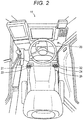
- a turning operation tool 21, a telescopic operation tool 22, a derricking operation tool 23, and a winding operation tool 24, which will be described later, are provided inside the cabin 11. Further, the cabin 11 is provided with a changeover switch 25. Each of these operation units 21 to 24 corresponds to an example of the operation unit.
- the operation unit receives an operation input for operating the operable functional unit.
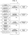
- control system will be described with reference to Fig. 3 .
- present control system is an example of a conceivable configuration and is not limited to this.
- the control system is mainly configured by a control device 20.
- Various operation tools 21 to 24 are connected to the control device 20.
- the control device 20 is connected with a turning valve 31, a telescopic valve 32, a derricking valve 33, and a winding valve 34.
- control device 20 is connected to a weight sensor 40, a turning sensor 41, an extension/contraction sensor 42, a derricking sensor 43, and a winding sensor 44.
- the weight sensor 40 can detect the weight of the load W. Therefore, the control device 20 can recognize the weight of the load W.
- a turning hydraulic motor 51 corresponds to an example of the actuator.
- the turning hydraulic motor 51 is appropriately operated by the turning valve 31 which is an electromagnetic proportional switching valve.
- the turning hydraulic motor 51 is appropriately operated by the turning valve 31 switching the flow direction of the hydraulic oil or adjusting the flow rate of the hydraulic oil. Further, the turning angle and the turning speed of the boom 7 are detected by the turning sensor 41. Therefore, the control device 20 can recognize the turning angle and the turning speed of the boom 7.
- a telescopic hydraulic cylinder 52 corresponds to an example of the actuator.
- the telescopic hydraulic cylinder 52 is appropriately operated by the telescopic valve 32 which is an electromagnetic proportional switching valve.
- the telescopic hydraulic cylinder 52 is appropriately operated by the telescopic valve 32 switching the flow direction of the hydraulic oil or adjusting the flow rate of the hydraulic oil.
- the extension/contraction length and extension/contraction speed of the boom 7 are detected by the extension/contraction sensor 42. Therefore, the control device 20 can recognize the extension/contraction length and the extension/contraction speed of the boom 7.
- a derricking hydraulic cylinder 53 corresponds to an example of the actuator.
- the derricking hydraulic cylinder 53 is appropriately operated by the derricking valve 33 which is an electromagnetic proportional switching valve.
- the derricking hydraulic cylinder 53 is appropriately operated by the derricking valve 33 switching the flow direction of the hydraulic oil or adjusting the flow rate of the hydraulic oil.
- the derricking angle and derricking speed of the boom 7 are detected by the derricking sensor 43. Therefore, the control device 20 can recognize the derricking angle and derricking speed of the boom 7.
- a winding hydraulic motor 54 corresponds to an example of the actuator.
- the winding hydraulic motor 54 is appropriately operated by the winding valve 34 which is an electromagnetic proportional switching valve.
- the winding hydraulic motor 54 is appropriately operated by the winding valve 34 switching the flow direction of the hydraulic oil or adjusting the flow rate of the hydraulic oil.
- the suspension length L (see Fig. 1 ) and the lifting speed of the hook 10 are detected by the winding sensor 44. Therefore, the control device 20 can recognize the suspension length L and the lifting speed of the hook 10.
- the control device 20 controls each actuator (51, 52, 53, 54) via various valves 31 to 34.
- the control device 20 includes a basic control signal creation unit 20a, a resonance frequency calculation unit 20b, a filter coefficient calculation unit 20c, and a filtering control signal creation unit 20d.
- the filtering control signal creation unit 20d may be regarded as an example of the first filter unit and the second filter unit.
- the first filter unit filters the first control signal to generate a second control signal.
- the second filter unit filters the third control signal to generate a fourth control signal.
- the first filter unit and the second filter unit may have different filter characteristics. That is, the filter coefficient of the first filter unit and the filter coefficient of the second filter unit may be different.
- the first filter unit and the second filter unit may have the same filter characteristics.
- the basic control signal creation unit 20a creates a basic control signal S that is a speed command for each actuator (51, 52, 53, 54) (see Fig. 5 ).
- the basic control signal creation unit 20a recognizes the operation amount and the operation speed of the various operation tools 21 to 24 by the operator, and creates the basic control signal S for each situation.
- the basic control signal creation unit 20a creates a basic control signal S according to the operation amount and the operation speed of the turning operation tool 21, a basic control signal S according to the operation amount and the operation speed of the telescopic operation tool 22, a basic control signal S according to the operation amount and operation speed of the derricking operation tool 23, and/or a basic control signal S according to the operation amount and operation speed of the winding operation tool 24.
- the basic control signal creation unit 20a corresponds to an example of the first generation unit.
- the resonance frequency calculation unit 20b calculates a resonance frequency ⁇ which is a swing frequency of the load W caused by the operation of each actuator (51, 52, 53, 54).
- the resonance frequency calculation unit 20b recognizes the suspension length L of the hook 10 on the basis of the posture of the boom 7 and the unwinding amount of the wire rope 8, and calculates the resonance frequency ⁇ for each situation.
- the filter coefficient calculation unit 20c calculates a center frequency coefficient ⁇ n, a notch width coefficient ⁇ , and a notch depth coefficient ⁇ of a transfer coefficient H(s) included in the notch filter F described later.
- the filter coefficient calculation unit 20c calculates the corresponding center frequency coefficient ⁇ n with the resonance frequency ⁇ calculated by the resonance frequency calculation unit 20b as a center.
- the filter coefficient calculation unit 20c calculates the notch width coefficient ⁇ and the notch depth coefficient ⁇ corresponding to each basic control signal S.
- the transfer coefficient H(s) is represented by the following expression using the center frequency coefficient ⁇ n, the notch width coefficient ⁇ , and the notch depth coefficient ⁇ .
- the transfer coefficient H(s) is also called a filter characteristic. If the parameters of the transfer coefficient H(s) are different, it may be considered that the filter characteristics of the notch filter F are different.
- H s s 2 + 2 ⁇ n s + ⁇ n 2 s 2 + 2 ⁇ n s + ⁇ n 2
- the filtering control signal creation unit 20d creates the notch filter F, and also applies the notch filter F to the basic control signal S to create a filtering control signal Sf (see Fig. 5 ).
- the filtering control signal creation unit 20d creates the notch filter F by acquiring the various coefficients ⁇ n, ⁇ , and ⁇ from the filter coefficient calculation unit 20c.
- the filtering control signal creation unit 20d acquires the basic control signal S from the basic control signal creation unit 20a, applies the notch filter F to the basic control signal S, and creates the filtering control signal Sf.
- the filtering control signal creation unit 20d creates the filtering control signal Sf from the basic control signal S and the notch filter F according to the operation amount of the turning operation tool 21 and the like. Further, the filtering control signal creation unit 20d creates the filtering control signal Sf on the basis of the basic control signal S and the notch filter F according to the operation amount of the telescopic operation tool 22 and the like. The filtering control signal creation unit 20d creates the filtering control signal Sf on the basis of the basic control signal S and the notch filter F corresponding to the operation amount of the derricking operation tool 23 and the like. Further, the filtering control signal creation unit 20d generates the filtering control signal Sf on the basis of the basic control signal S and the notch filter F according to the operation amount of the winding operation tool 24 and the like.
- control device 20 controls the various valves 31 to 34 on the basis of the filtering control signal Sf.
- control device 20 controls each actuator (51, 52, 53, 54) on the basis of the filtering control signal Sf.
- the notch filter F has a characteristic that the attenuation rate increases as it approaches the resonance frequency ⁇ in an arbitrary range centered on the resonance frequency ⁇ .
- An arbitrary range centered on the resonance frequency ⁇ is represented as a notch width Bn.
- the difference of the attenuation amount in the notch width Bn is represented as a notch depth Dn.
- the notch filter F is specified by the resonance frequency ⁇ , the notch width Bn, and the notch depth Dn.
- the filtering control signal Sf is a speed command transmitted to each actuator (51, 52, 53, 54).
- the filtering control signal Sf corresponding to the acceleration of the boom 7 or the like has a characteristic that the acceleration is gentler than the basic control signal S, and temporarily causes deceleration and then causes acceleration again (see part X in Fig. 5 ).
- the reason for temporarily decelerating is to suppress the swing of the load W during acceleration.
- the filtering control signal Sf corresponding to deceleration of the boom 7 or the like has a characteristic that the deceleration is gentler or similar to that of the basic control signal S, and temporarily causes acceleration and then causes deceleration again (See part Y in Fig. 5 ).
- the reason for temporarily accelerating is to suppress the swing of the load W during deceleration.
- the transport allowable region Rp represents a region where the transport of the load W is permitted.
- the boom 7 is also allowed to move.
- the notch depth coefficient ⁇ is selectable within the range of 0 to 1.
- notch depth coefficient ⁇ When the notch depth coefficient ⁇ is 0 or a numerical value close to 0, a slow reaction to the operation of the operator occurs, and the swing of the load W can be suppressed. On the other hand, when the notch depth coefficient ⁇ is 1 or a numerical value close to 1, an agile reaction to the operation of the operator occurs, and it becomes possible to match the operation feeling of the operator.
- the transport restricted region Rr represents a region where transport of the load W is not permitted.
- the boom 7 is not allowed to move (enter).
- the notch depth coefficient ⁇ and the like cannot be determined.
- the transport restricted region Rr is provided so as to surround an obstacle B and the like. Therefore, it is possible to prevent the load W and the boom 7 from colliding with the obstacle B or the like. In addition, when the load W or the boom 7 in the transport allowable region Rp is moving toward the transport restricted region Rr, the transport operation is automatically stopped.
- the boom 7 corresponds to an example of the operable functional unit.
- step S11 the control device 20 determines whether the automatic stop signal has been input.
- the automatic stop signal is created when the load W or the boom 7 approaches the transport restricted region Rr.
- the control process proceeds to step S12, and when the automatic stop signal is not input (“NO” in step S11), the control process proceeds to step S14.
- step S12 the control device 20 creates an automatic control signal Sa for the turning hydraulic motor 51 (see Fig. 8 ).
- the automatic control signal Sa is the basic control signal S created at the time of automatic stop.
- the automatic control signal Sa corresponds to an example of the third control signal.
- the automatic control signal Sa is created on the basis of the turning speed of the boom 7, the weight of the load W, and the like.
- the automatic control signal Sa is created on the basis of the program used at the time of automatic stop.
- the program is stored in the control device 20 in advance.
- the part that generates the automatic control signal Sa may be regarded as an example of a second generation unit.
- step S13 the control device 20 creates a filtering control signal Sf (hereinafter referred to as "automatic filtering control signal Sfa”) by applying the notch filter F to the automatic control signal Sa (third control signal) (see Fig. 8 ).
- the notch filter F at this time is created on the basis of the notch depth coefficient ⁇ that is arbitrarily set.
- the automatic filtering control signal Sfa corresponds to an example of the fourth control signal.
- the control device 20 controls the turning hydraulic motor 51 on the basis of the automatic filtering control signal Sfa.
- the control content that gives priority to suppressing the swing of the load W.
- the load W starts to swing due to inertia (see (A) in Fig. 8 ).
- the turning speed of the boom 7 is temporarily increased to catch up with the boom 7 and suppress the swing of the load W (see (B) in Fig. 8 ). Thereafter, the turning speed is decelerated again while the swing of the load W is suppressed (see (C) in Fig. 8 ). Further, the notch depth coefficient ⁇ of the notch filter F is freely changed by an adjustment dial 26 described later.
- the flow rate of the load W and the boom 7 (the moving distance from when the turning operation is stopped until the turning operation is stopped) is determined to be within an allowable flow rate Pd.
- the operator can arbitrarily set the allowable flow rate Pd.
- step S14 the control device 20 determines whether a manual stop signal is input.
- the manual stop signal is created when the operator operates the turning operation tool 21 to stop the turning operation of the boom 7.
- the control process proceeds to step S15, and when the manual stop signal is not input (“NO” in step S14), the control process returns to step S11.
- step S15 the control device 20 creates a manual control signal Sm for the turning hydraulic motor 51 (see Fig. 9 ).
- the manual control signal Sm indicates the basic control signal S created at the time of manual stop.
- the manual control signal Sm is created on the basis of the operation amount and the operation speed of the turning operation tool 21 by the operator.
- the manual control signal Sm is created on the basis of a program used when manually stopping.
- the program is stored in the control device 20 in advance.
- step S16 the control device 20 determines whether the changeover switch 25 is "ON” or "OFF".
- the changeover switch 25 can be freely changed by the operator.
- the control process proceeds to step S17, and when the changeover switch 25 is "OFF” ("NO" in step S16), the control process proceeds to step S18.
- the state in which the changeover switch 25 is "OFF” is defined as the first state of the changeover switch 25.
- the state in which the changeover switch 25 is "ON” is defined as the second state of the changeover switch 25.
- the changeover switch 25 corresponds to an example of a switch unit.
- step S17 the control device 20 applies the notch filter F to the manual control signal Sm to create the filtering control signal Sf (hereinafter, referred to as "manual filtering control signal Sfm”) (see Fig. 9 ).
- the notch filter F at this time is also created on the basis of the notch depth coefficient ⁇ that is arbitrarily set.
- the notch filter F used in step S13 and the notch filter F used in step S17 may be the same filter or different filters.
- the ratio of frequency components attenuated from the manual control signal Sm may be smaller than the ratio of frequency components attenuated from the automatic control signal Sa by the notch filter F used in step S13.
- the ratio of frequency components attenuated from the manual control signal Sm when the actuator is controlled by manual control may be smaller than the ratio of frequency components attenuated from the automatic control signal Sa when the actuator is controlled by automatic control (the case of step S13).
- control device 20 controls the turning hydraulic motor 51 on the basis of the manual filtering control signal Sfm.
- the control content that gives priority to matching with the operation feeling of the operator rather than suppressing the swing of the load W, for example.
- the notch depth coefficient ⁇ of the notch filter F is freely changed by an adjustment dial 27 described later.
- the swing amount of the load W is determined to be within an allowable swing width Px. The operator can arbitrarily set the allowable swing width Px.
- step S18 the control device 20 controls the turning hydraulic motor 51 on the basis of the manual control signal Sm. That is, the control device 20 controls the turning hydraulic motor 51 on the basis of the manual control signal Sm as it is, without creating the manual filtering control signal Sfm.
- the crane 1 is provided with the actuator (the turning hydraulic motor 51) used for carrying the load W, the control device 20 for instructing the operating state of the actuator 51, and a switch (the changeover switch 25) which is connected to the control device 20 to switch the control mode of the actuator 51.
- the actuator the turning hydraulic motor 51
- the control device 20 for instructing the operating state of the actuator 51
- a switch the changeover switch 25
- the control device 20 controls the actuator 51 on the basis of the basic control signal S (manual control signal Sm) of the actuator 51 to stop the transport operation.
- the control device 20 applies the notch filter F to the basic control signal Sm of the actuator 51 to create the filtering control signal Sf (manual filtering control signal Sfm). Then, the control device 20 controls the actuator 51 on the basis of the created filtering control signal Sfm to stop the transport operation.
- the operation characteristics can be selected for the control mode when the transport operation of the load W is stopped.
- the actuator (the turning hydraulic motor 51) is a hydraulic motor that turns the boom 7.
- the control device 20 controls the hydraulic motor 51 on the basis of the basic control signal S (manual control signal Sm) of the hydraulic motor 51 to stop the turning operation.
- the control device 20 applies the notch filter F to the basic control signal Sm of the hydraulic motor 51 to create the filtering control signal Sf (manual filtering control signal Sfm). Then, the control device 20 controls the hydraulic motor 51 on the basis of the created filtering control signal Sfm to stop the turning operation. According to such a crane 1, the operation characteristics can be selected for the control mode when the turning operation of the boom 7 is stopped.
- the swing frequency of the load W is set to the resonance frequency ⁇ in order to suppress the swing of the load W caused by the turning operation of the boom 7.
- the swing frequency of the boom 7 may be set to the resonance frequency ⁇ .
- the resonance frequency ⁇ may be set in consideration of both the swing frequency of the load W and the swing frequency of the boom 7.
- the operator operates the changeover switch 25 to select the control mode, but the invention is not limited thereto.
- the changeover switch 25 may be incorporated in an arithmetic device of the control device 20 and may be configured in advance so as to select a desired control mode.
- the configuration may be such that an appropriate control mode is automatically selected according to the situation. That is, the changeover switch 25 is not limited to being manually operated.
- the load W is moving toward the transport restricted region Rr due to the telescopic operation of the boom 7
- the description will be given with reference to Figs. 10 and 11 together with Fig. 7 .
- the telescopic operation of the boom 7 is described as an extension operation, the same applies to a contraction operation.
- the boom 7 corresponds to an example of the operable unctional unit.
- step S11 the control device 20 determines whether the automatic stop signal has been input.
- the automatic stop signal is created when the load W or the boom 7 approaches the transport restricted region Rr.
- the control process proceeds to step S12, and when the automatic stop signal is not input (“NO” in step S11), the control process proceeds to step S14.
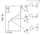
- step S12 the control device 20 creates the automatic control signal Sa for the telescopic hydraulic cylinder 52 (see Fig. 10 ).
- the automatic control signal Sa is the basic control signal S created at the time of automatic stop.
- the automatic control signal Sa is created on the basis of the extension speed of the boom 7, the weight of the load W, and the like.
- the automatic control signal Sa is created on the basis of the program used at the time of automatic stop.
- the program is stored in the control device 20 in advance.
- step S13 the control device 20 applies the notch filter F to the automatic control signal Sa to create the filtering control signal Sf (hereinafter, referred to as "automatic filtering control signal Sfa") (see Fig. 10 ).
- the notch filter F at this time is created on the basis of the notch depth coefficient ⁇ that is arbitrarily set.
- control device 20 controls the telescopic hydraulic cylinder 52 on the basis of the automatic filtering control signal Sfa.
- the control content that gives priority to suppressing the swing of the load W.
- the load W starts to swing due to inertia (see (A) in Fig. 10 ) .
- the extension speed of the boom 7 is temporarily increased to catch up with the boom 7 and suppress the swing of the load W (see (B) in Fig. 10 ). Thereafter, the load W is decelerated again while the swing is suppressed (see (C) in Fig. 10 ).
- the notch depth coefficient ⁇ of the notch filter F is freely changed by the adjustment dial 26 described later.
- the flow rate of the load W and the boom 7 (the moving distance from when the turning operation is stopped until the extension operation is stopped) is determined to be within an allowable flow rate Pd. The operator can arbitrarily set the allowable flow rate Pd.
- step S14 the control device 20 determines whether the manual stop signal is input.
- the manual stop signal is created when the operator operates the telescopic operation tool 22 to stop the extension operation of the boom 7.
- the control process proceeds to step S15, and when the manual stop signal is not input (“NO” in step S14), the control process returns to step S11.
- step S15 the control device 20 creates the manual control signal Sm for the telescopic hydraulic cylinder 52 (see Fig. 11 ).
- the manual control signal Sm is the basic control signal S created at the time of manual stop.
- the manual control signal Sm is created on the basis of the operation amount and the operation speed of the telescopic operation tool 22 by the operator.
- the manual control signal Sm is created on the basis of a program used when manually stopping.
- the program is stored in the control device 20 in advance.
- step S16 the control device 20 determines whether the changeover switch 25 is "ON” or "OFF".
- the changeover switch 25 can be freely changed by the operator.
- the control process proceeds to step S17, and when the changeover switch 25 is "OFF” ("NO" in step S16), the control process proceeds to step S18.
- step S17 the control device 20 applies the notch filter F to the manual control signal Sm to create the filtering control signal Sf (hereinafter referred to as "manual filtering control signal Sfm") (see Fig. 11 ).
- the notch filter F at this time is also created on the basis of the notch depth coefficient ⁇ that is arbitrarily set.
- control device 20 controls the telescopic hydraulic cylinder 52 on the basis of the manual filtering control signal Sfm.
- the control content that gives priority to matching with the operation feeling of the operator rather than suppressing the swing of the load W, for example.
- the notch depth coefficient ⁇ of the notch filter F is freely changed by the adjustment dial 27 described later.
- the swing amount of the load W is determined to be within the allowable swing width Px. The operator can arbitrarily set the allowable swing width Px.
- step S18 the control device 20 controls the telescopic hydraulic cylinder 52 on the basis of the manual control signal Sm. That is, the control device 20 controls the telescopic hydraulic cylinder 52 on the basis of the manual control signal Sm as it is, without creating the manual filtering control signal Sfm. As a result, it is possible to realize the control content that gives the highest priority to matching the operation feeling of the operator without considering the swing of the load W.
- the crane 1 is provided with the actuator (the telescopic hydraulic cylinder 52) used for carrying the load W, the control device 20 for instructing the operating state of the actuator 52, and a switch (the changeover switch 25) which is connected to the control device 20 to switch the control mode of the actuator 52.
- the actuator the telescopic hydraulic cylinder 52
- the control device 20 for instructing the operating state of the actuator 52
- a switch the changeover switch 25
- the control device 20 controls the actuator 52 on the basis of the basic control signal S (manual control signal Sm) of the actuator 52 to stop the transport operation.
- the control device 20 applies the notch filter F to the basic control signal Sm of the actuator 52 to create the filtering control signal Sf (manual filtering control signal Sfm), and controls the actuator 52 on the basis of the filtering control signal Sfm to stop the transport operation.
- the operation characteristics can be selected for the control mode when the transport operation of the load W is stopped.
- the actuator (the telescopic hydraulic cylinder 52) is a hydraulic cylinder that expands and contracts the boom 7.
- the control device 20 controls the hydraulic cylinder 52 on the basis of the basic control signal S (manual control signal Sm) of the hydraulic cylinder 52 to stop the telescopic operation.
- the control device 20 applies the notch filter F to the basic control signal Sm of the hydraulic cylinder 52 to create the filtering control signal Sf (manual filtering control signal Sfm), and controls the hydraulic cylinder 52 on the basis of the filtering control signal Sfm to stop the telescopic operation.
- the operation characteristics can be selected for the control mode when the telescopic operation of the boom 7 is stopped.
- the swing frequency of the load W is set to the resonance frequency ⁇ in order to suppress the swing of the load W caused by the telescopic operation of the boom 7.
- the swing frequency of the boom 7 may be set to the resonance frequency ⁇ .
- the resonance frequency ⁇ may be set in consideration of both the swing frequency of the load W and the swing frequency of the boom 7.
- the operator operates the changeover switch 25 to select the control mode, but the invention is not limited thereto.
- the changeover switch 25 may be incorporated in the arithmetic device of the control device 20 and may be configured in advance so as to select a desired control mode.
- the configuration may be such that an appropriate control mode is automatically selected according to the situation. That is, the changeover switch 25 is not limited to being manually operated.
- step S11 the control device 20 determines whether the automatic stop signal has been input.
- the automatic stop signal is created when the load W or the boom 7 approaches the transport restricted region Rr.
- the control process proceeds to step S12, and when the automatic stop signal is not input (“NO” in step S11), the control process proceeds to step S14.
- step S12 the control device 20 creates the automatic control signal Sa for the derricking hydraulic cylinder 53 (see Fig. 12 ).
- the automatic control signal Sa is the basic control signal S created at the time of automatic stop.
- the automatic control signal Sa is created on the basis of the rising speed of the boom 7, the weight of the load W, and the like.
- the automatic control signal Sa is created on the basis of the program used at the time of automatic stop.
- the program is stored in the control device 20 in advance.
- step S13 the control device 20 applies the notch filter F to the automatic control signal Sa to create the filtering control signal Sf (hereinafter, referred to as "automatic filtering control signal Sfa") (see Fig. 12 ).
- the notch filter F at this time is created on the basis of the notch depth coefficient ⁇ that is arbitrarily set.
- the control device 20 controls the derricking hydraulic cylinder 53 on the basis of the automatic filtering control signal Sfa.
- the control content that gives priority to suppressing the swing of the load W.
- the load W starts to swing due to inertia (starts to swing due to the bending of the wire rope 8: see (A) in Fig. 12 ).
- the notch depth coefficient ⁇ of the notch filter F is freely changed by the adjustment dial 26 described later.
- the flow rate of the load W and the boom 7 (the moving distance from when the turning operation is stopped until the raising operation is stopped) is determined to be within an allowable flow rate Pd. The operator can arbitrarily set the allowable flow rate Pd.
- step S14 the control device 20 determines whether the manual stop signal is input.
- the manual stop signal is created when the operator operates the derricking operation tool 23 to stop the raising operation of the boom 7.
- the control process proceeds to step S15, and when the manual stop signal is not input ("NO" in step S14), the control process returns to step S11.
- step S15 the control device 20 creates the manual control signal Sm for the derricking hydraulic cylinder 53 (see Fig. 13 ).
- the manual control signal Sm is the basic control signal S created at the time of manual stop.
- the manual control signal Sm is created on the basis of the operation amount and the operation speed of the derricking operation tool 23 by the operator. Further, the manual control signal Sm is created on the basis of a program used when manually stopping. The program is stored in the control device 20 in advance.
- step S16 the control device 20 determines whether the changeover switch 25 is "ON” or "OFF".
- the changeover switch 25 can be freely changed by the operator.
- the control process proceeds to step S17, and when the changeover switch 25 is "OFF” ("NO" in step S16), the control process proceeds to step S18.
- step S17 the control device 20 applies the notch filter F to the manual control signal Sm to create the filtering control signal Sf (hereinafter referred to as "manual filtering control signal Sfm”) (see Fig. 13 ).
- the notch filter F at this time is also created on the basis of the notch depth coefficient ⁇ that is arbitrarily set.
- control device 20 controls the derricking hydraulic cylinder 53 on the basis of the manual filtering control signal Sfm.
- the control content that gives priority to matching with the operation feeling of the operator rather than suppressing the swing of the load W, for example.
- the load W starts to swing due to inertia (starts to swing due to the bending of the wire rope 8: see (A) in Fig. 13 ). Then, while the rising speed of the boom 7 is slightly increased or is not increased, the rising speed of the boom 7 is decelerated as it is (see (B) in Fig. 13 ).
- the notch depth coefficient ⁇ of the notch filter F is freely changed by the adjustment dial 27 described later.
- the swing amount of the load W is determined to be within the allowable swing width Px. The operator can arbitrarily set the allowable swing width Px.
- step S18 the control device 20 controls the derricking hydraulic cylinder 53 on the basis of the manual control signal Sm. That is, the control device 20 controls the derricking hydraulic cylinder 53 on the basis of the manual control signal Sm as it is, without creating the manual filtering control signal Sfm.
- the crane 1 is provided with the actuator (the derricking hydraulic cylinder 53) used for carrying the load W, the control device 20 for instructing the operating state of the actuator 53, and a switch (the changeover switch 25) which is connected to the control device 20 to switch the control mode of the actuator 53.
- the actuator the derricking hydraulic cylinder 53
- the control device 20 for instructing the operating state of the actuator 53
- a switch the changeover switch 25
- the control device 20 controls the actuator 53 on the basis of the basic control signal S (manual control signal Sm) of the actuator 53 to stop the transport operation.
- the control device 20 applies the notch filter F to the basic control signal Sm of the actuator 53 to create the filtering control signal Sf (manual filtering control signal Sfm), and controls the actuator 53 on the basis of the filtering control signal Sfm to stop the transport operation.
- the operation characteristics can be selected for the control mode when the transport operation of the load W is stopped.
- the actuator (the derricking hydraulic cylinder 53) is a hydraulic cylinder that raises the boom 7.
- the control device 20 controls the hydraulic cylinder 53 on the basis of the basic control signal S (manual control signal Sm) of the hydraulic cylinder 53 to stop the derricking operation.
- the control device 20 applies the notch filter F to the basic control signal Sm of the hydraulic cylinder 53 to create the filtering control signal Sf (manual filtering control signal Sfm), and controls the hydraulic cylinder 53 on the basis of the filtering control signal Sfm to stop the derricking operation.
- the operation characteristics can be selected for the control mode when the derricking operation of the boom 7 is stopped.
- the swing frequency of the load W is set to the resonance frequency ⁇ in order to suppress the swing of the load W caused by the derricking operation of the boom 7.
- the swing frequency of the boom 7 may be set to the resonance frequency ⁇ .
- the resonance frequency ⁇ may be set in consideration of both the swing frequency of the load W and the swing frequency of the boom 7.
- the operator operates the changeover switch 25 to select the control mode, but the invention is not limited thereto.
- the changeover switch 25 may be incorporated in the arithmetic device of the control device 20 and may be configured in advance so as to select a desired control mode.
- the configuration may be such that an appropriate control mode is automatically selected according to the situation. That is, the changeover switch 25 is not limited to being manually operated.
- step S11 the control device 20 determines whether the automatic stop signal has been input.
- the automatic stop signal is created when the load W or the boom 7 approaches the transport restricted region Rr.
- step S12 the process proceeds to step S12, and when the automatic stop signal is not input, the process proceeds to step S14.
- step S12 the control device 20 creates an automatic control signal Sa for the winding hydraulic motor 54 (see Fig. 14 ).
- the automatic control signal Sa is the basic control signal S created at the time of automatic stop.
- the automatic control signal Sa is created on the basis of the ascending speed of the hook 10, the weight of the load W, and the like.
- the automatic control signal Sa is created on the basis of the program used at the time of automatic stop. The program is stored in the control device 20 in advance.
- step S13 the control device 20 applies the notch filter F to the automatic control signal Sa to create the filtering control signal Sf (hereinafter, referred to as "automatic filtering control signal Sfa") (see Fig. 14 ).
- the notch filter F at this time is created on the basis of the notch depth coefficient ⁇ that is arbitrarily set.
- the control device 20 controls the winding hydraulic motor 54 on the basis of the automatic filtering control signal Sfa.
- the control content that gives priority to suppressing the swing of the load W.
- the load W starts to swing due to inertia (starts to swing due to the bending of the wire rope 8: see (A) in Fig. 14 ).
- the notch depth coefficient ⁇ of the notch filter F is freely changed by the adjustment dial 26 described later.
- the flow rate of the load W (the moving distance from when the turning operation is stopped until the ascending operation is stopped) is determined to be within an allowable flow rate Pd. The operator can arbitrarily set the allowable flow rate Pd.
- step S14 the control device 20 determines whether the manual stop signal is input.
- the manual stop signal is created when the operator operates the winding operation tool 24 to stop the ascending operation of the hook 10.
- the control process proceeds to step S15, and when the manual stop signal is not input ("NO" in step S14), the control process returns to step S11.
- step S15 the control device 20 creates a manual control signal Sm for the winding hydraulic motor 54 (see Fig. 15 ).
- the manual control signal Sm is the basic control signal S created at the time of manual stop.
- the manual control signal Sm is created on the basis of the operation amount and the operation speed of the winding operation tool 24 by the operator. Further, the manual control signal Sm is created on the basis of a program used when manually stopping. The program is stored in the control device 20 in advance.
- step S16 the control device 20 determines whether the changeover switch 25 is "ON” or "OFF".
- the changeover switch 25 can be freely changed by the operator.
- the control process proceeds to step S17, and when the changeover switch 25 is "OFF” ("NO" in step S16), the control process proceeds to step S18.
- step S17 the control device 20 applies the notch filter F to the manual control signal Sm to create the filtering control signal Sf (hereinafter referred to as "manual filtering control signal Sfm") (see Fig. 15 ).
- the notch filter F at this time is also created on the basis of the notch depth coefficient ⁇ that is arbitrarily set.
- the control device 20 controls the winding hydraulic motor 54 on the basis of the manual filtering control signal Sfm.
- the notch depth coefficient ⁇ of the notch filter F is freely changed by the adjustment dial 27 described later.
- the swing amount of the load W is determined to be within the allowable swing width Px. The operator can arbitrarily set the allowable swing width Px.
- step S18 the control device 20 controls the winding hydraulic motor 54 on the basis of the manual control signal Sm. That is, the control device 20 controls the winding hydraulic motor 54 on the basis of the manual control signal Sm as it is, without creating the manual filtering control signal Sfm.
- the crane 1 is provided with the actuator (the winding hydraulic motor 54) used for carrying the load W, the control device 20 for instructing the operating state of the actuator 54, and a switch (the changeover switch 25) which is connected to the control device 20 to switch the control mode of the actuator 54.
- the actuator the winding hydraulic motor 54
- the control device 20 for instructing the operating state of the actuator 54
- a switch the changeover switch 25
- the control device 20 controls the actuator 54 on the basis of the basic control signal S (manual control signal Sm) of the actuator 54 to stop the transport operation. Further, when the switch 25 selects the other, the control device 20 applies the notch filter F to the basic control signal Sm of the actuator 54 to create the filtering control signal Sf (manual filtering control signal Sfm), and controls the actuator 54 on the basis of the filtering control signal Sfm to stop the transport operation.
- the operation characteristics can be arbitrarily adjusted for the control mode when the transport operation of the load W is manually stopped.
- the actuator (the winding hydraulic motor 54) is a hydraulic motor that makes the hook 10 ascend and descend.
- the control device 20 controls the hydraulic motor 54 on the basis of the basic control signal S (manual control signal Sm) of the hydraulic motor 54 to stop the lifting operation.
- the control device 20 applies the notch filter F to the basic control signal Sm of the hydraulic motor 54 to create the filtering control signal Sf (manual filtering control signal Sfm). Then, the control device 20 controls the hydraulic motor 54 on the basis of the filtering control signal Sfm to stop the lifting operation. According to such a crane 1, the operation characteristics can be selected for the control mode when the lifting operation of the hook 10 is stopped.
- the swing frequency of the load W is set to the resonance frequency ⁇ in order to suppress the swing of the load W caused by the lifting operation of the hook 10.
- the swing frequency of the boom 7 may be set to the resonance frequency ⁇ .
- the resonance frequency ⁇ may be set in consideration of both the swing frequency of the load W and the swing frequency of the boom 7.
- the operator operates the changeover switch 25 to select the control mode, but the invention is not limited thereto.
- the changeover switch 25 may be incorporated in the arithmetic device of the control device 20 and may be configured in advance so as to select a desired control mode.
- the configuration may be such that an appropriate control mode is automatically selected according to the situation. That is, the changeover switch 25 is not limited to being manually operated.
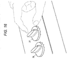
- the crane 1 includes the adjustment dials 26 and 27.
- the adjustment dials 26 and 27 are disposed within the reach of the operator. Therefore, the operator can freely turn the adjustment dials 26 and 27. Note that only the adjustment dial 26 is illustrated in Fig. 2 .
- the adjustment dial 27 may be provided at a position (for example, adjacent to the right side in Fig. 2 ) that is separated from and brought into contact with the adjustment dial 26.
- the adjustment dial 26 changes the notch depth Dn by selecting the notch depth coefficient ⁇ for automatic stop.
- the adjustment dial 27 changes the notch depth Dn by selecting the notch depth coefficient ⁇ for manual stop.
- the adjustment dial 26 corresponds to an example of a second filter characteristic setting unit.
- the adjustment dial 27 corresponds to an example of a first filter characteristic setting unit.
- the control device 20 uses the notch filter F set by the adjustment dial 26 to generate the automatic filtering control signal Sfa. Similarly, the control device 20 uses the notch filter F set by the adjustment dial 27 to generate the manual filtering control signal Sfm.
- the adjustment dial 26 can select 1 for the notch depth coefficient ⁇ .
- the control device 20 controls the actuators 51 to 54 on the basis of the automatic control signal Sa.
- the adjustment dial 27 can also select 1 for the notch depth coefficient ⁇ .
- the control device 20 controls the actuators 51 to 54 on the basis of the manual control signal Sm.
- the crane 1 is provided with the adjusting tools (the adjustment dials 26 and 27). Then, the strength of the notch filter F can be adjusted by operating the adjusters 26 and 27. According to the crane 1, it is possible to more finely match the operation feeling of the operator.
- the notch filter F is used as a filter that creates the filtering control signal Sf, but the invention is not limited thereto. That is, any band stop filter that can attenuate or reduce only a specific frequency band may be used. For example, a band limit filter or a band elimination filter may be used.
Landscapes
- Engineering & Computer Science (AREA)
- Mechanical Engineering (AREA)
- Automation & Control Theory (AREA)
- Control And Safety Of Cranes (AREA)
- Jib Cranes (AREA)
Abstract
Description
- The present invention relates to a crane.
- Conventionally, a crane has been known as a typical work vehicle. The crane is mainly composed of a traveling body and a turning body. The traveling body includes a plurality of wheels, and is configured to travel freely. The turning body includes a boom, a wire rope, a hook, and the like. Such a turning body is configured to be able to carry load. Further, such a crane is provided with an actuator for carrying a load and a control device for instructing an operating state of the actuator.
- By the way, a crane has been proposed in which a control device creates a filtering control signal and controls an actuator on the basis of the filtering control signal (see Patent Literature 1). Here, the filtering control signal means a signal obtained by applying a filter having a predetermined characteristic to a basic control signal of the actuator. For example, the filter may be a notch filter. The notch filter has a characteristic that the attenuation rate increases as it approaches the resonance frequency in an arbitrary range centered on the resonance frequency. The resonance frequency is calculated on the basis of the suspension length of the hook.
- Here, it is assumed that the above-mentioned actuator is a turning hydraulic motor and the turning operation of the boom is manually stopped. In this case, even if the operator stops the swinging motion of the boom, the turning operation continues for a while as the boom slows down. This is because the turning operation of the boom is not immediately stopped, but the deceleration section on the basis of the filtering control signal is provided to suppress the swing of the load. However, such a characteristic means that the turning operation of the boom does not match the operation by the operator, and there is a problem that the more experienced the operator, the greater the discomfort. Therefore, there is a demand for a crane that can select an operation characteristic with respect to a control mode of a load transport operation.
- Patent Literature 1:
JP 2015-151211 A - An object of the invention is to provide a crane capable of selecting an operation characteristic with respect to a control mode of a load transport operation.
- An aspect of a crane according to the invention includes a operable functional unit, an operation unit that receives an operation input for operating the operable functional unit, an actuator that drives the operable functional unit, a first generation unit that generates a first control signal for the actuator on the basis of the operation input, a switch unit that can be switched between a first state and a second state, a first filter unit that filters the first control signal to generate a second control signal when the switch unit is in the second state, and a control unit that controls the actuator on the basis of the first control signal when the switch unit is in the first state, and controls the actuator on the basis of the second control signal when the switch unit is in the second state.
- According to this invention, it is possible to provide a crane which can select an operation characteristic with respect to a control mode of a load transport operation.
-
-
Fig. 1 is a diagram illustrating a crane. -
Fig. 2 is a diagram illustrating the inside of a cabin. -
Fig. 3 is a diagram illustrating the configuration of a control system. -
Fig. 4 is a diagram illustrating frequency characteristics of a notch filter. -
Fig. 5 is a diagram illustrating a basic control signal and a filtering control signal. -
Fig. 6 is a diagram illustrating a transport allowable region and a transport restricted region at a work site. -
Fig. 7 is a diagram illustrating a control mode for automatically stopping or manually stopping the turning operation of a boom. -
Fig. 8 is a diagram illustrating a movement of a load when the turning operation of the boom is automatically stopped. -
Fig. 9 is a diagram illustrating a movement of the load when the turning operation of the boom is manually stopped. -
Fig. 10 is a diagram illustrating a movement of the load when a telescopic operation of the boom is automatically stopped. -
Fig. 11 is a diagram illustrating a movement of the load when the telescopic operation of the boom is manually stopped. -
Fig. 12 is a diagram illustrating a movement of the load when a derricking operation of the boom is automatically stopped. -
Fig. 13 is a diagram illustrating a movement of the load when the derricking operation of the boom is manually stopped. -
Fig. 14 is a diagram illustrating a movement of the load when a lifting operation of the hook is automatically stopped. -
Fig. 15 is a diagram illustrating a movement of the load when the lifting operation of the hook is manually stopped. -
Fig. 16 is a diagram illustrating an adjustment dial provided inside the cabin. - The technical ideas disclosed in the present application can be applied to various cranes in addition to a
crane 1 described below. - First, the
crane 1 will be described with reference toFig. 1 . - The
crane 1 is mainly composed of atraveling body 2 and a turningbody 3. - The traveling
body 2 includes a pair of left and rightfront tires 4 andrear tires 5. In addition, thetraveling body 2 is provided with anoutrigger 6 which is grounded and stabilized when carrying the load W. The turningbody 3 is supported on the upper part of thetraveling body 2. Such a turningbody 3 can be freely turned by an actuator. - The turning
body 3 is provided with aboom 7 so as to project forward from the rear part thereof. Therefore, theboom 7 can be freely turned by an actuator (see arrow A). Further, theboom 7 can be freely extended and contracted by an actuator (see arrow B). - Further, the
boom 7 can be freely raised and lowered by an actuator (see arrow C). In addition, awire rope 8 is stretched over theboom 7. Awinch 9 around which thewire rope 8 is wound is disposed on the base end side of theboom 7, and ahook 10 is suspended by thewire rope 8 on the tip end side of theboom 7. - The
winch 9 is configured integrally with the actuator, and allows thewire rope 8 to be wound and unwound. Therefore, thehook 10 can be freely raised and lowered by the actuator (see arrow D). The turningbody 3 is provided with acabin 11 on the side of theboom 7. Thewinch 9 corresponds to an example of a operable functional unit. - As illustrated in
Fig. 2 , aturning operation tool 21, atelescopic operation tool 22, aderricking operation tool 23, and awinding operation tool 24, which will be described later, are provided inside thecabin 11. Further, thecabin 11 is provided with achangeover switch 25. Each of theseoperation units 21 to 24 corresponds to an example of the operation unit. The operation unit receives an operation input for operating the operable functional unit. - Next, the control system will be described with reference to
Fig. 3 . However, the present control system is an example of a conceivable configuration and is not limited to this. - The control system is mainly configured by a
control device 20.Various operation tools 21 to 24 are connected to thecontrol device 20. Further, thecontrol device 20 is connected with a turningvalve 31, atelescopic valve 32, aderricking valve 33, and a windingvalve 34. - Further, the
control device 20 is connected to aweight sensor 40, a turningsensor 41, an extension/contraction sensor 42, aderricking sensor 43, and a windingsensor 44. Theweight sensor 40 can detect the weight of the load W. Therefore, thecontrol device 20 can recognize the weight of the load W. - As described above, the
boom 7 is freely turned by the actuator (see arrow A inFig. 1 ). In the present application, a turninghydraulic motor 51 corresponds to an example of the actuator. The turninghydraulic motor 51 is appropriately operated by the turningvalve 31 which is an electromagnetic proportional switching valve. - That is, the turning
hydraulic motor 51 is appropriately operated by the turningvalve 31 switching the flow direction of the hydraulic oil or adjusting the flow rate of the hydraulic oil. Further, the turning angle and the turning speed of theboom 7 are detected by the turningsensor 41. Therefore, thecontrol device 20 can recognize the turning angle and the turning speed of theboom 7. - Further, as described above, the
boom 7 can be freely expanded and contracted by the actuator (see arrow B inFig. 1 ). A telescopichydraulic cylinder 52 corresponds to an example of the actuator. The telescopichydraulic cylinder 52 is appropriately operated by thetelescopic valve 32 which is an electromagnetic proportional switching valve. - That is, the telescopic
hydraulic cylinder 52 is appropriately operated by thetelescopic valve 32 switching the flow direction of the hydraulic oil or adjusting the flow rate of the hydraulic oil. The extension/contraction length and extension/contraction speed of theboom 7 are detected by the extension/contraction sensor 42. Therefore, thecontrol device 20 can recognize the extension/contraction length and the extension/contraction speed of theboom 7. - Further, as described above, the
boom 7 is freely raised and lowered by the actuator (see arrow C inFig. 1 ). A derrickinghydraulic cylinder 53 corresponds to an example of the actuator. The derrickinghydraulic cylinder 53 is appropriately operated by thederricking valve 33 which is an electromagnetic proportional switching valve. - That is, the derricking
hydraulic cylinder 53 is appropriately operated by thederricking valve 33 switching the flow direction of the hydraulic oil or adjusting the flow rate of the hydraulic oil. The derricking angle and derricking speed of theboom 7 are detected by thederricking sensor 43. Therefore, thecontrol device 20 can recognize the derricking angle and derricking speed of theboom 7. - In addition, as described above, the
hook 10 is freely raised and lowered by the actuator (see arrow D inFig. 1 ). A windinghydraulic motor 54 corresponds to an example of the actuator. The windinghydraulic motor 54 is appropriately operated by the windingvalve 34 which is an electromagnetic proportional switching valve. - That is, the winding
hydraulic motor 54 is appropriately operated by the windingvalve 34 switching the flow direction of the hydraulic oil or adjusting the flow rate of the hydraulic oil. The suspension length L (seeFig. 1 ) and the lifting speed of thehook 10 are detected by the windingsensor 44. Therefore, thecontrol device 20 can recognize the suspension length L and the lifting speed of thehook 10. - By the way, the
control device 20 controls each actuator (51, 52, 53, 54) viavarious valves 31 to 34. Thecontrol device 20 includes a basic controlsignal creation unit 20a, a resonancefrequency calculation unit 20b, a filtercoefficient calculation unit 20c, and a filtering controlsignal creation unit 20d. The filtering controlsignal creation unit 20d may be regarded as an example of the first filter unit and the second filter unit. The first filter unit filters the first control signal to generate a second control signal. The second filter unit filters the third control signal to generate a fourth control signal. The first filter unit and the second filter unit may have different filter characteristics. That is, the filter coefficient of the first filter unit and the filter coefficient of the second filter unit may be different. The first filter unit and the second filter unit may have the same filter characteristics. - The basic control
signal creation unit 20a creates a basic control signal S that is a speed command for each actuator (51, 52, 53, 54) (seeFig. 5 ). The basic controlsignal creation unit 20a recognizes the operation amount and the operation speed of thevarious operation tools 21 to 24 by the operator, and creates the basic control signal S for each situation. - Specifically, the basic control
signal creation unit 20a creates a basic control signal S according to the operation amount and the operation speed of theturning operation tool 21, a basic control signal S according to the operation amount and the operation speed of thetelescopic operation tool 22, a basic control signal S according to the operation amount and operation speed of thederricking operation tool 23, and/or a basic control signal S according to the operation amount and operation speed of the windingoperation tool 24. The basic controlsignal creation unit 20a corresponds to an example of the first generation unit. - The resonance
frequency calculation unit 20b calculates a resonance frequency ω which is a swing frequency of the load W caused by the operation of each actuator (51, 52, 53, 54). The resonancefrequency calculation unit 20b recognizes the suspension length L of thehook 10 on the basis of the posture of theboom 7 and the unwinding amount of thewire rope 8, and calculates the resonance frequency ω for each situation. - Specifically, the resonance
frequency calculation unit 20b calculates the resonance frequency ω on the basis of the following expression using the suspension length L of thehook 10 and the gravitational acceleration g.
- The filter
coefficient calculation unit 20c calculates a center frequency coefficient ωn, a notch width coefficient ζ, and a notch depth coefficient δ of a transfer coefficient H(s) included in the notch filter F described later. The filtercoefficient calculation unit 20c calculates the corresponding center frequency coefficient ωn with the resonance frequency ω calculated by the resonancefrequency calculation unit 20b as a center. - In addition, the filter
coefficient calculation unit 20c calculates the notch width coefficient ζ and the notch depth coefficient δ corresponding to each basic control signal S. The transfer coefficient H(s) is represented by the following expression using the center frequency coefficient ωn, the notch width coefficient ζ, and the notch depth coefficient δ. The transfer coefficient H(s) is also called a filter characteristic. If the parameters of the transfer coefficient H(s) are different, it may be considered that the filter characteristics of the notch filter F are different.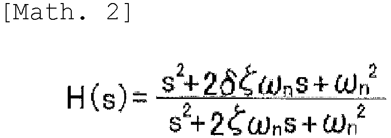
- The filtering control
signal creation unit 20d creates the notch filter F, and also applies the notch filter F to the basic control signal S to create a filtering control signal Sf (seeFig. 5 ). The filtering controlsignal creation unit 20d creates the notch filter F by acquiring the various coefficients ωn, ζ, and δ from the filtercoefficient calculation unit 20c. - Further, the filtering control
signal creation unit 20d acquires the basic control signal S from the basic controlsignal creation unit 20a, applies the notch filter F to the basic control signal S, and creates the filtering control signal Sf. - Specifically, the filtering control
signal creation unit 20d creates the filtering control signal Sf from the basic control signal S and the notch filter F according to the operation amount of theturning operation tool 21 and the like. Further, the filtering controlsignal creation unit 20d creates the filtering control signal Sf on the basis of the basic control signal S and the notch filter F according to the operation amount of thetelescopic operation tool 22 and the like. The filtering controlsignal creation unit 20d creates the filtering control signal Sf on the basis of the basic control signal S and the notch filter F corresponding to the operation amount of thederricking operation tool 23 and the like. Further, the filtering controlsignal creation unit 20d generates the filtering control signal Sf on the basis of the basic control signal S and the notch filter F according to the operation amount of the windingoperation tool 24 and the like. - With such a configuration, the
control device 20 controls thevarious valves 31 to 34 on the basis of the filtering control signal Sf. As a result, thecontrol device 20 controls each actuator (51, 52, 53, 54) on the basis of the filtering control signal Sf. - Next, the notch filter F and the filtering control signal Sf will be described with reference to
Figs. 4 and5 . - The notch filter F has a characteristic that the attenuation rate increases as it approaches the resonance frequency ω in an arbitrary range centered on the resonance frequency ω. An arbitrary range centered on the resonance frequency ω is represented as a notch width Bn. The difference of the attenuation amount in the notch width Bn is represented as a notch depth Dn.
- Therefore, the notch filter F is specified by the resonance frequency ω, the notch width Bn, and the notch depth Dn. The notch depth Dn is determined on the basis of the notch depth coefficient δ. Therefore, when the notch depth coefficient δ = 0, the gain characteristic at the resonance frequency ω is -∞ dB, and when the notch depth coefficient δ = 1, the gain characteristic at the resonance frequency ω is 0 dB.
- The filtering control signal Sf is a speed command transmitted to each actuator (51, 52, 53, 54). The filtering control signal Sf corresponding to the acceleration of the
boom 7 or the like has a characteristic that the acceleration is gentler than the basic control signal S, and temporarily causes deceleration and then causes acceleration again (see part X inFig. 5 ). - Here, the reason for temporarily decelerating is to suppress the swing of the load W during acceleration. Further, the filtering control signal Sf corresponding to deceleration of the
boom 7 or the like has a characteristic that the deceleration is gentler or similar to that of the basic control signal S, and temporarily causes acceleration and then causes deceleration again (See part Y inFig. 5 ). Here, the reason for temporarily accelerating is to suppress the swing of the load W during deceleration. - Next, a transport allowable region Rp and a transport restricted region Rr at the work site will be described with reference to
Fig. 6 . - The transport allowable region Rp represents a region where the transport of the load W is permitted. In the transport allowable region Rp, the
boom 7 is also allowed to move. Further, in the transport allowable region Rp, the notch depth coefficient δ is selectable within the range of 0 to 1. - When the notch depth coefficient δ is 0 or a numerical value close to 0, a slow reaction to the operation of the operator occurs, and the swing of the load W can be suppressed. On the other hand, when the notch depth coefficient δ is 1 or a numerical value close to 1, an agile reaction to the operation of the operator occurs, and it becomes possible to match the operation feeling of the operator.
- The transport restricted region Rr represents a region where transport of the load W is not permitted. In the transport restricted region Rr, the
boom 7 is not allowed to move (enter). In addition, since the load W and theboom 7 do not enter in the transport restricted region Rr, the notch depth coefficient δ and the like cannot be determined. - Further, the transport restricted region Rr is provided so as to surround an obstacle B and the like. Therefore, it is possible to prevent the load W and the
boom 7 from colliding with the obstacle B or the like. In addition, when the load W or theboom 7 in the transport allowable region Rp is moving toward the transport restricted region Rr, the transport operation is automatically stopped. - Hereinafter, a control mode for automatically stopping or manually stopping the transport operation of the load W will be described with reference to
Fig. 7 . - First, an example in which the load W is moving toward the transport restricted region Rr due to the turning operation of the
boom 7 will be described. Here, the description will be given with reference toFigs. 8 and9 together withFig. 7 . In this example, theboom 7 corresponds to an example of the operable functional unit. - In step S11, the
control device 20 determines whether the automatic stop signal has been input. The automatic stop signal is created when the load W or theboom 7 approaches the transport restricted region Rr. When the automatic stop signal is input ("YES" in step S11), the control process proceeds to step S12, and when the automatic stop signal is not input ("NO" in step S11), the control process proceeds to step S14. - In step S12, the
control device 20 creates an automatic control signal Sa for the turning hydraulic motor 51 (seeFig. 8 ). The automatic control signal Sa is the basic control signal S created at the time of automatic stop. The automatic control signal Sa corresponds to an example of the third control signal. The automatic control signal Sa is created on the basis of the turning speed of theboom 7, the weight of the load W, and the like. The automatic control signal Sa is created on the basis of the program used at the time of automatic stop. The program is stored in thecontrol device 20 in advance. In thecontrol device 20, the part that generates the automatic control signal Sa may be regarded as an example of a second generation unit. - In step S13, the
control device 20 creates a filtering control signal Sf (hereinafter referred to as "automatic filtering control signal Sfa") by applying the notch filter F to the automatic control signal Sa (third control signal) (seeFig. 8 ). The notch filter F at this time is created on the basis of the notch depth coefficient δ that is arbitrarily set. The automatic filtering control signal Sfa corresponds to an example of the fourth control signal. - Then, the
control device 20 controls the turninghydraulic motor 51 on the basis of the automatic filtering control signal Sfa. As a result, for example, it is possible to realize the control content that gives priority to suppressing the swing of the load W. In this case, when the turning speed of theboom 7 is reduced, the load W starts to swing due to inertia (see (A) inFig. 8 ). - Therefore, the turning speed of the
boom 7 is temporarily increased to catch up with theboom 7 and suppress the swing of the load W (see (B) inFig. 8 ). Thereafter, the turning speed is decelerated again while the swing of the load W is suppressed (see (C) inFig. 8 ). Further, the notch depth coefficient δ of the notch filter F is freely changed by anadjustment dial 26 described later. - In addition, the flow rate of the load W and the boom 7 (the moving distance from when the turning operation is stopped until the turning operation is stopped) is determined to be within an allowable flow rate Pd. The operator can arbitrarily set the allowable flow rate Pd.
- By the way, in step S14, the
control device 20 determines whether a manual stop signal is input. The manual stop signal is created when the operator operates the turningoperation tool 21 to stop the turning operation of theboom 7. When the manual stop signal is input ("YES" in step S14), the control process proceeds to step S15, and when the manual stop signal is not input ("NO" in step S14), the control process returns to step S11. - In step S15, the
control device 20 creates a manual control signal Sm for the turning hydraulic motor 51 (seeFig. 9 ). The manual control signal Sm indicates the basic control signal S created at the time of manual stop. The manual control signal Sm is created on the basis of the operation amount and the operation speed of theturning operation tool 21 by the operator. - Further, the manual control signal Sm is created on the basis of a program used when manually stopping. The program is stored in the
control device 20 in advance. - In step S16, the
control device 20 determines whether thechangeover switch 25 is "ON" or "OFF". Thechangeover switch 25 can be freely changed by the operator. When thechangeover switch 25 is "ON" ("YES" in step S16), the control process proceeds to step S17, and when thechangeover switch 25 is "OFF" ("NO" in step S16), the control process proceeds to step S18. - Further, the state in which the
changeover switch 25 is "OFF" is defined as the first state of thechangeover switch 25. On the other hand, the state in which thechangeover switch 25 is "ON" is defined as the second state of thechangeover switch 25. Thechangeover switch 25 corresponds to an example of a switch unit. - In step S17, the
control device 20 applies the notch filter F to the manual control signal Sm to create the filtering control signal Sf (hereinafter, referred to as "manual filtering control signal Sfm") (seeFig. 9 ). The notch filter F at this time is also created on the basis of the notch depth coefficient δ that is arbitrarily set. - The notch filter F used in step S13 and the notch filter F used in step S17 may be the same filter or different filters. As an example, by the notch filter F used in step S17, the ratio of frequency components attenuated from the manual control signal Sm may be smaller than the ratio of frequency components attenuated from the automatic control signal Sa by the notch filter F used in step S13. In other words, the ratio of frequency components attenuated from the manual control signal Sm when the actuator is controlled by manual control (the case of step S17) may be smaller than the ratio of frequency components attenuated from the automatic control signal Sa when the actuator is controlled by automatic control (the case of step S13).
- Then, the
control device 20 controls the turninghydraulic motor 51 on the basis of the manual filtering control signal Sfm. As a result, it is possible to realize the control content that gives priority to matching with the operation feeling of the operator rather than suppressing the swing of the load W, for example. - In this case, when the turning speed of the
boom 7 is reduced, the load W starts to swing due to inertia (see (A) inFig. 9 ). Then, while the turning speed of theboom 7 is slightly increased or is not increased, the turning speed of theboom 7 is decelerated as it is (see (B) inFig. 9 ). - The notch depth coefficient δ of the notch filter F is freely changed by an
adjustment dial 27 described later. In addition, the swing amount of the load W is determined to be within an allowable swing width Px. The operator can arbitrarily set the allowable swing width Px. - On the other hand, in step S18, the
control device 20 controls the turninghydraulic motor 51 on the basis of the manual control signal Sm. That is, thecontrol device 20 controls the turninghydraulic motor 51 on the basis of the manual control signal Sm as it is, without creating the manual filtering control signal Sfm. - As a result, it is possible to realize the control content that gives the highest priority to matching the operation feeling of the operator without considering the swing of the load W. In this case, in order to suppress the swing of the load W, it is necessary for the operator to operate the
turning operation tool 21 to temporarily increase the turning speed of theboom 7 and make the load W, which has started to swing, catch up with theboom 7. Such an operation can be performed by a skilled operator. - As described above, the
crane 1 is provided with the actuator (the turning hydraulic motor 51) used for carrying the load W, thecontrol device 20 for instructing the operating state of theactuator 51, and a switch (the changeover switch 25) which is connected to thecontrol device 20 to switch the control mode of theactuator 51. - Then, when the
switch 25 selects one (when theswitch 25 is in the OFF state and the first state of the switch), thecontrol device 20 controls theactuator 51 on the basis of the basic control signal S (manual control signal Sm) of theactuator 51 to stop the transport operation. - Further, when the
switch 25 selects the other (when theswitch 25 is in the ON state and the second state of the switch), thecontrol device 20 applies the notch filter F to the basic control signal Sm of theactuator 51 to create the filtering control signal Sf (manual filtering control signal Sfm). Then, thecontrol device 20 controls theactuator 51 on the basis of the created filtering control signal Sfm to stop the transport operation. According to such acrane 1, the operation characteristics can be selected for the control mode when the transport operation of the load W is stopped. - Specifically, in the
crane 1, the actuator (the turning hydraulic motor 51) is a hydraulic motor that turns theboom 7. When the switch (changeover switch 25) selects one (thechangeover switch 25 is in the OFF state), thecontrol device 20 controls thehydraulic motor 51 on the basis of the basic control signal S (manual control signal Sm) of thehydraulic motor 51 to stop the turning operation. - When the
switch 25 selects the other (thechangeover switch 25 is in the ON state), thecontrol device 20 applies the notch filter F to the basic control signal Sm of thehydraulic motor 51 to create the filtering control signal Sf (manual filtering control signal Sfm). Then, thecontrol device 20 controls thehydraulic motor 51 on the basis of the created filtering control signal Sfm to stop the turning operation. According to such acrane 1, the operation characteristics can be selected for the control mode when the turning operation of theboom 7 is stopped. - In the
crane 1, the swing frequency of the load W is set to the resonance frequency ω in order to suppress the swing of the load W caused by the turning operation of theboom 7. However, in order to suppress the swing of theboom 7 itself caused by the turning operation of theboom 7, the swing frequency of theboom 7 may be set to the resonance frequency ω. Further, the resonance frequency ω may be set in consideration of both the swing frequency of the load W and the swing frequency of theboom 7. - In addition, in the
crane 1, the operator operates thechangeover switch 25 to select the control mode, but the invention is not limited thereto. For example, thechangeover switch 25 may be incorporated in an arithmetic device of thecontrol device 20 and may be configured in advance so as to select a desired control mode. - Alternatively, the configuration may be such that an appropriate control mode is automatically selected according to the situation. That is, the
changeover switch 25 is not limited to being manually operated. - Next, an example in which the load W is moving toward the transport restricted region Rr due to the telescopic operation of the
boom 7 will be described. Here, the description will be given with reference toFigs. 10 and11 together withFig. 7 . Although the telescopic operation of theboom 7 is described as an extension operation, the same applies to a contraction operation. In this example, theboom 7 corresponds to an example of the operable unctional unit. - In step S11, the
control device 20 determines whether the automatic stop signal has been input. The automatic stop signal is created when the load W or theboom 7 approaches the transport restricted region Rr. When the automatic stop signal is input ("YES" in step S11), the control process proceeds to step S12, and when the automatic stop signal is not input ("NO" in step S11), the control process proceeds to step S14. - In step S12, the
control device 20 creates the automatic control signal Sa for the telescopic hydraulic cylinder 52 (seeFig. 10 ). The automatic control signal Sa is the basic control signal S created at the time of automatic stop. The automatic control signal Sa is created on the basis of the extension speed of theboom 7, the weight of the load W, and the like. - The automatic control signal Sa is created on the basis of the program used at the time of automatic stop. The program is stored in the
control device 20 in advance. - In step S13, the
control device 20 applies the notch filter F to the automatic control signal Sa to create the filtering control signal Sf (hereinafter, referred to as "automatic filtering control signal Sfa") (seeFig. 10 ). The notch filter F at this time is created on the basis of the notch depth coefficient δ that is arbitrarily set. - Then, the
control device 20 controls the telescopichydraulic cylinder 52 on the basis of the automatic filtering control signal Sfa. As a result, for example, it is possible to realize the control content that gives priority to suppressing the swing of the load W. In this case, when the extension speed of theboom 7 is reduced, the load W starts to swing due to inertia (see (A) inFig. 10 ) . - Therefore, the extension speed of the
boom 7 is temporarily increased to catch up with theboom 7 and suppress the swing of the load W (see (B) inFig. 10 ). Thereafter, the load W is decelerated again while the swing is suppressed (see (C) inFig. 10 ). - Further, the notch depth coefficient δ of the notch filter F is freely changed by the
adjustment dial 26 described later. In addition, the flow rate of the load W and the boom 7 (the moving distance from when the turning operation is stopped until the extension operation is stopped) is determined to be within an allowable flow rate Pd. The operator can arbitrarily set the allowable flow rate Pd. - By the way, in step S14, the
control device 20 determines whether the manual stop signal is input. The manual stop signal is created when the operator operates thetelescopic operation tool 22 to stop the extension operation of theboom 7. When the manual stop signal is input ("YES" in step S14), the control process proceeds to step S15, and when the manual stop signal is not input ("NO" in step S14), the control process returns to step S11. - In step S15, the
control device 20 creates the manual control signal Sm for the telescopic hydraulic cylinder 52 (seeFig. 11 ). The manual control signal Sm is the basic control signal S created at the time of manual stop. The manual control signal Sm is created on the basis of the operation amount and the operation speed of thetelescopic operation tool 22 by the operator. - Further, the manual control signal Sm is created on the basis of a program used when manually stopping. The program is stored in the
control device 20 in advance. - In step S16, the
control device 20 determines whether thechangeover switch 25 is "ON" or "OFF". Thechangeover switch 25 can be freely changed by the operator. When thechangeover switch 25 is "ON" ("YES" in step S16), the control process proceeds to step S17, and when thechangeover switch 25 is "OFF" ("NO" in step S16), the control process proceeds to step S18. - In step S17, the
control device 20 applies the notch filter F to the manual control signal Sm to create the filtering control signal Sf (hereinafter referred to as "manual filtering control signal Sfm") (seeFig. 11 ). The notch filter F at this time is also created on the basis of the notch depth coefficient δ that is arbitrarily set. - Then, the
control device 20 controls the telescopichydraulic cylinder 52 on the basis of the manual filtering control signal Sfm. As a result, it is possible to realize the control content that gives priority to matching with the operation feeling of the operator rather than suppressing the swing of the load W, for example. - In this case, when the extension speed of the
boom 7 is reduced, the load W starts to swing due to inertia (see (A) inFig. 11 ). Then, while the extension speed of theboom 7 is slightly increased or is not increased, the extension speed of theboom 7 is decelerated as it is (see (B) inFig. 11 ). - The notch depth coefficient δ of the notch filter F is freely changed by the
adjustment dial 27 described later. In addition, the swing amount of the load W is determined to be within the allowable swing width Px. The operator can arbitrarily set the allowable swing width Px. - On the other hand, in step S18, the
control device 20 controls the telescopichydraulic cylinder 52 on the basis of the manual control signal Sm. That is, thecontrol device 20 controls the telescopichydraulic cylinder 52 on the basis of the manual control signal Sm as it is, without creating the manual filtering control signal Sfm. As a result, it is possible to realize the control content that gives the highest priority to matching the operation feeling of the operator without considering the swing of the load W. - In this case, in order to suppress the swing of the load W, it is necessary for the operator to operate the
telescopic operation tool 22 to temporarily increase the extension speed of theboom 7 and make the load W, which has started to swing, catch up with theboom 7. Such an operation can be performed by a skilled operator. - As described above, the
crane 1 is provided with the actuator (the telescopic hydraulic cylinder 52) used for carrying the load W, thecontrol device 20 for instructing the operating state of theactuator 52, and a switch (the changeover switch 25) which is connected to thecontrol device 20 to switch the control mode of theactuator 52. - Then, when the
switch 25 selects one, thecontrol device 20 controls theactuator 52 on the basis of the basic control signal S (manual control signal Sm) of theactuator 52 to stop the transport operation. - Further, when the
switch 25 selects the other, thecontrol device 20 applies the notch filter F to the basic control signal Sm of theactuator 52 to create the filtering control signal Sf (manual filtering control signal Sfm), and controls theactuator 52 on the basis of the filtering control signal Sfm to stop the transport operation. According to thecrane 1, the operation characteristics can be selected for the control mode when the transport operation of the load W is stopped. - More specifically, in the
crane 1, the actuator (the telescopic hydraulic cylinder 52) is a hydraulic cylinder that expands and contracts theboom 7. When the switch (the changeover switch 25) selects one, thecontrol device 20 controls thehydraulic cylinder 52 on the basis of the basic control signal S (manual control signal Sm) of thehydraulic cylinder 52 to stop the telescopic operation. - Further, when the
switch 25 selects the other, thecontrol device 20 applies the notch filter F to the basic control signal Sm of thehydraulic cylinder 52 to create the filtering control signal Sf (manual filtering control signal Sfm), and controls thehydraulic cylinder 52 on the basis of the filtering control signal Sfm to stop the telescopic operation. According to such acrane 1, the operation characteristics can be selected for the control mode when the telescopic operation of theboom 7 is stopped. - In the
crane 1, the swing frequency of the load W is set to the resonance frequency ω in order to suppress the swing of the load W caused by the telescopic operation of theboom 7. However, in order to suppress the swing of theboom 7 itself caused by the telescopic operation of theboom 7, the swing frequency of theboom 7 may be set to the resonance frequency ω. Further, the resonance frequency ω may be set in consideration of both the swing frequency of the load W and the swing frequency of theboom 7. - In addition, in the
crane 1, the operator operates thechangeover switch 25 to select the control mode, but the invention is not limited thereto. For example, thechangeover switch 25 may be incorporated in the arithmetic device of thecontrol device 20 and may be configured in advance so as to select a desired control mode. Alternatively, the configuration may be such that an appropriate control mode is automatically selected according to the situation. That is, thechangeover switch 25 is not limited to being manually operated. - Next, an example in which the load W is moving toward the transport restricted region Rr due to the derricking operation of the
boom 7 will be described. Here, the description will be given with reference toFigs. 12 and13 together withFig. 7 . In addition, the derricking operation of theboom 7 will be described as the raising operation, but the same applies to the lowering operation. In this example, theboom 7 corresponds to an example of the operable functional unit. - In step S11, the
control device 20 determines whether the automatic stop signal has been input. The automatic stop signal is created when the load W or theboom 7 approaches the transport restricted region Rr. When the automatic stop signal is input ("YES" in step S11), the control process proceeds to step S12, and when the automatic stop signal is not input ("NO" in step S11), the control process proceeds to step S14. - In step S12, the
control device 20 creates the automatic control signal Sa for the derricking hydraulic cylinder 53 (seeFig. 12 ). The automatic control signal Sa is the basic control signal S created at the time of automatic stop. - The automatic control signal Sa is created on the basis of the rising speed of the
boom 7, the weight of the load W, and the like. The automatic control signal Sa is created on the basis of the program used at the time of automatic stop. The program is stored in thecontrol device 20 in advance. - In step S13, the
control device 20 applies the notch filter F to the automatic control signal Sa to create the filtering control signal Sf (hereinafter, referred to as "automatic filtering control signal Sfa") (seeFig. 12 ). The notch filter F at this time is created on the basis of the notch depth coefficient δ that is arbitrarily set. - Then, the
control device 20 controls the derrickinghydraulic cylinder 53 on the basis of the automatic filtering control signal Sfa. As a result, for example, it is possible to realize the control content that gives priority to suppressing the swing of the load W. In this case, when the rising speed of theboom 7 is reduced, the load W starts to swing due to inertia (starts to swing due to the bending of the wire rope 8: see (A) inFig. 12 ). - Therefore, the rising speed of the
boom 7 is temporarily increased to stretch thewire rope 8, so that the swing of the load W is suppressed (see (B) inFig. 12 ). Thereafter, the load W is decelerated again while the swing is suppressed (see (C) inFig. 12 ). - Further, the notch depth coefficient δ of the notch filter F is freely changed by the
adjustment dial 26 described later. In addition, the flow rate of the load W and the boom 7 (the moving distance from when the turning operation is stopped until the raising operation is stopped) is determined to be within an allowable flow rate Pd. The operator can arbitrarily set the allowable flow rate Pd. - By the way, in step S14, the
control device 20 determines whether the manual stop signal is input. The manual stop signal is created when the operator operates thederricking operation tool 23 to stop the raising operation of theboom 7. When the manual stop signal is input ("YES" in step S14), the control process proceeds to step S15, and when the manual stop signal is not input ("NO" in step S14), the control process returns to step S11. - In step S15, the
control device 20 creates the manual control signal Sm for the derricking hydraulic cylinder 53 (seeFig. 13 ). The manual control signal Sm is the basic control signal S created at the time of manual stop. The manual control signal Sm is created on the basis of the operation amount and the operation speed of thederricking operation tool 23 by the operator. Further, the manual control signal Sm is created on the basis of a program used when manually stopping. The program is stored in thecontrol device 20 in advance. - In step S16, the
control device 20 determines whether thechangeover switch 25 is "ON" or "OFF". Thechangeover switch 25 can be freely changed by the operator. When thechangeover switch 25 is "ON" ("YES" in step S16), the control process proceeds to step S17, and when thechangeover switch 25 is "OFF" ("NO" in step S16), the control process proceeds to step S18. - In step S17, the
control device 20 applies the notch filter F to the manual control signal Sm to create the filtering control signal Sf (hereinafter referred to as "manual filtering control signal Sfm") (seeFig. 13 ). The notch filter F at this time is also created on the basis of the notch depth coefficient δ that is arbitrarily set. - Then, the
control device 20 controls the derrickinghydraulic cylinder 53 on the basis of the manual filtering control signal Sfm. As a result, it is possible to realize the control content that gives priority to matching with the operation feeling of the operator rather than suppressing the swing of the load W, for example. - In this case, when the rising speed of the
boom 7 is reduced, the load W starts to swing due to inertia (starts to swing due to the bending of the wire rope 8: see (A) inFig. 13 ). Then, while the rising speed of theboom 7 is slightly increased or is not increased, the rising speed of theboom 7 is decelerated as it is (see (B) inFig. 13 ). The notch depth coefficient δ of the notch filter F is freely changed by theadjustment dial 27 described later. In addition, the swing amount of the load W is determined to be within the allowable swing width Px. The operator can arbitrarily set the allowable swing width Px. - On the other hand, in step S18, the
control device 20 controls the derrickinghydraulic cylinder 53 on the basis of the manual control signal Sm. That is, thecontrol device 20 controls the derrickinghydraulic cylinder 53 on the basis of the manual control signal Sm as it is, without creating the manual filtering control signal Sfm. - As a result, it is possible to realize the control content that gives the highest priority to matching the operation feeling of the operator without considering the swing of the load W. In this case, in order to suppress the swing of the load W, it is necessary for the operator to operate the
derricking operation tool 23 to temporarily increase the rising speed of theboom 7 and stretch thewire rope 8 which has started to bend. Such an operation can be performed by a skilled operator. - As described above, the
crane 1 is provided with the actuator (the derricking hydraulic cylinder 53) used for carrying the load W, thecontrol device 20 for instructing the operating state of theactuator 53, and a switch (the changeover switch 25) which is connected to thecontrol device 20 to switch the control mode of theactuator 53. - Then, when the
switch 25 selects one, thecontrol device 20 controls theactuator 53 on the basis of the basic control signal S (manual control signal Sm) of theactuator 53 to stop the transport operation. - Further, when the
switch 25 selects the other, thecontrol device 20 applies the notch filter F to the basic control signal Sm of theactuator 53 to create the filtering control signal Sf (manual filtering control signal Sfm), and controls theactuator 53 on the basis of the filtering control signal Sfm to stop the transport operation. According to such acrane 1, the operation characteristics can be selected for the control mode when the transport operation of the load W is stopped. - More specifically, in the
crane 1, the actuator (the derricking hydraulic cylinder 53) is a hydraulic cylinder that raises theboom 7. When the switch (the changeover switch 25) selects one, thecontrol device 20 controls thehydraulic cylinder 53 on the basis of the basic control signal S (manual control signal Sm) of thehydraulic cylinder 53 to stop the derricking operation. - Further, when the
switch 25 selects the other, thecontrol device 20 applies the notch filter F to the basic control signal Sm of thehydraulic cylinder 53 to create the filtering control signal Sf (manual filtering control signal Sfm), and controls thehydraulic cylinder 53 on the basis of the filtering control signal Sfm to stop the derricking operation. According to thecrane 1, the operation characteristics can be selected for the control mode when the derricking operation of theboom 7 is stopped. - In the
crane 1, the swing frequency of the load W is set to the resonance frequency ω in order to suppress the swing of the load W caused by the derricking operation of theboom 7. However, in order to suppress the swing of theboom 7 itself caused by the derricking operation of theboom 7, the swing frequency of theboom 7 may be set to the resonance frequency ω. Further, the resonance frequency ω may be set in consideration of both the swing frequency of the load W and the swing frequency of theboom 7. - In addition, in the
crane 1, the operator operates thechangeover switch 25 to select the control mode, but the invention is not limited thereto. For example, thechangeover switch 25 may be incorporated in the arithmetic device of thecontrol device 20 and may be configured in advance so as to select a desired control mode. Alternatively, the configuration may be such that an appropriate control mode is automatically selected according to the situation. That is, thechangeover switch 25 is not limited to being manually operated. - Next, an example in which the load W is moving toward the transport restricted region Rr due to the lifting operation of the
hook 10 will be described. Here, the description will be given with reference toFigs. 14 and15 together withFig. 7 . Although the lifting operation of thehook 10 is described as an ascending operation, the same goes for the descending operation. In this example, thewinch 9 for lifting thehook 10 corresponds to an example of the operable functional unit. - In step S11, the
control device 20 determines whether the automatic stop signal has been input. The automatic stop signal is created when the load W or theboom 7 approaches the transport restricted region Rr. When the automatic stop signal is input, the process proceeds to step S12, and when the automatic stop signal is not input, the process proceeds to step S14. - In step S12, the
control device 20 creates an automatic control signal Sa for the winding hydraulic motor 54 (seeFig. 14 ). The automatic control signal Sa is the basic control signal S created at the time of automatic stop. The automatic control signal Sa is created on the basis of the ascending speed of thehook 10, the weight of the load W, and the like. The automatic control signal Sa is created on the basis of the program used at the time of automatic stop. The program is stored in thecontrol device 20 in advance. - In step S13, the
control device 20 applies the notch filter F to the automatic control signal Sa to create the filtering control signal Sf (hereinafter, referred to as "automatic filtering control signal Sfa") (seeFig. 14 ). The notch filter F at this time is created on the basis of the notch depth coefficient δ that is arbitrarily set. - Then, the
control device 20 controls the windinghydraulic motor 54 on the basis of the automatic filtering control signal Sfa. As a result, for example, it is possible to realize the control content that gives priority to suppressing the swing of the load W. In this case, when the ascending speed of thehook 10 is reduced, the load W starts to swing due to inertia (starts to swing due to the bending of the wire rope 8: see (A) inFig. 14 ). - Therefore, the ascending speed of the
hook 10 is temporarily increased to stretch thewire rope 8, so that the swing of the load W is suppressed (see (B) inFig. 14 ). Thereafter, the load W is decelerated again while the swing is suppressed (see (C) inFig. 14 ). - Further, the notch depth coefficient δ of the notch filter F is freely changed by the
adjustment dial 26 described later. In addition, the flow rate of the load W (the moving distance from when the turning operation is stopped until the ascending operation is stopped) is determined to be within an allowable flow rate Pd. The operator can arbitrarily set the allowable flow rate Pd. - By the way, in step S14, the
control device 20 determines whether the manual stop signal is input. The manual stop signal is created when the operator operates the windingoperation tool 24 to stop the ascending operation of thehook 10. When the manual stop signal is input ("YES" in step S14), the control process proceeds to step S15, and when the manual stop signal is not input ("NO" in step S14), the control process returns to step S11. - In step S15, the
control device 20 creates a manual control signal Sm for the winding hydraulic motor 54 (seeFig. 15 ). The manual control signal Sm is the basic control signal S created at the time of manual stop. The manual control signal Sm is created on the basis of the operation amount and the operation speed of the windingoperation tool 24 by the operator. Further, the manual control signal Sm is created on the basis of a program used when manually stopping. The program is stored in thecontrol device 20 in advance. - In step S16, the
control device 20 determines whether thechangeover switch 25 is "ON" or "OFF". Thechangeover switch 25 can be freely changed by the operator. When thechangeover switch 25 is "ON" ("YES" in step S16), the control process proceeds to step S17, and when thechangeover switch 25 is "OFF" ("NO" in step S16), the control process proceeds to step S18. - In step S17, the
control device 20 applies the notch filter F to the manual control signal Sm to create the filtering control signal Sf (hereinafter referred to as "manual filtering control signal Sfm") (seeFig. 15 ). The notch filter F at this time is also created on the basis of the notch depth coefficient δ that is arbitrarily set. Then, thecontrol device 20 controls the windinghydraulic motor 54 on the basis of the manual filtering control signal Sfm. As a result, it is possible to realize the control content that gives priority to matching with the operation feeling of the operator rather than suppressing the swing of the load W, for example. - In this case, when the ascending speed of the
hook 10 is reduced, the load W starts to swing due to inertia (starts to swing due to the bending of the wire rope 8: see (A) inFig. 15 ). Then, the ascending speed of thehook 10 is slightly increased or is not increased, the ascending speed of thehook 10 is decelerated as it is (see (B) inFig. 15 ). - The notch depth coefficient δ of the notch filter F is freely changed by the
adjustment dial 27 described later. In addition, the swing amount of the load W is determined to be within the allowable swing width Px. The operator can arbitrarily set the allowable swing width Px. - On the other hand, in step S18, the
control device 20 controls the windinghydraulic motor 54 on the basis of the manual control signal Sm. That is, thecontrol device 20 controls the windinghydraulic motor 54 on the basis of the manual control signal Sm as it is, without creating the manual filtering control signal Sfm. - As a result, it is possible to realize the control content that gives the highest priority to matching the operation feeling of the operator without considering the swing of the load W. In this case, in order to suppress the swing of the load W, it is necessary for the operator to operate the winding
operation tool 24 to temporarily increase the ascending speed of thehook 10 and stretch thewire rope 8 which has started to bend. Such an operation can be performed by a skilled operator. - As described above, the
crane 1 is provided with the actuator (the winding hydraulic motor 54) used for carrying the load W, thecontrol device 20 for instructing the operating state of theactuator 54, and a switch (the changeover switch 25) which is connected to thecontrol device 20 to switch the control mode of theactuator 54. - Then, when the
switch 25 selects one, thecontrol device 20 controls theactuator 54 on the basis of the basic control signal S (manual control signal Sm) of theactuator 54 to stop the transport operation. Further, when theswitch 25 selects the other, thecontrol device 20 applies the notch filter F to the basic control signal Sm of theactuator 54 to create the filtering control signal Sf (manual filtering control signal Sfm), and controls theactuator 54 on the basis of the filtering control signal Sfm to stop the transport operation. According to thecrane 1, the operation characteristics can be arbitrarily adjusted for the control mode when the transport operation of the load W is manually stopped. - Specifically, in the
crane 1, the actuator (the winding hydraulic motor 54) is a hydraulic motor that makes thehook 10 ascend and descend. When the switch (the changeover switch 25) selects one, thecontrol device 20 controls thehydraulic motor 54 on the basis of the basic control signal S (manual control signal Sm) of thehydraulic motor 54 to stop the lifting operation. - When the
switch 25 selects the other, thecontrol device 20 applies the notch filter F to the basic control signal Sm of thehydraulic motor 54 to create the filtering control signal Sf (manual filtering control signal Sfm). Then, thecontrol device 20 controls thehydraulic motor 54 on the basis of the filtering control signal Sfm to stop the lifting operation. According to such acrane 1, the operation characteristics can be selected for the control mode when the lifting operation of thehook 10 is stopped. - In the
crane 1, the swing frequency of the load W is set to the resonance frequency ω in order to suppress the swing of the load W caused by the lifting operation of thehook 10. However, in order to suppress the swing of theboom 7 itself caused by the lifting operation of thehook 10, the swing frequency of theboom 7 may be set to the resonance frequency ω. Further, the resonance frequency ω may be set in consideration of both the swing frequency of the load W and the swing frequency of theboom 7. - In addition, in the
crane 1, the operator operates thechangeover switch 25 to select the control mode, but the invention is not limited thereto. For example, thechangeover switch 25 may be incorporated in the arithmetic device of thecontrol device 20 and may be configured in advance so as to select a desired control mode. Alternatively, the configuration may be such that an appropriate control mode is automatically selected according to the situation. That is, thechangeover switch 25 is not limited to being manually operated. - Next, other characteristic points of the
crane 1 will be described. - As illustrated in
Fig. 16 , thecrane 1 includes the adjustment dials 26 and 27. The adjustment dials 26 and 27 are disposed within the reach of the operator. Therefore, the operator can freely turn the adjustment dials 26 and 27. Note that only theadjustment dial 26 is illustrated inFig. 2 . InFig. 2 , theadjustment dial 27 may be provided at a position (for example, adjacent to the right side inFig. 2 ) that is separated from and brought into contact with theadjustment dial 26. - The
adjustment dial 26 changes the notch depth Dn by selecting the notch depth coefficient δ for automatic stop. Theadjustment dial 27 changes the notch depth Dn by selecting the notch depth coefficient δ for manual stop. Theadjustment dial 26 corresponds to an example of a second filter characteristic setting unit. Theadjustment dial 27 corresponds to an example of a first filter characteristic setting unit. - The
control device 20 uses the notch filter F set by theadjustment dial 26 to generate the automatic filtering control signal Sfa. Similarly, thecontrol device 20 uses the notch filter F set by theadjustment dial 27 to generate the manual filtering control signal Sfm. - The
adjustment dial 26 can select 1 for the notch depth coefficient δ. In this case, thecontrol device 20 controls theactuators 51 to 54 on the basis of the automatic control signal Sa. Further, theadjustment dial 27 can also select 1 for the notch depth coefficient δ. In this case, thecontrol device 20 controls theactuators 51 to 54 on the basis of the manual control signal Sm. - As described above, the
crane 1 is provided with the adjusting tools (the adjustment dials 26 and 27). Then, the strength of the notch filter F can be adjusted by operating theadjusters crane 1, it is possible to more finely match the operation feeling of the operator. - Lastly, in the present application, the notch filter F is used as a filter that creates the filtering control signal Sf, but the invention is not limited thereto. That is, any band stop filter that can attenuate or reduce only a specific frequency band may be used. For example, a band limit filter or a band elimination filter may be used.
- The entire contents of specification, drawings, and abstract contained in Japanese Patent Application No.
2018-035210, filed on February 28, 2018 -
- 1
- crane
- 2
- traveling body
- 3
- turning body
- 4
- front tire
- 5
- rear tire
- 6
- outrigger
- 7
- boom
- 8
- wire rope
- 9
- winch
- 10
- hook
- 11
- cabin
- 20
- control device
- 20a
- basic control signal creation unit
- 20b
- resonance frequency calculation unit
- 20c
- filter coefficient calculation unit
- 20d
- filtering control signal creation unit
- 21
- turning operation tool
- 22
- telescopic operation tool
- 23
- derricking operation tool
- 24
- winding operation tool
- 25
- changeover switch (switch)
- 26
- adjustment dial (adjustment tool)
- 27
- adjustment dial (adjustment tool)
- 31
- turning valve
- 32
- telescopic valve
- 33
- derricking valve
- 34
- winding valve
- 40
- weight sensor
- 41
- turning sensor
- 42
- extension/contraction sensor
- 43
- derricking sensor
- 44
- winding sensor
- 51
- turning hydraulic motor (actuator)
- 52
- telescopic hydraulic cylinder (actuator)
- 53
- derricking hydraulic cylinder (actuator)
- 54
- winding hydraulic motor (actuator)
- F
- notch filter (filter)
- S
- basic control signal
- Sa
- automatic control signal
- Sm
- manual control signal
- Sf
- filtering control signal
- Sfa
- automatic filtering control signal
- Sfm
- manual filtering control signal
- W
- load
Claims (10)
- A crane, comprising:a operable functional unit;an operation unit that receives an operation input for operating the operable functional unit;an actuator that drives the operable functional unit;a first generation unit that generates a first control signal for the actuator on the basis of the operation input;a switch unit that can be switched between a first state and a second state;a first filter unit that filters the first control signal to generate a second control signal when the switch unit is in the second state; anda control unit that controls the actuator on the basis of the first control signal when the switch unit is in the first state, and controls the actuator on the basis of the second control signal when the switch unit is in the second state.
- The crane according to claim 1,
wherein the control unit is configured to
stop the actuator on the basis of the first control signal to stop the actuator in the first state of the switch unit, and
stop the actuator on the basis of the second control signal to stop the actuator in the second state of the switch unit. - The crane according to claim 1 or 2, further comprising:a second generation unit that generates a third control signal to stop the actuator in an automatic operation mode; anda second filter unit that generates a fourth control signal by filtering the third control signal in the automatic operation mode,wherein the control unit stops the actuator in the automatic operation mode on the basis of the fourth control signal.
- The crane according to claim 3,
wherein the first filter unit and the second filter unit have different filter characteristics. - The crane according to claim 3 or 4, further comprising:
a distance setting unit that sets, in the automatic operation mode, a moving distance of the operable functional unit from when the third control signal is input until the stop of the operable functional unit. - The crane according to any one of claims 3 to 5, further comprising:a first filter characteristic setting unit that sets a filter characteristic of the first filter unit; anda second filter characteristic setting unit that sets a filter characteristic of the second filter unit.
- The crane according to any one of claims 1 to 6,
wherein the switch unit is manually switched by an operator. - The crane according to any one of claims 1 to 6,
wherein the switch unit is automatically switched. - The crane according to any one of claims 1 to 8,
wherein the operable functional unit is a boom, and
the actuator is an actuator for performing at least one of a turning operation, a telescopic operation, and a derricking operation of the boom. - The crane according to any one of claims 1 to 8,
wherein the operable functional unit is a winch for raising and lowering a hook suspended by a wire rope at a tip of a boom, and
the actuator is an actuator for driving the winch.
Applications Claiming Priority (2)
| Application Number | Priority Date | Filing Date | Title |
|---|---|---|---|
| JP2018035210 | 2018-02-28 | ||
| PCT/JP2019/007769 WO2019168087A1 (en) | 2018-02-28 | 2019-02-28 | Crane |
Publications (2)
| Publication Number | Publication Date |
|---|---|
| EP3760567A1 true EP3760567A1 (en) | 2021-01-06 |
| EP3760567A4 EP3760567A4 (en) | 2021-11-17 |
Family
ID=67806192
Family Applications (1)
| Application Number | Title | Priority Date | Filing Date |
|---|---|---|---|
| EP19760219.6A Pending EP3760567A4 (en) | 2018-02-28 | 2019-02-28 | CRANE |
Country Status (5)
| Country | Link |
|---|---|
| US (1) | US11267681B2 (en) |
| EP (1) | EP3760567A4 (en) |
| JP (1) | JP6551638B1 (en) |
| CN (1) | CN111741922B (en) |
| WO (1) | WO2019168087A1 (en) |
Families Citing this family (4)
| Publication number | Priority date | Publication date | Assignee | Title |
|---|---|---|---|---|
| JP6897352B2 (en) * | 2017-06-13 | 2021-06-30 | 株式会社タダノ | crane |
| US11981548B2 (en) * | 2019-02-14 | 2024-05-14 | Tadano Ltd. | Crane and path generation system |
| CN113336097B (en) * | 2021-06-30 | 2023-08-22 | 三一汽车起重机械有限公司 | Crane rotation control method, crane rotation control device, electronic equipment and storage medium |
| CN115583582B (en) * | 2022-09-29 | 2026-02-24 | 上海振华重工(集团)股份有限公司 | Method for realizing competition mechanism of transfer platform of double-trolley shore bridge |
Family Cites Families (17)
| Publication number | Priority date | Publication date | Assignee | Title |
|---|---|---|---|---|
| US3624783A (en) * | 1970-06-12 | 1971-11-30 | Santa Fe Int Corp | Motion control system |
| JP2966629B2 (en) * | 1991-03-20 | 1999-10-25 | 日立建機株式会社 | Vibration suppression control device for working equipment in hydraulic working machine |
| US5785191A (en) * | 1996-05-15 | 1998-07-28 | Sandia Corporation | Operator control systems and methods for swing-free gantry-style cranes |
| US6442439B1 (en) | 1999-06-24 | 2002-08-27 | Sandia Corporation | Pendulation control system and method for rotary boom cranes |
| IT1317433B1 (en) * | 2000-04-28 | 2003-07-09 | Potain Socita Anonyme | COMMAND CONTROL DEVICE FOR TOWER CRANES |
| JP4475767B2 (en) * | 2000-08-03 | 2010-06-09 | 株式会社小松製作所 | Work vehicle |
| CN2697060Y (en) * | 2003-04-29 | 2005-05-04 | 蒋贞荣 | Frequency conversion electric controller for bridge crane |
| FI114980B (en) * | 2003-07-17 | 2005-02-15 | Kci Konecranes Oyj | Method for controlling the crane |
| JP4023749B2 (en) * | 2003-08-05 | 2007-12-19 | 新東工業株式会社 | Crane and its controller |
| US7831333B2 (en) * | 2006-03-14 | 2010-11-09 | Liebherr-Werk Nenzing Gmbh | Method for the automatic transfer of a load hanging at a load rope of a crane or excavator with a load oscillation damping and a trajectory planner |
| CN101024471B (en) * | 2007-04-04 | 2012-06-27 | Abb(中国)有限公司 | Bridge-type crane control apparatus with rocking-prevention function |
| JP5536683B2 (en) * | 2011-01-21 | 2014-07-02 | 日立建機株式会社 | Hydraulic drive device for wheel type work machine |
| CN102107820A (en) * | 2011-03-08 | 2011-06-29 | 武汉理工大学 | Gyroscopic control system for tyre crane |
| JP6192559B2 (en) * | 2014-02-12 | 2017-09-06 | 三菱電機株式会社 | Crane equipment |
| US10145088B2 (en) * | 2015-05-29 | 2018-12-04 | Komatsu Ltd. | Control system of work machine and work machine |
| JP6407132B2 (en) * | 2015-11-30 | 2018-10-17 | 日立建機株式会社 | Operation support device for work machine |
| JP2018035210A (en) | 2016-08-29 | 2018-03-08 | 株式会社カネカ | Epoxy resin composition for fiber-reinforced composite material |
-
2019
- 2019-02-28 CN CN201980014584.9A patent/CN111741922B/en active Active
- 2019-02-28 US US16/976,275 patent/US11267681B2/en active Active
- 2019-02-28 JP JP2019523886A patent/JP6551638B1/en active Active
- 2019-02-28 EP EP19760219.6A patent/EP3760567A4/en active Pending
- 2019-02-28 WO PCT/JP2019/007769 patent/WO2019168087A1/en not_active Ceased
Also Published As
| Publication number | Publication date |
|---|---|
| WO2019168087A1 (en) | 2019-09-06 |
| JPWO2019168087A1 (en) | 2020-04-16 |
| JP6551638B1 (en) | 2019-07-31 |
| CN111741922B (en) | 2021-11-30 |
| US20210053800A1 (en) | 2021-02-25 |
| CN111741922A (en) | 2020-10-02 |
| EP3760567A4 (en) | 2021-11-17 |
| US11267681B2 (en) | 2022-03-08 |
Similar Documents
| Publication | Publication Date | Title |
|---|---|---|
| US11267681B2 (en) | Crane | |
| EP3760569B1 (en) | Crane | |
| EP3822222B1 (en) | Crane | |
| US11649143B2 (en) | Crane | |
| EP4219382B1 (en) | Crane | |
| EP3689808B1 (en) | Crane | |
| US11434111B2 (en) | Crane | |
| US11787668B2 (en) | Crane | |
| EP4163245B1 (en) | Dynamic lift-off control device, and crane | |
| EP3770103B1 (en) | Crane and crane control method | |
| JP7020182B2 (en) | crane | |
| JP2017019630A (en) | Action switching device of movable crane | |
| JP2019163155A (en) | crane | |
| JP2022182888A (en) | Crane travel support device | |
| WO2018123785A1 (en) | Crane |
Legal Events
| Date | Code | Title | Description |
|---|---|---|---|
| STAA | Information on the status of an ep patent application or granted ep patent |
Free format text: STATUS: THE INTERNATIONAL PUBLICATION HAS BEEN MADE |
|
| PUAI | Public reference made under article 153(3) epc to a published international application that has entered the european phase |
Free format text: ORIGINAL CODE: 0009012 |
|
| STAA | Information on the status of an ep patent application or granted ep patent |
Free format text: STATUS: REQUEST FOR EXAMINATION WAS MADE |
|
| 17P | Request for examination filed |
Effective date: 20200918 |
|
| AK | Designated contracting states |
Kind code of ref document: A1 Designated state(s): AL AT BE BG CH CY CZ DE DK EE ES FI FR GB GR HR HU IE IS IT LI LT LU LV MC MK MT NL NO PL PT RO RS SE SI SK SM TR |
|
| AX | Request for extension of the european patent |
Extension state: BA ME |
|
| DAV | Request for validation of the european patent (deleted) | ||
| DAX | Request for extension of the european patent (deleted) | ||
| A4 | Supplementary search report drawn up and despatched |
Effective date: 20211020 |
|
| RIC1 | Information provided on ipc code assigned before grant |
Ipc: B66C 13/06 20060101ALI20211014BHEP Ipc: B66C 13/22 20060101AFI20211014BHEP |
|
| STAA | Information on the status of an ep patent application or granted ep patent |
Free format text: STATUS: EXAMINATION IS IN PROGRESS |
|
| 17Q | First examination report despatched |
Effective date: 20230714 |