EP3760544A1 - Adaptive plate-fin heat exchanger - Google Patents
Adaptive plate-fin heat exchanger Download PDFInfo
- Publication number
- EP3760544A1 EP3760544A1 EP19214569.6A EP19214569A EP3760544A1 EP 3760544 A1 EP3760544 A1 EP 3760544A1 EP 19214569 A EP19214569 A EP 19214569A EP 3760544 A1 EP3760544 A1 EP 3760544A1
- Authority
- EP
- European Patent Office
- Prior art keywords
- heat exchanger
- hot air
- outlet
- inlet
- flow
- Prior art date
- Legal status (The legal status is an assumption and is not a legal conclusion. Google has not performed a legal analysis and makes no representation as to the accuracy of the status listed.)
- Granted
Links
Images

Classifications
-
- B—PERFORMING OPERATIONS; TRANSPORTING
- B64—AIRCRAFT; AVIATION; COSMONAUTICS
- B64D—EQUIPMENT FOR FITTING IN OR TO AIRCRAFT; FLIGHT SUITS; PARACHUTES; ARRANGEMENT OR MOUNTING OF POWER PLANTS OR PROPULSION TRANSMISSIONS IN AIRCRAFT
- B64D13/00—Arrangements or adaptations of air-treatment apparatus for aircraft crew or passengers, or freight space
-
- B—PERFORMING OPERATIONS; TRANSPORTING
- B64—AIRCRAFT; AVIATION; COSMONAUTICS
- B64D—EQUIPMENT FOR FITTING IN OR TO AIRCRAFT; FLIGHT SUITS; PARACHUTES; ARRANGEMENT OR MOUNTING OF POWER PLANTS OR PROPULSION TRANSMISSIONS IN AIRCRAFT
- B64D13/00—Arrangements or adaptations of air-treatment apparatus for aircraft crew or passengers, or freight space
- B64D13/06—Arrangements or adaptations of air-treatment apparatus for aircraft crew or passengers, or freight space the air being conditioned
- B64D13/08—Arrangements or adaptations of air-treatment apparatus for aircraft crew or passengers, or freight space the air being conditioned the air being heated or cooled
-
- F—MECHANICAL ENGINEERING; LIGHTING; HEATING; WEAPONS; BLASTING
- F28—HEAT EXCHANGE IN GENERAL
- F28D—HEAT-EXCHANGE APPARATUS, NOT PROVIDED FOR IN ANOTHER SUBCLASS, IN WHICH THE HEAT-EXCHANGE MEDIA DO NOT COME INTO DIRECT CONTACT
- F28D9/00—Heat-exchange apparatus having stationary plate-like or laminated conduit assemblies for both heat-exchange media, the media being in contact with different sides of a conduit wall
- F28D9/0093—Multi-circuit heat-exchangers, e.g. integrating different heat exchange sections in the same unit or heat-exchangers for more than two fluids
-
- F—MECHANICAL ENGINEERING; LIGHTING; HEATING; WEAPONS; BLASTING
- F28—HEAT EXCHANGE IN GENERAL
- F28F—DETAILS OF HEAT-EXCHANGE AND HEAT-TRANSFER APPARATUS, OF GENERAL APPLICATION
- F28F27/00—Control arrangements or safety devices specially adapted for heat-exchange or heat-transfer apparatus
- F28F27/02—Control arrangements or safety devices specially adapted for heat-exchange or heat-transfer apparatus for controlling the distribution of heat-exchange media between different channels
-
- F—MECHANICAL ENGINEERING; LIGHTING; HEATING; WEAPONS; BLASTING
- F28—HEAT EXCHANGE IN GENERAL
- F28F—DETAILS OF HEAT-EXCHANGE AND HEAT-TRANSFER APPARATUS, OF GENERAL APPLICATION
- F28F3/00—Plate-like or laminated elements; Assemblies of plate-like or laminated elements
- F28F3/02—Elements or assemblies thereof with means for increasing heat-transfer area, e.g. with fins, with recesses, with corrugations
-
- B—PERFORMING OPERATIONS; TRANSPORTING
- B64—AIRCRAFT; AVIATION; COSMONAUTICS
- B64D—EQUIPMENT FOR FITTING IN OR TO AIRCRAFT; FLIGHT SUITS; PARACHUTES; ARRANGEMENT OR MOUNTING OF POWER PLANTS OR PROPULSION TRANSMISSIONS IN AIRCRAFT
- B64D13/00—Arrangements or adaptations of air-treatment apparatus for aircraft crew or passengers, or freight space
- B64D13/06—Arrangements or adaptations of air-treatment apparatus for aircraft crew or passengers, or freight space the air being conditioned
- B64D2013/0603—Environmental Control Systems
- B64D2013/0618—Environmental Control Systems with arrangements for reducing or managing bleed air, using another air source, e.g. ram air
-
- B—PERFORMING OPERATIONS; TRANSPORTING
- B64—AIRCRAFT; AVIATION; COSMONAUTICS
- B64D—EQUIPMENT FOR FITTING IN OR TO AIRCRAFT; FLIGHT SUITS; PARACHUTES; ARRANGEMENT OR MOUNTING OF POWER PLANTS OR PROPULSION TRANSMISSIONS IN AIRCRAFT
- B64D13/00—Arrangements or adaptations of air-treatment apparatus for aircraft crew or passengers, or freight space
- B64D13/06—Arrangements or adaptations of air-treatment apparatus for aircraft crew or passengers, or freight space the air being conditioned
- B64D2013/0603—Environmental Control Systems
- B64D2013/0662—Environmental Control Systems with humidity control
-
- F—MECHANICAL ENGINEERING; LIGHTING; HEATING; WEAPONS; BLASTING
- F28—HEAT EXCHANGE IN GENERAL
- F28D—HEAT-EXCHANGE APPARATUS, NOT PROVIDED FOR IN ANOTHER SUBCLASS, IN WHICH THE HEAT-EXCHANGE MEDIA DO NOT COME INTO DIRECT CONTACT
- F28D21/00—Heat-exchange apparatus not covered by any of the groups F28D1/00 - F28D20/00
- F28D2021/0019—Other heat exchangers for particular applications; Heat exchange systems not otherwise provided for
- F28D2021/0021—Other heat exchangers for particular applications; Heat exchange systems not otherwise provided for for aircrafts or cosmonautics
Definitions
- the present disclosure relates generally to an environmental control system ("ECS”) and more particularly to management of air flow into a heat exchanger assembly of an ECS.
- ECS environmental control system
- the ECS aboard an aircraft provides conditioned air to an aircraft cabin.
- Conditioned air is air at a desired temperature, pressure, and humidity for aircraft passenger comfort. Compressing ambient air at flight altitude heats the resulting pressurized air sufficiently that it must be cooled, even if the ambient air temperature is very low. Thus, under most conditions, heat must be removed from air by the ECS before the air is delivered to the aircraft cabin. As heat is removed from the air, it is dissipated by the ECS into a separate stream of air that flows into the ECS, across heat exchangers in the ECS, and out of the aircraft, carrying the excess heat with it. Under conditions where the aircraft is moving fast enough, the pressure of air ramming into the aircraft is sufficient to move enough air through the ECS and over the heat exchangers to remove the excess heat.
- a bleed flow control valve In existing ECS's, a bleed flow control valve is typically fully open at a particular sizing design point. The bleed flow control valve then throttles down for other operating conditions where the demand for pressure/flow is less. This throttling down of the bleed flow control valve essentially results in throwing away pressure within the environmental control system.
- An environmental control system includes a cross-flow heat exchanger, a first valve, and a second valve.
- the heat exchanger includes three cores each with their own respective inlet, outlet, and cold air passage.
- the first inlet is fluidly connected with a hot air source.
- the second outlet is fluidly connected to the first outlet.
- the third inlet is fluidly connected to the second inlet and to a hot air destination.
- the first valve is fluidly connected with the hot air source, the second inlet, and the third inlet.
- the first valve is positioned in-line between the hot air source and the second and third inlets.
- the second valve is fluidly connected to the hot air destination, to the first outlet, and to the second outlet.
- the second valve is positioned in-line between the hot air destination and the first and second outlets.
- a method of regulating a heat exchanger assembly of an environmental control system includes adjusting a first valve and a second valve to vary between a first open state and a second state position.
- the first open state comprises both of the first and second valves occupying an open position and the second closed state comprises both of the first and second valves occupying a closed position.
- a single cross-flow configuration and a triple-pass cross-flow configuration are then varied between in response to the adjustment of the first and second valves.
- a heat exchanger system includes a system inlet, a system outlet, a plurality of heat exchanger cores, and a valve array.
- the system inlet is disposed to receive a first fluid into the heat exchanger system.
- the system outlet is disposed to expel the first fluid from the heat exchanger system.
- the plurality of heat exchanger cores is disposed between the system inlet and the system outlet.
- the valve array is operable in multiple modes including a first mode and a second mode. The first mode being where the valve array fluidly connects the system inlet to the system outlet via parallel flow through all of the plurality of heat exchanger cores.
- the second mode being where the valve array fluidly connects the system inlet to the system outlet via serial flow through each of the plurality of heat exchanger cores.
- valves are installed upstream and downstream of the heat exchanger cores that regulate whether the heat exchanger acts as a simple cross flow (all three inlets and three outlets open) or as a three-pass cross flow.
- the heat exchanger assembly can be configured into a less effective low pressure drop (simple cross flow) configuration or a higher effective high pressure drop (three-pass cross flow) configuration providing the benefits of lower fuel bum and/or volume reduction.
- FIG. 1 is a perspective view of ECS pack 10 and shows heat exchanger assembly 12 (with first heat exchanger 14, second heat exchanger 16, and third heat exchanger 18), FIDH 20 (fan inlet diffuser housing), ACM 22 (air cycle machine), power turbine 24, and inlet plenum 26.
- heat exchanger assembly 12 with first heat exchanger 14, second heat exchanger 16, and third heat exchanger 18
- FIDH 20 fan inlet diffuser housing
- ACM 22 air cycle machine
- power turbine 24 and inlet plenum 26.
- ECS pack 10 is an environmental control system.
- ECS pack 10 is an environmental control system for an aircraft.
- Heat exchanger assembly 12 is an assembly of three heat exchanger units.
- First heat exchanger 14, second heat exchanger 16, and third heat exchanger 18 are heat exchangers each with a plurality of fins for transferring thermal energy between working fluids.
- first heat exchanger 14 can be a chiller heat exchanger
- second heat exchanger 16 can be a fresh air heat exchanger
- third heat exchanger 18 can be a bleed air heat exchanger.
- FIDH 20 is a fan inlet diffuser housing.
- ACM 22 is an air cycle machine.
- Power turbine 24 is a rotary device including a component configured to create power by rotating in response to a fluid flowing through power turbine 24.
- Inlet plenum 26 is an inlet housing or conduit.
- ECS pack 10 can be mounted within a portion of an aircraft. ECS pack 10 can be fluidly connected to numerous fluid sources such as an engine, an auxiliary power unit, a source of ambient air, a cabin, a cockpit, and/or a source of ram air of the aircraft.
- Heat exchanger assembly 12 is mounted within a portion of ECS pack 10.
- First heat exchanger 14 is disposed adjacent to and in contact with second heat exchanger 16.
- First heat exchanger 14 is fluidly connected to inlet plenum 26 via a cold circuit of heat exchanger assembly 12 that passes through each of first heat exchanger 14, second heat exchanger 16, and third heat exchanger 18 (as will be discussed with respect to FIG. 2 ).
- Second heat exchanger 16 is disposed adjacent to and in contact with first heat exchanger 14 and third heat exchanger 18. Second heat exchanger 16 can be fluidly connected to a fresh air compressor (not shown) and to a condenser re-heater (not shown) of ECS pack 10. Third heat exchanger 18 is disposed adjacent to and in contact with second heat exchanger 16 and FIDH 20. Third heat exchanger 18 can be fluidly connected to a bleed outflow heat exchanger (not shown) and to first heat exchanger 14 of ECS pack 10.
- FIDH 20 is mounted to a side of third heat exchanger 18 and to a turbo fan (not shown) of ECS pack 10.
- FIDH 20 can be fluidly connected to the cold ram air circuit that passes through heat exchanger assembly 12.
- FIDH 20 can be replaced with another component or removed all together from ECS pack 10.
- ACM 22 is physically and fluidly connected to power turbine 24.
- Power turbine 24 is mounted to a portion of ACM 22 and is fluidly connected to ACM 22 and to inlet plenum 26.
- Inlet plenum 26 is mounted to first heat exchanger 14.
- Inlet plenum 26 is fluidly connected to first heat exchanger 14, to a source of ram air, and to power turbine 24.
- ECS pack 10 controls and manages the transfer of thermal energy and pressures among the different sources of air throughout the aircraft.
- Heat exchanger assembly 12 (with first heat exchanger 14, second heat exchanger 16, and third heat exchanger 18) functions to cool the air flowing through each of first heat exchanger 14, second heat exchanger 16, and third heat exchanger 18.
- heat exchanger assembly 12 includes three independent hot circuits that are in cross flow communication with a single (cold) ram air circuit.
- FIDH 20 receives and transfers air away from the cold ram air circuit of heat exchanger assembly 12.
- ACM 22 functions as an air conditioning pack to change to the pressure, temperature, and/or humidity of air passing through ACM 22.
- Inlet plenum 26 receives cooling air from two separate sources and transfers that air into heat exchanger assembly 12. The two sources can be ambient ram air and exhaust air from power turbine 24.
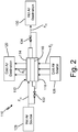
- FIG. 2 is a simplified schematic view of ECS pack 110 with heat exchanger assembly 112 (including first heat exchanger 114, second heat exchanger 116, and third heat exchanger 118), cold air destination 122, cold air source 126, hot air source 128, hot air destination 130, first valve 132, second valve 134, flow F C of cold air, and flow F H of hot air.
- ECS pack 110, heat exchanger assembly 112, first heat exchanger 114, second heat exchanger 116, and third heat exchanger 118 shown in FIG. 2 correspond to the same or similar elements as ECS pack 10, heat exchanger assembly 12, first heat exchanger 14, second heat exchanger 16, and third heat exchanger 18, respectively, shown in and discussed with respect to FIG. 1 .
- heat exchanger assembly 112 can be a pre-cooler heat exchanger.
- first heat exchanger 114, second heat exchanger 116, and third heat exchanger 118 each include an inlet, an outlet, and a cold air passage.
- the cold air passages of the first, second, and third heat exchangers 114, 116, and 118 can be in series flow communication with each other.
- first heat exchanger 114, second heat exchanger 116, and third heat exchanger 118 can be referred to as heat exchanger passes, hot passes, or (hot) cores.
- first, second, and third heat exchangers 114, 116, and 118 can be a plurality of heat exchanger cores.
- Cold air destination 122 is a destination for flow F C of cold air.
- cold air destination 122 can be ACM 22 (shown in FIG. 1 ).
- Cold air source 126 is a source of flow F C of cold air.
- cold air source 126 can be inlet plenum 26 (shown in FIG. 1 ).
- cold air source 126 can be a source of RAM air from the aircraft.
- Hot air source 128 is a source of flow F H of hot air.
- hot air source 128 can be referred to as a system inlet of heat exchanger system 112.
- Hot air destination 130 is a destination of flow F H of hot air.
- hot air destination 130 can be referred to as a system outlet of heat exchanger system 112.
- First valve 132 and second valve 134 are devices configured to regulate (e.g., allow, prevent, limit) a flow of a fluid such as air.
- first valve 132 and second valve 134 can be referred to as a valve array.
- Flow F C of cold air and flow F H of hot air are streams of airflow.
- flow F C is a flow of cold air
- flow F H is a flow of hot air (i.e., flow F C of cold air has a lesser amount of thermal energy than flow F H of hot air).
- Heat exchanger assembly 112 is configured in a cross-flow arrangement such that the direction of flow F C cold air through heat exchanger assembly 12 is orthogonal to flow F H of hot air through heat exchanger assembly 112.
- Cold air destination 122 is fluidly connected to and located downstream (e.g., a downstream direction of flow F C of cold air that is shown as down to up in FIG. 2 ) from first heat exchanger 114.
- Cold air source 126 is fluidly connected to and located upstream (e.g., an upstream direction of flow F C of cold air that is shown as up to down in FIG. 2 ) from third heat exchanger 118.
- Hot air source 128 is fluidly connected to and located upstream (e.g., an upstream direction of flow F H of hot air that is shown as right to left in FIG. 2 ) from first heat exchanger 114.
- Hot air source 128 is also fluidly connected to and located upstream from second and third heat exchangers 116 and 118, with first valve 132 being connected in-line between hot air source 128 and second and third heat exchangers 116 and 118.
- Hot air destination 130 is fluidly connected to and located downstream (e.g., a downstream direction of flow F H of hot air that is shown as left to right in FIG. 2 ) from first heat exchanger 114.
- Hot air destination 130 is also connected to and located downstream from first and second heat exchangers 114 and 116, with second valve 134 being connected in-line between hot air destination 130 and first and second heat exchangers 114 and 116.
- First valve 132 is fluidly connected in-line between hot air source 128 and second and third heat exchangers 116 and 118.
- first valve 132 is shown as a single valve.
- Second valve 134 is fluidly connected in-line between hot air destination 130 and first and second heat exchangers 114 and 116.
- Flow F C of cold air flows from cold air source 126 into heat exchanger assembly 112, through passages formed by cold fins in each of first, second, and third heat exchangers 114, 116, and 118, and flows out of heat exchanger assembly 112 to cold air destination 120.
- Flow F H of hot air flows from hot air source 128, through heat exchanger assembly 112, and to hot air destination 130.
- first and second valves 132 and 134 are configured to occupy either a first open state (e.g., mode) or a second closed state (e.g., mode).
- first and second valves 132 and 134 occupy the first open state
- heat exchanger assembly 112 is configured as simple cross-flow heat exchanger such that first, second, and third heat exchangers 114, 116, and 118 are in parallel flow alignment with each other.
- valve array i.e., first and second valves 132 and 134 fluidly connects the system inlet (i.e., hot air source 128) to the system outlet (i.e., hot air destination 130) via parallel flow through all of the plurality of heat exchanger cores (i.e., first, second, and third heat exchangers 114, 116, and 118).
- first closed position of first and second valves 132 and 134 causes flow F H of hot air to pass from the first outlet of first heat exchanger 114 to the second outlet of second heat exchanger 116, to pass through second heat exchanger 116, to pass out of the second inlet of second heat exchanger 116 to the third inlet of third heat exchanger 118, to pass through third heat exchanger 118, to pass out of the third outlet of the third heat exchanger 118, and to hot air destination 130.
- heat exchanger assembly 112 is configured as a triple pass cross-flow heat exchanger such that first, second, and third heat exchangers 114, 116, and 118 are configured in a series flow alignment.
- the valve array i.e., first and second valves 132 and 134 fluidly connects the system inlet (i.e., hot air source 128) to the system outlet (i.e., hot air destination 130) via serial flow through each of the plurality of heat exchanger cores (i.e., first, second, and third heat exchangers 114, 116, and 118).
- first and second valves 132 and 134 causes flow F H of hot air from hot air source 128 to pass through each of first, second, and third heat exchangers 114, 116, and 118 in a same downstream direction (e.g., shown as left to right in FIG. 2 ) towards hot air destination 130.
- a method of regulating heat exchanger assembly 112 includes adjusting first valve 132 and second valve 134 to vary between a first closed position and a second open position. In response to the adjustment of first and second valves 132 and 134, heat exchanger assembly 112 can be varied between a single cross-flow configuration and a triple-pass cross-flow configuration.
- adjusting first valve 132 and second valve 134 to occupy the first closed position comprises routing flow F H of hot air to pass from the first outlet of first heat exchanger 114 to the second outlet of second heat exchanger 116, to pass through second heat exchanger 116, to pass out of the second inlet of second heat exchanger 116 to the third inlet of third heat exchanger 118, to pass through third heat exchanger 118, to pass out of the third outlet of the third heat exchanger 118, and to hot air destination 130.
- adjusting first valve 132 and second valve 134 to occupy the second open position comprises routing flow F H of hot air hot air source 128 to pass through each of first, second, and third heat exchangers 114, 116, and 118 in the same downstream direction towards hot air destination 130.
- heat exchanger systems 12/112 allow for operability and sizing flexibility of ECS packs 10/110. Instead of regulating flow only with a flow control valve and throwing away pressure when the pressure is not needed, heat exchanger systems 12/112 can be configured into a less effective low pressure drop (simple cross flow) configuration or a higher effective high pressure drop (3 pass cross flow) configuration.
- the overall benefits of heat exchanger systems 12/112 with first and second valves 132 and 134 are lower fuel burn (e.g., of the aircraft) and/or a reduction in pressure drop across ECS packs 10/110.
- An environmental control system includes a cross-flow heat exchanger, a first valve, and a second valve.
- the heat exchanger includes three cores each with their own respective inlet, outlet, and cold air passage.
- the first inlet is fluidly connected with a hot air source.
- the second outlet is fluidly connected to the first outlet.
- the third inlet is fluidly connected to the second inlet and to a hot air destination.
- the first valve is fluidly connected with the hot air source, the second inlet, and the third inlet.
- the first valve is positioned in-line between the hot air source and the second and third inlets.
- the second valve is fluidly connected to the hot air destination, to the first outlet, and to the second outlet.
- the second valve is positioned in-line between the hot air destination and the first and second outlets.
- the environmental control system of the preceding paragraph can optionally include, additionally and/or alternatively, any one or more of the following features, configurations and/or additional components.
- Each of the first and second valves can be configured to occupy either a first open state or a second closed state.
- the heat exchanger assembly can configured as simple cross-flow heat exchanger assembly such that the first, second, and/or third cores can be in parallel flow alignment with each other.
- the first open state of the first and second valves can cause the flow of hot air from the hot air source to pass through each of the first, second, and/or third cores in a same downstream direction towards the hot air destination.
- the second closed state of the first and second valves can cause the flow of hot air to pass from the first outlet to the second outlet, to pass through the second core, to pass out of the second inlet to the third inlet, to pass through the third core, to pass out of the third outlet and to the hot air destination.
- the heat exchanger assembly can be configured as a triple pass cross-flow heat exchanger assembly such that the first, second, and/or third cores can be configured in a series flow alignment.
- a method of regulating a heat exchanger assembly of an environmental control system includes adjusting a first valve and a second valve to vary between a first open state and a second state position.
- the first open state comprises both of the first and second valves occupying an open position and the second closed state comprises both of the first and second valves occupying a closed position.
- a single cross-flow configuration and a triple-pass cross-flow configuration are then varied between in response to the adjustment of the first and second valves.
- the method of the preceding paragraph can optionally include, additionally and/or alternatively, any one or more of the following steps, features, configurations and/or additional components.
- the first valve can be fluidly connected with the hot air source, the second inlet, and/or the third inlet, wherein the first valve can be positioned in-line between the hot air source and the second and third inlets, and/or the second valve can be fluidly connected to the hot air destination, to the first outlet, and/or to the second outlet, wherein the second valve can be positioned in-line between the hot air destination and the first and second outlets.
- a flow of hot air can be routed from the hot air source to pass through each of the first, second, and/or third cores in a same downstream direction towards the hot air destination.
- a flow of hot air can be routed to pass from the first outlet to the second outlet, to pass through the second core, to pass out of the second inlet to the third inlet, to pass through the third core, to pass out of the third outlet and to the hot air destination.
- a heat exchanger system includes a system inlet, a system outlet, a plurality of heat exchanger cores, and a valve array.
- the system inlet is disposed to receive a first fluid into the heat exchanger system.
- the system outlet is disposed to expel the first fluid from the heat exchanger system.
- the plurality of heat exchanger cores is disposed between the system inlet and the system outlet.
- the valve array is operable in multiple modes including a first mode and a second mode. The first mode being where the valve array fluidly connects the system inlet to the system outlet via parallel flow through all of the plurality of heat exchanger cores.
- the second mode being where the valve array fluidly connects the system inlet to the system outlet via serial flow through each of the plurality of heat exchanger cores.
- the heat exchanger system of the preceding paragraph can optionally include, additionally and/or alternatively, any one or more of the following features, configurations and/or additional components.
- the first mode can cause the first fluid from the system inlet to pass through each of the plurality of heat exchanger cores in a same downstream direction towards the system outlet.
- the plurality of the heat exchanger cores can comprise a first, a second, and/or a third heat exchanger cores.
- the second mode can cause the first fluid from the system inlet to pass to an inlet of a first heat exchanger core, to pass through the first heat exchanger core, to pass out of an outlet of the first heat exchanger core, to pass into an outlet of the second heat exchanger core, to pass through the second heat exchanger core, to pass from an inlet of the second heat exchanger core to an inlet of the third heat exchanger core, to pass through the third heat exchanger core, to pass out of an outlet of the third heat exchanger core, and/or to pass to the system outlet.
- a first valve fluidly can be connected with the system inlet, an inlet of the second heat exchanger core, and/or an inlet of the third heat exchanger core, wherein the first valve can be positioned in-line between the system inlet and/or the inlets of the second and third heat exchangers, and a second valve fluidly can be connected to the system outlet, to an outlet of the first heat exchanger core, and/or to an outlet of the second heat exchanger core, wherein the second valve can be positioned in-line between the system outlet and/or the outlets of the first and second heat exchanger cores.
- the heat exchanger assembly can be configured as a triple-pass cross-flow heat exchanger assembly.
Landscapes
- Engineering & Computer Science (AREA)
- Physics & Mathematics (AREA)
- Thermal Sciences (AREA)
- Mechanical Engineering (AREA)
- General Engineering & Computer Science (AREA)
- Health & Medical Sciences (AREA)
- General Health & Medical Sciences (AREA)
- Pulmonology (AREA)
- Aviation & Aerospace Engineering (AREA)
- Heat-Exchange Devices With Radiators And Conduit Assemblies (AREA)
- Air-Conditioning For Vehicles (AREA)
Abstract
Description
- The present disclosure relates generally to an environmental control system ("ECS") and more particularly to management of air flow into a heat exchanger assembly of an ECS.
- The ECS aboard an aircraft provides conditioned air to an aircraft cabin. Conditioned air is air at a desired temperature, pressure, and humidity for aircraft passenger comfort. Compressing ambient air at flight altitude heats the resulting pressurized air sufficiently that it must be cooled, even if the ambient air temperature is very low. Thus, under most conditions, heat must be removed from air by the ECS before the air is delivered to the aircraft cabin. As heat is removed from the air, it is dissipated by the ECS into a separate stream of air that flows into the ECS, across heat exchangers in the ECS, and out of the aircraft, carrying the excess heat with it. Under conditions where the aircraft is moving fast enough, the pressure of air ramming into the aircraft is sufficient to move enough air through the ECS and over the heat exchangers to remove the excess heat.
- In existing ECS's, a bleed flow control valve is typically fully open at a particular sizing design point. The bleed flow control valve then throttles down for other operating conditions where the demand for pressure/flow is less. This throttling down of the bleed flow control valve essentially results in throwing away pressure within the environmental control system.
- An environmental control system includes a cross-flow heat exchanger, a first valve, and a second valve. The heat exchanger includes three cores each with their own respective inlet, outlet, and cold air passage. The first inlet is fluidly connected with a hot air source. The second outlet is fluidly connected to the first outlet. The third inlet is fluidly connected to the second inlet and to a hot air destination. The first valve is fluidly connected with the hot air source, the second inlet, and the third inlet. The first valve is positioned in-line between the hot air source and the second and third inlets. The second valve is fluidly connected to the hot air destination, to the first outlet, and to the second outlet. The second valve is positioned in-line between the hot air destination and the first and second outlets.
- A method of regulating a heat exchanger assembly of an environmental control system includes adjusting a first valve and a second valve to vary between a first open state and a second state position. The first open state comprises both of the first and second valves occupying an open position and the second closed state comprises both of the first and second valves occupying a closed position. A single cross-flow configuration and a triple-pass cross-flow configuration are then varied between in response to the adjustment of the first and second valves.
- A heat exchanger system includes a system inlet, a system outlet, a plurality of heat exchanger cores, and a valve array. The system inlet is disposed to receive a first fluid into the heat exchanger system. The system outlet is disposed to expel the first fluid from the heat exchanger system. The plurality of heat exchanger cores is disposed between the system inlet and the system outlet. The valve array is operable in multiple modes including a first mode and a second mode. The first mode being where the valve array fluidly connects the system inlet to the system outlet via parallel flow through all of the plurality of heat exchanger cores. The second mode being where the valve array fluidly connects the system inlet to the system outlet via serial flow through each of the plurality of heat exchanger cores.
- The present summary is provided only by way of example, and not limitation. Other aspects of the present disclosure will be appreciated in view of the entirety of the present disclosure, including the entire text, claims, and accompanying figures.
-
-
FIG. 1 is a perspective view of an ECS pack with a heat exchanger assembly. -
FIG. 2 is a simplified schematic view of the heat exchanger with upstream and downstream vales. - While the above-identified figures set forth one or more embodiments of the present disclosure, other embodiments are also contemplated, as noted in the discussion. In all cases, this disclosure presents embodiments by way of representation and not limitation. It should be understood that numerous other modifications and embodiments can be devised by those skilled in the art, which fall within the scope and spirit of the principles of the disclosure. The figures may not be drawn to scale, and applications and embodiments of the present disclosure may include features and components not specifically shown in the drawings.
- In the present disclosure, valves are installed upstream and downstream of the heat exchanger cores that regulate whether the heat exchanger acts as a simple cross flow (all three inlets and three outlets open) or as a three-pass cross flow. In this way, the heat exchanger assembly can be configured into a less effective low pressure drop (simple cross flow) configuration or a higher effective high pressure drop (three-pass cross flow) configuration providing the benefits of lower fuel bum and/or volume reduction.
-
FIG. 1 is a perspective view ofECS pack 10 and shows heat exchanger assembly 12 (withfirst heat exchanger 14,second heat exchanger 16, and third heat exchanger 18), FIDH 20 (fan inlet diffuser housing), ACM 22 (air cycle machine),power turbine 24, andinlet plenum 26. - ECS
pack 10 is an environmental control system. In this non-limiting embodiment, ECSpack 10 is an environmental control system for an aircraft.Heat exchanger assembly 12 is an assembly of three heat exchanger units.First heat exchanger 14,second heat exchanger 16, andthird heat exchanger 18 are heat exchangers each with a plurality of fins for transferring thermal energy between working fluids. In this example,first heat exchanger 14 can be a chiller heat exchanger,second heat exchanger 16 can be a fresh air heat exchanger, andthird heat exchanger 18 can be a bleed air heat exchanger. FIDH 20 is a fan inlet diffuser housing. ACM 22 is an air cycle machine.Power turbine 24 is a rotary device including a component configured to create power by rotating in response to a fluid flowing throughpower turbine 24.Inlet plenum 26 is an inlet housing or conduit. - ECS
pack 10 can be mounted within a portion of an aircraft. ECSpack 10 can be fluidly connected to numerous fluid sources such as an engine, an auxiliary power unit, a source of ambient air, a cabin, a cockpit, and/or a source of ram air of the aircraft.Heat exchanger assembly 12 is mounted within a portion ofECS pack 10.First heat exchanger 14 is disposed adjacent to and in contact withsecond heat exchanger 16.First heat exchanger 14 is fluidly connected toinlet plenum 26 via a cold circuit ofheat exchanger assembly 12 that passes through each offirst heat exchanger 14,second heat exchanger 16, and third heat exchanger 18 (as will be discussed with respect toFIG. 2 ). -
Second heat exchanger 16 is disposed adjacent to and in contact withfirst heat exchanger 14 andthird heat exchanger 18.Second heat exchanger 16 can be fluidly connected to a fresh air compressor (not shown) and to a condenser re-heater (not shown) ofECS pack 10.Third heat exchanger 18 is disposed adjacent to and in contact withsecond heat exchanger 16 and FIDH 20.Third heat exchanger 18 can be fluidly connected to a bleed outflow heat exchanger (not shown) and tofirst heat exchanger 14 ofECS pack 10. - FIDH 20 is mounted to a side of
third heat exchanger 18 and to a turbo fan (not shown) ofECS pack 10. FIDH 20 can be fluidly connected to the cold ram air circuit that passes throughheat exchanger assembly 12. In other non-limiting embodiments, FIDH 20 can be replaced with another component or removed all together fromECS pack 10.ACM 22 is physically and fluidly connected topower turbine 24.Power turbine 24 is mounted to a portion ofACM 22 and is fluidly connected toACM 22 and toinlet plenum 26.Inlet plenum 26 is mounted tofirst heat exchanger 14.Inlet plenum 26 is fluidly connected tofirst heat exchanger 14, to a source of ram air, and topower turbine 24. -
ECS pack 10 controls and manages the transfer of thermal energy and pressures among the different sources of air throughout the aircraft. Heat exchanger assembly 12 (withfirst heat exchanger 14,second heat exchanger 16, and third heat exchanger 18) functions to cool the air flowing through each offirst heat exchanger 14,second heat exchanger 16, andthird heat exchanger 18. As will be discussed with respect toFIG. 2 ,heat exchanger assembly 12 includes three independent hot circuits that are in cross flow communication with a single (cold) ram air circuit. -
FIDH 20 receives and transfers air away from the cold ram air circuit ofheat exchanger assembly 12.ACM 22 functions as an air conditioning pack to change to the pressure, temperature, and/or humidity of air passing throughACM 22.Inlet plenum 26 receives cooling air from two separate sources and transfers that air intoheat exchanger assembly 12. The two sources can be ambient ram air and exhaust air frompower turbine 24. - An additional example of an environmental control system can be found in the following co-pending application: United States Patent Application Serial No.
15/879,192 filed on January 24, 2018 -
FIG. 2 is a simplified schematic view ofECS pack 110 with heat exchanger assembly 112 (includingfirst heat exchanger 114,second heat exchanger 116, and third heat exchanger 118), cold air destination 122,cold air source 126,hot air source 128,hot air destination 130,first valve 132,second valve 134, flow FC of cold air, and flow FH of hot air.ECS pack 110,heat exchanger assembly 112,first heat exchanger 114,second heat exchanger 116, andthird heat exchanger 118 shown inFIG. 2 correspond to the same or similar elements asECS pack 10,heat exchanger assembly 12,first heat exchanger 14,second heat exchanger 16, andthird heat exchanger 18, respectively, shown in and discussed with respect toFIG. 1 . - In this non-limiting embodiment,
heat exchanger assembly 112 can be a pre-cooler heat exchanger. In this example,first heat exchanger 114,second heat exchanger 116, andthird heat exchanger 118 each include an inlet, an outlet, and a cold air passage. For example, the cold air passages of the first, second, andthird heat exchangers first heat exchanger 114,second heat exchanger 116, andthird heat exchanger 118 can be referred to as heat exchanger passes, hot passes, or (hot) cores. In one non-limiting embodiment, first, second, andthird heat exchangers - Cold air destination 122 is a destination for flow FC of cold air. In one example, cold air destination 122 can be ACM 22 (shown in
FIG. 1 ).Cold air source 126 is a source of flow FC of cold air. In one example,cold air source 126 can be inlet plenum 26 (shown inFIG. 1 ). In another example,cold air source 126 can be a source of RAM air from the aircraft.Hot air source 128 is a source of flow FH of hot air. In one example,hot air source 128 can be referred to as a system inlet ofheat exchanger system 112.Hot air destination 130 is a destination of flow FH of hot air. In one example,hot air destination 130 can be referred to as a system outlet ofheat exchanger system 112. -
First valve 132 andsecond valve 134 are devices configured to regulate (e.g., allow, prevent, limit) a flow of a fluid such as air. In one example,first valve 132 andsecond valve 134 can be referred to as a valve array. Flow FC of cold air and flow FH of hot air are streams of airflow. In this example, flow FC is a flow of cold air and flow FH is a flow of hot air (i.e., flow FC of cold air has a lesser amount of thermal energy than flow FH of hot air). -
Heat exchanger assembly 112 is configured in a cross-flow arrangement such that the direction of flow FC cold air throughheat exchanger assembly 12 is orthogonal to flow FH of hot air throughheat exchanger assembly 112. Cold air destination 122 is fluidly connected to and located downstream (e.g., a downstream direction of flow FC of cold air that is shown as down to up inFIG. 2 ) fromfirst heat exchanger 114.Cold air source 126 is fluidly connected to and located upstream (e.g., an upstream direction of flow FC of cold air that is shown as up to down inFIG. 2 ) fromthird heat exchanger 118. -
Hot air source 128 is fluidly connected to and located upstream (e.g., an upstream direction of flow FH of hot air that is shown as right to left inFIG. 2 ) fromfirst heat exchanger 114.Hot air source 128 is also fluidly connected to and located upstream from second andthird heat exchangers first valve 132 being connected in-line betweenhot air source 128 and second andthird heat exchangers Hot air destination 130 is fluidly connected to and located downstream (e.g., a downstream direction of flow FH of hot air that is shown as left to right inFIG. 2 ) fromfirst heat exchanger 114.Hot air destination 130 is also connected to and located downstream from first andsecond heat exchangers second valve 134 being connected in-line betweenhot air destination 130 and first andsecond heat exchangers -
First valve 132 is fluidly connected in-line betweenhot air source 128 and second andthird heat exchangers first valve 132 is shown as a single valve.Second valve 134 is fluidly connected in-line betweenhot air destination 130 and first andsecond heat exchangers cold air source 126 intoheat exchanger assembly 112, through passages formed by cold fins in each of first, second, andthird heat exchangers heat exchanger assembly 112 tocold air destination 120. Flow FH of hot air flows fromhot air source 128, throughheat exchanger assembly 112, and tohot air destination 130. - Each of first and
second valves second valves heat exchanger assembly 112 is configured as simple cross-flow heat exchanger such that first, second, andthird heat exchangers second valves 132 and 134) fluidly connects the system inlet (i.e., hot air source 128) to the system outlet (i.e., hot air destination 130) via parallel flow through all of the plurality of heat exchanger cores (i.e., first, second, andthird heat exchangers second valves first heat exchanger 114 to the second outlet ofsecond heat exchanger 116, to pass throughsecond heat exchanger 116, to pass out of the second inlet ofsecond heat exchanger 116 to the third inlet ofthird heat exchanger 118, to pass throughthird heat exchanger 118, to pass out of the third outlet of thethird heat exchanger 118, and tohot air destination 130. - In the second close state,
heat exchanger assembly 112 is configured as a triple pass cross-flow heat exchanger such that first, second, andthird heat exchangers second valves 132 and 134) fluidly connects the system inlet (i.e., hot air source 128) to the system outlet (i.e., hot air destination 130) via serial flow through each of the plurality of heat exchanger cores (i.e., first, second, andthird heat exchangers second valves hot air source 128 to pass through each of first, second, andthird heat exchangers FIG. 2 ) towardshot air destination 130. - In one non-limiting embodiment, a method of regulating
heat exchanger assembly 112 includes adjustingfirst valve 132 andsecond valve 134 to vary between a first closed position and a second open position. In response to the adjustment of first andsecond valves heat exchanger assembly 112 can be varied between a single cross-flow configuration and a triple-pass cross-flow configuration. For example, adjustingfirst valve 132 andsecond valve 134 to occupy the first closed position comprises routing flow FH of hot air to pass from the first outlet offirst heat exchanger 114 to the second outlet ofsecond heat exchanger 116, to pass throughsecond heat exchanger 116, to pass out of the second inlet ofsecond heat exchanger 116 to the third inlet ofthird heat exchanger 118, to pass throughthird heat exchanger 118, to pass out of the third outlet of thethird heat exchanger 118, and tohot air destination 130. - In another example, adjusting
first valve 132 andsecond valve 134 to occupy the second open position comprises routing flow FH of hot airhot air source 128 to pass through each of first, second, andthird heat exchangers hot air destination 130. - The adaptive features of
heat exchanger systems 12/112 allow for operability and sizing flexibility of ECS packs 10/110. Instead of regulating flow only with a flow control valve and throwing away pressure when the pressure is not needed,heat exchanger systems 12/112 can be configured into a less effective low pressure drop (simple cross flow) configuration or a higher effective high pressure drop (3 pass cross flow) configuration. The overall benefits ofheat exchanger systems 12/112 with first andsecond valves - An environmental control system includes a cross-flow heat exchanger, a first valve, and a second valve. The heat exchanger includes three cores each with their own respective inlet, outlet, and cold air passage. The first inlet is fluidly connected with a hot air source. The second outlet is fluidly connected to the first outlet. The third inlet is fluidly connected to the second inlet and to a hot air destination. The first valve is fluidly connected with the hot air source, the second inlet, and the third inlet. The first valve is positioned in-line between the hot air source and the second and third inlets. The second valve is fluidly connected to the hot air destination, to the first outlet, and to the second outlet. The second valve is positioned in-line between the hot air destination and the first and second outlets.
- The environmental control system of the preceding paragraph can optionally include, additionally and/or alternatively, any one or more of the following features, configurations and/or additional components.
- Each of the first and second valves can be configured to occupy either a first open state or a second closed state.
- With the first and second valves occupying the first open state, the heat exchanger assembly can configured as simple cross-flow heat exchanger assembly such that the first, second, and/or third cores can be in parallel flow alignment with each other.
- The first open state of the first and second valves can cause the flow of hot air from the hot air source to pass through each of the first, second, and/or third cores in a same downstream direction towards the hot air destination.
- The second closed state of the first and second valves can cause the flow of hot air to pass from the first outlet to the second outlet, to pass through the second core, to pass out of the second inlet to the third inlet, to pass through the third core, to pass out of the third outlet and to the hot air destination.
- With the first and second valves occupying the second closed state, the heat exchanger assembly can be configured as a triple pass cross-flow heat exchanger assembly such that the first, second, and/or third cores can be configured in a series flow alignment.
- A method of regulating a heat exchanger assembly of an environmental control system includes adjusting a first valve and a second valve to vary between a first open state and a second state position. The first open state comprises both of the first and second valves occupying an open position and the second closed state comprises both of the first and second valves occupying a closed position. A single cross-flow configuration and a triple-pass cross-flow configuration are then varied between in response to the adjustment of the first and second valves.
- The method of the preceding paragraph can optionally include, additionally and/or alternatively, any one or more of the following steps, features, configurations and/or additional components.
- The first valve can be fluidly connected with the hot air source, the second inlet, and/or the third inlet, wherein the first valve can be positioned in-line between the hot air source and the second and third inlets, and/or the second valve can be fluidly connected to the hot air destination, to the first outlet, and/or to the second outlet, wherein the second valve can be positioned in-line between the hot air destination and the first and second outlets.
- A flow of hot air can be routed from the hot air source to pass through each of the first, second, and/or third cores in a same downstream direction towards the hot air destination.
- A flow of hot air can be routed to pass from the first outlet to the second outlet, to pass through the second core, to pass out of the second inlet to the third inlet, to pass through the third core, to pass out of the third outlet and to the hot air destination.
- A heat exchanger system includes a system inlet, a system outlet, a plurality of heat exchanger cores, and a valve array. The system inlet is disposed to receive a first fluid into the heat exchanger system. The system outlet is disposed to expel the first fluid from the heat exchanger system. The plurality of heat exchanger cores is disposed between the system inlet and the system outlet. The valve array is operable in multiple modes including a first mode and a second mode. The first mode being where the valve array fluidly connects the system inlet to the system outlet via parallel flow through all of the plurality of heat exchanger cores. The second mode being where the valve array fluidly connects the system inlet to the system outlet via serial flow through each of the plurality of heat exchanger cores.
- The heat exchanger system of the preceding paragraph can optionally include, additionally and/or alternatively, any one or more of the following features, configurations and/or additional components.
- The first mode can cause the first fluid from the system inlet to pass through each of the plurality of heat exchanger cores in a same downstream direction towards the system outlet.
- The plurality of the heat exchanger cores can comprise a first, a second, and/or a third heat exchanger cores.
- The second mode can cause the first fluid from the system inlet to pass to an inlet of a first heat exchanger core, to pass through the first heat exchanger core, to pass out of an outlet of the first heat exchanger core, to pass into an outlet of the second heat exchanger core, to pass through the second heat exchanger core, to pass from an inlet of the second heat exchanger core to an inlet of the third heat exchanger core, to pass through the third heat exchanger core, to pass out of an outlet of the third heat exchanger core, and/or to pass to the system outlet.
- A first valve fluidly can be connected with the system inlet, an inlet of the second heat exchanger core, and/or an inlet of the third heat exchanger core, wherein the first valve can be positioned in-line between the system inlet and/or the inlets of the second and third heat exchangers, and a second valve fluidly can be connected to the system outlet, to an outlet of the first heat exchanger core, and/or to an outlet of the second heat exchanger core, wherein the second valve can be positioned in-line between the system outlet and/or the outlets of the first and second heat exchanger cores.
- With the valve array occupying the second mode, the heat exchanger assembly can be configured as a triple-pass cross-flow heat exchanger assembly.
- While the invention has been described with reference to an exemplary embodiment(s), it will be understood by those skilled in the art that various changes may be made and equivalents may be substituted for elements thereof without departing from the scope of the invention. In addition, many modifications may be made to adapt a particular situation or material to the teachings of the invention without departing from the essential scope thereof. Therefore, it is intended that the invention not be limited to the particular embodiment(s) disclosed, but that the invention will include all embodiments falling within the scope of the appended claims.
Claims (10)
- An environmental control system (10) comprising:a heat exchanger assembly (12) comprising:a first core (114) comprising:a first inlet;a first outlet, wherein the first inlet is fluidly connected with a hot air source; anda first cold air passage;a second core (116) comprising:a second inlet;a second outlet, wherein the second outlet is fluidly connected to the first outlet; anda second cold air passage;a third core (118) comprising:a third inlet;a third outlet, wherein the third inlet is fluidly connected to the second inlet, wherein the third outlet is fluidly connected to a hot air destination; anda third cold air passage in series flow communication with the first and second air passages, wherein the heat exchanger assembly is configured in a cross-flow arrangement such that a direction of a cold air flow through the heat exchanger assembly is orthogonal to a flow of hot air through the heat exchanger assembly;a first valve (132) fluidly connected with the hot air source, the second inlet, and the third inlet, wherein the first valve is positioned in-line between the hot air source and the second and third inlets; anda second valve (134) fluidly connected to the hot air destination, to the first outlet, and to the second outlet, wherein the second valve is positioned in-line between the hot air destination and the first and second outlets.
- The environmental control system of claim 1, further comprising wherein the each of the first and second valves are configured to occupy either a first open state or a second closed state.
- The environmental control system of claim 2, wherein when the first and second valves occupy the first open state, the heat exchanger assembly is configured as simple cross-flow heat exchanger assembly such that the first, second, and third cores are in parallel flow alignment with each other.
- The environmental control system of claim 3, wherein the first open state of the first and second valves causes the flow of hot air from the hot air source to pass through each of the first, second, and third cores in a same downstream direction towards the hot air destination.
- The environmental control system of claim 2, wherein the second closed state of the first and second valves causes the flow of hot air to pass from the first outlet to the second outlet, to pass through the second core, to pass out of the second inlet to the third inlet, to pass through the third core, to pass out of the third outlet and to the hot air destination.
- The environmental control system of claim 5, wherein when the first and second valves occupy the second closed state, the heat exchanger assembly is configured as a triple pass cross-flow heat exchanger assembly such that the first, second, and third cores are configured in a series flow alignment.
- A method of regulating a heat exchanger assembly of an environmental control system, the method comprising:adjusting a first valve (132) and a second valve (134) to vary between a first open state and a second closed state, wherein the first open state comprises both of the first and second valves occupying an open position, wherein the second closed state comprises both of the first and second valves occupying a closed position, wherein the heat exchanger assembly comprises:a first core (114) comprising:a first inlet;a first outlet, wherein the first inlet is fluidly connected with a hot air source; anda first cold air passage;a second core (116) comprising:a second inlet;a second outlet, wherein the second outlet is fluidly connected to the first outlet; anda second cold air passage;a third core (118) comprising:a third inlet;a third outlet, wherein the third inlet is fluidly connected to the second inlet, wherein the third outlet is fluidly connected to a hot air destination; anda third cold air passage in series flow communication with the first and second cold air passages, wherein the heat exchanger assembly is configured in a cross-flow arrangement such that a direction of a cold air flow through the heat exchanger assembly is orthogonal to a flow of hot air through the heat exchanger assembly; andvarying between a single cross-flow configuration and a triple-pass cross-flow configuration in response to the adjustment of the first and second valves.
- The method of claim 7, wherein:the first valve is fluidly connected with the hot air source, the second inlet, and the third inlet, wherein the first valve is positioned in-line between the hot air source and the second and third inlets; andthe second valve is fluidly connected to the hot air destination, to the first outlet, and to the second outlet, wherein the second valve is positioned in-line between the hot air destination and the first and second outlets.
- The method of claim 8, wherein adjusting the first valve and the second valve to occupy the first open state comprises routing a flow of hot air from the hot air source to pass through each of the first, second, and third cores in a same downstream direction towards the hot air destination.
- The method of claim 8, wherein adjusting the first valve and the second valve to occupy the second closed state comprises routing a flow of hot air to pass from the first outlet to the second outlet, to pass through the second core, to pass out of the second inlet to the third inlet, to pass through the third core, to pass out of the third outlet and to the hot air destination.
Applications Claiming Priority (1)
| Application Number | Priority Date | Filing Date | Title |
|---|---|---|---|
| US16/458,732 US11046441B2 (en) | 2019-07-01 | 2019-07-01 | Adaptive plate-fin heat exchanger |
Publications (2)
| Publication Number | Publication Date |
|---|---|
| EP3760544A1 true EP3760544A1 (en) | 2021-01-06 |
| EP3760544B1 EP3760544B1 (en) | 2025-10-29 |
Family
ID=68840982
Family Applications (1)
| Application Number | Title | Priority Date | Filing Date |
|---|---|---|---|
| EP19214569.6A Active EP3760544B1 (en) | 2019-07-01 | 2019-12-09 | Adaptive plate-fin heat exchanger |
Country Status (2)
| Country | Link |
|---|---|
| US (1) | US11046441B2 (en) |
| EP (1) | EP3760544B1 (en) |
Families Citing this family (1)
| Publication number | Priority date | Publication date | Assignee | Title |
|---|---|---|---|---|
| US20260028126A1 (en) * | 2024-07-29 | 2026-01-29 | Hamilton Sundstrand Corporation | Additively manufactured heat exchanger and diffuser pipe coupled to a compressor stage |
Citations (4)
| Publication number | Priority date | Publication date | Assignee | Title |
|---|---|---|---|---|
| JP2003240375A (en) * | 2002-02-20 | 2003-08-27 | Sumitomo Precision Prod Co Ltd | Air cycle type air conditioner |
| EP3219619A1 (en) * | 2016-03-16 | 2017-09-20 | Hamilton Sundstrand Corporation | Pack-and-a-half architecture for environmental control systems |
| EP3421364A1 (en) * | 2017-06-28 | 2019-01-02 | Hamilton Sundstrand Corporation | Three wheel and simple cycle aircraft environmental control system |
| EP3517875A1 (en) * | 2018-01-24 | 2019-07-31 | Hamilton Sundstrand Corporation | Heat exchanger with external plenum |
Family Cites Families (14)
| Publication number | Priority date | Publication date | Assignee | Title |
|---|---|---|---|---|
| US3990504A (en) * | 1975-09-29 | 1976-11-09 | International Harvester Company | Two stage operation for radiator |
| US4168030A (en) * | 1976-10-22 | 1979-09-18 | Timmerman Robert W | Waste heat utilization system |
| JP2875309B2 (en) * | 1989-12-01 | 1999-03-31 | 株式会社日立製作所 | Air conditioner, heat exchanger used in the device, and control method for the device |
| US7726388B2 (en) * | 2004-08-25 | 2010-06-01 | Komatsu Ltd. | Heat exchanger |
| US8079407B2 (en) | 2006-11-09 | 2011-12-20 | Honeywell International Inc. | Integrated heat exchangers for ECS and OBIGGS applications |
| US20110056668A1 (en) * | 2008-04-29 | 2011-03-10 | Carrier Corporation | Modular heat exchanger |
| US9745069B2 (en) | 2013-01-21 | 2017-08-29 | Hamilton Sundstrand Corporation | Air-liquid heat exchanger assembly having a bypass valve |
| US10533784B2 (en) * | 2016-03-16 | 2020-01-14 | Hamilton Sundstrand Corporation | Pack-and-A-half architecture for environmental control systems |
| US9505484B1 (en) * | 2016-04-11 | 2016-11-29 | Nasser M. Al-Sabah | Modular aircraft system |
| US20190291863A1 (en) * | 2016-05-18 | 2019-09-26 | A^3 By Airbus Llc | Vertical takeoff and landing aircraft with tilted-wing configurations |
| US10618647B2 (en) * | 2016-07-01 | 2020-04-14 | Textron Innovations Inc. | Mission configurable aircraft having VTOL and biplane orientations |
| EP3566431A4 (en) * | 2017-02-24 | 2020-03-18 | SZ DJI Technology Co., Ltd. | MULTIPLE CARDAN SET |
| EP3601042B1 (en) * | 2017-03-22 | 2024-03-13 | Aurora Flight Sciences Corporation | Multi-architecture modular unmanned aerial system |
| US10787255B2 (en) * | 2018-11-30 | 2020-09-29 | Sky Canoe Inc. | Aerial vehicle with enhanced pitch control and interchangeable components |
-
2019
- 2019-07-01 US US16/458,732 patent/US11046441B2/en active Active
- 2019-12-09 EP EP19214569.6A patent/EP3760544B1/en active Active
Patent Citations (4)
| Publication number | Priority date | Publication date | Assignee | Title |
|---|---|---|---|---|
| JP2003240375A (en) * | 2002-02-20 | 2003-08-27 | Sumitomo Precision Prod Co Ltd | Air cycle type air conditioner |
| EP3219619A1 (en) * | 2016-03-16 | 2017-09-20 | Hamilton Sundstrand Corporation | Pack-and-a-half architecture for environmental control systems |
| EP3421364A1 (en) * | 2017-06-28 | 2019-01-02 | Hamilton Sundstrand Corporation | Three wheel and simple cycle aircraft environmental control system |
| EP3517875A1 (en) * | 2018-01-24 | 2019-07-31 | Hamilton Sundstrand Corporation | Heat exchanger with external plenum |
Also Published As
| Publication number | Publication date |
|---|---|
| EP3760544B1 (en) | 2025-10-29 |
| US20210001993A1 (en) | 2021-01-07 |
| US11046441B2 (en) | 2021-06-29 |
Similar Documents
| Publication | Publication Date | Title |
|---|---|---|
| US10907546B2 (en) | Cross-stream heat exchanger | |
| US6295822B1 (en) | Aircraft air-conditioning apparatus with water separators | |
| EP2944767B1 (en) | Fluid system | |
| JP4489776B2 (en) | Air cycle air conditioning with adaptive ram heat exchanger | |
| EP2711297B1 (en) | Heat exchanger systems and methods for controlling airflow cooling | |
| EP2808256B1 (en) | Heat exchanger bypass arrangement and valve assembly | |
| CN1894130B (en) | Cooling air supply system for aircraft and aircraft with the supply system | |
| US8397487B2 (en) | Environmental control system supply precooler bypass | |
| CN110920914B (en) | An aircraft integrated thermal management and regulation system | |
| US20170268810A1 (en) | Heat Exchanger with Integral Bypass Valve | |
| EP2757343B1 (en) | Sub freezing load heat exchanger bypass | |
| CN106882390B (en) | Aircraft air-entraining precooling regenerative system | |
| EP3333078B1 (en) | Air distribution system with recirculating zone trim tec | |
| US11046441B2 (en) | Adaptive plate-fin heat exchanger | |
| EP3838762A1 (en) | Air cycle machines, air cycle machine systems, and methods of controlling air flow in air cycle machines | |
| EP4269246B1 (en) | Trim module with thermoelectric cooler | |
| US20240351695A1 (en) | Suspension pylon for an aircraft engine fitted with a counterflow cooling exchanger | |
| EP3141732A1 (en) | Turbofan engine mounted precooler system | |
| US9921009B2 (en) | Dual-use ram-primary/regen hx | |
| EP4015390B1 (en) | Flexible turbine arrangement air cycle machine with adaptive heat exchanger | |
| US20250229595A1 (en) | Feature for subfreezing heat exchanger | |
| EP3222958B1 (en) | Heat exchanger with integral bypass valve |
Legal Events
| Date | Code | Title | Description |
|---|---|---|---|
| PUAI | Public reference made under article 153(3) epc to a published international application that has entered the european phase |
Free format text: ORIGINAL CODE: 0009012 |
|
| STAA | Information on the status of an ep patent application or granted ep patent |
Free format text: STATUS: THE APPLICATION HAS BEEN PUBLISHED |
|
| AK | Designated contracting states |
Kind code of ref document: A1 Designated state(s): AL AT BE BG CH CY CZ DE DK EE ES FI FR GB GR HR HU IE IS IT LI LT LU LV MC MK MT NL NO PL PT RO RS SE SI SK SM TR |
|
| AX | Request for extension of the european patent |
Extension state: BA ME |
|
| STAA | Information on the status of an ep patent application or granted ep patent |
Free format text: STATUS: REQUEST FOR EXAMINATION WAS MADE |
|
| 17P | Request for examination filed |
Effective date: 20210702 |
|
| RBV | Designated contracting states (corrected) |
Designated state(s): AL AT BE BG CH CY CZ DE DK EE ES FI FR GB GR HR HU IE IS IT LI LT LU LV MC MK MT NL NO PL PT RO RS SE SI SK SM TR |
|
| STAA | Information on the status of an ep patent application or granted ep patent |
Free format text: STATUS: EXAMINATION IS IN PROGRESS |
|
| 17Q | First examination report despatched |
Effective date: 20220215 |
|
| GRAP | Despatch of communication of intention to grant a patent |
Free format text: ORIGINAL CODE: EPIDOSNIGR1 |
|
| STAA | Information on the status of an ep patent application or granted ep patent |
Free format text: STATUS: GRANT OF PATENT IS INTENDED |
|
| INTG | Intention to grant announced |
Effective date: 20250530 |
|
| GRAS | Grant fee paid |
Free format text: ORIGINAL CODE: EPIDOSNIGR3 |
|
| GRAA | (expected) grant |
Free format text: ORIGINAL CODE: 0009210 |
|
| STAA | Information on the status of an ep patent application or granted ep patent |
Free format text: STATUS: THE PATENT HAS BEEN GRANTED |
|
| AK | Designated contracting states |
Kind code of ref document: B1 Designated state(s): AL AT BE BG CH CY CZ DE DK EE ES FI FR GB GR HR HU IE IS IT LI LT LU LV MC MK MT NL NO PL PT RO RS SE SI SK SM TR |
|
| REG | Reference to a national code |
Ref country code: CH Ref legal event code: F10 Free format text: ST27 STATUS EVENT CODE: U-0-0-F10-F00 (AS PROVIDED BY THE NATIONAL OFFICE) Effective date: 20251029 Ref country code: GB Ref legal event code: FG4D |
|
| REG | Reference to a national code |
Ref country code: IE Ref legal event code: FG4D |
|
| REG | Reference to a national code |
Ref country code: DE Ref legal event code: R096 Ref document number: 602019077345 Country of ref document: DE |
|
| PGFP | Annual fee paid to national office [announced via postgrant information from national office to epo] |
Ref country code: DE Payment date: 20251126 Year of fee payment: 7 |
|
| PGFP | Annual fee paid to national office [announced via postgrant information from national office to epo] |
Ref country code: GB Payment date: 20251120 Year of fee payment: 7 |
|
| PGFP | Annual fee paid to national office [announced via postgrant information from national office to epo] |
Ref country code: FR Payment date: 20251119 Year of fee payment: 7 |
|
| REG | Reference to a national code |
Ref country code: NL Ref legal event code: MP Effective date: 20251029 |
|
| PG25 | Lapsed in a contracting state [announced via postgrant information from national office to epo] |
Ref country code: ES Free format text: LAPSE BECAUSE OF FAILURE TO SUBMIT A TRANSLATION OF THE DESCRIPTION OR TO PAY THE FEE WITHIN THE PRESCRIBED TIME-LIMIT Effective date: 20251029 |
|
| REG | Reference to a national code |
Ref country code: LT Ref legal event code: MG9D |
|
| PG25 | Lapsed in a contracting state [announced via postgrant information from national office to epo] |
Ref country code: NO Free format text: LAPSE BECAUSE OF FAILURE TO SUBMIT A TRANSLATION OF THE DESCRIPTION OR TO PAY THE FEE WITHIN THE PRESCRIBED TIME-LIMIT Effective date: 20260129 |
|
| PG25 | Lapsed in a contracting state [announced via postgrant information from national office to epo] |
Ref country code: AT Free format text: LAPSE BECAUSE OF FAILURE TO SUBMIT A TRANSLATION OF THE DESCRIPTION OR TO PAY THE FEE WITHIN THE PRESCRIBED TIME-LIMIT Effective date: 20251029 Ref country code: FI Free format text: LAPSE BECAUSE OF FAILURE TO SUBMIT A TRANSLATION OF THE DESCRIPTION OR TO PAY THE FEE WITHIN THE PRESCRIBED TIME-LIMIT Effective date: 20251029 Ref country code: HR Free format text: LAPSE BECAUSE OF FAILURE TO SUBMIT A TRANSLATION OF THE DESCRIPTION OR TO PAY THE FEE WITHIN THE PRESCRIBED TIME-LIMIT Effective date: 20251029 |
|
| REG | Reference to a national code |
Ref country code: AT Ref legal event code: MK05 Ref document number: 1851335 Country of ref document: AT Kind code of ref document: T Effective date: 20251029 |
|
| PG25 | Lapsed in a contracting state [announced via postgrant information from national office to epo] |
Ref country code: NL Free format text: LAPSE BECAUSE OF FAILURE TO SUBMIT A TRANSLATION OF THE DESCRIPTION OR TO PAY THE FEE WITHIN THE PRESCRIBED TIME-LIMIT Effective date: 20251029 |
|
| PG25 | Lapsed in a contracting state [announced via postgrant information from national office to epo] |
Ref country code: RS Free format text: LAPSE BECAUSE OF FAILURE TO SUBMIT A TRANSLATION OF THE DESCRIPTION OR TO PAY THE FEE WITHIN THE PRESCRIBED TIME-LIMIT Effective date: 20260129 |
|
| PG25 | Lapsed in a contracting state [announced via postgrant information from national office to epo] |
Ref country code: IS Free format text: LAPSE BECAUSE OF FAILURE TO SUBMIT A TRANSLATION OF THE DESCRIPTION OR TO PAY THE FEE WITHIN THE PRESCRIBED TIME-LIMIT Effective date: 20260228 |
|
| PG25 | Lapsed in a contracting state [announced via postgrant information from national office to epo] |
Ref country code: PT Free format text: LAPSE BECAUSE OF FAILURE TO SUBMIT A TRANSLATION OF THE DESCRIPTION OR TO PAY THE FEE WITHIN THE PRESCRIBED TIME-LIMIT Effective date: 20260302 |
|
| PG25 | Lapsed in a contracting state [announced via postgrant information from national office to epo] |
Ref country code: PL Free format text: LAPSE BECAUSE OF FAILURE TO SUBMIT A TRANSLATION OF THE DESCRIPTION OR TO PAY THE FEE WITHIN THE PRESCRIBED TIME-LIMIT Effective date: 20251029 |
|
| PG25 | Lapsed in a contracting state [announced via postgrant information from national office to epo] |
Ref country code: LV Free format text: LAPSE BECAUSE OF FAILURE TO SUBMIT A TRANSLATION OF THE DESCRIPTION OR TO PAY THE FEE WITHIN THE PRESCRIBED TIME-LIMIT Effective date: 20251029 |
|
| PG25 | Lapsed in a contracting state [announced via postgrant information from national office to epo] |
Ref country code: BG Free format text: LAPSE BECAUSE OF FAILURE TO SUBMIT A TRANSLATION OF THE DESCRIPTION OR TO PAY THE FEE WITHIN THE PRESCRIBED TIME-LIMIT Effective date: 20251029 |