EP3760465A1 - Fuel tank cap locking device - Google Patents
Fuel tank cap locking device Download PDFInfo
- Publication number
- EP3760465A1 EP3760465A1 EP20178247.1A EP20178247A EP3760465A1 EP 3760465 A1 EP3760465 A1 EP 3760465A1 EP 20178247 A EP20178247 A EP 20178247A EP 3760465 A1 EP3760465 A1 EP 3760465A1
- Authority
- EP
- European Patent Office
- Prior art keywords
- unit
- engagement
- lock
- engagement unit
- fuel tank
- Prior art date
- Legal status (The legal status is an assumption and is not a legal conclusion. Google has not performed a legal analysis and makes no representation as to the accuracy of the status listed.)
- Granted
Links
Images








Classifications
-
- B—PERFORMING OPERATIONS; TRANSPORTING
- B60—VEHICLES IN GENERAL
- B60K—ARRANGEMENT OR MOUNTING OF PROPULSION UNITS OR OF TRANSMISSIONS IN VEHICLES; ARRANGEMENT OR MOUNTING OF PLURAL DIVERSE PRIME-MOVERS IN VEHICLES; AUXILIARY DRIVES FOR VEHICLES; INSTRUMENTATION OR DASHBOARDS FOR VEHICLES; ARRANGEMENTS IN CONNECTION WITH COOLING, AIR INTAKE, GAS EXHAUST OR FUEL SUPPLY OF PROPULSION UNITS IN VEHICLES
- B60K15/00—Arrangement in connection with fuel supply of combustion engines or other fuel consuming energy converters, e.g. fuel cells; Mounting or construction of fuel tanks
- B60K15/03—Fuel tanks
- B60K15/04—Tank inlets
- B60K15/0406—Filler caps for fuel tanks
- B60K15/0409—Provided with a lock
-
- B—PERFORMING OPERATIONS; TRANSPORTING
- B60—VEHICLES IN GENERAL
- B60K—ARRANGEMENT OR MOUNTING OF PROPULSION UNITS OR OF TRANSMISSIONS IN VEHICLES; ARRANGEMENT OR MOUNTING OF PLURAL DIVERSE PRIME-MOVERS IN VEHICLES; AUXILIARY DRIVES FOR VEHICLES; INSTRUMENTATION OR DASHBOARDS FOR VEHICLES; ARRANGEMENTS IN CONNECTION WITH COOLING, AIR INTAKE, GAS EXHAUST OR FUEL SUPPLY OF PROPULSION UNITS IN VEHICLES
- B60K15/00—Arrangement in connection with fuel supply of combustion engines or other fuel consuming energy converters, e.g. fuel cells; Mounting or construction of fuel tanks
- B60K15/03—Fuel tanks
- B60K15/04—Tank inlets
- B60K15/05—Inlet covers
-
- B—PERFORMING OPERATIONS; TRANSPORTING
- B60—VEHICLES IN GENERAL
- B60R—VEHICLES, VEHICLE FITTINGS, OR VEHICLE PARTS, NOT OTHERWISE PROVIDED FOR
- B60R25/00—Fittings or systems for preventing or indicating unauthorised use or theft of vehicles
- B60R25/01—Fittings or systems for preventing or indicating unauthorised use or theft of vehicles operating on vehicle systems or fittings, e.g. on doors, seats or windscreens
-
- B—PERFORMING OPERATIONS; TRANSPORTING
- B60—VEHICLES IN GENERAL
- B60R—VEHICLES, VEHICLE FITTINGS, OR VEHICLE PARTS, NOT OTHERWISE PROVIDED FOR
- B60R25/00—Fittings or systems for preventing or indicating unauthorised use or theft of vehicles
- B60R25/20—Means to switch the anti-theft system on or off
- B60R25/24—Means to switch the anti-theft system on or off using electronic identifiers containing a code not memorised by the user
-
- E—FIXED CONSTRUCTIONS
- E05—LOCKS; KEYS; WINDOW OR DOOR FITTINGS; SAFES
- E05B—LOCKS; ACCESSORIES THEREFOR; HANDCUFFS
- E05B47/00—Operating or controlling locks or other fastening devices by electric or magnetic means
- E05B47/06—Controlling mechanically-operated bolts by electro-magnetically-operated detents
- E05B47/0603—Controlling mechanically-operated bolts by electro-magnetically-operated detents the detent moving rectilinearly
-
- E—FIXED CONSTRUCTIONS
- E05—LOCKS; KEYS; WINDOW OR DOOR FITTINGS; SAFES
- E05B—LOCKS; ACCESSORIES THEREFOR; HANDCUFFS
- E05B81/00—Power-actuated vehicle locks
- E05B81/02—Power-actuated vehicle locks characterised by the type of actuators used
- E05B81/04—Electrical
- E05B81/08—Electrical using electromagnets or solenoids
-
- E—FIXED CONSTRUCTIONS
- E05—LOCKS; KEYS; WINDOW OR DOOR FITTINGS; SAFES
- E05B—LOCKS; ACCESSORIES THEREFOR; HANDCUFFS
- E05B83/00—Vehicle locks specially adapted for particular types of wing or vehicle
- E05B83/28—Locks for glove compartments, console boxes, fuel inlet covers or the like
- E05B83/34—Locks for glove compartments, console boxes, fuel inlet covers or the like for fuel inlet covers essentially flush with the vehicle surface
-
- B—PERFORMING OPERATIONS; TRANSPORTING
- B60—VEHICLES IN GENERAL
- B60K—ARRANGEMENT OR MOUNTING OF PROPULSION UNITS OR OF TRANSMISSIONS IN VEHICLES; ARRANGEMENT OR MOUNTING OF PLURAL DIVERSE PRIME-MOVERS IN VEHICLES; AUXILIARY DRIVES FOR VEHICLES; INSTRUMENTATION OR DASHBOARDS FOR VEHICLES; ARRANGEMENTS IN CONNECTION WITH COOLING, AIR INTAKE, GAS EXHAUST OR FUEL SUPPLY OF PROPULSION UNITS IN VEHICLES
- B60K15/00—Arrangement in connection with fuel supply of combustion engines or other fuel consuming energy converters, e.g. fuel cells; Mounting or construction of fuel tanks
- B60K15/03—Fuel tanks
- B60K15/04—Tank inlets
- B60K15/0406—Filler caps for fuel tanks
- B60K15/0409—Provided with a lock
- B60K2015/0416—Provided with a lock electrically actuated
-
- B—PERFORMING OPERATIONS; TRANSPORTING
- B60—VEHICLES IN GENERAL
- B60K—ARRANGEMENT OR MOUNTING OF PROPULSION UNITS OR OF TRANSMISSIONS IN VEHICLES; ARRANGEMENT OR MOUNTING OF PLURAL DIVERSE PRIME-MOVERS IN VEHICLES; AUXILIARY DRIVES FOR VEHICLES; INSTRUMENTATION OR DASHBOARDS FOR VEHICLES; ARRANGEMENTS IN CONNECTION WITH COOLING, AIR INTAKE, GAS EXHAUST OR FUEL SUPPLY OF PROPULSION UNITS IN VEHICLES
- B60K15/00—Arrangement in connection with fuel supply of combustion engines or other fuel consuming energy converters, e.g. fuel cells; Mounting or construction of fuel tanks
- B60K15/03—Fuel tanks
- B60K15/04—Tank inlets
- B60K15/05—Inlet covers
- B60K2015/0515—Arrangements for closing or opening of inlet cover
- B60K2015/053—Arrangements for closing or opening of inlet cover with hinged connection to the vehicle body
-
- B—PERFORMING OPERATIONS; TRANSPORTING
- B60—VEHICLES IN GENERAL
- B60K—ARRANGEMENT OR MOUNTING OF PROPULSION UNITS OR OF TRANSMISSIONS IN VEHICLES; ARRANGEMENT OR MOUNTING OF PLURAL DIVERSE PRIME-MOVERS IN VEHICLES; AUXILIARY DRIVES FOR VEHICLES; INSTRUMENTATION OR DASHBOARDS FOR VEHICLES; ARRANGEMENTS IN CONNECTION WITH COOLING, AIR INTAKE, GAS EXHAUST OR FUEL SUPPLY OF PROPULSION UNITS IN VEHICLES
- B60K15/00—Arrangement in connection with fuel supply of combustion engines or other fuel consuming energy converters, e.g. fuel cells; Mounting or construction of fuel tanks
- B60K15/03—Fuel tanks
- B60K15/04—Tank inlets
- B60K15/05—Inlet covers
- B60K2015/0546—Arrangements for checking the position of the inlet cover
-
- B—PERFORMING OPERATIONS; TRANSPORTING
- B60—VEHICLES IN GENERAL
- B60K—ARRANGEMENT OR MOUNTING OF PROPULSION UNITS OR OF TRANSMISSIONS IN VEHICLES; ARRANGEMENT OR MOUNTING OF PLURAL DIVERSE PRIME-MOVERS IN VEHICLES; AUXILIARY DRIVES FOR VEHICLES; INSTRUMENTATION OR DASHBOARDS FOR VEHICLES; ARRANGEMENTS IN CONNECTION WITH COOLING, AIR INTAKE, GAS EXHAUST OR FUEL SUPPLY OF PROPULSION UNITS IN VEHICLES
- B60K15/00—Arrangement in connection with fuel supply of combustion engines or other fuel consuming energy converters, e.g. fuel cells; Mounting or construction of fuel tanks
- B60K15/03—Fuel tanks
- B60K15/04—Tank inlets
- B60K15/05—Inlet covers
- B60K2015/0561—Locking means for the inlet cover
- B60K2015/0576—Locking means for the inlet cover with actuator fixed to the vehicle body
-
- B—PERFORMING OPERATIONS; TRANSPORTING
- B60—VEHICLES IN GENERAL
- B60K—ARRANGEMENT OR MOUNTING OF PROPULSION UNITS OR OF TRANSMISSIONS IN VEHICLES; ARRANGEMENT OR MOUNTING OF PLURAL DIVERSE PRIME-MOVERS IN VEHICLES; AUXILIARY DRIVES FOR VEHICLES; INSTRUMENTATION OR DASHBOARDS FOR VEHICLES; ARRANGEMENTS IN CONNECTION WITH COOLING, AIR INTAKE, GAS EXHAUST OR FUEL SUPPLY OF PROPULSION UNITS IN VEHICLES
- B60K15/00—Arrangement in connection with fuel supply of combustion engines or other fuel consuming energy converters, e.g. fuel cells; Mounting or construction of fuel tanks
- B60K15/03—Fuel tanks
- B60K15/04—Tank inlets
- B60K15/05—Inlet covers
- B60K2015/0561—Locking means for the inlet cover
- B60K2015/0584—Locking means for the inlet cover the locking bolt is linearly moved to lock or unlock
-
- B—PERFORMING OPERATIONS; TRANSPORTING
- B60—VEHICLES IN GENERAL
- B60Y—INDEXING SCHEME RELATING TO ASPECTS CROSS-CUTTING VEHICLE TECHNOLOGY
- B60Y2200/00—Type of vehicle
- B60Y2200/10—Road Vehicles
- B60Y2200/12—Motorcycles, Trikes; Quads; Scooters
-
- E—FIXED CONSTRUCTIONS
- E05—LOCKS; KEYS; WINDOW OR DOOR FITTINGS; SAFES
- E05Y—INDEXING SCHEME ASSOCIATED WITH SUBCLASSES E05D AND E05F, RELATING TO CONSTRUCTION ELEMENTS, ELECTRIC CONTROL, POWER SUPPLY, POWER SIGNAL OR TRANSMISSION, USER INTERFACES, MOUNTING OR COUPLING, DETAILS, ACCESSORIES, AUXILIARY OPERATIONS NOT OTHERWISE PROVIDED FOR, APPLICATION THEREOF
- E05Y2900/00—Application of doors, windows, wings or fittings thereof
- E05Y2900/50—Application of doors, windows, wings or fittings thereof for vehicles
- E05Y2900/53—Type of wing
- E05Y2900/534—Fuel lids, charger lids
Definitions
- the present invention relates to a fuel tank cap locking device for locking or unlocking the opening and closing of a cap for closing a fuel filler port leading to a fuel tank.
- a fuel filler port is provided at the top of a fuel tank of in a large motorcycle, and there is proposed a fuel tank cap locking device including a cap that can open and close the fuel filler port by moving between a closed position where the fuel filler port is closed and an open position where the fuel filler port is opened, and a lock unit that locks or unlocks the opening and closing of the cap.
- Patent Literature 1 discloses a device including an operation knob that is allowed to perform a swing operation around a swing shaft by an operator, an engagement unit that is movable in conjunction with a swing operation of the operation knob, and operates between an engagement position where a state in which a cap closes a fuel filler port is held, and an allowance position where the engagement is released and an opening operation of the cap is allowed, and a lock unit that locks movement of the engagement unit from the engagement position to the allowable position, or releases the lock to allow the movement of the engagement unit from the engagement position to the allowable position.
- Patent Literature 1 Italian Patent No. 1393382
- the lock unit has a slider that fits with the cap in the closed position and interlocks with the engagement unit, and a solenoid that restricts movement of the slider or releases the restriction, so that the slider is visible from the outside when the cap is in the open position.
- the slider is provided with a fitting recess for fitting and connecting with the engagement unit when the cap is in the closed position, and therefore, when the cap is in the open position, the fitting recess faces upward, and the fitting recess may be clogged with foreign matter. In this case, even if the cap is swung to the closed position, the engagement unit cannot be fitted in the fitting recess, and the lock by the lock unit may not be normally performed.
- the present invention is made in view of the above circumstances, and an object thereof is to provide a fuel tank cap locking device in which an erroneous operation of a lock unit can be prevented when a cap is in an open position, and lock can be reliably performed by the lock unit when swinging the cap to a closed position.
- a fuel tank cap locking device comprising: a cap that is configured to open and close a fuel filler port leading to a fuel tank of a vehicle by moving between a closed position where the fuel filler port is closed, and an open position where the fuel filler port is opened; an operation unit that is configured to be allowed to perform a swing operation around a swing shaft by an operator; an engagement unit that is movable in conjunction with the swing operation of the operation unit, and that is configured to operate between an engagement position where a state in which the cap closes the fuel filler port is held, and an allowable position where engagement is released and an opening operation of the cap is allowed; and a lock unit that is configured to lock movement of the engagement unit from the engagement position to the allowable position, or release lock to allow the movement of the engagement unit from the engagement position to the allowable position, wherein the lock unit includes a lock member that is movable between an interference position where the lock member interferes with an interfered portion formed at a predetermined position of the engagement unit and locks
- a fuel tank cap locking device is a device for locking or unlocking the opening and closing of a cap for closing a fuel filler port leading to a fuel tank in a large motorcycle.
- the fuel tank cap locking device includes a cap 1, an operation knob 2 (operation unit), an engagement unit 3, a solenoid 5 as a lock unit, a slider 6, and a detection switch 8.
- the above components are housed in a main body R fixed to a fuel tank T having a fuel filler port Ta.
- an annular cover portion H is fixed to an upper portion of the main body R by a plurality of bolts.
- the cap 1 is capable of opening and closing the fuel filler port Ta leading to the fuel tank of a vehicle by moving between a closed position where the fuel filler port Ta is closed (see Fig. 2A ) and an open position where the fuel filler port Ta is opened (see Fig. 2B ), and includes an upper cap portion 1a and a lower cap portion 1b.
- the cap 1 swings around a swing shaft La to move from the closed position to the open position, so that the fuel filler port Ta can be exposed to the outside.
- the swing shaft La around which the cap 1 swings between the closed position and the open position is formed at a predetermined position of the upper cap portion 1a.
- the upper cap portion 1a holds the operation knob 2 (operation unit) at an upper portion thereof such that the operation knob 2 can be swung.
- the lower cap portion 1b is attached with a seal material S that seals the fuel filler port Ta when the cap 1 is in the closed position, and houses the engagement unit 3 with the engagement unit 3 being able to move between an engagement position and an allowable position as shown in Figs. 4 to 6 .
- the operation knob 2 (operation unit) has a swing shaft Lb formed integrally therewith as shown in Fig. 9 , has protruding portions 2a formed at both end portions of the swing shaft Lb respectively, and is attached to a recess formed on an upper surface of the cap 1 (upper cap portion 1a).
- the operation knob 2 can be operated to swing around the swing shaft Lb.
- the engagement unit 3 is movable in conjunction with the operation of the operation knob 2, and operates between the engagement position where a state in which the cap 1 closes the fuel filler port Ta is held (see Fig. 4 ), and the allowable position where the engagement is released and an opening operation of the cap 1 is allowed (see Fig. 5 ). More specifically, the engagement unit 3 according to the present embodiment is slidable in a substantially linear shape in a working space (see Fig. 6 ) inside the lower cap portion 1b, and is configured such that when the engagement unit 3 is in the engagement position as shown in Fig.
- an engagement portion 3a at a tip end is engaged with an engaged portion Ha formed on the cover portion H to restrict movement of the cap 1 from the closed position to the open position, and when operation knob 2 is operated and the engagement unit 3 is in the allowable position as shown in Fig. 5 , the engagement portion 3a is separated from the engaged portion Ha to be disengaged, and the movement of the cap 1 from the closed position to the open position is allowed.
- the engagement unit 3 is biased from the allowable position toward the engagement position by a biasing force of a coil spring 9 as shown in Figs. 4 and 5 , and has a tapered surface 3aa formed on a back surface side of the engagement portion 3a as shown in Fig. 10 .
- the tapered surface 3aa interferes with the engaged portion Ha of the cover portion H, and the engagement unit 3 slightly moves toward the allowable position against the biasing force of the coil spring 9.
- the engagement unit 3 includes, in addition to the engagement portion 3a and the tapered surface 3aa, stepped portions 3b, extended portions 3c, an interfered portion 3d formed on a back surface side of the engagement unit 3, and a contact portion 3e formed at a tip end portion of the engagement unit 3.
- the extended portions 3c are formed of a pair of left and right portions integrally extended from both end portions of the engagement portion 3a, and end portions 3ca can be brought into contact with one end of the coil spring 9 described above.
- the stepped portions 3b located between the engagement portion 3a and the extended portions 3c are brought into contact with the protruding portions 2a of the operation knob 2 as shown in Figs. 4 and 5 , and when the operation knob 2 swings around the swing shaft Lb, the stepped portions 3b are pressed by the protruding portions 2a such that the engagement unit 3 is moved from the engagement position to the allowable position.
- the lock unit is provided to lock movement of the engagement unit 3 from the engagement position to the allowable position, or to release the lock to allow the movement of the engagement unit 3 from the engagement position to the allowable position.
- the lock unit according to the present embodiment is formed of the solenoid 5 with a plunger 5a whose position is changeable by energization, and the plunger 5a configures a lock member that is movable between an interference position where the plunger 5a interferes with the interfered portion 3d formed at a predetermined position of the engagement unit 3 and locks, and a non-interference position where the plunger 5a does not interfere with the interfered portion 3d and the lock is released when the engagement unit 3 moves from the engagement position to the allowable position by the swing operation of the operation knob 2.
- the position of the plunger 5a can be changed between a protruding state and a contracted state by energization, and is set to the interference position under the protruding state and to the non-interference position under the contracted state, and the plunger 5a is constantly biased in a direction from the contracted state (non-interference position) to the protruding state (interference position) by a spring (not shown) formed inside the solenoid 5.
- the plunger 5a when the plunger 5a is not energized, the plunger 5a is in the protruding state (interference position) due to the biasing force of the spring provided therein such that the engagement unit 3 is locked, and when the plunger 5a is energized, the plunger 5a is in the contracted state (non-interference position) against the biasing force of the spring therein such that the engagement unit 3 is unlocked.
- the interfered portion 3d is a portion integrally formed on the back surface side of the engagement unit 3 and protruding downward.
- the plunger 5a in the interference position interferes with a side surface of the interfered portion 3d to restrict the movement of the engagement unit 3 toward the allowable position and lock the engagement unit 3;
- the plunger 5a is moved from the interference position to the non-interference position by energizing the solenoid 5, the lock is released, so that the engagement unit 3 is allowed to move toward the allowable position, the lock is released, and the cap 1 can be swung to the open position.
- a tapered surface 3da is formed on a protruding end of the interfered portion 3d so as to come into contact with the plunger 5a (lock member) such that the plunger 5a is moved from the interference position to the non-interference position when the cap 1 moves from the open position to the closed position. That is, when trying to swing the cap 1 from the open position to the closed position, the tapered surface 3da of the interfered portion 3d of the engagement unit 3 is set to come into contact with the plunger 5a, and in a process of swinging the cap 1 to the closed position, the tapered surface 3da can press the plunger 5a to move it from the interference position to the non-interference position.
- the solenoid 5 As shown in Figs. 13 to 17 , the solenoid 5 according to the present embodiment is housed in the unit 4 fixed at a predetermined position in the main body R, and the plunger 5a is in a state of protruding to the outside of the unit 4.
- the unit 4 includes an attachment case 10 to which the slider 6 and the detection switch 8 are attached, and the solenoid 5, the slider 6 and the detection switch 8 are integrated parts.
- the slider 6 interlocking with the engagement unit 3, and the detection switch 8 capable of detecting the movement of the slider 6 are provided, and the lock can be released by the solenoid 5 (lock unit) on condition that the detection switch 8 detects the movement of the slider 6.
- the slider 6 and the detection switch 8 are attached to the attachment case 10 that constitutes the unit 4, and a protruding portion 6a of the slider 6 is in a state of protruding to the outside of the unit 4.
- Reference numeral f in the figure indicates a seal material for waterproofing.
- the slider 6 is biased to the right side in Figs. 16 and 17 by the coil spring 7 attached to the attachment case 10, and is assembled with a protruding end of the protruding portion 6a being in contact with the contact portion 3e of the engagement unit 3.
- the slider 6 has a pressing surface 6b capable of pressing an operation portion 8a of the detection switch 8 at a position different from the protruding portion 6a, and is configured such that the pressing surface 6b presses the operation portion 8a to electrically turn on the detection switch 8 (see Fig. 17 ), or the pressing surface 6b is separated from the operation portion 8a to electrically turn off the detection switch 8 (see Fig. 16 ), depending on the movement of the slider 6.
- the slider 6 When the engagement unit 3 is in the engagement position, the slider 6 is in a state in which the pressing surface 6b is separated from the operation portion 8a, and the detection switch 8 is in an electrically off state as shown in Fig. 16 .
- the operation knob 2 When the operation knob 2 is started and the engagement unit 3 starts to move from the engagement position toward the allowable position, the slider 6 moves in the same direction following the engagement unit 3 by the biasing force of the coil spring 7, the pressing surface 6b presses the operation portion 8a, and the detection switch 8 is electrically turned on. In this way, when the detection switch 8 detects the movement of the slider 6 and is electrically turned on, the solenoid 5 is energized and the lock is released. Therefore, by continuously operating the operation knob 2, the engagement unit 3 is moved to the allowable position.
- the plunger 5a of the solenoid 5 and the protruding portion 6a of the slider 6 protrude in respective predetermined directions, and are configured such that the plunger 5a interferes with the interfered portion 3d of the engagement unit 3, and the protruding portion 6a is in contact with the contact portion 3e.
- the relative positional relationship between the interference position of the plunger 5a and a contact position of the engagement unit 3 can be accurately maintained.
- a vehicle applied to the present embodiment has a transmission unit 11 that can be carried by a driver and is configured to transmit a vehicle-specific ID code by radio waves, a receiving unit 12 that is arranged on a vehicle side and capable of receiving the ID code from the transmission unit 11, and a determination unit 13 that determines whether the ID code received by the receiving unit 12 is authorized for the vehicle; and transmits a control signal to an ECU 14 to permit engine start on condition that the determination unit 13 determines that the received ID code is authorized.
- the determination unit 13 is electrically connected to the detection switch 8, and on condition that the determination unit 13 determines that a received ID code is authorized and the movement of the engagement unit 3 is detected by the detection switch 8, the plunger 5a of the solenoid 5 is set in the contracted state to the non-interference position, so that the lock is released.
- the plunger 5a of the solenoid 5 is moved from the protruding state (interference position) to the contracted state (non-interference position) to release the lock of the lock unit, and the movement of the engagement unit 3 from the engagement position to the allowable position is allowed; while in a case where the determination unit 13 determines that a received ID code is not authorized, even if the start of movement of the engagement unit 3 is detected by the detection switch 8, the plunger 5a of the solenoid 5 is kept in the protruding state (interference position) so that the lock release operation is not performed by the lock unit.
- the lock unit (solenoid 5) includes the lock member (plunger 5a) that is movable between the interference position where the plunger 5a interferes with the interfered portion 3d formed at the predetermined position of the engagement unit 3 and locks, and the non-interference position where the plunger 5a does not interfere with the interfered portion 3d and the lock is released when the engagement unit 3 moves from the engagement position to the allowable position by the swing operation of the operation knob 2. Therefore, when the cap 1 is in the open position, erroneous operation of the lock unit can be prevented, and when swinging the cap 1 to the closed position, the lock can be reliably performed by the lock unit.
- the engagement unit 3 is directly locked or unlocked as compared with one in related art that locks or unlocks a slider interlocking with the engagement unit 3, so that erroneous operation of the lock unit can be prevented when the cap 1 is in the open position. Further, there is no fitting recess for fitting in the engagement unit 3 as in related art, so that there is no problem like foreign matter being clogged in the fitting recess, and a problem generated when the cap 1 swings to the closed position can be avoided.
- the lock member (plunger 5a) according to the present embodiment is pressed by the interfered portion 3d and moved from the interference position to the non-interference position, so that the cap 1 can swing to the closed position without being interfered by the lock member, and the engagement unit 3 in the engagement position can be reliably locked by the lock unit.
- the interfered portion 3d according to the present embodiment is formed with the taper surface 3da that comes into contact with the lock member (plunger 5a) such that the plunger 5a is moved from the interference position to the non-interference position when the cap 1 moves from the open position to the closed position, so that the lock member can be smoothly moved from the interference position to the non-interference position.
- the lock unit according to the present embodiment is formed of the solenoid 5 with the plunger 5a whose position is changeable by energization, and the lock member is formed of the plunger 5a, so that the responsiveness is high and the engagement unit 3 can be locked or unlocked reliably.
- the slider 6 interlocking with the engagement unit 3, and the detection switch 8 capable of detecting the movement of the slider 6 are provided, and the lock can be released by the lock unit on condition that the detection switch 8 detects the movement of the slider 6, so that the movement of the engagement unit 3 can be detected by the detection switch 8 via the slider 6. Therefore, the arrangement position and the arrangement direction (the direction in which the operation portion 8a is pressed) of the detection switch 8 can be optionally set, and the degree of freedom of layout can be improved.
- the transmission unit 11 that can be carried by a driver and is configured to transmit a vehicle-specific ID code
- the receiving unit 12 that is arranged on a vehicle side and capable of receiving the ID code from the transmission unit
- the determination unit 13 that determines whether the ID code received by the receiving unit 12 is authorized for the vehicle are provided, and the lock can be released by the locking unit only when the determination unit 13 determines that a received ID code is authorized. Therefore, it is possible to prevent a third party from illegally unlocking by the lock unit, so as to improve the prevention of crime.
- the lock is released by the lock unit on condition that the determination unit 13 determines that a received ID code is authorized and the movement of the engagement unit 3 is detected, so that the lock can be released in the process of operating the operation knob 2, and the operability can be improved as compared with, for example, a case where the lock is released by a separate operation unit (access switch or the like) attached to the vehicle side.
- the fuel tank cap locking device is a device for locking or unlocking the opening and closing of a cap for closing a fuel filler port leading to a fuel tank in a large motorcycle.
- the fuel tank cap locking device includes the cap 1, the operation knob 2 (operation unit), an engagement unit 3', the solenoid 5 as the lock unit, the slider 6, the detection switch 8, and an overload preventing unit 15.
- the above components are housed in a main body T having the fuel filler port Ta.
- the annular cover portion H is fixed to an upper portion of the main body T by a plurality of bolts.
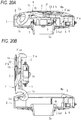
- the cap 1 is capable of opening and closing the fuel filler port Ta leading to the fuel tank of a vehicle by moving between the closed position where the fuel filler port Ta is closed (see Fig. 20A ) and the open position where the fuel filler port Ta is opened (see Fig. 20B ), and includes the upper cap portion 1a and the lower cap portion 1b.
- the cap 1 swings around the swing shaft La to move from the closed position to the open position, so that the fuel filler port Ta can be exposed to the outside.
- a curved arm portion 1c is formed in the upper cap portion 1a, and the swing shaft La around which the cap 1 swings between the closed position and the open position is formed at a predetermined position of the arm portion 1c. Further, the upper cap portion 1a holds the operation knob 2 (operation unit) at an upper portion thereof such that the operation knob 2 can be swung.
- the lower cap portion 1b is attached with a seal material S that seals the fuel filler port Ta when the cap 1 is in the closed position, and houses the engagement unit 3' with the engagement unit 3' being able to move between an engagement position and an allowable position as shown in Figs. 20A to 22B .
- Reference numeral 1d in Fig. 26 indicates a lid member that closes an upper portion of the lower cap portion 1b.
- the operation knob 2 (operation unit) has a swing shaft Lb formed integrally therewith as shown in Fig. 28 , has a protruding portion 2a formed at one end portion of the swing shaft Lb, and is attached to a recess formed on an upper surface of the cap 1 (upper cap portion 1a).
- the operation knob 2 can be operated to swing around the swing shaft Lb.
- the engagement unit 3' is movable in conjunction with the operation of the operation knob 2, and operates between the engagement position where a state in which the cap 1 closes the fuel filler port Ta is held (see Fig. 22A ), and the allowance position where the engagement is released and an opening operation of the cap 1 is allowed (see Fig. 22B ). More specifically, the engagement unit 3' according to the present embodiment is slidable in a substantially linear shape in a working space inside the lower cap portion 1b, and is configured such that when the engagement unit 3' is in the engagement position as shown in Fig.
- an engagement portion 3'aa at a tip end is engaged with the engaged portion Ha formed on the cover portion H to restrict the movement of the cap 1 from the closed position to the open position, and when operation knob 2 is operated and the engagement unit 3' is in the allowable position as shown in Fig. 22B , the engagement portion 3'aa is separated from the engaged portion Ha to be disengaged, and the movement of the cap 1 from the closed position to the open position is allowed.
- the engagement unit 3' is biased from the allowable position toward the engagement position by the biasing force of the coil spring 9 as shown in Figs. 22A and 22B , and has a tapered surface 3'ab formed on a back surface side of the engagement portion 3'aa as shown in Figs. 31 and 32 .
- the tapered surface 3'ab interferes with the engaged portion Ha of the cover portion H, and the engagement unit 3' slightly moves toward the allowable position against the biasing force of the coil spring 9.
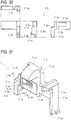
- the engagement unit 3' includes a first engagement unit 3'a having the engagement portion 3'aa that restricts the movement of the cap 1 from the closed position to the open position, and a second engagement unit 3'b receiving an operation force from the operation knob 2.
- the overload preventing unit 15 is interposed and attached between the first engagement unit 3'a and the second engagement unit 3'b.
- the first engagement unit 3'a includes the engagement portion 3'aa configured to engage with the engaged portion Ha formed on the cover portion H, the tapered surface 3'ab formed on the back surface side of the engagement portion 3'aa, an extended portion 3'ac extending in a sliding direction of the first engagement unit 3'a, an interfered portion 3'ad formed on a back surface side of the first engagement unit 3'a, a tapered surface 3'ae formed at a predetermined position of the interfered portion 3'ad, and a contact portion 3'af formed on a tip end portion of the first engagement unit 3'a.
- the first engagement unit 3'a has a fitting portion K into which the second engagement unit 3'b can be fitted, an insertion portion 3'ah is extended on one side portion of the fitting portion K, and a recess 3'ai into which a connecting member 15a described later can be fitted is formed at a predetermined position of the insertion portion 3'ah.
- the extended portion 3'ac is a part integrally extended from the first engagement unit 3'a, and one end of the coil spring 9 can be brought into contact with an end portion 3'ag of the first engagement unit 3'a as shown in Figs. 23 to 25 .
- the second engagement unit 3'b includes a stepped portion 3'ba to be brought into contact with the protruding portion 2a of the operation knob 2, an extended portion 3'bb extending in a sliding direction of the second engagement unit 3'b, a housing recess 3'bd in which the overload preventing unit 15 can be housed, and an insertion groove 3'be through which the insertion portion 3ah of the first engagement unit 3'a can be inserted.
- the extended portion 3'bb is a part integrally extended from the second engagement unit 3'b, and one end of the coil spring 9 can be brought into contact with an end portion 3'bc of the second engagement unit 3'b as shown in Figs. 23 to 25 .
- the second engagement unit 3'b While the insertion portion 3'ah of the first engagement unit 3'a is inserted through the insertion groove 3'be of the second engagement unit 3'b, the second engagement unit 3'b is fitted into the fitting portion K formed in the first engagement unit 3'a, and the overload preventing unit 15 is housed in the housing recess 3'bd of the second engagement unit 3'b, so that the first engagement unit 3'a and the second engagement unit 3'b are connected by the overload preventing unit 15 to obtain the integrated engagement unit 3' as shown in Figs. 31 to 33B .
- the overload preventing unit 15 includes the connecting member 15a and a biasing member 15b which are housed in the housing recess 3'bd of the second engagement unit 3'b.
- the overload preventing unit 15 is attached to one of the first engagement unit 3'a and the second engagement unit 3'b (the housing recess 3'bd of the second engagement unit 3'b in the present embodiment) and applies a biasing force by a biasing unit to the other (the recess 3'ai of the first engagement unit 3'a in the present embodiment), so that the first engagement unit and the second engagement unit can be connected.
- the biasing member 15b (biasing unit) according to the present embodiment is formed of a coil spring, and is capable of applying a biasing force to the connecting member 15a.
- the connecting member 15a is pressed by the biasing force of the biasing member 15b and fitted into the recess 3'ai of the first engagement unit 3'a.
- the first engagement unit 3'a and the second engagement unit 3'b are connected by the biasing force of the overload preventing unit 15 and can be slid together.
- the overload prevention unit 15 is designed to, when a load of a predetermined amount or more is generated during the swing operation of the operation knob 2, release the load and maintain an engaged state of the engagement unit 3' (the engaged state of the engagement portion 3'aa with respect to the engaged portion Ha).
- a connecting force between the first engagement unit 3'a and the second engagement unit 3'b is maintained by the biasing force of the biasing member 15b of the overload preventing unit 15, and when a load equal to or greater than the connecting force (the load of a predetermined amount or more) is generated during the swing operation of the operation unit, the connection between the first engagement unit 3'a and the second engagement unit 3'b is released, and the load is released by relative movement.
- the lock unit is provided to lock movement of the engagement unit 3' from the engagement position to the allowable position, or to release the lock to allow the movement of the engagement unit 3' from the engagement position to the allowable position.
- the lock unit according to the present embodiment is formed of the solenoid 5 with a plunger 5a whose position is changeable by energization, and the plunger 5a configures a lock member that is movable between an interference position where the plunger 5a interferes with the interfered portion 3'ad formed at a predetermined position of the engagement unit 3' (first engagement unit 3'a) and locks, and a non-interference position where the plunger 5a does not interfere with the interfered portion 3'ad and the lock is released when the engagement unit 3' moves from the engagement position to the allowable position by the swing operation of the operation knob 2.
- the position of the plunger 5a can be changed between a protruding state and a contracted state by energization, and is set to the interference position under the protruding state and to the non-interference position under the contracted state, and the plunger 5a is constantly biased in a direction from the contracted state (non-interference position) to the protruding state (interference position) by a spring (not shown) formed inside the solenoid 5.
- the plunger 5a when the plunger 5a is not energized, the plunger 5a is in the protruding state (interference position) due to the biasing force of the spring provided therein such that the engagement unit 3' is locked, and when the plunger 5a is energized, the plunger 5a is in the contracted state (non-interference position) against the biasing force of the spring therein such that the engagement unit 3' is unlocked.
- the interfered portion 3'ad is a portion integrally formed on the back surface side of the engagement unit 3' and protruding downward.
- the plunger 5a in the interference position interferes with a side surface of the interfered portion 3'ad to restrict the movement of the engagement unit 3' toward the allowable position and lock the engagement unit 3';
- the plunger 5a is moved from the interference position to the non-interference position by energizing the solenoid 5, the lock is released, so that the engagement unit 3' is allowed to move toward the allowable position, the lock is released, and the cap 1 can be swung to the open position.
- the tapered surface 3'ae is formed on a protruding end of the interfered portion 3'ad so as to come into contact with the plunger 5a (lock member) such that the plunger 5a is moved from the interference position to the non-interference position when the cap 1 moves from the open position to the closed position. That is, when trying to swing the cap 1 from the open position to the closed position, the tapered surface 3'ae of the interfered portion 3'ad of the engagement unit 3' is set to come into contact with the plunger 5a, and in a process of swinging the cap 1 to the closed position, the tapered surface 3'ae can press the plunger 5a to move it from the interference position to the non-interference position.
- the slider 6 interlocking with the engagement unit 3', and the detection switch 8 capable of detecting the movement of the slider 6 are provided, and the lock can be released by the solenoid 5 (lock unit) on condition that the detection switch 8 detects the movement of the slider 6.
- the slider 6 is biased to the left side in the figure by the coil spring 7, and is assembled with the protruding end of the protruding portion 6a being in contact with the contact portion 3'af of the engagement unit 3' (first engagement unit 3'a).
- the slider 6 has a pressing surface 6b capable of pressing an operation portion 8a of the detection switch 8 at a position different from the protruding portion 6a, and is configured such that the pressing surface 6b presses the operation portion 8a to electrically turn on the detection switch 8, or the pressing surface 6b is separated from the operation portion 8a to electrically turn off the detection switch 8, depending on the movement of the slider 6.
- the slider 6 When the engagement unit 3' is in the engagement position, the slider 6 is in a state in which the pressing surface 6b is separated from the operation portion 8a, and the detection switch 8 is in an electrically off state.
- the operation knob 2 When the operation knob 2 is started and the engagement unit 3' starts to move from the engagement position toward the allowable position, the slider 6 moves in the same direction following the engagement unit 3' by the biasing force of the coil spring 7, the pressing surface 6b presses the operation portion 8a, and the detection switch 8 is electrically turned on. In this way, when the detection switch 8 detects the movement of the slider 6 and is electrically turned on, the solenoid 5 is energized and the lock is released. Therefore, by continuously operating the operation knob 2, the engagement unit 3' is moved to the allowable position.
- a vehicle applied to the present embodiment has the transmission unit 11 that can be carried by a driver and is configured to transmit a vehicle-specific ID code by radio waves, the receiving unit 12 that is arranged on a vehicle side and capable of receiving the ID code from the transmission unit 11, and the determination unit 13 that determines whether the ID code received by the receiving unit 12 is authorized for the vehicle (see Fig. 18 ); and transmits a control signal to the ECU 14 to permit engine start on condition that the determination unit 13 determines that the received ID code is authorized.
- the determination unit 13 is electrically connected to the detection switch 8, and on condition that the determination unit 13 determines that a received ID code is authorized and the movement of the engagement unit 3' is detected by the detection switch 8, the plunger 5a of the solenoid 5 is set in the contracted state to the non-interference position, so that the lock is released.
- the plunger 5a of the solenoid 5 is moved from the protruding state (interference position) to the contracted state (non-interference position) to release the lock of the lock unit, and the movement of the engagement unit 3' from the engagement position to the allowable position is allowed; while in a case where the determination unit 13 determines that a received ID code is not authorized, even if the start of movement of the engagement unit 3' is detected by the detection switch 8, the plunger 5a of the solenoid 5 is kept in the protruding state (interference position) so that the lock release operation is not performed by the lock unit.
- the lock unit (solenoid 5) includes the lock member (plunger 5a) that is movable between the interference position where the plunger 5a interferes with the interfered portion 3'ad formed at the predetermined position of the engagement unit 3' and locks, and the non-interference position where the plunger 5a does not interfere with the interfered portion 3'ad and the lock is released when the engagement unit 3' moves from the engagement position to the allowable position by the swing operation of the operation knob 2. Therefore, when the cap 1 is in the open position, erroneous operation of the lock unit can be prevented, and when swinging the cap 1 to the closed position, the lock can be reliably performed by the lock unit.
- the engagement unit 3' is directly locked or unlocked as compared with one in related art that locks or unlocks a slider interlocking with the engagement unit 3', so that erroneous operation of the lock unit can be prevented when the cap 1 is in the open position. Further, there is no fitting recess for fitting in the engagement unit 3 as in related art, so that there is no problem like foreign matter being clogged in the fitting recess, and a problem generated when the cap 1 swings to the closed position can be avoided.
- the lock member (plunger 5a) according to the present embodiment is pressed by the interfered portion 3'ad and moved from the interference position to the non-interference position, so that the cap 1 can swing to the closed position without being interfered by the lock member, and the engagement unit 3' in the engagement position can be reliably locked by the lock unit.
- the interfered portion 3'ad according to the present embodiment is formed with the taper surface 3'ae that comes into contact with the lock member (plunger 5a) such that the plunger 5a is moved from the interference position to the non-interference position when the cap 1 moves from the open position to the closed position, so that the lock member can be smoothly moved from the interference position to the non-interference position.
- the lock unit according to the present embodiment is formed of the solenoid 5 with the plunger 5a whose position is changeable by energization, and the lock member is formed of the plunger 5a, so that the responsiveness is high and the engagement unit 3' can be locked or unlocked reliably.
- the slider 6 interlocking with the engagement unit 3', and the detection switch 8 capable of detecting the movement of the slider 6 are provided, and the lock can be released by the lock unit on condition that the detection switch 8 detects the movement of the slider 6, so that the movement of the engagement unit 3' can be detected by the detection switch 8 via the slider 6. Therefore, the arrangement position and the arrangement direction (the direction in which the operation portion 8a is pressed) of the detection switch 8 can be optionally set, and the degree of freedom of layout can be improved.
- the transmission unit 11 that can be carried by a driver and is configured to transmit a vehicle-specific ID code
- the receiving unit 12 that is arranged on a vehicle side and capable of receiving the ID code from the transmission unit
- the determination unit 13 that determines whether the ID code received by the receiving unit 12 is authorized for the vehicle are provided, and the lock can be released by the locking unit only when the determination unit 13 determines that a received ID code is authorized. Therefore, it is possible to prevent a third party from illegally unlocking by the lock unit, so as to improve the prevention of crime.
- the lock is released by the lock unit on condition that the determination unit 13 determines that a received ID code is authorized and the movement of the engagement unit 3' is detected, so that the lock can be released in the process of operating the operation knob 2, and the operability can be improved as compared with, for example, a case where the lock is released by a separate operation unit (access switch or the like) attached to the vehicle side.
- the overload preventing unit 15 is provided to, when a load of a predetermined amount or more is generated during the swing operation of the operation knob 2, release the load and maintain the engaged state of the engagement unit 3', so that it is possible to prevent damage or deformation of the operation knob 2 or the engagement unit 3' due to overload during operation of the operation knob 2, and to prevent a third party from illegally releasing, by operating the operation knob 2 with an excessive force, the engagement of the engagement unit 3' locked by the lock unit, thereby improving the prevention of crime.
- the overload preventing unit 15 is interposed and attached between the first engagement unit 3'a and the second engagement unit 3'b, and is configured such that in the swing process of the operation knob 2, the first engagement unit 3'a and the second engagement unit 3'b are integrally moved when a load of a predetermined amount or more does not occur, and an operation force received by the second engagement unit 3'b is not transmitted to the first engagement unit 3'a when a load of a predetermined amount or more occurs, so that the overload generated during the swing operation of the operation knob 2 can be released reliably and smoothly.
- the overload preventing unit 15 connects the first engagement unit 3'a and the second engagement unit 3'b by being attached to one of the first engagement unit 3'a and the second engagement unit 3'b and applying a biasing force by the biasing member 15b (biasing unit) to the other, so that by adjusting the biasing force of the biasing member 15b, the connecting force between the first engagement unit 3'a and the second engagement unit 3'b can be adjusted, and the load of a predetermined amount or more can be optionally adjusted.
- biasing member 15b biasing unit
- the lock unit is not limited to the solenoid 5, and may be another actuator or the like as long as the lock unit includes a lock member that is movable between the interference position where the lock member interferes with the interfered portion (3d, 3'ad) formed at a predetermined position of the engagement unit (3, 3') and locks, and a non-interference position where the lock member does not interfere with the interfered portion (3d, 3'ad) and the lock is released when the engagement unit 3 moves from the engagement position to the allowable position by the swing operation of the operation knob 2 (operation unit).
- the solenoid 5 as the lock unit, the slider 6, and the detection switch 8 are integrated in the unit 4, but the components may be separately arranged without the unit 4. Further, in the first and second embodiments, the movement of the engagement unit 3 is detected by the detection switch 8 via the slider 6, but the movement of the engagement unit 3 may be directly detected by the detection switch 8.
- the overload preventing unit 15 connects the first engagement unit 3'a and the second engagement unit 3'b by being attached to the second engagement unit 3'b and applying a biasing force by the biasing member 15b (biasing unit) to the first engagement unit 3'a, but the overload preventing unit 15 may also connect the first engagement unit 3'a and the second engagement unit 3'b by being attached to the first engagement unit 3'a and applying a biasing force by the biasing member 15b (biasing unit) to the second engagement unit 3'b.
- the overload preventing unit 15 has a structure in which the connecting member 15a is biased by the biasing member 15b, but the overload preventing unit 15 may have another structure (for example, the biasing member 15b is another biasing unit or the connecting force between the first engagement unit 3'a and the second engagement unit 3'b is maintained solely by frictional force).
- An applied vehicle may be a buggy, a snow vehicle or the like in addition to an automobile or a motorcycle.
- the fuel tank cap locking device is one in which the lock unit includes a lock member that is movable between an interference position where the lock member interferes with an interfered portion formed at a predetermined position of the engagement unit and locks, and a non-interference position where the lock member does not interfere with the interfered portion and the lock is released when the engagement unit moves from the engagement position to the allowable position by the swing operation of the operation unit, and can be applied to a device having a different external shape or a device having other functions.
- a fuel tank cap locking device comprising: a cap that is configured to open and close a fuel filler port leading to a fuel tank of a vehicle by moving between a closed position where the fuel filler port is closed, and an open position where the fuel filler port is opened; an operation unit that is configured to be allowed to perform a swing operation around a swing shaft by an operator; an engagement unit that is movable in conjunction with the swing operation of the operation unit, and that is configured to operate between an engagement position where a state in which the cap closes the fuel filler port is held, and an allowable position where engagement is released and an opening operation of the cap is allowed; and a lock unit that is configured to lock movement of the engagement unit from the engagement position to the allowable position, or release lock to allow the movement of the engagement unit from the engagement position to the allowable position, wherein the lock unit includes a lock member that is movable between an interference position where the lock member interferes with an interfered portion formed at a predetermined position of the engagement unit and locks
- the lock unit includes the lock member that is movable between the interference position where the lock member interferes with the interfered portion formed at the predetermined position of the engagement unit and locks, and the non-interference position where the lock member does not interfere with the interfered portion and the lock is released when the engagement unit moves from the engagement position to the allowable position by the swing operation of the operation unit. Therefore, when the cap is in the open position, erroneous operation of the lock unit can be prevented, and when swinging the cap to the closed position, the lock can be reliably performed by the lock unit.
- the lock member may be pressed by the interfered portion and moved from the interference position to the non-interference position when the cap moves from the open position to the closed position.
- the lock member when the cap moves from the open position to the closed position, the lock member is pressed by the interfered portion and moved from the interference position to the non-interference position, so that the cap can swing to the closed position without being interfered by the lock member, and the engagement unit in the engagement position can be reliably locked by the lock unit.
- the interfered portion may be formed with a tapered surface that comes into contact with the lock member such that the lock member is moved from the interference position to the non-interference position when the cap moves from the open position to the closed position.
- the interfered portion is formed with the taper surface that comes into contact with the lock member such that the lock member is moved from the interference position to the non-interference position when the cap moves from the open position to the closed position, so that the lock member can be smoothly moved from the interference position to the non-interference position.
- the lock unit may include a solenoid with a plunger whose position is changeable by energization, and the lock member may include the plunger.
- the lock unit includes the solenoid with the plunger whose position is changeable by energization, and the lock member includes the plunger, so that the responsiveness is high and the engagement unit can be locked or unlocked reliably.
- the fuel tank cap locking device may further comprise: a slider that is configured to interlock with the engagement unit; and a detection switch that is configured to detect movement of the slider. Lock may be released by the lock unit on condition that the detection switch detects the movement of the slider.
- the slider interlocking with the engagement unit, and the detection switch capable of detecting the movement of the slider are provided, and the lock can be released by the lock unit on condition that the detection switch detects the movement of the slider, so that the movement of the engagement unit can be detected by the detection switch via the slider. Therefore, the arrangement position and the arrangement direction of the detection switch can be optionally set, and the degree of freedom of layout can be improved.
- the fuel tank cap locking device may further comprise: a transmission unit that is carried by a driver, and that is configured to transmit a vehicle-specific ID code; a receiving unit that is arranged on a vehicle side, and that is capable of receiving the ID code from the transmission unit; and a determination unit that is configured to determine whether the ID code received by the receiving unit is authorized for the vehicle.
- the lock may be released by the lock unit only in a case where the determination unit determines that the received ID code is authorized.
- the transmission unit that can be carried by a driver and is configured to transmit a vehicle-specific ID code
- the receiving unit that is arranged on a vehicle side and capable of receiving the ID code from the transmission unit
- the determination unit that determines whether the ID code received by the receiving unit is authorized for the vehicle are provided, and the lock can be released by the locking unit only when the determination unit determines that a received ID code is authorized. Therefore, it is possible to prevent a third party from illegally unlocking by the lock unit, so as to improve the prevention of crime.
- the lock may be released by the lock unit on condition that the determination unit determines that the received ID code is authorized, and movement of the engagement unit is detected.
- the lock is released by the lock unit on condition that the determination unit determines that a received ID code is authorized and the movement of the engagement unit is detected, so that the lock can be released in the process of operating the operation unit, and the operability can be improved.
- the fuel tank cap locking device may further comprise: an overload preventing unit that is configured to, when a load of a predetermined amount or more is generated during the swing operation of the operation unit, release the load and maintain an engaged state of the engagement unit.
- the overload preventing unit is provided to, when a load of a predetermined amount or more is generated during the swing operation of the operation unit, release the load and maintain the engaged state of the engagement unit, so that it is possible to prevent damage or deformation of the operation unit or the engagement unit due to overload during operation of the operation unit, and to prevent a third party from illegally releasing, by operating the operation unit with an excessive force, the engagement of the engagement unit locked by the lock unit, thereby improving the prevention of crime.
- the engagement unit may include: a first engagement unit that includes an engagement portion configured to restrict movement of the cap from the closed position to the open position; and a second engagement unit that is configured to receive an operation force from the operation unit.
- the overload preventing unit may be interposed and attached between the first engagement unit and the second engagement unit, and be configured such that during a swing process of the operation unit, the first engagement unit and the second engagement unit are integrally moved when the load of the predetermined amount or more does not occur, and the operation force received by the second engagement unit is not transmitted to the first engagement unit when the load of the predetermined amount or more occurs.
- the overload preventing unit is interposed and attached between the first engagement unit and the second engagement unit, and is configured such that in the swing process of the operation unit, the first engagement unit and the second engagement unit are integrally moved when a load of a predetermined amount or more does not occur, and an operation force received by the second engagement unit is not transmitted to the first engagement unit when a load of a predetermined amount or more occurs, so that the overload generated during the swing operation of the operation unit can be released reliably and smoothly.
- the overload preventing unit may be configured to connect the first engagement unit and the second engagement unit by being attached to one of the first engagement unit and the second engagement unit and applying a biasing force by a biasing unit to the other.
- the overload preventing unit connects the first engagement unit and the second engagement unit by being attached to one of the first engagement unit and the second engagement unit and applying a biasing force by the biasing unit to the other, so that by adjusting the biasing force of the biasing unit, the connecting force between the first engagement unit and the second engagement unit can be adjusted, and the load of a predetermined amount or more can be optionally adjusted.
Landscapes
- Engineering & Computer Science (AREA)
- Mechanical Engineering (AREA)
- Life Sciences & Earth Sciences (AREA)
- Sustainable Development (AREA)
- Sustainable Energy (AREA)
- Chemical & Material Sciences (AREA)
- Combustion & Propulsion (AREA)
- Transportation (AREA)
- Physics & Mathematics (AREA)
- Electromagnetism (AREA)
- Cooling, Air Intake And Gas Exhaust, And Fuel Tank Arrangements In Propulsion Units (AREA)
- Lock And Its Accessories (AREA)
Abstract
Description
- The present invention relates to a fuel tank cap locking device for locking or unlocking the opening and closing of a cap for closing a fuel filler port leading to a fuel tank.
- Normally, a fuel filler port is provided at the top of a fuel tank of in a large motorcycle, and there is proposed a fuel tank cap locking device including a cap that can open and close the fuel filler port by moving between a closed position where the fuel filler port is closed and an open position where the fuel filler port is opened, and a lock unit that locks or unlocks the opening and closing of the cap. For example, as a fuel tank cap locking device of related art,
Patent Literature 1 discloses a device including an operation knob that is allowed to perform a swing operation around a swing shaft by an operator, an engagement unit that is movable in conjunction with a swing operation of the operation knob, and operates between an engagement position where a state in which a cap closes a fuel filler port is held, and an allowance position where the engagement is released and an opening operation of the cap is allowed, and a lock unit that locks movement of the engagement unit from the engagement position to the allowable position, or releases the lock to allow the movement of the engagement unit from the engagement position to the allowable position. - Patent Literature 1: Italian Patent No.
1393382 - However, in the related art described above, the lock unit has a slider that fits with the cap in the closed position and interlocks with the engagement unit, and a solenoid that restricts movement of the slider or releases the restriction, so that the slider is visible from the outside when the cap is in the open position. As a result, there is a possibility of an erroneous operation in which the slider is accidentally slid and locked by the solenoid when the cap is in the open position.
- Further, in the related art described above, the slider is provided with a fitting recess for fitting and connecting with the engagement unit when the cap is in the closed position, and therefore, when the cap is in the open position, the fitting recess faces upward, and the fitting recess may be clogged with foreign matter. In this case, even if the cap is swung to the closed position, the engagement unit cannot be fitted in the fitting recess, and the lock by the lock unit may not be normally performed.
- The present invention is made in view of the above circumstances, and an object thereof is to provide a fuel tank cap locking device in which an erroneous operation of a lock unit can be prevented when a cap is in an open position, and lock can be reliably performed by the lock unit when swinging the cap to a closed position.
- According to an aspect of the invention, there is provided a fuel tank cap locking device comprising: a cap that is configured to open and close a fuel filler port leading to a fuel tank of a vehicle by moving between a closed position where the fuel filler port is closed, and an open position where the fuel filler port is opened; an operation unit that is configured to be allowed to perform a swing operation around a swing shaft by an operator; an engagement unit that is movable in conjunction with the swing operation of the operation unit, and that is configured to operate between an engagement position where a state in which the cap closes the fuel filler port is held, and an allowable position where engagement is released and an opening operation of the cap is allowed; and a lock unit that is configured to lock movement of the engagement unit from the engagement position to the allowable position, or release lock to allow the movement of the engagement unit from the engagement position to the allowable position, wherein the lock unit includes a lock member that is movable between an interference position where the lock member interferes with an interfered portion formed at a predetermined position of the engagement unit and locks, and a non-interference position where the lock member does not interfere with the interfered portion and the lock is released when the engagement unit moves from the engagement position to the allowable position by the swing operation of the operation unit.
-
-
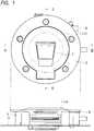
Fig. 1 is a plan view and a side view showing a fuel tank cap locking device according to a first embodiment of the present invention. -
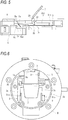
Figs. 2A and 2B are sectional views taken along line II-II inFig. 1 , in whichFig. 2A is a schematic view showing a state in which a cap is in a closed position, andFig. 2B is a schematic view showing a state in which the cap is in an open position. -
Fig. 3 is a sectional view taken along line III-III inFig. 1 . -
Fig. 4 is a schematic view showing a state before operating an operation unit in the fuel tank cap locking device (a state in which the engagement unit is in an engagement position). -
Fig. 5 is a schematic view showing a state after operating the operation unit in the fuel tank cap locking device (a state in which the engagement unit is in an allowable position). -
Fig. 6 is a plan view showing a state in which the cap is removed from the fuel tank cap locking device as viewed from above. -
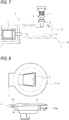
Fig. 7 is a schematic view showing a positional relationship between a solenoid and a slider with respect to the engagement unit in the fuel tank cap locking device. -
Fig. 8 is a plan view and a side view showing the cap of the fuel tank cap locking device. -
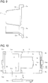
Fig. 9 is a plan view and a side view showing the operation unit of the fuel tank cap locking device. -
Fig. 10 is a four-side view showing the engagement unit of the fuel tank cap locking device. -
Fig. 11 is a perspective view showing the engagement unit of the fuel tank cap locking device. -
Fig. 12 is a back view showing the engagement unit. -
Fig. 13 is a perspective view showing a unit having the solenoid and the slider in the fuel tank cap locking device. -
Fig. 14 is a plan view and a side view showing the unit. -
Fig. 15 is a sectional view taken along line XV-XV inFig. 14 . -
Fig. 16 is a schematic view showing a positional relationship between the slider and a detection switch (off state) in the fuel tank cap locking device. -
Fig. 17 is a schematic view showing a positional relationship between the slider and the detection switch (on state) in the fuel tank cap locking device. -
Fig. 18 is a block diagram showing an overall configuration of the fuel tank cap locking device. -
Fig. 19 is a plan view and a side view showing a fuel tank cap locking device according to a second embodiment of the present invention. -
Figs. 20A and 20B are sectional views taken along line XX-XX inFig. 19 , in whichFig. 20A is a schematic view showing a state in which a cap is in a closed position, andFig. 20B is a schematic view showing a state in which a cap is in an open position. -
Fig. 21 is a sectional view taken along line XXI-XXI inFig. 19 . -
Figs. 22A and 22B are schematic views showing operation states of an operation unit of the fuel tank cap locking device, in whichFig. 22A is a schematic view showing a state before operating the operation unit (a state in which the engagement unit is in an engagement position), andFig. 22B is a schematic view showing a state after operating the operation unit (a state in which the engagement unit is in an allowable position). -
Fig. 23 is a perspective view showing a state in which the operation unit and the engagement unit are assembled in the fuel tank cap locking device. -
Fig. 24 is a perspective view showing the state in which the operation unit and the engagement unit are assembled in the fuel tank cap locking device. -
Fig. 25 is a perspective view showing an overload preventing unit connected with a first engagement unit and a second engagement unit in the fuel tank cap locking device. -
Fig. 26 is a perspective view showing a state in which a lock unit locks the engagement unit in the fuel tank cap locking device. -
Fig. 27 is a plan view and a side view showing the cap of the fuel tank cap locking device. -
Fig. 28 is a plan view and a side view showing the operation unit of the fuel tank cap locking device. -
Fig. 29 is a four-side view showing the first engagement unit of the fuel tank cap locking device. -
Fig. 30 is a four-side view showing the second engagement unit of the fuel tank cap locking device. -
Fig. 31 is a perspective view showing a state in which the first engagement unit and the second engagement unit are connected by the overload preventing unit in the fuel tank cap locking device. -
Fig. 32 is a perspective view showing the state in which the first engagement unit and the second engagement unit are connected with the overload preventing unit in the fuel tank cap locking device. -
Figs. 33A and 33B are back views showing the state in which the first engagement unit and the second engagement unit are connected with the overload preventing unit in the fuel tank cap locking device, in whichFig. 33A is a schematic view showing a state in which the first engagement unit and the second engagement unit are integrated, andFig. 33B is a schematic view showing a state in which the first engagement unit and the second engagement unit are relatively moved. -
Fig. 34 is a schematic view showing a positional relationship between a slider and a detection switch in the fuel tank cap locking device. - Hereinafter, embodiments of the present invention will be described in detail with reference to the drawings.
- A fuel tank cap locking device according to a first embodiment is a device for locking or unlocking the opening and closing of a cap for closing a fuel filler port leading to a fuel tank in a large motorcycle. As shown in
Figs. 1 to 3 , the fuel tank cap locking device includes acap 1, an operation knob 2 (operation unit), anengagement unit 3, asolenoid 5 as a lock unit, aslider 6, and adetection switch 8. The above components are housed in a main body R fixed to a fuel tank T having a fuel filler port Ta. As shown inFigs. 1 to 3 , an annular cover portion H is fixed to an upper portion of the main body R by a plurality of bolts. - The
cap 1 is capable of opening and closing the fuel filler port Ta leading to the fuel tank of a vehicle by moving between a closed position where the fuel filler port Ta is closed (seeFig. 2A ) and an open position where the fuel filler port Ta is opened (seeFig. 2B ), and includes anupper cap portion 1a and alower cap portion 1b. In the present embodiment, when an operator such as a driver picks up theoperation knob 2 by hand and pulls it up, thecap 1 swings around a swing shaft La to move from the closed position to the open position, so that the fuel filler port Ta can be exposed to the outside. - As shown in
Fig. 8 , the swing shaft La around which thecap 1 swings between the closed position and the open position is formed at a predetermined position of theupper cap portion 1a. Further, theupper cap portion 1a holds the operation knob 2 (operation unit) at an upper portion thereof such that theoperation knob 2 can be swung. Thelower cap portion 1b is attached with a seal material S that seals the fuel filler port Ta when thecap 1 is in the closed position, and houses theengagement unit 3 with theengagement unit 3 being able to move between an engagement position and an allowable position as shown inFigs. 4 to 6 . - The operation knob 2 (operation unit) has a swing shaft Lb formed integrally therewith as shown in
Fig. 9 , has protrudingportions 2a formed at both end portions of the swing shaft Lb respectively, and is attached to a recess formed on an upper surface of the cap 1 (upper cap portion 1a). When the operator pulls up theoperation knob 2 to operate it, theoperation knob 2 can be operated to swing around the swing shaft Lb. - The
engagement unit 3 is movable in conjunction with the operation of theoperation knob 2, and operates between the engagement position where a state in which thecap 1 closes the fuel filler port Ta is held (seeFig. 4 ), and the allowable position where the engagement is released and an opening operation of thecap 1 is allowed (seeFig. 5 ). More specifically, theengagement unit 3 according to the present embodiment is slidable in a substantially linear shape in a working space (seeFig. 6 ) inside thelower cap portion 1b, and is configured such that when theengagement unit 3 is in the engagement position as shown inFig. 4 , anengagement portion 3a at a tip end is engaged with an engaged portion Ha formed on the cover portion H to restrict movement of thecap 1 from the closed position to the open position, and whenoperation knob 2 is operated and theengagement unit 3 is in the allowable position as shown inFig. 5 , theengagement portion 3a is separated from the engaged portion Ha to be disengaged, and the movement of thecap 1 from the closed position to the open position is allowed. - Further, the
engagement unit 3 is biased from the allowable position toward the engagement position by a biasing force of acoil spring 9 as shown inFigs. 4 and5 , and has a tapered surface 3aa formed on a back surface side of theengagement portion 3a as shown inFig. 10 . When thecap 1 is swung from the open position to the closed position, the tapered surface 3aa interferes with the engaged portion Ha of the cover portion H, and theengagement unit 3 slightly moves toward the allowable position against the biasing force of thecoil spring 9. In this way, when theengagement unit 3 moves to reach a position where the tapered surface 3aa does not interfere with the engaged portion Ha, thecap 1 swings to the closed position and theengagement unit 3 moves to the engagement position by the biasing force of thecoil spring 9, so that theengagement portion 3a engages with the engaged portion Ha. - Further, as shown in
Figs. 10 to 12 , theengagement unit 3 according to the present embodiment includes, in addition to theengagement portion 3a and the tapered surface 3aa, steppedportions 3b,extended portions 3c, an interferedportion 3d formed on a back surface side of theengagement unit 3, and acontact portion 3e formed at a tip end portion of theengagement unit 3. Theextended portions 3c are formed of a pair of left and right portions integrally extended from both end portions of theengagement portion 3a, and end portions 3ca can be brought into contact with one end of thecoil spring 9 described above. Further, the steppedportions 3b located between theengagement portion 3a and theextended portions 3c are brought into contact with the protrudingportions 2a of theoperation knob 2 as shown inFigs. 4 and5 , and when theoperation knob 2 swings around the swing shaft Lb, the steppedportions 3b are pressed by the protrudingportions 2a such that theengagement unit 3 is moved from the engagement position to the allowable position. - Further, in the present embodiment, the lock unit is provided to lock movement of the
engagement unit 3 from the engagement position to the allowable position, or to release the lock to allow the movement of theengagement unit 3 from the engagement position to the allowable position. Specifically, the lock unit according to the present embodiment is formed of thesolenoid 5 with aplunger 5a whose position is changeable by energization, and theplunger 5a configures a lock member that is movable between an interference position where theplunger 5a interferes with the interferedportion 3d formed at a predetermined position of theengagement unit 3 and locks, and a non-interference position where theplunger 5a does not interfere with the interferedportion 3d and the lock is released when theengagement unit 3 moves from the engagement position to the allowable position by the swing operation of theoperation knob 2. - The position of the
plunger 5a can be changed between a protruding state and a contracted state by energization, and is set to the interference position under the protruding state and to the non-interference position under the contracted state, and theplunger 5a is constantly biased in a direction from the contracted state (non-interference position) to the protruding state (interference position) by a spring (not shown) formed inside thesolenoid 5. That is, when theplunger 5a is not energized, theplunger 5a is in the protruding state (interference position) due to the biasing force of the spring provided therein such that theengagement unit 3 is locked, and when theplunger 5a is energized, theplunger 5a is in the contracted state (non-interference position) against the biasing force of the spring therein such that theengagement unit 3 is unlocked. - On the other hand, as shown in
Figs. 10 to 12 , the interferedportion 3d according to the present embodiment is a portion integrally formed on the back surface side of theengagement unit 3 and protruding downward. When there is an attempt to move theengagement unit 3 from the engagement position to the allowable position while thecap 1 is in the closed position, theplunger 5a in the interference position interferes with a side surface of the interferedportion 3d to restrict the movement of theengagement unit 3 toward the allowable position and lock theengagement unit 3; when theplunger 5a is moved from the interference position to the non-interference position by energizing thesolenoid 5, the lock is released, so that theengagement unit 3 is allowed to move toward the allowable position, the lock is released, and thecap 1 can be swung to the open position. - Further, a tapered surface 3da is formed on a protruding end of the interfered
portion 3d so as to come into contact with theplunger 5a (lock member) such that theplunger 5a is moved from the interference position to the non-interference position when thecap 1 moves from the open position to the closed position. That is, when trying to swing thecap 1 from the open position to the closed position, the tapered surface 3da of the interferedportion 3d of theengagement unit 3 is set to come into contact with theplunger 5a, and in a process of swinging thecap 1 to the closed position, the tapered surface 3da can press theplunger 5a to move it from the interference position to the non-interference position. - In this way, when the
plunger 5a moves to reach a position (non-interference position) where theplunger 5a does not interfere with the interferedportion 3d, thecap 1 can be swung to the closed position, and then theplunger 5a is returned to the interference position by the spring provided therein. Therefore, when thecap 1 is swung from the open position to the closed position, a swinging force can naturally move theplunger 5a from the interference position to the non-interference position, so that the operability can be improved. - As shown in
Figs. 13 to 17 , thesolenoid 5 according to the present embodiment is housed in theunit 4 fixed at a predetermined position in the main body R, and theplunger 5a is in a state of protruding to the outside of theunit 4. Theunit 4 includes anattachment case 10 to which theslider 6 and thedetection switch 8 are attached, and thesolenoid 5, theslider 6 and thedetection switch 8 are integrated parts. - Further, in the present embodiment, the
slider 6 interlocking with theengagement unit 3, and thedetection switch 8 capable of detecting the movement of theslider 6 are provided, and the lock can be released by the solenoid 5 (lock unit) on condition that thedetection switch 8 detects the movement of theslider 6. Specifically, as shown inFigs. 13 to 17 , theslider 6 and thedetection switch 8 are attached to theattachment case 10 that constitutes theunit 4, and a protrudingportion 6a of theslider 6 is in a state of protruding to the outside of theunit 4. Reference numeral f in the figure indicates a seal material for waterproofing. - The
slider 6 is biased to the right side inFigs. 16 and17 by thecoil spring 7 attached to theattachment case 10, and is assembled with a protruding end of the protrudingportion 6a being in contact with thecontact portion 3e of theengagement unit 3. Theslider 6 has apressing surface 6b capable of pressing anoperation portion 8a of thedetection switch 8 at a position different from the protrudingportion 6a, and is configured such that thepressing surface 6b presses theoperation portion 8a to electrically turn on the detection switch 8 (seeFig. 17 ), or thepressing surface 6b is separated from theoperation portion 8a to electrically turn off the detection switch 8 (seeFig. 16 ), depending on the movement of theslider 6. - When the
engagement unit 3 is in the engagement position, theslider 6 is in a state in which thepressing surface 6b is separated from theoperation portion 8a, and thedetection switch 8 is in an electrically off state as shown inFig. 16 . When theoperation knob 2 is started and theengagement unit 3 starts to move from the engagement position toward the allowable position, theslider 6 moves in the same direction following theengagement unit 3 by the biasing force of thecoil spring 7, thepressing surface 6b presses theoperation portion 8a, and thedetection switch 8 is electrically turned on. In this way, when thedetection switch 8 detects the movement of theslider 6 and is electrically turned on, thesolenoid 5 is energized and the lock is released. Therefore, by continuously operating theoperation knob 2, theengagement unit 3 is moved to the allowable position. - However, in the present embodiment, as shown in
Fig. 7 , in theunit 4, theplunger 5a of thesolenoid 5 and the protrudingportion 6a of theslider 6 protrude in respective predetermined directions, and are configured such that theplunger 5a interferes with the interferedportion 3d of theengagement unit 3, and the protrudingportion 6a is in contact with thecontact portion 3e. As a result, the relative positional relationship between the interference position of theplunger 5a and a contact position of theengagement unit 3 can be accurately maintained. - In addition, as shown in
Fig. 18 , a vehicle applied to the present embodiment has atransmission unit 11 that can be carried by a driver and is configured to transmit a vehicle-specific ID code by radio waves, a receivingunit 12 that is arranged on a vehicle side and capable of receiving the ID code from thetransmission unit 11, and adetermination unit 13 that determines whether the ID code received by the receivingunit 12 is authorized for the vehicle; and transmits a control signal to anECU 14 to permit engine start on condition that thedetermination unit 13 determines that the received ID code is authorized. - Further, the
determination unit 13 according to the present embodiment is electrically connected to thedetection switch 8, and on condition that thedetermination unit 13 determines that a received ID code is authorized and the movement of theengagement unit 3 is detected by thedetection switch 8, theplunger 5a of thesolenoid 5 is set in the contracted state to the non-interference position, so that the lock is released. That is, in a case where thedetermination unit 13 determines that a received ID code is authorized, and the start of movement of theengagement unit 3 is detected by thedetection switch 8, theplunger 5a of thesolenoid 5 is moved from the protruding state (interference position) to the contracted state (non-interference position) to release the lock of the lock unit, and the movement of theengagement unit 3 from the engagement position to the allowable position is allowed; while in a case where thedetermination unit 13 determines that a received ID code is not authorized, even if the start of movement of theengagement unit 3 is detected by thedetection switch 8, theplunger 5a of thesolenoid 5 is kept in the protruding state (interference position) so that the lock release operation is not performed by the lock unit. - According to the present embodiment, the lock unit (solenoid 5) includes the lock member (
plunger 5a) that is movable between the interference position where theplunger 5a interferes with the interferedportion 3d formed at the predetermined position of theengagement unit 3 and locks, and the non-interference position where theplunger 5a does not interfere with the interferedportion 3d and the lock is released when theengagement unit 3 moves from the engagement position to the allowable position by the swing operation of theoperation knob 2. Therefore, when thecap 1 is in the open position, erroneous operation of the lock unit can be prevented, and when swinging thecap 1 to the closed position, the lock can be reliably performed by the lock unit. - That is, according to the present embodiment, the
engagement unit 3 is directly locked or unlocked as compared with one in related art that locks or unlocks a slider interlocking with theengagement unit 3, so that erroneous operation of the lock unit can be prevented when thecap 1 is in the open position. Further, there is no fitting recess for fitting in theengagement unit 3 as in related art, so that there is no problem like foreign matter being clogged in the fitting recess, and a problem generated when thecap 1 swings to the closed position can be avoided. - When the
cap 1 moves from the open position to the closed position, the lock member (plunger 5a) according to the present embodiment is pressed by the interferedportion 3d and moved from the interference position to the non-interference position, so that thecap 1 can swing to the closed position without being interfered by the lock member, and theengagement unit 3 in the engagement position can be reliably locked by the lock unit. - Further, the interfered
portion 3d according to the present embodiment is formed with the taper surface 3da that comes into contact with the lock member (plunger 5a) such that theplunger 5a is moved from the interference position to the non-interference position when thecap 1 moves from the open position to the closed position, so that the lock member can be smoothly moved from the interference position to the non-interference position. In particular, the lock unit according to the present embodiment is formed of thesolenoid 5 with theplunger 5a whose position is changeable by energization, and the lock member is formed of theplunger 5a, so that the responsiveness is high and theengagement unit 3 can be locked or unlocked reliably. - Further, the
slider 6 interlocking with theengagement unit 3, and thedetection switch 8 capable of detecting the movement of theslider 6 are provided, and the lock can be released by the lock unit on condition that thedetection switch 8 detects the movement of theslider 6, so that the movement of theengagement unit 3 can be detected by thedetection switch 8 via theslider 6. Therefore, the arrangement position and the arrangement direction (the direction in which theoperation portion 8a is pressed) of thedetection switch 8 can be optionally set, and the degree of freedom of layout can be improved. - In addition, the
transmission unit 11 that can be carried by a driver and is configured to transmit a vehicle-specific ID code, the receivingunit 12 that is arranged on a vehicle side and capable of receiving the ID code from the transmission unit, and thedetermination unit 13 that determines whether the ID code received by the receivingunit 12 is authorized for the vehicle are provided, and the lock can be released by the locking unit only when thedetermination unit 13 determines that a received ID code is authorized. Therefore, it is possible to prevent a third party from illegally unlocking by the lock unit, so as to improve the prevention of crime. - In particular, the lock is released by the lock unit on condition that the
determination unit 13 determines that a received ID code is authorized and the movement of theengagement unit 3 is detected, so that the lock can be released in the process of operating theoperation knob 2, and the operability can be improved as compared with, for example, a case where the lock is released by a separate operation unit (access switch or the like) attached to the vehicle side. - Next, a fuel tank cap locking device according to a second embodiment of the present invention will be described.
- As in the first embodiment, the fuel tank cap locking device according to the second embodiment is a device for locking or unlocking the opening and closing of a cap for closing a fuel filler port leading to a fuel tank in a large motorcycle. As shown in
Figs. 19 to 22B , the fuel tank cap locking device includes thecap 1, the operation knob 2 (operation unit), an engagement unit 3', thesolenoid 5 as the lock unit, theslider 6, thedetection switch 8, and anoverload preventing unit 15. In the present embodiment, the above components are housed in a main body T having the fuel filler port Ta. As shown inFigs. 19 to 22B , the annular cover portion H is fixed to an upper portion of the main body T by a plurality of bolts. - The
cap 1 is capable of opening and closing the fuel filler port Ta leading to the fuel tank of a vehicle by moving between the closed position where the fuel filler port Ta is closed (seeFig. 20A ) and the open position where the fuel filler port Ta is opened (seeFig. 20B ), and includes theupper cap portion 1a and thelower cap portion 1b. In the present embodiment, when an operator such as a driver picks up theoperation knob 2 by hand and pulls it up, thecap 1 swings around the swing shaft La to move from the closed position to the open position, so that the fuel filler port Ta can be exposed to the outside. - As shown in
Fig. 27 , acurved arm portion 1c is formed in theupper cap portion 1a, and the swing shaft La around which thecap 1 swings between the closed position and the open position is formed at a predetermined position of thearm portion 1c. Further, theupper cap portion 1a holds the operation knob 2 (operation unit) at an upper portion thereof such that theoperation knob 2 can be swung. Thelower cap portion 1b is attached with a seal material S that seals the fuel filler port Ta when thecap 1 is in the closed position, and houses the engagement unit 3' with the engagement unit 3' being able to move between an engagement position and an allowable position as shown inFigs. 20A to 22B .Reference numeral 1d inFig. 26 indicates a lid member that closes an upper portion of thelower cap portion 1b. - The operation knob 2 (operation unit) has a swing shaft Lb formed integrally therewith as shown in
Fig. 28 , has a protrudingportion 2a formed at one end portion of the swing shaft Lb, and is attached to a recess formed on an upper surface of the cap 1 (upper cap portion 1a). When the operator pulls up theoperation knob 2 to operate it, theoperation knob 2 can be operated to swing around the swing shaft Lb. - The engagement unit 3' is movable in conjunction with the operation of the
operation knob 2, and operates between the engagement position where a state in which thecap 1 closes the fuel filler port Ta is held (seeFig. 22A ), and the allowance position where the engagement is released and an opening operation of thecap 1 is allowed (seeFig. 22B ). More specifically, the engagement unit 3' according to the present embodiment is slidable in a substantially linear shape in a working space inside thelower cap portion 1b, and is configured such that when the engagement unit 3' is in the engagement position as shown inFig. 22A , an engagement portion 3'aa at a tip end is engaged with the engaged portion Ha formed on the cover portion H to restrict the movement of thecap 1 from the closed position to the open position, and whenoperation knob 2 is operated and the engagement unit 3' is in the allowable position as shown inFig. 22B , the engagement portion 3'aa is separated from the engaged portion Ha to be disengaged, and the movement of thecap 1 from the closed position to the open position is allowed. - Further, the engagement unit 3' is biased from the allowable position toward the engagement position by the biasing force of the
coil spring 9 as shown inFigs. 22A and 22B , and has a tapered surface 3'ab formed on a back surface side of the engagement portion 3'aa as shown inFigs. 31 and32 . When thecap 1 is swung from the open position to the closed position, the tapered surface 3'ab interferes with the engaged portion Ha of the cover portion H, and the engagement unit 3' slightly moves toward the allowable position against the biasing force of thecoil spring 9. In this way, when the engagement unit 3' moves to reach a position where the tapered surface 3'ab does not interfere with the engaged portion Ha, thecap 1 swings to the closed position and the engagement unit 3' moves to the engagement position by the biasing force of thecoil spring 9, so that the engagement portion 3'aa engages with the engaged portion Ha. - Here, as shown in
Figs. 23 to 25 andFigs. 31 to 33B , the engagement unit 3' according to the present embodiment includes a first engagement unit 3'a having the engagement portion 3'aa that restricts the movement of thecap 1 from the closed position to the open position, and a second engagement unit 3'b receiving an operation force from theoperation knob 2. Theoverload preventing unit 15 is interposed and attached between the first engagement unit 3'a and the second engagement unit 3'b. - More specifically, as shown in
Fig. 29 , the first engagement unit 3'a includes the engagement portion 3'aa configured to engage with the engaged portion Ha formed on the cover portion H, the tapered surface 3'ab formed on the back surface side of the engagement portion 3'aa, an extended portion 3'ac extending in a sliding direction of the first engagement unit 3'a, an interfered portion 3'ad formed on a back surface side of the first engagement unit 3'a, a tapered surface 3'ae formed at a predetermined position of the interfered portion 3'ad, and a contact portion 3'af formed on a tip end portion of the first engagement unit 3'a. - The first engagement unit 3'a has a fitting portion K into which the second engagement unit 3'b can be fitted, an insertion portion 3'ah is extended on one side portion of the fitting portion K, and a recess 3'ai into which a connecting
member 15a described later can be fitted is formed at a predetermined position of the insertion portion 3'ah. The extended portion 3'ac is a part integrally extended from the first engagement unit 3'a, and one end of thecoil spring 9 can be brought into contact with an end portion 3'ag of the first engagement unit 3'a as shown inFigs. 23 to 25 . - On the other hand, as shown in
Fig. 30 , the second engagement unit 3'b includes a stepped portion 3'ba to be brought into contact with the protrudingportion 2a of theoperation knob 2, an extended portion 3'bb extending in a sliding direction of the second engagement unit 3'b, a housing recess 3'bd in which theoverload preventing unit 15 can be housed, and an insertion groove 3'be through which the insertion portion 3ah of the first engagement unit 3'a can be inserted. The extended portion 3'bb is a part integrally extended from the second engagement unit 3'b, and one end of thecoil spring 9 can be brought into contact with an end portion 3'bc of the second engagement unit 3'b as shown inFigs. 23 to 25 . - While the insertion portion 3'ah of the first engagement unit 3'a is inserted through the insertion groove 3'be of the second engagement unit 3'b, the second engagement unit 3'b is fitted into the fitting portion K formed in the first engagement unit 3'a, and the
overload preventing unit 15 is housed in the housing recess 3'bd of the second engagement unit 3'b, so that the first engagement unit 3'a and the second engagement unit 3'b are connected by theoverload preventing unit 15 to obtain the integrated engagement unit 3' as shown inFigs. 31 to 33B . - The
overload preventing unit 15 according to the present embodiment includes the connectingmember 15a and a biasingmember 15b which are housed in the housing recess 3'bd of the second engagement unit 3'b. Theoverload preventing unit 15 is attached to one of the first engagement unit 3'a and the second engagement unit 3'b (the housing recess 3'bd of the second engagement unit 3'b in the present embodiment) and applies a biasing force by a biasing unit to the other (the recess 3'ai of the first engagement unit 3'a in the present embodiment), so that the first engagement unit and the second engagement unit can be connected. - The biasing
member 15b (biasing unit) according to the present embodiment is formed of a coil spring, and is capable of applying a biasing force to the connectingmember 15a. In a state where the first engagement unit 3'a and the second engagement unit 3'b are assembled, the connectingmember 15a is pressed by the biasing force of the biasingmember 15b and fitted into the recess 3'ai of the first engagement unit 3'a. As a result, the first engagement unit 3'a and the second engagement unit 3'b are connected by the biasing force of theoverload preventing unit 15 and can be slid together. - When the
operation knob 2 swings around the swing shaft Lb, the stepped portion 3'ba of the second engagement unit 3'b is pressed by the protrudingportion 2a, and the first engagement unit 3'a and the second engagement unit 3'b can be integrally moved from the engagement position to the allowable position. Here, theoverload prevention unit 15 according to the present embodiment is designed to, when a load of a predetermined amount or more is generated during the swing operation of theoperation knob 2, release the load and maintain an engaged state of the engagement unit 3' (the engaged state of the engagement portion 3'aa with respect to the engaged portion Ha). - That is, in a swing process of the
operation knob 2, when a load of a predetermined amount or more does not occur, as shown inFig. 33A , the first engagement unit and the second engagement unit are integrally moved to the allowable position, and the engagement of the engagement portion 3'aa with respect to the engaged portion Ha is released; when a load of a predetermined amount or more occurs, as shown inFig. 33B , the connectingmember 15a is detached from the recess 3'ai to release the fitting, and the second engagement unit 3'b moves relatively to the first engagement unit 3'a, so that the operation force received by the second engagement unit 3'b is not transmitted to the first engagement unit 3'a. - In the engagement unit 3' according to the present embodiment, a connecting force between the first engagement unit 3'a and the second engagement unit 3'b is maintained by the biasing force of the biasing
member 15b of theoverload preventing unit 15, and when a load equal to or greater than the connecting force (the load of a predetermined amount or more) is generated during the swing operation of the operation unit, the connection between the first engagement unit 3'a and the second engagement unit 3'b is released, and the load is released by relative movement. - Further, in the present embodiment, the lock unit is provided to lock movement of the engagement unit 3' from the engagement position to the allowable position, or to release the lock to allow the movement of the engagement unit 3' from the engagement position to the allowable position. Specifically, as in the first embodiment, the lock unit according to the present embodiment is formed of the
solenoid 5 with aplunger 5a whose position is changeable by energization, and theplunger 5a configures a lock member that is movable between an interference position where theplunger 5a interferes with the interfered portion 3'ad formed at a predetermined position of the engagement unit 3' (first engagement unit 3'a) and locks, and a non-interference position where theplunger 5a does not interfere with the interfered portion 3'ad and the lock is released when the engagement unit 3' moves from the engagement position to the allowable position by the swing operation of theoperation knob 2. - The position of the
plunger 5a can be changed between a protruding state and a contracted state by energization, and is set to the interference position under the protruding state and to the non-interference position under the contracted state, and theplunger 5a is constantly biased in a direction from the contracted state (non-interference position) to the protruding state (interference position) by a spring (not shown) formed inside thesolenoid 5. That is, when theplunger 5a is not energized, theplunger 5a is in the protruding state (interference position) due to the biasing force of the spring provided therein such that the engagement unit 3' is locked, and when theplunger 5a is energized, theplunger 5a is in the contracted state (non-interference position) against the biasing force of the spring therein such that the engagement unit 3' is unlocked. - On the other hand, as shown in
Fig. 26 , the interfered portion 3'ad according to the present embodiment is a portion integrally formed on the back surface side of the engagement unit 3' and protruding downward. When there is an attempt to move the engagement unit 3' from the engagement position to the allowable position while thecap 1 is in the closed position, theplunger 5a in the interference position interferes with a side surface of the interfered portion 3'ad to restrict the movement of the engagement unit 3' toward the allowable position and lock the engagement unit 3'; when theplunger 5a is moved from the interference position to the non-interference position by energizing thesolenoid 5, the lock is released, so that the engagement unit 3' is allowed to move toward the allowable position, the lock is released, and thecap 1 can be swung to the open position. - Further, the tapered surface 3'ae is formed on a protruding end of the interfered portion 3'ad so as to come into contact with the
plunger 5a (lock member) such that theplunger 5a is moved from the interference position to the non-interference position when thecap 1 moves from the open position to the closed position. That is, when trying to swing thecap 1 from the open position to the closed position, the tapered surface 3'ae of the interfered portion 3'ad of the engagement unit 3' is set to come into contact with theplunger 5a, and in a process of swinging thecap 1 to the closed position, the tapered surface 3'ae can press theplunger 5a to move it from the interference position to the non-interference position. - In this way, when the
plunger 5a moves to reach a position (non-interference position) where theplunger 5a does not interfere with the interfered portion 3'ad, thecap 1 can be swung to the closed position, and then theplunger 5a is returned to the interference position by the spring provided therein. Therefore, when thecap 1 is swung from the open position to the closed position, a swinging force can naturally move theplunger 5a from the interference position to the non-interference position, so that the operability can be improved. - Further, as in the first embodiment, in the present embodiment, the
slider 6 interlocking with the engagement unit 3', and thedetection switch 8 capable of detecting the movement of theslider 6 are provided, and the lock can be released by the solenoid 5 (lock unit) on condition that thedetection switch 8 detects the movement of theslider 6. Specifically, as shown inFig. 34 , theslider 6 is biased to the left side in the figure by thecoil spring 7, and is assembled with the protruding end of the protrudingportion 6a being in contact with the contact portion 3'af of the engagement unit 3' (first engagement unit 3'a). - The
slider 6 has apressing surface 6b capable of pressing anoperation portion 8a of thedetection switch 8 at a position different from the protrudingportion 6a, and is configured such that thepressing surface 6b presses theoperation portion 8a to electrically turn on thedetection switch 8, or thepressing surface 6b is separated from theoperation portion 8a to electrically turn off thedetection switch 8, depending on the movement of theslider 6. - When the engagement unit 3' is in the engagement position, the
slider 6 is in a state in which thepressing surface 6b is separated from theoperation portion 8a, and thedetection switch 8 is in an electrically off state. When theoperation knob 2 is started and the engagement unit 3' starts to move from the engagement position toward the allowable position, theslider 6 moves in the same direction following the engagement unit 3' by the biasing force of thecoil spring 7, thepressing surface 6b presses theoperation portion 8a, and thedetection switch 8 is electrically turned on. In this way, when thedetection switch 8 detects the movement of theslider 6 and is electrically turned on, thesolenoid 5 is energized and the lock is released. Therefore, by continuously operating theoperation knob 2, the engagement unit 3' is moved to the allowable position. - In addition, as in the first embodiment, a vehicle applied to the present embodiment has the
transmission unit 11 that can be carried by a driver and is configured to transmit a vehicle-specific ID code by radio waves, the receivingunit 12 that is arranged on a vehicle side and capable of receiving the ID code from thetransmission unit 11, and thedetermination unit 13 that determines whether the ID code received by the receivingunit 12 is authorized for the vehicle (seeFig. 18 ); and transmits a control signal to theECU 14 to permit engine start on condition that thedetermination unit 13 determines that the received ID code is authorized. - Further, the
determination unit 13 according to the present embodiment is electrically connected to thedetection switch 8, and on condition that thedetermination unit 13 determines that a received ID code is authorized and the movement of the engagement unit 3' is detected by thedetection switch 8, theplunger 5a of thesolenoid 5 is set in the contracted state to the non-interference position, so that the lock is released. That is, in a case where thedetermination unit 13 determines that a received ID code is authorized, and the start of movement of the engagement unit 3' is detected by thedetection switch 8, theplunger 5a of thesolenoid 5 is moved from the protruding state (interference position) to the contracted state (non-interference position) to release the lock of the lock unit, and the movement of the engagement unit 3' from the engagement position to the allowable position is allowed; while in a case where thedetermination unit 13 determines that a received ID code is not authorized, even if the start of movement of the engagement unit 3' is detected by thedetection switch 8, theplunger 5a of thesolenoid 5 is kept in the protruding state (interference position) so that the lock release operation is not performed by the lock unit. - According to the present embodiment, the lock unit (solenoid 5) includes the lock member (
plunger 5a) that is movable between the interference position where theplunger 5a interferes with the interfered portion 3'ad formed at the predetermined position of the engagement unit 3' and locks, and the non-interference position where theplunger 5a does not interfere with the interfered portion 3'ad and the lock is released when the engagement unit 3' moves from the engagement position to the allowable position by the swing operation of theoperation knob 2. Therefore, when thecap 1 is in the open position, erroneous operation of the lock unit can be prevented, and when swinging thecap 1 to the closed position, the lock can be reliably performed by the lock unit. - That is, according to the present embodiment, the engagement unit 3' is directly locked or unlocked as compared with one in related art that locks or unlocks a slider interlocking with the engagement unit 3', so that erroneous operation of the lock unit can be prevented when the
cap 1 is in the open position. Further, there is no fitting recess for fitting in theengagement unit 3 as in related art, so that there is no problem like foreign matter being clogged in the fitting recess, and a problem generated when thecap 1 swings to the closed position can be avoided. - When the
cap 1 moves from the open position to the closed position, the lock member (plunger 5a) according to the present embodiment is pressed by the interfered portion 3'ad and moved from the interference position to the non-interference position, so that thecap 1 can swing to the closed position without being interfered by the lock member, and the engagement unit 3' in the engagement position can be reliably locked by the lock unit. - Further, the interfered portion 3'ad according to the present embodiment is formed with the taper surface 3'ae that comes into contact with the lock member (
plunger 5a) such that theplunger 5a is moved from the interference position to the non-interference position when thecap 1 moves from the open position to the closed position, so that the lock member can be smoothly moved from the interference position to the non-interference position. In particular, the lock unit according to the present embodiment is formed of thesolenoid 5 with theplunger 5a whose position is changeable by energization, and the lock member is formed of theplunger 5a, so that the responsiveness is high and the engagement unit 3' can be locked or unlocked reliably. - Further, the
slider 6 interlocking with the engagement unit 3', and thedetection switch 8 capable of detecting the movement of theslider 6 are provided, and the lock can be released by the lock unit on condition that thedetection switch 8 detects the movement of theslider 6, so that the movement of the engagement unit 3' can be detected by thedetection switch 8 via theslider 6. Therefore, the arrangement position and the arrangement direction (the direction in which theoperation portion 8a is pressed) of thedetection switch 8 can be optionally set, and the degree of freedom of layout can be improved. - In addition, the
transmission unit 11 that can be carried by a driver and is configured to transmit a vehicle-specific ID code, the receivingunit 12 that is arranged on a vehicle side and capable of receiving the ID code from the transmission unit, and thedetermination unit 13 that determines whether the ID code received by the receivingunit 12 is authorized for the vehicle are provided, and the lock can be released by the locking unit only when thedetermination unit 13 determines that a received ID code is authorized. Therefore, it is possible to prevent a third party from illegally unlocking by the lock unit, so as to improve the prevention of crime. - In particular, the lock is released by the lock unit on condition that the
determination unit 13 determines that a received ID code is authorized and the movement of the engagement unit 3' is detected, so that the lock can be released in the process of operating theoperation knob 2, and the operability can be improved as compared with, for example, a case where the lock is released by a separate operation unit (access switch or the like) attached to the vehicle side. - In addition, according to the present embodiment, the
overload preventing unit 15 is provided to, when a load of a predetermined amount or more is generated during the swing operation of theoperation knob 2, release the load and maintain the engaged state of the engagement unit 3', so that it is possible to prevent damage or deformation of theoperation knob 2 or the engagement unit 3' due to overload during operation of theoperation knob 2, and to prevent a third party from illegally releasing, by operating theoperation knob 2 with an excessive force, the engagement of the engagement unit 3' locked by the lock unit, thereby improving the prevention of crime. - The
overload preventing unit 15 according to the present embodiment is interposed and attached between the first engagement unit 3'a and the second engagement unit 3'b, and is configured such that in the swing process of theoperation knob 2, the first engagement unit 3'a and the second engagement unit 3'b are integrally moved when a load of a predetermined amount or more does not occur, and an operation force received by the second engagement unit 3'b is not transmitted to the first engagement unit 3'a when a load of a predetermined amount or more occurs, so that the overload generated during the swing operation of theoperation knob 2 can be released reliably and smoothly. - Further, the
overload preventing unit 15 according to the present embodiment connects the first engagement unit 3'a and the second engagement unit 3'b by being attached to one of the first engagement unit 3'a and the second engagement unit 3'b and applying a biasing force by the biasingmember 15b (biasing unit) to the other, so that by adjusting the biasing force of the biasingmember 15b, the connecting force between the first engagement unit 3'a and the second engagement unit 3'b can be adjusted, and the load of a predetermined amount or more can be optionally adjusted. - The embodiments have been described above, but the present invention is not limited thereto. For example, the lock unit is not limited to the
solenoid 5, and may be another actuator or the like as long as the lock unit includes a lock member that is movable between the interference position where the lock member interferes with the interfered portion (3d, 3'ad) formed at a predetermined position of the engagement unit (3, 3') and locks, and a non-interference position where the lock member does not interfere with the interfered portion (3d, 3'ad) and the lock is released when theengagement unit 3 moves from the engagement position to the allowable position by the swing operation of the operation knob 2 (operation unit). - In the first embodiment, the
solenoid 5 as the lock unit, theslider 6, and thedetection switch 8 are integrated in theunit 4, but the components may be separately arranged without theunit 4. Further, in the first and second embodiments, the movement of theengagement unit 3 is detected by thedetection switch 8 via theslider 6, but the movement of theengagement unit 3 may be directly detected by thedetection switch 8. - In addition, the
overload preventing unit 15 according to the second embodiment connects the first engagement unit 3'a and the second engagement unit 3'b by being attached to the second engagement unit 3'b and applying a biasing force by the biasingmember 15b (biasing unit) to the first engagement unit 3'a, but theoverload preventing unit 15 may also connect the first engagement unit 3'a and the second engagement unit 3'b by being attached to the first engagement unit 3'a and applying a biasing force by the biasingmember 15b (biasing unit) to the second engagement unit 3'b. - Further, the
overload preventing unit 15 according to the second embodiment has a structure in which the connectingmember 15a is biased by the biasingmember 15b, but theoverload preventing unit 15 may have another structure (for example, the biasingmember 15b is another biasing unit or the connecting force between the first engagement unit 3'a and the second engagement unit 3'b is maintained solely by frictional force). An applied vehicle may be a buggy, a snow vehicle or the like in addition to an automobile or a motorcycle. - The fuel tank cap locking device is one in which the lock unit includes a lock member that is movable between an interference position where the lock member interferes with an interfered portion formed at a predetermined position of the engagement unit and locks, and a non-interference position where the lock member does not interfere with the interfered portion and the lock is released when the engagement unit moves from the engagement position to the allowable position by the swing operation of the operation unit, and can be applied to a device having a different external shape or a device having other functions.
- According to an aspect of the invention, there is provided a fuel tank cap locking device comprising: a cap that is configured to open and close a fuel filler port leading to a fuel tank of a vehicle by moving between a closed position where the fuel filler port is closed, and an open position where the fuel filler port is opened; an operation unit that is configured to be allowed to perform a swing operation around a swing shaft by an operator; an engagement unit that is movable in conjunction with the swing operation of the operation unit, and that is configured to operate between an engagement position where a state in which the cap closes the fuel filler port is held, and an allowable position where engagement is released and an opening operation of the cap is allowed; and a lock unit that is configured to lock movement of the engagement unit from the engagement position to the allowable position, or release lock to allow the movement of the engagement unit from the engagement position to the allowable position, wherein the lock unit includes a lock member that is movable between an interference position where the lock member interferes with an interfered portion formed at a predetermined position of the engagement unit and locks, and a non-interference position where the lock member does not interfere with the interfered portion and the lock is released when the engagement unit moves from the engagement position to the allowable position by the swing operation of the operation unit.
- According to the above aspect of the invention, the lock unit includes the lock member that is movable between the interference position where the lock member interferes with the interfered portion formed at the predetermined position of the engagement unit and locks, and the non-interference position where the lock member does not interfere with the interfered portion and the lock is released when the engagement unit moves from the engagement position to the allowable position by the swing operation of the operation unit. Therefore, when the cap is in the open position, erroneous operation of the lock unit can be prevented, and when swinging the cap to the closed position, the lock can be reliably performed by the lock unit.
- The lock member may be pressed by the interfered portion and moved from the interference position to the non-interference position when the cap moves from the open position to the closed position.
- In this case, when the cap moves from the open position to the closed position, the lock member is pressed by the interfered portion and moved from the interference position to the non-interference position, so that the cap can swing to the closed position without being interfered by the lock member, and the engagement unit in the engagement position can be reliably locked by the lock unit.
- The interfered portion may be formed with a tapered surface that comes into contact with the lock member such that the lock member is moved from the interference position to the non-interference position when the cap moves from the open position to the closed position.
- In this case, the interfered portion is formed with the taper surface that comes into contact with the lock member such that the lock member is moved from the interference position to the non-interference position when the cap moves from the open position to the closed position, so that the lock member can be smoothly moved from the interference position to the non-interference position.
- The lock unit may include a solenoid with a plunger whose position is changeable by energization, and the lock member may include the plunger.
- In this case, the lock unit includes the solenoid with the plunger whose position is changeable by energization, and the lock member includes the plunger, so that the responsiveness is high and the engagement unit can be locked or unlocked reliably.
- The fuel tank cap locking device may further comprise: a slider that is configured to interlock with the engagement unit; and a detection switch that is configured to detect movement of the slider. Lock may be released by the lock unit on condition that the detection switch detects the movement of the slider.
- In this case, the slider interlocking with the engagement unit, and the detection switch capable of detecting the movement of the slider are provided, and the lock can be released by the lock unit on condition that the detection switch detects the movement of the slider, so that the movement of the engagement unit can be detected by the detection switch via the slider. Therefore, the arrangement position and the arrangement direction of the detection switch can be optionally set, and the degree of freedom of layout can be improved.
- The fuel tank cap locking device may further comprise: a transmission unit that is carried by a driver, and that is configured to transmit a vehicle-specific ID code; a receiving unit that is arranged on a vehicle side, and that is capable of receiving the ID code from the transmission unit; and a determination unit that is configured to determine whether the ID code received by the receiving unit is authorized for the vehicle. The lock may be released by the lock unit only in a case where the determination unit determines that the received ID code is authorized.
- In this case, the transmission unit that can be carried by a driver and is configured to transmit a vehicle-specific ID code, the receiving unit that is arranged on a vehicle side and capable of receiving the ID code from the transmission unit, and the determination unit that determines whether the ID code received by the receiving unit is authorized for the vehicle are provided, and the lock can be released by the locking unit only when the determination unit determines that a received ID code is authorized. Therefore, it is possible to prevent a third party from illegally unlocking by the lock unit, so as to improve the prevention of crime.
- The lock may be released by the lock unit on condition that the determination unit determines that the received ID code is authorized, and movement of the engagement unit is detected.
- In this case, the lock is released by the lock unit on condition that the determination unit determines that a received ID code is authorized and the movement of the engagement unit is detected, so that the lock can be released in the process of operating the operation unit, and the operability can be improved.
- The fuel tank cap locking device may further comprise: an overload preventing unit that is configured to, when a load of a predetermined amount or more is generated during the swing operation of the operation unit, release the load and maintain an engaged state of the engagement unit.
- In this case, the overload preventing unit is provided to, when a load of a predetermined amount or more is generated during the swing operation of the operation unit, release the load and maintain the engaged state of the engagement unit, so that it is possible to prevent damage or deformation of the operation unit or the engagement unit due to overload during operation of the operation unit, and to prevent a third party from illegally releasing, by operating the operation unit with an excessive force, the engagement of the engagement unit locked by the lock unit, thereby improving the prevention of crime.
- The engagement unit may include: a first engagement unit that includes an engagement portion configured to restrict movement of the cap from the closed position to the open position; and a second engagement unit that is configured to receive an operation force from the operation unit. The overload preventing unit may be interposed and attached between the first engagement unit and the second engagement unit, and be configured such that during a swing process of the operation unit, the first engagement unit and the second engagement unit are integrally moved when the load of the predetermined amount or more does not occur, and the operation force received by the second engagement unit is not transmitted to the first engagement unit when the load of the predetermined amount or more occurs.
- In this case, the overload preventing unit is interposed and attached between the first engagement unit and the second engagement unit, and is configured such that in the swing process of the operation unit, the first engagement unit and the second engagement unit are integrally moved when a load of a predetermined amount or more does not occur, and an operation force received by the second engagement unit is not transmitted to the first engagement unit when a load of a predetermined amount or more occurs, so that the overload generated during the swing operation of the operation unit can be released reliably and smoothly.
- The overload preventing unit may be configured to connect the first engagement unit and the second engagement unit by being attached to one of the first engagement unit and the second engagement unit and applying a biasing force by a biasing unit to the other.
- In this case, the overload preventing unit connects the first engagement unit and the second engagement unit by being attached to one of the first engagement unit and the second engagement unit and applying a biasing force by the biasing unit to the other, so that by adjusting the biasing force of the biasing unit, the connecting force between the first engagement unit and the second engagement unit can be adjusted, and the load of a predetermined amount or more can be optionally adjusted.
Claims (10)
- A fuel tank cap locking device comprising:a cap that is configured to open and close a fuel filler port leading to a fuel tank of a vehicle by moving between a closed position where the fuel filler port is closed, and an open position where the fuel filler port is opened;an operation unit that is configured to be allowed to perform a swing operation around a swing shaft by an operator;an engagement unit that is movable in conjunction with the swing operation of the operation unit, and that is configured to operate between an engagement position where a state in which the cap closes the fuel filler port is held, and an allowable position where engagement is released and an opening operation of the cap is allowed; anda lock unit that is configured to lock movement of the engagement unit from the engagement position to the allowable position, or release lock to allow the movement of the engagement unit from the engagement position to the allowable position,wherein the lock unit includes a lock member that is movable between an interference position where the lock member interferes with an interfered portion formed at a predetermined position of the engagement unit and locks, and a non-interference position where the lock member does not interfere with the interfered portion and the lock is released when the engagement unit moves from the engagement position to the allowable position by the swing operation of the operation unit.
- The fuel tank cap locking device according to claim 1, wherein the lock member is pressed by the interfered portion and moved from the interference position to the non-interference position when the cap moves from the open position to the closed position.
- The fuel tank cap locking device according to claim 2, wherein the interfered portion is formed with a tapered surface that comes into contact with the lock member such that the lock member is moved from the interference position to the non-interference position when the cap moves from the open position to the closed position.
- The fuel tank cap locking device according to any one of claims 1 to 3, wherein the lock unit includes a solenoid with a plunger whose position is changeable by energization, and the lock member includes the plunger.
- The fuel tank cap locking device according to any one of claims 1 to 4, further comprising:a slider that is configured to interlock with the engagement unit; anda detection switch that is configured to detect movement of the slider,wherein lock is released by the lock unit on condition that the detection switch detects the movement of the slider.
- The fuel tank cap locking device according to any one of claims 1 to 5, further comprising:a transmission unit that is carried by a driver, and that is configured to transmit a vehicle-specific ID code;a receiving unit that is arranged on a vehicle side, and that is capable of receiving the ID code from the transmission unit; anda determination unit that is configured to determine whether the ID code received by the receiving unit is authorized for the vehicle,wherein the lock is released by the lock unit only in a case where the determination unit determines that the received ID code is authorized.
- The fuel tank cap locking device according to clam 6, wherein the lock is released by the lock unit on condition that the determination unit determines that the received ID code is authorized, and movement of the engagement unit is detected.
- The fuel tank cap locking device according to any one of claims 1 to 7, further comprising:
an overload preventing unit that is configured to, when a load of a predetermined amount or more is generated during the swing operation of the operation unit, release the load and maintain an engaged state of the engagement unit. - The fuel tank cap locking device according to claim 8,
wherein the engagement unit includes:a first engagement unit that includes an engagement portion configured to restrict movement of the cap from the closed position to the open position; anda second engagement unit that is configured to receive an operation force from the operation unit, andwherein the overload preventing unit is interposed and attached between the first engagement unit and the second engagement unit, and is configured such that during a swing process of the operation unit, the first engagement unit and the second engagement unit are integrally moved when the load of the predetermined amount or more does not occur, and the operation force received by the second engagement unit is not transmitted to the first engagement unit when the load of the predetermined amount or more occurs. - The fuel tank cap locking device according to claim 9, wherein the overload preventing unit is configured to connect the first engagement unit and the second engagement unit by being attached to one of the first engagement unit and the second engagement unit and applying a biasing force by a biasing unit to the other.
Applications Claiming Priority (2)
| Application Number | Priority Date | Filing Date | Title |
|---|---|---|---|
| JP2019107019 | 2019-06-07 | ||
| JP2019141010A JP7297248B2 (en) | 2019-06-07 | 2019-07-31 | Fuel tank cap locking device |
Publications (2)
| Publication Number | Publication Date |
|---|---|
| EP3760465A1 true EP3760465A1 (en) | 2021-01-06 |
| EP3760465B1 EP3760465B1 (en) | 2022-02-16 |
Family
ID=70977801
Family Applications (1)
| Application Number | Title | Priority Date | Filing Date |
|---|---|---|---|
| EP20178247.1A Active EP3760465B1 (en) | 2019-06-07 | 2020-06-04 | Fuel tank cap locking device |
Country Status (2)
| Country | Link |
|---|---|
| US (1) | US11685255B2 (en) |
| EP (1) | EP3760465B1 (en) |
Families Citing this family (4)
| Publication number | Priority date | Publication date | Assignee | Title |
|---|---|---|---|---|
| IT201800006901A1 (en) * | 2018-07-03 | 2020-01-03 | LOCK FOR VEHICLE DOOR WITH POSITION SENSOR. | |
| US11299038B2 (en) * | 2020-03-12 | 2022-04-12 | Nissan North America, Inc. | Fuel filler structure |
| JP7552363B2 (en) * | 2021-01-04 | 2024-09-18 | スズキ株式会社 | Fuel tank |
| JP7656483B2 (en) * | 2021-05-12 | 2025-04-03 | 本田技研工業株式会社 | Saddle-type vehicle |
Citations (4)
| Publication number | Priority date | Publication date | Assignee | Title |
|---|---|---|---|---|
| US20100156118A1 (en) * | 2008-12-18 | 2010-06-24 | Zadi S.P.A. | Cap for fuel tanks, in particular for motor cycles |
| US9579971B2 (en) * | 2013-08-08 | 2017-02-28 | Honda Motor Co., Ltd. | Fuel cap provided with breather mechanism |
| JP2017196951A (en) * | 2016-04-26 | 2017-11-02 | 朝日電装株式会社 | Fuel tank cap locking device |
| US9895998B2 (en) * | 2015-04-22 | 2018-02-20 | Toyota Jidosha Kabushiki Kaisha | Fuel cell-equipped vehicle and control method therefor |
Family Cites Families (3)
| Publication number | Priority date | Publication date | Assignee | Title |
|---|---|---|---|---|
| US4468058A (en) * | 1981-04-17 | 1984-08-28 | Kuhlman Corporation | Locking fuel cap |
| JP4346384B2 (en) | 2003-09-03 | 2009-10-21 | 朝日電装株式会社 | Fuel tank cap locking device |
| JP5864242B2 (en) | 2011-12-14 | 2016-02-17 | 株式会社東海理化電機製作所 | Lidlock control device |
-
2020
- 2020-06-04 EP EP20178247.1A patent/EP3760465B1/en active Active
- 2020-06-04 US US16/892,969 patent/US11685255B2/en active Active
Patent Citations (4)
| Publication number | Priority date | Publication date | Assignee | Title |
|---|---|---|---|---|
| US20100156118A1 (en) * | 2008-12-18 | 2010-06-24 | Zadi S.P.A. | Cap for fuel tanks, in particular for motor cycles |
| US9579971B2 (en) * | 2013-08-08 | 2017-02-28 | Honda Motor Co., Ltd. | Fuel cap provided with breather mechanism |
| US9895998B2 (en) * | 2015-04-22 | 2018-02-20 | Toyota Jidosha Kabushiki Kaisha | Fuel cell-equipped vehicle and control method therefor |
| JP2017196951A (en) * | 2016-04-26 | 2017-11-02 | 朝日電装株式会社 | Fuel tank cap locking device |
Also Published As
| Publication number | Publication date |
|---|---|
| US20200384853A1 (en) | 2020-12-10 |
| EP3760465B1 (en) | 2022-02-16 |
| US11685255B2 (en) | 2023-06-27 |
Similar Documents
| Publication | Publication Date | Title |
|---|---|---|
| EP3760465B1 (en) | Fuel tank cap locking device | |
| US8919828B2 (en) | Lock unit comprising two pawls and position detection means | |
| US11325463B2 (en) | Lock device of fuel tank cap | |
| JP2017196951A (en) | Fuel tank cap locking device | |
| US6428059B2 (en) | Latch detector for automotive door locks | |
| KR20020059402A (en) | Closing system, especially for motor vehicles | |
| EP1574385B1 (en) | Passive entry system | |
| EP2694336B1 (en) | Steering lock device | |
| JP4346384B2 (en) | Fuel tank cap locking device | |
| EP0634547A2 (en) | Door locking system for vehicles | |
| US20200122682A1 (en) | Locking device, in particular, for a motor vehicle | |
| US7985932B2 (en) | Door lock device with safety switch | |
| JP7297248B2 (en) | Fuel tank cap locking device | |
| JP5297771B2 (en) | Fuel tank cap locking device | |
| CN112313386A (en) | Unlocking device for unlocking a lock of a movable vehicle component and vehicle | |
| CN112292497A (en) | Locking system and method for operating a locking system | |
| JP2009262649A (en) | Lock device of fuel tank cap | |
| JP7309146B2 (en) | Fuel tank cap locking device | |
| JP4841228B2 (en) | Locking device | |
| JP2025171148A (en) | Vehicle locking device | |
| JPH09245584A (en) | Key switch | |
| JP2009051285A (en) | Fuel tank cap locking device | |
| JP4629498B2 (en) | Steering lock device | |
| US20040075542A1 (en) | Covering apparatus for remote transmitters | |
| JP2005314891A (en) | Locking device |
Legal Events
| Date | Code | Title | Description |
|---|---|---|---|
| PUAI | Public reference made under article 153(3) epc to a published international application that has entered the european phase |
Free format text: ORIGINAL CODE: 0009012 |
|
| STAA | Information on the status of an ep patent application or granted ep patent |
Free format text: STATUS: THE APPLICATION HAS BEEN PUBLISHED |
|
| AK | Designated contracting states |
Kind code of ref document: A1 Designated state(s): AL AT BE BG CH CY CZ DE DK EE ES FI FR GB GR HR HU IE IS IT LI LT LU LV MC MK MT NL NO PL PT RO RS SE SI SK SM TR |
|
| AX | Request for extension of the european patent |
Extension state: BA ME |
|
| STAA | Information on the status of an ep patent application or granted ep patent |
Free format text: STATUS: REQUEST FOR EXAMINATION WAS MADE |
|
| 17P | Request for examination filed |
Effective date: 20210705 |
|
| RBV | Designated contracting states (corrected) |
Designated state(s): AL AT BE BG CH CY CZ DE DK EE ES FI FR GB GR HR HU IE IS IT LI LT LU LV MC MK MT NL NO PL PT RO RS SE SI SK SM TR |
|
| GRAP | Despatch of communication of intention to grant a patent |
Free format text: ORIGINAL CODE: EPIDOSNIGR1 |
|
| STAA | Information on the status of an ep patent application or granted ep patent |
Free format text: STATUS: GRANT OF PATENT IS INTENDED |
|
| INTG | Intention to grant announced |
Effective date: 20210901 |
|
| GRAS | Grant fee paid |
Free format text: ORIGINAL CODE: EPIDOSNIGR3 |
|
| GRAA | (expected) grant |
Free format text: ORIGINAL CODE: 0009210 |
|
| STAA | Information on the status of an ep patent application or granted ep patent |
Free format text: STATUS: THE PATENT HAS BEEN GRANTED |
|
| AK | Designated contracting states |
Kind code of ref document: B1 Designated state(s): AL AT BE BG CH CY CZ DE DK EE ES FI FR GB GR HR HU IE IS IT LI LT LU LV MC MK MT NL NO PL PT RO RS SE SI SK SM TR |
|
| REG | Reference to a national code |
Ref country code: GB Ref legal event code: FG4D |
|
| REG | Reference to a national code |
Ref country code: CH Ref legal event code: EP |
|
| REG | Reference to a national code |
Ref country code: DE Ref legal event code: R096 Ref document number: 602020001866 Country of ref document: DE |
|
| REG | Reference to a national code |
Ref country code: AT Ref legal event code: REF Ref document number: 1468676 Country of ref document: AT Kind code of ref document: T Effective date: 20220315 |
|
| REG | Reference to a national code |
Ref country code: IE Ref legal event code: FG4D |
|
| REG | Reference to a national code |
Ref country code: LT Ref legal event code: MG9D |
|
| REG | Reference to a national code |
Ref country code: NL Ref legal event code: MP Effective date: 20220216 |
|
| PG25 | Lapsed in a contracting state [announced via postgrant information from national office to epo] |
Ref country code: SE Free format text: LAPSE BECAUSE OF FAILURE TO SUBMIT A TRANSLATION OF THE DESCRIPTION OR TO PAY THE FEE WITHIN THE PRESCRIBED TIME-LIMIT Effective date: 20220216 Ref country code: RS Free format text: LAPSE BECAUSE OF FAILURE TO SUBMIT A TRANSLATION OF THE DESCRIPTION OR TO PAY THE FEE WITHIN THE PRESCRIBED TIME-LIMIT Effective date: 20220216 Ref country code: PT Free format text: LAPSE BECAUSE OF FAILURE TO SUBMIT A TRANSLATION OF THE DESCRIPTION OR TO PAY THE FEE WITHIN THE PRESCRIBED TIME-LIMIT Effective date: 20220616 Ref country code: NO Free format text: LAPSE BECAUSE OF FAILURE TO SUBMIT A TRANSLATION OF THE DESCRIPTION OR TO PAY THE FEE WITHIN THE PRESCRIBED TIME-LIMIT Effective date: 20220516 Ref country code: NL Free format text: LAPSE BECAUSE OF FAILURE TO SUBMIT A TRANSLATION OF THE DESCRIPTION OR TO PAY THE FEE WITHIN THE PRESCRIBED TIME-LIMIT Effective date: 20220216 Ref country code: LT Free format text: LAPSE BECAUSE OF FAILURE TO SUBMIT A TRANSLATION OF THE DESCRIPTION OR TO PAY THE FEE WITHIN THE PRESCRIBED TIME-LIMIT Effective date: 20220216 Ref country code: HR Free format text: LAPSE BECAUSE OF FAILURE TO SUBMIT A TRANSLATION OF THE DESCRIPTION OR TO PAY THE FEE WITHIN THE PRESCRIBED TIME-LIMIT Effective date: 20220216 Ref country code: ES Free format text: LAPSE BECAUSE OF FAILURE TO SUBMIT A TRANSLATION OF THE DESCRIPTION OR TO PAY THE FEE WITHIN THE PRESCRIBED TIME-LIMIT Effective date: 20220216 Ref country code: BG Free format text: LAPSE BECAUSE OF FAILURE TO SUBMIT A TRANSLATION OF THE DESCRIPTION OR TO PAY THE FEE WITHIN THE PRESCRIBED TIME-LIMIT Effective date: 20220516 |
|
| PG25 | Lapsed in a contracting state [announced via postgrant information from national office to epo] |
Ref country code: PL Free format text: LAPSE BECAUSE OF FAILURE TO SUBMIT A TRANSLATION OF THE DESCRIPTION OR TO PAY THE FEE WITHIN THE PRESCRIBED TIME-LIMIT Effective date: 20220216 Ref country code: LV Free format text: LAPSE BECAUSE OF FAILURE TO SUBMIT A TRANSLATION OF THE DESCRIPTION OR TO PAY THE FEE WITHIN THE PRESCRIBED TIME-LIMIT Effective date: 20220216 Ref country code: GR Free format text: LAPSE BECAUSE OF FAILURE TO SUBMIT A TRANSLATION OF THE DESCRIPTION OR TO PAY THE FEE WITHIN THE PRESCRIBED TIME-LIMIT Effective date: 20220517 Ref country code: FI Free format text: LAPSE BECAUSE OF FAILURE TO SUBMIT A TRANSLATION OF THE DESCRIPTION OR TO PAY THE FEE WITHIN THE PRESCRIBED TIME-LIMIT Effective date: 20220216 |
|
| PG25 | Lapsed in a contracting state [announced via postgrant information from national office to epo] |
Ref country code: IS Free format text: LAPSE BECAUSE OF FAILURE TO SUBMIT A TRANSLATION OF THE DESCRIPTION OR TO PAY THE FEE WITHIN THE PRESCRIBED TIME-LIMIT Effective date: 20220617 |
|
| PG25 | Lapsed in a contracting state [announced via postgrant information from national office to epo] |
Ref country code: SM Free format text: LAPSE BECAUSE OF FAILURE TO SUBMIT A TRANSLATION OF THE DESCRIPTION OR TO PAY THE FEE WITHIN THE PRESCRIBED TIME-LIMIT Effective date: 20220216 Ref country code: SK Free format text: LAPSE BECAUSE OF FAILURE TO SUBMIT A TRANSLATION OF THE DESCRIPTION OR TO PAY THE FEE WITHIN THE PRESCRIBED TIME-LIMIT Effective date: 20220216 Ref country code: RO Free format text: LAPSE BECAUSE OF FAILURE TO SUBMIT A TRANSLATION OF THE DESCRIPTION OR TO PAY THE FEE WITHIN THE PRESCRIBED TIME-LIMIT Effective date: 20220216 Ref country code: EE Free format text: LAPSE BECAUSE OF FAILURE TO SUBMIT A TRANSLATION OF THE DESCRIPTION OR TO PAY THE FEE WITHIN THE PRESCRIBED TIME-LIMIT Effective date: 20220216 Ref country code: DK Free format text: LAPSE BECAUSE OF FAILURE TO SUBMIT A TRANSLATION OF THE DESCRIPTION OR TO PAY THE FEE WITHIN THE PRESCRIBED TIME-LIMIT Effective date: 20220216 Ref country code: CZ Free format text: LAPSE BECAUSE OF FAILURE TO SUBMIT A TRANSLATION OF THE DESCRIPTION OR TO PAY THE FEE WITHIN THE PRESCRIBED TIME-LIMIT Effective date: 20220216 |
|
| REG | Reference to a national code |
Ref country code: DE Ref legal event code: R097 Ref document number: 602020001866 Country of ref document: DE |
|
| PG25 | Lapsed in a contracting state [announced via postgrant information from national office to epo] |
Ref country code: AL Free format text: LAPSE BECAUSE OF FAILURE TO SUBMIT A TRANSLATION OF THE DESCRIPTION OR TO PAY THE FEE WITHIN THE PRESCRIBED TIME-LIMIT Effective date: 20220216 |
|
| PLBE | No opposition filed within time limit |
Free format text: ORIGINAL CODE: 0009261 |
|
| STAA | Information on the status of an ep patent application or granted ep patent |
Free format text: STATUS: NO OPPOSITION FILED WITHIN TIME LIMIT |
|
| 26N | No opposition filed |
Effective date: 20221117 |
|
| PG25 | Lapsed in a contracting state [announced via postgrant information from national office to epo] |
Ref country code: MC Free format text: LAPSE BECAUSE OF FAILURE TO SUBMIT A TRANSLATION OF THE DESCRIPTION OR TO PAY THE FEE WITHIN THE PRESCRIBED TIME-LIMIT Effective date: 20220216 |
|
| REG | Reference to a national code |
Ref country code: BE Ref legal event code: MM Effective date: 20220630 |
|
| PG25 | Lapsed in a contracting state [announced via postgrant information from national office to epo] |
Ref country code: SI Free format text: LAPSE BECAUSE OF FAILURE TO SUBMIT A TRANSLATION OF THE DESCRIPTION OR TO PAY THE FEE WITHIN THE PRESCRIBED TIME-LIMIT Effective date: 20220216 |
|
| PG25 | Lapsed in a contracting state [announced via postgrant information from national office to epo] |
Ref country code: LU Free format text: LAPSE BECAUSE OF NON-PAYMENT OF DUE FEES Effective date: 20220604 Ref country code: IE Free format text: LAPSE BECAUSE OF NON-PAYMENT OF DUE FEES Effective date: 20220604 Ref country code: FR Free format text: LAPSE BECAUSE OF NON-PAYMENT OF DUE FEES Effective date: 20220630 |
|
| PG25 | Lapsed in a contracting state [announced via postgrant information from national office to epo] |
Ref country code: BE Free format text: LAPSE BECAUSE OF NON-PAYMENT OF DUE FEES Effective date: 20220630 |
|
| REG | Reference to a national code |
Ref country code: CH Ref legal event code: PL |
|
| PG25 | Lapsed in a contracting state [announced via postgrant information from national office to epo] |
Ref country code: MK Free format text: LAPSE BECAUSE OF FAILURE TO SUBMIT A TRANSLATION OF THE DESCRIPTION OR TO PAY THE FEE WITHIN THE PRESCRIBED TIME-LIMIT Effective date: 20220216 Ref country code: CY Free format text: LAPSE BECAUSE OF FAILURE TO SUBMIT A TRANSLATION OF THE DESCRIPTION OR TO PAY THE FEE WITHIN THE PRESCRIBED TIME-LIMIT Effective date: 20220216 Ref country code: CH Free format text: LAPSE BECAUSE OF NON-PAYMENT OF DUE FEES Effective date: 20230630 |
|
| PG25 | Lapsed in a contracting state [announced via postgrant information from national office to epo] |
Ref country code: HU Free format text: LAPSE BECAUSE OF FAILURE TO SUBMIT A TRANSLATION OF THE DESCRIPTION OR TO PAY THE FEE WITHIN THE PRESCRIBED TIME-LIMIT; INVALID AB INITIO Effective date: 20200604 |
|
| PG25 | Lapsed in a contracting state [announced via postgrant information from national office to epo] |
Ref country code: TR Free format text: LAPSE BECAUSE OF FAILURE TO SUBMIT A TRANSLATION OF THE DESCRIPTION OR TO PAY THE FEE WITHIN THE PRESCRIBED TIME-LIMIT Effective date: 20220216 |
|
| PG25 | Lapsed in a contracting state [announced via postgrant information from national office to epo] |
Ref country code: MT Free format text: LAPSE BECAUSE OF FAILURE TO SUBMIT A TRANSLATION OF THE DESCRIPTION OR TO PAY THE FEE WITHIN THE PRESCRIBED TIME-LIMIT Effective date: 20220216 |
|
| REG | Reference to a national code |
Ref country code: AT Ref legal event code: UEP Ref document number: 1468676 Country of ref document: AT Kind code of ref document: T Effective date: 20220216 |
|
| PGFP | Annual fee paid to national office [announced via postgrant information from national office to epo] |
Ref country code: DE Payment date: 20250429 Year of fee payment: 6 |
|
| PGFP | Annual fee paid to national office [announced via postgrant information from national office to epo] |
Ref country code: GB Payment date: 20250501 Year of fee payment: 6 |
|
| PGFP | Annual fee paid to national office [announced via postgrant information from national office to epo] |
Ref country code: IT Payment date: 20250522 Year of fee payment: 6 |
|
| PGFP | Annual fee paid to national office [announced via postgrant information from national office to epo] |
Ref country code: AT Payment date: 20250528 Year of fee payment: 6 |