EP3760464A1 - Fluid cooling device, battery storage rack and battery operating platform - Google Patents
Fluid cooling device, battery storage rack and battery operating platform Download PDFInfo
- Publication number
- EP3760464A1 EP3760464A1 EP18907808.2A EP18907808A EP3760464A1 EP 3760464 A1 EP3760464 A1 EP 3760464A1 EP 18907808 A EP18907808 A EP 18907808A EP 3760464 A1 EP3760464 A1 EP 3760464A1
- Authority
- EP
- European Patent Office
- Prior art keywords
- connector
- fluid
- bracket
- battery
- cooling device
- Prior art date
- Legal status (The legal status is an assumption and is not a legal conclusion. Google has not performed a legal analysis and makes no representation as to the accuracy of the status listed.)
- Granted
Links
Images

Classifications
-
- B—PERFORMING OPERATIONS; TRANSPORTING
- B60—VEHICLES IN GENERAL
- B60K—ARRANGEMENT OR MOUNTING OF PROPULSION UNITS OR OF TRANSMISSIONS IN VEHICLES; ARRANGEMENT OR MOUNTING OF PLURAL DIVERSE PRIME-MOVERS IN VEHICLES; AUXILIARY DRIVES FOR VEHICLES; INSTRUMENTATION OR DASHBOARDS FOR VEHICLES; ARRANGEMENTS IN CONNECTION WITH COOLING, AIR INTAKE, GAS EXHAUST OR FUEL SUPPLY OF PROPULSION UNITS IN VEHICLES
- B60K1/00—Arrangement or mounting of electrical propulsion units
- B60K1/04—Arrangement or mounting of electrical propulsion units of the electric storage means for propulsion
-
- B—PERFORMING OPERATIONS; TRANSPORTING
- B60—VEHICLES IN GENERAL
- B60K—ARRANGEMENT OR MOUNTING OF PROPULSION UNITS OR OF TRANSMISSIONS IN VEHICLES; ARRANGEMENT OR MOUNTING OF PLURAL DIVERSE PRIME-MOVERS IN VEHICLES; AUXILIARY DRIVES FOR VEHICLES; INSTRUMENTATION OR DASHBOARDS FOR VEHICLES; ARRANGEMENTS IN CONNECTION WITH COOLING, AIR INTAKE, GAS EXHAUST OR FUEL SUPPLY OF PROPULSION UNITS IN VEHICLES
- B60K11/00—Arrangement in connection with cooling of propulsion units
- B60K11/02—Arrangement in connection with cooling of propulsion units with liquid cooling
-
- H—ELECTRICITY
- H01—ELECTRIC ELEMENTS
- H01M—PROCESSES OR MEANS, e.g. BATTERIES, FOR THE DIRECT CONVERSION OF CHEMICAL ENERGY INTO ELECTRICAL ENERGY
- H01M10/00—Secondary cells; Manufacture thereof
- H01M10/60—Heating or cooling; Temperature control
- H01M10/61—Types of temperature control
- H01M10/613—Cooling or keeping cold
-
- H—ELECTRICITY
- H01—ELECTRIC ELEMENTS
- H01M—PROCESSES OR MEANS, e.g. BATTERIES, FOR THE DIRECT CONVERSION OF CHEMICAL ENERGY INTO ELECTRICAL ENERGY
- H01M10/00—Secondary cells; Manufacture thereof
- H01M10/60—Heating or cooling; Temperature control
- H01M10/65—Means for temperature control structurally associated with the cells
- H01M10/656—Means for temperature control structurally associated with the cells characterised by the type of heat-exchange fluid
- H01M10/6567—Liquids
- H01M10/6568—Liquids characterised by flow circuits, e.g. loops, located externally to the cells or cell casings
-
- H—ELECTRICITY
- H01—ELECTRIC ELEMENTS
- H01M—PROCESSES OR MEANS, e.g. BATTERIES, FOR THE DIRECT CONVERSION OF CHEMICAL ENERGY INTO ELECTRICAL ENERGY
- H01M50/00—Constructional details or processes of manufacture of the non-active parts of electrochemical cells other than fuel cells, e.g. hybrid cells
- H01M50/20—Mountings; Secondary casings or frames; Racks, modules or packs; Suspension devices; Shock absorbers; Transport or carrying devices; Holders
- H01M50/249—Mountings; Secondary casings or frames; Racks, modules or packs; Suspension devices; Shock absorbers; Transport or carrying devices; Holders specially adapted for aircraft or vehicles, e.g. cars or trains
-
- B—PERFORMING OPERATIONS; TRANSPORTING
- B60—VEHICLES IN GENERAL
- B60K—ARRANGEMENT OR MOUNTING OF PROPULSION UNITS OR OF TRANSMISSIONS IN VEHICLES; ARRANGEMENT OR MOUNTING OF PLURAL DIVERSE PRIME-MOVERS IN VEHICLES; AUXILIARY DRIVES FOR VEHICLES; INSTRUMENTATION OR DASHBOARDS FOR VEHICLES; ARRANGEMENTS IN CONNECTION WITH COOLING, AIR INTAKE, GAS EXHAUST OR FUEL SUPPLY OF PROPULSION UNITS IN VEHICLES
- B60K1/00—Arrangement or mounting of electrical propulsion units
- B60K2001/003—Arrangement or mounting of electrical propulsion units with means for cooling the electrical propulsion units
- B60K2001/005—Arrangement or mounting of electrical propulsion units with means for cooling the electrical propulsion units the electric storage means
-
- H—ELECTRICITY
- H01—ELECTRIC ELEMENTS
- H01M—PROCESSES OR MEANS, e.g. BATTERIES, FOR THE DIRECT CONVERSION OF CHEMICAL ENERGY INTO ELECTRICAL ENERGY
- H01M10/00—Secondary cells; Manufacture thereof
- H01M10/60—Heating or cooling; Temperature control
- H01M10/65—Means for temperature control structurally associated with the cells
- H01M10/656—Means for temperature control structurally associated with the cells characterised by the type of heat-exchange fluid
- H01M10/6561—Gases
-
- H—ELECTRICITY
- H01—ELECTRIC ELEMENTS
- H01M—PROCESSES OR MEANS, e.g. BATTERIES, FOR THE DIRECT CONVERSION OF CHEMICAL ENERGY INTO ELECTRICAL ENERGY
- H01M2220/00—Batteries for particular applications
- H01M2220/20—Batteries in motive systems, e.g. vehicle, ship, plane
-
- Y—GENERAL TAGGING OF NEW TECHNOLOGICAL DEVELOPMENTS; GENERAL TAGGING OF CROSS-SECTIONAL TECHNOLOGIES SPANNING OVER SEVERAL SECTIONS OF THE IPC; TECHNICAL SUBJECTS COVERED BY FORMER USPC CROSS-REFERENCE ART COLLECTIONS [XRACs] AND DIGESTS
- Y02—TECHNOLOGIES OR APPLICATIONS FOR MITIGATION OR ADAPTATION AGAINST CLIMATE CHANGE
- Y02E—REDUCTION OF GREENHOUSE GAS [GHG] EMISSIONS, RELATED TO ENERGY GENERATION, TRANSMISSION OR DISTRIBUTION
- Y02E60/00—Enabling technologies; Technologies with a potential or indirect contribution to GHG emissions mitigation
- Y02E60/10—Energy storage using batteries
Definitions
- the invention relates to the technical field of vehicles, and in particular to a fluid cooling device, a battery storage rack and a battery operation platform.
- the battery power supplement time will be an important indicator, if the user experience of battery charging for vehicles is to overmatch that of the fuelling for traditional vehicles.
- Battery swapping is a way to achieve quick power supplement.
- battery swapping will still be the most possible way to alleviate users' anxiety about available driving range, and to achieve that the vehicle battery power supplement time can be comparable to or even overmatch that of the fuelling for traditional vehicles.
- the invention provides a fluid cooling device, a battery storage rack, and a battery operation platform, thereby effectively solving or alleviating one or more of the above problems and other problems in the prior art.
- a fluid cooling device for cooling a battery located in a storage space of a battery storage rack.
- the fluid cooling device comprises:
- the fluid cooling terminal unit comprises:
- opposite ends of the second part are each provided with two elastic components
- the first part comprises a connecting rod member mounted on the top of each elastic component and screwed to the second bracket.
- the first connector and/or the third connector is arranged to be rotatable in a circumferential direction.
- the first connector communicates with the output port via a flexible pipe
- the third connector communicates with the input port via a flexible pipe
- the driving unit comprises at least one air cylinder and at least two linear bearings
- the air cylinder is installed on the first bracket for providing the driving force
- the linear bearings are installed on the first bracket for movably supporting guide members correspondingly provided on the second bracket.
- two air cylinders are provided, which are arranged on two sides of the first bracket, respectively.
- the driving unit comprises an electric motor and a linear guide rail
- the electric motor is installed on the first bracket for providing the driving force
- the linear guide rail is installed on the first bracket for movably supporting a guide member correspondingly provided on the second bracket.
- the battery storage rack is configured as a single-sided cantilever structure.
- a part of the pipeline is mounted on the battery storage rack, and the fluid is water.
- a battery storage rack comprising one or more storage spaces for storing batteries, each storage space being provided with a fluid cooling device as described in any one of the above.
- a battery operation platform is further provided, which is provided with one or more battery storage racks as described above.
- a battery charging device Compared with the prior art, a battery charging device according to the invention has many advantages such as a compact structure, good cooling and temperature-reducing effect, reliable functional operation, good maintainability, and low costs.
- it is designed and provided to allow for degrees of freedom of horizontal floating and twisting during pluggable engagement operation of a fluid cooling connector of a battery terminal, so that the position and posture adjustment and the positioning of the battery can be very conveniently and efficiently realized, reducing the complexity of the device itself, improving the reliability of safe operation, and prolonging the service life of the battery itself and related components.
- the application of the invention can significantly improve the existing battery swap devices, and effectively enhance the space utilization, the reliability and the expandability of the battery charging and swapping system.
- battery includes, but is not limited to, a battery, a set of batteries, a battery pack, etc. used to power a vehicle.
- FIGs. 1 to 3 these figures schematically show the basic structure and composition of one embodiment of a fluid cooling device according to the invention, which will be described in detail below.
- the fluid cooling device is provided for cooling a battery located in a storage space of a battery storage rack, so as to reduce the substrate temperature of the battery, and to effectively control and reduce the heat accumulated inside the battery storage rack.
- a battery to be charged and supplemented with energy is placed in a storage space of a battery storage rack 16.
- Such a battery may be a used battery that is unloaded from a vehicle by a battery swap operation device and then moved into the storage space of the battery storage rack 16, and is recharged such that the battery is supplemented with power and restored, so that the battery can then be moved out of the storage space of the battery storage rack 16 when needed and loaded into a vehicle with a battery needing to be swapped.
- the above-mentioned vehicle includes but is not limited to a battery electric vehicle, a hybrid battery vehicle, etc.
- the fluid cooling device comprises a first bracket 1, a second bracket 2, a fluid cooling terminal unit 3, and a driving unit 4.
- the first bracket 1 is installed on the battery storage rack 16 by any suitable means such as bolt connection, and the battery storage rack 16 may have a single-sided cantilever structure in order to simplify the structure and increase the space utilization, and it is also possible to provide components such as a sensor, a cable and a fluid pipeline on the battery storage rack 16, so as to facilitate daily equipment operation, maintenance and overhaul.
- the second bracket 2 and the first bracket 1 are arranged adjacent to each other, and the fluid cooling terminal unit 3 is mounted on the second bracket 2, such that the second bracket 2 can be driven by the driving unit 4 to move relative to the first bracket 1, so as to cause the fluid cooling device to engage with a corresponding connector of the battery to be charged to transfer fluid (for example, various suitable liquids or gases such as water) to the corresponding connector to achieve the cooling and temperature-reducing effect, or to cause the fluid cooling device to disengage from the corresponding connector, or an inlet or an outlet of the battery if there is no need to continue cooling the battery (such as the battery has been fully charged).
- fluid for example, various suitable liquids or gases such as water
- the fluid cooling terminal unit 3 is provided with a first connector 6, a second connector 7, a third connector 8, and a fourth connector 9, wherein the first connector 6 and the second connector 7 remain in fluid communication with each other, and the third connector 8 and the fourth connector 9 remain in fluid communication with each other; and the first connector 6 may be connected to an output port 13 of a pipeline 15 for supplying a cooling fluid via a connecting component such as a flexible pipe to form a fluid flow path, and the third connector 8 may be similarly connected to an input port 14 of the pipeline 15 via a connecting component such as a flexible pipe.
- the second connector 7 and the fourth connector 9 are respectively configured to match a fluid inlet and a fluid outlet provided on the rechargeable battery respectively, such that a communication pipeline can be detachably formed. That is to say, under the driving action of the driving unit 4, the second connector 7 may be engaged with the fluid inlet on the rechargeable battery to communicate with each other, and the fourth connector 9 may be engaged with the fluid outlet on the rechargeable battery to communicate with each other, so that a fluid circulation circuit in which fluid sequentially flows from the output port 13 of the pipeline 15 through the first connector 6, the second connector 7, and the fluid inlet of the battery to an internal flow pipeline of the battery, and then flows out from the fluid outlet of the battery back to the pipeline 15 through the fourth connector 9, the third connector 8 and the input port 14 is formed.
- a fluid circulation circuit in which fluid sequentially flows from the output port 13 of the pipeline 15 through the first connector 6, the second connector 7, and the fluid inlet of the battery to an internal flow pipeline of the battery, and then flows out from the fluid outlet of the battery back to the pipeline 15 through the fourth
- the first connector 6 and/or the third connector 8 may be configured to rotate within a certain angle range in a circumferential direction (this can be pre-designed according to specific application requirements). Providing such a degree of freedom of spatial rotation is not only convenient for practical operation, but also very beneficial to protect components such as the connectors, and connecting pipes, so that the components are durable and are not likely to be damaged to cause outward fluid leakage, which can improve the safety and reliability of the system.
- a perspective structure of the fluid cooling terminal unit 3 of this embodiment is schematically and generally shown in Fig. 2 .
- the fluid cooling terminal unit 3 is optionally configured to comprise two parts, namely, a first part 5 connected to the second bracket 2 and a second part 10 connected to the first part and therefore the second bracket 2.
- the reason for adopting this structural arrangement is that the second part 10 may be further preferably configured to have such degrees of freedom that not only can the second part 10 float on a horizontal plane relative to the first part 5, but can also perform a twisting movement, so that the complexity and manufacturing and maintenance costs of the device itself can be greatly reduced.
- the second connector 7 and the fourth connector 9 arranged on the second part 10 can be respectively very accurately engaged with the fluid inlet and the fluid outlet on the battery respectively, or the connectors and the corresponding inlet and the outlet are disengaged from the previously engaged state.
- the above-mentioned degrees of freedom of spatial movements can be achieved by arranging some elastic components such as springs on the second part 10 of the fluid cooling terminal unit 3.
- some elastic components such as springs
- four elastic components 11 may be optionally arranged on the second part 10, that is, opposite ends of the second part 10 are each provided with two elastic components 11, and the first part 5 is configured to have a connecting rod member mounted on the top of each elastic component 11, these connecting rod members passing through mounting holes 17 in the second bracket 2 and being screwed to the second bracket 2 with connecting members 18.
- the second part 10 of the fluid cooling terminal unit 3 can be elastically supported by the elastic forces provided by these elastic components 11.
- the second part 10 can be floated on the horizontal plane relative to the first part 5 and can be twisted, so that a self-return function is provided to realize a safe and reliable engagement or disengagement operation between the second connector 7 and the fourth connector 9 and the fluid inlet and the fluid outlet of the battery, that is, an insertion/withdrawal operation.
- the driving unit 4 is used as a power part of the fluid cooling device to provide a driving force so as to realize the engagement or disengagement operation between the connectors of the fluid cooling terminal unit 3 and the fluid inlet and the fluid outlet of the battery.
- one air cylinder 20 and two linear bearings 19 may be provided to realize the above function of the driving unit 4.
- the air cylinder 20 may be arranged on the first bracket 1 and the two linear bearings 19 may be arranged on two sides of the air cylinder 20 respectively.
- the two linear bearings 19 are used to movably support two guide members 12 correspondingly provided on the second bracket 2.
- the air cylinder 20 When the air cylinder 20 is activated to provide a driving force pneumatically such that the second bracket 2 moves relative to the first bracket 1, by means of the linear bearings 19 and the guide members 12, it is possible to restrain a relative movement trajectory between the second bracket 2 and the first bracket 1 (that is, the perpendicularity of insertion/withdrawal of the connector) as expected, thereby ensuring a reliable engagement or disengagement operation between the second connector 7 and the fourth connector 9 of the fluid cooling terminal unit 3 and the fluid inlet and the fluid outlet on the battery respectively.
- two air cylinders 20 are used at the same time, which are arranged on two sides of the first bracket 1, so that it is possible to achieve the insertion/withdrawal operation between the second connector 7 and the fourth connector 9 of the fluid cooling terminal unit 3 and the fluid inlet and the fluid outlet of the battery respectively with a greater driving force.
- the above-mentioned specifically set number and arrangement positions of the linear bearings 19 are allowed to be flexibly selected and adjusted according to actual applications without departing from the spirit of the invention.
- an electric motor driving approach can also be used to realize the function of the driving unit 4, which can be used in the case of light load, etc.
- an electric motor may be installed on the first bracket 1 to provide the driving force required by the driving unit 4, and a linear guide rail may also be installed on the first bracket 1.
- Such a linear guide rail is used to movably support a guide member correspondingly provided on the second bracket 2, that is, when the electric motor is activated to operate to provide the driving force such that the second bracket 2 moves relative to the first bracket 1, by means of the linear guide rail and the guide member on the second bracket 2, it is possible to restrain a relative movement trajectory between the second bracket 2 and the first bracket 1 (that is, the perpendicularity of insertion/withdrawal of the connector) as expected, thereby ensuring a reliable engagement or disengagement operation between the second connector 7 and the fourth connector 9 of the fluid cooling terminal unit 3 and the fluid inlet and the fluid outlet on the battery respectively.
- the invention provides a fluid cooling device with a compact structure, which is not only easy to assemble, use, repair and maintain, has low costs and is reliable in functional operation, but can also effectively realize the accurate, reliable and safe insertion/withdrawal operation on the fluid inlet and the fluid outlet of the battery terminal located in the battery storage rack, so that while energy supplement and power storage of the battery are efficiently completed, the temperature of the rechargeable battery and its surrounding environment is significantly reduced by means of an effective fluid circulation cooling treatment, thereby facilitating in ensuring the performance of the battery and prolonging the life of the battery.
- the use of the technical solution provided by the invention has positive effects for the further promotion of the use of new energy vehicles, the promotion of environmental protection, etc.
- a battery storage rack having one or more storage spaces for storing batteries.
- the fluid cooling device designed and provided according to the invention may be provided in each storage space of such a battery storage rack, so as to give full play to the obvious technical advantages as described above provided by the solution of the invention.
- a battery operation platform there is also provided a battery operation platform.
- One or more battery storage racks designed and provided above according to the invention may be provided on the battery operation platform, such that such battery storage racks are provided to store batteries and charge and supplement same with energy, and the fluid cooling device designed and provided by the invention can be also used to safely and reliably cool these batteries and reduce the temperature thereof.
- the operations that can be achieved by the battery operation platform include, but are not limited to, battery swap, charging, and monitoring of battery information (such as state of charge, health level, number of uses, etc. of a battery), and after completing the charging and energy supplement, the vehicle battery can be loaded into various types of new energy vehicles such as battery electric vehicles and hybrid electric vehicles, and put into use.
Landscapes
- Engineering & Computer Science (AREA)
- Chemical & Material Sciences (AREA)
- General Chemical & Material Sciences (AREA)
- Chemical Kinetics & Catalysis (AREA)
- Electrochemistry (AREA)
- Manufacturing & Machinery (AREA)
- Combustion & Propulsion (AREA)
- Transportation (AREA)
- Mechanical Engineering (AREA)
- Aviation & Aerospace Engineering (AREA)
- Secondary Cells (AREA)
- Battery Mounting, Suspending (AREA)
- Electric Propulsion And Braking For Vehicles (AREA)
Abstract
Description
- The invention relates to the technical field of vehicles, and in particular to a fluid cooling device, a battery storage rack and a battery operation platform.
- With the progress of science and technology and the development of society, various types of new energy vehicles such as battery electric vehicles and hybrid electric vehicles are increasingly widely used. With regard to these novel vehicles, technologies involving fast battery swapping and the like have increasingly become a focus and research topic in this field. For example, the battery power supplement time will be an important indicator, if the user experience of battery charging for vehicles is to overmatch that of the fuelling for traditional vehicles. Battery swapping is a way to achieve quick power supplement. Before breakthrough progress is made in battery technology and available safe quick charging technology occurs, battery swapping will still be the most possible way to alleviate users' anxiety about available driving range, and to achieve that the vehicle battery power supplement time can be comparable to or even overmatch that of the fuelling for traditional vehicles.
- How to achieve fast charging, energy supplement and reliable and safe charging is a difficulty and key core technology for wide use of battery swap technology and commercial operation for large-scale battery swap. Although various battery swap approaches have emerged so far, they still have problems such as high substrate temperature when a battery is being charged, serious heat accumulation inside a battery compartment, complicated operation of devices, poor reliability, high manufacturing costs and difficulty in maintenance. Therefore, it is quite necessary to carry out adequate studies on the existing problems or defects including those mentioned above, so as to make improvements.
- In view of this, the invention provides a fluid cooling device, a battery storage rack, and a battery operation platform, thereby effectively solving or alleviating one or more of the above problems and other problems in the prior art.
- First, according to a first aspect of the invention, provided is a fluid cooling device for cooling a battery located in a storage space of a battery storage rack. The fluid cooling device comprises:
- a first bracket mounted on the battery storage rack;
- a fluid cooling terminal unit provided with a first connector and a second connector in fluid communication with each other, and a third connector and a fourth connector in fluid communication with each other, the first connector and the third connector being respectively in communication with an output port and an input port of a pipeline for supplying a fluid;
- a second bracket arranged adjacent to the first bracket, the fluid cooling terminal unit being mounted on the second bracket; and
- a driving unit configured for providing a driving force to move the first bracket and the second bracket relative to each other so as to cause the second connector and the fourth connector to engage with a fluid inlet and a fluid outlet provided on the battery respectively to form a fluid circulation circuit for cooling the battery, or to cause the second connector and the fourth connector to disengage from the fluid inlet and the fluid outlet respectively.
- In the fluid cooling device according to the invention, optionally, the fluid cooling terminal unit comprises:
- a first part connected to the second bracket; and
- a second part provided with the first connector, the second connector, the third connector, and the fourth connector, wherein the second part is connected to the first part and is configured to have degrees of freedom of floating on a horizontal plane relative to the first part and of twisting.
- In the fluid cooling device according to the invention, optionally, opposite ends of the second part are each provided with two elastic components, and the first part comprises a connecting rod member mounted on the top of each elastic component and screwed to the second bracket.
- In the fluid cooling device according to the invention, optionally, the first connector and/or the third connector is arranged to be rotatable in a circumferential direction.
- In the fluid cooling device according to the invention, optionally, the first connector communicates with the output port via a flexible pipe, and the third connector communicates with the input port via a flexible pipe.
- In the fluid cooling device according to the invention, optionally, the driving unit comprises at least one air cylinder and at least two linear bearings, the air cylinder is installed on the first bracket for providing the driving force, and the linear bearings are installed on the first bracket for movably supporting guide members correspondingly provided on the second bracket.
- In the fluid cooling device according to the invention, optionally, two air cylinders are provided, which are arranged on two sides of the first bracket, respectively.
- In the fluid cooling device according to the invention, optionally, the driving unit comprises an electric motor and a linear guide rail, the electric motor is installed on the first bracket for providing the driving force, and the linear guide rail is installed on the first bracket for movably supporting a guide member correspondingly provided on the second bracket.
- In the fluid cooling device according to the invention, optionally, the battery storage rack is configured as a single-sided cantilever structure.
- In the fluid cooling device according to the invention, optionally, a part of the pipeline is mounted on the battery storage rack, and the fluid is water.
- Secondly, according to a second aspect of the invention, provided is a battery storage rack, comprising one or more storage spaces for storing batteries, each storage space being provided with a fluid cooling device as described in any one of the above.
- In addition, according to a third aspect of the invention, a battery operation platform is further provided, which is provided with one or more battery storage racks as described above.
- Compared with the prior art, a battery charging device according to the invention has many advantages such as a compact structure, good cooling and temperature-reducing effect, reliable functional operation, good maintainability, and low costs. In the technical solutions of the invention, in particular, it is designed and provided to allow for degrees of freedom of horizontal floating and twisting during pluggable engagement operation of a fluid cooling connector of a battery terminal, so that the position and posture adjustment and the positioning of the battery can be very conveniently and efficiently realized, reducing the complexity of the device itself, improving the reliability of safe operation, and prolonging the service life of the battery itself and related components. The application of the invention can significantly improve the existing battery swap devices, and effectively enhance the space utilization, the reliability and the expandability of the battery charging and swapping system.
- The technical solution of the invention will be further described in detail below with reference to accompanying drawings and embodiments. However, it should be understood that these accompanying drawings are designed for the purpose of illustration only and therefore are not intended to limit the scope of the invention. In addition, unless otherwise specified, these accompanying drawings are intended to be merely conceptually illustrative of the structural configurations described herein, and are not necessarily drawn to scale.
-
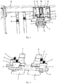
Fig. 1 is a schematic perspective structural diagram of an embodiment of a fluid cooling device according to the invention that is arranged on a battery storage rack. -
Fig. 2 is a schematic perspective structural diagram of a fluid cooling terminal unit of the embodiment of the fluid cooling device shown inFig. 1 . -
Fig.3 is a schematic perspective structural diagram of a first bracket, a second bracket, and a driving unit of the embodiment of the fluid cooling device shown inFig. 1 with the fluid cooling terminal unit being omitted. - First, it should be noted that the structures, compositions, features, and advantages of a fluid cooling device, a battery storage rack, and a battery operation platform of the invention will be specifically described below by way of example. However, all the descriptions are for the purpose of illustration only and should not be construed as limiting the invention in any way. The technical term "battery" as used herein includes, but is not limited to, a battery, a set of batteries, a battery pack, etc. used to power a vehicle.
- In addition, with respect to any single technical feature described or implied in the embodiments described herein, or any single technical feature shown or implied in the drawings, the invention further allows for any combination or deletion of these technical features (or equivalents thereof) to be made, to obtain still other additional embodiments of the invention which may not be directly mentioned herein. Additionally, in order to simplify the figures, the same or similar parts and features may only be marked at one or several places in one and the same figure.
- Referring to
Figs. 1 to 3 , these figures schematically show the basic structure and composition of one embodiment of a fluid cooling device according to the invention, which will be described in detail below. - In this given embodiment, the fluid cooling device is provided for cooling a battery located in a storage space of a battery storage rack, so as to reduce the substrate temperature of the battery, and to effectively control and reduce the heat accumulated inside the battery storage rack. As shown in
Fig. 1 , a battery to be charged and supplemented with energy is placed in a storage space of abattery storage rack 16. Such a battery may be a used battery that is unloaded from a vehicle by a battery swap operation device and then moved into the storage space of thebattery storage rack 16, and is recharged such that the battery is supplemented with power and restored, so that the battery can then be moved out of the storage space of thebattery storage rack 16 when needed and loaded into a vehicle with a battery needing to be swapped. It should be understood that the above-mentioned vehicle includes but is not limited to a battery electric vehicle, a hybrid battery vehicle, etc. - The fluid cooling device comprises a
first bracket 1, asecond bracket 2, a fluidcooling terminal unit 3, and adriving unit 4. Thefirst bracket 1 is installed on thebattery storage rack 16 by any suitable means such as bolt connection, and thebattery storage rack 16 may have a single-sided cantilever structure in order to simplify the structure and increase the space utilization, and it is also possible to provide components such as a sensor, a cable and a fluid pipeline on thebattery storage rack 16, so as to facilitate daily equipment operation, maintenance and overhaul. - As shown in
Fig. 1 , thesecond bracket 2 and thefirst bracket 1 are arranged adjacent to each other, and the fluidcooling terminal unit 3 is mounted on thesecond bracket 2, such that thesecond bracket 2 can be driven by thedriving unit 4 to move relative to thefirst bracket 1, so as to cause the fluid cooling device to engage with a corresponding connector of the battery to be charged to transfer fluid (for example, various suitable liquids or gases such as water) to the corresponding connector to achieve the cooling and temperature-reducing effect, or to cause the fluid cooling device to disengage from the corresponding connector, or an inlet or an outlet of the battery if there is no need to continue cooling the battery (such as the battery has been fully charged). - Specifically, referring to
Figs. 1 to 3 , the fluidcooling terminal unit 3 is provided with afirst connector 6, asecond connector 7, athird connector 8, and afourth connector 9, wherein thefirst connector 6 and thesecond connector 7 remain in fluid communication with each other, and thethird connector 8 and thefourth connector 9 remain in fluid communication with each other; and thefirst connector 6 may be connected to anoutput port 13 of apipeline 15 for supplying a cooling fluid via a connecting component such as a flexible pipe to form a fluid flow path, and thethird connector 8 may be similarly connected to aninput port 14 of thepipeline 15 via a connecting component such as a flexible pipe. - The
second connector 7 and thefourth connector 9 are respectively configured to match a fluid inlet and a fluid outlet provided on the rechargeable battery respectively, such that a communication pipeline can be detachably formed. That is to say, under the driving action of thedriving unit 4, thesecond connector 7 may be engaged with the fluid inlet on the rechargeable battery to communicate with each other, and thefourth connector 9 may be engaged with the fluid outlet on the rechargeable battery to communicate with each other, so that a fluid circulation circuit in which fluid sequentially flows from theoutput port 13 of thepipeline 15 through thefirst connector 6, thesecond connector 7, and the fluid inlet of the battery to an internal flow pipeline of the battery, and then flows out from the fluid outlet of the battery back to thepipeline 15 through thefourth connector 9, thethird connector 8 and theinput port 14 is formed. By providing the above-mentioned fluid circulation circuit, heat exchange can be performed with the battery to carry the heat energy generated during charging, thereby effectively realizing the purposes such as eliminating or avoiding heat accumulation, and reducing the temperature of the battery and its surrounding environment space. - In an optional case, the
first connector 6 and/or thethird connector 8 may be configured to rotate within a certain angle range in a circumferential direction (this can be pre-designed according to specific application requirements). Providing such a degree of freedom of spatial rotation is not only convenient for practical operation, but also very beneficial to protect components such as the connectors, and connecting pipes, so that the components are durable and are not likely to be damaged to cause outward fluid leakage, which can improve the safety and reliability of the system. - A perspective structure of the fluid
cooling terminal unit 3 of this embodiment is schematically and generally shown inFig. 2 . In this embodiment of the fluid cooling device, the fluidcooling terminal unit 3 is optionally configured to comprise two parts, namely, afirst part 5 connected to thesecond bracket 2 and asecond part 10 connected to the first part and therefore thesecond bracket 2. The reason for adopting this structural arrangement is that thesecond part 10 may be further preferably configured to have such degrees of freedom that not only can thesecond part 10 float on a horizontal plane relative to thefirst part 5, but can also perform a twisting movement, so that the complexity and manufacturing and maintenance costs of the device itself can be greatly reduced. Especially in the case of a certain deflection positioning error in the fluid inlet and/or the fluid outlet of the battery, thesecond connector 7 and thefourth connector 9 arranged on thesecond part 10 can be respectively very accurately engaged with the fluid inlet and the fluid outlet on the battery respectively, or the connectors and the corresponding inlet and the outlet are disengaged from the previously engaged state. - As an exemplary illustration, the above-mentioned degrees of freedom of spatial movements can be achieved by arranging some elastic components such as springs on the
second part 10 of the fluid coolingterminal unit 3. For example, as shown inFigs. 2 and3 , fourelastic components 11 may be optionally arranged on thesecond part 10, that is, opposite ends of thesecond part 10 are each provided with twoelastic components 11, and thefirst part 5 is configured to have a connecting rod member mounted on the top of eachelastic component 11, these connecting rod members passing through mountingholes 17 in thesecond bracket 2 and being screwed to thesecond bracket 2 with connectingmembers 18. As such, thesecond part 10 of the fluid coolingterminal unit 3 can be elastically supported by the elastic forces provided by theseelastic components 11. With the exemplary structural arrangement described above, thesecond part 10 can be floated on the horizontal plane relative to thefirst part 5 and can be twisted, so that a self-return function is provided to realize a safe and reliable engagement or disengagement operation between thesecond connector 7 and thefourth connector 9 and the fluid inlet and the fluid outlet of the battery, that is, an insertion/withdrawal operation. - The driving
unit 4 is used as a power part of the fluid cooling device to provide a driving force so as to realize the engagement or disengagement operation between the connectors of the fluid coolingterminal unit 3 and the fluid inlet and the fluid outlet of the battery. - For example, in the case of light load, as shown in
Fig. 3 , oneair cylinder 20 and twolinear bearings 19 may be provided to realize the above function of thedriving unit 4. Specifically, theair cylinder 20 may be arranged on thefirst bracket 1 and the twolinear bearings 19 may be arranged on two sides of theair cylinder 20 respectively. The twolinear bearings 19 are used to movably support twoguide members 12 correspondingly provided on thesecond bracket 2. When theair cylinder 20 is activated to provide a driving force pneumatically such that thesecond bracket 2 moves relative to thefirst bracket 1, by means of thelinear bearings 19 and theguide members 12, it is possible to restrain a relative movement trajectory between thesecond bracket 2 and the first bracket 1 (that is, the perpendicularity of insertion/withdrawal of the connector) as expected, thereby ensuring a reliable engagement or disengagement operation between thesecond connector 7 and thefourth connector 9 of the fluid coolingterminal unit 3 and the fluid inlet and the fluid outlet on the battery respectively. - In addition, in the case of heavy load, it may also be contemplated that two
air cylinders 20 are used at the same time, which are arranged on two sides of thefirst bracket 1, so that it is possible to achieve the insertion/withdrawal operation between thesecond connector 7 and thefourth connector 9 of the fluid coolingterminal unit 3 and the fluid inlet and the fluid outlet of the battery respectively with a greater driving force. Of course, it should also be understood that the above-mentioned specifically set number and arrangement positions of thelinear bearings 19 are allowed to be flexibly selected and adjusted according to actual applications without departing from the spirit of the invention. - As yet another example, an electric motor driving approach can also be used to realize the function of the
driving unit 4, which can be used in the case of light load, etc. Specifically, an electric motor may be installed on thefirst bracket 1 to provide the driving force required by the drivingunit 4, and a linear guide rail may also be installed on thefirst bracket 1. Such a linear guide rail is used to movably support a guide member correspondingly provided on thesecond bracket 2, that is, when the electric motor is activated to operate to provide the driving force such that thesecond bracket 2 moves relative to thefirst bracket 1, by means of the linear guide rail and the guide member on thesecond bracket 2, it is possible to restrain a relative movement trajectory between thesecond bracket 2 and the first bracket 1 (that is, the perpendicularity of insertion/withdrawal of the connector) as expected, thereby ensuring a reliable engagement or disengagement operation between thesecond connector 7 and thefourth connector 9 of the fluid coolingterminal unit 3 and the fluid inlet and the fluid outlet on the battery respectively. - As described above, the invention provides a fluid cooling device with a compact structure, which is not only easy to assemble, use, repair and maintain, has low costs and is reliable in functional operation, but can also effectively realize the accurate, reliable and safe insertion/withdrawal operation on the fluid inlet and the fluid outlet of the battery terminal located in the battery storage rack, so that while energy supplement and power storage of the battery are efficiently completed, the temperature of the rechargeable battery and its surrounding environment is significantly reduced by means of an effective fluid circulation cooling treatment, thereby facilitating in ensuring the performance of the battery and prolonging the life of the battery. The use of the technical solution provided by the invention has positive effects for the further promotion of the use of new energy vehicles, the promotion of environmental protection, etc.
- According to another technical solution of the invention, there is also provided a battery storage rack having one or more storage spaces for storing batteries. The fluid cooling device designed and provided according to the invention may be provided in each storage space of such a battery storage rack, so as to give full play to the obvious technical advantages as described above provided by the solution of the invention.
- In addition, according to yet another technical solution of the invention, there is also provided a battery operation platform. One or more battery storage racks designed and provided above according to the invention may be provided on the battery operation platform, such that such battery storage racks are provided to store batteries and charge and supplement same with energy, and the fluid cooling device designed and provided by the invention can be also used to safely and reliably cool these batteries and reduce the temperature thereof. It should be understood that the operations that can be achieved by the battery operation platform include, but are not limited to, battery swap, charging, and monitoring of battery information (such as state of charge, health level, number of uses, etc. of a battery), and after completing the charging and energy supplement, the vehicle battery can be loaded into various types of new energy vehicles such as battery electric vehicles and hybrid electric vehicles, and put into use.
- The fluid cooling device, the battery storage rack, and the battery operation platform according to the invention are merely illustrated in detail as above by way of example. These examples are for the purpose of illustrating the principle of the invention and the implementations thereof only, rather than limiting the invention. Those skilled in the art can make various variations and improvements without departing from the spirit and scope of the invention. Therefore, all equivalent technical solutions should fall within the scope of the invention and be defined by the claims of the invention.
Claims (12)
- A fluid cooling device for cooling a battery located in a storage space of a battery storage rack, characterized by comprising:a first bracket mounted on the battery storage rack;a fluid cooling terminal unit provided with a first connector and a second connector in fluid communication with each other, and a third connector and a fourth connector in fluid communication with each other, the first connector and the third connector being respectively in communication with an output port and an input port of a pipeline for supplying a fluid;a second bracket arranged adjacent to the first bracket, the fluid cooling terminal unit being mounted on the second bracket; anda driving unit configured for providing a driving force to move the first bracket and the second bracket relative to each other so as to cause the second connector and the fourth connector to engage with a fluid inlet and a fluid outlet provided on the battery respectively to form a fluid circulation circuit for cooling the battery, or to cause the second connector and the fourth connector to disengage from the fluid inlet and the fluid outlet respectively.
- The fluid cooling device according to claim 1, characterized in that the fluid cooling terminal unit comprises:a first part connected to the second bracket; anda second part provided with the first connector, the second connector, the third connector, and the fourth connector, wherein the second part is connected to the first part and is configured to have degrees of freedom of floating on a horizontal plane relative to the first part and of twisting.
- The fluid cooling device according to claim 2, characterized in that opposite ends of the second part are each provided with two elastic components, and the first part comprises a connecting rod member mounted on the top of each elastic component and screwed to the second bracket.
- The fluid cooling device according to claim 2, characterized in that the first connector and/or the third connector is arranged to be rotatable in a circumferential direction.
- The fluid cooling device according to claim 1, characterized in that the first connector communicates with the output port via a flexible pipe, and the third connector communicates with the input port via a flexible pipe.
- The fluid cooling device according to any one of claims 1-5, characterized in that the driving unit comprises at least one air cylinder and at least two linear bearings, the air cylinder is installed on the first bracket for providing the driving force, and the linear bearings are installed on the first bracket for movably supporting guide members correspondingly provided on the second bracket.
- The fluid cooling device according to claim 6, characterized in that two air cylinders are provided, which are arranged on two sides of the first bracket, respectively.
- The fluid cooling device according to any one of claims 1-5, characterized in that the driving unit comprises an electric motor and a linear guide rail, the electric motor is installed on the first bracket for providing the driving force, and the linear guide rail is installed on the first bracket for movably supporting a guide member correspondingly provided on the second bracket.
- The fluid cooling device according to any one of claims 1-5, characterized in that the battery storage rack is configured as a single-sided cantilever structure.
- The fluid cooling device according to any one of claims 1-5, characterized in that a part of the pipeline is mounted on the battery storage rack, and the fluid is water.
- A battery storage rack, characterized by comprising one or more storage spaces for storing batteries, each storage space being provided with a fluid cooling device according to any one of claims 1-10.
- A battery operation platform, characterized in that the battery operation platform is provided with one or more battery storage racks according to claim 11.
Applications Claiming Priority (2)
| Application Number | Priority Date | Filing Date | Title |
|---|---|---|---|
| CN201820281714.8U CN208232844U (en) | 2018-02-28 | 2018-02-28 | Fluid cooling device, battery storage rack and battery operation platform |
| PCT/CN2018/091585 WO2019165727A1 (en) | 2018-02-28 | 2018-06-15 | Fluid cooling device, battery storage rack and battery operating platform |
Publications (3)
| Publication Number | Publication Date |
|---|---|
| EP3760464A1 true EP3760464A1 (en) | 2021-01-06 |
| EP3760464A4 EP3760464A4 (en) | 2021-09-22 |
| EP3760464B1 EP3760464B1 (en) | 2023-02-22 |
Family
ID=64587816
Family Applications (1)
| Application Number | Title | Priority Date | Filing Date |
|---|---|---|---|
| EP18907808.2A Active EP3760464B1 (en) | 2018-02-28 | 2018-06-15 | Battery storage rack and battery operating platform |
Country Status (3)
| Country | Link |
|---|---|
| EP (1) | EP3760464B1 (en) |
| CN (1) | CN208232844U (en) |
| WO (1) | WO2019165727A1 (en) |
Families Citing this family (1)
| Publication number | Priority date | Publication date | Assignee | Title |
|---|---|---|---|---|
| CN111063962B (en) * | 2019-12-23 | 2025-07-11 | 珠海泰坦新动力电子有限公司 | A temperature control system and method based on chemical composition and content system |
Family Cites Families (7)
| Publication number | Priority date | Publication date | Assignee | Title |
|---|---|---|---|---|
| FR2946220B1 (en) * | 2009-05-29 | 2011-05-20 | Peugeot Citroen Automobiles Sa | ELECTRIC POWER TRANSFER DEVICE FOR MOTOR VEHICLE AND ELECTRIC OR PARTIALLY ELECTRIC VEHICLE EQUIPPED WITH SUCH A DEVICE |
| JP2013069739A (en) * | 2011-09-21 | 2013-04-18 | Toyota Motor Corp | Semiconductor unit and manufacturing method thereof |
| CN202773236U (en) * | 2012-08-08 | 2013-03-06 | 吴江市博众精工科技有限公司 | Cooling module |
| JP6135543B2 (en) * | 2014-02-19 | 2017-05-31 | 株式会社デンソー | Power supply |
| DE102015207666A1 (en) * | 2015-04-27 | 2016-10-27 | Bayerische Motoren Werke Aktiengesellschaft | Battery module and high-voltage storage |
| CN105633505A (en) * | 2016-03-18 | 2016-06-01 | 重庆长安汽车股份有限公司 | Power battery liquid-cooling apparatus |
| CN208112271U (en) * | 2018-02-28 | 2018-11-16 | 蔚来汽车有限公司 | Battery charging units, battery storage racks and battery operating platforms |
-
2018
- 2018-02-28 CN CN201820281714.8U patent/CN208232844U/en active Active
- 2018-06-15 EP EP18907808.2A patent/EP3760464B1/en active Active
- 2018-06-15 WO PCT/CN2018/091585 patent/WO2019165727A1/en not_active Ceased
Also Published As
| Publication number | Publication date |
|---|---|
| EP3760464A4 (en) | 2021-09-22 |
| CN208232844U (en) | 2018-12-14 |
| EP3760464B1 (en) | 2023-02-22 |
| WO2019165727A1 (en) | 2019-09-06 |
Similar Documents
| Publication | Publication Date | Title |
|---|---|---|
| WO2019047476A1 (en) | Charging container | |
| CN103531502B (en) | A kind of workpiece table device | |
| CN217589113U (en) | Split type energy storage device | |
| CN209472019U (en) | Energy storage device | |
| CN103792935A (en) | Function test system applied to automobile electronic control unit and control method thereof | |
| EP3760464A1 (en) | Fluid cooling device, battery storage rack and battery operating platform | |
| EP3761474A1 (en) | Battery charging device, battery storage frame and battery operation platform | |
| JP7392201B2 (en) | Uninterruptible power supply for submarine applications | |
| CN119381634B (en) | A subsea energy storage control system | |
| CN221509213U (en) | Auxiliary control power cabinet for energy storage and liquid cooling container energy storage system thereof | |
| KR102889661B1 (en) | Mounting system | |
| CN111864301A (en) | A water distribution device for battery cooling system of battery swapping station | |
| CN218827454U (en) | A liquid-cooled, heat-radiating and energy-storage integrated cabinet structure | |
| US20160218405A1 (en) | Use of High-Temperature Batteries for Ships | |
| CN113054287B (en) | Battery pack heating system, charging box, battery swap station and energy storage station | |
| CN113043873B (en) | Charging unit temperature regulation system, charging box, power conversion station and energy storage station | |
| CN118472496B (en) | Battery for improving endurance of electric vehicle | |
| CN201081844Y (en) | Proton exchange membrane fuel cell serving as emergency power supply system for transformer substation | |
| CN203466624U (en) | A magnetic levitation flywheel energy storage uninterruptible power supply vehicle | |
| CN221579531U (en) | Charging racks, batteries, power devices and battery replacement systems | |
| CN223437305U (en) | A 5G BBU single-phase immersion liquid cooling cabinet | |
| CN112038519A (en) | Self-cooling energy storage cabinet | |
| TWM599477U (en) | Smart internal circulation heat dissipation device of lithium battery | |
| CN217694119U (en) | AGV electrical power generating system that low temperature performance is good and stable | |
| CN224138204U (en) | Energy storage devices, energy storage systems and charging networks |
Legal Events
| Date | Code | Title | Description |
|---|---|---|---|
| STAA | Information on the status of an ep patent application or granted ep patent |
Free format text: STATUS: THE INTERNATIONAL PUBLICATION HAS BEEN MADE |
|
| PUAI | Public reference made under article 153(3) epc to a published international application that has entered the european phase |
Free format text: ORIGINAL CODE: 0009012 |
|
| STAA | Information on the status of an ep patent application or granted ep patent |
Free format text: STATUS: REQUEST FOR EXAMINATION WAS MADE |
|
| 17P | Request for examination filed |
Effective date: 20200928 |
|
| AK | Designated contracting states |
Kind code of ref document: A1 Designated state(s): AL AT BE BG CH CY CZ DE DK EE ES FI FR GB GR HR HU IE IS IT LI LT LU LV MC MK MT NL NO PL PT RO RS SE SI SK SM TR |
|
| AX | Request for extension of the european patent |
Extension state: BA ME |
|
| RIN1 | Information on inventor provided before grant (corrected) |
Inventor name: QI, WENGANG Inventor name: YANG, CHAO Inventor name: ZHAO, ZHILING Inventor name: HAO, ZHANDUO |
|
| DAV | Request for validation of the european patent (deleted) | ||
| DAX | Request for extension of the european patent (deleted) | ||
| A4 | Supplementary search report drawn up and despatched |
Effective date: 20210820 |
|
| RIC1 | Information provided on ipc code assigned before grant |
Ipc: H01M 50/00 20210101ALI20210816BHEP Ipc: B60K 1/00 20060101ALI20210816BHEP Ipc: B60K 11/02 20060101ALI20210816BHEP Ipc: B60K 1/04 20190101ALI20210816BHEP Ipc: F25D 1/02 20060101ALI20210816BHEP Ipc: B60S 5/06 20190101ALI20210816BHEP Ipc: B60K 11/00 20060101AFI20210816BHEP |
|
| REG | Reference to a national code |
Ref country code: DE Ref legal event code: R079 Ref document number: 602018046566 Country of ref document: DE Free format text: PREVIOUS MAIN CLASS: B60K0011000000 Ipc: B60K0001040000 |
|
| RIC1 | Information provided on ipc code assigned before grant |
Ipc: H01M 50/249 20210101ALN20220701BHEP Ipc: H01M 10/6568 20140101ALN20220701BHEP Ipc: H01M 10/613 20140101ALN20220701BHEP Ipc: F25D 1/02 20060101ALN20220701BHEP Ipc: B60S 5/06 20190101ALN20220701BHEP Ipc: H01M 50/00 20210101ALN20220701BHEP Ipc: B60K 11/02 20060101ALN20220701BHEP Ipc: B60K 11/00 20060101ALN20220701BHEP Ipc: B60K 1/00 20060101ALN20220701BHEP Ipc: B60K 1/04 20190101AFI20220701BHEP |
|
| GRAP | Despatch of communication of intention to grant a patent |
Free format text: ORIGINAL CODE: EPIDOSNIGR1 |
|
| STAA | Information on the status of an ep patent application or granted ep patent |
Free format text: STATUS: GRANT OF PATENT IS INTENDED |
|
| INTG | Intention to grant announced |
Effective date: 20220831 |
|
| GRAS | Grant fee paid |
Free format text: ORIGINAL CODE: EPIDOSNIGR3 |
|
| GRAA | (expected) grant |
Free format text: ORIGINAL CODE: 0009210 |
|
| STAA | Information on the status of an ep patent application or granted ep patent |
Free format text: STATUS: THE PATENT HAS BEEN GRANTED |
|
| AK | Designated contracting states |
Kind code of ref document: B1 Designated state(s): AL AT BE BG CH CY CZ DE DK EE ES FI FR GB GR HR HU IE IS IT LI LT LU LV MC MK MT NL NO PL PT RO RS SE SI SK SM TR |
|
| REG | Reference to a national code |
Ref country code: GB Ref legal event code: FG4D |
|
| REG | Reference to a national code |
Ref country code: CH Ref legal event code: EP |
|
| REG | Reference to a national code |
Ref country code: AT Ref legal event code: REF Ref document number: 1549295 Country of ref document: AT Kind code of ref document: T Effective date: 20230315 Ref country code: IE Ref legal event code: FG4D |
|
| REG | Reference to a national code |
Ref country code: DE Ref legal event code: R096 Ref document number: 602018046566 Country of ref document: DE |
|
| REG | Reference to a national code |
Ref country code: LT Ref legal event code: MG9D |
|
| REG | Reference to a national code |
Ref country code: NL Ref legal event code: MP Effective date: 20230222 |
|
| REG | Reference to a national code |
Ref country code: AT Ref legal event code: MK05 Ref document number: 1549295 Country of ref document: AT Kind code of ref document: T Effective date: 20230222 |
|
| PG25 | Lapsed in a contracting state [announced via postgrant information from national office to epo] |
Ref country code: RS Free format text: LAPSE BECAUSE OF FAILURE TO SUBMIT A TRANSLATION OF THE DESCRIPTION OR TO PAY THE FEE WITHIN THE PRESCRIBED TIME-LIMIT Effective date: 20230222 Ref country code: PT Free format text: LAPSE BECAUSE OF FAILURE TO SUBMIT A TRANSLATION OF THE DESCRIPTION OR TO PAY THE FEE WITHIN THE PRESCRIBED TIME-LIMIT Effective date: 20230622 Ref country code: NO Free format text: LAPSE BECAUSE OF FAILURE TO SUBMIT A TRANSLATION OF THE DESCRIPTION OR TO PAY THE FEE WITHIN THE PRESCRIBED TIME-LIMIT Effective date: 20230522 Ref country code: NL Free format text: LAPSE BECAUSE OF FAILURE TO SUBMIT A TRANSLATION OF THE DESCRIPTION OR TO PAY THE FEE WITHIN THE PRESCRIBED TIME-LIMIT Effective date: 20230222 Ref country code: LV Free format text: LAPSE BECAUSE OF FAILURE TO SUBMIT A TRANSLATION OF THE DESCRIPTION OR TO PAY THE FEE WITHIN THE PRESCRIBED TIME-LIMIT Effective date: 20230222 Ref country code: LT Free format text: LAPSE BECAUSE OF FAILURE TO SUBMIT A TRANSLATION OF THE DESCRIPTION OR TO PAY THE FEE WITHIN THE PRESCRIBED TIME-LIMIT Effective date: 20230222 Ref country code: HR Free format text: LAPSE BECAUSE OF FAILURE TO SUBMIT A TRANSLATION OF THE DESCRIPTION OR TO PAY THE FEE WITHIN THE PRESCRIBED TIME-LIMIT Effective date: 20230222 Ref country code: ES Free format text: LAPSE BECAUSE OF FAILURE TO SUBMIT A TRANSLATION OF THE DESCRIPTION OR TO PAY THE FEE WITHIN THE PRESCRIBED TIME-LIMIT Effective date: 20230222 Ref country code: AT Free format text: LAPSE BECAUSE OF FAILURE TO SUBMIT A TRANSLATION OF THE DESCRIPTION OR TO PAY THE FEE WITHIN THE PRESCRIBED TIME-LIMIT Effective date: 20230222 |
|
| PG25 | Lapsed in a contracting state [announced via postgrant information from national office to epo] |
Ref country code: SE Free format text: LAPSE BECAUSE OF FAILURE TO SUBMIT A TRANSLATION OF THE DESCRIPTION OR TO PAY THE FEE WITHIN THE PRESCRIBED TIME-LIMIT Effective date: 20230222 Ref country code: PL Free format text: LAPSE BECAUSE OF FAILURE TO SUBMIT A TRANSLATION OF THE DESCRIPTION OR TO PAY THE FEE WITHIN THE PRESCRIBED TIME-LIMIT Effective date: 20230222 Ref country code: IS Free format text: LAPSE BECAUSE OF FAILURE TO SUBMIT A TRANSLATION OF THE DESCRIPTION OR TO PAY THE FEE WITHIN THE PRESCRIBED TIME-LIMIT Effective date: 20230622 Ref country code: GR Free format text: LAPSE BECAUSE OF FAILURE TO SUBMIT A TRANSLATION OF THE DESCRIPTION OR TO PAY THE FEE WITHIN THE PRESCRIBED TIME-LIMIT Effective date: 20230523 Ref country code: FI Free format text: LAPSE BECAUSE OF FAILURE TO SUBMIT A TRANSLATION OF THE DESCRIPTION OR TO PAY THE FEE WITHIN THE PRESCRIBED TIME-LIMIT Effective date: 20230222 |
|
| PG25 | Lapsed in a contracting state [announced via postgrant information from national office to epo] |
Ref country code: SM Free format text: LAPSE BECAUSE OF FAILURE TO SUBMIT A TRANSLATION OF THE DESCRIPTION OR TO PAY THE FEE WITHIN THE PRESCRIBED TIME-LIMIT Effective date: 20230222 Ref country code: RO Free format text: LAPSE BECAUSE OF FAILURE TO SUBMIT A TRANSLATION OF THE DESCRIPTION OR TO PAY THE FEE WITHIN THE PRESCRIBED TIME-LIMIT Effective date: 20230222 Ref country code: EE Free format text: LAPSE BECAUSE OF FAILURE TO SUBMIT A TRANSLATION OF THE DESCRIPTION OR TO PAY THE FEE WITHIN THE PRESCRIBED TIME-LIMIT Effective date: 20230222 Ref country code: DK Free format text: LAPSE BECAUSE OF FAILURE TO SUBMIT A TRANSLATION OF THE DESCRIPTION OR TO PAY THE FEE WITHIN THE PRESCRIBED TIME-LIMIT Effective date: 20230222 Ref country code: CZ Free format text: LAPSE BECAUSE OF FAILURE TO SUBMIT A TRANSLATION OF THE DESCRIPTION OR TO PAY THE FEE WITHIN THE PRESCRIBED TIME-LIMIT Effective date: 20230222 |
|
| REG | Reference to a national code |
Ref country code: DE Ref legal event code: R097 Ref document number: 602018046566 Country of ref document: DE |
|
| PG25 | Lapsed in a contracting state [announced via postgrant information from national office to epo] |
Ref country code: SK Free format text: LAPSE BECAUSE OF FAILURE TO SUBMIT A TRANSLATION OF THE DESCRIPTION OR TO PAY THE FEE WITHIN THE PRESCRIBED TIME-LIMIT Effective date: 20230222 |
|
| PLBE | No opposition filed within time limit |
Free format text: ORIGINAL CODE: 0009261 |
|
| STAA | Information on the status of an ep patent application or granted ep patent |
Free format text: STATUS: NO OPPOSITION FILED WITHIN TIME LIMIT |
|
| PG25 | Lapsed in a contracting state [announced via postgrant information from national office to epo] |
Ref country code: MC Free format text: LAPSE BECAUSE OF FAILURE TO SUBMIT A TRANSLATION OF THE DESCRIPTION OR TO PAY THE FEE WITHIN THE PRESCRIBED TIME-LIMIT Effective date: 20230222 |
|
| 26N | No opposition filed |
Effective date: 20231123 |
|
| PG25 | Lapsed in a contracting state [announced via postgrant information from national office to epo] |
Ref country code: SI Free format text: LAPSE BECAUSE OF FAILURE TO SUBMIT A TRANSLATION OF THE DESCRIPTION OR TO PAY THE FEE WITHIN THE PRESCRIBED TIME-LIMIT Effective date: 20230222 Ref country code: MC Free format text: LAPSE BECAUSE OF FAILURE TO SUBMIT A TRANSLATION OF THE DESCRIPTION OR TO PAY THE FEE WITHIN THE PRESCRIBED TIME-LIMIT Effective date: 20230222 |
|
| REG | Reference to a national code |
Ref country code: CH Ref legal event code: PL |
|
| REG | Reference to a national code |
Ref country code: BE Ref legal event code: MM Effective date: 20230630 |
|
| PG25 | Lapsed in a contracting state [announced via postgrant information from national office to epo] |
Ref country code: LU Free format text: LAPSE BECAUSE OF NON-PAYMENT OF DUE FEES Effective date: 20230615 |
|
| REG | Reference to a national code |
Ref country code: IE Ref legal event code: MM4A |
|
| PG25 | Lapsed in a contracting state [announced via postgrant information from national office to epo] |
Ref country code: LU Free format text: LAPSE BECAUSE OF NON-PAYMENT OF DUE FEES Effective date: 20230615 |
|
| PG25 | Lapsed in a contracting state [announced via postgrant information from national office to epo] |
Ref country code: IE Free format text: LAPSE BECAUSE OF NON-PAYMENT OF DUE FEES Effective date: 20230615 |
|
| PG25 | Lapsed in a contracting state [announced via postgrant information from national office to epo] |
Ref country code: IE Free format text: LAPSE BECAUSE OF NON-PAYMENT OF DUE FEES Effective date: 20230615 Ref country code: CH Free format text: LAPSE BECAUSE OF NON-PAYMENT OF DUE FEES Effective date: 20230630 |
|
| PG25 | Lapsed in a contracting state [announced via postgrant information from national office to epo] |
Ref country code: IT Free format text: LAPSE BECAUSE OF FAILURE TO SUBMIT A TRANSLATION OF THE DESCRIPTION OR TO PAY THE FEE WITHIN THE PRESCRIBED TIME-LIMIT Effective date: 20230222 Ref country code: BE Free format text: LAPSE BECAUSE OF NON-PAYMENT OF DUE FEES Effective date: 20230630 |
|
| PG25 | Lapsed in a contracting state [announced via postgrant information from national office to epo] |
Ref country code: BG Free format text: LAPSE BECAUSE OF FAILURE TO SUBMIT A TRANSLATION OF THE DESCRIPTION OR TO PAY THE FEE WITHIN THE PRESCRIBED TIME-LIMIT Effective date: 20230222 |
|
| PG25 | Lapsed in a contracting state [announced via postgrant information from national office to epo] |
Ref country code: BG Free format text: LAPSE BECAUSE OF FAILURE TO SUBMIT A TRANSLATION OF THE DESCRIPTION OR TO PAY THE FEE WITHIN THE PRESCRIBED TIME-LIMIT Effective date: 20230222 |
|
| PGFP | Annual fee paid to national office [announced via postgrant information from national office to epo] |
Ref country code: DE Payment date: 20250618 Year of fee payment: 8 |
|
| PGFP | Annual fee paid to national office [announced via postgrant information from national office to epo] |
Ref country code: GB Payment date: 20250618 Year of fee payment: 8 |
|
| PGFP | Annual fee paid to national office [announced via postgrant information from national office to epo] |
Ref country code: FR Payment date: 20250626 Year of fee payment: 8 |
|
| PG25 | Lapsed in a contracting state [announced via postgrant information from national office to epo] |
Ref country code: CY Free format text: LAPSE BECAUSE OF FAILURE TO SUBMIT A TRANSLATION OF THE DESCRIPTION OR TO PAY THE FEE WITHIN THE PRESCRIBED TIME-LIMIT; INVALID AB INITIO Effective date: 20180615 |
|
| PG25 | Lapsed in a contracting state [announced via postgrant information from national office to epo] |
Ref country code: HU Free format text: LAPSE BECAUSE OF FAILURE TO SUBMIT A TRANSLATION OF THE DESCRIPTION OR TO PAY THE FEE WITHIN THE PRESCRIBED TIME-LIMIT; INVALID AB INITIO Effective date: 20180615 |
|
| PG25 | Lapsed in a contracting state [announced via postgrant information from national office to epo] |
Ref country code: TR Free format text: LAPSE BECAUSE OF FAILURE TO SUBMIT A TRANSLATION OF THE DESCRIPTION OR TO PAY THE FEE WITHIN THE PRESCRIBED TIME-LIMIT Effective date: 20230222 |