EP3760371A1 - Blocking and releasing device of panels to be worked and method of use thereof - Google Patents
Blocking and releasing device of panels to be worked and method of use thereof Download PDFInfo
- Publication number
- EP3760371A1 EP3760371A1 EP20180440.8A EP20180440A EP3760371A1 EP 3760371 A1 EP3760371 A1 EP 3760371A1 EP 20180440 A EP20180440 A EP 20180440A EP 3760371 A1 EP3760371 A1 EP 3760371A1
- Authority
- EP
- European Patent Office
- Prior art keywords
- blocking
- releasing device
- panel
- sacrificial
- sacrificial panel
- Prior art date
- Legal status (The legal status is an assumption and is not a legal conclusion. Google has not performed a legal analysis and makes no representation as to the accuracy of the status listed.)
- Granted
Links
Images
Classifications
-
- B—PERFORMING OPERATIONS; TRANSPORTING
- B23—MACHINE TOOLS; METAL-WORKING NOT OTHERWISE PROVIDED FOR
- B23Q—DETAILS, COMPONENTS, OR ACCESSORIES FOR MACHINE TOOLS, e.g. ARRANGEMENTS FOR COPYING OR CONTROLLING; MACHINE TOOLS IN GENERAL CHARACTERISED BY THE CONSTRUCTION OF PARTICULAR DETAILS OR COMPONENTS; COMBINATIONS OR ASSOCIATIONS OF METAL-WORKING MACHINES, NOT DIRECTED TO A PARTICULAR RESULT
- B23Q3/00—Devices holding, supporting, or positioning work or tools, of a kind normally removable from the machine
- B23Q3/02—Devices holding, supporting, or positioning work or tools, of a kind normally removable from the machine for mounting on a work-table, tool-slide, or analogous part
- B23Q3/06—Work-clamping means
- B23Q3/08—Work-clamping means other than mechanically-actuated
- B23Q3/088—Work-clamping means other than mechanically-actuated using vacuum means
-
- B—PERFORMING OPERATIONS; TRANSPORTING
- B23—MACHINE TOOLS; METAL-WORKING NOT OTHERWISE PROVIDED FOR
- B23Q—DETAILS, COMPONENTS, OR ACCESSORIES FOR MACHINE TOOLS, e.g. ARRANGEMENTS FOR COPYING OR CONTROLLING; MACHINE TOOLS IN GENERAL CHARACTERISED BY THE CONSTRUCTION OF PARTICULAR DETAILS OR COMPONENTS; COMBINATIONS OR ASSOCIATIONS OF METAL-WORKING MACHINES, NOT DIRECTED TO A PARTICULAR RESULT
- B23Q3/00—Devices holding, supporting, or positioning work or tools, of a kind normally removable from the machine
- B23Q3/18—Devices holding, supporting, or positioning work or tools, of a kind normally removable from the machine for positioning only
-
- B—PERFORMING OPERATIONS; TRANSPORTING
- B25—HAND TOOLS; PORTABLE POWER-DRIVEN TOOLS; MANIPULATORS
- B25B—TOOLS OR BENCH DEVICES NOT OTHERWISE PROVIDED FOR, FOR FASTENING, CONNECTING, DISENGAGING, OR HOLDING
- B25B11/00—Work holders not covered by any preceding group in the subclass, e.g. magnetic work holders, vacuum work holders
- B25B11/005—Vacuum work holders
-
- B—PERFORMING OPERATIONS; TRANSPORTING
- B23—MACHINE TOOLS; METAL-WORKING NOT OTHERWISE PROVIDED FOR
- B23Q—DETAILS, COMPONENTS, OR ACCESSORIES FOR MACHINE TOOLS, e.g. ARRANGEMENTS FOR COPYING OR CONTROLLING; MACHINE TOOLS IN GENERAL CHARACTERISED BY THE CONSTRUCTION OF PARTICULAR DETAILS OR COMPONENTS; COMBINATIONS OR ASSOCIATIONS OF METAL-WORKING MACHINES, NOT DIRECTED TO A PARTICULAR RESULT
- B23Q1/00—Members which are comprised in the general build-up of a form of machine, particularly relatively large fixed members
- B23Q1/03—Stationary work or tool supports
- B23Q1/037—Stationary work or tool supports comprising series of support elements whose relative distance is adjustable
Definitions
- the present invention relates to a blocking and releasing device of panels to be worked and method of use thereof.
- the invention relates to a device and a method of the type mentioned, studied and realized in particular for coupling at least one device, such as for example a suction cup, to a support panel, such as a sacrificial panel.
- the panels to be worked are positioned, during the working phases, on one or more suckers, in their turn arranged above a support panel and suitably spaced from each other to support each panel to be worked.
- This support panel (called in jargon “sacrificial panel”) is positioned on a respective working plane of a working machine.
- Said sacrificial panel such as an MDF panel ("Medium-Density-Fibreboard")
- MDF panel Medium-Density-Fibreboard
- breathable panel possibly equipped with a plurality of small holes.
- the presence of one or more suckers on the sacrificial panel allows to support the panel to be worked, keeping it in position and avoiding that the same panel moves during the working phases.
- suckers are held in position by means of a vacuum condition created below the sacrificial panel.
- the suction cups are generally arranged manually on the sacrificial panel by an operator.
- Another object of the invention is to provide a method which allows at least one blocking and releasing device to be coupled to a sacrificial panel quickly, effectively and with simple use.
- a further object of the invention is to provide a blocking and releasing device for panels to be worked, which can be removably coupled to a sacrificial panel, and which is blocked, in use, on said sacrificial panel.
- Another object of the invention is to provide a blocking and releasing device for panels to be machined, which can be coupled to a sacrificial panel which is highly reliable, relatively simple to manufacture, and at competitive costs when compared to the prior art.
- a blocking and releasing device for a workpiece, intended to be placed on a support or sacrificial panel, which has at least one opening
- said blocking and releasing device comprises a main body, having a supporting surface, on which said workpiece can be placed, and a bearing surface, intended to be placed on said support or sacrificial panel
- said blocking and releasing device being characterized in that it comprises at least one pin arranged on said bearing surface, which can be removably inserted into said at least one opening of said sacrificial panel, so that, when said pin is inserted into said opening, said main body is constrained to said sacrificial panel.
- said blocking a releasing device may comprise two pins arranged for orienting said blocking and releasing device on said sacrificial panel.
- said main body may have a recess communicating with said bearing surface, so that, when said at least one pin is coupled with said at least one opening of said sacrificial panel, said blocking and releasing device is capable of holding said workpiece by means of a vacuum condition generated between said working plane and said sacrificial panel.
- said at least one pin may have a circular or polygonal section.
- said at least one blocking and releasing device may be a suction cup or a vice.
- said sacrificial panel may be breathable, and in that it comprises, after said step C, the following further step: D. creating, between said sacrificial panel and said working plane, a vacuum condition so as to keep in position said workpiece on said at least one suction cup or vice.
- the machine for working panels and the like substantially comprises a working plane 1, a working bridge 1', movable along the working plane 1, suitably equipped with means for carrying out workings, two sacrificial panels 2, arranged on said working plane 1, and four blocking and releasing devices 3, for fixing the panels to be worked (not shown in the figures).
- the working plane 1 of the machine M preferably develops longitudinally along the direction of the Cartesian axis X. Furthermore, said working plane 1 is configured to support said sacrificial panels 2 during the working phases.
- These sacrificial panels 2 are capable of supporting the elements to be worked, such as for example panels, beams and the like, both in case of they are positioned directly on the surface of the sacrificial panels 2, and in case of these elements to be worked are separated from said sacrificial panels 2 by means of said blocking and releasing devices 3, as described below.
- sacrificial panels 2 there are two sacrificial panels 2, however in further embodiments such sacrificial panels 2 can be in a number different from two, for example even one.
- Said blocking and releasing devices 3 are configured for gripping (and subsequently for releasing) the panels to be machined.
- each sacrificial panel 2 depends on the size of the respective panel to be worked.
- only one blocking and releasing device 3 can be used.
- these blocking and releasing devices 3 allow to retain each panel to be worked during the working phases.
- suitable means not shown, which the machine M is equipped with, a vacuum condition can be created between said working plane 1 and said sacrificial panel 2.
- these blocking and releasing devices 3 also allow to release said panel to be worked at the end of the working.
- said blocking and releasing devices are suckers 3.
- said blocking and releasing devices 3 can be clamps.
- said suckers 3 substantially comprise a main body 30 and two pins 32.
- These pins 32 can be, for example, inserted each in a respective seat 33 obtained in said main body 30.
- said pins 32 can also be made in one piece, or integral with said main body 30.
- the main body 30 according to the present invention is hollow and has a square section. However, in further embodiments said main body 30 can have, for example, a circular or rectangular section.
- Said main body 30 comprises a bearing surface 301, on which said panel to be worked can rest, and a bearing surface 302, intended to rest on said sacrificial panel 2.
- Said main body 30 comprises a cavity 31 communicating with said bearing surface 302, such that, when a vacuum condition is generated between said working plane 1 and said sacrificial panel 2, said sucker 3 is capable of retaining said panel to be worked placed on it.
- said pins 32 have a cylindrical cross section, and, as said, are installed in said respective seats 33 formed on said bearing surface 302.
- said pins 32 can have, for example, a polygonal section.
- said pins 32 are arranged to orient said blocking and releasing device 3 on said sacrificial panel 2, for example on the basis of the different types of workpiece working.
- said pins 32 are arranged substantially in the intermediate point of two opposite sides of said bearing surface 302.
- said pins 32 comprise a first end inserted inside said seats 33, and a second end, opposite the first end, which protrudes from each seat 33 by about 3 millimeters.
- two holes or openings 20 are made on the sacrificial panel 2 by means of a working tool, i.e. by means of a tip or a mill included in said machine M. These holes 20 can have a depth of about 4 millimeters.
- each pin 32 can be coupled to respective holes 20 made on said sacrificial panel 2 by suitable processing tools (not shown), included in said machine M.
- said pins 32 of each sucker 3 can be coupled, in use, to respective holes 20 of said sacrificial panel 2 so as to block, during the processing of said panel to be worked, each sucker 3 on said sacrificial panel 2.
- said holes 20 have a section compatible with said respective pins 32.
- the realization of the positioning holes 20 are carried out, as anticipated, by working tools in predetermined positions.
- the latter can be chosen by an operator or by means of a logic control unit connected to said machine M.
- a single pin 32 arranged in an eccentric position, but having a non-circular section, for example an elongated one.
- the machining tool of the machine M will have to make a groove on the sacrificial panel having a shape similar to the aforementioned section of said pin 32.
- the blocking and releasing device 3 it is also possible to provide a plurality of pins 32, for example three pins or four pins, arranged according to the most convenient configurations, aimed at fixing in a more stable manner said blocking and releasing device 3 on the sacrificial panel.
- the machine M will have to make a number of holes 20 corresponding to that of said pins 32.
- An advantage of the blocking and releasing device for panels to be machined which can be coupled to a panel according to the present invention is that of allowing a quick, effective and easy-to-use coupling.
- Another advantage of the blocking and releasing device for panels to be machined which can be coupled to a panel according to the present invention is that of allowing a removable coupling to a sacrificial panel.
Landscapes
- Engineering & Computer Science (AREA)
- Mechanical Engineering (AREA)
- Jigs For Machine Tools (AREA)
- Clamps And Clips (AREA)
Abstract
Description
- The present invention relates to a blocking and releasing device of panels to be worked and method of use thereof.
- More specifically, the invention relates to a device and a method of the type mentioned, studied and realized in particular for coupling at least one device, such as for example a suction cup, to a support panel, such as a sacrificial panel.
- In the following the description will refer to the coupling of suction cups to a panel, but it is clear that the same should not be considered limited to this specific use.
- As is known, there are currently machines for working wood panels, wooden beams, and the like.
- Typically, the panels to be worked are positioned, during the working phases, on one or more suckers, in their turn arranged above a support panel and suitably spaced from each other to support each panel to be worked.
- This support panel (called in jargon "sacrificial panel") is positioned on a respective working plane of a working machine.
- The description below will refer to the support panel with the expression "sacrificial panel".
- Said sacrificial panel, such as an MDF panel ("Medium-Density-Fibreboard"), is usually a breathable panel, possibly equipped with a plurality of small holes.
- As said, the presence of one or more suckers on the sacrificial panel allows to support the panel to be worked, keeping it in position and avoiding that the same panel moves during the working phases.
- In particular, said suckers are held in position by means of a vacuum condition created below the sacrificial panel.
- The suction cups are generally arranged manually on the sacrificial panel by an operator.
- One of the main drawbacks of these known solutions consists in the fact that the suckers, after being positioned, can move with respect to the assigned position.
- In this case, if the suction cups were accidentally moved from the assigned operating position, following the application of the vacuum for their fixing to the sacrificial panel, there would be a risk, for example in the case of a process that involves drilling the panel placed above said suction cups, to damage the suction cups themselves by means of the working tool.
- Furthermore, always in case of accidental incorrect positioning, it is necessary to carry out interventions by the operators, with the consequent downtime. This unavoidably causes an increase in costs for working the panels and the like.
- In light of the above, it is therefore an object of the present invention providing a blocking and releasing device for panels to be machined which can be coupled to a sacrificial panel, which overcomes the disadvantages of the known systems described above.
- Another object of the invention is to provide a method which allows at least one blocking and releasing device to be coupled to a sacrificial panel quickly, effectively and with simple use.
- A further object of the invention is to provide a blocking and releasing device for panels to be worked, which can be removably coupled to a sacrificial panel, and which is blocked, in use, on said sacrificial panel.
- Another object of the invention is to provide a blocking and releasing device for panels to be machined, which can be coupled to a sacrificial panel which is highly reliable, relatively simple to manufacture, and at competitive costs when compared to the prior art.
- It is therefore a specific object of the present invention a blocking and releasing device for a workpiece, intended to be placed on a support or sacrificial panel, which has at least one opening, wherein said blocking and releasing device comprises a main body, having a supporting surface, on which said workpiece can be placed, and a bearing surface, intended to be placed on said support or sacrificial panel, said blocking and releasing device being characterized in that it comprises at least one pin arranged on said bearing surface, which can be removably inserted into said at least one opening of said sacrificial panel, so that, when said pin is inserted into said opening, said main body is constrained to said sacrificial panel.
- In particular, according to the invention, said blocking a releasing device may comprise two pins arranged for orienting said blocking and releasing device on said sacrificial panel.
- Further according to the invention, said main body may have a recess communicating with said bearing surface, so that, when said at least one pin is coupled with said at least one opening of said sacrificial panel, said blocking and releasing device is capable of holding said workpiece by means of a vacuum condition generated between said working plane and said sacrificial panel.
- Finally, according to the invention, said at least one pin may have a circular or polygonal section.
- It is further object of the present invention a method for positioning a blocking and releasing device for a workpiece on a sacrificial panel, wherein said sacrificial panel is arranged on a working plane of a machine for working wood panels and the like, wherein said method comprises the following steps: A. providing at least one blocking and releasing device according to any one of the preceding claims; B. making at least one number of openings on said sacrificial panel corresponding to the number of pins of said blocking and releasing device, wherein said openings have a section compatible with said pins, in correspondence with a predetermined position; and C. placing said at least one blocking and releasing device in correspondence of said at least one number of openings so that, in use, each pin is inserted into a corresponding opening.
- In particular according to the invention, said at least one blocking and releasing device may be a suction cup or a vice.
- Finally, according to the invention, said sacrificial panel may be breathable, and in that it comprises, after said step C, the following further step: D. creating, between said sacrificial panel and said working plane, a vacuum condition so as to keep in position said workpiece on said at least one suction cup or vice.
- The present invention will be now described, for illustrative but not limitative purposes, according to its preferred embodiments, with particular reference to the figures of the enclosed drawings, wherein:
-
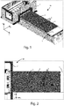
figure 1 shows a perspective view of a machine comprising a sacrificial panel, on which a plurality of blocking and releasing devices are arranged, according to the method of the present invention; -
figure 2 shows a top view of the machine offigure 1 ; -
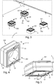
figure 3 shows, in detail, the coupling of the blocking and releasing device to the sacrificial panel, according tofigure 1 ; -
figure 4 illustrates a first perspective view of the blocking and releasing device according to the present invention; and -
figure 5 shows a second perspective view of the blocking and releasing device offigure 4 . - In the various figures, similar parts will be indicated by the same reference numbers.
- With reference to
figures 1 and 2 , the machine for working panels and the like, indicated with the reference letter M, substantially comprises a workingplane 1, a working bridge 1', movable along the workingplane 1, suitably equipped with means for carrying out workings, twosacrificial panels 2, arranged on said workingplane 1, and four blocking and releasingdevices 3, for fixing the panels to be worked (not shown in the figures). - In particular, the
working plane 1 of the machine M according to the present invention preferably develops longitudinally along the direction of the Cartesian axis X. Furthermore, said workingplane 1 is configured to support saidsacrificial panels 2 during the working phases. - These
sacrificial panels 2 are capable of supporting the elements to be worked, such as for example panels, beams and the like, both in case of they are positioned directly on the surface of thesacrificial panels 2, and in case of these elements to be worked are separated from saidsacrificial panels 2 by means of said blocking and releasingdevices 3, as described below. - As anticipated, in the described embodiment, there are two
sacrificial panels 2, however in further embodiments suchsacrificial panels 2 can be in a number different from two, for example even one. - Furthermore, as can be seen in
figures 1, 2 , and3 , there are four blocking and releasingdevices 3 arranged on thesacrificial panel 2. - Said blocking and releasing
devices 3 are configured for gripping (and subsequently for releasing) the panels to be machined. - In particular, the number of blocking and releasing
devices 3 positioned on eachsacrificial panel 2 depends on the size of the respective panel to be worked. - By way of example, in the case of small panels to be machined, only one blocking and releasing
device 3 can be used. - As said, these blocking and releasing
devices 3 allow to retain each panel to be worked during the working phases. In particular, by means of suitable means (not shown), which the machine M is equipped with, a vacuum condition can be created between said workingplane 1 and saidsacrificial panel 2. - Furthermore, these blocking and releasing
devices 3 also allow to release said panel to be worked at the end of the working. In the embodiment described, said blocking and releasing devices aresuckers 3. In a further embodiment of the present invention, said blocking and releasingdevices 3 can be clamps. - More in detail, as can be seen from
figures 4 and 5 , saidsuckers 3 substantially comprise amain body 30 and twopins 32. Thesepins 32 can be, for example, inserted each in arespective seat 33 obtained in saidmain body 30. In a further embodiment, saidpins 32 can also be made in one piece, or integral with saidmain body 30. - The
main body 30 according to the present invention is hollow and has a square section. However, in further embodiments saidmain body 30 can have, for example, a circular or rectangular section. - Said
main body 30 comprises abearing surface 301, on which said panel to be worked can rest, and abearing surface 302, intended to rest on saidsacrificial panel 2. - Said
main body 30 comprises acavity 31 communicating with said bearingsurface 302, such that, when a vacuum condition is generated between said workingplane 1 and saidsacrificial panel 2, saidsucker 3 is capable of retaining said panel to be worked placed on it. - In the embodiment at issue, said
pins 32 have a cylindrical cross section, and, as said, are installed in saidrespective seats 33 formed on said bearingsurface 302. However, in further embodiments, saidpins 32 can have, for example, a polygonal section. - In particular, said
pins 32 are arranged to orient said blocking and releasingdevice 3 on saidsacrificial panel 2, for example on the basis of the different types of workpiece working. - With particular reference to
figure 4 , saidpins 32 are arranged substantially in the intermediate point of two opposite sides of said bearingsurface 302. - More in detail, said
pins 32 comprise a first end inserted inside saidseats 33, and a second end, opposite the first end, which protrudes from eachseat 33 by about 3 millimeters. - The operation and use of said blocking and releasing
device 3 is as follows. - As can be seen in particular in
figure 3 , before positioning the blocking and releasingdevice 3, i.e. thesuction cup 3, two holes oropenings 20 are made on thesacrificial panel 2 by means of a working tool, i.e. by means of a tip or a mill included in said machine M. Theseholes 20 can have a depth of about 4 millimeters. - In this way, the operator can place the blocking and releasing
device 3 by inserting eachpin 32 into arespective hole 20. As said, said pins 32 can be coupled torespective holes 20 made on saidsacrificial panel 2 by suitable processing tools (not shown), included in said machine M. - In fact, said pins 32 of each
sucker 3 can be coupled, in use, torespective holes 20 of saidsacrificial panel 2 so as to block, during the processing of said panel to be worked, eachsucker 3 on saidsacrificial panel 2. In particular, saidholes 20 have a section compatible with said respective pins 32. - Therefore, the insertion of said pins 32 in said
holes 20 on saidsacrificial panel 2, be it manual or automatic, allows eachsucker 3 to remain in the original position on saidsacrificial panel 2, even in case of any accidental stresses caused by operators or additional objects. - The realization of the positioning holes 20 (see
figure 3 ), are carried out, as anticipated, by working tools in predetermined positions. The latter can be chosen by an operator or by means of a logic control unit connected to said machine M. - Of course, different variations can be provided for the shape and positioning of the
pins 32. - For example, in a variant of the
release blocking device 3 according to the present invention it is possible to provide asingle pin 32 having a circular section arranged in the center of themain body 30. - Alternatively, it is possible to provide a
single pin 32, arranged in an eccentric position, but having a non-circular section, for example an elongated one. In this case, the machining tool of the machine M will have to make a groove on the sacrificial panel having a shape similar to the aforementioned section of saidpin 32. - In a further variant of the blocking and releasing
device 3 according to the present invention, it is also possible to provide a plurality ofpins 32, for example three pins or four pins, arranged according to the most convenient configurations, aimed at fixing in a more stable manner said blocking and releasingdevice 3 on the sacrificial panel. Of course, in this case, the machine M will have to make a number ofholes 20 corresponding to that of said pins 32. - An advantage of the blocking and releasing device for panels to be machined which can be coupled to a panel according to the present invention is that of allowing a quick, effective and easy-to-use coupling.
- Another advantage of the blocking and releasing device for panels to be machined which can be coupled to a panel according to the present invention is that of allowing a removable coupling to a sacrificial panel.
- The present invention has been described for illustrative but not limitative purposes, according to its preferred embodiments, but it is to be understood that modifications and/or changes can be introduced by those skilled in the art without departing from the relevant scope as defined in the enclosed claims.
Claims (7)
- Blocking and releasing device (3) for a workpiece, intended to be placed on a support or sacrificial panel (2), which has at least one opening (20),
wherein said blocking and releasing device (3) comprises a main body (30), having a supporting surface (301), on which said workpiece can be placed, and a bearing surface (302), intended to be placed on said support or sacrificial panel (2),
said blocking and releasing device (3) being characterized in that it comprises
at least one pin (32) arranged on said bearing surface (302), which can be removably inserted into said at least one opening (20) of said sacrificial panel (2), so that, when said pin (32) is inserted into said opening (20), said main body (30) is constrained to said sacrificial panel (2). - Blocking and releasing device (3) according to the preceding claim, characterized
in that it comprises two pins (32) arranged for orienting said blocking and releasing device (3) on said sacrificial panel (2). - Blocking and releasing device (3) according to the any one of the preceding claims, characterized in that said main body (30) has a recess (31) communicating with said bearing surface (302), so that, when said at least one pin (32) is coupled with said at least one opening (20) of said sacrificial panel (2), said blocking and releasing device (3) is capable of holding said workpiece by means of a vacuum condition generated between said working plane (1) and said sacrificial panel (2).
- Blocking and releasing device (3) according to the any one of the preceding claims, characterized in that said at least one pin (32) has a circular or polygonal section.
- Method for positioning a blocking and releasing device (3) for a workpiece on a sacrificial panel (2), wherein said sacrificial panel (2) is arranged on a working plane (1) of a machine (M) for working wood panels and the like, wherein said method comprises the following steps:A. providing at least one blocking and releasing device (3) according to any one of the preceding claims;B. making at least one number of openings (20) on said sacrificial panel (2) corresponding to the number of pins (32) of said blocking and releasing device (3), wherein said openings have a section compatible with said pins (32), in correspondence with a predetermined position; andC. placing said at least one blocking and releasing device (3) in correspondence of said at least one number of openings (20) so that, in use, each pin (32) is inserted into a corresponding opening (20).
- Method according to the preceding claim, characterized in that said at least one blocking and releasing device is a suction cup or a vice (3).
- Method according to any one of claims 5 or 6, characterized in that said sacrificial panel (2) is breathable, and in that it comprises, after said step C, the following further step:D. creating, between said sacrificial panel (2) and said working plane (1), a vacuum condition so as to keep in position said workpiece on said at least one suction cup or vice (3).
Applications Claiming Priority (1)
| Application Number | Priority Date | Filing Date | Title |
|---|---|---|---|
| IT102019000010905A IT201900010905A1 (en) | 2019-07-04 | 2019-07-04 | Locking and release device for panels to be processed and its method of use. |
Publications (2)
| Publication Number | Publication Date |
|---|---|
| EP3760371A1 true EP3760371A1 (en) | 2021-01-06 |
| EP3760371B1 EP3760371B1 (en) | 2024-09-11 |
Family
ID=68426707
Family Applications (1)
| Application Number | Title | Priority Date | Filing Date |
|---|---|---|---|
| EP20180440.8A Active EP3760371B1 (en) | 2019-07-04 | 2020-06-17 | Machine with blocking and releasing device of panels to be worked and method of use thereof |
Country Status (2)
| Country | Link |
|---|---|
| EP (1) | EP3760371B1 (en) |
| IT (1) | IT201900010905A1 (en) |
Cited By (1)
| Publication number | Priority date | Publication date | Assignee | Title |
|---|---|---|---|---|
| IT202400007093A1 (en) * | 2024-03-29 | 2025-09-29 | Scm Group Spa | REFERENCE DEVICE FOR A MACHINE TOOL FOR MACHINING PIECES |
Citations (4)
| Publication number | Priority date | Publication date | Assignee | Title |
|---|---|---|---|---|
| US6419216B1 (en) * | 2000-07-07 | 2002-07-16 | Thermwood Corporation | Workpiece holddown system for machine tools |
| DE202007009493U1 (en) * | 2007-05-01 | 2007-10-18 | Datron-Electronic Gmbh | Limited air-permeable layer for a device for positioning of workpieces |
| DE102013104890A1 (en) * | 2013-05-13 | 2014-11-13 | Mkm International Gmbh Maschinenbau | Method for contour machining a workpiece and device for carrying out the method |
| DE202017001553U1 (en) * | 2017-03-23 | 2017-05-29 | Burkhard Bessler | vacuum pad |
-
2019
- 2019-07-04 IT IT102019000010905A patent/IT201900010905A1/en unknown
-
2020
- 2020-06-17 EP EP20180440.8A patent/EP3760371B1/en active Active
Patent Citations (4)
| Publication number | Priority date | Publication date | Assignee | Title |
|---|---|---|---|---|
| US6419216B1 (en) * | 2000-07-07 | 2002-07-16 | Thermwood Corporation | Workpiece holddown system for machine tools |
| DE202007009493U1 (en) * | 2007-05-01 | 2007-10-18 | Datron-Electronic Gmbh | Limited air-permeable layer for a device for positioning of workpieces |
| DE102013104890A1 (en) * | 2013-05-13 | 2014-11-13 | Mkm International Gmbh Maschinenbau | Method for contour machining a workpiece and device for carrying out the method |
| DE202017001553U1 (en) * | 2017-03-23 | 2017-05-29 | Burkhard Bessler | vacuum pad |
Cited By (1)
| Publication number | Priority date | Publication date | Assignee | Title |
|---|---|---|---|---|
| IT202400007093A1 (en) * | 2024-03-29 | 2025-09-29 | Scm Group Spa | REFERENCE DEVICE FOR A MACHINE TOOL FOR MACHINING PIECES |
Also Published As
| Publication number | Publication date |
|---|---|
| EP3760371B1 (en) | 2024-09-11 |
| IT201900010905A1 (en) | 2021-01-04 |
Similar Documents
| Publication | Publication Date | Title |
|---|---|---|
| JP6669693B2 (en) | Handling equipment used in machine tools | |
| EP1342533B1 (en) | Automatic machine for working materials in sheet form, particularly glass sheets | |
| US9393656B1 (en) | Riser for use with a gripping device | |
| CN101200007A (en) | Drill chuck | |
| US10399209B2 (en) | Vise jaw base plate adapters including soft jaws | |
| KR20190122668A (en) | Method for controlling a machine tool | |
| CN108115209B (en) | Method for machining turbine blade | |
| EP3646985A1 (en) | Processing apparatus and processing method | |
| EP3760371B1 (en) | Machine with blocking and releasing device of panels to be worked and method of use thereof | |
| EP3643466B1 (en) | Machine tool for machining panels and method | |
| WO2000074884A1 (en) | Drill- and thread guide | |
| JP2016198835A (en) | Support method, processing method, and apparatus for performing these methods | |
| EP1075903A2 (en) | Woodworking tooling machine, capable of processing items of variable size complex shape, and the relative method | |
| JP2012179699A (en) | Device and method of holding workpiece | |
| KR20200102685A (en) | Apparatus for attaching and detaching magazine tool | |
| KR100464558B1 (en) | Cutting apparatus | |
| JP4403211B2 (en) | Positioning jig for the supporting unit of the spindle moving type automatic lathe | |
| KR20040071901A (en) | Drilling machine to make vertical hall | |
| WO2007109146A2 (en) | Workpiece gripping apparatus | |
| KR100845294B1 (en) | Vertical multi index drilling machine and drilling method | |
| CN105290849A (en) | Machine tool provided with clamping jig for rotationally-symmetrical body | |
| KR101855160B1 (en) | A Drill Machine for Forming a Plural of Tabs with a Structure of Regulating an Angle in a Plane and a Torque in Process | |
| KR102095579B1 (en) | Spindle head fixing jig set | |
| US4652188A (en) | Centering tool | |
| CN109128312B (en) | Engraving and milling machine, tool magazine and machining method of engraving and milling tool clamping device |
Legal Events
| Date | Code | Title | Description |
|---|---|---|---|
| PUAI | Public reference made under article 153(3) epc to a published international application that has entered the european phase |
Free format text: ORIGINAL CODE: 0009012 |
|
| STAA | Information on the status of an ep patent application or granted ep patent |
Free format text: STATUS: THE APPLICATION HAS BEEN PUBLISHED |
|
| AK | Designated contracting states |
Kind code of ref document: A1 Designated state(s): AL AT BE BG CH CY CZ DE DK EE ES FI FR GB GR HR HU IE IS IT LI LT LU LV MC MK MT NL NO PL PT RO RS SE SI SK SM TR |
|
| AX | Request for extension of the european patent |
Extension state: BA ME |
|
| STAA | Information on the status of an ep patent application or granted ep patent |
Free format text: STATUS: REQUEST FOR EXAMINATION WAS MADE |
|
| 17P | Request for examination filed |
Effective date: 20210507 |
|
| RBV | Designated contracting states (corrected) |
Designated state(s): AL AT BE BG CH CY CZ DE DK EE ES FI FR GB GR HR HU IE IS IT LI LT LU LV MC MK MT NL NO PL PT RO RS SE SI SK SM TR |
|
| STAA | Information on the status of an ep patent application or granted ep patent |
Free format text: STATUS: EXAMINATION IS IN PROGRESS |
|
| 17Q | First examination report despatched |
Effective date: 20230405 |
|
| P01 | Opt-out of the competence of the unified patent court (upc) registered |
Effective date: 20230518 |
|
| GRAJ | Information related to disapproval of communication of intention to grant by the applicant or resumption of examination proceedings by the epo deleted |
Free format text: ORIGINAL CODE: EPIDOSDIGR1 |
|
| STAA | Information on the status of an ep patent application or granted ep patent |
Free format text: STATUS: GRANT OF PATENT IS INTENDED |
|
| GRAP | Despatch of communication of intention to grant a patent |
Free format text: ORIGINAL CODE: EPIDOSNIGR1 |
|
| RIC1 | Information provided on ipc code assigned before grant |
Ipc: B23Q 1/03 20060101ALN20240320BHEP Ipc: B25B 11/00 20060101ALI20240320BHEP Ipc: B23Q 3/18 20060101ALI20240320BHEP Ipc: B23Q 3/10 20060101ALI20240320BHEP Ipc: B23Q 3/08 20060101AFI20240320BHEP |
|
| INTG | Intention to grant announced |
Effective date: 20240409 |
|
| RIN1 | Information on inventor provided before grant (corrected) |
Inventor name: FERRI, MIRKO |
|
| GRAS | Grant fee paid |
Free format text: ORIGINAL CODE: EPIDOSNIGR3 |
|
| GRAA | (expected) grant |
Free format text: ORIGINAL CODE: 0009210 |
|
| STAA | Information on the status of an ep patent application or granted ep patent |
Free format text: STATUS: THE PATENT HAS BEEN GRANTED |
|
| AK | Designated contracting states |
Kind code of ref document: B1 Designated state(s): AL AT BE BG CH CY CZ DE DK EE ES FI FR GB GR HR HU IE IS IT LI LT LU LV MC MK MT NL NO PL PT RO RS SE SI SK SM TR |
|
| REG | Reference to a national code |
Ref country code: GB Ref legal event code: FG4D |
|
| REG | Reference to a national code |
Ref country code: CH Ref legal event code: EP |
|
| REG | Reference to a national code |
Ref country code: DE Ref legal event code: R096 Ref document number: 602020037419 Country of ref document: DE |
|
| REG | Reference to a national code |
Ref country code: IE Ref legal event code: FG4D |
|
| REG | Reference to a national code |
Ref country code: LT Ref legal event code: MG9D |
|
| PG25 | Lapsed in a contracting state [announced via postgrant information from national office to epo] |
Ref country code: NO Free format text: LAPSE BECAUSE OF FAILURE TO SUBMIT A TRANSLATION OF THE DESCRIPTION OR TO PAY THE FEE WITHIN THE PRESCRIBED TIME-LIMIT Effective date: 20241211 |
|
| REG | Reference to a national code |
Ref country code: NL Ref legal event code: MP Effective date: 20240911 |
|
| PG25 | Lapsed in a contracting state [announced via postgrant information from national office to epo] |
Ref country code: GR Free format text: LAPSE BECAUSE OF FAILURE TO SUBMIT A TRANSLATION OF THE DESCRIPTION OR TO PAY THE FEE WITHIN THE PRESCRIBED TIME-LIMIT Effective date: 20241212 Ref country code: FI Free format text: LAPSE BECAUSE OF FAILURE TO SUBMIT A TRANSLATION OF THE DESCRIPTION OR TO PAY THE FEE WITHIN THE PRESCRIBED TIME-LIMIT Effective date: 20240911 |
|
| PG25 | Lapsed in a contracting state [announced via postgrant information from national office to epo] |
Ref country code: BG Free format text: LAPSE BECAUSE OF FAILURE TO SUBMIT A TRANSLATION OF THE DESCRIPTION OR TO PAY THE FEE WITHIN THE PRESCRIBED TIME-LIMIT Effective date: 20240911 |
|
| PG25 | Lapsed in a contracting state [announced via postgrant information from national office to epo] |
Ref country code: LV Free format text: LAPSE BECAUSE OF FAILURE TO SUBMIT A TRANSLATION OF THE DESCRIPTION OR TO PAY THE FEE WITHIN THE PRESCRIBED TIME-LIMIT Effective date: 20240911 |
|
| PG25 | Lapsed in a contracting state [announced via postgrant information from national office to epo] |
Ref country code: HR Free format text: LAPSE BECAUSE OF FAILURE TO SUBMIT A TRANSLATION OF THE DESCRIPTION OR TO PAY THE FEE WITHIN THE PRESCRIBED TIME-LIMIT Effective date: 20240911 |
|
| PG25 | Lapsed in a contracting state [announced via postgrant information from national office to epo] |
Ref country code: RS Free format text: LAPSE BECAUSE OF FAILURE TO SUBMIT A TRANSLATION OF THE DESCRIPTION OR TO PAY THE FEE WITHIN THE PRESCRIBED TIME-LIMIT Effective date: 20241211 Ref country code: ES Free format text: LAPSE BECAUSE OF FAILURE TO SUBMIT A TRANSLATION OF THE DESCRIPTION OR TO PAY THE FEE WITHIN THE PRESCRIBED TIME-LIMIT Effective date: 20240911 |
|
| PG25 | Lapsed in a contracting state [announced via postgrant information from national office to epo] |
Ref country code: RS Free format text: LAPSE BECAUSE OF FAILURE TO SUBMIT A TRANSLATION OF THE DESCRIPTION OR TO PAY THE FEE WITHIN THE PRESCRIBED TIME-LIMIT Effective date: 20241211 Ref country code: NO Free format text: LAPSE BECAUSE OF FAILURE TO SUBMIT A TRANSLATION OF THE DESCRIPTION OR TO PAY THE FEE WITHIN THE PRESCRIBED TIME-LIMIT Effective date: 20241211 Ref country code: LV Free format text: LAPSE BECAUSE OF FAILURE TO SUBMIT A TRANSLATION OF THE DESCRIPTION OR TO PAY THE FEE WITHIN THE PRESCRIBED TIME-LIMIT Effective date: 20240911 Ref country code: HR Free format text: LAPSE BECAUSE OF FAILURE TO SUBMIT A TRANSLATION OF THE DESCRIPTION OR TO PAY THE FEE WITHIN THE PRESCRIBED TIME-LIMIT Effective date: 20240911 Ref country code: GR Free format text: LAPSE BECAUSE OF FAILURE TO SUBMIT A TRANSLATION OF THE DESCRIPTION OR TO PAY THE FEE WITHIN THE PRESCRIBED TIME-LIMIT Effective date: 20241212 Ref country code: FI Free format text: LAPSE BECAUSE OF FAILURE TO SUBMIT A TRANSLATION OF THE DESCRIPTION OR TO PAY THE FEE WITHIN THE PRESCRIBED TIME-LIMIT Effective date: 20240911 Ref country code: ES Free format text: LAPSE BECAUSE OF FAILURE TO SUBMIT A TRANSLATION OF THE DESCRIPTION OR TO PAY THE FEE WITHIN THE PRESCRIBED TIME-LIMIT Effective date: 20240911 Ref country code: BG Free format text: LAPSE BECAUSE OF FAILURE TO SUBMIT A TRANSLATION OF THE DESCRIPTION OR TO PAY THE FEE WITHIN THE PRESCRIBED TIME-LIMIT Effective date: 20240911 |
|
| REG | Reference to a national code |
Ref country code: AT Ref legal event code: MK05 Ref document number: 1722277 Country of ref document: AT Kind code of ref document: T Effective date: 20240911 |
|
| PG25 | Lapsed in a contracting state [announced via postgrant information from national office to epo] |
Ref country code: NL Free format text: LAPSE BECAUSE OF FAILURE TO SUBMIT A TRANSLATION OF THE DESCRIPTION OR TO PAY THE FEE WITHIN THE PRESCRIBED TIME-LIMIT Effective date: 20240911 |
|
| PG25 | Lapsed in a contracting state [announced via postgrant information from national office to epo] |
Ref country code: PT Free format text: LAPSE BECAUSE OF FAILURE TO SUBMIT A TRANSLATION OF THE DESCRIPTION OR TO PAY THE FEE WITHIN THE PRESCRIBED TIME-LIMIT Effective date: 20250113 Ref country code: IS Free format text: LAPSE BECAUSE OF FAILURE TO SUBMIT A TRANSLATION OF THE DESCRIPTION OR TO PAY THE FEE WITHIN THE PRESCRIBED TIME-LIMIT Effective date: 20250111 |
|
| PG25 | Lapsed in a contracting state [announced via postgrant information from national office to epo] |
Ref country code: RO Free format text: LAPSE BECAUSE OF FAILURE TO SUBMIT A TRANSLATION OF THE DESCRIPTION OR TO PAY THE FEE WITHIN THE PRESCRIBED TIME-LIMIT Effective date: 20240911 Ref country code: SM Free format text: LAPSE BECAUSE OF FAILURE TO SUBMIT A TRANSLATION OF THE DESCRIPTION OR TO PAY THE FEE WITHIN THE PRESCRIBED TIME-LIMIT Effective date: 20240911 |
|
| PG25 | Lapsed in a contracting state [announced via postgrant information from national office to epo] |
Ref country code: EE Free format text: LAPSE BECAUSE OF FAILURE TO SUBMIT A TRANSLATION OF THE DESCRIPTION OR TO PAY THE FEE WITHIN THE PRESCRIBED TIME-LIMIT Effective date: 20240911 Ref country code: AT Free format text: LAPSE BECAUSE OF FAILURE TO SUBMIT A TRANSLATION OF THE DESCRIPTION OR TO PAY THE FEE WITHIN THE PRESCRIBED TIME-LIMIT Effective date: 20240911 |
|
| PG25 | Lapsed in a contracting state [announced via postgrant information from national office to epo] |
Ref country code: CZ Free format text: LAPSE BECAUSE OF FAILURE TO SUBMIT A TRANSLATION OF THE DESCRIPTION OR TO PAY THE FEE WITHIN THE PRESCRIBED TIME-LIMIT Effective date: 20240911 Ref country code: PL Free format text: LAPSE BECAUSE OF FAILURE TO SUBMIT A TRANSLATION OF THE DESCRIPTION OR TO PAY THE FEE WITHIN THE PRESCRIBED TIME-LIMIT Effective date: 20240911 |
|
| PG25 | Lapsed in a contracting state [announced via postgrant information from national office to epo] |
Ref country code: SK Free format text: LAPSE BECAUSE OF FAILURE TO SUBMIT A TRANSLATION OF THE DESCRIPTION OR TO PAY THE FEE WITHIN THE PRESCRIBED TIME-LIMIT Effective date: 20240911 |
|
| REG | Reference to a national code |
Ref country code: DE Ref legal event code: R097 Ref document number: 602020037419 Country of ref document: DE |
|
| PGFP | Annual fee paid to national office [announced via postgrant information from national office to epo] |
Ref country code: DE Payment date: 20250618 Year of fee payment: 6 |
|
| PG25 | Lapsed in a contracting state [announced via postgrant information from national office to epo] |
Ref country code: DK Free format text: LAPSE BECAUSE OF FAILURE TO SUBMIT A TRANSLATION OF THE DESCRIPTION OR TO PAY THE FEE WITHIN THE PRESCRIBED TIME-LIMIT Effective date: 20240911 |
|
| PLBE | No opposition filed within time limit |
Free format text: ORIGINAL CODE: 0009261 |
|
| STAA | Information on the status of an ep patent application or granted ep patent |
Free format text: STATUS: NO OPPOSITION FILED WITHIN TIME LIMIT |
|
| 26N | No opposition filed |
Effective date: 20250612 |
|
| PG25 | Lapsed in a contracting state [announced via postgrant information from national office to epo] |
Ref country code: SE Free format text: LAPSE BECAUSE OF FAILURE TO SUBMIT A TRANSLATION OF THE DESCRIPTION OR TO PAY THE FEE WITHIN THE PRESCRIBED TIME-LIMIT Effective date: 20240911 |
|
| REG | Reference to a national code |
Ref country code: CH Ref legal event code: H13 Free format text: ST27 STATUS EVENT CODE: U-0-0-H10-H13 (AS PROVIDED BY THE NATIONAL OFFICE) Effective date: 20260127 |
|
| PG25 | Lapsed in a contracting state [announced via postgrant information from national office to epo] |
Ref country code: MC Free format text: LAPSE BECAUSE OF FAILURE TO SUBMIT A TRANSLATION OF THE DESCRIPTION OR TO PAY THE FEE WITHIN THE PRESCRIBED TIME-LIMIT Effective date: 20240911 |
|
| PG25 | Lapsed in a contracting state [announced via postgrant information from national office to epo] |
Ref country code: LU Free format text: LAPSE BECAUSE OF NON-PAYMENT OF DUE FEES Effective date: 20250617 |
|
| GBPC | Gb: european patent ceased through non-payment of renewal fee |
Effective date: 20250617 |
|
| REG | Reference to a national code |
Ref country code: BE Ref legal event code: MM Effective date: 20250630 |
|
| PG25 | Lapsed in a contracting state [announced via postgrant information from national office to epo] |
Ref country code: GB Free format text: LAPSE BECAUSE OF NON-PAYMENT OF DUE FEES Effective date: 20250617 |
|
| PG25 | Lapsed in a contracting state [announced via postgrant information from national office to epo] |
Ref country code: IE Free format text: LAPSE BECAUSE OF NON-PAYMENT OF DUE FEES Effective date: 20250617 |
|
| PG25 | Lapsed in a contracting state [announced via postgrant information from national office to epo] |
Ref country code: BE Free format text: LAPSE BECAUSE OF NON-PAYMENT OF DUE FEES Effective date: 20250630 |
|
| PGFP | Annual fee paid to national office [announced via postgrant information from national office to epo] |
Ref country code: IT Payment date: 20260206 Year of fee payment: 7 |
|
| PG25 | Lapsed in a contracting state [announced via postgrant information from national office to epo] |
Ref country code: FR Free format text: LAPSE BECAUSE OF NON-PAYMENT OF DUE FEES Effective date: 20250630 |
|
| PG25 | Lapsed in a contracting state [announced via postgrant information from national office to epo] |
Ref country code: CH Free format text: LAPSE BECAUSE OF NON-PAYMENT OF DUE FEES Effective date: 20250630 |