EP3760259A1 - Gasket pressing tool and liquid medicine administration tool using same - Google Patents
Gasket pressing tool and liquid medicine administration tool using same Download PDFInfo
- Publication number
- EP3760259A1 EP3760259A1 EP19775837.8A EP19775837A EP3760259A1 EP 3760259 A1 EP3760259 A1 EP 3760259A1 EP 19775837 A EP19775837 A EP 19775837A EP 3760259 A1 EP3760259 A1 EP 3760259A1
- Authority
- EP
- European Patent Office
- Prior art keywords
- pressing
- gasket
- engagement
- biasing body
- movement restriction
- Prior art date
- Legal status (The legal status is an assumption and is not a legal conclusion. Google has not performed a legal analysis and makes no representation as to the accuracy of the status listed.)
- Granted
Links
Images













Classifications
-
- A—HUMAN NECESSITIES
- A61—MEDICAL OR VETERINARY SCIENCE; HYGIENE
- A61M—DEVICES FOR INTRODUCING MEDIA INTO, OR ONTO, THE BODY; DEVICES FOR TRANSDUCING BODY MEDIA OR FOR TAKING MEDIA FROM THE BODY; DEVICES FOR PRODUCING OR ENDING SLEEP OR STUPOR
- A61M5/00—Devices for bringing media into the body in a subcutaneous, intra-vascular or intramuscular way; Accessories therefor, e.g. filling or cleaning devices, arm-rests
- A61M5/178—Syringes
- A61M5/20—Automatic syringes, e.g. with automatically actuated piston rod, with automatic needle injection, filling automatically
-
- A—HUMAN NECESSITIES
- A61—MEDICAL OR VETERINARY SCIENCE; HYGIENE
- A61M—DEVICES FOR INTRODUCING MEDIA INTO, OR ONTO, THE BODY; DEVICES FOR TRANSDUCING BODY MEDIA OR FOR TAKING MEDIA FROM THE BODY; DEVICES FOR PRODUCING OR ENDING SLEEP OR STUPOR
- A61M5/00—Devices for bringing media into the body in a subcutaneous, intra-vascular or intramuscular way; Accessories therefor, e.g. filling or cleaning devices, arm-rests
- A61M5/178—Syringes
- A61M5/20—Automatic syringes, e.g. with automatically actuated piston rod, with automatic needle injection, filling automatically
- A61M5/2033—Spring-loaded one-shot injectors with or without automatic needle insertion
-
- A—HUMAN NECESSITIES
- A61—MEDICAL OR VETERINARY SCIENCE; HYGIENE
- A61M—DEVICES FOR INTRODUCING MEDIA INTO, OR ONTO, THE BODY; DEVICES FOR TRANSDUCING BODY MEDIA OR FOR TAKING MEDIA FROM THE BODY; DEVICES FOR PRODUCING OR ENDING SLEEP OR STUPOR
- A61M5/00—Devices for bringing media into the body in a subcutaneous, intra-vascular or intramuscular way; Accessories therefor, e.g. filling or cleaning devices, arm-rests
- A61M5/178—Syringes
- A61M5/28—Syringe ampoules or carpules, i.e. ampoules or carpules provided with a needle
- A61M5/281—Syringe ampoules or carpules, i.e. ampoules or carpules provided with a needle using emptying means to expel or eject media, e.g. pistons, deformation of the ampoule, or telescoping of the ampoule
-
- A—HUMAN NECESSITIES
- A61—MEDICAL OR VETERINARY SCIENCE; HYGIENE
- A61M—DEVICES FOR INTRODUCING MEDIA INTO, OR ONTO, THE BODY; DEVICES FOR TRANSDUCING BODY MEDIA OR FOR TAKING MEDIA FROM THE BODY; DEVICES FOR PRODUCING OR ENDING SLEEP OR STUPOR
- A61M5/00—Devices for bringing media into the body in a subcutaneous, intra-vascular or intramuscular way; Accessories therefor, e.g. filling or cleaning devices, arm-rests
- A61M5/178—Syringes
- A61M5/31—Details
- A61M5/315—Pistons; Piston-rods; Guiding, blocking or restricting the movement of the rod or piston; Appliances on the rod for facilitating dosing ; Dosing mechanisms
- A61M5/31501—Means for blocking or restricting the movement of the rod or piston
-
- A—HUMAN NECESSITIES
- A61—MEDICAL OR VETERINARY SCIENCE; HYGIENE
- A61M—DEVICES FOR INTRODUCING MEDIA INTO, OR ONTO, THE BODY; DEVICES FOR TRANSDUCING BODY MEDIA OR FOR TAKING MEDIA FROM THE BODY; DEVICES FOR PRODUCING OR ENDING SLEEP OR STUPOR
- A61M5/00—Devices for bringing media into the body in a subcutaneous, intra-vascular or intramuscular way; Accessories therefor, e.g. filling or cleaning devices, arm-rests
- A61M5/178—Syringes
- A61M5/31—Details
- A61M5/315—Pistons; Piston-rods; Guiding, blocking or restricting the movement of the rod or piston; Appliances on the rod for facilitating dosing ; Dosing mechanisms
- A61M5/31511—Piston or piston-rod constructions, e.g. connection of piston with piston-rod
- A61M5/31515—Connection of piston with piston rod
-
- A—HUMAN NECESSITIES
- A61—MEDICAL OR VETERINARY SCIENCE; HYGIENE
- A61M—DEVICES FOR INTRODUCING MEDIA INTO, OR ONTO, THE BODY; DEVICES FOR TRANSDUCING BODY MEDIA OR FOR TAKING MEDIA FROM THE BODY; DEVICES FOR PRODUCING OR ENDING SLEEP OR STUPOR
- A61M5/00—Devices for bringing media into the body in a subcutaneous, intra-vascular or intramuscular way; Accessories therefor, e.g. filling or cleaning devices, arm-rests
- A61M5/178—Syringes
- A61M5/31—Details
- A61M5/315—Pistons; Piston-rods; Guiding, blocking or restricting the movement of the rod or piston; Appliances on the rod for facilitating dosing ; Dosing mechanisms
- A61M5/31525—Dosing
- A61M5/31526—Dosing by means of stepwise axial movements, e.g. ratchet mechanisms or detents
-
- A—HUMAN NECESSITIES
- A61—MEDICAL OR VETERINARY SCIENCE; HYGIENE
- A61M—DEVICES FOR INTRODUCING MEDIA INTO, OR ONTO, THE BODY; DEVICES FOR TRANSDUCING BODY MEDIA OR FOR TAKING MEDIA FROM THE BODY; DEVICES FOR PRODUCING OR ENDING SLEEP OR STUPOR
- A61M5/00—Devices for bringing media into the body in a subcutaneous, intra-vascular or intramuscular way; Accessories therefor, e.g. filling or cleaning devices, arm-rests
- A61M5/178—Syringes
- A61M5/31—Details
- A61M5/315—Pistons; Piston-rods; Guiding, blocking or restricting the movement of the rod or piston; Appliances on the rod for facilitating dosing ; Dosing mechanisms
- A61M5/31565—Administration mechanisms, i.e. constructional features, modes of administering a dose
- A61M5/31576—Constructional features or modes of drive mechanisms for piston rods
- A61M5/31578—Constructional features or modes of drive mechanisms for piston rods based on axial translation, i.e. components directly operatively associated and axially moved with plunger rod
- A61M5/3158—Constructional features or modes of drive mechanisms for piston rods based on axial translation, i.e. components directly operatively associated and axially moved with plunger rod performed by axially moving actuator operated by user, e.g. an injection button
-
- A—HUMAN NECESSITIES
- A61—MEDICAL OR VETERINARY SCIENCE; HYGIENE
- A61M—DEVICES FOR INTRODUCING MEDIA INTO, OR ONTO, THE BODY; DEVICES FOR TRANSDUCING BODY MEDIA OR FOR TAKING MEDIA FROM THE BODY; DEVICES FOR PRODUCING OR ENDING SLEEP OR STUPOR
- A61M5/00—Devices for bringing media into the body in a subcutaneous, intra-vascular or intramuscular way; Accessories therefor, e.g. filling or cleaning devices, arm-rests
- A61M5/178—Syringes
- A61M5/31—Details
- A61M5/315—Pistons; Piston-rods; Guiding, blocking or restricting the movement of the rod or piston; Appliances on the rod for facilitating dosing ; Dosing mechanisms
- A61M5/31565—Administration mechanisms, i.e. constructional features, modes of administering a dose
- A61M5/31576—Constructional features or modes of drive mechanisms for piston rods
- A61M5/31578—Constructional features or modes of drive mechanisms for piston rods based on axial translation, i.e. components directly operatively associated and axially moved with plunger rod
- A61M5/31581—Constructional features or modes of drive mechanisms for piston rods based on axial translation, i.e. components directly operatively associated and axially moved with plunger rod performed by rotationally moving or pivoting actuator operated by user, e.g. an injection lever or handle
-
- A—HUMAN NECESSITIES
- A61—MEDICAL OR VETERINARY SCIENCE; HYGIENE
- A61M—DEVICES FOR INTRODUCING MEDIA INTO, OR ONTO, THE BODY; DEVICES FOR TRANSDUCING BODY MEDIA OR FOR TAKING MEDIA FROM THE BODY; DEVICES FOR PRODUCING OR ENDING SLEEP OR STUPOR
- A61M5/00—Devices for bringing media into the body in a subcutaneous, intra-vascular or intramuscular way; Accessories therefor, e.g. filling or cleaning devices, arm-rests
- A61M5/178—Syringes
- A61M5/31—Details
- A61M5/3129—Syringe barrels
- A61M5/3137—Specially designed finger grip means, e.g. for easy manipulation of the syringe rod
- A61M2005/3139—Finger grips not integrally formed with the syringe barrel, e.g. using adapter with finger grips
-
- A—HUMAN NECESSITIES
- A61—MEDICAL OR VETERINARY SCIENCE; HYGIENE
- A61M—DEVICES FOR INTRODUCING MEDIA INTO, OR ONTO, THE BODY; DEVICES FOR TRANSDUCING BODY MEDIA OR FOR TAKING MEDIA FROM THE BODY; DEVICES FOR PRODUCING OR ENDING SLEEP OR STUPOR
- A61M5/00—Devices for bringing media into the body in a subcutaneous, intra-vascular or intramuscular way; Accessories therefor, e.g. filling or cleaning devices, arm-rests
- A61M5/178—Syringes
- A61M5/31—Details
- A61M5/315—Pistons; Piston-rods; Guiding, blocking or restricting the movement of the rod or piston; Appliances on the rod for facilitating dosing ; Dosing mechanisms
- A61M5/31501—Means for blocking or restricting the movement of the rod or piston
- A61M2005/31508—Means for blocking or restricting the movement of the rod or piston provided on the piston-rod
Definitions
- the present invention relates to a gasket pressing tool that biases a gasket of a syringe in a distal end direction to move the gasket in the distal end direction, and a medicine administration tool using the same.
- the prefilled syringe includes an outer tube accommodating medicine, a needle provided at a discharge port of the outer tube, a gasket slidable in the outer tube, and a plunger that presses the gasket in a distal end direction.
- the prefilled syringe may accommodate a viscous medicine with high injection resistance. Thus, not only self-administration but also an administration operation by a medical worker might not be easy.
- Patent Literature 1 discloses an injector that assists medication injection by utilizing spring force.
- This injector includes: a connector having a distal end and a proximal end; a piston rod locked in said connector before medication injection; a spring configured to bias said piston rod distally; a releasable restraining means, where said piston rod moves distally under force of said spring upon release of said releasable restraining means; an activation means configured to release said releasable restraining means upon release of said releasable restraining means; and a mounting means for mounting a syringe at said distal end of said connector.
- Patent Literature 1 WO 2015/160600 ( US 2017-080159 A1 )
- the prefilled syringe when used for medicine administration, the entire amount of medicine filled is administrated. However, depending on the patient's condition or the like, the medicine administered using the prefilled syringe might need to be interrupted, stopped, or administered in batches.
- Patent Literature 1 an administration operation that has started continues until the medicine inside is completely discharged.
- the administration operation cannot be canceled halfway through.
- An object of the present invention is to provide a gasket pressing tool and a medicine administration tool using the same with which a medicine discharge operation can be performed or assisted, the medicine discharge operation can be easily interrupted, and any desired amount of medicine can be administered.
- a gasket pressing tool to move a gasket of a syringe including an outer tube and the gasket in a distal end direction, the outer tube having a rear end portion provided with a flange, the gasket being slidably accommodated in the outer tube, the gasket pressing tool including:
- a medicine administration tool including: a syringe that includes an outer tube having a rear end portion provided with a flange and a gasket slidably accommodated in the outer tube; and the gasket pressing tool described above.
- a medicine administration tool and a gasket pressing tool of the present invention will be described with reference to embodiments illustrated in the drawings.
- a medicine administration tool 1 of the present invention includes: a syringe 2 including an outer tube 20 having a rear end portion provided with a flange 23 and a gasket 22 slidably accommodated in the outer tube 20; and a gasket pressing tool 3 of the present invention.
- a syringe 2 including an outer tube 20 having a rear end portion provided with a flange 23 and a gasket 22 slidably accommodated in the outer tube 20; and a gasket pressing tool 3 of the present invention.
- a prefilled syringe 2a can be used.
- the medicine administration tool 1 may be in a state where the gasket pressing tool 3 is attached to the prefilled syringe 2a.
- the prefilled syringe 2a as illustrated in Fig. 15 may be used that includes the outer tube 20 having a tubular portion with a rear end portion provided with the flange 23, the gasket 22 slidably accommodated in the outer tube 20, medicine 26 filling the outer tube 20, and a distal end sealing member 25 of the outer tube 20.
- the outer tube 20 illustrated includes a nozzle portion 21 and a collar portion 24 that encloses the nozzle portion 21.
- the gasket pressing tool 3 of the present invention biases the gasket 22 of the syringe 2 including the outer tube 20 having the rear end portion provided with the flange 23 and the gasket 22 slidably accommodated in the outer tube 20 in a distal end direction to move the gasket 22 in the distal end direction.
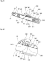
- the gasket pressing tool 3 of the present invention includes: a syringe attachment member 4 that is attached to the flange 23 of the outer tube 20; a gasket pressing member 8 having a tubular shape that can press the gasket 22 in the distal end direction; a pressing member biasing body 11 that has a distal end portion accommodated in the gasket pressing member 8 and has a rear end portion protruding from the gasket pressing member 8; a flange portion 60 that accommodates the rear end portion of the pressing member biasing body 11, and is accommodated in the syringe attachment member 4 in a distal end portion; a biasing body pressing tubular member 6 including opening portions 64 and 65 provided at side portions more on the rear side than the flange portion 60; and movement restriction members 7a and 7b having a distal end side held by the biasing body pressing tubular member 6 and/or the syringe attachment member 4, having engagement protrusions 72 that enter the inside of the biasing body pressing tubular member 6 through the opening portions 64 and 65, and
- the gasket pressing member 8 includes a plurality of pressing member-side engagement portions 83 that are arranged in the axial direction, and can engage with the engagement protrusions 72 of the movement restriction members 7a and 7b. Furthermore, the gasket pressing tool 3 has an engaged state maintaining function of maintaining the state of engagement between the engagement protrusions 72 of the movement restriction members 7a and 7b and the pressing member-side engagement portions 83 of the gasket pressing member 8 and an operation function for the engagement protrusions 72 for moving the engagement protrusions 72 to release the engagement between the engagement protrusions 72 and the pressing member-side engagement portions 83.
- the gasket pressing tool 3 of this embodiment has the operation function of releasing the engagement between the engagement protrusion 72 and the pressing member-side engagement portion 83 when an operation member 5 described later is pushed (i.e., longitudinal pushing).
- the movement restriction members 7a and 7b each include: a restriction member main body portion 71 that has a distal end portion held by the biasing body pressing tubular member 6, extends rearward from the distal end portion, and is elastically deformable; and the engagement protrusion 72 that extends in a direction toward the gasket pressing member 8 (that is, a direction from the inner surface toward the center of the gasket pressing tool 3) from the restriction member main body portion 71.
- a restriction member main body portion 71 that has a distal end portion held by the biasing body pressing tubular member 6, extends rearward from the distal end portion, and is elastically deformable
- the engagement protrusion 72 that extends in a direction toward the gasket pressing member 8 (that is, a direction from the inner surface toward the center of the
- the gasket pressing tool 3 of this embodiment includes the tubular operation member 5 attached to the rear end portion of the biasing body pressing tubular member 6 while being movable in an axial direction, to achieve an engagement protrusion operation function of the gasket pressing tool 3. As illustrated in Figs. 4 and 6 as well as Figs. 13 and 14 , the gasket pressing tool 3 of this embodiment includes the tubular operation member 5 attached to the rear end portion of the biasing body pressing tubular member 6 while being movable in an axial direction, to achieve an engagement protrusion operation function of the gasket pressing tool 3. As illustrated in Figs.
- the operation member 5 includes: engagement releasing protrusion portions 52 and 53 that come into contact with the restriction member main body portions 71 of the movement restriction members 7a and 7b when moving toward the distal end side, to push the restriction member main body portions 71 outward so that the engagement between the engagement protrusions 72 and the pressing member-side engagement portions 83 is released; and an operation member biasing body 12 that is accommodated in the operation member 5, and has a distal end that comes into contact with a rear end surface of the biasing body pressing tubular member 6 to bias the operation member 5 rearward.
- the gasket pressing tool 3 of this embodiment includes: the syringe attachment member 4; the tubular gasket pressing member 8; the pressing member biasing body 11 having a distal end side portion accommodated in the gasket pressing member 8; the biasing body pressing tubular member 6 that presses the pressing member biasing body 11 from the rear end side; the two movement restriction members 7a and 7b attached to the biasing body pressing tubular member 6; the operation member 5; and the operation member biasing body 12 that biases the operation member 5 rearward.
- the syringe attachment member 4 includes a main body portion 41 and an accommodation portion 42 formed by an arcuate recess portion extending downward from the upper surface of the main body portion 41.
- the accommodation portion 42 can accommodate the flange 23 of the outer tube 20 and the flange portion 60 of the biasing body pressing tubular member 6 at the same time. With these components thus accommodated, the gasket pressing tool 3 is attached (coupled) to the syringe 2 (outer tube 20).
- the syringe attachment member 4 can also be referred to as a syringe coupling member.
- the gasket pressing member 8 is a tubular body having a tubular main body portion 81 as illustrated in Figs. 4 , 6 to 9 , and 12 .
- the distal end portion is provided with a distal end inner surface portion with which the distal end of the pressing member biasing body 11 accommodated can be in contact (can engage).
- the outer surface of the distal end portion is provided with an attachment portion 82 for the gasket.
- the outer surface of the tubular main body portion 81 is provided with the plurality of the pressing member-side engagement portions 83 for engagement that are arranged at an equal interval along the axial direction of the gasket pressing member 8 (tubular main body portion 81).
- the pressing member-side engagement portions 83 are formed by a plurality of ribs formed on the outer surface of the gasket pressing member 8. It should be noted that the pressing member-side engagement portion 83 may have any configuration as long as it includes the front surface that can come into contact with (engage with) the rear surface of the engagement protrusion 72.
- the outer surface of the gasket pressing member 8 tubular main body portion 81
- a protrusion provided portion including the plurality of pressing member-side engagement portions 83 is provided. Further, in this embodiment, two protrusion provided portions, including the plurality of pressing member-side engagement portions 83, are formed facing each other.
- the gasket pressing member 8 has a distal end portion (specifically, the distal end surface of the tubular main body portion 81 or the gasket attachment portion 82) that can come into contact with the rear end portion of the gasket 22, and can press the gasket 22.
- the gasket pressing member 8 includes the plurality of pressing member-side engagement portions 83 adjacently arranged, as well as gaps into which the engagement protrusions 72 can enter from the outer surface side, the gaps each formed between the pressing member-side engagement portions 83 adjacent to each other in the axial direction.
- a compressible coil spring is used as the pressing member biasing body 11, as illustrated in Figs. 4 and 7 to 9 .
- the pressing member biasing body 11 may be a compressible tube-shaped elastic body.
- the pressing member biasing body 11 is longer in length than the inner cavity of the tubular main body portion 81 of the gasket pressing member 8, has the distal end side accommodated in the gasket pressing member 8, and has a rear end portion that protrudes from the rear end of the gasket pressing member 8 in a state illustrated in Figs. 4 and 7 to 9 , where the distal end surface is in contact with the distal end inner surface portion of the tubular main body portion 81.
- the biasing body pressing tubular member 6 is a member for pressing the pressing member biasing body 11 from the rear end side.
- the biasing body pressing tubular member 6 includes: a tubular main body portion 61; the flange portion 60 provided at the distal end portion of the main body portion 61; the opening portions 64 and 65 through which the engagement protrusions 72 of the movement restriction members 7a and 7b enter as described later, the opening portions 64 and 65 being provided at the side portions that are more on the rear side than the flange portion 60; attachment portions 62 and 63 for the movement restriction members 7a and 7b provided between the opening portions 64 and 65 and the flange portion 60; a bar shaped portion 67 that protrudes in the distal end direction from the rear end inner surface (bottom surface portion 66) and can enter the inside of the pressing member biasing body 11; and two axial direction recess portions 68 that are positioned more on the rear side than the
- the biasing body pressing tubular member 6 includes a guiding groove portion 69 including a circumferential groove portion extending in a circumferential direction from the rear end of each axial direction recess portion 68, and an axial direction groove portion extending in the axial direction from an end of the circumferential groove portion. Portions of the biasing body pressing tubular member 6 where the attachment portions 62 and 63 for the movement restriction members 7a and 7b are formed are bulging portions.
- the tubular main body portion 61 can accommodate the rear end portion of the pressing member biasing body 11.
- the bar shaped portion 67 enters into the pressing member biasing body 11, to restrict curving deformation of the pressing member biasing body 11 when the compressing (pressing) occurs in the pressing member biasing body 11.
- the movement restriction members 7a and 7b each include: the restriction member main body portion 71 that is elastically deformable; the engagement protrusion 72 that extends in the direction toward the gasket pressing member 8 from the main body portion 71 (that is, the direction from the inner surface toward the center of the gasket pressing tool 3); and the attachment portion 74 for the biasing body pressing tubular member 6 provided at the distal end portion 73.
- the movement restriction members 7a and 7b of this embodiment each have the restriction member main body portion 71 including a highly elastically deformable portion at a rear end portion of the distal end portion 73.
- the movement restriction members 7a and 7b can move up and down with the rear end of the distal end portions 73 of the restriction member main body portions 71 as the fulcrum.
- the two movement restriction members 7a and 7b are provided to face each other.
- the attachment portion 74 is formed by two leg portions 74a and 74b protruding from the lower surface of the distal end portion 73.
- the leg portions 74a and 74b each include: a distal end inclined surface; and a retaining portion formed at a rear end portion of the distal end inclined surface.
- the movement restriction members 7a and 7b are attached with the attachment portions 74 inserted in the attachment opening portions 64 and 65 of the biasing body pressing tubular member 6, specifically, with the two leg portions 74a and 74b inserted from the distal end inclined surface side and with the retaining portions provided through the attachment opening portions 64 and 65.
- the retaining portions of the attachment portions 74 engage with the inner surface of the biasing body pressing tubular member 6 near the attachment opening portions 64 and 65, whereby the movement restriction members 7a and 7b are less likely to be detached from the biasing body pressing tubular member 6, even when the restriction member main body portions 71 are pushed upward.
- the operation member 5 includes: the tubular main body portion 51; the engagement releasing protrusion portions 52 and 53 provided on the outer surface of the distal end portion of the main body portion 51; a window portion 54 extending in the axial direction; and sliding protrusions 56 and 57 provided on the inner surface of the distal end portion of the tubular main body portion 51 that is the inner side of the engagement releasing protrusion portions 52 and 53.
- the engagement releasing protrusion portions 52 and 53 of the operation member 5 include inclined surfaces inclined in the center axis direction and the distal end direction to be in contact with the lower surface of the restriction member main body portion 71.
- the sliding protrusions 56 and 57 enter the inside of the axial direction recess portion 68 of the biasing body pressing tubular member 6 to enable the operation member 5 slide in the axial direction of the biasing body pressing tubular member 6, and guides the engagement releasing protrusion portions 52 and 53 of the operation member 5 to the lower surfaces (inner surfaces) of the restriction member main body portions 71.
- the sliding protrusions 56 and 57 are inserted from the rear end of the axial direction groove portions of the guiding groove portions 69 of the biasing body pressing tubular member 6.
- the sliding protrusions 56 and 57 can enter the axial direction recess portions 68.
- the circumferential groove portion of the guiding groove portion 69 is provided with a retaining rib.
- the operation member biasing body 12 is accommodated in the operation member 5 (in the tubular main body portion 51).
- a compressible coil spring is preferably used as the operation member biasing body 12.
- the operation member biasing body 12 may be a compressible tubular elastic body. As illustrated in Figs. 4 and 13 , the operation member biasing body 12 has a distal end that comes into contact with the rear end outer surface of the biasing body pressing tubular member 6, has a rear end that comes into contact with the rear end inner surface of the operation member 5, and can be pressed (compressed) by these surfaces.
- the compressed operation member biasing body 12 presses (biases) the operation member 5 rearward.
- the two opening portions 64 and 65 of the biasing body pressing tubular member 6 are provided to face each other, the two engagement protrusions 72 of the movement restriction members 7a and 7b are provided to face each other, and the two engagement releasing protrusion portions 52 and 53 of the operation member 5 are provided to face each other, respectively.
- the pressing member biasing body 11 is compressed between the distal end inner surface of the gasket pressing member 8 and the rear end inner surface of the biasing body pressing tubular member 6, and thus is biasing the gasket pressing member 8 in the distal end direction.
- the movement restriction members 7a and 7b are attached to the biasing body pressing tubular member 6 so as to be pushed up outward.
- the engagement protrusions 72 that have been inserted through the opening portions 64 and 65 of the biasing body pressing tubular member 6 are pressed against the outer surface of the gasket pressing member 8, that is, in a state of pressing the outer surface of the gasket pressing member 8.
- the engagement protrusions 72 of the movement restriction members 7a and 7b are maintained in the state of being engaged with the pressing member-side engagement portions 83 of the gasket pressing member 8.
- the engagement protrusion 72 enters a gap between the two pressing member-side engagement portions 83, with the rear surface of the distal end portion of the engagement protrusion 72 being in contact with the front surface of any of the pressing member-side engagement portion 83.
- the engaged state is achieved.
- the tubular member 5 is biased rearward by the biasing member 12 relative to the biasing body pressing tubular member 6.
- the operation member 5 is moved furthest toward the rear side.
- the sliding protrusions 56 and 57 of the operation member 5 are in contact with the rear ends of the axial direction recess portions 68 of the biasing body pressing tubular member 6.
- the operation member 5 When the pressing of the operation member 5 stops, in the gasket pressing tool 3 of this embodiment, the operation member 5 is immediately pushed back toward the rear side by the biasing body 12, and thus retracts to the position illustrated in Fig. 4 .
- the engagement releasing protrusion portions 52 and 53 are also retracted, and thus the restriction member main body portion 71 is no longer pushed up outward.
- the engagement protrusion 72 is pushed down by the elastic deformation force to return to the original form, and thus is engaged again with the pressing member-side engagement portion 83.
- the gasket pressing member 8 and the gasket 22 also stop moving.
- the medicine can be administered only when the operation member 5 is pressed in the direction indicated by the arrow. Furthermore, the pressing member biasing body 11 assists the medicine administration.
- the medicine administration tool 100 of this embodiment includes: a syringe 2 including an outer tube 20 having a rear end portion provided with a flange 23 and a gasket 22 slidably accommodated in the outer tube 20; and the gasket pressing tool 103 of the present invention.
- a syringe 2 including an outer tube 20 having a rear end portion provided with a flange 23 and a gasket 22 slidably accommodated in the outer tube 20
- the gasket pressing tool 103 of the present invention As the syringe 2, a prefilled syringe 2a can be used.
- the medicine administration tool 100 may be in a state where the gasket pressing tool 103 is attached to the prefilled syringe 2a.
- the gasket pressing tool 103 of this embodiment has an operation function of releasing the engagement between engagement protrusions 172 and 173 and pressing member-side engagement portions 183, with operation pressing portions 176 and 177 of a movement restriction member 107 pushed toward the center side (i.e., lateral pressing), as described later.
- the movement restriction member 107 of the gasket pressing tool 103 of this embodiment includes an operation unit including: a ring-shaped distal end portion 171 held by a biasing body pressing tubular member 106 and/or a syringe attachment member 104; the engagement protrusions 172 and 173 that are positioned more on the rear side than the distal end portion 171 and provided in one end portion; the operation pressing portions 176 and 177; frames 174 and 175 that couple the engagement protrusions 172 and 173 and the operation pressing portions 176 and 177 to each other.
- the gasket pressing tool 103 includes pressing portion biasing bodies 115 and 116 that are disposed between each of the operation pressing portions 176 and 177 of the movement restriction member 107 and the biasing body pressing tubular member 106 and bias the operation pressing portions 176 and 177 outward. These components achieve the engaged state maintaining function.
- the engagement between the engagement protrusions 172 and 173 of the movement restriction member 107 and the pressing member-side engagement portions 183 of the gasket pressing member 108 is released, with the engagement protrusions 172 and 173 moved in the outward direction together with the frames 174 and 175 in response to the pressing of the operation pressing portions 176 and 177.
- the syringe attachment member 104 has two opening portions 165 and 166 of the biasing body pressing tubular member 106 facing each other, two operation units including the engagement protrusions, the operation pressing portion, and the frames facing each other, and two pressing portion biasing bodies 115 and 116 facing each other, respectively.
- the gasket pressing tool 103 of this embodiment includes: the syringe attachment member 104; the tubular gasket pressing member 108; a pressing member biasing body 111 having a distal end side portion accommodated in the gasket pressing member 108; the biasing body pressing tubular member 106 that presses the pressing member biasing body 111 from the rear end side; and the movement restriction member 107.
- the syringe attachment member 104 includes a main body portion 141 and an accommodation portion 142 formed by an arcuate recess portion extending downward from the upper surface of the main body portion 141.
- the accommodation portion 142 can accommodate the flange 23 of the outer tube 20 and a flange portion 162 of the biasing body pressing tubular member 106 at the same time. With these components thus accommodated, the gasket pressing tool 103 is attached (coupled) to the syringe 2 (outer tube 20).
- the syringe attachment member 104 can also be referred to as a syringe coupling member.
- the gasket pressing member 108 is a tubular body having a tubular main body portion 181 as illustrated in Figs. 21 and 24 to 26 .
- the distal end portion is provided with a distal end inner surface portion with which the distal end of the pressing member biasing body 111 accommodated can be in contact.
- the outer surface of the distal end portion is provided with an attachment portion 182 for the gasket.
- the outer surface of the tubular main body portion 181 is provided with the plurality of pressing member-side engagement portions 183 for engagement that are arranged at an equal interval along the axial direction of the gasket pressing member 108 (tubular main body portion 181).
- the gasket pressing member 108 includes a protrusion provided portion including the plurality of pressing member-side engagement portions 183. Furthermore, in this embodiment, two protrusion provided portions, including the plurality of pressing member-side engagement portions 183, are formed facing each other.
- the gasket pressing member 108 has a distal end portion (specifically, the distal end surface of the tubular main body portion 181 or the gasket attachment portion 182) that can come into contact with the rear end portion of the gasket 22, and thus can press the gasket 22.
- the gasket pressing member 108 includes the plurality of pressing member-side engagement portions 183 adjacently arranged, as well as gaps into which the engagement protrusions 172 and 173 can enter from the outer surface side, the gaps each formed between the pressing member-side engagement portions 183 adjacent to each other in the axial direction.
- the pressing member-side engagement portions 183 are formed by a plurality of ribs formed on the outer surface of the gasket pressing member 108. It should be noted that the pressing member-side engagement portion 183 may have any configuration as long as it has the front surface that can come into contact with (engage with) the rear surface of the engagement protrusion 172.
- the outer surface of the gasket pressing member 108 (tubular main body portion 181) may be provided with a plurality of groove portions having front surfaces that can come in contact with (engage with) the rear surfaces of the engagement protrusions 172.
- a compressible coil spring is used as the pressing member biasing body 111, as illustrated in Figs. 21 and 24 to 26 .
- the pressing member biasing body 111 may be a compressible tube-shaped elastic body.
- the pressing member biasing body 111 is longer in length than the inner cavity of the tubular main body portion 181 of the gasket pressing member 108, has the distal end side accommodated in the gasket pressing member 108, and has a rear end portion that protrudes from the rear end of the gasket pressing member 108 in a state illustrated in Figs. 21 and 24 to 26 , where the distal end surface is in contact with the distal end inner surface portion of the tubular main body portion 181.
- the biasing body pressing tubular member 106 is a member for pressing the pressing member biasing body 111 from the rear end side.
- a biasing body pressing tubular member 106 includes: a tubular main body portion 161; the flange portion 162 provided at the distal end portion of the main body portion 161; opening portions 165 and 166 through which the engagement protrusions 172 and 173 of the movement restriction member 107 enter, the opening portions 165 and 166 being provided at side portions that are more on the rear side than the flange portion 162; and a bar shaped portion 167 that protrudes in the distal end direction from the rear end inner surface (bottom surface portion 163) and can enter the inside of the pressing member biasing body 111.
- the tubular main body portion 161 can accommodate the rear end portion of the pressing member biasing body 111.
- the bar shaped portion 167 enters into the pressing member biasing body 111, to restrict curving deformation of the pressing member biasing body 111 when the compressing (pressing) occurs in the pressing member biasing body 111.
- the movement restriction member 107 includes a ring-shaped distal end portion 171 held between the outer surface of the biasing body pressing tubular member 106 and the inner surface of the syringe attachment member 104; the engagement protrusions 172 and 173 that are positioned more on the rear side than the distal end portion 171 and provided in one end portion; the operation pressing portions 176 and 177; frames 174 and 175 that couple the engagement protrusions 172 and 173 and the operation pressing portions 176 and 177 to each other; and coupling portions 178 and 179 that connect each of the operation pressing portions 176 and 177 and the ring-shaped distal end portion 171.
- the two coupling portions 178 and 179 of the movement restriction member 107 face each other and extend in a rear end direction from the rear end surface of the ring-shaped distal end portion 171.
- the operation pressing portions 176 and 177 are provided as bulging portions in the rear end portions of the coupling portions 178 and 179.
- the arc-shaped frames 174 and 175 extend from the operation pressing portions 176 and 177 and have distal end portions provided with protrusions that extend inward (direction toward the center of the movement restriction member 107). Distal end portions of the protrusions serve as engagement protrusions 172 and 173.
- the engagement protrusions 172 and 173 substantially face the respective operation pressing portions 176 and 177 coupled thereto by the frames 174 and 175.
- the movement restriction member 107 includes two independent operation units.
- the first operation unit includes the operation pressing portion 176, the engagement protrusion 172, the frame 174, and the coupling portion 178.
- the second operation unit includes the operation pressing portion 177, the engagement protrusion 173, the frame 175, and the coupling portion 179. Those components are connected to the ring-shaped distal end portion 171.
- the pressing portion biasing bodies 115 and 116 are each provided between the biasing body pressing tubular member 106 and a corresponding one of the operation pressing portions 176 and 177 of the movement restriction member 107.
- a compressible coil spring is used as the pressing member biasing bodies 115 and 116, as illustrated in Fig. 20 .
- the pressing member biasing bodies 115 and 116 may be a compressible tube-shaped elastic body.
- the operation pressing portions 176 and 177 are pressed outward by the pressing member biasing bodies 115 and 116.
- the engagement protrusions 172 and 173 coupled to the operation pressing portions 176 and 177 by the frames 174 and 175 are pressed inward, that is, against the outer surface of the gasket pressing member 108 as illustrated in Figs. 20 and 23 .
- the biasing body pressing tubular member 106 includes an accommodation portion that accommodates one end portions (lower end portions) of the pressing portion biasing bodies 115 and 116.
- the accommodation portion is formed by step portions (recess portions) provided at side portions of the opening portions 165 and 166.
- the engagement protrusions 172 and 173 provided through the opening portions 165 and 166 of the biasing body pressing tubular member 106 are pressed against the outer surface of the gasket pressing member 108, whereby the state where the gasket pressing member 108 and the pressing member-side engagement portion 183 are engaged is maintained.
- the state illustrated in Figs. 21 to 23 i.e., normal state which is the non-operated state illustrated in Fig. 16 and Fig.
- the engagement protrusions 172 and 173 each enter a gap between the two pressing member-side engagement portions 183, and the rear surface of the distal end portion of each of the engagement protrusions 172 and 173 comes into contact with the front surface of any of the pressing member-side engagement portions 183.
- the engagement protrusions 172 and 173 and the pressing member-side engagement portion 183 engaged with each other, the movement of the gasket pressing member 108 biased by the pressing member biasing body 111 in the distal end direction is restricted.
- the medicine can be administered only when the operation pressing portions 176 and 177 are pressed in the direction indicated by the arrow. Furthermore, the pressing member biasing body 111 assists the medicine administration.
- the medicine administration tool 200 of this embodiment includes: a syringe 2 including an outer tube 20 having a rear end portion provided with a flange 23 and a gasket 22 slidably accommodated in the outer tube 20; and the gasket pressing tool 203 of the present invention.
- a syringe 2 including an outer tube 20 having a rear end portion provided with a flange 23 and a gasket 22 slidably accommodated in the outer tube 20
- the gasket pressing tool 203 of the present invention As the syringe 2, a prefilled syringe 2a can be used.
- the medicine administration tool 200 may be in a state where the gasket pressing tool 203 is attached to the prefilled syringe 2a.
- the gasket pressing tool 203 of this embodiment has an operation function of releasing the engagement between an engagement protrusion 272 and the pressing member-side engagement portions 283, when the movement restriction member 207 is rotated as described later.
- the movement restriction member 207 of the gasket pressing tool 203 of this embodiment includes a tubular portion 271 that partially encloses the distal end portion of the biasing body pressing tubular member 206 and an engagement protrusion 272 provided on the inner surface of the tubular portion 271.
- the gasket pressing tool 203 includes an annular biasing body 212 that is disposed between the biasing body pressing tubular member 206 and the movement restriction member 207, has one end portion fixed to the biasing body pressing tubular member 206, has the other end portion fixed to the movement restriction member 207, and maintains the state where the engagement protrusion 272 and the pressing member-side engagement portion 283 of the gasket pressing member 208 are engaged. These components achieve the engaged state maintaining function.
- the gasket pressing tool 203 of this embodiment is configured in such a manner that when the movement restriction member 207 is rotated by a predetermined angle relative to the biasing body pressing tubular member 206, the engagement between the engagement protrusion 272 of the movement restriction member 207 and the pressing member-side engagement portion 283 of the gasket pressing member 208 is released, and that when the movement restriction member 207 is reversely rotated by the annular biasing body 212 in response to releasing of the rotation operation of the movement restriction member 207, the engagement protrusion 272 of the movement restriction member 207 and the pressing member-side engagement portion 283 of the gasket pressing member 208 engage with each other again.
- the gasket pressing tool 203 of this embodiment includes: a syringe attachment member 204; the tubular gasket pressing member 208; a pressing member biasing body 211 having a distal end side portion accommodated in the gasket pressing member 208; the biasing body pressing tubular member 206 that presses the pressing member biasing body 211 from the rear end side; and the movement restriction member 207.
- the syringe attachment member 204 includes a main body portion 241 and an accommodation portion 242 formed by an arcuate recess portion extending downward from the upper surface of the main body portion 241.
- the accommodation portion 242 can accommodate the flange 23 of the outer tube 20 and a flange portion 262 of the biasing body pressing tubular member 206 at the same time.
- the gasket pressing tool 203 is attached (coupled) to the syringe 2 (outer tube 20).
- the syringe attachment member 204 can also be referred to as a syringe coupling member.
- the gasket pressing member 208 is a tubular body having a tubular main body portion 281 as illustrated in Figs. 34 , 36 , and 39 to 41 .
- the distal end portion is provided with a distal end inner surface portion with which the distal end of the pressing member biasing body 211 accommodated can be in contact.
- the outer surface of the distal end portion is provided with an attachment portion 282 for the gasket.
- the outer surface of the tubular main body portion 281 is provided with a plurality of the pressing member-side engagement portions 283 that are arranged at an equal interval along the axial direction of the gasket pressing member 208 (tubular main body portion 281).
- the gasket pressing member 208 has a distal end portion (specifically, the distal end surface of the tubular main body portion 281 or the gasket attachment portion 282) that can come into contact with the rear end portion of the gasket 22, and can press the gasket 22.
- the gasket pressing member 208 (tubular main body portion 281) includes a plurality of groove portions formed on the outer surface, with the front surfaces of the groove portions forming the pressing member-side engagement portions 283 that can come into contact (can engage) with the rear surface of the engagement protrusion 272.
- the groove portions form gaps into which the engagement protrusion 272 can enter in the circumferential direction, between the pressing member-side engagement portions 283 adjacent to each other in the axial direction.
- the pressing member-side engagement portions 283 may be formed by protruding portions.
- a compressible coil spring is used as the pressing member biasing body 211, as illustrated in Figs. 34 , 39 , and 40 .
- the pressing member biasing body 211 may be a compressible tube-shaped elastic body.
- the pressing member biasing body 211 is longer in length than the inner cavity of the tubular main body portion 281 of the gasket pressing member 208, has the distal end side accommodated in the gasket pressing member 208, and has a rear end portion that protrudes from the rear end of the gasket pressing member 208 in a state illustrated in Figs. 34 , 39 , and 40 , where the distal end surface is in contact with the distal end inner surface portion of the tubular main body portion 281.
- the biasing body pressing tubular member 206 is a member for pressing the pressing member biasing body 211 from the rear end side.
- the biasing body pressing tubular member 206 includes: a tubular main body portion 261; a flange portion 262 provided at the distal end portion of the main body portion 261; an opening portion 263 through which the engagement protrusion 272 of the movement restriction member 207 described later enters, the opening portion 263 being provided at a side portion that is more on the rear side than the flange portion 262; and a bar shaped portion 265 that protrudes in the distal end direction from the rear end inner surface (bottom surface portion 264) and can enter the inside of the pressing member biasing body 211.
- the tubular main body portion 261 can accommodate the rear end portion of the pressing member biasing body 211.
- the bar shaped portion 265 enters into the pressing member biasing body 211, to restrict curving deformation of the pressing member biasing body 211 when the compressing (pressing) occurs in the pressing member biasing body 211.
- the movement restriction member 207 includes a tubular portion 271 that encloses the distal end portion of the biasing body pressing tubular member 206 and the engagement protrusion 272 provided on the inner surface of the tubular portion 271, as illustrated in Figs. 31 to 41 , in particular, in Figs. 36, 37 , and 39 to 41 . Then, the engagement protrusion 272 enters through the opening portion 263 of the biasing body pressing tubular member 206, with the distal end of the engagement protrusion 272 entering through a gap near the outer surface of the gasket pressing member 208, specifically, a gap between the pressing member-side engagement portions 283, which are adjacent to each other, of the gasket pressing member 208. The rear surface of the engagement protrusion 272 engages with the front surface of the pressing member-side engagement portion 283, whereby the movement of the gasket pressing member 208 in the distal end direction is restricted.
- the annular biasing body 212 This state where the movement of the gasket pressing member 208 in the distal end direction is restricted is maintained by the annular biasing body 212.
- a torsion spring or a torsion coil spring is used as the annular biasing body 212.
- the torsion coil spring is a spring that receives a torsion moment around the center axis of the coil.
- the torsion coil spring used as the annular biasing body 212 has one end portion fixed to the biasing body pressing tubular member 206, and has the other end portion fixed to the movement restriction member 207.
- the movement restriction member 207 is attached to the biasing body pressing tubular member 206 with the annular biasing body 212 interposed therebetween.
- the annular biasing body 212 causes the distal end of the engagement protrusion 272 to move into a gap between the pressing member-side engagement portions 283, which are adjacent to each other, of the gasket pressing member 208, whereby the state where the movement of the gasket pressing member 208 in the distal end direction is restricted is maintained.
- the movement restriction member 207 rotates about the center axis of the movement restriction member 207 (biasing body pressing tubular member 206).
- the engagement protrusion 272 of the movement restriction member 207 moves in the circumferential direction of the biasing body pressing tubular member 206, whereby the engagement between the engagement protrusion 272 and the pressing member-side engagement portion 283 is released.
- the pressing member-side engagement portion 283 appears in the engaged state, but does not extend to (not appear in) a direction of movement of the engagement protrusion 272 in the rotation of the movement restriction member 207.
- the biasing body 212 causes the gasket pressing member 208 to press the gasket 22 and move the gasket 22 in the distal end direction.
- the annular biasing body 212 immediately causes the movement restriction member 207 to reversely rotate.
- the engagement protrusion 272 again engages with the pressing member-side engagement portion 283, and the movement of the gasket pressing member 208 and the gasket 22 stops.
- the medicine can be administered only when the movement restriction member 207 is operated to rotate. Furthermore, the pressing member biasing body 211 assists the medicine administration.
- the medicine administration tool 300 of this embodiment includes: a syringe 2 including an outer tube 20 having a rear end portion provided with a flange 23 and a gasket 22 slidably accommodated in the outer tube 20; and the gasket pressing tool 303 of the present invention.
- a syringe 2 including an outer tube 20 having a rear end portion provided with a flange 23 and a gasket 22 slidably accommodated in the outer tube 20
- the gasket pressing tool 303 of the present invention As the syringe 2, a prefilled syringe 2a can be used.
- the medicine administration tool 300 may be in a state where the gasket pressing tool 303 is attached to the prefilled syringe 2a.
- the gasket pressing tool 303 of this embodiment has an operation function of releasing the engagement between an engagement protrusion 372 and a pressing member-side engagement portion 383, when the movement restriction member 307 is rotated with the operation member 305 being pressed (pushed) as described later.
- the movement restriction member 307 of the gasket pressing tool 303 of this embodiment includes a tubular portion 371 that partially encloses the biasing body pressing tubular member 306 and an engagement protrusion 372 provided on the inner surface of the tubular portion 371.
- the gasket pressing tool 303 further includes an annular biasing body 312 that is disposed between the biasing body pressing tubular member 306 and the movement restriction member, has one end portion fixed to the biasing body pressing tubular member 306, has the other end portion fixed to the movement restriction member 307, and maintains the state where the engagement protrusion 372 and the pressing member-side engagement portion 383 of the movement restriction member 307 are engaged.
- the gasket pressing tool 303 of this embodiment further includes a tubular operation member 305 that is attached to the rear end portion of the biasing body pressing tubular member 306, to be movable in the axial direction.
- the operation member 305 includes: a rotation protrusion portions 352 and 353 that come into contact with the movement restriction member 307 to rotate the movement restriction member 307 in a pushing operation toward the distal end side; and an operation member biasing body 313 that is accommodated in the operation member 305 and has a distal end coming into contact with the rear end surface of the biasing body pressing tubular member 306 to bias the operation member 305 rearward.
- the gasket pressing tool 303 of this embodiment is configured in such a manner that when the movement restriction member 307 rotates with the operation member 305 pushed, the engagement between the engagement protrusion 372 of the movement restriction member 307 and the pressing member-side engagement portion 383 of the gasket pressing member 308 is released.
- the operation member 305 is retracted, and the annular biasing body 312 causes the reverse rotation of the movement restriction member, whereby the engagement protrusion 372 of the movement restriction member and the pressing member-side engagement portion 383 of the gasket pressing member 308 are engaged with each other again.
- the gasket pressing tool 303 of this embodiment includes: a syringe attachment member 304; the tubular gasket pressing member 308; a pressing member biasing body 311 having a distal end side portion accommodated in the gasket pressing member 308; the biasing body pressing tubular member 306 that presses the pressing member biasing body 311 from the rear end side; the movement restriction member 307; the operation member 305; and an operation member biasing body 313 that biases the operation member 305 rearward.
- the syringe attachment member 304 includes a main body portion 341 and an accommodation portion 342 formed by an arcuate recess extending downward from the upper surface of the main body portion 341.
- the accommodation portion 342 can accommodate the flange 23 of the outer tube 20 and the flange portion 362 of the biasing body pressing tubular member 306 at the same time. With these components thus accommodated, the gasket pressing tool 303 is attached (coupled) to the syringe 2 (outer tube 20).
- the syringe attachment member 304 can also be referred to as a syringe coupling member.
- the gasket pressing member 308 is a tubular body having a tubular main body portion 381 as illustrated in Figs. 46 and 53 to 55 .
- the distal end portion is provided with a distal end inner surface portion with which the distal end of the pressing member biasing body 311 accommodated can be in contact.
- the outer surface of the distal end portion is provided with an attachment portion 382 for the gasket.
- the outer surface of the tubular main body portion 381 is provided with a plurality of the pressing member-side engagement portions 383 that are arranged at an equal interval along the axial direction of the gasket pressing member 308 (tubular main body portion 381).
- the gasket pressing member 308 (tubular main body portion 381) includes a plurality of groove portions formed on the outer surface, with the front surfaces of the groove portions forming the pressing member-side engagement portions 383 that can come into contact (can engage) with the rear surface of the engagement protrusion 372.
- the groove portions form gaps into which the engagement protrusion 372 can enter in the circumferential direction, between the engagement portions 383 adjacent to each other in the axial direction.
- the pressing member-side engagement portions 383 may be formed by protruding portions.
- the gasket pressing member 308 has a distal end portion (specifically, the distal end surface of the tubular main body portion 381 or the gasket attachment portion 382) that can engage with the rear end portion of the gasket 22, and can press the gasket 22.
- the gasket pressing member 308 includes the plurality of pressing member-side engagement portions 383 adjacently arranged, as well as gaps into which the engagement protrusions 372 can enter in the circumferential direction, the gaps each formed between the pressing member-side engagement portions 383 adjacent to each other in the axial direction.
- a compressible coil spring is used as the pressing member biasing body 311, as illustrated in Figs. 46 , 53 , and 54 .
- the pressing member biasing body 311 may be a compressible tube-shaped elastic body.
- the pressing member biasing body 311 is longer in length than the inner cavity of the tubular main body portion 381 of the gasket pressing member 308, has the distal end side accommodated in the gasket pressing member 308, and has a rear end portion that protrudes from the rear end of the gasket pressing member 308 in a state illustrated in Figs. 46 , 53 , and 54 , where the distal end surface is in contact with the distal end inner surface portion of the tubular main body portion 381.
- the biasing body pressing tubular member 306 is a member for pressing the pressing member biasing body 311 from the rear end side.
- the biasing body pressing tubular member 306 includes: a tubular main body portion 361; a flange portion 362 provided at the distal end portion of the main body portion 361; an opening portion 364 through which the engagement protrusion 372 of the movement restriction member 307 described later enters, the opening portion 364 being provided at a side portion that is more on the rear side than the flange portion 362; and a bar shaped portion 367 that protrudes in the distal end direction from the rear end inner surface (bottom surface portion 363) and can enter the inside of the pressing member biasing body 311.
- the tubular main body portion 361 can accommodate the rear end portion of the pressing member biasing body 311.
- the bar shaped portion 367 enters into the pressing member biasing body 311, to restrict curving deformation of the pressing member biasing body 311 when the compressing (pressing) occurs in the pressing member biasing body 311.
- the biasing body pressing tubular member 306 includes a guiding groove portion 369 including an axial direction recess portion 368, a circumferential groove portion extending in a circumferential direction from the rear end of the axial direction recess portion 368, and an axial direction groove portion extending in the axial direction from an end of the circumferential groove portion.
- the movement restriction member 307 includes a tubular portion 371 that encloses the distal end portion of the biasing body pressing tubular member 306 and an engagement protrusion 372 provided on the inner surface of the tubular portion 371, as illustrated in Figs. 42 to 55 , in particular, in Figs. 48, 49 , and 53 to 55 .
- the engagement protrusion 372 enters through the opening portion 364 of the biasing body pressing tubular member 306, with the distal end of the engagement protrusion 372 entering through a gap near the outer surface of the gasket pressing member 308, specifically, a gap between the pressing member-side engagement portions 383, which are adjacent to each other, of the gasket pressing member 308.
- the rear surface of the engagement protrusion 372 engages with the front surface of the pressing member-side engagement portion 383, whereby the movement of the gasket pressing member 308 in the distal end direction is restricted.
- the annular biasing body 312 Preferably, what is known as a torsion spring or a torsion coil spring is used as the annular biasing body 312.
- the torsion coil spring is a spring that receives a torsion moment around the center axis of the coil.
- the torsion coil spring used as the annular biasing body 312 has one end portion fixed to the biasing body pressing tubular member 306, and has the other end portion fixed to the movement restriction member 307.
- the movement restriction member 307 is fixed to the biasing body pressing tubular member 306 with the annular biasing body 312 interposed therebetween.
- the operation member 305 includes: a tubular main body portion 351; the rotation protrusion portions 352 and 353 provided on the outer surface of the distal end portion of the main body portion 351; and a sliding protrusion provided on the inner surface of the distal end portion of the tubular main body portion 351 that is the inner side of the rotation protrusion portions 352 and 353.
- the sliding protrusion enters into the axial direction recess portion 368 of the biasing body pressing tubular member 306 to enable the operation member 305 to be slidable in the axial direction of the biasing body pressing tubular member 6, and guides the rotation protrusion portions 352 and 353 of the operation member 305 to the outer surface of the tubular portion 371 of the movement restriction member 307.
- the sliding protrusion is inserted from the rear end of the axial direction groove portion of the guiding groove portion 369 of the biasing body pressing tubular member 306.
- the sliding protrusion can enter the axial direction recess portion 368.
- the circumferential groove portion of the guiding groove portion 369 is provided with a retaining rib.
- the movement restriction member 307 of the gasket pressing tool 303 of this embodiment includes an enclosed member-side inclined portion 374 that is provided on the outer surface of the movement restriction member 307 and is formed to be inclined in a rotation direction in which the engagement between the engagement protrusion 372 and the pressing member-side engagement portion 383 is released.
- the movement restriction member 307 includes an outer surface raised portion 373 the side wall of which forming the enclosed member-side inclined portion 374.
- the enclosed member-side inclined portion 374 may be formed by an inner side surface of a recess portion provided in the movement restriction member 307.
- the operation member 305 includes operation member side inclined portions 355 and 356 provided on the rotation protrusion portions 352 and 353, as illustrated in Figs. 46 , 48 , 51 , and 53 to 55 .
- the operation member side inclined portions 355 and 356 come into sliding contact with the enclosed member-side inclined portions 374 to rotate the movement restriction member 307.
- the operation member biasing body 313 is accommodated in the operation member 305 (in the tubular main body portion 351).
- a compressible coil spring is preferably used as the operation member biasing body 313.
- the pressing member biasing body 313 may be a compressible tube-shaped elastic body.
- the operation member biasing body 313 has a distal end that comes into contact with the rear end outer surface of the biasing body pressing tubular member 306, has a rear end that comes into contact with the rear end inner surface of the operation member 305, and can be pressed by these surfaces.
- the compressed operation member biasing body 313 presses (biases) the operation member 305 rearward.
- two enclosed member-side inclined portions 374 of the movement restriction member 307 are provided to face each other and two rotation protrusion portions 352 and 353 of the operation member 305 are provided to face each other, respectively.
- the annular biasing body 312 causes the distal end of the engagement protrusion 372 to move into a gap between the pressing member-side engagement portions 383, which are adjacent to each other, of the gasket pressing member 308, whereby the state where the movement of the gasket pressing member 308 in the distal end direction is restricted is maintained.
- the movement restriction member 307 rotates about the center axis of the movement restriction member 307 (the biasing body pressing tubular member 306).
- the engagement protrusion 372 of the movement restriction member 307 moves in the circumferential direction of the biasing body pressing tubular member 306, whereby the engagement between the engagement protrusion 372 and the pressing member-side engagement portion 383 is released.
- the pressing member-side engagement portion 383 appears in the engaged state, but does not extend to (not appear in) a movement direction of the engagement protrusion 372 when the movement restriction member 307 rotates.
- the biasing body 312 causes the gasket pressing member 308 to press the gasket 22 and move the gasket 22 in the distal end direction.
- the operation member 305 when pressing of the operation member 305 stops, the operation member 305 is moved by the biasing body 313, and the biasing body 312 immediately causes the reverse rotation of the movement restriction member 307.
- the engagement protrusion 372 again engages with the pressing member-side engagement portion 383, and the movement of the gasket pressing member 308 and the gasket 22 stops.
- the medicine can be administered only when the pushing operation is performed on the operation member 305. Furthermore, the pressing member biasing body 311 assists the medicine administration.
- the gasket pressing tool of the present invention is as follows.
Landscapes
- Health & Medical Sciences (AREA)
- Vascular Medicine (AREA)
- Engineering & Computer Science (AREA)
- Anesthesiology (AREA)
- Biomedical Technology (AREA)
- Heart & Thoracic Surgery (AREA)
- Hematology (AREA)
- Life Sciences & Earth Sciences (AREA)
- Animal Behavior & Ethology (AREA)
- General Health & Medical Sciences (AREA)
- Public Health (AREA)
- Veterinary Medicine (AREA)
- Infusion, Injection, And Reservoir Apparatuses (AREA)
Abstract
Description
- The present invention relates to a gasket pressing tool that biases a gasket of a syringe in a distal end direction to move the gasket in the distal end direction, and a medicine administration tool using the same.
- Conventionally, a prefilled syringe filled with liquid such as medicine in advance has been known. The prefilled syringe includes an outer tube accommodating medicine, a needle provided at a discharge port of the outer tube, a gasket slidable in the outer tube, and a plunger that presses the gasket in a distal end direction.
- The prefilled syringe may accommodate a viscous medicine with high injection resistance. Thus, not only self-administration but also an administration operation by a medical worker might not be easy.
- For example,
WO 2015/160600 (Patent Literature 1) discloses an injector that assists medication injection by utilizing spring force. - This injector includes: a connector having a distal end and a proximal end; a piston rod locked in said connector before medication injection; a spring configured to bias said piston rod distally; a releasable restraining means, where said piston rod moves distally under force of said spring upon release of said releasable restraining means; an activation means configured to release said releasable restraining means upon release of said releasable restraining means; and a mounting means for mounting a syringe at said distal end of said connector.
- Patent Literature 1:
WO 2015/160600 (US 2017-080159 A1 ) - Generally, when the prefilled syringe is used for medicine administration, the entire amount of medicine filled is administrated. However, depending on the patient's condition or the like, the medicine administered using the prefilled syringe might need to be interrupted, stopped, or administered in batches.
- However, with what is disclosed in
Patent Literature 1, an administration operation that has started continues until the medicine inside is completely discharged. The administration operation cannot be canceled halfway through. - An object of the present invention is to provide a gasket pressing tool and a medicine administration tool using the same with which a medicine discharge operation can be performed or assisted, the medicine discharge operation can be easily interrupted, and any desired amount of medicine can be administered.
- The above object is achieved with the following.
- A gasket pressing tool to move a gasket of a syringe including an outer tube and the gasket in a distal end direction, the outer tube having a rear end portion provided with a flange, the gasket being slidably accommodated in the outer tube, the gasket pressing tool including:
- a gasket pressing member capable of pressing the gasket in the distal end direction;
- a syringe attachment member attached to the flange of the outer tube;
- a pressing member biasing body having a distal end portion accommodated in the gasket pressing member and having a rear end portion protruding from the gasket pressing member;
- a biasing body pressing tubular member that accommodates the rear end portion of the pressing member biasing body and has a flange portion that is provided at a distal end portion and is accommodated in the syringe attachment member and an opening portion that is provided at a side portion more on a rear side than the flange portion; and
- a movement restriction member that is held by the biasing body pressing tubular member and/or the syringe attachment member, includes an engagement protrusion that enters into the biasing body pressing tubular member through the opening portion, and restricts a movement of the gasket pressing member, wherein
- the gasket pressing member includes a plurality of pressing member-side engagement portions arranged in an axial direction, the pressing member-side engagement portions being capable of engaging with the engagement protrusion of the movement restriction member, and
- the gasket pressing tool further has an engaged state maintaining function of maintaining a state of engagement between the engagement protrusion of the movement restriction member and the pressing member-side engagement portions of the gasket pressing member, and an engagement protrusion operation function of moving the engagement protrusion to release the engagement between the engagement protrusion and the pressing member-side engagement portion.
- The object described above is further achieved with the following.
- A medicine administration tool including: a syringe that includes an outer tube having a rear end portion provided with a flange and a gasket slidably accommodated in the outer tube; and the gasket pressing tool described above.
-
-
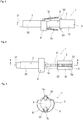
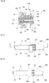
Fig. 1 is a front view of a medicine administration tool including a gasket pressing tool according to an embodiment of the present invention. -
Fig. 2 is a bottom view of the medicine administration tool illustrated inFig. 1 . -
Fig. 3 is a right side view of the medicine administration tool illustrated inFig. 1 . -
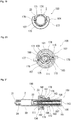
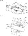
Fig. 4 is a cross-sectional view taken along line A-A illustrated inFig. 1 . -
Fig. 5 is a perspective view of the medicine administration tool illustrated inFig. 1 as seen obliquely from above. -
Fig. 6 is an enlarged view of the vicinity of a movement restriction member of the medicine administration tool illustrated inFig. 4 . -
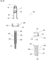
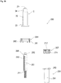
Fig. 7 is an explanatory diagram of components used in the medicine administration tool illustrated inFig. 1 . -
Fig. 8 is an explanatory diagram of components used in the medicine administration tool illustrated inFig. 1 . -
Fig. 9 is an explanatory diagram of components used in the medicine administration tool illustrated inFig. 1 . -
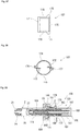
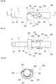
Fig. 10 is a front view of the movement restriction member used in the medicine administration tool illustrated inFig. 1 . -
Fig. 11 is a left side view of the movement restriction member illustrated inFig. 10 . -
Fig. 12 is an explanatory view of components of the gasket pressing tool used in the medicine administration tool illustrated inFig. 1 . -
Fig. 13 is an explanatory diagram for explaining an operation of the medicine administration tool illustrated inFig. 1 . -
Fig. 14 is an explanatory diagram for explaining an operation of the medicine administration tool illustrated inFig. 1 . -
Fig. 15 is a vertical cross-sectional view of an example of a prefilled syringe used for the medicine administration tool of the present invention. -
Fig. 16 is a front view of a medicine administration tool including a gasket pressing tool according to another embodiment of the present invention. -
Fig. 17 is a bottom view of the medicine administration tool illustrated inFig. 16 . -
Fig. 18 is a left side view of the medicine administration tool illustrated inFig. 16 . -
Fig. 19 is a right side view of the medicine administration tool illustrated inFig. 16 . -
Fig. 20 is a cross-sectional view taken along line C-C ofFig. 16 . -
Fig. 21 is a cross-sectional view taken along line B-B ofFig. 16 . -
Fig. 22 is a perspective view of the medicine administration tool illustrated inFig. 16 as seen obliquely from above. -
Fig. 23 is an enlarged view of the vicinity of a movement restriction member of the medicine administration tool illustrated inFig. 21 . -
Fig. 24 is an explanatory diagram of components used in the medicine administration tool illustrated inFig. 16 . -
Fig. 25 is an explanatory diagram of components used in the medicine administration tool illustrated inFig. 16 . -
Fig. 26 is an explanatory view of components of the gasket pressing tool used in the medicine administration tool illustrated inFig. 16 . -
Fig. 27 is a bottom view of the movement restriction member used in the medicine administration tool illustrated inFig. 16 . -
Fig. 28 is a right side view of the movement restriction member illustrated inFig. 27 . -
Fig. 29 is an explanatory diagram for explaining an operation of the medicine administration tool illustrated inFig. 16 . -
Fig. 30 is an explanatory diagram for explaining an operation of the medicine administration tool illustrated inFig. 16 . -
Fig. 31 is a front view of a medicine administration tool including a gasket pressing tool according to another embodiment of the present invention. -
Fig. 32 is a bottom view of the medicine administration tool illustrated inFig. 31 . -
Fig. 33 is a right side view of the medicine administration tool illustrated inFig. 31 . -
Fig. 34 is a cross-sectional view taken along line D-D ofFig. 31 . -
Fig. 35 is a perspective view of the medicine administration tool illustrated inFig. 31 as seen obliquely from above. -
Fig. 36 is an explanatory diagram for explaining an internal structure of the medicine administration tool illustrated inFig. 31 . -
Fig. 37 is an enlarged view of the vicinity of a movement restriction member of the medicine administration tool illustrated inFig. 36 . -
Fig. 38 is an explanatory diagram for explaining an operation of the medicine administration tool illustrated inFig. 31 . -
Fig. 39 is an explanatory diagram of components used in the medicine administration tool illustrated inFig. 31 . -
Fig. 40 is an explanatory diagram of components used in the medicine administration tool illustrated inFig. 31 . -
Fig. 41 is an explanatory view of components of the gasket pressing tool used in the medicine administration tool illustrated inFig. 31 . -
Fig. 42 is a front view of a medicine administration tool including a gasket pressing tool according to another embodiment of the present invention. -
Fig. 43 is a bottom view of the medicine administration tool illustrated inFig. 42 . -
Fig. 44 is a right side view of the medicine administration tool illustrated inFig. 42 . -
Fig. 45 is a left side view of the medicine administration tool illustrated inFig. 42 . -
Fig. 46 is a cross-sectional view taken along line E-E ofFig. 42 . -
Fig. 47 is a perspective view of the medicine administration tool illustrated inFig. 42 as seen obliquely from above. -
Fig. 48 is an explanatory diagram for explaining an internal structure of the medicine administration tool illustrated inFig. 42 . -
Fig. 49 is an enlarged view of the vicinity of a movement restriction member of the medicine administration tool illustrated inFig. 48 . -
Fig. 50 is an explanatory diagram for explaining an operation of the medicine administration tool illustrated inFig. 42 . -
Fig. 51 is an explanatory diagram for explaining an operation of the medicine administration tool illustrated inFig. 42 . -
Fig. 52 is an enlarged view of the vicinity of a movement restriction member of the medicine administration tool illustrated inFig. 51 . -
Fig. 53 is an explanatory diagram of components used in the medicine administration tool illustrated inFig. 42 . -
Fig. 54 is an explanatory diagram of components used in the medicine administration tool illustrated inFig. 42 . -
Fig. 55 is an explanatory view of components of the gasket pressing tool used in the medicine administration tool illustrated inFig. 42 . - A medicine administration tool and a gasket pressing tool of the present invention will be described with reference to embodiments illustrated in the drawings.
- A
medicine administration tool 1 of the present invention includes: asyringe 2 including anouter tube 20 having a rear end portion provided with aflange 23 and agasket 22 slidably accommodated in theouter tube 20; and a gasketpressing tool 3 of the present invention. As thesyringe 2, aprefilled syringe 2a can be used. Furthermore, themedicine administration tool 1 may be in a state where the gasketpressing tool 3 is attached to theprefilled syringe 2a. - The
prefilled syringe 2a as illustrated inFig. 15 may be used that includes theouter tube 20 having a tubular portion with a rear end portion provided with theflange 23, thegasket 22 slidably accommodated in theouter tube 20,medicine 26 filling theouter tube 20, and a distalend sealing member 25 of theouter tube 20. Theouter tube 20 illustrated includes anozzle portion 21 and acollar portion 24 that encloses thenozzle portion 21. - The gasket
pressing tool 3 of the present invention biases thegasket 22 of thesyringe 2 including theouter tube 20 having the rear end portion provided with theflange 23 and thegasket 22 slidably accommodated in theouter tube 20 in a distal end direction to move thegasket 22 in the distal end direction. - The gasket
pressing tool 3 of the present invention includes: asyringe attachment member 4 that is attached to theflange 23 of theouter tube 20; agasket pressing member 8 having a tubular shape that can press thegasket 22 in the distal end direction; a pressingmember biasing body 11 that has a distal end portion accommodated in thegasket pressing member 8 and has a rear end portion protruding from thegasket pressing member 8; aflange portion 60 that accommodates the rear end portion of the pressingmember biasing body 11, and is accommodated in thesyringe attachment member 4 in a distal end portion; a biasing body pressingtubular member 6 including openingportions flange portion 60; andmovement restriction members tubular member 6 and/or thesyringe attachment member 4, havingengagement protrusions 72 that enter the inside of the biasing body pressingtubular member 6 through the openingportions gasket pressing member 8. - The
gasket pressing member 8 includes a plurality of pressing member-side engagement portions 83 that are arranged in the axial direction, and can engage with theengagement protrusions 72 of themovement restriction members pressing tool 3 has an engaged state maintaining function of maintaining the state of engagement between theengagement protrusions 72 of themovement restriction members side engagement portions 83 of thegasket pressing member 8 and an operation function for theengagement protrusions 72 for moving theengagement protrusions 72 to release the engagement between theengagement protrusions 72 and the pressing member-side engagement portions 83. - First of all, the gasket
pressing tool 3 of the embodiment illustrated inFigs. 1 to 14 will be described. - As illustrated in
Fig. 1 to Fig. 6 , the gasketpressing tool 3 of this embodiment has the operation function of releasing the engagement between theengagement protrusion 72 and the pressing member-side engagement portion 83 when anoperation member 5 described later is pushed (i.e., longitudinal pushing). To enable this, themovement restriction members main body portion 71 that has a distal end portion held by the biasing body pressingtubular member 6, extends rearward from the distal end portion, and is elastically deformable; and theengagement protrusion 72 that extends in a direction toward the gasket pressing member 8 (that is, a direction from the inner surface toward the center of the gasket pressing tool 3) from the restriction membermain body portion 71. As illustrated inFigs. 4 and 6 , the state where theengagement protrusions 72 of themovement restriction members side engagement portions 83 of thegasket pressing member 8 is maintained in a non-operated state, with the restriction membermain body portion 71 pressing theengagement protrusion 72 in a direction toward the pressing member-side engagement portion 83 of thegasket pressing member 8. Thus, the engaged state maintaining function is achieved. - As illustrated in
Figs. 4 and 6 as well asFigs. 13 and14 , the gasketpressing tool 3 of this embodiment includes thetubular operation member 5 attached to the rear end portion of the biasing body pressingtubular member 6 while being movable in an axial direction, to achieve an engagement protrusion operation function of the gasketpressing tool 3. As illustrated inFigs. 13 and14 , theoperation member 5 includes: engagement releasingprotrusion portions main body portions 71 of themovement restriction members main body portions 71 outward so that the engagement between theengagement protrusions 72 and the pressing member-side engagement portions 83 is released; and an operationmember biasing body 12 that is accommodated in theoperation member 5, and has a distal end that comes into contact with a rear end surface of the biasing body pressingtubular member 6 to bias theoperation member 5 rearward. These components achieve the operation function for theengagement protrusions 72 of moving theengagement protrusions 72 and releasing the engagement between theengagement protrusions 72 and the pressing member-side engagement portions 83. - As illustrated in
Figs. 1 to 14 , and inFigs. 7 to 9 , and12 in particular, the gasketpressing tool 3 of this embodiment includes: thesyringe attachment member 4; the tubulargasket pressing member 8; the pressingmember biasing body 11 having a distal end side portion accommodated in thegasket pressing member 8; the biasing body pressingtubular member 6 that presses the pressingmember biasing body 11 from the rear end side; the twomovement restriction members tubular member 6; theoperation member 5; and the operationmember biasing body 12 that biases theoperation member 5 rearward. - As illustrated in
Figs. 1 ,4 to 9 , and12 , thesyringe attachment member 4 includes amain body portion 41 and anaccommodation portion 42 formed by an arcuate recess portion extending downward from the upper surface of themain body portion 41. Theaccommodation portion 42 can accommodate theflange 23 of theouter tube 20 and theflange portion 60 of the biasing body pressingtubular member 6 at the same time. With these components thus accommodated, the gasketpressing tool 3 is attached (coupled) to the syringe 2 (outer tube 20). Thesyringe attachment member 4 can also be referred to as a syringe coupling member. - The
gasket pressing member 8 is a tubular body having a tubularmain body portion 81 as illustrated inFigs. 4 ,6 to 9 , and12 . The distal end portion is provided with a distal end inner surface portion with which the distal end of the pressingmember biasing body 11 accommodated can be in contact (can engage). The outer surface of the distal end portion is provided with anattachment portion 82 for the gasket. Furthermore, the outer surface of the tubularmain body portion 81 is provided with the plurality of the pressing member-side engagement portions 83 for engagement that are arranged at an equal interval along the axial direction of the gasket pressing member 8 (tubular main body portion 81). - In this embodiment, the pressing member-
side engagement portions 83 are formed by a plurality of ribs formed on the outer surface of thegasket pressing member 8. It should be noted that the pressing member-side engagement portion 83 may have any configuration as long as it includes the front surface that can come into contact with (engage with) the rear surface of theengagement protrusion 72. For example, the outer surface of the gasket pressing member 8 (tubular main body portion 81) may be provided with a plurality of groove portions having front surfaces that can come into contact with (engage with) the rear surfaces of theengagement protrusions 72. - In this embodiment, a protrusion provided portion including the plurality of pressing member-
side engagement portions 83 is provided. Further, in this embodiment, two protrusion provided portions, including the plurality of pressing member-side engagement portions 83, are formed facing each other. Thegasket pressing member 8 has a distal end portion (specifically, the distal end surface of the tubularmain body portion 81 or the gasket attachment portion 82) that can come into contact with the rear end portion of thegasket 22, and can press thegasket 22. - Furthermore, the
gasket pressing member 8 includes the plurality of pressing member-side engagement portions 83 adjacently arranged, as well as gaps into which theengagement protrusions 72 can enter from the outer surface side, the gaps each formed between the pressing member-side engagement portions 83 adjacent to each other in the axial direction. - Preferably, a compressible coil spring is used as the pressing
member biasing body 11, as illustrated inFigs. 4 and7 to 9 . The pressingmember biasing body 11 may be a compressible tube-shaped elastic body. The pressingmember biasing body 11 is longer in length than the inner cavity of the tubularmain body portion 81 of thegasket pressing member 8, has the distal end side accommodated in thegasket pressing member 8, and has a rear end portion that protrudes from the rear end of thegasket pressing member 8 in a state illustrated inFigs. 4 and7 to 9 , where the distal end surface is in contact with the distal end inner surface portion of the tubularmain body portion 81. - As illustrated in
Fig. 4 , the biasing body pressingtubular member 6 is a member for pressing the pressingmember biasing body 11 from the rear end side. As illustrated inFigs. 4 ,7 to 9 , and12 , the biasing body pressingtubular member 6 includes: a tubularmain body portion 61; theflange portion 60 provided at the distal end portion of themain body portion 61; the openingportions engagement protrusions 72 of themovement restriction members portions flange portion 60;attachment portions movement restriction members portions flange portion 60; a bar shapedportion 67 that protrudes in the distal end direction from the rear end inner surface (bottom surface portion 66) and can enter the inside of the pressingmember biasing body 11; and two axialdirection recess portions 68 that are positioned more on the rear side than the openingportions - Furthermore, the biasing body pressing
tubular member 6 includes a guidinggroove portion 69 including a circumferential groove portion extending in a circumferential direction from the rear end of each axialdirection recess portion 68, and an axial direction groove portion extending in the axial direction from an end of the circumferential groove portion. Portions of the biasing body pressingtubular member 6 where theattachment portions movement restriction members main body portion 61 can accommodate the rear end portion of the pressingmember biasing body 11. The bar shapedportion 67 enters into the pressingmember biasing body 11, to restrict curving deformation of the pressingmember biasing body 11 when the compressing (pressing) occurs in the pressingmember biasing body 11. - As illustrated in
Figs. 4 to 14 , themovement restriction members main body portion 71 that is elastically deformable; theengagement protrusion 72 that extends in the direction toward thegasket pressing member 8 from the main body portion 71 (that is, the direction from the inner surface toward the center of the gasket pressing tool 3); and theattachment portion 74 for the biasing body pressingtubular member 6 provided at thedistal end portion 73. Themovement restriction members main body portion 71 including a highly elastically deformable portion at a rear end portion of thedistal end portion 73. Thus, themovement restriction members distal end portions 73 of the restriction membermain body portions 71 as the fulcrum. - In this embodiment, the two
movement restriction members Figs. 10 and 11 , theattachment portion 74 is formed by twoleg portions distal end portion 73. Theleg portions - The
movement restriction members attachment portions 74 inserted in theattachment opening portions tubular member 6, specifically, with the twoleg portions attachment opening portions attachment portions 74 engage with the inner surface of the biasing body pressingtubular member 6 near theattachment opening portions movement restriction members tubular member 6, even when the restriction membermain body portions 71 are pushed upward. - As illustrated in
Figs. 4, 5 , and7 to 13 , theoperation member 5 includes: the tubularmain body portion 51; the engagement releasingprotrusion portions main body portion 51; awindow portion 54 extending in the axial direction; and slidingprotrusions main body portion 51 that is the inner side of the engagement releasingprotrusion portions protrusion portions operation member 5 include inclined surfaces inclined in the center axis direction and the distal end direction to be in contact with the lower surface of the restriction membermain body portion 71. - The sliding
protrusions direction recess portion 68 of the biasing body pressingtubular member 6 to enable theoperation member 5 slide in the axial direction of the biasing body pressingtubular member 6, and guides the engagement releasingprotrusion portions operation member 5 to the lower surfaces (inner surfaces) of the restriction membermain body portions 71. The slidingprotrusions groove portions 69 of the biasing body pressingtubular member 6. When theoperation member 5 is rotated after the slidingprotrusions protrusions direction recess portions 68. Furthermore, the circumferential groove portion of the guidinggroove portion 69 is provided with a retaining rib. - As illustrated in
Figs. 4, 5 , and7 to 13 , the operationmember biasing body 12 is accommodated in the operation member 5 (in the tubular main body portion 51). A compressible coil spring is preferably used as the operationmember biasing body 12. The operationmember biasing body 12 may be a compressible tubular elastic body. As illustrated inFigs. 4 and13 , the operationmember biasing body 12 has a distal end that comes into contact with the rear end outer surface of the biasing body pressingtubular member 6, has a rear end that comes into contact with the rear end inner surface of theoperation member 5, and can be pressed (compressed) by these surfaces. The compressed operationmember biasing body 12 presses (biases) theoperation member 5 rearward. - In the gasket
pressing tool 3 of this embodiment, the two openingportions tubular member 6 are provided to face each other, the twoengagement protrusions 72 of themovement restriction members protrusion portions operation member 5 are provided to face each other, respectively. - When the gasket
pressing tool 3 of this embodiment is in a state illustrated inFig. 4 and 6 , the pressingmember biasing body 11 is compressed between the distal end inner surface of thegasket pressing member 8 and the rear end inner surface of the biasing body pressingtubular member 6, and thus is biasing thegasket pressing member 8 in the distal end direction. - In the gasket
pressing tool 3 of this embodiment, as illustrated inFigs. 4 and 6 , themovement restriction members tubular member 6 so as to be pushed up outward. The engagement protrusions 72 that have been inserted through the openingportions tubular member 6 are pressed against the outer surface of thegasket pressing member 8, that is, in a state of pressing the outer surface of thegasket pressing member 8. - Thus, in the gasket
pressing tool 3 of this embodiment, theengagement protrusions 72 of themovement restriction members side engagement portions 83 of thegasket pressing member 8. In the state illustrated inFigs. 4 to 6 (normal state, the state illustrated inFigs. 1 and 2 ), theengagement protrusion 72 enters a gap between the two pressing member-side engagement portions 83, with the rear surface of the distal end portion of theengagement protrusion 72 being in contact with the front surface of any of the pressing member-side engagement portion 83. Thus, the engaged state is achieved. With theengagement protrusion 72 and the pressing member-side engagement portion 83 thus engaged with each other, the movement of thegasket pressing member 8 biased by the pressingmember biasing body 11 in the distal end direction is restricted. - In the gasket
pressing tool 3 of this embodiment, as illustrated inFig. 4 , thetubular member 5 is biased rearward by the biasingmember 12 relative to the biasing body pressingtubular member 6. Thus, theoperation member 5 is moved furthest toward the rear side. Specifically, as illustrated inFig. 4 , the slidingprotrusions operation member 5 are in contact with the rear ends of the axialdirection recess portions 68 of the biasing body pressingtubular member 6. - As illustrated in
Fig. 13 , when theoperation member 5 is pushed in a direction indicated by the arrow, theoperation member 5 moves in the distal end direction. Then, as illustrated inFig. 14 , the engagement releasingprotrusion portions operation member 5 come into contact with the inner surfaces (lower surfaces) of the restriction membermain body portions 71 of the movement restriction member 7, to push up the restriction membermain body portions 71 in the direction indicated by an arrow (outward). The outward movement of the restriction membermain body portion 71 causes the outward movement of theengagement protrusion 72. As a result, theengagement protrusion 72 is no longer engaged with the pressing member-side engagement portion 83, and the engagement between these members is thus released. Thus, with the biasingbody 12, thegasket pressing member 8 presses thegasket 22 to move thegasket 22 in the distal end direction. - When the pressing of the
operation member 5 stops, in the gasketpressing tool 3 of this embodiment, theoperation member 5 is immediately pushed back toward the rear side by the biasingbody 12, and thus retracts to the position illustrated inFig. 4 . When theoperation member 5 is retracted, the engagement releasingprotrusion portions main body portion 71 is no longer pushed up outward. Theengagement protrusion 72 is pushed down by the elastic deformation force to return to the original form, and thus is engaged again with the pressing member-side engagement portion 83. Thus, thegasket pressing member 8 and thegasket 22 also stop moving. - Thus, with the gasket
pressing tool 3 of this embodiment, the medicine can be administered only when theoperation member 5 is pressed in the direction indicated by the arrow. Furthermore, the pressingmember biasing body 11 assists the medicine administration. - Next, a
medicine administration tool 100 and a gasketpressing tool 103 of an embodiment illustrated inFigs. 16 to 30 will be described. - The
medicine administration tool 100 of this embodiment includes: asyringe 2 including anouter tube 20 having a rear end portion provided with aflange 23 and agasket 22 slidably accommodated in theouter tube 20; and the gasketpressing tool 103 of the present invention. As thesyringe 2, aprefilled syringe 2a can be used. Furthermore, themedicine administration tool 100 may be in a state where the gasketpressing tool 103 is attached to theprefilled syringe 2a. - As illustrated in
Fig. 16 to Fig. 30 , the gasketpressing tool 103 of this embodiment has an operation function of releasing the engagement betweenengagement protrusions side engagement portions 183, withoperation pressing portions movement restriction member 107 pushed toward the center side (i.e., lateral pressing), as described later. - As illustrated in
Figs. 20 to 23 , themovement restriction member 107 of the gasketpressing tool 103 of this embodiment includes an operation unit including: a ring-shapeddistal end portion 171 held by a biasing body pressingtubular member 106 and/or asyringe attachment member 104; theengagement protrusions distal end portion 171 and provided in one end portion; theoperation pressing portions frames engagement protrusions operation pressing portions pressing tool 103 includes pressingportion biasing bodies operation pressing portions movement restriction member 107 and the biasing body pressingtubular member 106 and bias theoperation pressing portions - As illustrated in
Figs. 20 to 23 , in the gasketpressing tool 103 of this embodiment, the engagement between theengagement protrusions movement restriction member 107 and the pressing member-side engagement portions 183 of thegasket pressing member 108 is released, with theengagement protrusions frames operation pressing portions - When the pressing of the
operation pressing portions portion biasing bodies operation pressing portions engagement protrusions frames engagement protrusions movement restriction member 107 again engage with the pressing member-side engagement portions 183 of thegasket pressing member 108. - In the gasket
pressing tool 103 of this embodiment, as illustrated inFig. 20 , thesyringe attachment member 104 has two openingportions tubular member 106 facing each other, two operation units including the engagement protrusions, the operation pressing portion, and the frames facing each other, and two pressingportion biasing bodies - As illustrated in
Figs. 16 to 26 , and inFigs. 24 to 26 in particular, the gasketpressing tool 103 of this embodiment includes: thesyringe attachment member 104; the tubulargasket pressing member 108; a pressingmember biasing body 111 having a distal end side portion accommodated in thegasket pressing member 108; the biasing body pressingtubular member 106 that presses the pressingmember biasing body 111 from the rear end side; and themovement restriction member 107. - As illustrated in
Figs. 16 to 26 , thesyringe attachment member 104 includes amain body portion 141 and anaccommodation portion 142 formed by an arcuate recess portion extending downward from the upper surface of themain body portion 141. Theaccommodation portion 142 can accommodate theflange 23 of theouter tube 20 and aflange portion 162 of the biasing body pressingtubular member 106 at the same time. With these components thus accommodated, the gasketpressing tool 103 is attached (coupled) to the syringe 2 (outer tube 20). Thesyringe attachment member 104 can also be referred to as a syringe coupling member. - The
gasket pressing member 108 is a tubular body having a tubularmain body portion 181 as illustrated inFigs. 21 and24 to 26 . The distal end portion is provided with a distal end inner surface portion with which the distal end of the pressingmember biasing body 111 accommodated can be in contact. The outer surface of the distal end portion is provided with anattachment portion 182 for the gasket. The outer surface of the tubularmain body portion 181 is provided with the plurality of pressing member-side engagement portions 183 for engagement that are arranged at an equal interval along the axial direction of the gasket pressing member 108 (tubular main body portion 181). - In other words, the
gasket pressing member 108 includes a protrusion provided portion including the plurality of pressing member-side engagement portions 183. Furthermore, in this embodiment, two protrusion provided portions, including the plurality of pressing member-side engagement portions 183, are formed facing each other. Thegasket pressing member 108 has a distal end portion (specifically, the distal end surface of the tubularmain body portion 181 or the gasket attachment portion 182) that can come into contact with the rear end portion of thegasket 22, and thus can press thegasket 22. - Furthermore, the
gasket pressing member 108 includes the plurality of pressing member-side engagement portions 183 adjacently arranged, as well as gaps into which theengagement protrusions side engagement portions 183 adjacent to each other in the axial direction. - In this embodiment, the pressing member-
side engagement portions 183 are formed by a plurality of ribs formed on the outer surface of thegasket pressing member 108. It should be noted that the pressing member-side engagement portion 183 may have any configuration as long as it has the front surface that can come into contact with (engage with) the rear surface of theengagement protrusion 172. For example, the outer surface of the gasket pressing member 108 (tubular main body portion 181) may be provided with a plurality of groove portions having front surfaces that can come in contact with (engage with) the rear surfaces of theengagement protrusions 172. - Preferably, a compressible coil spring is used as the pressing
member biasing body 111, as illustrated inFigs. 21 and24 to 26 . The pressingmember biasing body 111 may be a compressible tube-shaped elastic body. The pressingmember biasing body 111 is longer in length than the inner cavity of the tubularmain body portion 181 of thegasket pressing member 108, has the distal end side accommodated in thegasket pressing member 108, and has a rear end portion that protrudes from the rear end of thegasket pressing member 108 in a state illustrated inFigs. 21 and24 to 26 , where the distal end surface is in contact with the distal end inner surface portion of the tubularmain body portion 181. - As illustrated in
Fig. 21 , the biasing body pressingtubular member 106 is a member for pressing the pressingmember biasing body 111 from the rear end side. As illustrated inFigs. 21 and24 to 26 , a biasing body pressingtubular member 106 includes: a tubularmain body portion 161; theflange portion 162 provided at the distal end portion of themain body portion 161; openingportions engagement protrusions movement restriction member 107 enter, the openingportions flange portion 162; and a bar shapedportion 167 that protrudes in the distal end direction from the rear end inner surface (bottom surface portion 163) and can enter the inside of the pressingmember biasing body 111. - The tubular
main body portion 161 can accommodate the rear end portion of the pressingmember biasing body 111. The bar shapedportion 167 enters into the pressingmember biasing body 111, to restrict curving deformation of the pressingmember biasing body 111 when the compressing (pressing) occurs in the pressingmember biasing body 111. - As illustrated in
Figs. 20 to 28 , inFigs. 20 and26 to 28 in particular, themovement restriction member 107 includes a ring-shapeddistal end portion 171 held between the outer surface of the biasing body pressingtubular member 106 and the inner surface of thesyringe attachment member 104; theengagement protrusions distal end portion 171 and provided in one end portion; theoperation pressing portions frames engagement protrusions operation pressing portions coupling portions operation pressing portions distal end portion 171. - The two
coupling portions movement restriction member 107 face each other and extend in a rear end direction from the rear end surface of the ring-shapeddistal end portion 171. Theoperation pressing portions coupling portions Figs. 26 and28 , the arc-shapedframes operation pressing portions engagement protrusions - As illustrated in
Figs. 20 and28 , theengagement protrusions operation pressing portions frames movement restriction member 107 includes two independent operation units. The first operation unit includes theoperation pressing portion 176, theengagement protrusion 172, theframe 174, and thecoupling portion 178. The second operation unit includes theoperation pressing portion 177, theengagement protrusion 173, theframe 175, and thecoupling portion 179. Those components are connected to the ring-shapeddistal end portion 171. - As illustrated in
Figs. 20, 21 , and23 , the pressingportion biasing bodies tubular member 106 and a corresponding one of theoperation pressing portions movement restriction member 107. Preferably, a compressible coil spring is used as the pressingmember biasing bodies Fig. 20 . The pressingmember biasing bodies operation pressing portions member biasing bodies engagement protrusions operation pressing portions frames gasket pressing member 108 as illustrated inFigs. 20 and23 . - In this embodiment, the biasing body pressing
tubular member 106 includes an accommodation portion that accommodates one end portions (lower end portions) of the pressingportion biasing bodies portions - In the gasket
pressing tool 103 of the present embodiment, as illustrated inFig. 20 , theengagement protrusions portions tubular member 106 are pressed against the outer surface of thegasket pressing member 108, whereby the state where thegasket pressing member 108 and the pressing member-side engagement portion 183 are engaged is maintained. In the state illustrated inFigs. 21 to 23 (i.e., normal state which is the non-operated state illustrated inFig. 16 and Fig. 17 ), theengagement protrusions side engagement portions 183, and the rear surface of the distal end portion of each of theengagement protrusions side engagement portions 183. With theengagement protrusions side engagement portion 183 engaged with each other, the movement of thegasket pressing member 108 biased by the pressingmember biasing body 111 in the distal end direction is restricted. - As illustrated in
Figs. 29 and30 , when the twooperation pressing portions movement restriction member 107 are simultaneously pressed in a direction indicated by an arrow, theengagement protrusions side engagement portions 183 is released. Thus, the engagement between these components is released. Thus, with the pressingmember biasing body 111, thegasket pressing member 108 presses thegasket 22 to move thegasket 22 in the distal end direction. - When the pressing of the
operation pressing portions pressing tool 103 of the present embodiment, theoperation pressing portions bodies engagement protrusions Figs. 29 and30 (inward). As a result, theengagement protrusions side engagement portions 183, whereby the movement of thegasket pressing member 108 and thegasket 22 also stops. - Thus, with the gasket
pressing tool 103 of this embodiment, the medicine can be administered only when theoperation pressing portions member biasing body 111 assists the medicine administration. - Next, a
medicine administration tool 200 and a gasketpressing tool 203 of an embodiment illustrated inFigs. 31 to 41 will be described. - The
medicine administration tool 200 of this embodiment includes: asyringe 2 including anouter tube 20 having a rear end portion provided with aflange 23 and agasket 22 slidably accommodated in theouter tube 20; and the gasketpressing tool 203 of the present invention. As thesyringe 2, aprefilled syringe 2a can be used. Furthermore, themedicine administration tool 200 may be in a state where the gasketpressing tool 203 is attached to theprefilled syringe 2a. - As illustrated in
Fig. 31 to Fig. 41 , the gasketpressing tool 203 of this embodiment has an operation function of releasing the engagement between anengagement protrusion 272 and the pressing member-side engagement portions 283, when themovement restriction member 207 is rotated as described later. - The
movement restriction member 207 of the gasketpressing tool 203 of this embodiment includes atubular portion 271 that partially encloses the distal end portion of the biasing body pressingtubular member 206 and anengagement protrusion 272 provided on the inner surface of thetubular portion 271. The gasketpressing tool 203 includes anannular biasing body 212 that is disposed between the biasing body pressingtubular member 206 and themovement restriction member 207, has one end portion fixed to the biasing body pressingtubular member 206, has the other end portion fixed to themovement restriction member 207, and maintains the state where theengagement protrusion 272 and the pressing member-side engagement portion 283 of thegasket pressing member 208 are engaged. These components achieve the engaged state maintaining function. - The gasket
pressing tool 203 of this embodiment is configured in such a manner that when themovement restriction member 207 is rotated by a predetermined angle relative to the biasing body pressingtubular member 206, the engagement between theengagement protrusion 272 of themovement restriction member 207 and the pressing member-side engagement portion 283 of thegasket pressing member 208 is released, and that when themovement restriction member 207 is reversely rotated by theannular biasing body 212 in response to releasing of the rotation operation of themovement restriction member 207, theengagement protrusion 272 of themovement restriction member 207 and the pressing member-side engagement portion 283 of thegasket pressing member 208 engage with each other again. - As illustrated in
Figs. 31 to 41 , and inFigs. 39 to 41 in particular, the gasketpressing tool 203 of this embodiment includes: asyringe attachment member 204; the tubulargasket pressing member 208; a pressingmember biasing body 211 having a distal end side portion accommodated in thegasket pressing member 208; the biasing body pressingtubular member 206 that presses the pressingmember biasing body 211 from the rear end side; and themovement restriction member 207. - As illustrated in
Figs. 31 to 41 , thesyringe attachment member 204 includes amain body portion 241 and anaccommodation portion 242 formed by an arcuate recess portion extending downward from the upper surface of themain body portion 241. Theaccommodation portion 242 can accommodate theflange 23 of theouter tube 20 and aflange portion 262 of the biasing body pressingtubular member 206 at the same time. With these components thus accommodated, the gasketpressing tool 203 is attached (coupled) to the syringe 2 (outer tube 20). Thesyringe attachment member 204 can also be referred to as a syringe coupling member. - The
gasket pressing member 208 is a tubular body having a tubularmain body portion 281 as illustrated inFigs. 34 ,36 , and39 to 41 . The distal end portion is provided with a distal end inner surface portion with which the distal end of the pressingmember biasing body 211 accommodated can be in contact. The outer surface of the distal end portion is provided with anattachment portion 282 for the gasket. The outer surface of the tubularmain body portion 281 is provided with a plurality of the pressing member-side engagement portions 283 that are arranged at an equal interval along the axial direction of the gasket pressing member 208 (tubular main body portion 281). - The
gasket pressing member 208 has a distal end portion (specifically, the distal end surface of the tubularmain body portion 281 or the gasket attachment portion 282) that can come into contact with the rear end portion of thegasket 22, and can press thegasket 22. - In this embodiment, the gasket pressing member 208 (tubular main body portion 281) includes a plurality of groove portions formed on the outer surface, with the front surfaces of the groove portions forming the pressing member-
side engagement portions 283 that can come into contact (can engage) with the rear surface of theengagement protrusion 272. The groove portions form gaps into which theengagement protrusion 272 can enter in the circumferential direction, between the pressing member-side engagement portions 283 adjacent to each other in the axial direction. The pressing member-side engagement portions 283 may be formed by protruding portions. - Preferably, a compressible coil spring is used as the pressing
member biasing body 211, as illustrated inFigs. 34 ,39 , and40 . The pressingmember biasing body 211 may be a compressible tube-shaped elastic body. The pressingmember biasing body 211 is longer in length than the inner cavity of the tubularmain body portion 281 of thegasket pressing member 208, has the distal end side accommodated in thegasket pressing member 208, and has a rear end portion that protrudes from the rear end of thegasket pressing member 208 in a state illustrated inFigs. 34 ,39 , and40 , where the distal end surface is in contact with the distal end inner surface portion of the tubularmain body portion 281. - As illustrated in
Fig. 34 , the biasing body pressingtubular member 206 is a member for pressing the pressingmember biasing body 211 from the rear end side. As illustrated inFigs. 34 ,39 , and40 , the biasing body pressingtubular member 206 includes: a tubularmain body portion 261; aflange portion 262 provided at the distal end portion of themain body portion 261; anopening portion 263 through which theengagement protrusion 272 of themovement restriction member 207 described later enters, theopening portion 263 being provided at a side portion that is more on the rear side than theflange portion 262; and a bar shapedportion 265 that protrudes in the distal end direction from the rear end inner surface (bottom surface portion 264) and can enter the inside of the pressingmember biasing body 211. - The tubular
main body portion 261 can accommodate the rear end portion of the pressingmember biasing body 211. The bar shapedportion 265 enters into the pressingmember biasing body 211, to restrict curving deformation of the pressingmember biasing body 211 when the compressing (pressing) occurs in the pressingmember biasing body 211. - The
movement restriction member 207 includes atubular portion 271 that encloses the distal end portion of the biasing body pressingtubular member 206 and theengagement protrusion 272 provided on the inner surface of thetubular portion 271, as illustrated inFigs. 31 to 41 , in particular, inFigs. 36, 37 , and39 to 41 . Then, theengagement protrusion 272 enters through theopening portion 263 of the biasing body pressingtubular member 206, with the distal end of theengagement protrusion 272 entering through a gap near the outer surface of thegasket pressing member 208, specifically, a gap between the pressing member-side engagement portions 283, which are adjacent to each other, of thegasket pressing member 208. The rear surface of theengagement protrusion 272 engages with the front surface of the pressing member-side engagement portion 283, whereby the movement of thegasket pressing member 208 in the distal end direction is restricted. - This state where the movement of the
gasket pressing member 208 in the distal end direction is restricted is maintained by theannular biasing body 212. Preferably, what is known as a torsion spring or a torsion coil spring is used as theannular biasing body 212. The torsion coil spring is a spring that receives a torsion moment around the center axis of the coil. - In the gasket
pressing tool 203 of this embodiment, the torsion coil spring used as theannular biasing body 212 has one end portion fixed to the biasing body pressingtubular member 206, and has the other end portion fixed to themovement restriction member 207. Thus, themovement restriction member 207 is attached to the biasing body pressingtubular member 206 with theannular biasing body 212 interposed therebetween. - In the gasket
pressing tool 203 of this embodiment, in the normal state which is a state where themovement restriction member 207 is not operated, as illustrated inFigs. 36 and 37 , theannular biasing body 212 causes the distal end of theengagement protrusion 272 to move into a gap between the pressing member-side engagement portions 283, which are adjacent to each other, of thegasket pressing member 208, whereby the state where the movement of thegasket pressing member 208 in the distal end direction is restricted is maintained. - Furthermore, in the gasket
pressing tool 203 of this embodiment, when the rotational force is applied to themovement restriction member 207 against the biasing force of theannular biasing body 212, themovement restriction member 207 rotates about the center axis of the movement restriction member 207 (biasing body pressing tubular member 206). When themovement restriction member 207 rotates, theengagement protrusion 272 of themovement restriction member 207 moves in the circumferential direction of the biasing body pressingtubular member 206, whereby the engagement between theengagement protrusion 272 and the pressing member-side engagement portion 283 is released. - Preferably, with the rotational operation of the
movement restriction member 207, detachment of theengagement protrusion 272 from the gap between the adjacent pressing member-side engagement portions 283 in the circumferential direction is guaranteed. To this end, the pressing member-side engagement portion 283 appears in the engaged state, but does not extend to (not appear in) a direction of movement of theengagement protrusion 272 in the rotation of themovement restriction member 207. - As illustrated in
Fig. 38 , when the engagement between theengagement protrusion 272 and the pressing member-side engagement portion 283 is released by the operation of rotating themovement restriction member 207, the biasingbody 212 causes thegasket pressing member 208 to press thegasket 22 and move thegasket 22 in the distal end direction. - In the gasket
pressing tool 203 of this embodiment, when the rotation of themovement restriction member 207 stops, theannular biasing body 212 immediately causes themovement restriction member 207 to reversely rotate. Thus, theengagement protrusion 272 again engages with the pressing member-side engagement portion 283, and the movement of thegasket pressing member 208 and thegasket 22 stops. - Thus, with the gasket
pressing tool 203 of this embodiment, the medicine can be administered only when themovement restriction member 207 is operated to rotate. Furthermore, the pressingmember biasing body 211 assists the medicine administration. - Next, a
medicine administration tool 300 and a gasketpressing tool 303 of an embodiment illustrated inFigs. 42 to 55 will be described. - The
medicine administration tool 300 of this embodiment includes: asyringe 2 including anouter tube 20 having a rear end portion provided with aflange 23 and agasket 22 slidably accommodated in theouter tube 20; and the gasketpressing tool 303 of the present invention. As thesyringe 2, aprefilled syringe 2a can be used. Furthermore, themedicine administration tool 300 may be in a state where the gasketpressing tool 303 is attached to theprefilled syringe 2a. - As illustrated in
Fig. 42 to Fig. 55 , the gasketpressing tool 303 of this embodiment has an operation function of releasing the engagement between anengagement protrusion 372 and a pressing member-side engagement portion 383, when themovement restriction member 307 is rotated with theoperation member 305 being pressed (pushed) as described later. - The
movement restriction member 307 of the gasketpressing tool 303 of this embodiment includes atubular portion 371 that partially encloses the biasing body pressingtubular member 306 and anengagement protrusion 372 provided on the inner surface of thetubular portion 371. The gasketpressing tool 303 further includes anannular biasing body 312 that is disposed between the biasing body pressingtubular member 306 and the movement restriction member, has one end portion fixed to the biasing body pressingtubular member 306, has the other end portion fixed to themovement restriction member 307, and maintains the state where theengagement protrusion 372 and the pressing member-side engagement portion 383 of themovement restriction member 307 are engaged. These components achieve the engaged state maintaining function. - The gasket
pressing tool 303 of this embodiment further includes atubular operation member 305 that is attached to the rear end portion of the biasing body pressingtubular member 306, to be movable in the axial direction. Theoperation member 305 includes: arotation protrusion portions movement restriction member 307 to rotate themovement restriction member 307 in a pushing operation toward the distal end side; and an operationmember biasing body 313 that is accommodated in theoperation member 305 and has a distal end coming into contact with the rear end surface of the biasing body pressingtubular member 306 to bias theoperation member 305 rearward. - The gasket
pressing tool 303 of this embodiment is configured in such a manner that when themovement restriction member 307 rotates with theoperation member 305 pushed, the engagement between theengagement protrusion 372 of themovement restriction member 307 and the pressing member-side engagement portion 383 of thegasket pressing member 308 is released. When the pushing of theoperation member 305 is released, theoperation member 305 is retracted, and theannular biasing body 312 causes the reverse rotation of the movement restriction member, whereby theengagement protrusion 372 of the movement restriction member and the pressing member-side engagement portion 383 of thegasket pressing member 308 are engaged with each other again. - As illustrated in
Figs. 42 to 55 , and inFigs. 53 to 55 in particular, the gasketpressing tool 303 of this embodiment includes: asyringe attachment member 304; the tubulargasket pressing member 308; a pressingmember biasing body 311 having a distal end side portion accommodated in thegasket pressing member 308; the biasing body pressingtubular member 306 that presses the pressingmember biasing body 311 from the rear end side; themovement restriction member 307; theoperation member 305; and an operationmember biasing body 313 that biases theoperation member 305 rearward. - As illustrated in
Figs. 42 to 55 , thesyringe attachment member 304 includes amain body portion 341 and anaccommodation portion 342 formed by an arcuate recess extending downward from the upper surface of themain body portion 341. Theaccommodation portion 342 can accommodate theflange 23 of theouter tube 20 and theflange portion 362 of the biasing body pressingtubular member 306 at the same time. With these components thus accommodated, the gasketpressing tool 303 is attached (coupled) to the syringe 2 (outer tube 20). Thesyringe attachment member 304 can also be referred to as a syringe coupling member. - The
gasket pressing member 308 is a tubular body having a tubularmain body portion 381 as illustrated inFigs. 46 and53 to 55 . The distal end portion is provided with a distal end inner surface portion with which the distal end of the pressingmember biasing body 311 accommodated can be in contact. The outer surface of the distal end portion is provided with anattachment portion 382 for the gasket. The outer surface of the tubularmain body portion 381 is provided with a plurality of the pressing member-side engagement portions 383 that are arranged at an equal interval along the axial direction of the gasket pressing member 308 (tubular main body portion 381). - In this embodiment, the gasket pressing member 308 (tubular main body portion 381) includes a plurality of groove portions formed on the outer surface, with the front surfaces of the groove portions forming the pressing member-
side engagement portions 383 that can come into contact (can engage) with the rear surface of theengagement protrusion 372. The groove portions form gaps into which theengagement protrusion 372 can enter in the circumferential direction, between theengagement portions 383 adjacent to each other in the axial direction. The pressing member-side engagement portions 383 may be formed by protruding portions. - The
gasket pressing member 308 has a distal end portion (specifically, the distal end surface of the tubularmain body portion 381 or the gasket attachment portion 382) that can engage with the rear end portion of thegasket 22, and can press thegasket 22. - Furthermore, the
gasket pressing member 308 includes the plurality of pressing member-side engagement portions 383 adjacently arranged, as well as gaps into which theengagement protrusions 372 can enter in the circumferential direction, the gaps each formed between the pressing member-side engagement portions 383 adjacent to each other in the axial direction. - Preferably, a compressible coil spring is used as the pressing
member biasing body 311, as illustrated inFigs. 46 ,53 , and54 . The pressingmember biasing body 311 may be a compressible tube-shaped elastic body. The pressingmember biasing body 311 is longer in length than the inner cavity of the tubularmain body portion 381 of thegasket pressing member 308, has the distal end side accommodated in thegasket pressing member 308, and has a rear end portion that protrudes from the rear end of thegasket pressing member 308 in a state illustrated inFigs. 46 ,53 , and54 , where the distal end surface is in contact with the distal end inner surface portion of the tubularmain body portion 381. - As illustrated in
Fig. 46 , the biasing body pressingtubular member 306 is a member for pressing the pressingmember biasing body 311 from the rear end side. As illustrated inFigs. 46 ,53 , and54 , the biasing body pressingtubular member 306 includes: a tubularmain body portion 361; aflange portion 362 provided at the distal end portion of themain body portion 361; anopening portion 364 through which theengagement protrusion 372 of themovement restriction member 307 described later enters, theopening portion 364 being provided at a side portion that is more on the rear side than theflange portion 362; and a bar shapedportion 367 that protrudes in the distal end direction from the rear end inner surface (bottom surface portion 363) and can enter the inside of the pressingmember biasing body 311. The tubularmain body portion 361 can accommodate the rear end portion of the pressingmember biasing body 311. The bar shapedportion 367 enters into the pressingmember biasing body 311, to restrict curving deformation of the pressingmember biasing body 311 when the compressing (pressing) occurs in the pressingmember biasing body 311. - Furthermore, as illustrated in
Figs. 53 and55 , the biasing body pressingtubular member 306 includes a guidinggroove portion 369 including an axialdirection recess portion 368, a circumferential groove portion extending in a circumferential direction from the rear end of the axialdirection recess portion 368, and an axial direction groove portion extending in the axial direction from an end of the circumferential groove portion. - The
movement restriction member 307 includes atubular portion 371 that encloses the distal end portion of the biasing body pressingtubular member 306 and anengagement protrusion 372 provided on the inner surface of thetubular portion 371, as illustrated inFigs. 42 to 55 , in particular, inFigs. 48, 49 , and53 to 55 . Theengagement protrusion 372 enters through theopening portion 364 of the biasing body pressingtubular member 306, with the distal end of theengagement protrusion 372 entering through a gap near the outer surface of thegasket pressing member 308, specifically, a gap between the pressing member-side engagement portions 383, which are adjacent to each other, of thegasket pressing member 308. The rear surface of theengagement protrusion 372 engages with the front surface of the pressing member-side engagement portion 383, whereby the movement of thegasket pressing member 308 in the distal end direction is restricted. - This state where the movement of the
gasket pressing member 308 in the distal end direction is restricted is maintained by theannular biasing body 312. Preferably, what is known as a torsion spring or a torsion coil spring is used as theannular biasing body 312. The torsion coil spring is a spring that receives a torsion moment around the center axis of the coil. - In the gasket
pressing tool 303 of this embodiment, the torsion coil spring used as theannular biasing body 312 has one end portion fixed to the biasing body pressingtubular member 306, and has the other end portion fixed to themovement restriction member 307. Thus, themovement restriction member 307 is fixed to the biasing body pressingtubular member 306 with theannular biasing body 312 interposed therebetween. - As illustrated in
Figs. 42 to 55 , and inFigs. 46 ,48 ,51 , and53 to 55 , in particular, theoperation member 305 includes: a tubularmain body portion 351; therotation protrusion portions main body portion 351; and a sliding protrusion provided on the inner surface of the distal end portion of the tubularmain body portion 351 that is the inner side of therotation protrusion portions - The sliding protrusion enters into the axial
direction recess portion 368 of the biasing body pressingtubular member 306 to enable theoperation member 305 to be slidable in the axial direction of the biasing body pressingtubular member 6, and guides therotation protrusion portions operation member 305 to the outer surface of thetubular portion 371 of themovement restriction member 307. The sliding protrusion is inserted from the rear end of the axial direction groove portion of the guidinggroove portion 369 of the biasing body pressingtubular member 306. When theoperation member 305 is rotated after the sliding protrusion reaches the circumferential groove portion, the sliding protrusion can enter the axialdirection recess portion 368. Furthermore, the circumferential groove portion of the guidinggroove portion 369 is provided with a retaining rib. - As illustrated in
Figs. 42 ,47 ,53 , and55 , themovement restriction member 307 of the gasketpressing tool 303 of this embodiment includes an enclosed member-sideinclined portion 374 that is provided on the outer surface of themovement restriction member 307 and is formed to be inclined in a rotation direction in which the engagement between theengagement protrusion 372 and the pressing member-side engagement portion 383 is released. In this embodiment, themovement restriction member 307 includes an outer surface raisedportion 373 the side wall of which forming the enclosed member-sideinclined portion 374. The enclosed member-sideinclined portion 374 may be formed by an inner side surface of a recess portion provided in themovement restriction member 307. - The
operation member 305 includes operation member side inclinedportions rotation protrusion portions Figs. 46 ,48 ,51 , and53 to 55 . When the pushing operation is performed on theoperation member 305, the operation member side inclinedportions portions 374 to rotate themovement restriction member 307. - As illustrated in
Figs. 46 ,48 , and53 and54 , the operationmember biasing body 313 is accommodated in the operation member 305 (in the tubular main body portion 351). A compressible coil spring is preferably used as the operationmember biasing body 313. The pressingmember biasing body 313 may be a compressible tube-shaped elastic body. As illustrated inFig. 46 , the operationmember biasing body 313 has a distal end that comes into contact with the rear end outer surface of the biasing body pressingtubular member 306, has a rear end that comes into contact with the rear end inner surface of theoperation member 305, and can be pressed by these surfaces. The compressed operationmember biasing body 313 presses (biases) theoperation member 305 rearward. - In the gasket
pressing tool 303 of this embodiment, two enclosed member-side inclinedportions 374 of themovement restriction member 307 are provided to face each other and tworotation protrusion portions operation member 305 are provided to face each other, respectively. - In the gasket
pressing tool 303 of this embodiment, in the normal state which is a state where theoperation member 305 is not operated (a state where themovement restriction member 307 is not rotated), as illustrated inFigs. 48 and 49 , theannular biasing body 312 causes the distal end of theengagement protrusion 372 to move into a gap between the pressing member-side engagement portions 383, which are adjacent to each other, of thegasket pressing member 308, whereby the state where the movement of thegasket pressing member 308 in the distal end direction is restricted is maintained. - In the gasket
pressing tool 303 of this embodiment, as illustrated inFig. 50 , when theoperation member 305 is pressed and pushed in, as illustrated inFigs. 50 and51 , theoperation member 305 moves forward and therotation protrusion portions operation member 305 come into sliding contact with the enclosed member-side inclinedportions 374 of themovement restriction member 307, whereby the rotational force against the biasing force of theannular biasing body 312 is applied to themovement restriction member 307. - As a result, as illustrated in
Figs. 51 and 52 , themovement restriction member 307 rotates about the center axis of the movement restriction member 307 (the biasing body pressing tubular member 306). When themovement restriction member 307 rotates, theengagement protrusion 372 of themovement restriction member 307 moves in the circumferential direction of the biasing body pressingtubular member 306, whereby the engagement between theengagement protrusion 372 and the pressing member-side engagement portion 383 is released. - Preferably, with the rotational operation of the
movement restriction member 307, detachment of theengagement protrusion 372 from the gap between the adjacent pressing member-side engagement portions 383 in the circumferential direction is guaranteed. To this end, the pressing member-side engagement portion 383 appears in the engaged state, but does not extend to (not appear in) a movement direction of theengagement protrusion 372 when themovement restriction member 307 rotates. - As illustrated in
Figs. 51 and 52 , when the engagement between theengagement protrusion 372 and the pressing member-side engagement portion 383 is released by the rotation operation of themovement restriction member 307, the biasingbody 312 causes thegasket pressing member 308 to press thegasket 22 and move thegasket 22 in the distal end direction. - In the gasket
pressing tool 303 of this embodiment, when pressing of theoperation member 305 stops, theoperation member 305 is moved by the biasingbody 313, and the biasingbody 312 immediately causes the reverse rotation of themovement restriction member 307. Thus, theengagement protrusion 372 again engages with the pressing member-side engagement portion 383, and the movement of thegasket pressing member 308 and thegasket 22 stops. - Thus, with the gasket
pressing tool 303 of this embodiment, the medicine can be administered only when the pushing operation is performed on theoperation member 305. Furthermore, the pressingmember biasing body 311 assists the medicine administration. - The gasket pressing tool of the present invention is as follows.
- (1) A gasket pressing tool to move a gasket of a syringe including an outer tube and the gasket in a distal end direction, the outer tube having a rear end portion provided with a flange, the gasket being slidably accommodated in the outer tube, the gasket pressing tool including:
- a gasket pressing member capable of pressing the gasket in the distal end direction;
- a syringe attachment member attached to the flange of the outer tube;
- a pressing member biasing body having a distal end portion accommodated in the gasket pressing member and having a rear end portion protruding from the gasket pressing member;
- a biasing body pressing tubular member that accommodates the rear end portion of the pressing member biasing body and has a flange portion that is provided at a distal end portion and is accommodated in the syringe attachment member and an opening portion that is provided at a side portion more on a rear side than the flange portion; and
- a movement restriction member that is held by the biasing body pressing tubular member and/or the syringe attachment member, includes an engagement protrusion that enters into the biasing body pressing tubular member through the opening portion, and restricts a movement of the gasket pressing member, wherein
- the gasket pressing member includes a plurality of pressing member-side engagement portions arranged in an axial direction, the pressing member-side engagement portions being capable of engaging with the engagement protrusion of the movement restriction member, and
- the gasket pressing tool further has an engaged state maintaining function of maintaining a state of engagement between the engagement protrusion of the movement restriction member and the pressing member-side engagement portions of the gasket pressing member, and an engagement protrusion operation function of moving the engagement protrusion to release the engagement between the engagement protrusion and the pressing member-side engagement portion.
The gasket pressing tool of the present invention moves the gasket of the syringe including the outer tube having the rear end portion provided with the flange and the gasket slidably accommodated in the outer tube in the distal end direction. The gasket pressing tool includes a gasket pressing member capable of pressing the gasket in the distal end direction, a syringe attachment member attached to the flange of the outer tube, a pressing member biasing body having a distal end portion accommodated in the gasket pressing member and having a rear end portion protruding from the gasket pressing member, a biasing body pressing tubular member that accommodates the rear end portion of the pressing member biasing body and has a flange portion that is provided at a distal end portion and is accommodated in the syringe attachment member and an opening portion that is provided at a side portion more on a rear side than the flange portion, and a movement restriction member that is held by the biasing body pressing tubular member and/or the syringe attachment member, includes an engagement protrusion that enters into the biasing body pressing tubular member through the opening portion, and restricts a movement of the gasket pressing member, and the gasket pressing member includes a plurality of pressing member-side engagement portions arranged in an axial direction, the pressing member-side engagement portions being capable of engaging with the engagement protrusion of the movement restriction member, and
the gasket pressing tool further has an engaged state maintaining function of maintaining a state of engagement between the engagement protrusion of the movement restriction member and the pressing member-side engagement portions of the gasket pressing member, and an engagement protrusion operation function of moving the engagement protrusion to release the engagement between the engagement protrusion and the pressing member-side engagement portion.
In the gasket pressing tool in a normal state, the engagement protrusion of the operation member is engaged with the pressing member-side engagement portions due to the engaged state maintaining function, and thus the forward movement of the gasket pressing member is restricted. When the engagement between the engagement protrusion of the operation member and the pressing member-side engagement portions is released due to the engagement protrusion operation function, the gasket pressing member is pressed in the distal end direction by the pressing member biasing body. Thus, with the gasket pressed by the biasing force of the pressing member biasing body, the movement of the gasket is favorably assisted and medicine can be easily discharged. When the engagement releasing by the engagement protrusion operation function ends, the engagement protrusion of the operation member and the pressing member-side engagement portions are engaged with each other again due to the engaged state maintaining function, whereby the forward movement of the gasket pressing member is restricted. Thus, the medicine discharge can be easily interrupted or stopped, and a predetermined amount of medicine can be easily discharged.
Further, the above embodiment may be as follows. - (2) The gasket pressing tool according to (1) described above, wherein the movement restriction member includes a restriction member main body portion that has a distal end portion held by the biasing body pressing tubular member, extends rearward from the distal end portion, and is elastically deformable, and the engagement protrusion extending in a direction toward the gasket pressing member from the main body portion, and the engaged state maintaining function is achieved with the restriction member main body portion pressing the engagement protrusion in a direction toward the pressing member-side engagement portions of the gasket pressing member.
- (3) The gasket pressing tool according to (1) or (2) described above, wherein the gasket pressing tool has the engagement protrusion operation function with the gasket pressing tool including a tubular operation member that is attached to a rear end portion of the biasing body pressing tubular member to be movable in the axial direction and an operation member biasing body that is accommodated in the operation member, has a distal end coming into contact with a rear end surface of the biasing body pressing tubular member, and biases the operation member rearward, and with the operation member including an engagement releasing protrusion portion that comes into contact with and pushes up the movement restriction member in moving toward a distal end side, to release the engagement between the engagement protrusion and the pressing member-side engagement portions.
- (4) The gasket pressing tool according to (1) described above, wherein the opening portion of the biasing body pressing tubular member and the engagement protrusion of the movement restriction member include two opening portions facing each other and two engagement protrusions facing each other, respectively.
- (5) The gasket pressing tool according to (3) described above, wherein the opening portion of the biasing body pressing tubular member, the engagement protrusion of the movement restriction member, and the engagement releasing protrusion portion of the operation member include two opening portions facing each other, two engagement protrusions facing each other, and two engagement releasing protrusion portions facing each other, respectively.
- (6) The gasket pressing tool according to (1) described above, wherein the gasket pressing tool has the engaged state maintaining function with the movement restriction member including an operation unit that includes a distal end portion held by the biasing body pressing tubular member and/or the syringe attachment member, the engagement protrusion that is provided more on the rear side than the distal end portion and is provided in one end portion, an operation pressing portion, and a frame coupling the engagement protrusion and the operation pressing portion to each other, and with the gasket pressing tool including a pressing portion biasing body that is disposed between the operation pressing portion of the movement restriction member and the biasing body pressing tubular member and biases the operation pressing portion outward.
- (7) The gasket pressing tool according to (6) described above, wherein the gasket pressing tool is configured in such a manner that when the operation pressing portion of the operation unit is pressed, the engagement protrusion moves in an outward direction together with the frame, to release the engagement between the engagement protrusion and the pressing member-side engagement portions of the movement restriction member, and that when the pressing of the operation pressing portion is released, the pressing portion biasing body pushes back the operation pressing portion to cause the engagement protrusion to move in an inward direction together with the frame, to make the engagement protrusion and the pressing member-side engagement portions engage with each other again.
- (8) The gasket pressing tool according to (6) or (7) described above, wherein the opening portion of the biasing body pressing tubular member, the operation unit, and the pressing portion biasing body include two opening portions facing each other, two operation units facing each other, and two pressing portion biasing bodies facing each other, respectively.
- (9) The gasket pressing tool according to any one of (6) to (8) described above, wherein the biasing body pressing tubular member includes an accommodation portion that accommodates one end portion of the pressing portion biasing body.
- (10) The gasket pressing tool according to any one of (1) to (9) described above, wherein the gasket pressing member includes a gap through which the engagement protrusion is able to enter from an outer surface side, the gap being provided between adjacent ones of the pressing member-side engagement portions in the axial direction.
- (11) The gasket pressing tool according (1) described above, wherein the gasket pressing member has the engaged state maintaining function with the movement restriction member including a tubular portion that partially encloses the biasing body pressing tubular member and has an inner surface provided with the engagement protrusion, and with the gasket pressing tool including an annular biasing body that is disposed between the biasing body pressing tubular member and the movement restriction member, has one end portion fixed to the biasing body pressing tubular member, has another end portion fixed to the movement restriction member, and maintains the state of engagement between the engagement protrusion and the pressing member-side engagement portions of the gasket pressing member.
- (12) The gasket pressing tool according to (11) described above, wherein the gasket pressing tool is configured in such a manner that when the movement restriction member is rotated by a predetermined angle relative to the biasing body pressing tubular member, the engagement between the engagement protrusion and the pressing member-side engagement portions is released, and that when an operation of rotating the movement restriction member is released, the engagement protrusion and the pressing member-side engagement portions are engaged with each other again with the annular biasing body causing reverse rotation of the movement restriction member.
- (13) The gasket pressing tool according to (11) or (12) described above, wherein the movement restriction member includes a gap through which the engagement protrusion is able to enter in a circumferential direction, the gap being provided between adjacent ones of the pressing member-side engagement portions.
- (14) The gasket pressing tool according to any one of (11) to (13) described above, wherein the engagement protrusion is detached in the circumferential direction from the gap between the adjacent ones of the pressing member-side engagement portions with a rotational operation of the movement restriction member.
- (15) The gasket pressing tool according (1) described above, wherein
the gasket pressing member has the engaged state maintaining function with the movement restriction member including a tubular portion that partially encloses the biasing body pressing tubular member and has an inner surface provided with the engagement protrusion, and with the gasket pressing tool including an annular biasing body that is disposed between the biasing body pressing tubular member and the movement restriction member, has one end portion fixed to the biasing body pressing tubular member, has another end portion fixed to the movement restriction member, and maintains the state of engagement between the engagement protrusion and the pressing member-side engagement portions of the gasket pressing member, and
the gasket pressing tool further includes a tubular operation member attached to a rear end portion of the biasing body pressing tubular member to be movable in the axial direction, and
the operation member includes rotation protrusion portion that comes into contact with the movement restriction member and rotates the movement restriction member in a pushing operation toward the distal end side, and an operation member biasing body that is accommodated in the operation member, has a distal end coming into contact with a rear end surface of the biasing body pressing tubular member, and biases the operation member rearward. - (16) The gasket pressing tool according to (15) described above, wherein the gasket pressing tool is configured in such a manner that, when the movement restriction member rotates with the operation member pushed, the engagement between the engagement protrusion of the movement restriction member and the pressing member-side engagement portions is released, and that when the movement restriction member is reversely rotated by the annular biasing body in response to releasing of the pushing of the operation member, the engagement protrusion of the movement restriction member and the pressing member-side engagement portions are engaged with each other again.
- (17) The gasket pressing tool according to (15) or (16) described above, wherein the movement restriction member includes an enclosed member-side inclined portion that is provided on an outer surface of the movement restriction member and is formed to be inclined in a rotation direction in which the engagement between the engagement protrusion and the pressing member-side engagement portions is released, and the rotation protrusion portion includes an operation member side inclined portion that, in the pushing operation, comes into sliding contact with the enclosed member-side inclined portion and rotates the movement restriction member.
- (18) The gasket pressing tool according to (17) described above, wherein the enclosed member-side inclined portion and the operation member side inclined portion include two enclosed member-side inclined portions facing each other and two operation member side inclined portions facing each other, respectively.
- (19) The gasket pressing tool according to any one of (15) to (18) described above, wherein the engagement protrusion is detached in a circumferential direction from the gap between the adjacent ones of the pressing member-side engagement portions, when the operation member is pushed and the movement restriction member is rotated.
- (20) The gasket pressing tool according to any one of (15) to (19) described above, wherein the gasket pressing member includes a gap through which the engagement protrusion is able to enter in the circumferential direction, the gap being provided between adjacent ones of the pressing member-side engagement portions.
- (21) The gasket pressing tool according to any one of (1) to (20) described above, wherein the biasing body pressing tubular member includes a bar shaped portion that protrudes in the distal end direction from a rear end inner surface and enters into the pressing member biasing body.
Furthermore, the medicine administration tool of the present invention is as follows. - (22) A medicine administration tool including: a syringe including an outer tube having a rear end portion provided with a flange and a gasket slidably accommodated in the outer tube; and the gasket pressing tool according to any one of (1) to (21) described above.
- (23) The medicine administration tool according to (22) described above, wherein the syringe is a prefilled syringe including medicine filling the outer tube and a distal end sealing member of the outer tube, and the medicine administration tool is in a state where the gasket pressing tool is attached to the prefilled syringe.
Claims (23)
- A gasket pressing tool to move a gasket of a syringe including an outer tube and the gasket in a distal end direction, the outer tube having a rear end portion provided with a flange, the gasket being slidably accommodated in the outer tube, the gasket pressing tool comprising:a gasket pressing member capable of pressing the gasket in the distal end direction;a syringe attachment member attached to the flange of the outer tube;a pressing member biasing body having a distal end portion accommodated in the gasket pressing member and having a rear end portion protruding from the gasket pressing member;a biasing body pressing tubular member that accommodates the rear end portion of the pressing member biasing body and has a flange portion that is provided at a distal end portion and is accommodated in the syringe attachment member and an opening portion that is provided at a side portion more on a rear side than the flange portion; anda movement restriction member that is held by the biasing body pressing tubular member and/or the syringe attachment member, includes an engagement protrusion that enters into the biasing body pressing tubular member through the opening portion, and restricts a movement of the gasket pressing member, whereinthe gasket pressing member includes a plurality of pressing member-side engagement portions arranged in an axial direction, the pressing member-side engagement portions being capable of engaging with the engagement protrusion of the movement restriction member, andthe gasket pressing tool further has an engaged state maintaining function of maintaining a state of engagement between the engagement protrusion of the movement restriction member and the pressing member-side engagement portions of the gasket pressing member, and an engagement protrusion operation function of moving the engagement protrusion to release the engagement between the engagement protrusion and the pressing member-side engagement portion.
- The gasket pressing tool according to claim 1, wherein the movement restriction member includes a restriction member main body portion that has a distal end portion held by the biasing body pressing tubular member, extends rearward from the distal end portion, and is elastically deformable, and the engagement protrusion extending in a direction toward the gasket pressing member from the main body portion, and the engaged state maintaining function is achieved with the restriction member main body portion pressing the engagement protrusion in a direction toward the pressing member-side engagement portions of the gasket pressing member.
- The gasket pressing tool according to claim 1 or 2, wherein the gasket pressing tool has the engagement protrusion operation function with the gasket pressing tool including a tubular operation member that is attached to a rear end portion of the biasing body pressing tubular member to be movable in the axial direction and an operation member biasing body that is accommodated in the operation member, has a distal end coming into contact with a rear end surface of the biasing body pressing tubular member, and biases the operation member rearward, and with the operation member including an engagement releasing protrusion portion that comes into contact with and pushes up the movement restriction member in moving toward a distal end side, to release the engagement between the engagement protrusion and the pressing member-side engagement portions.
- The gasket pressing tool according to claim 1, wherein the opening portion of the biasing body pressing tubular member and the engagement protrusion of the movement restriction member include two opening portions facing each other and two engagement protrusions facing each other, respectively.
- The gasket pressing tool according to claim 3, wherein the opening portion of the biasing body pressing tubular member, the engagement protrusion of the movement restriction member, and the engagement releasing protrusion portion of the operation member include two opening portions facing each other, two engagement protrusions facing each other, and two engagement releasing protrusion portions facing each other, respectively.
- The gasket pressing tool according to claim 1, wherein the gasket pressing tool has the engaged state maintaining function with the movement restriction member including an operation unit that includes a distal end portion held by the biasing body pressing tubular member and/or the syringe attachment member, the engagement protrusion that is provided more on the rear side than the distal end portion and is provided in one end portion, an operation pressing portion, and a frame coupling the engagement protrusion and the operation pressing portion to each other, and with the gasket pressing tool including a pressing portion biasing body that is disposed between the operation pressing portion of the movement restriction member and the biasing body pressing tubular member and biases the operation pressing portion outward.
- The gasket pressing tool according to claim 6, wherein the gasket pressing tool is configured in such a manner that when the operation pressing portion of the operation unit is pressed, the engagement protrusion moves in an outward direction together with the frame, to release the engagement between the engagement protrusion and the pressing member-side engagement portions of the movement restriction member, and that when the pressing of the operation pressing portion is released, the pressing portion biasing body pushes back the operation pressing portion to cause the engagement protrusion to move in an inward direction together with the frame, to make the engagement protrusion and the pressing member-side engagement portions engage with each other again.
- The gasket pressing tool according to claim 6 or 7, wherein the opening portion of the biasing body pressing tubular member, the operation unit, and the pressing portion biasing body include two opening portions facing each other, two operation units facing each other, and two pressing portion biasing bodies facing each other, respectively.
- The gasket pressing tool according to any one of claims 6 to 8, wherein the biasing body pressing tubular member includes an accommodation portion that accommodates one end portion of the pressing portion biasing body.
- The gasket pressing tool according to any one of claims 1 to 9, wherein the gasket pressing member includes a gap through which the engagement protrusion is able to enter from an outer surface side, the gap being provided between adjacent ones of the pressing member-side engagement portions in the axial direction.
- The gasket pressing tool according to claim 1, wherein the gasket pressing member has the engaged state maintaining function with the movement restriction member including a tubular portion that partially encloses the biasing body pressing tubular member and has an inner surface provided with the engagement protrusion, and with the gasket pressing tool including an annular biasing body that is disposed between the biasing body pressing tubular member and the movement restriction member, has one end portion fixed to the biasing body pressing tubular member, has another end portion fixed to the movement restriction member, and maintains the state of engagement between the engagement protrusion and the pressing member-side engagement portions of the gasket pressing member.
- The gasket pressing tool according to claim 11, wherein the gasket pressing tool is configured in such a manner that when the movement restriction member is rotated by a predetermined angle relative to the biasing body pressing tubular member, the engagement between the engagement protrusion and the pressing member-side engagement portions is released, and that when an operation of rotating the movement restriction member is released, the engagement protrusion and the pressing member-side engagement portions are engaged with each other again with the annular biasing body causing reverse rotation of the movement restriction member.
- The gasket pressing tool according to claim 11 or 12, wherein the movement restriction member includes a gap through which the engagement protrusion is able to enter in a circumferential direction, the gap being provided between adjacent ones of the pressing member-side engagement portions.
- The gasket pressing tool according to any one of claims 11 to 13, wherein the engagement protrusion is detached in the circumferential direction from the gap between the adjacent ones of the pressing member-side engagement portions, with a rotational operation of the movement restriction member.
- The gasket pressing tool according to claim 1, wherein
the gasket pressing member has the engaged state maintaining function with the movement restriction member including a tubular portion that partially encloses the biasing body pressing tubular member and has an inner surface provided with the engagement protrusion, and with the gasket pressing tool including an annular biasing body that is disposed between the biasing body pressing tubular member and the movement restriction member, has one end portion fixed to the biasing body pressing tubular member, has another end portion fixed to the movement restriction member, and maintains the state of engagement between the engagement protrusion and the pressing member-side engagement portions of the gasket pressing member, and
the gasket pressing tool further includes a tubular operation member attached to a rear end portion of the biasing body pressing tubular member to be movable in the axial direction, and the operation member includes rotation protrusion portion that comes into contact with the movement restriction member and rotates the movement restriction member in a pushing operation toward the distal end side, and an operation member biasing body that is accommodated in the operation member, has a distal end coming into contact with a rear end surface of the biasing body pressing tubular member, and biases the operation member rearward. - The gasket pressing tool according to claim 15, wherein the gasket pressing tool is configured in such a manner that, when the movement restriction member rotates with the operation member pushed, the engagement between the engagement protrusion of the movement restriction member and the pressing member-side engagement portions is released, and that when the movement restriction member is reversely rotated by the annular biasing body in response to releasing of the pushing of the operation member, the engagement protrusion of the movement restriction member and the pressing member-side engagement portions are engaged with each other again.
- The gasket pressing tool according to claim 15 or 16, wherein the movement restriction member includes an enclosed member-side inclined portion that is provided on an outer surface of the movement restriction member and is formed to be inclined in a rotation direction in which the engagement between the engagement protrusion and the pressing member-side engagement portions is released, and the rotation protrusion portion includes an operation member side inclined portion that, in the pushing operation, comes into sliding contact with the enclosed member-side inclined portion and rotates the movement restriction member.
- The gasket pressing tool according to claim 17, wherein the enclosed member-side inclined portion and the operation member side inclined portion include two enclosed member-side inclined portions facing each other and two operation member side inclined portions facing each other, respectively.
- The gasket pressing tool according to any one of claims 15 to 18, wherein the engagement protrusion is detached in a circumferential direction from the gap between the adjacent ones of the pressing member-side engagement portions, when the operation member is pushed and the movement restriction member is rotated.
- The gasket pressing tool according to any one of claims 15 to 19, wherein the gasket pressing member includes a gap through which the engagement protrusion is able to enter in the circumferential direction, the gap being provided between adjacent ones of the pressing member-side engagement portions.
- The gasket pressing tool according to any one of claims 1 to 20, wherein the biasing body pressing tubular member includes a bar shaped portion that protrudes in the distal end direction from a rear end inner surface and enters into the pressing member biasing body.
- A medicine administration tool comprising: a syringe including an outer tube having a rear end portion provided with a flange and a gasket slidably accommodated in the outer tube; and the gasket pressing tool according to any one of claims 1 to 21.
- The medicine administration tool according to claim 22, wherein the syringe is a prefilled syringe including medicine filling the outer tube and a distal end sealing member of the outer tube, and the medicine administration tool is in a state where the gasket pressing tool is attached to the prefilled syringe.
Applications Claiming Priority (2)
| Application Number | Priority Date | Filing Date | Title |
|---|---|---|---|
| JP2018063372 | 2018-03-28 | ||
| PCT/JP2019/012268 WO2019188853A1 (en) | 2018-03-28 | 2019-03-22 | Gasket pressing tool and liquid medicine administration tool using same |
Publications (3)
| Publication Number | Publication Date |
|---|---|
| EP3760259A1 true EP3760259A1 (en) | 2021-01-06 |
| EP3760259A4 EP3760259A4 (en) | 2021-04-28 |
| EP3760259B1 EP3760259B1 (en) | 2026-04-29 |
Family
ID=68061801
Family Applications (1)
| Application Number | Title | Priority Date | Filing Date |
|---|---|---|---|
| EP19775837.8A Active EP3760259B1 (en) | 2018-03-28 | 2019-03-22 | Gasket pressing tool and liquid medicine administration tool using same |
Country Status (4)
| Country | Link |
|---|---|
| US (1) | US12343508B2 (en) |
| EP (1) | EP3760259B1 (en) |
| JP (1) | JP7129471B2 (en) |
| WO (1) | WO2019188853A1 (en) |
Families Citing this family (1)
| Publication number | Priority date | Publication date | Assignee | Title |
|---|---|---|---|---|
| US11642466B2 (en) | 2019-05-03 | 2023-05-09 | Carefusion 303, Inc. | Syringe with priming mechanism |
Family Cites Families (9)
| Publication number | Priority date | Publication date | Assignee | Title |
|---|---|---|---|---|
| US2221739A (en) * | 1939-10-16 | 1940-11-12 | Reiter David | Hypodermic syringe |
| US7207971B2 (en) * | 2002-12-23 | 2007-04-24 | Boston Scientific Scimed, Inc. | Pressure relief devices for use with balloon catheters |
| US20050101919A1 (en) * | 2003-11-07 | 2005-05-12 | Lennart Brunnberg | Device for an injector |
| EP2085147B1 (en) * | 2008-01-29 | 2012-04-04 | Medmix Systems AG | Device with pressure charged piston for dispensing a multiple syringe or multiple cartridge |
| WO2010115670A1 (en) * | 2009-04-03 | 2010-10-14 | Shl Group Ab | Medicament delivery device |
| GB2488579A (en) * | 2011-03-02 | 2012-09-05 | Owen Mumford Ltd | Autoinjector with "injection complete" indicator |
| FR3007989B1 (en) * | 2013-07-05 | 2016-01-01 | Aptar France Sas | Autoinjector. |
| CN105579084A (en) | 2014-04-15 | 2016-05-11 | 魏民 | drug delivery device |
| FR3023170B1 (en) * | 2014-07-04 | 2016-08-19 | Aptar France Sas | Autoinjector. |
-
2019
- 2019-03-22 JP JP2020510000A patent/JP7129471B2/en active Active
- 2019-03-22 EP EP19775837.8A patent/EP3760259B1/en active Active
- 2019-03-22 WO PCT/JP2019/012268 patent/WO2019188853A1/en not_active Ceased
-
2020
- 2020-09-25 US US17/032,715 patent/US12343508B2/en active Active
Also Published As
| Publication number | Publication date |
|---|---|
| US20210008289A1 (en) | 2021-01-14 |
| JPWO2019188853A1 (en) | 2021-03-11 |
| EP3760259B1 (en) | 2026-04-29 |
| JP7129471B2 (en) | 2022-09-01 |
| EP3760259A4 (en) | 2021-04-28 |
| US12343508B2 (en) | 2025-07-01 |
| WO2019188853A1 (en) | 2019-10-03 |
Similar Documents
| Publication | Publication Date | Title |
|---|---|---|
| EP1755707B1 (en) | Injection device | |
| TWI541039B (en) | Auto-injector | |
| TWI537021B (en) | Auto-injector | |
| EP3856292B1 (en) | Safety syringe | |
| JP5721850B2 (en) | Drug delivery device | |
| CN106687162B (en) | Automatic injection device for multiple administration | |
| EP2934635B1 (en) | Prefillable auto-retractable safety syringe | |
| CN113056297B (en) | Medical injection system | |
| CN106492313A (en) | A kind of cassette full-automatic injecting pen | |
| AU2013362425A1 (en) | Prefillable auto-retractable safety syringe | |
| WO2017125733A1 (en) | Auto-injector apparatus | |
| EP3760259B1 (en) | Gasket pressing tool and liquid medicine administration tool using same | |
| CN206852873U (en) | A kind of cassette full-automatic injecting pen | |
| TW201739440A (en) | Container holder assembly for a medicament delivery device and medicament delivery device comprising the container holder assembly | |
| KR102808763B1 (en) | Syringe with multifunctional needle holder and retainer ring assembly | |
| CN106668989B (en) | Retractable syringe | |
| WO2023012335A1 (en) | Syringe- cartridge assembly | |
| KR20180096156A (en) | Disposable syringe auto disabie |
Legal Events
| Date | Code | Title | Description |
|---|---|---|---|
| STAA | Information on the status of an ep patent application or granted ep patent |
Free format text: STATUS: THE INTERNATIONAL PUBLICATION HAS BEEN MADE |
|
| PUAI | Public reference made under article 153(3) epc to a published international application that has entered the european phase |
Free format text: ORIGINAL CODE: 0009012 |
|
| STAA | Information on the status of an ep patent application or granted ep patent |
Free format text: STATUS: REQUEST FOR EXAMINATION WAS MADE |
|
| 17P | Request for examination filed |
Effective date: 20200930 |
|
| AK | Designated contracting states |
Kind code of ref document: A1 Designated state(s): AL AT BE BG CH CY CZ DE DK EE ES FI FR GB GR HR HU IE IS IT LI LT LU LV MC MK MT NL NO PL PT RO RS SE SI SK SM TR |
|
| AX | Request for extension of the european patent |
Extension state: BA ME |
|
| A4 | Supplementary search report drawn up and despatched |
Effective date: 20210325 |
|
| RIC1 | Information provided on ipc code assigned before grant |
Ipc: A61M 5/315 20060101AFI20210322BHEP Ipc: A61M 5/20 20060101ALI20210322BHEP Ipc: A61M 5/28 20060101ALI20210322BHEP Ipc: A61M 5/31 20060101ALN20210322BHEP |
|
| DAV | Request for validation of the european patent (deleted) | ||
| DAX | Request for extension of the european patent (deleted) | ||
| STAA | Information on the status of an ep patent application or granted ep patent |
Free format text: STATUS: EXAMINATION IS IN PROGRESS |
|
| 17Q | First examination report despatched |
Effective date: 20231004 |
|
| GRAP | Despatch of communication of intention to grant a patent |
Free format text: ORIGINAL CODE: EPIDOSNIGR1 |
|
| STAA | Information on the status of an ep patent application or granted ep patent |
Free format text: STATUS: GRANT OF PATENT IS INTENDED |
|
| RIC1 | Information provided on ipc code assigned before grant |
Ipc: A61M 5/315 20060101AFI20251218BHEP Ipc: A61M 5/20 20060101ALI20251218BHEP Ipc: A61M 5/28 20060101ALI20251218BHEP Ipc: A61M 5/31 20060101ALN20251218BHEP |
|
| INTG | Intention to grant announced |
Effective date: 20260105 |
|
| GRAS | Grant fee paid |
Free format text: ORIGINAL CODE: EPIDOSNIGR3 |
|
| GRAA | (expected) grant |
Free format text: ORIGINAL CODE: 0009210 |
|
| STAA | Information on the status of an ep patent application or granted ep patent |
Free format text: STATUS: THE PATENT HAS BEEN GRANTED |
|
| AK | Designated contracting states |
Kind code of ref document: B1 Designated state(s): AL AT BE BG CH CY CZ DE DK EE ES FI FR GB GR HR HU IE IS IT LI LT LU LV MC MK MT NL NO PL PT RO RS SE SI SK SM TR |
|
| REG | Reference to a national code |
Ref country code: CH Ref legal event code: F10 Free format text: ST27 STATUS EVENT CODE: U-0-0-F10-F00 (AS PROVIDED BY THE NATIONAL OFFICE) Effective date: 20260429 Ref country code: GB Ref legal event code: FG4D |