EP3760248A1 - Drug solution administration device and control method of drug solution administration device - Google Patents
Drug solution administration device and control method of drug solution administration device Download PDFInfo
- Publication number
- EP3760248A1 EP3760248A1 EP19775879.0A EP19775879A EP3760248A1 EP 3760248 A1 EP3760248 A1 EP 3760248A1 EP 19775879 A EP19775879 A EP 19775879A EP 3760248 A1 EP3760248 A1 EP 3760248A1
- Authority
- EP
- European Patent Office
- Prior art keywords
- liquid chemical
- pusher
- liquid
- administration device
- distal end
- Prior art date
- Legal status (The legal status is an assumption and is not a legal conclusion. Google has not performed a legal analysis and makes no representation as to the accuracy of the status listed.)
- Pending
Links
- 238000000034 method Methods 0.000 title claims abstract description 22
- 239000003814 drug Substances 0.000 title 2
- 229940079593 drug Drugs 0.000 title 2
- 239000007788 liquid Substances 0.000 claims abstract description 323
- 239000000126 substance Substances 0.000 claims abstract description 257
- 238000001514 detection method Methods 0.000 claims abstract description 103
- 230000004308 accommodation Effects 0.000 description 7
- 238000009434 installation Methods 0.000 description 5
- 230000000694 effects Effects 0.000 description 3
- 239000000463 material Substances 0.000 description 3
- 230000008602 contraction Effects 0.000 description 2
- 238000010586 diagram Methods 0.000 description 2
- 229920001971 elastomer Polymers 0.000 description 2
- 230000002093 peripheral effect Effects 0.000 description 2
- 230000001681 protective effect Effects 0.000 description 2
- 239000011347 resin Substances 0.000 description 2
- 229920005989 resin Polymers 0.000 description 2
- 238000007789 sealing Methods 0.000 description 2
- 210000001015 abdomen Anatomy 0.000 description 1
- 230000000052 comparative effect Effects 0.000 description 1
- 230000008878 coupling Effects 0.000 description 1
- 238000010168 coupling process Methods 0.000 description 1
- 238000005859 coupling reaction Methods 0.000 description 1
- 230000007423 decrease Effects 0.000 description 1
- 239000002934 diuretic Substances 0.000 description 1
- 230000001882 diuretic effect Effects 0.000 description 1
- 239000000806 elastomer Substances 0.000 description 1
- 238000003780 insertion Methods 0.000 description 1
- 230000037431 insertion Effects 0.000 description 1
- 239000002184 metal Substances 0.000 description 1
- 239000004084 narcotic analgesic agent Substances 0.000 description 1
- 102000004169 proteins and genes Human genes 0.000 description 1
- 108090000623 proteins and genes Proteins 0.000 description 1
- 210000000689 upper leg Anatomy 0.000 description 1
- 230000000007 visual effect Effects 0.000 description 1
Images


Classifications
-
- A—HUMAN NECESSITIES
- A61—MEDICAL OR VETERINARY SCIENCE; HYGIENE
- A61M—DEVICES FOR INTRODUCING MEDIA INTO, OR ONTO, THE BODY; DEVICES FOR TRANSDUCING BODY MEDIA OR FOR TAKING MEDIA FROM THE BODY; DEVICES FOR PRODUCING OR ENDING SLEEP OR STUPOR
- A61M5/00—Devices for bringing media into the body in a subcutaneous, intra-vascular or intramuscular way; Accessories therefor, e.g. filling or cleaning devices, arm-rests
- A61M5/14—Infusion devices, e.g. infusing by gravity; Blood infusion; Accessories therefor
- A61M5/142—Pressure infusion, e.g. using pumps
- A61M5/145—Pressure infusion, e.g. using pumps using pressurised reservoirs, e.g. pressurised by means of pistons
- A61M5/1452—Pressure infusion, e.g. using pumps using pressurised reservoirs, e.g. pressurised by means of pistons pressurised by means of pistons
-
- A—HUMAN NECESSITIES
- A61—MEDICAL OR VETERINARY SCIENCE; HYGIENE
- A61M—DEVICES FOR INTRODUCING MEDIA INTO, OR ONTO, THE BODY; DEVICES FOR TRANSDUCING BODY MEDIA OR FOR TAKING MEDIA FROM THE BODY; DEVICES FOR PRODUCING OR ENDING SLEEP OR STUPOR
- A61M5/00—Devices for bringing media into the body in a subcutaneous, intra-vascular or intramuscular way; Accessories therefor, e.g. filling or cleaning devices, arm-rests
- A61M5/14—Infusion devices, e.g. infusing by gravity; Blood infusion; Accessories therefor
- A61M5/142—Pressure infusion, e.g. using pumps
- A61M5/14244—Pressure infusion, e.g. using pumps adapted to be carried by the patient, e.g. portable on the body
- A61M5/14248—Pressure infusion, e.g. using pumps adapted to be carried by the patient, e.g. portable on the body of the skin patch type
-
- A—HUMAN NECESSITIES
- A61—MEDICAL OR VETERINARY SCIENCE; HYGIENE
- A61M—DEVICES FOR INTRODUCING MEDIA INTO, OR ONTO, THE BODY; DEVICES FOR TRANSDUCING BODY MEDIA OR FOR TAKING MEDIA FROM THE BODY; DEVICES FOR PRODUCING OR ENDING SLEEP OR STUPOR
- A61M5/00—Devices for bringing media into the body in a subcutaneous, intra-vascular or intramuscular way; Accessories therefor, e.g. filling or cleaning devices, arm-rests
- A61M5/14—Infusion devices, e.g. infusing by gravity; Blood infusion; Accessories therefor
- A61M5/168—Means for controlling media flow to the body or for metering media to the body, e.g. drip meters, counters ; Monitoring media flow to the body
-
- A—HUMAN NECESSITIES
- A61—MEDICAL OR VETERINARY SCIENCE; HYGIENE
- A61M—DEVICES FOR INTRODUCING MEDIA INTO, OR ONTO, THE BODY; DEVICES FOR TRANSDUCING BODY MEDIA OR FOR TAKING MEDIA FROM THE BODY; DEVICES FOR PRODUCING OR ENDING SLEEP OR STUPOR
- A61M2205/00—General characteristics of the apparatus
- A61M2205/58—Means for facilitating use, e.g. by people with impaired vision
- A61M2205/581—Means for facilitating use, e.g. by people with impaired vision by audible feedback
-
- A—HUMAN NECESSITIES
- A61—MEDICAL OR VETERINARY SCIENCE; HYGIENE
- A61M—DEVICES FOR INTRODUCING MEDIA INTO, OR ONTO, THE BODY; DEVICES FOR TRANSDUCING BODY MEDIA OR FOR TAKING MEDIA FROM THE BODY; DEVICES FOR PRODUCING OR ENDING SLEEP OR STUPOR
- A61M2205/00—General characteristics of the apparatus
- A61M2205/82—Internal energy supply devices
- A61M2205/8206—Internal energy supply devices battery-operated
-
- A—HUMAN NECESSITIES
- A61—MEDICAL OR VETERINARY SCIENCE; HYGIENE
- A61M—DEVICES FOR INTRODUCING MEDIA INTO, OR ONTO, THE BODY; DEVICES FOR TRANSDUCING BODY MEDIA OR FOR TAKING MEDIA FROM THE BODY; DEVICES FOR PRODUCING OR ENDING SLEEP OR STUPOR
- A61M5/00—Devices for bringing media into the body in a subcutaneous, intra-vascular or intramuscular way; Accessories therefor, e.g. filling or cleaning devices, arm-rests
- A61M5/178—Syringes
- A61M5/31—Details
- A61M5/315—Pistons; Piston-rods; Guiding, blocking or restricting the movement of the rod or piston; Appliances on the rod for facilitating dosing ; Dosing mechanisms
- A61M5/31565—Administration mechanisms, i.e. constructional features, modes of administering a dose
- A61M5/31566—Means improving security or handling thereof
- A61M5/3157—Means providing feedback signals when administration is completed
Definitions
- the present invention relates to a liquid chemical administration device and a control method for a liquid chemical administration device.
- a syringe pump liquid chemical administration device that administers a liquid chemical filled in a liquid chemical container into a living body by a pushing action of a pusher.
- This type of liquid chemical administration device includes a cylindrical liquid chemical container and a pusher mechanism that pushes out the liquid chemical in the liquid chemical container (see, for example, Patent Literature 1 below).
- the liquid chemical container and the pusher mechanism are accommodated in a housing and supported by the housing.
- Patent Literature 1 JP H9-294807 A
- completion of a liquid chemical filled in the liquid chemical container is performed, for example, by detecting, with a detection switch installed on an electric board or the like, that the pusher mechanism has moved forward by a predetermined distance.
- a control unit mounted on the liquid chemical administration device determines that the liquid chemical has run out, and stops a drive mechanism that moves the pusher forward. After that, the control unit notifies a user that the liquid supply is completed.
- the liquid chemical administration device if there is a deviation in installation accuracy of the detection switch, the pusher mechanism, the liquid chemical container, and the like, or dimensional accuracy of the pusher mechanism, the liquid chemical container, and the like, it becomes difficult to accurately detect a movement amount of the pusher mechanism by the detection switch. For example, if there is a deviation in the installation accuracy and the dimensional accuracy as described above, there is a possibility that the detection switch may detect "liquid supply completion (zero residual liquid)" even though the liquid chemical remains in the liquid chemical container. As a result, the liquid chemical administration device can no longer administer an amount of the liquid chemical that should be originally administered to the living body.
- the present invention has been made in view of the above problem, and an object of the present invention is to provide a liquid chemical administration device and a control method for a liquid chemical administration device that can prevent liquid supply of a liquid chemical from ending in a state where a liquid chemical remains in a liquid chemical container.
- the liquid chemical administration device of the present invention has: a liquid chemical container filled with a liquid chemical and having a distal end opening at a distal end; a housing that holds the liquid chemical container; a pusher that pushes out the liquid chemical in the liquid chemical container; a drive mechanism that advances the pusher toward the distal end opening of the liquid chemical container; a detection unit that detects a detection target part of the pusher and detects liquid supply completion of the liquid chemical based on a detection result; and a control unit that controls an operation of the drive mechanism. The control unit further advances the pusher after the detection unit detects the liquid supply completion.
- a control method for a liquid chemical administration device of the present invention is a control method for controlling movement of a pusher in a liquid chemical administration device including: a liquid chemical container filled with a liquid chemical and having a distal end opening at a distal end; a housing that holds the liquid chemical container; the pusher that pushes out the liquid chemical in the liquid chemical container; a drive mechanism that advances the pusher toward the distal end opening of the liquid chemical container; a detection unit that detects a detection target part of the pusher and detects liquid supply completion of the liquid chemical based on a detection result; and a control unit that controls an operation of the drive mechanism.
- the control unit further advances the pusher after the detection unit detects the liquid supply completion.
- liquid chemical administration device and the control method for the liquid chemical administration device of the present invention it is possible to prevent liquid supply of the liquid chemical from ending in a state where the liquid chemical remains in the liquid chemical container.
- Figs. 1 to 4 are views provided for explaining a liquid chemical administration system 10, a liquid chemical administration device 100, and an administration tool 200 according to the embodiment.
- Fig. 5 is a block diagram schematically showing a control system of a control unit 160
- Fig. 6 is a flowchart showing a control method for a liquid chemical administration device.
- Figs. 7 to 8 are views for explaining an action of the liquid chemical administration device 100 and a comparative example.
- Arrow X attached to each figure indicates a "longitudinal direction (a longitudinal direction of a liquid chemical container 110)" of the liquid chemical administration device 100
- arrow Y indicates a "width direction (a depth direction)” of the liquid chemical administration device 100
- arrow Z indicates a "height direction” of the liquid chemical administration device 100.
- the liquid chemical administration system 10 is used to administer a liquid chemical into a living body. As shown in Fig. 1 , the liquid chemical administration system 10 includes the liquid chemical administration device 100 and the administration tool 200.
- the liquid chemical administration device 100 and the administration tool 200 are configured as a patch type that is used by being attached to a body surface (skin) H of a user.
- a body part of the user to be attached with the liquid chemical administration device 100 and the administration tool 200 is not particularly limited, but is, for example, an abdomen or a thigh.
- the liquid chemical administration system 10 can continuously administer, for example, a liquid chemical (not shown) filled in the liquid chemical container 110 included in the liquid chemical administration device 100, into a living body over a relatively long time (for example, several minutes to several hours) through a pushing action of a pusher 130 described later. Note that the liquid chemical administration system 10 may intermittently administer the liquid chemical into the living body.
- the liquid chemical administration device 100 has the liquid chemical container 110 including a cylindrical (barrel-shaped) main body 111 filled with a liquid chemical, a housing 120 that holds the liquid chemical container 110, the pusher 130 that pushes out the liquid chemical in the liquid chemical container 110, a drive mechanism 140 that advances the pusher 130 toward a distal end opening of the liquid chemical container 110, a detection unit 150 that detects a detection target part 134 of the pusher 130 and detects liquid supply completion of the liquid chemical based on a detection result, and the control unit 160 that controls an operation of the drive mechanism.
- the liquid chemical container 110 including a cylindrical (barrel-shaped) main body 111 filled with a liquid chemical
- a housing 120 that holds the liquid chemical container 110
- the pusher 130 that pushes out the liquid chemical in the liquid chemical container 110
- a drive mechanism 140 that advances the pusher 130 toward a distal end opening of the liquid chemical container 110
- a detection unit 150 that detects a detection target part 134 of the pusher 130 and detects
- the housing 120 has a box-shaped housing main body 120a in which an accommodation space 128 is internally formed, and a chassis (corresponding to a "supporting part") 127 that is accommodated in the accommodation space 128 of the housing main body 120a and can be fixed to the housing main body 120a.
- a window 123a that enables visual recognition of an inside of the accommodation space 128 from an outside of the housing 120.
- the window 123a is formed by providing a transparent or semitransparent portion on a part of the housing main body 120a.
- a base end opening 125 for insertion of the chassis 127 into the accommodation space 128 of the housing main body 120a.
- the base end opening 125 of the housing main body 120a is closed by a lid member (not shown), with the chassis 127 accommodated in the accommodation space 128.
- a bottom surface 121 of the housing main body 120a is provided with a sheet-shaped sticking part (not shown) that can be stuck to the body surface H of the user.
- a releasable protective sheet is attached to a sticking surface of the sticking part.
- the chassis 127 holds the liquid chemical container 110, the pusher 130, the drive mechanism 140, the detection unit 150, the control unit 160, and a power supply unit 170.
- the liquid chemical container 110 is configured by a so-called pre-filled liquid chemical container. Therefore, the liquid chemical is filled in advance in an inner cavity 111a of the main body 111 of the liquid chemical container 110.
- the liquid chemical include a protein preparation, a narcotic analgesic, a diuretic, and the like.
- a sealing member (not shown) to prevent leaking of the liquid chemical is arranged at a distal end opening (a discharge port) formed at a distal end 112 of the liquid chemical container 110.
- the distal end opening of the liquid chemical container 110 is arranged so as to externally project from the housing main body 120a.
- a mounting part 115 which is to be connected to a tube 240 (see Fig. 1 ) described later, is attached to a distal end portion of the liquid chemical container 110 projecting from the housing main body 120a.
- a main body 131 of the pusher 130 is inserted into the inner cavity 111a of the main body 111 of the liquid chemical container 110 (see Figs. 4 and 7 ).
- a gasket 135 that is slidable with an inner wall of the liquid chemical container 110 is arranged.
- a base end side of the gasket 135 is liquid-tightly sealed, by an outer peripheral portion of the gasket 135 being in liquid-tight contact with an inner peripheral surface of the main body 111 of the liquid chemical container 110.
- the gasket 135 is configured to be able to contract in an advancement direction (the longitudinal direction) of the pusher 130, when the pusher 130 advances in a state where the gasket 135 abuts against a distal-end inner wall 112a (see Fig. 9 ) of the liquid chemical container 110.
- the gasket 135 can be made by a flexible resin material such as, for example, a rubber material or an elastomer so as to be able to contract as described above.
- the gasket 135 has a tapered shape in which an outer diameter decreases toward a distal end side. Further, the shape of the gasket 135 is formed to be substantially the same as a shape of the distal-end inner wall 112a of the liquid chemical container 110.
- the detection target part 134 is provided at a base end of the pusher 130.
- the detection target part 134 is used to detect liquid supply completion of the liquid chemical by the liquid chemical administration device 100. The method of detecting the liquid supply completion will be described later.
- the control unit 160 controls a liquid supply operation of the liquid chemical of the liquid chemical administration device 100.
- the control unit 160 can be configured by, for example, a known microcomputer (an electronic circuit element) mounted with a CPU, a RAM, a ROM, and the like.
- the control unit 160 centrally executes operation control of the drive mechanism 140, the detection unit 150, the power supply unit 170, and a notification unit 180 (see Fig. 5 ).
- the detection unit 150 is arranged on the chassis 127. As shown in Fig. 8 , when the detection target part 134 included in the pusher 130 comes into contact with the detection unit 150, the detection unit 150 detects liquid supply completion of the liquid chemical administration device 100.
- the detection unit 150 can be configured by, for example, a known contact sensor that emits a predetermined electric signal when the detection target part 134 comes into contact with the detection unit 150.
- the control unit 160 receives the electric signal from the detection target part 134, to acquire information regarding the liquid supply completion. Note that the detection unit 150 is not particularly limited in a specific configuration and the like as long as it is possible to detect a position of the detection target part 134 of the pusher 130 when the pusher 130 advances by a predetermined amount.
- the power supply unit 170 can be configured by, for example, a known battery or the like.
- the notification unit 180 notifies the user of liquid supply completion.
- the notification unit 180 can be configured by, for example, a speaker or the like that emits voice or sound indicating that the liquid supply is completed.
- the notification unit 180 can be accommodated in the accommodation space 128 of the housing main body 120a.
- the drive mechanism 140 has a motor 141 that receives a driving current from the power supply unit 170 to generate a rotational driving force, a reduction mechanism 143 including a gear or the like to transmit the rotational driving force of the motor 141, and a feed screw 147 connected to the reduction mechanism 143.
- the feed screw 147 is connected to a base-end connecting part 133 arranged near the base end of the pusher 130.
- the feed screw 147 converts a rotary motion transmitted from the reduction mechanism 143 into a linear motion, and advances the pusher 130 in the longitudinal direction (the X direction).
- the pusher 130 pushes out the liquid chemical from the inner cavity 111a of the main body 111 of the liquid chemical container 110 to the tube 240 (see Fig. 1 ), by advancing toward the distal end side of the liquid chemical container 110.
- Fig. 9 shows the liquid chemical container 110 and the pusher 130 in a state before administering the liquid chemical.
- the detection unit 150 is arranged so as to detect liquid supply completion before a distal end 135a of the pusher 130 abuts against the distal-end inner wall 112a of the liquid chemical container 110. More specifically, as shown in Fig. 9 , a first distance (d1) from the distal end 135a of the pusher 130 to the detection target part 134 is shorter than a second distance (d2) from the distal-end inner wall 112a of the liquid chemical container 110 to a position where the detection unit 150 is arranged.
- distal end 135a of the pusher 130 means the distal end of the gasket 135 when the gasket 135 is arranged on the pusher 130 as in the present embodiment.
- the control method for the liquid chemical administration device 100 has a step of advancing the pusher 130 in the liquid chemical container 110 (S101), a step of detecting liquid supply completion by the detection unit 150 detecting the detection target part 134 of the pusher 130 (S102), and a step of advancing the pusher 130 after liquid supply completion is detected by the detection unit 150 (S103).
- Fig. 7 shows a state before the pusher 130 advances in the liquid chemical container 110.
- the detection unit 150 detects the liquid supply completion.
- the pusher 130 is further advanced by a distance equal to or more than a distance until the distal end 135a of the pusher 130 abuts against the distal-end inner wall 112a of the liquid chemical container 110. This is for the following reason.
- the detection unit 150 detects liquid supply completion despite being in a state where the liquid chemical remains in the liquid chemical container 110 (a state where the distal end 135a of the pusher 130 is not in contact with the distal-end inner wall 112a of the liquid chemical container 110). If the liquid supply by the liquid chemical administration device 100 ends as it is, it becomes impossible to administer an amount of the liquid chemical that should be originally administered to the living body.
- the liquid chemical administration device 100 further advances the pusher 130 after the detection unit 150 detects the liquid supply completion. Therefore, the liquid chemical administration device 100 can preferably prevent occurrence of "remaining of the liquid chemical" due to a deviation or the like in installation accuracy or dimensional accuracy of each member. Particularly, in the present embodiment, it is possible to more reliably prevent the liquid chemical from remaining in the liquid chemical container 110 since the pusher 130 is advanced by a distance equal to or more than a distance until the distal end 135a of the pusher 130 abuts against the distal-end inner wall 112a of the liquid chemical container 110 after the liquid supply completion is detected.
- the detection unit 150 does not detect the liquid supply completion although the pusher 130 has advanced until the distal end 135a of the pusher 130 abuts against the distal-end inner wall 112a of the liquid chemical container 110.
- the gasket 135 included in the pusher 130 according to the present embodiment is configured to be able to contract in a state of abutting against the distal-end inner wall 112a of the liquid chemical container 110, in an advancement direction (the longitudinal direction) of the pusher 130 when the pusher 130 advances.
- the liquid chemical administration device 100 can further advance the pusher 130 by an amount of contraction of the gasket 135, even if the state shown in Fig. 11 is made to cause a situation where the advancement of the pusher 130 does not proceed. Therefore, in the liquid chemical administration device 100, the detection unit 150 can reliably detect the liquid supply completion.
- a timing for ending the advancement of the pusher 130 and a timing for notifying the liquid supply completion may be set at any timing, for example, after a predetermined time has elapsed after the detection unit 150 detects the liquid supply completion. Further, the advancement of the pusher 130 may be continued until the liquid chemical administration device 100 is removed from the living body, or may be continued as it is after the liquid supply is completed.
- the administration tool 200 is configured to be connectable to the liquid chemical administration device 100.
- the administration tool 200 has a connector 210, a needle tube 220 that is punctured into a living body, a puncture part (a cannula housing) 230, the tube 240, and a puncture assisting tool 250 that assists puncture of the needle tube 220 into the living body.
- the connector 210 is configured to be connectable to the liquid chemical administration device 100 via a mounting part 215 fixed to the connector 210.
- the mounting part 215 can be connected to the liquid chemical administration device 100 by being externally fitted to the mounting part 115 (see Fig. 4 ) provided near the distal end 112 of the liquid chemical container 110 projecting to an outside of the housing 120.
- a connecting needle part capable of puncturing a sealing member (not shown) arranged at the distal end portion of the liquid chemical container 110.
- the tube 240 communicates with the inner cavity 111a of the main body 111 of the liquid chemical container 110 via the connecting needle part.
- a flow path (not shown) that connects the tube 240 and an inner cavity of the needle tube 220 is formed inside the puncture part 230.
- a liquid chemical supplied to the puncture part 230 via the tube 240 is administered into the living body through the flow path formed inside the puncture part 230 and the needle tube 220.
- the puncture assisting tool 250 is attached to the puncture part 230 at a time of liquid supply of the liquid chemical to the user.
- the puncture assisting tool 250 holds an introduction needle (an inner needle) 251.
- the introduction needle 251 projects from a distal end of the needle tube 220, with the puncture assisting tool 250 attached to the puncture part 230.
- the puncture assisting tool 250 is removed from the puncture part 230 after the needle tube 220 is punctured into the living body.
- the introduction needle 251 is extracted from the inner cavity of the needle tube 220 when the puncture assisting tool 250 is removed from the puncture part 230.
- the puncture assisting tool 250 is removed, and the puncture part 230 is left on the body surface H of the user with the needle tube 220 placed in the living body.
- the pusher 130 of the liquid chemical administration device 100 advances in the liquid chemical container 110, the liquid chemical filled in the liquid chemical container 110 is supplied to the inner cavity of the needle tube 220 via the tube 240 and the flow path of the puncture part 230.
- the introduction needle 251 can be configured by, for example, a metal needle. Further, the needle tube 220 can be configured by, for example, a resin tubular member (a cannula).
- the administration tool 200 is configured as a patch type to be used by being attached to the body surface H of the user, similarly to the liquid chemical administration device 100.
- a contact surface (a bottom surface) 231 of the puncture part 230 of the administration tool 200 is provided with a sheet-shaped sticking part (not shown) that can be stuck to the body surface.
- a releasable protective sheet is attached to a sticking surface of the sticking part.
- the liquid chemical administration device 100 has the liquid chemical container 110 filled with a liquid chemical and having the distal end opening at the distal end 112, the housing 120 that holds the liquid chemical container 110, the pusher 130 that pushes out the liquid chemical in the liquid chemical container 110, the drive mechanism 140 that advances the pusher 130 toward the distal end opening of the liquid chemical container 110, the detection unit 150 that detects the detection target part 134 of the pusher 130 and detects liquid supply completion of the liquid chemical based on a detection result, and the control unit 160 that controls an operation of the drive mechanism 140.
- the control unit 160 further advances the pusher 130 after the detection unit 150 detects the liquid supply completion.
- liquid chemical administration device 100 configured as described above, it is possible to prevent advancement of the pusher 130 from ending in a state where the liquid chemical remains in the liquid chemical container 110, since the pusher 130 is further advanced after liquid supply completion is detected by the detection unit 150. Therefore, it is possible to prevent liquid supply of the liquid chemical from ending in a state where the liquid chemical remains in the liquid chemical container 110.
- the detection unit 150 is arranged so as to detect liquid supply completion before the distal end 135a of the pusher 130 abuts against the distal-end inner wall 112a of the liquid chemical container 110. Furthermore, the control unit 160 advances the pusher 130 by a distance equal to or more than a distance until the distal end 135a of the pusher 130 abuts against the distal-end inner wall 112a of the liquid chemical container 110 after the detection unit 150 detects the liquid supply completion. Therefore, the liquid chemical administration device 100 can more reliably prevent liquid supply of the liquid chemical from ending in a state where the liquid chemical remains in the liquid chemical container 110.
- the first distance (d1) from the distal end 135a of the pusher 130 to the detection target part 134 is shorter than the second distance (d2) from the distal-end inner wall 112a of the liquid chemical container 110 to the position where the detection unit 150 is arranged. Therefore, the detection unit 150 can reliably detect liquid supply completion before the distal end 135a of the pusher 130 abuts against the distal-end inner wall 112a of the liquid chemical container 110. Therefore, by further advancing the pusher 130 after detecting the liquid supply completion, it is possible to more reliably prevent liquid supply of the liquid chemical from ending in a state where the liquid chemical remains in the liquid chemical container 110.
- the gasket 135 slidable with respect to the inner wall of the liquid chemical container 110 is arranged at the distal end 135a of the pusher 130. Further, when the pusher 130 advances, the gasket 135 can contract in a state of abutting against the distal-end inner wall 112a of the liquid chemical container 110, in an advancement direction of the pusher 130. Therefore, the pusher 130 can be further advanced by an amount of contraction of the gasket 135, even in a state where the gasket 135 abuts against the distal-end inner wall 112a of the liquid chemical container 110 and a state where liquid supply completion is not detected by the detection unit 150. Therefore, the liquid chemical administration device 100 can more reliably detect the liquid supply completion.
- control method for the liquid chemical administration device 100 is a control method for controlling movement of the pusher 130 in the liquid chemical administration device 100 including the liquid chemical container 110 filled with a liquid chemical and having the distal end opening at the distal end 112, the housing 120 that holds the liquid chemical container 110, the pusher 130 that pushes out the liquid chemical in the liquid chemical container 110, the drive mechanism 140 that advances the pusher 130 toward the distal end opening of the liquid chemical container 110, the detection unit 150 that detects the detection target part 134 of the pusher 130 and detects liquid supply completion of the liquid chemical based on a detection result, and the control unit 160 that controls an operation of the drive mechanism 140.
- the control unit 160 further advances the pusher 130 after the detection unit 150 detects the liquid supply completion.
- the pusher 130 is further advanced after liquid supply completion is detected by the detection unit 150, it is possible to prevent advancement of the pusher 130 from ending in a state where the liquid chemical remains in the liquid chemical container 110. Therefore, it is possible to prevent liquid supply of the liquid chemical from ending in a state where the liquid chemical remains in the liquid chemical container 110.
- the liquid chemical administration device 100 can also be configured to determine an administration state, for example, on the basis of a detection result of a rotation state of the motor 141 and on the basis of detection of liquid supply completion based on contact between the detection unit 150 and the detection target part 134 of the pusher 130.
- the control unit 160 can be configured to determine the administration state of the liquid chemical administration device 100 with the following control flow.
- the control unit 160 confirms detection of liquid supply completion based on contact between the detection target part 134 of the pusher 130 and the detection unit 150. Note that, when the motor 141 is stopped, the distal end 135a of the pusher 130 is in a state of abutting against the distal-end inner wall 112a of the liquid chemical container 110 (the state shown in Fig. 11 ). Therefore, after the detection unit 150 detects the liquid supply completion, the control unit 160 advances the pusher 130 until the rotation detection mechanism detects a stop of the rotation of the motor 141.
- the control unit 160 determines that administration of the liquid chemical has ended normally, when confirming the liquid supply completion based on contact between the detection target part 134 of the pusher 130 and the detection unit 150 (when the pusher 130 and the detection unit 150 are in a contact state).
- the control unit 160 determines that administration of the liquid chemical has not ended normally (that is, the administration of the liquid chemical has ended with the residual liquid remaining in the liquid chemical container 110), when confirming no detection of liquid supply completion based on contact between the detection target part 134 of the pusher 130 and the detection unit 150 (when the pusher 130 and the detection unit 150 are in a noncontact state).
- the control unit 160 confirms that the administration of the liquid chemical has not been normally performed, the control unit 160 can notify that effect by the notification unit 180.
- liquid chemical administration device and the control method for the liquid chemical administration device according to the present invention have been described through the embodiment.
- present invention is not limited to each configuration described above, but can be modified as appropriate based on the description of the claims.
- control unit a specific control method, control procedure, and the like are not particularly limited as long as an operation is controlled to further advance the pusher after the detection unit detects liquid supply completion.
- the housing may be configured such that each component member is fixed or held in the housing main body without including the chassis.
- a material, a shape, a size, arrangement, a connection/coupling structure between members, and the like of each member included in the liquid chemical administration device can be freely changed and replaced without limitation as long as the effects of the present invention are exhibited. Further, it is possible to appropriately add any component members and the like not particularly described in the specification, to the liquid chemical administration device.
Landscapes
- Health & Medical Sciences (AREA)
- Vascular Medicine (AREA)
- Engineering & Computer Science (AREA)
- Anesthesiology (AREA)
- Biomedical Technology (AREA)
- Heart & Thoracic Surgery (AREA)
- Hematology (AREA)
- Life Sciences & Earth Sciences (AREA)
- Animal Behavior & Ethology (AREA)
- General Health & Medical Sciences (AREA)
- Public Health (AREA)
- Veterinary Medicine (AREA)
- Dermatology (AREA)
- Infusion, Injection, And Reservoir Apparatuses (AREA)
Abstract
Description
- The present invention relates to a liquid chemical administration device and a control method for a liquid chemical administration device.
- Conventionally, there is known a syringe pump liquid chemical administration device that administers a liquid chemical filled in a liquid chemical container into a living body by a pushing action of a pusher. This type of liquid chemical administration device includes a cylindrical liquid chemical container and a pusher mechanism that pushes out the liquid chemical in the liquid chemical container (see, for example, Patent Literature 1 below). The liquid chemical container and the pusher mechanism are accommodated in a housing and supported by the housing.
- Patent Literature 1:
JP H9-294807 A - In the liquid chemical administration device as described above, completion of a liquid chemical filled in the liquid chemical container is performed, for example, by detecting, with a detection switch installed on an electric board or the like, that the pusher mechanism has moved forward by a predetermined distance. When the detection switch comes into contact with the pusher mechanism and the contact is detected, a control unit mounted on the liquid chemical administration device determines that the liquid chemical has run out, and stops a drive mechanism that moves the pusher forward. After that, the control unit notifies a user that the liquid supply is completed.
- In the liquid chemical administration device, if there is a deviation in installation accuracy of the detection switch, the pusher mechanism, the liquid chemical container, and the like, or dimensional accuracy of the pusher mechanism, the liquid chemical container, and the like, it becomes difficult to accurately detect a movement amount of the pusher mechanism by the detection switch. For example, if there is a deviation in the installation accuracy and the dimensional accuracy as described above, there is a possibility that the detection switch may detect "liquid supply completion (zero residual liquid)" even though the liquid chemical remains in the liquid chemical container. As a result, the liquid chemical administration device can no longer administer an amount of the liquid chemical that should be originally administered to the living body.
- The present invention has been made in view of the above problem, and an object of the present invention is to provide a liquid chemical administration device and a control method for a liquid chemical administration device that can prevent liquid supply of a liquid chemical from ending in a state where a liquid chemical remains in a liquid chemical container.
- The liquid chemical administration device of the present invention has: a liquid chemical container filled with a liquid chemical and having a distal end opening at a distal end; a housing that holds the liquid chemical container; a pusher that pushes out the liquid chemical in the liquid chemical container; a drive mechanism that advances the pusher toward the distal end opening of the liquid chemical container; a detection unit that detects a detection target part of the pusher and detects liquid supply completion of the liquid chemical based on a detection result; and a control unit that controls an operation of the drive mechanism. The control unit further advances the pusher after the detection unit detects the liquid supply completion.
- Further, a control method for a liquid chemical administration device of the present invention is a control method for controlling movement of a pusher in a liquid chemical administration device including: a liquid chemical container filled with a liquid chemical and having a distal end opening at a distal end; a housing that holds the liquid chemical container; the pusher that pushes out the liquid chemical in the liquid chemical container; a drive mechanism that advances the pusher toward the distal end opening of the liquid chemical container; a detection unit that detects a detection target part of the pusher and detects liquid supply completion of the liquid chemical based on a detection result; and a control unit that controls an operation of the drive mechanism. The control unit further advances the pusher after the detection unit detects the liquid supply completion.
- According to the liquid chemical administration device and the control method for the liquid chemical administration device of the present invention, it is possible to prevent liquid supply of the liquid chemical from ending in a state where the liquid chemical remains in the liquid chemical container.
-
-
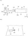
Fig. 1 is a side view of a liquid chemical administration system according to an embodiment. -
Fig. 2 is a view schematically showing a usage example of the liquid chemical administration system. -
Fig. 3 is a schematic perspective view of a liquid chemical administration device. -
Fig. 4 is a schematic perspective view of a chassis included in a housing, and each component member assembled to the chassis. -
Fig. 5 is a block diagram schematically showing a control system of the liquid chemical administration device. -
Fig. 6 is a flowchart schematically showing a control method for a liquid chemical administration device according to the embodiment. -
Fig. 7 is a plan view of the liquid chemical administration device, showing a state before a pusher moves forward. -
Fig. 8 is a plan view of the liquid chemical administration device, showing a state after the pusher moves forward. -
Fig. 9 is a view showing a positional relationship between the pusher and a detection unit. -
Fig. 10 is a plan view showing a contrast example. -
Fig. 11 is a plan view showing a contrast example. - Hereinafter, an embodiment of the present invention will be described with reference to the accompanying drawings. Note that the following description does not limit the technical scope or the meaning of terms used in the claims. Further, the dimensional ratios in the drawings are exaggerated for convenience of description, and may differ from the actual ratios.
-
Figs. 1 to 4 are views provided for explaining a liquidchemical administration system 10, a liquidchemical administration device 100, and anadministration tool 200 according to the embodiment.Fig. 5 is a block diagram schematically showing a control system of acontrol unit 160, andFig. 6 is a flowchart showing a control method for a liquid chemical administration device. Further,Figs. 7 to 8 are views for explaining an action of the liquidchemical administration device 100 and a comparative example. Arrow X attached to each figure indicates a "longitudinal direction (a longitudinal direction of a liquid chemical container 110)" of the liquidchemical administration device 100, arrow Y indicates a "width direction (a depth direction)" of the liquidchemical administration device 100, and arrow Z indicates a "height direction" of the liquidchemical administration device 100. - The liquid
chemical administration system 10 is used to administer a liquid chemical into a living body. As shown inFig. 1 , the liquidchemical administration system 10 includes the liquidchemical administration device 100 and theadministration tool 200. - As shown in
Fig. 2 , the liquidchemical administration device 100 and theadministration tool 200 are configured as a patch type that is used by being attached to a body surface (skin) H of a user. A body part of the user to be attached with the liquidchemical administration device 100 and theadministration tool 200 is not particularly limited, but is, for example, an abdomen or a thigh. - The liquid
chemical administration system 10 can continuously administer, for example, a liquid chemical (not shown) filled in the liquidchemical container 110 included in the liquidchemical administration device 100, into a living body over a relatively long time (for example, several minutes to several hours) through a pushing action of apusher 130 described later. Note that the liquidchemical administration system 10 may intermittently administer the liquid chemical into the living body. - As shown in
Figs. 3, 4 ,7, and 8 , the liquidchemical administration device 100 has the liquidchemical container 110 including a cylindrical (barrel-shaped)main body 111 filled with a liquid chemical, ahousing 120 that holds the liquidchemical container 110, thepusher 130 that pushes out the liquid chemical in the liquidchemical container 110, adrive mechanism 140 that advances thepusher 130 toward a distal end opening of the liquidchemical container 110, adetection unit 150 that detects adetection target part 134 of thepusher 130 and detects liquid supply completion of the liquid chemical based on a detection result, and thecontrol unit 160 that controls an operation of the drive mechanism. - As shown in
Figs. 3 and 4 , thehousing 120 has a box-shaped housingmain body 120a in which anaccommodation space 128 is internally formed, and a chassis (corresponding to a "supporting part") 127 that is accommodated in theaccommodation space 128 of the housingmain body 120a and can be fixed to the housingmain body 120a. - As shown in
Fig. 3 , on anupper surface 123 of the housingmain body 120a, there is formed awindow 123a that enables visual recognition of an inside of theaccommodation space 128 from an outside of thehousing 120. Thewindow 123a is formed by providing a transparent or semitransparent portion on a part of the housingmain body 120a. - On a base end side in the longitudinal direction of the housing
main body 120a, there is formed a base end opening 125 for insertion of thechassis 127 into theaccommodation space 128 of the housingmain body 120a. The base end opening 125 of the housingmain body 120a is closed by a lid member (not shown), with thechassis 127 accommodated in theaccommodation space 128. - A
bottom surface 121 of the housingmain body 120a is provided with a sheet-shaped sticking part (not shown) that can be stuck to the body surface H of the user. In an initial state before attaching the liquidchemical administration device 100 to the user, a releasable protective sheet is attached to a sticking surface of the sticking part. - As shown in
Fig. 4 , thechassis 127 holds the liquidchemical container 110, thepusher 130, thedrive mechanism 140, thedetection unit 150, thecontrol unit 160, and apower supply unit 170. - The liquid
chemical container 110 is configured by a so-called pre-filled liquid chemical container. Therefore, the liquid chemical is filled in advance in aninner cavity 111a of themain body 111 of the liquidchemical container 110. Examples of the liquid chemical include a protein preparation, a narcotic analgesic, a diuretic, and the like. - At a distal end opening (a discharge port) formed at a
distal end 112 of the liquidchemical container 110, a sealing member (not shown) to prevent leaking of the liquid chemical is arranged. As shown inFig. 3 , the distal end opening of the liquidchemical container 110 is arranged so as to externally project from the housingmain body 120a. Further, a mountingpart 115, which is to be connected to a tube 240 (seeFig. 1 ) described later, is attached to a distal end portion of theliquid chemical container 110 projecting from the housingmain body 120a. - A
main body 131 of thepusher 130 is inserted into theinner cavity 111a of themain body 111 of the liquid chemical container 110 (seeFigs. 4 and7 ). At a distal end of themain body 131 of thepusher 130, agasket 135 that is slidable with an inner wall of theliquid chemical container 110 is arranged. In thegasket 135, a base end side of thegasket 135 is liquid-tightly sealed, by an outer peripheral portion of thegasket 135 being in liquid-tight contact with an inner peripheral surface of themain body 111 of theliquid chemical container 110. - In the present embodiment, the
gasket 135 is configured to be able to contract in an advancement direction (the longitudinal direction) of thepusher 130, when thepusher 130 advances in a state where thegasket 135 abuts against a distal-endinner wall 112a (seeFig. 9 ) of theliquid chemical container 110. Thegasket 135 can be made by a flexible resin material such as, for example, a rubber material or an elastomer so as to be able to contract as described above. - As shown in
Fig. 9 , thegasket 135 has a tapered shape in which an outer diameter decreases toward a distal end side. Further, the shape of thegasket 135 is formed to be substantially the same as a shape of the distal-endinner wall 112a of theliquid chemical container 110. - As shown in
Fig. 9 , thedetection target part 134 is provided at a base end of thepusher 130. Thedetection target part 134 is used to detect liquid supply completion of the liquid chemical by the liquidchemical administration device 100. The method of detecting the liquid supply completion will be described later. - The
control unit 160 controls a liquid supply operation of the liquid chemical of the liquidchemical administration device 100. Thecontrol unit 160 can be configured by, for example, a known microcomputer (an electronic circuit element) mounted with a CPU, a RAM, a ROM, and the like. Thecontrol unit 160 centrally executes operation control of thedrive mechanism 140, thedetection unit 150, thepower supply unit 170, and a notification unit 180 (seeFig. 5 ). - As shown in
Fig. 7 , thedetection unit 150 is arranged on thechassis 127. As shown inFig. 8 , when thedetection target part 134 included in thepusher 130 comes into contact with thedetection unit 150, thedetection unit 150 detects liquid supply completion of the liquidchemical administration device 100. Thedetection unit 150 can be configured by, for example, a known contact sensor that emits a predetermined electric signal when thedetection target part 134 comes into contact with thedetection unit 150. Thecontrol unit 160 receives the electric signal from thedetection target part 134, to acquire information regarding the liquid supply completion. Note that thedetection unit 150 is not particularly limited in a specific configuration and the like as long as it is possible to detect a position of thedetection target part 134 of thepusher 130 when thepusher 130 advances by a predetermined amount. - The
power supply unit 170 can be configured by, for example, a known battery or the like. - The
notification unit 180 notifies the user of liquid supply completion. Thenotification unit 180 can be configured by, for example, a speaker or the like that emits voice or sound indicating that the liquid supply is completed. Thenotification unit 180 can be accommodated in theaccommodation space 128 of the housingmain body 120a. - As shown in
Fig. 4 , thedrive mechanism 140 has amotor 141 that receives a driving current from thepower supply unit 170 to generate a rotational driving force, areduction mechanism 143 including a gear or the like to transmit the rotational driving force of themotor 141, and afeed screw 147 connected to thereduction mechanism 143. - The
feed screw 147 is connected to a base-end connecting part 133 arranged near the base end of thepusher 130. Thefeed screw 147 converts a rotary motion transmitted from thereduction mechanism 143 into a linear motion, and advances thepusher 130 in the longitudinal direction (the X direction). Thepusher 130 pushes out the liquid chemical from theinner cavity 111a of themain body 111 of theliquid chemical container 110 to the tube 240 (seeFig. 1 ), by advancing toward the distal end side of theliquid chemical container 110. - Next, with reference to
Fig. 9 , a positional relationship between thedetection unit 150 and thedetection target part 134 will be described. Note thatFig. 9 shows theliquid chemical container 110 and thepusher 130 in a state before administering the liquid chemical. - In the present embodiment, the
detection unit 150 is arranged so as to detect liquid supply completion before adistal end 135a of thepusher 130 abuts against the distal-endinner wall 112a of theliquid chemical container 110. More specifically, as shown inFig. 9 , a first distance (d1) from thedistal end 135a of thepusher 130 to thedetection target part 134 is shorter than a second distance (d2) from the distal-endinner wall 112a of theliquid chemical container 110 to a position where thedetection unit 150 is arranged. Therefore, when thepusher 130 advances in theliquid chemical container 110 to cause thedetection target part 134 to come into contact with thedetection unit 150, and thedetection unit 150 detects liquid supply completion, there is formed a gap (space) in which thepusher 130 can further advance, between the distal-endinner wall 112a of theliquid chemical container 110 and thedistal end 135a of thepusher 130. - Note that the
distal end 135a of thepusher 130 means the distal end of thegasket 135 when thegasket 135 is arranged on thepusher 130 as in the present embodiment. - Next, a control method for the liquid
chemical administration device 100 according to the present embodiment will be described. Hereinafter, operation control of thepusher 130 at a time of liquid supply of a liquid chemical will be described in detail. - As shown in
Fig. 6 , the control method for the liquidchemical administration device 100 has a step of advancing thepusher 130 in the liquid chemical container 110 (S101), a step of detecting liquid supply completion by thedetection unit 150 detecting thedetection target part 134 of the pusher 130 (S102), and a step of advancing thepusher 130 after liquid supply completion is detected by the detection unit 150 (S103). -
Fig. 7 shows a state before thepusher 130 advances in theliquid chemical container 110. When thepusher 130 advances in theliquid chemical container 110 from the state shown inFig. 7 , and thedetection target part 134 comes into contact with thedetection unit 150 as shown inFig. 8 , thedetection unit 150 detects the liquid supply completion. - In the control method according to the present embodiment, after the liquid supply completion is detected as described above, the
pusher 130 is further advanced by a distance equal to or more than a distance until thedistal end 135a of thepusher 130 abuts against the distal-endinner wall 112a of theliquid chemical container 110. This is for the following reason. - For example, in the liquid
chemical administration device 100, if there is a deviation in installation accuracy of thedetection unit 150, thepusher 130, theliquid chemical container 110, and the like, or dimensional accuracy of thepusher 130, theliquid chemical container 110, and the like, as shown inFigure 10 , thedetection unit 150 detects liquid supply completion despite being in a state where the liquid chemical remains in the liquid chemical container 110 (a state where thedistal end 135a of thepusher 130 is not in contact with the distal-endinner wall 112a of the liquid chemical container 110). If the liquid supply by the liquidchemical administration device 100 ends as it is, it becomes impossible to administer an amount of the liquid chemical that should be originally administered to the living body. With respect to such a problem, the liquidchemical administration device 100 according to the present embodiment further advances thepusher 130 after thedetection unit 150 detects the liquid supply completion. Therefore, the liquidchemical administration device 100 can preferably prevent occurrence of "remaining of the liquid chemical" due to a deviation or the like in installation accuracy or dimensional accuracy of each member. Particularly, in the present embodiment, it is possible to more reliably prevent the liquid chemical from remaining in theliquid chemical container 110 since thepusher 130 is advanced by a distance equal to or more than a distance until thedistal end 135a of thepusher 130 abuts against the distal-endinner wall 112a of theliquid chemical container 110 after the liquid supply completion is detected. - Further, if there is a deviation or the like in installation accuracy or dimensional accuracy of each member, as shown in
Fig. 11 , there may also be a problem that thedetection unit 150 does not detect the liquid supply completion although thepusher 130 has advanced until thedistal end 135a of thepusher 130 abuts against the distal-endinner wall 112a of theliquid chemical container 110. For such a problem, thegasket 135 included in thepusher 130 according to the present embodiment is configured to be able to contract in a state of abutting against the distal-endinner wall 112a of theliquid chemical container 110, in an advancement direction (the longitudinal direction) of thepusher 130 when thepusher 130 advances. Therefore, the liquidchemical administration device 100 can further advance thepusher 130 by an amount of contraction of thegasket 135, even if the state shown inFig. 11 is made to cause a situation where the advancement of thepusher 130 does not proceed. Therefore, in the liquidchemical administration device 100, thedetection unit 150 can reliably detect the liquid supply completion. - Note that a timing for ending the advancement of the
pusher 130 and a timing for notifying the liquid supply completion may be set at any timing, for example, after a predetermined time has elapsed after thedetection unit 150 detects the liquid supply completion. Further, the advancement of thepusher 130 may be continued until the liquidchemical administration device 100 is removed from the living body, or may be continued as it is after the liquid supply is completed. - As shown in
Figs. 1 and 2 , theadministration tool 200 is configured to be connectable to the liquidchemical administration device 100. - The
administration tool 200 has aconnector 210, aneedle tube 220 that is punctured into a living body, a puncture part (a cannula housing) 230, thetube 240, and apuncture assisting tool 250 that assists puncture of theneedle tube 220 into the living body. - The
connector 210 is configured to be connectable to the liquidchemical administration device 100 via a mountingpart 215 fixed to theconnector 210. The mountingpart 215 can be connected to the liquidchemical administration device 100 by being externally fitted to the mounting part 115 (seeFig. 4 ) provided near thedistal end 112 of theliquid chemical container 110 projecting to an outside of thehousing 120. - Inside the mounting
part 215, there is arranged a connecting needle part (not shown) capable of puncturing a sealing member (not shown) arranged at the distal end portion of theliquid chemical container 110. Thetube 240 communicates with theinner cavity 111a of themain body 111 of theliquid chemical container 110 via the connecting needle part. - Inside the
puncture part 230, a flow path (not shown) that connects thetube 240 and an inner cavity of theneedle tube 220 is formed. A liquid chemical supplied to thepuncture part 230 via thetube 240 is administered into the living body through the flow path formed inside thepuncture part 230 and theneedle tube 220. - The
puncture assisting tool 250 is attached to thepuncture part 230 at a time of liquid supply of the liquid chemical to the user. Thepuncture assisting tool 250 holds an introduction needle (an inner needle) 251. Theintroduction needle 251 projects from a distal end of theneedle tube 220, with thepuncture assisting tool 250 attached to thepuncture part 230. By puncturing theneedle tube 220 into the living body with theintroduction needle 251 inserted through theneedle tube 220, the user can insert theneedle tube 220 into a living body while preventing breakage or the like of theneedle tube 220. - The
puncture assisting tool 250 is removed from thepuncture part 230 after theneedle tube 220 is punctured into the living body. Theintroduction needle 251 is extracted from the inner cavity of theneedle tube 220 when thepuncture assisting tool 250 is removed from thepuncture part 230. - After the
needle tube 220 is punctured into the living body, thepuncture assisting tool 250 is removed, and thepuncture part 230 is left on the body surface H of the user with theneedle tube 220 placed in the living body. In this state, as thepusher 130 of the liquidchemical administration device 100 advances in theliquid chemical container 110, the liquid chemical filled in theliquid chemical container 110 is supplied to the inner cavity of theneedle tube 220 via thetube 240 and the flow path of thepuncture part 230. - The
introduction needle 251 can be configured by, for example, a metal needle. Further, theneedle tube 220 can be configured by, for example, a resin tubular member (a cannula). - The
administration tool 200 is configured as a patch type to be used by being attached to the body surface H of the user, similarly to the liquidchemical administration device 100. A contact surface (a bottom surface) 231 of thepuncture part 230 of theadministration tool 200 is provided with a sheet-shaped sticking part (not shown) that can be stuck to the body surface. In an initial state before attaching theadministration tool 200 to the user, a releasable protective sheet is attached to a sticking surface of the sticking part. - As described above, the liquid
chemical administration device 100 according to the present embodiment has theliquid chemical container 110 filled with a liquid chemical and having the distal end opening at thedistal end 112, thehousing 120 that holds theliquid chemical container 110, thepusher 130 that pushes out the liquid chemical in theliquid chemical container 110, thedrive mechanism 140 that advances thepusher 130 toward the distal end opening of theliquid chemical container 110, thedetection unit 150 that detects thedetection target part 134 of thepusher 130 and detects liquid supply completion of the liquid chemical based on a detection result, and thecontrol unit 160 that controls an operation of thedrive mechanism 140. Thecontrol unit 160 further advances thepusher 130 after thedetection unit 150 detects the liquid supply completion. - According to the liquid
chemical administration device 100 configured as described above, it is possible to prevent advancement of thepusher 130 from ending in a state where the liquid chemical remains in theliquid chemical container 110, since thepusher 130 is further advanced after liquid supply completion is detected by thedetection unit 150. Therefore, it is possible to prevent liquid supply of the liquid chemical from ending in a state where the liquid chemical remains in theliquid chemical container 110. - Further, in the liquid
chemical administration device 100, thedetection unit 150 is arranged so as to detect liquid supply completion before thedistal end 135a of thepusher 130 abuts against the distal-endinner wall 112a of theliquid chemical container 110. Furthermore, thecontrol unit 160 advances thepusher 130 by a distance equal to or more than a distance until thedistal end 135a of thepusher 130 abuts against the distal-endinner wall 112a of theliquid chemical container 110 after thedetection unit 150 detects the liquid supply completion. Therefore, the liquidchemical administration device 100 can more reliably prevent liquid supply of the liquid chemical from ending in a state where the liquid chemical remains in theliquid chemical container 110. - Further, in the liquid
chemical administration device 100, the first distance (d1) from thedistal end 135a of thepusher 130 to thedetection target part 134 is shorter than the second distance (d2) from the distal-endinner wall 112a of theliquid chemical container 110 to the position where thedetection unit 150 is arranged. Therefore, thedetection unit 150 can reliably detect liquid supply completion before thedistal end 135a of thepusher 130 abuts against the distal-endinner wall 112a of theliquid chemical container 110. Therefore, by further advancing thepusher 130 after detecting the liquid supply completion, it is possible to more reliably prevent liquid supply of the liquid chemical from ending in a state where the liquid chemical remains in theliquid chemical container 110. - Further, in the liquid
chemical administration device 100, thegasket 135 slidable with respect to the inner wall of theliquid chemical container 110 is arranged at thedistal end 135a of thepusher 130. Further, when thepusher 130 advances, thegasket 135 can contract in a state of abutting against the distal-endinner wall 112a of theliquid chemical container 110, in an advancement direction of thepusher 130. Therefore, thepusher 130 can be further advanced by an amount of contraction of thegasket 135, even in a state where thegasket 135 abuts against the distal-endinner wall 112a of theliquid chemical container 110 and a state where liquid supply completion is not detected by thedetection unit 150. Therefore, the liquidchemical administration device 100 can more reliably detect the liquid supply completion. - Further, the control method for the liquid
chemical administration device 100 according to the present embodiment is a control method for controlling movement of thepusher 130 in the liquidchemical administration device 100 including theliquid chemical container 110 filled with a liquid chemical and having the distal end opening at thedistal end 112, thehousing 120 that holds theliquid chemical container 110, thepusher 130 that pushes out the liquid chemical in theliquid chemical container 110, thedrive mechanism 140 that advances thepusher 130 toward the distal end opening of theliquid chemical container 110, thedetection unit 150 that detects thedetection target part 134 of thepusher 130 and detects liquid supply completion of the liquid chemical based on a detection result, and thecontrol unit 160 that controls an operation of thedrive mechanism 140. In the control method, thecontrol unit 160 further advances thepusher 130 after thedetection unit 150 detects the liquid supply completion. - According to the above control method, since the
pusher 130 is further advanced after liquid supply completion is detected by thedetection unit 150, it is possible to prevent advancement of thepusher 130 from ending in a state where the liquid chemical remains in theliquid chemical container 110. Therefore, it is possible to prevent liquid supply of the liquid chemical from ending in a state where the liquid chemical remains in theliquid chemical container 110. - The liquid
chemical administration device 100 can also be configured to determine an administration state, for example, on the basis of a detection result of a rotation state of themotor 141 and on the basis of detection of liquid supply completion based on contact between thedetection unit 150 and thedetection target part 134 of thepusher 130. Specifically, thecontrol unit 160 can be configured to determine the administration state of the liquidchemical administration device 100 with the following control flow. - When rotation stop of the
motor 141 is detected by a rotation detection mechanism (not shown), thecontrol unit 160 confirms detection of liquid supply completion based on contact between thedetection target part 134 of thepusher 130 and thedetection unit 150. Note that, when themotor 141 is stopped, thedistal end 135a of thepusher 130 is in a state of abutting against the distal-endinner wall 112a of the liquid chemical container 110 (the state shown inFig. 11 ). Therefore, after thedetection unit 150 detects the liquid supply completion, thecontrol unit 160 advances thepusher 130 until the rotation detection mechanism detects a stop of the rotation of themotor 141. Then, when themotor 141 is stopped, thecontrol unit 160 determines that administration of the liquid chemical has ended normally, when confirming the liquid supply completion based on contact between thedetection target part 134 of thepusher 130 and the detection unit 150 (when thepusher 130 and thedetection unit 150 are in a contact state). Whereas, when themotor 141 is stopped, thecontrol unit 160 determines that administration of the liquid chemical has not ended normally (that is, the administration of the liquid chemical has ended with the residual liquid remaining in the liquid chemical container 110), when confirming no detection of liquid supply completion based on contact between thedetection target part 134 of thepusher 130 and the detection unit 150 (when thepusher 130 and thedetection unit 150 are in a noncontact state). When thecontrol unit 160 confirms that the administration of the liquid chemical has not been normally performed, thecontrol unit 160 can notify that effect by thenotification unit 180. - As described above, the liquid chemical administration device and the control method for the liquid chemical administration device according to the present invention have been described through the embodiment. However, the present invention is not limited to each configuration described above, but can be modified as appropriate based on the description of the claims.
- For example, for the control unit, a specific control method, control procedure, and the like are not particularly limited as long as an operation is controlled to further advance the pusher after the detection unit detects liquid supply completion. Further, the housing may be configured such that each component member is fixed or held in the housing main body without including the chassis.
- Further, a material, a shape, a size, arrangement, a connection/coupling structure between members, and the like of each member included in the liquid chemical administration device can be freely changed and replaced without limitation as long as the effects of the present invention are exhibited. Further, it is possible to appropriately add any component members and the like not particularly described in the specification, to the liquid chemical administration device.
- This application is based on Japanese Patent Application
2018-067431, filed on March 30, 2018 -
- 10 Liquid chemical administration system,
- 100 liquid chemical administration device,
- 110 liquid chemical container,
- 111 main body of liquid chemical container,
- 111a inner cavity of liquid chemical container,
- 112a distal-end inner wall of liquid chemical container,
- 120 housing,
- 120a housing main body,
- 127 chassis,
- 128 accommodation space,
- 130 pusher,
- 131 main body of pusher,
- 134 detection target part,
- 135 gasket,
- 135a distal end of pusher,
- 140 drive mechanism,
- 150 detection unit,
- 160 control unit,
- 170 power supply unit,
- 180 notification unit,
- 200 administration tool,
- H body surface.
Claims (5)
- A liquid chemical administration device comprising:a liquid chemical container filled with a liquid chemical and having a distal end opening at a distal end;a housing that holds the liquid chemical container;a pusher that pushes out the liquid chemical in the liquid chemical container;a drive mechanism that advances the pusher toward the distal end opening of the liquid chemical container;a detection unit that detects a detection target part of the pusher and detects liquid supply completion of the liquid chemical based on a detection result; anda control unit that controls an operation of the drive mechanism, whereinthe control unit further advances the pusher after the detection unit detects the liquid supply completion.
- The liquid chemical administration device according to claim 1, wherein
the detection unit is arranged to detect the liquid supply completion before a distal end of the pusher abuts against a distal-end inner wall of the liquid chemical container, and
after the detection unit detects the liquid supply completion, the control unit advances the pusher by a distance equal to or more than a distance until the distal end of the pusher abuts against the distal-end inner wall of the liquid chemical container. - The liquid chemical administration device according to claim 2, wherein a first distance from the distal end of the pusher to the detection target part is shorter than a second distance from the distal-end inner wall of the liquid chemical container to a position where the detection unit is arranged.
- The liquid chemical administration device according to any one of claims 1 to 3, wherein
a gasket slidable with respect to an inner wall of the liquid chemical container is arranged at the distal end of the pusher, and
when the pusher advances, the gasket can contract in a state of abutting against the distal-end inner wall of the liquid chemical container, in an advancement direction of the pusher. - A control method for a liquid chemical administration device, the control method being for controlling movement of a pusher in a liquid chemical administration device comprising: a liquid chemical container filled with a liquid chemical and having a distal end opening at a distal end; a housing that holds the liquid chemical container; the pusher that pushes out the liquid chemical in the liquid chemical container; a drive mechanism that advances the pusher toward the distal end opening of the liquid chemical container; a detection unit that detects a detection target part of the pusher and detects liquid supply completion of the liquid chemical based on a detection result; and a control unit that controls an operation of the drive mechanism, wherein
the control unit further advances the pusher after the detection unit detects the liquid supply completion.
Applications Claiming Priority (2)
| Application Number | Priority Date | Filing Date | Title |
|---|---|---|---|
| JP2018067431 | 2018-03-30 | ||
| PCT/JP2019/013893 WO2019189703A1 (en) | 2018-03-30 | 2019-03-28 | Drug solution administration device and control method of drug solution administration device |
Publications (2)
| Publication Number | Publication Date |
|---|---|
| EP3760248A1 true EP3760248A1 (en) | 2021-01-06 |
| EP3760248A4 EP3760248A4 (en) | 2021-03-03 |
Family
ID=68059088
Family Applications (1)
| Application Number | Title | Priority Date | Filing Date |
|---|---|---|---|
| EP19775879.0A Pending EP3760248A4 (en) | 2018-03-30 | 2019-03-28 | Drug solution administration device and control method of drug solution administration device |
Country Status (4)
| Country | Link |
|---|---|
| US (1) | US20210008274A1 (en) |
| EP (1) | EP3760248A4 (en) |
| JP (1) | JP7162055B2 (en) |
| WO (1) | WO2019189703A1 (en) |
Families Citing this family (1)
| Publication number | Priority date | Publication date | Assignee | Title |
|---|---|---|---|---|
| CN114845754B (en) * | 2020-03-25 | 2025-10-28 | 泰尔茂株式会社 | Drug administration device |
Family Cites Families (15)
| Publication number | Priority date | Publication date | Assignee | Title |
|---|---|---|---|---|
| DE3314664C2 (en) * | 1983-04-22 | 1985-02-21 | B. Braun Melsungen Ag, 3508 Melsungen | Procedure for triggering a pre-alarm in a pressure infusion apparatus |
| JPS59228851A (en) * | 1983-06-09 | 1984-12-22 | アトム株式会社 | Transfusion apparatus |
| JPH02121672A (en) * | 1988-11-01 | 1990-05-09 | Nikkiso Co Ltd | Syringe injection device |
| US5254096A (en) * | 1992-09-23 | 1993-10-19 | Becton, Dickinson And Company | Syringe pump with graphical display or error conditions |
| DE4339528C2 (en) * | 1993-11-19 | 1995-09-07 | Freudenberg Carl Fa | Disposable syringe |
| JP4208038B2 (en) | 1996-05-01 | 2009-01-14 | 成 額田 | Syringe |
| US7193521B2 (en) * | 1998-10-29 | 2007-03-20 | Medtronic Minimed, Inc. | Method and apparatus for detecting errors, fluid pressure, and occlusions in an ambulatory infusion pump |
| JP2000350782A (en) * | 1999-06-10 | 2000-12-19 | Terumo Corp | Syringe pump and injecting method |
| DE202007005394U1 (en) * | 2007-04-13 | 2007-08-09 | B. Braun Melsungen Ag | safety syringe |
| GB0822935D0 (en) * | 2008-12-17 | 2009-01-21 | Surgical Systems Ireland Ltd | A syringe driver |
| US9744300B2 (en) * | 2011-12-21 | 2017-08-29 | Deka Products Limited Partnership | Syringe pump and related method |
| CN106659852A (en) * | 2014-07-09 | 2017-05-10 | 诺和诺德股份有限公司 | Motorized drug delivery device |
| US9879668B2 (en) * | 2015-06-22 | 2018-01-30 | Medtronic Minimed, Inc. | Occlusion detection techniques for a fluid infusion device having a rotary pump mechanism and an optical sensor |
| JOP20170042B1 (en) * | 2016-02-12 | 2022-09-15 | Amgen Inc | Means of drug delivery, method of manufacture and method of use |
| JP6675293B2 (en) | 2016-10-18 | 2020-04-01 | 矢崎総業株式会社 | Manufacturing support method and manufacturing support program |
-
2019
- 2019-03-28 WO PCT/JP2019/013893 patent/WO2019189703A1/en not_active Ceased
- 2019-03-28 EP EP19775879.0A patent/EP3760248A4/en active Pending
- 2019-03-28 JP JP2020511057A patent/JP7162055B2/en active Active
-
2020
- 2020-09-29 US US17/037,181 patent/US20210008274A1/en not_active Abandoned
Also Published As
| Publication number | Publication date |
|---|---|
| JPWO2019189703A1 (en) | 2021-04-01 |
| JP7162055B2 (en) | 2022-10-27 |
| EP3760248A4 (en) | 2021-03-03 |
| WO2019189703A1 (en) | 2019-10-03 |
| US20210008274A1 (en) | 2021-01-14 |
Similar Documents
| Publication | Publication Date | Title |
|---|---|---|
| EP3612252B1 (en) | Insulin leakage sensor with electric control to stop insulin flow | |
| EP3260148B1 (en) | Liquid drug administration device | |
| US20170232192A1 (en) | Drug solution administration apparatus | |
| EP3925645A1 (en) | Liquid medicine administration apparatus | |
| EP3760249B1 (en) | Drug solution administration device | |
| US12296143B2 (en) | Liquid medicine administration device | |
| JP7162055B2 (en) | Chemical-solution administration device and control method for chemical-solution administration device | |
| EP3925646B1 (en) | Liquid medicine administration device and liquid medicine administration set | |
| EP3932450A1 (en) | Liquid medicine administration apparatus | |
| JP7641269B2 (en) | Drug administration device | |
| EP3925648B1 (en) | Liquid medicine administration apparatus | |
| JP2019176938A (en) | Medical fluid dispenser | |
| WO2026014109A1 (en) | Drug solution administration device, method for controlling same, and program |
Legal Events
| Date | Code | Title | Description |
|---|---|---|---|
| STAA | Information on the status of an ep patent application or granted ep patent |
Free format text: STATUS: THE INTERNATIONAL PUBLICATION HAS BEEN MADE |
|
| PUAI | Public reference made under article 153(3) epc to a published international application that has entered the european phase |
Free format text: ORIGINAL CODE: 0009012 |
|
| STAA | Information on the status of an ep patent application or granted ep patent |
Free format text: STATUS: REQUEST FOR EXAMINATION WAS MADE |
|
| 17P | Request for examination filed |
Effective date: 20201001 |
|
| AK | Designated contracting states |
Kind code of ref document: A1 Designated state(s): AL AT BE BG CH CY CZ DE DK EE ES FI FR GB GR HR HU IE IS IT LI LT LU LV MC MK MT NL NO PL PT RO RS SE SI SK SM TR |
|
| AX | Request for extension of the european patent |
Extension state: BA ME |
|
| A4 | Supplementary search report drawn up and despatched |
Effective date: 20210202 |
|
| RIC1 | Information provided on ipc code assigned before grant |
Ipc: A61M 5/168 20060101ALI20210127BHEP Ipc: A61M 5/145 20060101ALI20210127BHEP Ipc: A61M 5/142 20060101AFI20210127BHEP |
|
| DAV | Request for validation of the european patent (deleted) | ||
| DAX | Request for extension of the european patent (deleted) | ||
| STAA | Information on the status of an ep patent application or granted ep patent |
Free format text: STATUS: EXAMINATION IS IN PROGRESS |
|
| 17Q | First examination report despatched |
Effective date: 20240618 |