EP3760171B1 - Thermotherapy device - Google Patents
Thermotherapy device Download PDFInfo
- Publication number
- EP3760171B1 EP3760171B1 EP19760472.1A EP19760472A EP3760171B1 EP 3760171 B1 EP3760171 B1 EP 3760171B1 EP 19760472 A EP19760472 A EP 19760472A EP 3760171 B1 EP3760171 B1 EP 3760171B1
- Authority
- EP
- European Patent Office
- Prior art keywords
- ceramics
- supporting plate
- heater
- thermotherapy device
- disposed
- Prior art date
- Legal status (The legal status is an assumption and is not a legal conclusion. Google has not performed a legal analysis and makes no representation as to the accuracy of the status listed.)
- Active
Links
Images


Classifications
-
- A—HUMAN NECESSITIES
- A61—MEDICAL OR VETERINARY SCIENCE; HYGIENE
- A61F—FILTERS IMPLANTABLE INTO BLOOD VESSELS; PROSTHESES; DEVICES PROVIDING PATENCY TO, OR PREVENTING COLLAPSING OF, TUBULAR STRUCTURES OF THE BODY, e.g. STENTS; ORTHOPAEDIC, NURSING OR CONTRACEPTIVE DEVICES; FOMENTATION; TREATMENT OR PROTECTION OF EYES OR EARS; BANDAGES, DRESSINGS OR ABSORBENT PADS; FIRST-AID KITS
- A61F7/00—Heating or cooling appliances for medical or therapeutic treatment of the human body
- A61F7/007—Heating or cooling appliances for medical or therapeutic treatment of the human body characterised by electric heating
-
- A—HUMAN NECESSITIES
- A61—MEDICAL OR VETERINARY SCIENCE; HYGIENE
- A61H—PHYSICAL THERAPY APPARATUS, e.g. DEVICES FOR LOCATING OR STIMULATING REFLEX POINTS IN THE BODY; ARTIFICIAL RESPIRATION; MASSAGE; BATHING DEVICES FOR SPECIAL THERAPEUTIC OR HYGIENIC PURPOSES OR SPECIFIC PARTS OF THE BODY
- A61H1/00—Apparatus for passive exercising; Vibrating apparatus; Chiropractic devices, e.g. body impacting devices, external devices for briefly extending or aligning unbroken bones
-
- A—HUMAN NECESSITIES
- A61—MEDICAL OR VETERINARY SCIENCE; HYGIENE
- A61H—PHYSICAL THERAPY APPARATUS, e.g. DEVICES FOR LOCATING OR STIMULATING REFLEX POINTS IN THE BODY; ARTIFICIAL RESPIRATION; MASSAGE; BATHING DEVICES FOR SPECIAL THERAPEUTIC OR HYGIENIC PURPOSES OR SPECIFIC PARTS OF THE BODY
- A61H23/00—Percussion or vibration massage, e.g. using supersonic vibration; Suction-vibration massage; Massage with moving diaphragms
- A61H23/02—Percussion or vibration massage, e.g. using supersonic vibration; Suction-vibration massage; Massage with moving diaphragms with electric or magnetic drive
-
- A—HUMAN NECESSITIES
- A61—MEDICAL OR VETERINARY SCIENCE; HYGIENE
- A61H—PHYSICAL THERAPY APPARATUS, e.g. DEVICES FOR LOCATING OR STIMULATING REFLEX POINTS IN THE BODY; ARTIFICIAL RESPIRATION; MASSAGE; BATHING DEVICES FOR SPECIAL THERAPEUTIC OR HYGIENIC PURPOSES OR SPECIFIC PARTS OF THE BODY
- A61H23/00—Percussion or vibration massage, e.g. using supersonic vibration; Suction-vibration massage; Massage with moving diaphragms
- A61H23/02—Percussion or vibration massage, e.g. using supersonic vibration; Suction-vibration massage; Massage with moving diaphragms with electric or magnetic drive
- A61H23/0254—Percussion or vibration massage, e.g. using supersonic vibration; Suction-vibration massage; Massage with moving diaphragms with electric or magnetic drive with rotary motor
- A61H23/0263—Percussion or vibration massage, e.g. using supersonic vibration; Suction-vibration massage; Massage with moving diaphragms with electric or magnetic drive with rotary motor using rotating unbalanced masses
-
- A—HUMAN NECESSITIES
- A61—MEDICAL OR VETERINARY SCIENCE; HYGIENE
- A61H—PHYSICAL THERAPY APPARATUS, e.g. DEVICES FOR LOCATING OR STIMULATING REFLEX POINTS IN THE BODY; ARTIFICIAL RESPIRATION; MASSAGE; BATHING DEVICES FOR SPECIAL THERAPEUTIC OR HYGIENIC PURPOSES OR SPECIFIC PARTS OF THE BODY
- A61H39/00—Devices for locating or stimulating specific reflex points of the body for physical therapy, e.g. acupuncture
-
- A—HUMAN NECESSITIES
- A61—MEDICAL OR VETERINARY SCIENCE; HYGIENE
- A61H—PHYSICAL THERAPY APPARATUS, e.g. DEVICES FOR LOCATING OR STIMULATING REFLEX POINTS IN THE BODY; ARTIFICIAL RESPIRATION; MASSAGE; BATHING DEVICES FOR SPECIAL THERAPEUTIC OR HYGIENIC PURPOSES OR SPECIFIC PARTS OF THE BODY
- A61H39/00—Devices for locating or stimulating specific reflex points of the body for physical therapy, e.g. acupuncture
- A61H39/007—Stimulation by mechanical vibrations, e.g. ultrasonic
-
- A—HUMAN NECESSITIES
- A61—MEDICAL OR VETERINARY SCIENCE; HYGIENE
- A61H—PHYSICAL THERAPY APPARATUS, e.g. DEVICES FOR LOCATING OR STIMULATING REFLEX POINTS IN THE BODY; ARTIFICIAL RESPIRATION; MASSAGE; BATHING DEVICES FOR SPECIAL THERAPEUTIC OR HYGIENIC PURPOSES OR SPECIFIC PARTS OF THE BODY
- A61H39/00—Devices for locating or stimulating specific reflex points of the body for physical therapy, e.g. acupuncture
- A61H39/04—Devices for pressing such points, e.g. Shiatsu or Acupressure
-
- A—HUMAN NECESSITIES
- A61—MEDICAL OR VETERINARY SCIENCE; HYGIENE
- A61H—PHYSICAL THERAPY APPARATUS, e.g. DEVICES FOR LOCATING OR STIMULATING REFLEX POINTS IN THE BODY; ARTIFICIAL RESPIRATION; MASSAGE; BATHING DEVICES FOR SPECIAL THERAPEUTIC OR HYGIENIC PURPOSES OR SPECIFIC PARTS OF THE BODY
- A61H39/00—Devices for locating or stimulating specific reflex points of the body for physical therapy, e.g. acupuncture
- A61H39/06—Devices for heating or cooling such points within cell-life limits
-
- A—HUMAN NECESSITIES
- A61—MEDICAL OR VETERINARY SCIENCE; HYGIENE
- A61H—PHYSICAL THERAPY APPARATUS, e.g. DEVICES FOR LOCATING OR STIMULATING REFLEX POINTS IN THE BODY; ARTIFICIAL RESPIRATION; MASSAGE; BATHING DEVICES FOR SPECIAL THERAPEUTIC OR HYGIENIC PURPOSES OR SPECIFIC PARTS OF THE BODY
- A61H7/00—Devices for suction-kneading massage; Devices for massaging the skin by rubbing or brushing not otherwise provided for
- A61H7/007—Kneading
-
- A—HUMAN NECESSITIES
- A61—MEDICAL OR VETERINARY SCIENCE; HYGIENE
- A61N—ELECTROTHERAPY; MAGNETOTHERAPY; RADIATION THERAPY; ULTRASOUND THERAPY
- A61N5/00—Radiation therapy
- A61N5/06—Radiation therapy using light
- A61N5/0613—Apparatus adapted for a specific treatment
- A61N5/0625—Warming the body, e.g. hyperthermia treatment
-
- A—HUMAN NECESSITIES
- A61—MEDICAL OR VETERINARY SCIENCE; HYGIENE
- A61F—FILTERS IMPLANTABLE INTO BLOOD VESSELS; PROSTHESES; DEVICES PROVIDING PATENCY TO, OR PREVENTING COLLAPSING OF, TUBULAR STRUCTURES OF THE BODY, e.g. STENTS; ORTHOPAEDIC, NURSING OR CONTRACEPTIVE DEVICES; FOMENTATION; TREATMENT OR PROTECTION OF EYES OR EARS; BANDAGES, DRESSINGS OR ABSORBENT PADS; FIRST-AID KITS
- A61F7/00—Heating or cooling appliances for medical or therapeutic treatment of the human body
- A61F2007/0001—Body part
- A61F2007/0018—Trunk or parts thereof
- A61F2007/0022—Abdomen
-
- A—HUMAN NECESSITIES
- A61—MEDICAL OR VETERINARY SCIENCE; HYGIENE
- A61F—FILTERS IMPLANTABLE INTO BLOOD VESSELS; PROSTHESES; DEVICES PROVIDING PATENCY TO, OR PREVENTING COLLAPSING OF, TUBULAR STRUCTURES OF THE BODY, e.g. STENTS; ORTHOPAEDIC, NURSING OR CONTRACEPTIVE DEVICES; FOMENTATION; TREATMENT OR PROTECTION OF EYES OR EARS; BANDAGES, DRESSINGS OR ABSORBENT PADS; FIRST-AID KITS
- A61F7/00—Heating or cooling appliances for medical or therapeutic treatment of the human body
- A61F7/02—Compresses or poultices for effecting heating or cooling
- A61F2007/0225—Compresses or poultices for effecting heating or cooling connected to the body or a part thereof
- A61F2007/0228—Compresses or poultices for effecting heating or cooling connected to the body or a part thereof with belt or strap, e.g. with buckle
-
- A—HUMAN NECESSITIES
- A61—MEDICAL OR VETERINARY SCIENCE; HYGIENE
- A61H—PHYSICAL THERAPY APPARATUS, e.g. DEVICES FOR LOCATING OR STIMULATING REFLEX POINTS IN THE BODY; ARTIFICIAL RESPIRATION; MASSAGE; BATHING DEVICES FOR SPECIAL THERAPEUTIC OR HYGIENIC PURPOSES OR SPECIFIC PARTS OF THE BODY
- A61H39/00—Devices for locating or stimulating specific reflex points of the body for physical therapy, e.g. acupuncture
- A61H2039/005—Devices for locating or stimulating specific reflex points of the body for physical therapy, e.g. acupuncture by means of electromagnetic waves, e.g. I.R., U.V. rays
-
- A—HUMAN NECESSITIES
- A61—MEDICAL OR VETERINARY SCIENCE; HYGIENE
- A61H—PHYSICAL THERAPY APPARATUS, e.g. DEVICES FOR LOCATING OR STIMULATING REFLEX POINTS IN THE BODY; ARTIFICIAL RESPIRATION; MASSAGE; BATHING DEVICES FOR SPECIAL THERAPEUTIC OR HYGIENIC PURPOSES OR SPECIFIC PARTS OF THE BODY
- A61H2201/00—Characteristics of apparatus not provided for in the preceding codes
- A61H2201/01—Constructive details
- A61H2201/0157—Constructive details portable
-
- A—HUMAN NECESSITIES
- A61—MEDICAL OR VETERINARY SCIENCE; HYGIENE
- A61H—PHYSICAL THERAPY APPARATUS, e.g. DEVICES FOR LOCATING OR STIMULATING REFLEX POINTS IN THE BODY; ARTIFICIAL RESPIRATION; MASSAGE; BATHING DEVICES FOR SPECIAL THERAPEUTIC OR HYGIENIC PURPOSES OR SPECIFIC PARTS OF THE BODY
- A61H2201/00—Characteristics of apparatus not provided for in the preceding codes
- A61H2201/01—Constructive details
- A61H2201/0165—Damping, vibration related features
-
- A—HUMAN NECESSITIES
- A61—MEDICAL OR VETERINARY SCIENCE; HYGIENE
- A61H—PHYSICAL THERAPY APPARATUS, e.g. DEVICES FOR LOCATING OR STIMULATING REFLEX POINTS IN THE BODY; ARTIFICIAL RESPIRATION; MASSAGE; BATHING DEVICES FOR SPECIAL THERAPEUTIC OR HYGIENIC PURPOSES OR SPECIFIC PARTS OF THE BODY
- A61H2201/00—Characteristics of apparatus not provided for in the preceding codes
- A61H2201/01—Constructive details
- A61H2201/0165—Damping, vibration related features
- A61H2201/0169—Noise reduction
-
- A—HUMAN NECESSITIES
- A61—MEDICAL OR VETERINARY SCIENCE; HYGIENE
- A61H—PHYSICAL THERAPY APPARATUS, e.g. DEVICES FOR LOCATING OR STIMULATING REFLEX POINTS IN THE BODY; ARTIFICIAL RESPIRATION; MASSAGE; BATHING DEVICES FOR SPECIAL THERAPEUTIC OR HYGIENIC PURPOSES OR SPECIFIC PARTS OF THE BODY
- A61H2201/00—Characteristics of apparatus not provided for in the preceding codes
- A61H2201/02—Characteristics of apparatus not provided for in the preceding codes heated or cooled
- A61H2201/0207—Characteristics of apparatus not provided for in the preceding codes heated or cooled heated
-
- A—HUMAN NECESSITIES
- A61—MEDICAL OR VETERINARY SCIENCE; HYGIENE
- A61H—PHYSICAL THERAPY APPARATUS, e.g. DEVICES FOR LOCATING OR STIMULATING REFLEX POINTS IN THE BODY; ARTIFICIAL RESPIRATION; MASSAGE; BATHING DEVICES FOR SPECIAL THERAPEUTIC OR HYGIENIC PURPOSES OR SPECIFIC PARTS OF THE BODY
- A61H2201/00—Characteristics of apparatus not provided for in the preceding codes
- A61H2201/02—Characteristics of apparatus not provided for in the preceding codes heated or cooled
- A61H2201/0221—Mechanism for heating or cooling
- A61H2201/0228—Mechanism for heating or cooling heated by an electric resistance element
-
- A—HUMAN NECESSITIES
- A61—MEDICAL OR VETERINARY SCIENCE; HYGIENE
- A61H—PHYSICAL THERAPY APPARATUS, e.g. DEVICES FOR LOCATING OR STIMULATING REFLEX POINTS IN THE BODY; ARTIFICIAL RESPIRATION; MASSAGE; BATHING DEVICES FOR SPECIAL THERAPEUTIC OR HYGIENIC PURPOSES OR SPECIFIC PARTS OF THE BODY
- A61H2201/00—Characteristics of apparatus not provided for in the preceding codes
- A61H2201/10—Characteristics of apparatus not provided for in the preceding codes with further special therapeutic means, e.g. electrotherapy, magneto therapy or radiation therapy, chromo therapy, infrared or ultraviolet therapy
-
- A—HUMAN NECESSITIES
- A61—MEDICAL OR VETERINARY SCIENCE; HYGIENE
- A61H—PHYSICAL THERAPY APPARATUS, e.g. DEVICES FOR LOCATING OR STIMULATING REFLEX POINTS IN THE BODY; ARTIFICIAL RESPIRATION; MASSAGE; BATHING DEVICES FOR SPECIAL THERAPEUTIC OR HYGIENIC PURPOSES OR SPECIFIC PARTS OF THE BODY
- A61H2201/00—Characteristics of apparatus not provided for in the preceding codes
- A61H2201/12—Driving means
- A61H2201/1207—Driving means with electric or magnetic drive
-
- A—HUMAN NECESSITIES
- A61—MEDICAL OR VETERINARY SCIENCE; HYGIENE
- A61H—PHYSICAL THERAPY APPARATUS, e.g. DEVICES FOR LOCATING OR STIMULATING REFLEX POINTS IN THE BODY; ARTIFICIAL RESPIRATION; MASSAGE; BATHING DEVICES FOR SPECIAL THERAPEUTIC OR HYGIENIC PURPOSES OR SPECIFIC PARTS OF THE BODY
- A61H2201/00—Characteristics of apparatus not provided for in the preceding codes
- A61H2201/16—Physical interface with patient
- A61H2201/1602—Physical interface with patient kind of interface, e.g. head rest, knee support or lumbar support
- A61H2201/1628—Pelvis
-
- A—HUMAN NECESSITIES
- A61—MEDICAL OR VETERINARY SCIENCE; HYGIENE
- A61H—PHYSICAL THERAPY APPARATUS, e.g. DEVICES FOR LOCATING OR STIMULATING REFLEX POINTS IN THE BODY; ARTIFICIAL RESPIRATION; MASSAGE; BATHING DEVICES FOR SPECIAL THERAPEUTIC OR HYGIENIC PURPOSES OR SPECIFIC PARTS OF THE BODY
- A61H2201/00—Characteristics of apparatus not provided for in the preceding codes
- A61H2201/16—Physical interface with patient
- A61H2201/1602—Physical interface with patient kind of interface, e.g. head rest, knee support or lumbar support
- A61H2201/165—Wearable interfaces
-
- A—HUMAN NECESSITIES
- A61—MEDICAL OR VETERINARY SCIENCE; HYGIENE
- A61H—PHYSICAL THERAPY APPARATUS, e.g. DEVICES FOR LOCATING OR STIMULATING REFLEX POINTS IN THE BODY; ARTIFICIAL RESPIRATION; MASSAGE; BATHING DEVICES FOR SPECIAL THERAPEUTIC OR HYGIENIC PURPOSES OR SPECIFIC PARTS OF THE BODY
- A61H2201/00—Characteristics of apparatus not provided for in the preceding codes
- A61H2201/16—Physical interface with patient
- A61H2201/1602—Physical interface with patient kind of interface, e.g. head rest, knee support or lumbar support
- A61H2201/1654—Layer between the skin and massage elements, e.g. fluid or ball
-
- A—HUMAN NECESSITIES
- A61—MEDICAL OR VETERINARY SCIENCE; HYGIENE
- A61H—PHYSICAL THERAPY APPARATUS, e.g. DEVICES FOR LOCATING OR STIMULATING REFLEX POINTS IN THE BODY; ARTIFICIAL RESPIRATION; MASSAGE; BATHING DEVICES FOR SPECIAL THERAPEUTIC OR HYGIENIC PURPOSES OR SPECIFIC PARTS OF THE BODY
- A61H2201/00—Characteristics of apparatus not provided for in the preceding codes
- A61H2201/50—Control means thereof
- A61H2201/5002—Means for controlling a set of similar massage devices acting in sequence at different locations on a patient
-
- A—HUMAN NECESSITIES
- A61—MEDICAL OR VETERINARY SCIENCE; HYGIENE
- A61H—PHYSICAL THERAPY APPARATUS, e.g. DEVICES FOR LOCATING OR STIMULATING REFLEX POINTS IN THE BODY; ARTIFICIAL RESPIRATION; MASSAGE; BATHING DEVICES FOR SPECIAL THERAPEUTIC OR HYGIENIC PURPOSES OR SPECIFIC PARTS OF THE BODY
- A61H2205/00—Devices for specific parts of the body
- A61H2205/08—Trunk
- A61H2205/083—Abdomen
-
- A—HUMAN NECESSITIES
- A61—MEDICAL OR VETERINARY SCIENCE; HYGIENE
- A61N—ELECTROTHERAPY; MAGNETOTHERAPY; RADIATION THERAPY; ULTRASOUND THERAPY
- A61N5/00—Radiation therapy
- A61N5/06—Radiation therapy using light
- A61N2005/0635—Radiation therapy using light characterised by the body area to be irradiated
- A61N2005/0643—Applicators, probes irradiating specific body areas in close proximity
- A61N2005/0645—Applicators worn by the patient
-
- A—HUMAN NECESSITIES
- A61—MEDICAL OR VETERINARY SCIENCE; HYGIENE
- A61N—ELECTROTHERAPY; MAGNETOTHERAPY; RADIATION THERAPY; ULTRASOUND THERAPY
- A61N5/00—Radiation therapy
- A61N5/06—Radiation therapy using light
- A61N2005/0658—Radiation therapy using light characterised by the wavelength of light used
- A61N2005/0659—Radiation therapy using light characterised by the wavelength of light used infrared
- A61N2005/066—Radiation therapy using light characterised by the wavelength of light used infrared far infrared
Definitions
- thermotherapy device and more particularly, to a thermotherapy device having a massage function provided through vibration and a thermal function for thermotherapy.
- Massage is one kind of physiotherapy provided to apply physical stimulation to skin or a part of a body to treat diseases by revitalizing soft tissue of the body part or improve health. Particularly, massage of an abdomen of the body helps greatly to activate bowel functions.
- KR100920239B1 discloses a massage belt.
- KR200353619Y1 discloses a thermotherapy device.
- thermotherapy device configured to prevent separation of ceramics in use and reduce noises generated by vibration while also improving manufacturing efficiency due to an insertion structure.
- thermotherapy device According to an aspect of the present disclosure, there is provided a thermotherapy device according to claim 1.
- thermotherapy device since skin foam is used to insertion-fix ceramics, time and costs for manufacturing can be reduced by simplifying a coupling structure, and manufacturing efficiency can be improved by simplifying a manufacturing process.
- the ceramics by disposing the ceramics to directly be in contact with the heater, heat can be efficiently transferred from the heater to the ceramics, and thus thermal efficiency of the ceramics for a thermal function can be improved.
- the ceramics are disposed on an acupuncture point of an abdomen and formed to a predetermined height, a massage effect can be improved by efficiently applying acupressure and heat to the acupuncture point, and thus activation of intestinal movement can be improved.
- the ceramics are insertion-fixed to skin foam, noises between the ceramics and skin foam due to driving of a motor include a groove portion provided so that the protruding portion is inserted into the through hole, and the ceramics may be insertion-fixed to the through hole through a forcible insertion method.
- the through hole may be disposed at a location corresponding to an acupuncture point of an abdomen.
- Each of the front cover and the rear cover may include holes in both sides thereof to be held by a user.
- thermotherapy device may further include a wearing belt to be worn on a waist of the user, wherein the front cover and the rear cover may include fixing grooves so that the wearing belt may be detachably inserted into both sides thereof.
- thermotherapy device since skin foam is used to insertion-fix ceramics, time and costs for manufacturing can be reduced by simplifying a coupling structure, and manufacturing efficiency can be improved by simplifying a manufacturing process.
- the ceramics by disposing the ceramics to directly be in contact with the heater, heat can be efficiently transferred from the heater to the ceramics, and thus thermal efficiency of the ceramics for a thermal function can be improved.
- the ceramics are disposed on an acupuncture point of an abdomen and formed to a predetermined height, a massage effect can be improved by efficiently applying acupressure and heat to the acupuncture point, and thus activation of intestinal movement can be improved.
- the ceramics are insertion-fixed to skin foam, noises between the ceramics and skin foam due to driving of a motor for massage can be prevented, and skin foam can absorb vibration to reduce overall noises from a massage apparatus.
- a part configured to come into contact with the abdomen of a human body is manufactured of skin foam, a user can feel softness at an area which comes into contact with the part manufactured of skin foam, and since the high quality appearance which looks like leather is provided, satisfaction of the user can be improved.
- thermotherapy device 100 according to one embodiment of the present disclosure will be described in more detail with reference to the drawings.
- the thermotherapy device 100 includes a front cover 110, a first supporting plate 120, ceramics 130, a heater142, a second supporting plate 150, and a rear cover 160.
- the front cover 110 may include an exposed part 112 disposed at a center thereof so that the first supporting plate 120 is outwardly exposed.
- the front cover 110 may be disposed at one side of the first supporting plate 120.
- the front cover 110 may be disposed on the first supporting plate 120.
- the front cover 110 may include hook protrusions 114 in a plurality of locations along an outer circumferential side of a rear surface. Accordingly, the front cover 110 may be insertion-coupled to the first supporting plate 120.
- a coupling structure between the front cover 110 and the first supporting plate 120 is not limited thereto and may have various types.
- the front cover 110 and the first supporting plate 120 may be coupled by bolt coupling, fusion, bonding, or press.
- the first supporting plate 120 may be formed of skin foam.
- skin foam may have elasticity.
- the first supporting plate 120 may be formed of a material having elasticity not limited to skin foam.
- thermotherapy device 100 may reduce noises caused by friction between the front cover 110, the ceramics 130, and the second supporting plate 150 even when vibration is generated by a vibrator 170 which will be described below.
- the first supporting plate 120 is a part configured to directly come into contact with an abdomen of a user, the first supporting plate 120 feels soft because it is made of skin foam.
- the outwardly exposed first supporting plate 120 is formed of skin foam, the first supporting plate 120 has a high quality appearance which looks like leather, and thus satisfaction of the user may be improved.
- a plurality of through holes 122 may be formed in the first supporting plate 120.
- the plurality of through holes 122 may be disposed at locations corresponding to an acupuncture point of an abdomen.
- the through holes 122 may be uniformly or nonuniformly disposed to be distributed throughout the entire first supporting plate 120.
- each of the through holes 122 may include a groove portion 128 therein into which a protruding portion 132 of each of the ceramics 130 is inserted.
- Each of the through holes 122 may be provided to have a diameter the same as that of a lower end portion of each of the ceramics 130. Accordingly, the ceramics 130 are coupled to the through holes 122 through a forcible insertion method.
- the first supporting plate 120 may include a step portion 124 along an outer circumferential side thereof. A part of the front cover 110 on which the hook protrusions 114 are provided may be seated into the step portion 124.
- the step portion 124 may be provided to have a smaller thickness than that of a center of the first supporting plate 120.
- the first supporting plate 120 may include hook grooves 126, which correspond to the hook protrusions 114 of the front cover 110, along the outer circumferential side of the first supporting plate 120.
- the step portion 124 may include the hook grooves 126.
- the ceramics 130 may be formed of a material capable of providing various functions such as far infrared radiation, immunity improvement, electromagnetic wave block, and the like. Further, the ceramics 130 may be formed of a material having high conductivity to efficiently transfer heat of the heater 142 to the human body.
- each of the ceramics 130 has no particular limitation in shape, but the end portion may form a globular shape so that the ceramics 130 which come into contact with the human body may uniformly apply vibration to the human body when the vibration generated by the vibrator 170 is applied.
- each of the ceramics 130 may be formed at a predetermined height to protrude to the outside of the first supporting plate 120.
- the predetermined height may be a height suitable to apply acupressure to the abdomen of the user. That is, each of the ceramics 130 may have a cylindrical shape having the predetermined height and an upper end portion which may be convexly formed.
- the vibration generated by the vibrator 170 may be more efficiently transferred to the human body.
- the plurality of ceramics 130 may each be insertion-fixed to the plurality of through holes 122 of the first supporting plate 120.
- each of the ceramics 130 may include the protruding portion 132 formed to laterally extend along an outer circumferential side of each of the ceramics 130.
- the protruding portion 132 may be seated into the groove portion 128 of the first supporting plate 120.
- a part above the protruding portion 132 of each of the ceramics 130 may have a diameter substantially the same as that of each of the through holes 122. Accordingly, the ceramics 130 may each be insertion-fixed into the through holes 122 through a forcible insertion method.
- the ceramics 130 may not be separated out of the first supporting plate 120 even when the thermotherapy device 100 is vibrated.
- each of the ceramics 130 may include a downwardly open hollow 134. That is, each of the ceramics 130 may be formed in a dome shape having a predetermined thickness and a hollow center.
- each of the ceramics 130 transfers the heat along a surface thereof more quickly than a ceramic in which a hollow is filled, thermal efficiency of the ceramics 130 may be improved. Further, since the ceramics 130 may prevent a loss of a material corresponding to the hollow, manufacturing costs may be reduced.
- thermotherapy device 100 since the front cover 110, the first supporting plate 120, and the ceramics 130 are each coupled through an insertion method, a manufacturing process is simplified and time for curing an adhesive is not necessary unlike a conventional thermotherapy device, and thus manufacturing time may be reduced. Accordingly, manufacturing efficiency of the thermotherapy device 100 according to the embodiment of the present disclosure may be improved.
- the heater 142 may be disposed under the plurality of ceramics 130.
- the heater 142 is configured to heat the plurality of ceramics 130.
- the heater 142 is disposed on a heater supporting member 140 or on the second supporting plate 150.
- the heater supporting member 140 is configured to support the heater 142, and is not particularly limited to a material thereof.
- the heater 142 is disposed to be in contact with a lower surface of each of the plurality of ceramics 130. That is, the heater 142 is disposed to be in direct contact with a lower surface of the protruding portion 132 of each of the ceramics 130.
- the heater 142 may be formed in an integrally formed linear shape.
- the heater 142 may be disposed in a zigzag shape to pass under the lower surface of each of the ceramics 130 as a hot wire. That is, as shown in FIG. 1 , the heater 142 may be disposed in a zigzag shape following along a side surface of the heater supporting member 140 while moving from one side of the heater supporting member 140 to another side of the heater supporting member 140.
- the heater 142 is not limited to the linear shape and may be formed in a plate shape.
- the heater 142 may include an aluminum heater, a non-woven carbon fabric, a cotton mesh heater, and a carbon fiber heater.
- the heat generated from the heater 142 may be efficiently transferred to the ceramics 130. Accordingly, the thermal efficiency of the ceramics for a thermal function in the thermotherapy device 100 may be improved.
- thermotherapy device 100 may efficiently improve activation of intestinal movement.
- the second supporting plate 150 is disposed under the heater supporting member 140.
- the heater supporting member 140 is disposed on an upper surface of the second supporting plate 150, and the vibrator 170 and a circuit 180 may be provided on a lower surface of the second supporting plate 150.
- the vibrator 170 is disposed on a lower surface of the second supporting plate 150. That is, the vibrator 170 may be disposed between the second supporting plate 150 and the rear cover 160.
- the vibrator 170 includes a motor 172 and a vibration part 174.
- the motor 172 and the vibration part 174 may be connected by a pulley 178 and a belt 179. Accordingly, since the vibration part 174 is eccentrically rotated by rotation of the motor 172, the thermotherapy device 100 may generate vibration.
- the vibration part 174 may be an eccentric vibration part in a semicylindric shape having an eccentric rotary shaft.
- the rotary shaft of the vibration part 174 may be supported by supports 176 provided at both sides of the vibration part 174.
- two vibrators 170 may be disposed to be operated perpendicularly to each other.
- the vibrator 170 disposed at a left side may be disposed to vibrate in a longitudinal direction of the second supporting plate 150
- the vibrator 170 disposed at a right side may be disposed to vibrate in a width direction of the second supporting plate 150.
- the circuit 180 may include a power supply configured to supply power to the motor 172, and a controller configured to control an operation of the thermotherapy device 100.
- an operation part which may be operated by the user to operate the thermotherapy device 100 may be provided in the circuit 180 or provided in the rear cover to be connected to the circuit 180.
- the operation part may include a selection part for power on or off, temperature setting, mode setting, and intensity setting.
- the circuit 180 may include a communication part configured to communicate with an external appliance such as a remote controller.
- the external appliance may include a selection function of the operation part.
- the rear cover 160 may be disposed under the second supporting plate 150.
- the rear cover 160 may have a shape in which a space, in which the vibrator 170 is provided, is formed between the second supporting plate 150 and the rear cover 160.
- the rear cover 160 may be coupled to the front cover 110 by an insertion method.
- thermotherapy device 100 since the thermotherapy device 100 is operated in a state of being disposed on the abdomen of the user for a certain time, the thermotherapy device 100 may be provided to be holdable by the user.
- both sides of each of a front cover 210 and a rear cover 260 may include holes 202 to be held by the user.
- thermotherapy device 200 may be performed in a state in which the thermotherapy device 200 is held by both hands of the user through the holes 202 and then disposed on a desired portion of the abdomen. Accordingly, the user may easily hold the thermotherapy device 200.
- a thermotherapy device 300 may further include a wearing belt 390 to be worn on a waist of the user.
- the wearing belt 390 may include an adjusting part 392 configured to adjust a length of a belt, and an insertion part 394 inserted into and fixed to the fixing groove 302.
- thermotherapy device 300 may include fixing grooves 302, into which the wearing belt 390 is detachably inserted, in both sides of each of a front cover 310 and a rear cover 360.
- the holes 202 for holding as shown in FIG. 7 , and the wearing belt 390 as shown in FIG. 8 may be provided together.
- each of the thermotherapy devices 100, 200, and 300 according to the embodiments of the present disclosure can reduce time and costs for manufacturing by simplifying a coupling structure, and improve manufacturing efficiency by simplifying a manufacturing process.
- thermotherapy devices 100, 200, and 300 can improve a massage effect by efficiently applying acupressure and heat to an acupuncture point, thus the activation of the intestinal movement can be improved.
- thermotherapy devices 100, 200, and 300 according to the embodiments of the present disclosure, noises between the ceramics and skin foam due to driving of a motor for massage can be prevented, and skin foam can absorb vibration to reduce overall noises from a massage apparatus.
- thermotherapy devices 100, 200, and 300 can improve satisfaction of the user by providing a high quality appearance which looks like leather.
Landscapes
- Health & Medical Sciences (AREA)
- Rehabilitation Therapy (AREA)
- Life Sciences & Earth Sciences (AREA)
- Animal Behavior & Ethology (AREA)
- General Health & Medical Sciences (AREA)
- Public Health (AREA)
- Veterinary Medicine (AREA)
- Epidemiology (AREA)
- Pain & Pain Management (AREA)
- Physical Education & Sports Medicine (AREA)
- Engineering & Computer Science (AREA)
- Biomedical Technology (AREA)
- Heart & Thoracic Surgery (AREA)
- Vascular Medicine (AREA)
- Mechanical Engineering (AREA)
- Pathology (AREA)
- Nuclear Medicine, Radiotherapy & Molecular Imaging (AREA)
- Radiology & Medical Imaging (AREA)
- Dermatology (AREA)
- Percussion Or Vibration Massage (AREA)
- Thermotherapy And Cooling Therapy Devices (AREA)
- Finger-Pressure Massage (AREA)
Description
- The present disclosure relates to a thermotherapy device, and more particularly, to a thermotherapy device having a massage function provided through vibration and a thermal function for thermotherapy.
- Massage is one kind of physiotherapy provided to apply physical stimulation to skin or a part of a body to treat diseases by revitalizing soft tissue of the body part or improve health. Particularly, massage of an abdomen of the body helps greatly to activate bowel functions.
- In the case of the abdomen massage, since a massage function for relaxing muscles alone is not effective for activating bowel functions, a thermal function for applying heat is additionally required.
- However, when the thermal function is applied to ceramics, since manufacturing processes such as coupling of the ceramics and the like are complicated, a great deal of time and expense are required. Particularly, when vibration is added for massage, since ceramics may be separated apart from a main body or noises may occur due to the vibration, a user may feel inconvenienced.
KR100920239B1 KR200353619Y1 - The present disclosure is directed to a thermotherapy device configured to prevent separation of ceramics in use and reduce noises generated by vibration while also improving manufacturing efficiency due to an insertion structure.
- According to an aspect of the present disclosure, there is provided a thermotherapy device according to claim 1.
- In a thermotherapy device according to one embodiment of the present disclosure, since skin foam is used to insertion-fix ceramics, time and costs for manufacturing can be reduced by simplifying a coupling structure, and manufacturing efficiency can be improved by simplifying a manufacturing process.
- Further, in the present disclosure, by disposing the ceramics to directly be in contact with the heater, heat can be efficiently transferred from the heater to the ceramics, and thus thermal efficiency of the ceramics for a thermal function can be improved.
- In addition, in the present disclosure, since the ceramics are disposed on an acupuncture point of an abdomen and formed to a predetermined height, a massage effect can be improved by efficiently applying acupressure and heat to the acupuncture point, and thus activation of intestinal movement can be improved.
- In addition, in the present disclosure, since the ceramics are insertion-fixed to skin foam, noises between the ceramics and skin foam due to driving of a motor include a groove portion provided so that the protruding portion is inserted into the through hole, and the ceramics may be insertion-fixed to the through hole through a forcible insertion method.
- The through hole may be disposed at a location corresponding to an acupuncture point of an abdomen.
- Each of the front cover and the rear cover may include holes in both sides thereof to be held by a user.
- The thermotherapy device may further include a wearing belt to be worn on a waist of the user, wherein the front cover and the rear cover may include fixing grooves so that the wearing belt may be detachably inserted into both sides thereof.
- In a thermotherapy device according to one embodiment of the present disclosure, since skin foam is used to insertion-fix ceramics, time and costs for manufacturing can be reduced by simplifying a coupling structure, and manufacturing efficiency can be improved by simplifying a manufacturing process.
- Further, in the present disclosure, by disposing the ceramics to directly be in contact with the heater, heat can be efficiently transferred from the heater to the ceramics, and thus thermal efficiency of the ceramics for a thermal function can be improved.
- In addition, in the present disclosure, since the ceramics are disposed on an acupuncture point of an abdomen and formed to a predetermined height, a massage effect can be improved by efficiently applying acupressure and heat to the acupuncture point, and thus activation of intestinal movement can be improved.
- In addition, in the present disclosure, since the ceramics are insertion-fixed to skin foam, noises between the ceramics and skin foam due to driving of a motor for massage can be prevented, and skin foam can absorb vibration to reduce overall noises from a massage apparatus.
- In addition, in the present disclosure, since a part configured to come into contact with the abdomen of a human body is manufactured of skin foam, a user can feel softness at an area which comes into contact with the part manufactured of skin foam, and since the high quality appearance which looks like leather is provided, satisfaction of the user can be improved.
-
-
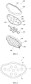
FIG. 1 is an exploded perspective view illustrating a thermotherapy device according to one embodiment of the present disclosure; -
FIG. 2 is a plan view schematically illustrating the thermotherapy device according to the embodiment of the present disclosure; -
FIG. 3 is a plan view illustrating a state in which a front cover, a first supporting plate, and ceramics inFIG. 1 are coupled; -
FIG. 4 is a perspective view illustrating a state before the ceramics inFIG. 3 are inserted; -
FIG. 5 is a cross-sectional view illustrating a state of contact between a heater and the ceramics; -
FIG. 6 is a perspective view illustrating a state in which vibrators are provided in the first supporting plate; -
FIG. 7 is a perspective view illustrating another form of the thermotherapy device according to the embodiment of the present disclosure; and -
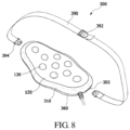
FIG. 8 is a perspective view illustrating still another form of the thermotherapy device according to the embodiment of the present disclosure. - Hereinafter, exemplary embodiments of the present disclosure will be described in detail with reference to the accompanying drawings which allows one of ordinary skill in the art to easily perform the present disclosure. The present disclosure may be implemented in various forms and is not limited to the below-described embodiments. Components not related to the description are omitted in the drawings to clearly describe the present disclosure, and the same reference symbols are used for the same or similar components in the description.
- Hereinafter, a
thermotherapy device 100 according to one embodiment of the present disclosure will be described in more detail with reference to the drawings. - Referring to
FIGS. 1 and 2 , thethermotherapy device 100 according to one embodiment of the present disclosure includes afront cover 110, a first supportingplate 120,ceramics 130, a heater142, a second supportingplate 150, and arear cover 160. - The
front cover 110 may include an exposedpart 112 disposed at a center thereof so that the first supportingplate 120 is outwardly exposed. Here, thefront cover 110 may be disposed at one side of the first supportingplate 120. As an example, with respect toFIG. 1 , thefront cover 110 may be disposed on the first supportingplate 120. - Further, as shown in
FIG. 3 , thefront cover 110 may includehook protrusions 114 in a plurality of locations along an outer circumferential side of a rear surface. Accordingly, thefront cover 110 may be insertion-coupled to the first supportingplate 120. - However, a coupling structure between the
front cover 110 and the first supportingplate 120 is not limited thereto and may have various types. As an example, thefront cover 110 and the first supportingplate 120 may be coupled by bolt coupling, fusion, bonding, or press. - The first supporting
plate 120 may be formed of skin foam. Here, skin foam may have elasticity. Accordingly, the first supportingplate 120 may be formed of a material having elasticity not limited to skin foam. - Accordingly, the
thermotherapy device 100 may reduce noises caused by friction between thefront cover 110, theceramics 130, and the second supportingplate 150 even when vibration is generated by avibrator 170 which will be described below. - Further, since the first supporting
plate 120 is a part configured to directly come into contact with an abdomen of a user, the first supportingplate 120 feels soft because it is made of skin foam. In addition, since the outwardly exposed first supportingplate 120 is formed of skin foam, the first supportingplate 120 has a high quality appearance which looks like leather, and thus satisfaction of the user may be improved. - In addition, a plurality of through
holes 122 may be formed in the first supportingplate 120. Here, the plurality of throughholes 122 may be disposed at locations corresponding to an acupuncture point of an abdomen. In this case, the throughholes 122 may be uniformly or nonuniformly disposed to be distributed throughout the entire first supportingplate 120. - As shown in
FIGS. 4 and 5 , each of the throughholes 122 may include agroove portion 128 therein into which aprotruding portion 132 of each of theceramics 130 is inserted. Each of thethrough holes 122 may be provided to have a diameter the same as that of a lower end portion of each of theceramics 130. Accordingly, theceramics 130 are coupled to the throughholes 122 through a forcible insertion method. - Further, the first supporting
plate 120 may include astep portion 124 along an outer circumferential side thereof. A part of thefront cover 110 on which thehook protrusions 114 are provided may be seated into thestep portion 124. Here, thestep portion 124 may be provided to have a smaller thickness than that of a center of the first supportingplate 120. - In addition, as shown in
FIGS. 1 and3 , the first supportingplate 120 may includehook grooves 126, which correspond to thehook protrusions 114 of thefront cover 110, along the outer circumferential side of the first supportingplate 120. Thestep portion 124 may include thehook grooves 126. - The
ceramics 130 may be formed of a material capable of providing various functions such as far infrared radiation, immunity improvement, electromagnetic wave block, and the like. Further, theceramics 130 may be formed of a material having high conductivity to efficiently transfer heat of theheater 142 to the human body. - Here, each of the
ceramics 130 has no particular limitation in shape, but the end portion may form a globular shape so that theceramics 130 which come into contact with the human body may uniformly apply vibration to the human body when the vibration generated by thevibrator 170 is applied. - In this case, each of the
ceramics 130 may be formed at a predetermined height to protrude to the outside of the first supportingplate 120. Here, the predetermined height may be a height suitable to apply acupressure to the abdomen of the user. That is, each of theceramics 130 may have a cylindrical shape having the predetermined height and an upper end portion which may be convexly formed. - Accordingly, when
ceramics 130 come into contact with the human body, the vibration generated by thevibrator 170 may be more efficiently transferred to the human body. - Further, the plurality of
ceramics 130 may each be insertion-fixed to the plurality of throughholes 122 of the first supportingplate 120. - As shown in
FIGS. 1 and5 , each of theceramics 130 may include the protrudingportion 132 formed to laterally extend along an outer circumferential side of each of theceramics 130. The protrudingportion 132 may be seated into thegroove portion 128 of the first supportingplate 120. Here, a part above the protrudingportion 132 of each of theceramics 130 may have a diameter substantially the same as that of each of the throughholes 122. Accordingly, theceramics 130 may each be insertion-fixed into the throughholes 122 through a forcible insertion method. - Further, since the protruding
portion 132 of each of theceramics 130 is fixed by thegroove portion 128 of the first supportingplate 120, theceramics 130 may not be separated out of the first supportingplate 120 even when thethermotherapy device 100 is vibrated. - In this case, as shown in
FIGS. 3 and 5 , a lower surface of each of theceramics 130 may include a downwardly open hollow 134. That is, each of theceramics 130 may be formed in a dome shape having a predetermined thickness and a hollow center. - Accordingly, when heat is transferred from a heater, since each of the
ceramics 130 transfers the heat along a surface thereof more quickly than a ceramic in which a hollow is filled, thermal efficiency of theceramics 130 may be improved. Further, since theceramics 130 may prevent a loss of a material corresponding to the hollow, manufacturing costs may be reduced. - As described above, since the
front cover 110, the first supportingplate 120, and theceramics 130 are each coupled through an insertion method, a manufacturing process is simplified and time for curing an adhesive is not necessary unlike a conventional thermotherapy device, and thus manufacturing time may be reduced. Accordingly, manufacturing efficiency of thethermotherapy device 100 according to the embodiment of the present disclosure may be improved. - With respect to
FIG. 1 , theheater 142 may be disposed under the plurality ofceramics 130. Theheater 142 is configured to heat the plurality ofceramics 130. Here, theheater 142 is disposed on aheater supporting member 140 or on the second supportingplate 150. Theheater supporting member 140 is configured to support theheater 142, and is not particularly limited to a material thereof. - As described in
FIGS. 1 and5 , theheater 142 is disposed to be in contact with a lower surface of each of the plurality ofceramics 130. That is, theheater 142 is disposed to be in direct contact with a lower surface of the protrudingportion 132 of each of theceramics 130. - Here, the
heater 142 may be formed in an integrally formed linear shape. As an example, theheater 142 may be disposed in a zigzag shape to pass under the lower surface of each of theceramics 130 as a hot wire. That is, as shown inFIG. 1 , theheater 142 may be disposed in a zigzag shape following along a side surface of theheater supporting member 140 while moving from one side of theheater supporting member 140 to another side of theheater supporting member 140. - However, the
heater 142 is not limited to the linear shape and may be formed in a plate shape. In this case, theheater 142 may include an aluminum heater, a non-woven carbon fabric, a cotton mesh heater, and a carbon fiber heater. - Accordingly, the heat generated from the
heater 142 may be efficiently transferred to theceramics 130. Accordingly, the thermal efficiency of the ceramics for a thermal function in thethermotherapy device 100 may be improved. - Further, by providing both acupressure due to vibration of the
ceramics 130 and heat generated by the heat of theheater 142, thethermotherapy device 100 may efficiently improve activation of intestinal movement. - With respect to
FIG. 1 , the second supportingplate 150 is disposed under theheater supporting member 140. Here, theheater supporting member 140 is disposed on an upper surface of the second supportingplate 150, and thevibrator 170 and acircuit 180 may be provided on a lower surface of the second supportingplate 150. - As shown in
FIG. 6 , thevibrator 170 is disposed on a lower surface of the second supportingplate 150. That is, thevibrator 170 may be disposed between the second supportingplate 150 and therear cover 160. - The
vibrator 170 includes amotor 172 and avibration part 174. Here, themotor 172 and thevibration part 174 may be connected by apulley 178 and abelt 179. Accordingly, since thevibration part 174 is eccentrically rotated by rotation of themotor 172, thethermotherapy device 100 may generate vibration. - The
vibration part 174 may be an eccentric vibration part in a semicylindric shape having an eccentric rotary shaft. Here, the rotary shaft of thevibration part 174 may be supported bysupports 176 provided at both sides of thevibration part 174. - Further, two
vibrators 170 may be disposed to be operated perpendicularly to each other. As an example, inFIG. 6 , thevibrator 170 disposed at a left side may be disposed to vibrate in a longitudinal direction of the second supportingplate 150, and thevibrator 170 disposed at a right side may be disposed to vibrate in a width direction of the second supportingplate 150. - In this case, by controlling an order of the longitudinal direction and the width direction of the second supporting
plate 150, various directions of vibration motion may be implemented. - The
circuit 180 may include a power supply configured to supply power to themotor 172, and a controller configured to control an operation of thethermotherapy device 100. Although not shown in the drawings, an operation part which may be operated by the user to operate thethermotherapy device 100 may be provided in thecircuit 180 or provided in the rear cover to be connected to thecircuit 180. Here, the operation part may include a selection part for power on or off, temperature setting, mode setting, and intensity setting. - Further, the
circuit 180 may include a communication part configured to communicate with an external appliance such as a remote controller. In this case, the external appliance may include a selection function of the operation part. - With respect to
FIG. 1 , therear cover 160 may be disposed under the second supportingplate 150. Therear cover 160 may have a shape in which a space, in which thevibrator 170 is provided, is formed between the second supportingplate 150 and therear cover 160. Here, therear cover 160 may be coupled to thefront cover 110 by an insertion method. - Meanwhile, since the
thermotherapy device 100 is operated in a state of being disposed on the abdomen of the user for a certain time, thethermotherapy device 100 may be provided to be holdable by the user. - As shown in
FIG. 7 , in athermotherapy device 200, both sides of each of afront cover 210 and arear cover 260 may includeholes 202 to be held by the user. - Accordingly, massage may be performed in a state in which the
thermotherapy device 200 is held by both hands of the user through theholes 202 and then disposed on a desired portion of the abdomen. Accordingly, the user may easily hold thethermotherapy device 200. - As shown in
FIG. 8 , athermotherapy device 300 may further include a wearingbelt 390 to be worn on a waist of the user. Here, the wearingbelt 390 may include an adjustingpart 392 configured to adjust a length of a belt, and aninsertion part 394 inserted into and fixed to the fixinggroove 302. - To this end, the
thermotherapy device 300 may include fixinggrooves 302, into which the wearingbelt 390 is detachably inserted, in both sides of each of afront cover 310 and arear cover 360. - Meanwhile, to further improve user convenience, the
holes 202 for holding as shown inFIG. 7 , and the wearingbelt 390 as shown inFIG. 8 may be provided together. - As described above, each of the
thermotherapy devices - Further, since the
thermotherapy devices - In addition, since the
thermotherapy devices - In addition, in the
thermotherapy devices - In addition, a user can feel softness at an area which comes into contact with the
thermotherapy devices thermotherapy devices - Although one embodiment of the present disclosure is described above, the present disclosure is not limited to the embodiment shown in the description, and although those skilled in the art may provide other embodiments due to addition, change, or removal of the components within the scope of the present disclosure, the above embodiments are also included in the scope of the present disclosure as claimed.
Claims (6)
- A thermotherapy device (100) comprising:a first supporting plate (120) having a plurality of through holes (122) formed therein and formed of skin foam;a front cover (110) coupled to the first supporting plate (120) with one side of the first supporting plate exposed;a plurality of ceramics (130) each insertion-fixed to the plurality of through holes (122), and each configured to protrude to the outside of the first supporting plate to a predetermined height;a heater (142) disposed on one sides of the plurality of ceramics (130) and configured to heat the plurality of ceramics (130);a heater supporting member (140) configured to support the heater;a second supporting plate (150) disposed on one side of the heater and including a vibrator (170); anda rear cover (160) disposed on one side of the second supporting plate (150) and coupled to the front cover (110),characterized in that the plurality of ceramics are press fit to the plurality of through holes;wherein the heater is arranged to simultaneously support a lower surface of the ceramics and a lower surface of the first supporting plate,wherein an upper surface of the second supporting plate is arranged to support a lower surface of the heater supporting member,wherein the vibrator is provided on a lower surface of the second supporting plate.
- The thermotherapy device of claim 1, wherein the heater (142) is disposed to be in contact with lower surfaces of the plurality of ceramics (130), is formed in a plate shape or a linear shape, and includes one among a hot wire, an aluminum heater, a non-woven carbon fabric, a cotton mesh heater, and a carbon fiber heater.
- The thermotherapy device of claim 1, wherein each of the plurality of ceramics (130) includes a downwardly open hollow.
- The thermotherapy device of claim 1, wherein:the ceramics (130) include a protruding portion (132) formed to extend toward a side surface along an outer circumferential side;the first supporting plate (120) includes a groove portion (128) provided so that the protruding portion is inserted into the through hole.
- The thermotherapy device of claim 1, wherein each of the front cover and the rear cover includes holes in both sides thereof to be held by a user.
- The thermotherapy device of claim 1, further comprising a wearing belt (390) to be worn on a waist of the user,
wherein the front cover and the rear cover include fixing grooves so that the wearing belt is detachably inserted into both sides thereof.
Applications Claiming Priority (2)
| Application Number | Priority Date | Filing Date | Title |
|---|---|---|---|
| KR1020180023967A KR102000700B1 (en) | 2018-02-27 | 2018-02-27 | Thermo-therapeutic apparatus |
| PCT/KR2019/000992 WO2019168268A1 (en) | 2018-02-27 | 2019-01-24 | Thermotherapy device |
Publications (3)
| Publication Number | Publication Date |
|---|---|
| EP3760171A1 EP3760171A1 (en) | 2021-01-06 |
| EP3760171A4 EP3760171A4 (en) | 2021-12-01 |
| EP3760171B1 true EP3760171B1 (en) | 2024-10-23 |
Family
ID=67512831
Family Applications (1)
| Application Number | Title | Priority Date | Filing Date |
|---|---|---|---|
| EP19760472.1A Active EP3760171B1 (en) | 2018-02-27 | 2019-01-24 | Thermotherapy device |
Country Status (14)
| Country | Link |
|---|---|
| US (1) | US12005017B2 (en) |
| EP (1) | EP3760171B1 (en) |
| JP (1) | JP7016424B2 (en) |
| KR (1) | KR102000700B1 (en) |
| CN (1) | CN110192971B (en) |
| BR (1) | BR112020016924A2 (en) |
| CL (1) | CL2020002153A1 (en) |
| ES (1) | ES2993357T3 (en) |
| MX (1) | MX2020008928A (en) |
| MY (1) | MY205204A (en) |
| PE (1) | PE20201331A1 (en) |
| PH (1) | PH12020551326A1 (en) |
| RU (1) | RU2752807C1 (en) |
| WO (1) | WO2019168268A1 (en) |
Families Citing this family (15)
| Publication number | Priority date | Publication date | Assignee | Title |
|---|---|---|---|---|
| USD925668S1 (en) * | 2018-07-20 | 2021-07-20 | Coulter Ventures, Llc. | Weight vest plate |
| USD925667S1 (en) * | 2018-07-20 | 2021-07-20 | Coulter Ventures, Llc. | Weight vest plate |
| US11134785B1 (en) * | 2019-02-26 | 2021-10-05 | Janice Smatt | Vibrating foot rest |
| CN111067698B (en) * | 2019-12-31 | 2022-02-22 | 青岛温可微电子科技有限公司 | Adhesive heating device and manufacturing method thereof |
| US20220193440A1 (en) * | 2020-03-30 | 2022-06-23 | Dynamic Medical Technologies, Inc. | Light therapy device for treatment of the vagina and vulva |
| US11357698B2 (en) * | 2020-11-25 | 2022-06-14 | Mmj Labs, Llc | System, method and apparatus for pain control and healing |
| KR102535707B1 (en) * | 2020-11-26 | 2023-05-23 | 주식회사 세라젬 | Thermo-therapeutic apparutus |
| KR102464239B1 (en) * | 2021-12-14 | 2022-11-04 | 함창호 | belly band |
| JP1766647S (en) * | 2022-02-08 | 2024-03-27 | Anti-wrinkle device | |
| KR102886834B1 (en) * | 2023-03-17 | 2025-11-21 | 주식회사 엘에이치생활건강 | Y-zone massage device |
| US20240358575A1 (en) * | 2023-04-28 | 2024-10-31 | Franklin R Lacy | Improved system for gastrointestinal health |
| KR20250054295A (en) * | 2023-10-13 | 2025-04-23 | 주식회사 세라젬 | Abdominal heating apparatus comprising heating ceramics |
| US20250281345A1 (en) * | 2024-03-10 | 2025-09-11 | Angie Wong | Therapeutic brace utilizing active release technology |
| KR102897232B1 (en) | 2024-06-04 | 2025-12-11 | 신대원 | Antibacterial and antiviral composite sintering material using copper and silver and manufacturing method thereof |
| USD1133063S1 (en) | 2024-06-17 | 2026-07-07 | Coulter Ventures, Llc. | Weight plate |
Family Cites Families (50)
| Publication number | Priority date | Publication date | Assignee | Title |
|---|---|---|---|---|
| US4210134A (en) * | 1978-03-09 | 1980-07-01 | Kabushikigaisha Omco | Pillow for manual therapeutics |
| US5336159A (en) * | 1992-08-25 | 1994-08-09 | Cheng Tzu Keng | Infrared massager |
| DE4406063A1 (en) * | 1994-02-24 | 1995-08-31 | Prodomo Sa | Insole |
| US20020068886A1 (en) * | 2000-12-04 | 2002-06-06 | Pin-Hung Lin | Detachable, hot-packing and massaging strap |
| CN1481265A (en) * | 2001-10-18 | 2004-03-10 | 株式会社美人娜拉 | Personal thermotherapy device with massage function |
| US6511446B1 (en) * | 2001-11-16 | 2003-01-28 | Chia-Hsiung Wu | Message bead with heat application effect |
| JP3627107B2 (en) * | 2001-11-30 | 2005-03-09 | 小原 憲 | Warmth |
| JP3746228B2 (en) * | 2001-12-04 | 2006-02-15 | 株式会社岩田良 | Foot pressure device |
| JP2003204982A (en) * | 2002-01-09 | 2003-07-22 | Byeong Gon Kim | Abdominal heat vibration belt |
| JP3091042U (en) | 2002-06-27 | 2003-01-17 | 家▲めい▼ 胡 | Massage hammer with hot air vibration function |
| JP2004073643A (en) | 2002-08-21 | 2004-03-11 | Teranishi Denki Seisakusho:Kk | Massage machine |
| KR200318298Y1 (en) * | 2003-04-12 | 2003-06-28 | 김기원 | Complex stimulus prove for fatness improvement |
| US20050043655A1 (en) * | 2003-08-18 | 2005-02-24 | David Schenck | Back support device |
| US20050059909A1 (en) * | 2003-09-11 | 2005-03-17 | Burgess Dorothy M. | Cervical heat and vibration massage apparatus |
| KR200353662Y1 (en) * | 2003-11-19 | 2004-06-22 | 윤동업 | Physical therapy equipment for abdomen |
| CN2684862Y (en) * | 2004-01-09 | 2005-03-16 | 武汉楚天光电子有限公司 | Vibrating thermotherapeutical device |
| CN2724665Y (en) * | 2004-01-30 | 2005-09-14 | 郑哲雄 | Hot therapeutic apparatus |
| KR200353602Y1 (en) * | 2004-03-15 | 2004-06-22 | 박종호 | sterilization system of hand phone using ozone gas |
| KR200353619Y1 (en) * | 2004-03-18 | 2004-06-18 | 조지원 | thermo therapy mat |
| US7322946B2 (en) * | 2004-03-19 | 2008-01-29 | Fka Distributing Co. | Massage apparatus |
| KR20050094935A (en) * | 2004-03-23 | 2005-09-29 | (주)호성실업 | Low frequency vibrating generate heat stimulation apparatus |
| JP2005296378A (en) * | 2004-04-13 | 2005-10-27 | Takashi Yanai | Foot warmer with massage function and foot warmer storing bag |
| CN1689537A (en) * | 2004-04-22 | 2005-11-02 | 北京碧健医疗器械有限公司 | Portable heat treatment apparatus |
| US20060129072A1 (en) * | 2004-12-10 | 2006-06-15 | Shin Thomas J | Far infra-red ray and anion emitting thermal rotary massage device for decreasing the fat in the abdominal region of a human body |
| AU2005320358A1 (en) * | 2005-07-28 | 2007-02-15 | Os Health Care Co., Ltd | Massage belt |
| JP2007151790A (en) | 2005-12-05 | 2007-06-21 | Nippon Riko Igaku Kenkyusho:Kk | Moxibustion device |
| KR100772033B1 (en) * | 2006-11-17 | 2007-10-31 | (주) 쉬즈텍 | Hand Relaxation Mechanism |
| JP2008178523A (en) * | 2007-01-24 | 2008-08-07 | Marutaka Techno:Kk | Ultrashortwave therapy apparatus |
| KR101031284B1 (en) * | 2008-02-25 | 2011-04-29 | 양원동 | Functional neck band |
| US20100161014A1 (en) * | 2008-12-23 | 2010-06-24 | Lynch Joseph M | Thermal treatment device |
| KR100920239B1 (en) * | 2009-07-06 | 2009-10-05 | 손기준 | Pneumatic massage belt |
| CN201460129U (en) * | 2009-07-09 | 2010-05-12 | 马韬 | Health-care massage floor |
| KR101205555B1 (en) * | 2009-11-09 | 2012-11-28 | 주식회사 세라젬 | Hyperthermo-radiation Projector for the Hyperthermo-therapeutic Apparatus |
| RU2013138682A (en) * | 2011-01-25 | 2015-03-10 | Яффа Голан | MASSAGE SHOES |
| JP3169233U (en) | 2011-05-10 | 2011-07-21 | 能保康企業股▲ふん▼有限公司 | Infrared Quasa Electric Furnace for Health |
| KR101312655B1 (en) * | 2011-09-21 | 2013-09-27 | 김경훈 | Foot massage |
| CN202537923U (en) * | 2012-01-18 | 2012-11-21 | 韩国建 | Self-service acupoint pressure device |
| CN104095741B (en) * | 2013-04-09 | 2017-09-12 | 喜来健株式会社 | A kind of thermotherapeutic apparatus |
| TWM471879U (en) * | 2013-08-08 | 2014-02-11 | Mei Chi Na Hsinyen Co Ltd | Cosmetic device with magnetic attraction structure and replaceable cosmetic components |
| CN103735125A (en) * | 2014-01-02 | 2014-04-23 | 苏州博元纺织实业有限公司 | Multifunctional floor mat |
| KR101518670B1 (en) * | 2014-05-07 | 2015-05-11 | 주식회사 세라젬 | Curer |
| CN105249600A (en) * | 2015-10-22 | 2016-01-20 | 孔远萍 | Massage shoe |
| CN105534692B (en) * | 2016-02-05 | 2017-09-15 | 黄文佳 | A kind of intelligent foot massage physiotherapy equipment |
| KR101766338B1 (en) | 2016-06-08 | 2017-08-08 | 타임마스터(주) | Abdomen hyperthermia wave laser pads for incontinence treatment and prevention and inguinal lymph circulation |
| US20190167506A1 (en) * | 2016-06-27 | 2019-06-06 | Cse Co., Ltd | Neck traction apparatus having traction assisting device |
| CN106618854A (en) * | 2016-11-11 | 2017-05-10 | 广东商旅宝健康科技有限公司 | Multifunctional healthcare eye patch |
| KR20180065380A (en) * | 2016-12-07 | 2018-06-18 | 주식회사 카멜 | hot and cold heat treatment equipment using thermoelectric element |
| CN107308527A (en) * | 2017-05-08 | 2017-11-03 | 管桂芳 | A kind of Psychosomatic disease therapeutic device |
| CN107411945A (en) * | 2017-05-23 | 2017-12-01 | 艾桂荣 | A kind of shell type back massager |
| US20210015701A1 (en) * | 2019-07-16 | 2021-01-21 | SMS Products LLC | Systems and methods for providing a menstrual cramp relief belt |
-
2018
- 2018-02-27 KR KR1020180023967A patent/KR102000700B1/en active Active
-
2019
- 2019-01-24 MX MX2020008928A patent/MX2020008928A/en unknown
- 2019-01-24 MY MYPI2020003962A patent/MY205204A/en unknown
- 2019-01-24 WO PCT/KR2019/000992 patent/WO2019168268A1/en not_active Ceased
- 2019-01-24 ES ES19760472T patent/ES2993357T3/en active Active
- 2019-01-24 EP EP19760472.1A patent/EP3760171B1/en active Active
- 2019-01-24 RU RU2020128283A patent/RU2752807C1/en active
- 2019-01-24 BR BR112020016924-2A patent/BR112020016924A2/en not_active Application Discontinuation
- 2019-01-24 PE PE2020001267A patent/PE20201331A1/en unknown
- 2019-01-24 JP JP2020544928A patent/JP7016424B2/en active Active
- 2019-01-29 CN CN201910086531.XA patent/CN110192971B/en active Active
- 2019-02-20 US US16/280,114 patent/US12005017B2/en active Active
-
2020
- 2020-08-20 CL CL2020002153A patent/CL2020002153A1/en unknown
- 2020-08-25 PH PH12020551326A patent/PH12020551326A1/en unknown
Also Published As
| Publication number | Publication date |
|---|---|
| JP2021514741A (en) | 2021-06-17 |
| PH12020551326A1 (en) | 2021-09-01 |
| CN110192971B (en) | 2022-10-14 |
| JP7016424B2 (en) | 2022-02-04 |
| CN110192971A (en) | 2019-09-03 |
| US12005017B2 (en) | 2024-06-11 |
| KR102000700B1 (en) | 2019-07-17 |
| CL2020002153A1 (en) | 2021-01-22 |
| PE20201331A1 (en) | 2020-11-25 |
| MY205204A (en) | 2024-10-07 |
| RU2752807C1 (en) | 2021-08-06 |
| ES2993357T3 (en) | 2024-12-27 |
| US20190262207A1 (en) | 2019-08-29 |
| EP3760171A4 (en) | 2021-12-01 |
| WO2019168268A1 (en) | 2019-09-06 |
| EP3760171A1 (en) | 2021-01-06 |
| BR112020016924A2 (en) | 2020-12-15 |
| MX2020008928A (en) | 2020-10-01 |
Similar Documents
| Publication | Publication Date | Title |
|---|---|---|
| US12005017B2 (en) | Thermo-therapeutic apparatus | |
| CN109419618B (en) | Massager with vibrator | |
| KR101018728B1 (en) | Chair massage equipment | |
| KR101030572B1 (en) | Massage device for breast surgery | |
| KR200353662Y1 (en) | Physical therapy equipment for abdomen | |
| KR20040073928A (en) | Mask for face massage | |
| HK40034694A (en) | Thermotherapy device | |
| KR20180045546A (en) | Masssager equipped with an extension module | |
| JP2016140658A (en) | Chest massager | |
| KR102034473B1 (en) | Massage device | |
| KR20200087386A (en) | Massage device for prostate | |
| KR20090011069U (en) | Limb compression air massager | |
| KR200298371Y1 (en) | Structure for massage a bed have doubleness the rotation whirlpool type of vibration motor | |
| KR100746045B1 (en) | Physical therapy apparatus | |
| KR100592519B1 (en) | Thermal therapy machine containing far infrared emitter | |
| KR19990004942U (en) | Infrared thermotherapy machine with vibration function | |
| CN216061252U (en) | Massage device | |
| CN206063398U (en) | Prostate warms massage cushion | |
| KR101756302B1 (en) | Breast massage apparatus and control method thereof | |
| KR200217859Y1 (en) | Foot massage machine | |
| KR200338965Y1 (en) | A massage bend | |
| KR200318298Y1 (en) | Complex stimulus prove for fatness improvement | |
| KR200368070Y1 (en) | medical support appliances | |
| KR19990041336U (en) | Vibrating Ocher Massager | |
| KR20010109255A (en) | Apparatus for Massaging Womans Breast |
Legal Events
| Date | Code | Title | Description |
|---|---|---|---|
| STAA | Information on the status of an ep patent application or granted ep patent |
Free format text: STATUS: THE INTERNATIONAL PUBLICATION HAS BEEN MADE |
|
| PUAI | Public reference made under article 153(3) epc to a published international application that has entered the european phase |
Free format text: ORIGINAL CODE: 0009012 |
|
| STAA | Information on the status of an ep patent application or granted ep patent |
Free format text: STATUS: REQUEST FOR EXAMINATION WAS MADE |
|
| 17P | Request for examination filed |
Effective date: 20200818 |
|
| AK | Designated contracting states |
Kind code of ref document: A1 Designated state(s): AL AT BE BG CH CY CZ DE DK EE ES FI FR GB GR HR HU IE IS IT LI LT LU LV MC MK MT NL NO PL PT RO RS SE SI SK SM TR |
|
| AX | Request for extension of the european patent |
Extension state: BA ME |
|
| REG | Reference to a national code |
Ref country code: HK Ref legal event code: DE Ref document number: 40034694 Country of ref document: HK |
|
| DAX | Request for extension of the european patent (deleted) | ||
| RAV | Requested validation state of the european patent: fee paid |
Extension state: MD Effective date: 20200818 |
|
| A4 | Supplementary search report drawn up and despatched |
Effective date: 20211103 |
|
| RIC1 | Information provided on ipc code assigned before grant |
Ipc: A61F 7/02 20060101ALI20211027BHEP Ipc: A61H 23/02 20060101ALI20211027BHEP Ipc: A61H 39/04 20060101ALI20211027BHEP Ipc: A61H 39/00 20060101ALI20211027BHEP Ipc: A61F 7/00 20060101AFI20211027BHEP |
|
| STAA | Information on the status of an ep patent application or granted ep patent |
Free format text: STATUS: EXAMINATION IS IN PROGRESS |
|
| 17Q | First examination report despatched |
Effective date: 20240104 |
|
| GRAP | Despatch of communication of intention to grant a patent |
Free format text: ORIGINAL CODE: EPIDOSNIGR1 |
|
| STAA | Information on the status of an ep patent application or granted ep patent |
Free format text: STATUS: GRANT OF PATENT IS INTENDED |
|
| INTG | Intention to grant announced |
Effective date: 20240528 |
|
| GRAS | Grant fee paid |
Free format text: ORIGINAL CODE: EPIDOSNIGR3 |
|
| GRAA | (expected) grant |
Free format text: ORIGINAL CODE: 0009210 |
|
| STAA | Information on the status of an ep patent application or granted ep patent |
Free format text: STATUS: THE PATENT HAS BEEN GRANTED |
|
| AK | Designated contracting states |
Kind code of ref document: B1 Designated state(s): AL AT BE BG CH CY CZ DE DK EE ES FI FR GB GR HR HU IE IS IT LI LT LU LV MC MK MT NL NO PL PT RO RS SE SI SK SM TR |
|
| REG | Reference to a national code |
Ref country code: GB Ref legal event code: FG4D |
|
| REG | Reference to a national code |
Ref country code: CH Ref legal event code: EP |
|
| REG | Reference to a national code |
Ref country code: DE Ref legal event code: R096 Ref document number: 602019060806 Country of ref document: DE |
|
| REG | Reference to a national code |
Ref country code: IE Ref legal event code: FG4D |
|
| REG | Reference to a national code |
Ref country code: ES Ref legal event code: FG2A Ref document number: 2993357 Country of ref document: ES Kind code of ref document: T3 Effective date: 20241227 |
|
| REG | Reference to a national code |
Ref country code: LT Ref legal event code: MG9D |
|
| REG | Reference to a national code |
Ref country code: NL Ref legal event code: MP Effective date: 20241023 |
|
| REG | Reference to a national code |
Ref country code: AT Ref legal event code: MK05 Ref document number: 1734221 Country of ref document: AT Kind code of ref document: T Effective date: 20241023 |
|
| PG25 | Lapsed in a contracting state [announced via postgrant information from national office to epo] |
Ref country code: NL Free format text: LAPSE BECAUSE OF FAILURE TO SUBMIT A TRANSLATION OF THE DESCRIPTION OR TO PAY THE FEE WITHIN THE PRESCRIBED TIME-LIMIT Effective date: 20241023 |
|
| PG25 | Lapsed in a contracting state [announced via postgrant information from national office to epo] |
Ref country code: NL Free format text: LAPSE BECAUSE OF FAILURE TO SUBMIT A TRANSLATION OF THE DESCRIPTION OR TO PAY THE FEE WITHIN THE PRESCRIBED TIME-LIMIT Effective date: 20241023 |
|
| PG25 | Lapsed in a contracting state [announced via postgrant information from national office to epo] |
Ref country code: HR Free format text: LAPSE BECAUSE OF FAILURE TO SUBMIT A TRANSLATION OF THE DESCRIPTION OR TO PAY THE FEE WITHIN THE PRESCRIBED TIME-LIMIT Effective date: 20241023 Ref country code: IS Free format text: LAPSE BECAUSE OF FAILURE TO SUBMIT A TRANSLATION OF THE DESCRIPTION OR TO PAY THE FEE WITHIN THE PRESCRIBED TIME-LIMIT Effective date: 20250223 Ref country code: PT Free format text: LAPSE BECAUSE OF FAILURE TO SUBMIT A TRANSLATION OF THE DESCRIPTION OR TO PAY THE FEE WITHIN THE PRESCRIBED TIME-LIMIT Effective date: 20250224 |
|
| PG25 | Lapsed in a contracting state [announced via postgrant information from national office to epo] |
Ref country code: FI Free format text: LAPSE BECAUSE OF FAILURE TO SUBMIT A TRANSLATION OF THE DESCRIPTION OR TO PAY THE FEE WITHIN THE PRESCRIBED TIME-LIMIT Effective date: 20241023 |
|
| PG25 | Lapsed in a contracting state [announced via postgrant information from national office to epo] |
Ref country code: BG Free format text: LAPSE BECAUSE OF FAILURE TO SUBMIT A TRANSLATION OF THE DESCRIPTION OR TO PAY THE FEE WITHIN THE PRESCRIBED TIME-LIMIT Effective date: 20241023 |
|
| PG25 | Lapsed in a contracting state [announced via postgrant information from national office to epo] |
Ref country code: NO Free format text: LAPSE BECAUSE OF FAILURE TO SUBMIT A TRANSLATION OF THE DESCRIPTION OR TO PAY THE FEE WITHIN THE PRESCRIBED TIME-LIMIT Effective date: 20250123 |
|
| PG25 | Lapsed in a contracting state [announced via postgrant information from national office to epo] |
Ref country code: LV Free format text: LAPSE BECAUSE OF FAILURE TO SUBMIT A TRANSLATION OF THE DESCRIPTION OR TO PAY THE FEE WITHIN THE PRESCRIBED TIME-LIMIT Effective date: 20241023 Ref country code: AT Free format text: LAPSE BECAUSE OF FAILURE TO SUBMIT A TRANSLATION OF THE DESCRIPTION OR TO PAY THE FEE WITHIN THE PRESCRIBED TIME-LIMIT Effective date: 20241023 Ref country code: GR Free format text: LAPSE BECAUSE OF FAILURE TO SUBMIT A TRANSLATION OF THE DESCRIPTION OR TO PAY THE FEE WITHIN THE PRESCRIBED TIME-LIMIT Effective date: 20250124 |
|
| PG25 | Lapsed in a contracting state [announced via postgrant information from national office to epo] |
Ref country code: PL Free format text: LAPSE BECAUSE OF FAILURE TO SUBMIT A TRANSLATION OF THE DESCRIPTION OR TO PAY THE FEE WITHIN THE PRESCRIBED TIME-LIMIT Effective date: 20241023 |
|
| PG25 | Lapsed in a contracting state [announced via postgrant information from national office to epo] |
Ref country code: RS Free format text: LAPSE BECAUSE OF FAILURE TO SUBMIT A TRANSLATION OF THE DESCRIPTION OR TO PAY THE FEE WITHIN THE PRESCRIBED TIME-LIMIT Effective date: 20250123 |
|
| PG25 | Lapsed in a contracting state [announced via postgrant information from national office to epo] |
Ref country code: SM Free format text: LAPSE BECAUSE OF FAILURE TO SUBMIT A TRANSLATION OF THE DESCRIPTION OR TO PAY THE FEE WITHIN THE PRESCRIBED TIME-LIMIT Effective date: 20241023 |
|
| PG25 | Lapsed in a contracting state [announced via postgrant information from national office to epo] |
Ref country code: DK Free format text: LAPSE BECAUSE OF FAILURE TO SUBMIT A TRANSLATION OF THE DESCRIPTION OR TO PAY THE FEE WITHIN THE PRESCRIBED TIME-LIMIT Effective date: 20241023 |
|
| VS25 | Lapsed in a validation state [announced via postgrant information from nat. office to epo] |
Ref country code: MD Free format text: LAPSE BECAUSE OF FAILURE TO SUBMIT A TRANSLATION OF THE DESCRIPTION OR TO PAY THE FEE WITHIN THE PRESCRIBED TIME-LIMIT Effective date: 20241023 |
|
| PG25 | Lapsed in a contracting state [announced via postgrant information from national office to epo] |
Ref country code: EE Free format text: LAPSE BECAUSE OF FAILURE TO SUBMIT A TRANSLATION OF THE DESCRIPTION OR TO PAY THE FEE WITHIN THE PRESCRIBED TIME-LIMIT Effective date: 20241023 |
|
| PG25 | Lapsed in a contracting state [announced via postgrant information from national office to epo] |
Ref country code: RO Free format text: LAPSE BECAUSE OF FAILURE TO SUBMIT A TRANSLATION OF THE DESCRIPTION OR TO PAY THE FEE WITHIN THE PRESCRIBED TIME-LIMIT Effective date: 20241023 |
|
| REG | Reference to a national code |
Ref country code: DE Ref legal event code: R097 Ref document number: 602019060806 Country of ref document: DE |
|
| PG25 | Lapsed in a contracting state [announced via postgrant information from national office to epo] |
Ref country code: SK Free format text: LAPSE BECAUSE OF FAILURE TO SUBMIT A TRANSLATION OF THE DESCRIPTION OR TO PAY THE FEE WITHIN THE PRESCRIBED TIME-LIMIT Effective date: 20241023 |
|
| PG25 | Lapsed in a contracting state [announced via postgrant information from national office to epo] |
Ref country code: CZ Free format text: LAPSE BECAUSE OF FAILURE TO SUBMIT A TRANSLATION OF THE DESCRIPTION OR TO PAY THE FEE WITHIN THE PRESCRIBED TIME-LIMIT Effective date: 20241023 |
|
| PG25 | Lapsed in a contracting state [announced via postgrant information from national office to epo] |
Ref country code: IT Free format text: LAPSE BECAUSE OF FAILURE TO SUBMIT A TRANSLATION OF THE DESCRIPTION OR TO PAY THE FEE WITHIN THE PRESCRIBED TIME-LIMIT Effective date: 20241023 |
|
| PLBE | No opposition filed within time limit |
Free format text: ORIGINAL CODE: 0009261 |
|
| REG | Reference to a national code |
Ref country code: CH Ref legal event code: PL |
|
| STAA | Information on the status of an ep patent application or granted ep patent |
Free format text: STATUS: NO OPPOSITION FILED WITHIN TIME LIMIT |
|
| PG25 | Lapsed in a contracting state [announced via postgrant information from national office to epo] |
Ref country code: SE Free format text: LAPSE BECAUSE OF FAILURE TO SUBMIT A TRANSLATION OF THE DESCRIPTION OR TO PAY THE FEE WITHIN THE PRESCRIBED TIME-LIMIT Effective date: 20241023 |
|
| PG25 | Lapsed in a contracting state [announced via postgrant information from national office to epo] |
Ref country code: LU Free format text: LAPSE BECAUSE OF NON-PAYMENT OF DUE FEES Effective date: 20250124 Ref country code: MC Free format text: LAPSE BECAUSE OF FAILURE TO SUBMIT A TRANSLATION OF THE DESCRIPTION OR TO PAY THE FEE WITHIN THE PRESCRIBED TIME-LIMIT Effective date: 20241023 |
|
| 26N | No opposition filed |
Effective date: 20250724 |
|
| PG25 | Lapsed in a contracting state [announced via postgrant information from national office to epo] |
Ref country code: BE Free format text: LAPSE BECAUSE OF NON-PAYMENT OF DUE FEES Effective date: 20250131 |
|
| PG25 | Lapsed in a contracting state [announced via postgrant information from national office to epo] |
Ref country code: FR Free format text: LAPSE BECAUSE OF NON-PAYMENT OF DUE FEES Effective date: 20250131 |
|
| PG25 | Lapsed in a contracting state [announced via postgrant information from national office to epo] |
Ref country code: CH Free format text: LAPSE BECAUSE OF NON-PAYMENT OF DUE FEES Effective date: 20250131 |
|
| REG | Reference to a national code |
Ref country code: BE Ref legal event code: MM Effective date: 20250131 |
|
| PG25 | Lapsed in a contracting state [announced via postgrant information from national office to epo] |
Ref country code: IE Free format text: LAPSE BECAUSE OF NON-PAYMENT OF DUE FEES Effective date: 20250124 |
|
| PGFP | Annual fee paid to national office [announced via postgrant information from national office to epo] |
Ref country code: GB Payment date: 20260122 Year of fee payment: 8 |
|
| PGFP | Annual fee paid to national office [announced via postgrant information from national office to epo] |
Ref country code: ES Payment date: 20260217 Year of fee payment: 8 |
|
| PGFP | Annual fee paid to national office [announced via postgrant information from national office to epo] |
Ref country code: DE Payment date: 20260120 Year of fee payment: 8 |
|
| PG25 | Lapsed in a contracting state [announced via postgrant information from national office to epo] |
Ref country code: CY Free format text: LAPSE BECAUSE OF FAILURE TO SUBMIT A TRANSLATION OF THE DESCRIPTION OR TO PAY THE FEE WITHIN THE PRESCRIBED TIME-LIMIT Effective date: 20241023 |
|
| PG25 | Lapsed in a contracting state [announced via postgrant information from national office to epo] |
Ref country code: TR Free format text: LAPSE BECAUSE OF FAILURE TO SUBMIT A TRANSLATION OF THE DESCRIPTION OR TO PAY THE FEE WITHIN THE PRESCRIBED TIME-LIMIT Effective date: 20241023 |
|
| PG25 | Lapsed in a contracting state [announced via postgrant information from national office to epo] |
Ref country code: LT Free format text: LAPSE BECAUSE OF FAILURE TO SUBMIT A TRANSLATION OF THE DESCRIPTION OR TO PAY THE FEE WITHIN THE PRESCRIBED TIME-LIMIT Effective date: 20241023 |