EP3760128A1 - Collimator, radiation detection device, and radiation inspection device - Google Patents
Collimator, radiation detection device, and radiation inspection device Download PDFInfo
- Publication number
- EP3760128A1 EP3760128A1 EP18908188.8A EP18908188A EP3760128A1 EP 3760128 A1 EP3760128 A1 EP 3760128A1 EP 18908188 A EP18908188 A EP 18908188A EP 3760128 A1 EP3760128 A1 EP 3760128A1
- Authority
- EP
- European Patent Office
- Prior art keywords
- radiation
- ray
- collimator
- section
- transmission section
- Prior art date
- Legal status (The legal status is an assumption and is not a legal conclusion. Google has not performed a legal analysis and makes no representation as to the accuracy of the status listed.)
- Granted
Links
Images



Classifications
-
- A—HUMAN NECESSITIES
- A61—MEDICAL OR VETERINARY SCIENCE; HYGIENE
- A61B—DIAGNOSIS; SURGERY; IDENTIFICATION
- A61B6/00—Apparatus or devices for radiation diagnosis; Apparatus or devices for radiation diagnosis combined with radiation therapy equipment
- A61B6/52—Devices using data or image processing specially adapted for radiation diagnosis
- A61B6/5258—Devices using data or image processing specially adapted for radiation diagnosis involving detection or reduction of artifacts or noise
- A61B6/5282—Devices using data or image processing specially adapted for radiation diagnosis involving detection or reduction of artifacts or noise due to scatter
-
- A—HUMAN NECESSITIES
- A61—MEDICAL OR VETERINARY SCIENCE; HYGIENE
- A61B—DIAGNOSIS; SURGERY; IDENTIFICATION
- A61B6/00—Apparatus or devices for radiation diagnosis; Apparatus or devices for radiation diagnosis combined with radiation therapy equipment
- A61B6/02—Arrangements for diagnosis sequentially in different planes; Stereoscopic radiation diagnosis
- A61B6/03—Computed tomography [CT]
-
- A—HUMAN NECESSITIES
- A61—MEDICAL OR VETERINARY SCIENCE; HYGIENE
- A61B—DIAGNOSIS; SURGERY; IDENTIFICATION
- A61B6/00—Apparatus or devices for radiation diagnosis; Apparatus or devices for radiation diagnosis combined with radiation therapy equipment
- A61B6/02—Arrangements for diagnosis sequentially in different planes; Stereoscopic radiation diagnosis
- A61B6/03—Computed tomography [CT]
- A61B6/032—Transmission computed tomography [CT]
-
- A—HUMAN NECESSITIES
- A61—MEDICAL OR VETERINARY SCIENCE; HYGIENE
- A61B—DIAGNOSIS; SURGERY; IDENTIFICATION
- A61B6/00—Apparatus or devices for radiation diagnosis; Apparatus or devices for radiation diagnosis combined with radiation therapy equipment
- A61B6/10—Safety means specially adapted therefor
- A61B6/107—Protection against radiation, e.g. shielding
-
- A—HUMAN NECESSITIES
- A61—MEDICAL OR VETERINARY SCIENCE; HYGIENE
- A61B—DIAGNOSIS; SURGERY; IDENTIFICATION
- A61B6/00—Apparatus or devices for radiation diagnosis; Apparatus or devices for radiation diagnosis combined with radiation therapy equipment
- A61B6/42—Arrangements for detecting radiation specially adapted for radiation diagnosis
- A61B6/4291—Arrangements for detecting radiation specially adapted for radiation diagnosis the detector being combined with a grid or grating
-
- G—PHYSICS
- G21—NUCLEAR PHYSICS; NUCLEAR ENGINEERING
- G21K—HANDLING OF PARTICLES OR IONISING RADIATION NOT OTHERWISE PROVIDED FOR; IRRADIATION DEVICES; GAMMA RAY OR X-RAY MICROSCOPES
- G21K1/00—Arrangements for handling particles or ionising radiation, e.g. focusing or moderating
- G21K1/02—Arrangements for handling particles or ionising radiation, e.g. focusing or moderating using diaphragms, collimators
-
- G—PHYSICS
- G21—NUCLEAR PHYSICS; NUCLEAR ENGINEERING
- G21K—HANDLING OF PARTICLES OR IONISING RADIATION NOT OTHERWISE PROVIDED FOR; IRRADIATION DEVICES; GAMMA RAY OR X-RAY MICROSCOPES
- G21K1/00—Arrangements for handling particles or ionising radiation, e.g. focusing or moderating
- G21K1/02—Arrangements for handling particles or ionising radiation, e.g. focusing or moderating using diaphragms, collimators
- G21K1/025—Arrangements for handling particles or ionising radiation, e.g. focusing or moderating using diaphragms, collimators using multiple collimators, e.g. Bucky screens; other devices for eliminating undesired or dispersed radiation
-
- A—HUMAN NECESSITIES
- A61—MEDICAL OR VETERINARY SCIENCE; HYGIENE
- A61B—DIAGNOSIS; SURGERY; IDENTIFICATION
- A61B6/00—Apparatus or devices for radiation diagnosis; Apparatus or devices for radiation diagnosis combined with radiation therapy equipment
- A61B6/06—Diaphragms
Definitions
- the present invention relates to a collimator, radiation detection device, and radiation inspection device.
- Radiation inspection devices that perform nondestructive testing, such as, for example, X-ray computed tomography (CT) devices, irradiate a subject with radiation and generate a CT image based on the radiation transmitted through the subject.
- CT computed tomography
- This kind of radiation inspection device is equipped with a radiation emitting device and a radiation detection device.
- the radiation irradiated onto the subject is partially scattered inside the subject.
- the radiation detection device detects scattered radiation, detection accuracy deteriorates.
- the radiation detection device is provided with a collimator.
- Collimators are conventionally provided with a plurality of through holes that transmit radiation.
- radiation passes through these through holes, radiation that enters a through hole at an angle equal to or greater than a predetermined angle relative to a central axis of the through hole collides with the sidewall of the through hole. Since scattered radiation that degrades detection accuracy is oriented in various directions, it is removed when passing through the through holes, resulting in a more accurate CT image compared to when no collimator is provided (See, for example, Patent Document 1).
- Patent Document 1 Japanese Unexamined Patent Application, Publication No. 2018-00496
- the present invention provides the following.
- a collimator including a radiation blocking section, and a radiation transmission section that has a lower radiation blocking rate than the radiation blocking section, penetrates the radiation blocking section, and is solid.
- the radiation transmission section may be made of a material that has a high visible light transmittance.
- the radiation transmission section may be made of carbon.
- the radiation blocking section may be made of tin.
- the present invention provides the following.
- a collimator including a liquid radiation blocking section, a radiation transmission section that has a lower radiation blocking rate than the radiation blocking section and penetrates the radiation blocking section, and a container that encloses the radiation blocking section and the radiation transmission section.
- the present invention provides the following.
- a radiation detection device including the collimator according to any of the above descriptions, and a detection element arranged in correspondence with the radiation transmission section.
- the present invention provides the following.
- a radiation inspection device including a radiation emitting unit that irradiates a subject with radiation, the collimator according to any of the above descriptions, and a detection element arranged in correspondence with the radiation transmission section.
- eliminating the need for a light-blocking plate makes it possible to provide a collimator, a radiation detection device, and a radiation inspection device, the production process of which can be simplified, and which can be produced in a more compact form.
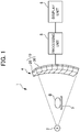
- FIG. 1 is a schematic view of an X-ray CT device (X-ray inspection device) 1 which is an embodiment of a radiation inspection device according to the present invention. It should be noted that the present invention is not limited to the X-ray CT device 1, but may also be a radiation inspection device using other radiation such as gamma rays, etc.
- the X-ray CT device 1 includes an X-ray emitting device (radiation emitting device) 2, a platform 3 on which a subject B is placed, and an X-ray detection device (radiation detection device) 4 arranged along a circumference centered on the X-ray emitting device 2.
- the X-ray detection device 4 includes a plurality of X-ray detection units (radiation detection units) 10.
- FIG. 2 is a cross-sectional perspective view of one X-ray detection unit 10 according to a first embodiment.
- Each X-ray detection unit 10 includes a collimator 20 and a plurality of X-ray detection elements (radiation detection elements) 30.
- the X-ray detection elements 30 are arranged at intervals (pitch) of about 0.1 to 2.00 mm.
- the X-ray detection elements 30 are arranged in correspondence with respective X-ray transmission sections 21 provided to the collimator 20 described below.
- the X-ray detection elements 30 may be of an indirect conversion type or a direct conversion type.
- An X-ray detection element 30 of an indirect conversion type is composed of a scintillator and an optical sensor such as a photomultiplier, converting incident X-rays into light by the scintillator and converting the converted light into electrical signals by a photoelectric conversion element.
- An X-ray detection element 30 of a direct conversion type is composed of a plurality of cadmium telluride (CdTe) semiconductor devices, and converts incident X-rays directly into electrical signals.
- CdTe cadmium telluride
- the collimator 20 includes an X-ray blocking section (radiation blocking section) 22 in the form of a plate with a predetermined thickness, and a plurality of columnar X-ray transmission sections (radiation transmission sections) 21 arranged in a grid and penetrating the X-ray blocking section 22.
- the X-ray blocking section 22 is made of a material with a high blocking rate (low transmittance) against X-rays and visible light.
- the material of the X-ray blocking section 22 is tin.
- the material of the X-ray blocking section 22 may be a metal with a high atomic number, high X-ray blocking capability (stopping power) against visible light and X-rays, or which is heavy, such as molybdenum, tantalum, lead, tungsten, etc., or an alloy containing these heavy metals.
- the melting point of tin is 231°C, and when carrying out the production method described below, the use of a metal with a comparatively low melting point about the same as that of tin facilitates production.
- a thickness b of the X-ray blocking section 22 is about 1 to 50 mm.
- the X-ray transmission section 21 is, for example, columnar in shape, solid, and a central axis A of the column extends in a direction respectively toward the X-ray emitting device 2 or the subject B.
- a respective X-ray detection element 30 which is tightly attached so that visible light cannot enter between the X-ray transmission section 21 and the X-ray detection element 30.
- a radius R of the X-ray transmission section 21 is about 0.07 to 0.2 mm, and the depth of the X-ray transmission section 21 is about 1 to 50 mm, equal to the thickness b of the X-ray blocking section 22.
- the radius R of the X-ray transmission section 21 is of a smaller shape (elongated shape with a high aspect ratio) compared to the depth b.
- the X-ray transmission section 21 is not limited to a columnar shape, but may also be in the shape of an elliptical column or a polygonal column.
- the X-ray transmission section 21 is made of a material with a low blocking rate (high transmittance) against X-rays and a high blocking rate (low transmittance) against visible light, such as carbon.
- the material may be a material other than carbon, having an atomic number smaller than that of the X-ray blocking section 22, a low X-ray blocking rate, or which is light, such as aluminum.
- the melting point of the material of the X-ray transmission section 21 is higher than the melting point of the material of the X-ray blocking section 22.
- X-rays emitted by the X-ray emitting device 2 are irradiated onto the subject B.
- the light irradiated onto the subject B is transmitted through the subject B, where the light is partially scattered.
- X-rays proceeding straight after passing through the subject B and scattered X-rays which have been scattered in the subject B reach the collimator 20.
- X-rays other than the X-rays that enter the X-ray transmission section 21 are blocked by the X-ray blocking section 22 due to the high X-ray blocking rate of the X-ray blocking section 22.
- the X-rays that have reached the X-ray transmission section 21 enter the X-ray transmission section 21, as the X-ray blocking rate of the X-ray transmission section is low. Visible light is blocked due to the high blocking rate against visible light of the X-ray transmission section 21.
- the X-rays that have reached the X-ray detection element 30 are converted into light by the scintillator, and the converted light is converted into an electrical signal by the photoelectric conversion element.
- the X-rays are converted directly into an electrical signal.
- Intensity information of the X-rays converted into an electrical signal is processed by a processing unit 5 to generate X-ray CT image data, and an X-ray CT image is displayed by a display unit 6.
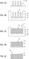
- FIG. 3 is a drawing describing a method for producing the collimator 20 according to the first embodiment.
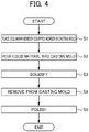
- FIG. 4 is a flowchart describing the method for producing the collimator 20 according to the first embodiment.
- the collimator 20 according to the first embodiment is produced by casting.
- a columnar member-equipped member 24 in which a plurality of columnar members for forming the X-ray transmission section 21 are provided upright on a support substrate 23 is prepared ( FIG. 3A ) .
- columnar members 21a and the support substrate 23 in other words the columnar member-equipped member 24 as a whole, is made of carbon.
- the columnar members 21a and the support substrate 23 may be separate pieces.
- the columnar member-equipped member 24 is placed inside a casting mold 40 ( FIG. 3B , FIG. 4 (Step S1)).
- the melting point of tin is 231°C.
- the temperature is lowered to the melting point or less in order to solidify the X-ray blocking section 22 ( FIG. 4 (Step S3)).
- the X-ray blocking section 22, having solidified to become integrated with the columnar member-equipped member 24, is removed from the casting mold 40 ( FIG. 3D , FIG. 4 (Step S4)).
- At least the surface of the support substrate 23 of the integrated columnar member-equipped member 24 and X-ray blocking section 22 is polished to remove the support substrate 23 ( FIG. 3E , FIG. 4 (Step S5)).
- the collimator 20 according to the present embodiment is thus produced.
- FIG. 6 is a graph showing the X-ray absorption rates of carbon (C), aluminum (Al), and copper (Cu), each with a thickness of 30 mm. As illustrated, carbon (C), aluminum (Al), and copper (Cu) have low absorption rates of high-energy X-rays, and high absorption rates of low-energy X-rays.
- carbon has a high selective absorption of low-energy X-rays, and while the absorption rate is approximately 0% at an energy of about 150 keV or more, the absorption rate increases drastically when the energy is lower than about 150 keV. This selective absorption becomes higher in the order of copper (Cu), aluminum (Al), and carbon (C).
- FIG. 7 is a graph showing a count value of X-rays emitted by an X-ray emitting device 2 using an X-ray source having the spectrum shown in FIG. 5 , irradiated onto a subject B, and detected by an X-ray detection element 30.
- Count value P represents a case in which a collimator 20 of the embodiment that has actually been produced is arranged between the X-ray detection element 30 and the subject B
- count value Q represents a case in which the collimator itself is not arranged between the X-ray detection element 30 and the subject B.
- a collimator was used in which tin with a thickness of 30 mm was used as the X-ray blocking section 22, and the X-ray transmission section 21 was formed by filling through holes with a diameter of 0.2 mm and a length of 30 mm with carbon.
- the count value Q in the case in which the collimator itself is not arranged between the X-ray detection element 30 and the subject B, the X-rays detected by the X-ray detection element 30 include a large amount of low-energy X-rays which have been scattered in the subject B and thus have reduced energy. Therefore, a high-resolution X-ray image cannot be obtained.
- the collimator 20 filled with carbon of the embodiment that has actually been produced is arranged between the X-ray detection element 30 and the subject B, the low-energy X-rays that have been scattered in the subject B are absorbed (blocked) in the X-ray transmission section 21, as shown in FIG. 6 . Therefore, as shown by the count value P, X-rays with an energy distribution (shape of the curve) similar to the shape of the X-ray spectrum represented by the simulation-calculated values ( FIG. 5 ) can be detected.
- scattered X-rays can better be removed, which decreases noise included in the X-rays detected by the X-ray detection element 30 and allows for a high-resolution X-ray image to be obtained.
- the X-ray transmission section 21 is not limited to carbon, but may be made of other appropriately selected materials such as aluminum and copper shown in FIG. 6 , allowing for light of an undesired wavelength to be removed depending on the application.
- the X-ray transmission section 21 of the collimator 20 is filled with carbon and is solid.
- the collimator 20 and the X-ray detection element 30 are tightly attached to prevent visible light from entering between them.
- the X-ray blocking section is made of a metal with a high atomic number. It therefore has a high hardness, which makes it difficult to open fine through holes with low aspect ratios, leading to high production costs and long production time. Further, swarf resulting from drilling the through holes may get caught up in the drill as it continues to rotate, further complicating the opening of precise and fine through holes.
- the collimator 20 of the present embodiment is made by inserting a support substrate 23 having columnar X-ray transmission sections 21 provided upright thereon into a casting mold 40, into which molten X-ray blocking section 22 material is poured and solidified.
- a support substrate 23 having columnar X-ray transmission sections 21 provided upright thereon into a casting mold 40, into which molten X-ray blocking section 22 material is poured and solidified.
- X-ray transmission sections 21 that are fine and have small aspect ratios can easily be produced. This allows for the production of a collimator 20 with a higher directionality.
- the second embodiment differs from the first embodiment in terms of the structure and production method of a collimator 120. Since the other aspects are the same as in the first embodiment, description of the same portions is omitted.
- Tin is used for the X-ray blocking section 22 of the collimator 20 of the first embodiment, but for an X-ray blocking section 122 of the collimator 120 of the second embodiment, mercury, which is a liquid at room temperature, is used.
- FIG. 8 is a drawing describing a method for producing the collimator 120 according to the second embodiment.
- the collimator 120 of the second embodiment includes a container 150, a liquid X-ray blocking section 122 of mercury enclosed within the container 150, and a plurality of X-ray transmission sections 121 made of a solid material with a lower X-ray blocking rate than the X-ray blocking section 122 such as carbon and having upper and lower ends fixed to two opposite surfaces in the container 150.
- the container 150 includes a lower container 151 with an open top and a lid 152 that covers the top of the lower container 151.
- the inner surface of the bottom of the lower container 151 is provided with a plurality of blind holes 151a into which the lower ends of the columnar X-ray transmission sections 21 can be inserted to be held in place.
- the lower surface of the lid 152 is provided, at positions corresponding to the blind holes 151a, with blind holes 152a into which the upper ends of the columnar X-ray transmission sections 21 can be inserted to be held in place.
- the material of the container 150 is preferably a material that is rigid and resistant to corrosion by mercury, such as resin, glass, or ceramic.
- the collimator 120 according to the second embodiment is produced as described below.
- the X-ray transmission sections 21 are inserted into the blind holes 151a of the lower container 151 to be held in place ( FIG. 8 A) .
- Mercury, which is to constitute the X-ray blocking section 22, is poured into the lower container 151 ( FIG. 8 B) .
- the upper ends of the X-ray transmission sections 121 protrude above the surface of the mercury.
- the lid 152 is placed on the lower container 151 to enclose the mercury within the container 150. At this time, the upper ends of the X-ray transmission sections 121 are fitted into the blind holes 152a of the lid 152 ( FIG. 8C ).
- the collimator 120 of the second embodiment including the liquid X-ray blocking section 122 of mercury enclosed within the container 150, and the plurality of X-ray transmission sections 121 made of a solid material with a lower X-ray blocking rate than the X-ray blocking section 122 such as carbon and having upper and lower ends fixed to two opposite surfaces in the container, is produced.
- changing the shape of the container 150 allows for production of collimators 120 of various shapes. It is thus possible to easily produce, for example, a curved collimator 120.
- the material of the container 150 itself is a plastic material, deformation after production is also easy, allowing for the production of a highly versatile collimator 120.
Landscapes
- Health & Medical Sciences (AREA)
- Life Sciences & Earth Sciences (AREA)
- Engineering & Computer Science (AREA)
- Medical Informatics (AREA)
- Physics & Mathematics (AREA)
- High Energy & Nuclear Physics (AREA)
- Pathology (AREA)
- Heart & Thoracic Surgery (AREA)
- Biophysics (AREA)
- Veterinary Medicine (AREA)
- Nuclear Medicine, Radiotherapy & Molecular Imaging (AREA)
- Optics & Photonics (AREA)
- Public Health (AREA)
- Radiology & Medical Imaging (AREA)
- Biomedical Technology (AREA)
- General Health & Medical Sciences (AREA)
- Molecular Biology (AREA)
- Surgery (AREA)
- Animal Behavior & Ethology (AREA)
- Computer Vision & Pattern Recognition (AREA)
- Pulmonology (AREA)
- Theoretical Computer Science (AREA)
- Spectroscopy & Molecular Physics (AREA)
- General Engineering & Computer Science (AREA)
- Measurement Of Radiation (AREA)
- Apparatus For Radiation Diagnosis (AREA)
Abstract
Description
- The present invention relates to a collimator, radiation detection device, and radiation inspection device.
- Radiation inspection devices that perform nondestructive testing, such as, for example, X-ray computed tomography (CT) devices, irradiate a subject with radiation and generate a CT image based on the radiation transmitted through the subject.
- This kind of radiation inspection device is equipped with a radiation emitting device and a radiation detection device. The radiation irradiated onto the subject is partially scattered inside the subject. When the radiation detection device detects scattered radiation, detection accuracy deteriorates. In order to remove this scattered radiation, the radiation detection device is provided with a collimator.
- Collimators are conventionally provided with a plurality of through holes that transmit radiation. When radiation passes through these through holes, radiation that enters a through hole at an angle equal to or greater than a predetermined angle relative to a central axis of the through hole collides with the sidewall of the through hole. Since scattered radiation that degrades detection accuracy is oriented in various directions, it is removed when passing through the through holes, resulting in a more accurate CT image compared to when no collimator is provided (See, for example, Patent Document 1).
- Patent Document 1: Japanese Unexamined Patent Application, Publication No.
2018-00496 - However, as not all of the scattered radiation is removed from the radiation that has passed through the through holes, it still contains a certain amount of scattered radiation.
- It is an object of the present invention to provide a collimator, a radiation detection device, and a radiation inspection device that are capable of further removing scattered radiation.
- In order to solve the above problem, the present invention provides the following.
- A collimator including a radiation blocking section, and a radiation transmission section that has a lower radiation blocking rate than the radiation blocking section, penetrates the radiation blocking section, and is solid.
- The radiation transmission section may be made of a material that has a high visible light transmittance.
- The radiation transmission section may be made of carbon.
- The radiation blocking section may be made of tin.
- Further, in order to solve the above problem, the present invention provides the following.
- A collimator including a liquid radiation blocking section, a radiation transmission section that has a lower radiation blocking rate than the radiation blocking section and penetrates the radiation blocking section, and a container that encloses the radiation blocking section and the radiation transmission section.
- In addition, in order to solve the above problem, the present invention provides the following.
- A radiation detection device including the collimator according to any of the above descriptions, and a detection element arranged in correspondence with the radiation transmission section.
- Further, in order to solve the above problem, the present invention provides the following.
- A radiation inspection device including a radiation emitting unit that irradiates a subject with radiation, the collimator according to any of the above descriptions, and a detection element arranged in correspondence with the radiation transmission section.
- According to the present invention, eliminating the need for a light-blocking plate makes it possible to provide a collimator, a radiation detection device, and a radiation inspection device, the production process of which can be simplified, and which can be produced in a more compact form.
-
-
FIG. 1 is a schematic view of an X-ray CT device 1 which is an embodiment of a radiation inspection device; -
FIG. 2A is a cross-sectional perspective view of oneX-ray detection unit 10 according to a first embodiment; -
FIG. 2B is a cross-sectional perspective view of oneX-ray detection unit 10 according to a first embodiment; -
FIG. 2C is a cross-sectional perspective view of oneX-ray detection unit 10 according to a first embodiment; -
FIG. 2D is a cross-sectional perspective view of oneX-ray detection unit 10 according to a first embodiment; -
FIG. 2E is a cross-sectional perspective view of oneX-ray detection unit 10 according to a first embodiment; -
FIG. 3 is a drawing describing a method for producing acollimator 20 according to the first embodiment; -
FIG. 4 is a flowchart describing the method for producing thecollimator 20 according to the first embodiment; -
FIG. 5 is a graph showing simulation-calculated values of an X-ray spectrum; -
FIG. 6 is a graph showing X-ray absorption rates of carbon (C), aluminum (Al), and copper (Cu); -
FIG. 7 is a graph showing a count value of X-rays emitted by anX-ray emitting device 2, irradiated onto a subject B, and detected by anX-ray detection element 30; -
FIG. 8A is a drawing describing a method for producing acollimator 120 according to a second embodiment; -
FIG. 8B is a drawing describing a method for producing acollimator 120 according to a second embodiment; and -
FIG. 8C is a drawing describing a method for producing acollimator 120 according to a second embodiment. -
FIG. 1 is a schematic view of an X-ray CT device (X-ray inspection device) 1 which is an embodiment of a radiation inspection device according to the present invention. It should be noted that the present invention is not limited to the X-ray CT device 1, but may also be a radiation inspection device using other radiation such as gamma rays, etc. - The X-ray CT device 1 includes an X-ray emitting device (radiation emitting device) 2, a
platform 3 on which a subject B is placed, and an X-ray detection device (radiation detection device) 4 arranged along a circumference centered on theX-ray emitting device 2. TheX-ray detection device 4 includes a plurality of X-ray detection units (radiation detection units) 10. -
FIG. 2 is a cross-sectional perspective view of oneX-ray detection unit 10 according to a first embodiment. EachX-ray detection unit 10 includes acollimator 20 and a plurality of X-ray detection elements (radiation detection elements) 30. - The
X-ray detection elements 30 are arranged at intervals (pitch) of about 0.1 to 2.00 mm. TheX-ray detection elements 30 are arranged in correspondence with respectiveX-ray transmission sections 21 provided to thecollimator 20 described below. - The
X-ray detection elements 30 may be of an indirect conversion type or a direct conversion type. AnX-ray detection element 30 of an indirect conversion type is composed of a scintillator and an optical sensor such as a photomultiplier, converting incident X-rays into light by the scintillator and converting the converted light into electrical signals by a photoelectric conversion element. - An
X-ray detection element 30 of a direct conversion type is composed of a plurality of cadmium telluride (CdTe) semiconductor devices, and converts incident X-rays directly into electrical signals. - The
collimator 20 includes an X-ray blocking section (radiation blocking section) 22 in the form of a plate with a predetermined thickness, and a plurality of columnar X-ray transmission sections (radiation transmission sections) 21 arranged in a grid and penetrating theX-ray blocking section 22. - The
X-ray blocking section 22 is made of a material with a high blocking rate (low transmittance) against X-rays and visible light. - In the embodiment, the material of the
X-ray blocking section 22 is tin. However, this is not a limitation, and the material of theX-ray blocking section 22 may be a metal with a high atomic number, high X-ray blocking capability (stopping power) against visible light and X-rays, or which is heavy, such as molybdenum, tantalum, lead, tungsten, etc., or an alloy containing these heavy metals. It should be noted that the melting point of tin is 231°C, and when carrying out the production method described below, the use of a metal with a comparatively low melting point about the same as that of tin facilitates production. A thickness b of theX-ray blocking section 22 is about 1 to 50 mm. - In the embodiment, the
X-ray transmission section 21 is, for example, columnar in shape, solid, and a central axis A of the column extends in a direction respectively toward theX-ray emitting device 2 or the subject B. To the face of theX-ray transmission section 21 on the opposite side from theX-ray emitting device 2 or the subject B is provided with a respectiveX-ray detection element 30 which is tightly attached so that visible light cannot enter between theX-ray transmission section 21 and theX-ray detection element 30. - A radius R of the
X-ray transmission section 21 is about 0.07 to 0.2 mm, and the depth of theX-ray transmission section 21 is about 1 to 50 mm, equal to the thickness b of theX-ray blocking section 22. In other words, the radius R of theX-ray transmission section 21 is of a smaller shape (elongated shape with a high aspect ratio) compared to the depth b. It should be noted that theX-ray transmission section 21 is not limited to a columnar shape, but may also be in the shape of an elliptical column or a polygonal column. - The
X-ray transmission section 21 is made of a material with a low blocking rate (high transmittance) against X-rays and a high blocking rate (low transmittance) against visible light, such as carbon. - However, this is not a limitation, and the material may be a material other than carbon, having an atomic number smaller than that of the
X-ray blocking section 22, a low X-ray blocking rate, or which is light, such as aluminum. - Further, when carrying out the production method described below, the melting point of the material of the
X-ray transmission section 21 is higher than the melting point of the material of theX-ray blocking section 22. - Next, an operation of the X-ray CT device 1 according to the present embodiment will be described.
- X-rays emitted by the
X-ray emitting device 2 are irradiated onto the subject B. The light irradiated onto the subject B is transmitted through the subject B, where the light is partially scattered. X-rays proceeding straight after passing through the subject B and scattered X-rays which have been scattered in the subject B reach thecollimator 20. - Of the X-rays that have reached the
collimator 20, X-rays other than the X-rays that enter theX-ray transmission section 21 are blocked by theX-ray blocking section 22 due to the high X-ray blocking rate of theX-ray blocking section 22. - Meanwhile, the X-rays that have reached the
X-ray transmission section 21 enter theX-ray transmission section 21, as the X-ray blocking rate of the X-ray transmission section is low. Visible light is blocked due to the high blocking rate against visible light of theX-ray transmission section 21. - Of the X-rays that have entered the inside of the
X-ray transmission section 21, scattered X-rays that are at an angle equal to or greater than a predetermined angle relative to the central axis A of theX-ray transmission section 21 will hit the side surface of theX-ray transmission section 21 before passing through theX-ray transmission section 21, and are thus blocked by theX-ray blocking section 22. - As such, of the X-rays that have entered the
X-ray transmission section 21, only X-rays travelling sufficiently straight pass through theX-ray transmission section 21 and reach theX-ray detection element 30. - In the case of an indirect conversion type
X-ray detection element 30, the X-rays that have reached theX-ray detection element 30 are converted into light by the scintillator, and the converted light is converted into an electrical signal by the photoelectric conversion element. In the case of a direct typeX-ray detection element 30, the X-rays are converted directly into an electrical signal. - Intensity information of the X-rays converted into an electrical signal is processed by a
processing unit 5 to generate X-ray CT image data, and an X-ray CT image is displayed by adisplay unit 6. -
FIG. 3 is a drawing describing a method for producing thecollimator 20 according to the first embodiment.FIG. 4 is a flowchart describing the method for producing thecollimator 20 according to the first embodiment. Thecollimator 20 according to the first embodiment is produced by casting. - First, a columnar member-equipped
member 24 in which a plurality of columnar members for forming theX-ray transmission section 21 are provided upright on asupport substrate 23 is prepared (FIG. 3A ) . - In the first embodiment,
columnar members 21a and thesupport substrate 23, in other words the columnar member-equippedmember 24 as a whole, is made of carbon. However, this is not a limitation, and thecolumnar members 21a and thesupport substrate 23 may be separate pieces. - The columnar member-equipped
member 24 is placed inside a casting mold 40 (FIG. 3B ,FIG. 4 (Step S1)). - The material of the
X-ray blocking section 22, which in the embodiment is tin, which has been heated to its melting point or more to become liquid, is poured into the casting mold 40 (FIG. 3c ,FIG. 4 (Step S2)). The melting point of tin is 231°C. - The temperature is lowered to the melting point or less in order to solidify the X-ray blocking section 22 (
FIG. 4 (Step S3)). - The
X-ray blocking section 22, having solidified to become integrated with the columnar member-equippedmember 24, is removed from the casting mold 40 (FIG. 3D ,FIG. 4 (Step S4)). - At least the surface of the
support substrate 23 of the integrated columnar member-equippedmember 24 andX-ray blocking section 22 is polished to remove the support substrate 23 (FIG. 3E ,FIG. 4 (Step S5)). - The
collimator 20 according to the present embodiment is thus produced. - The effect of the present embodiment is described below.
- (1)
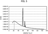
FIG. 5 is a graph showing simulation-calculated values of an X-ray spectrum of one example of an X-ray source that is preferable used as theX-ray emitting device 2, wherein the Y-axis represents X-ray dose and the X-axis represents X-ray energy. As illustrated, in the X-ray spectrum according to this example, the dose peaks at around 22 keV of energy, and the dose decreases as the energy becomes higher. The dose also decreases at a lower energy than around 22 keV. -
FIG. 6 is a graph showing the X-ray absorption rates of carbon (C), aluminum (Al), and copper (Cu), each with a thickness of 30 mm. As illustrated, carbon (C), aluminum (Al), and copper (Cu) have low absorption rates of high-energy X-rays, and high absorption rates of low-energy X-rays. - In particular, carbon has a high selective absorption of low-energy X-rays, and while the absorption rate is approximately 0% at an energy of about 150 keV or more, the absorption rate increases drastically when the energy is lower than about 150 keV. This selective absorption becomes higher in the order of copper (Cu), aluminum (Al), and carbon (C).
-
FIG. 7 is a graph showing a count value of X-rays emitted by anX-ray emitting device 2 using an X-ray source having the spectrum shown inFIG. 5 , irradiated onto a subject B, and detected by anX-ray detection element 30. Count value P represents a case in which acollimator 20 of the embodiment that has actually been produced is arranged between theX-ray detection element 30 and the subject B, and count value Q represents a case in which the collimator itself is not arranged between theX-ray detection element 30 and the subject B. As thecollimator 20, a collimator was used in which tin with a thickness of 30 mm was used as theX-ray blocking section 22, and theX-ray transmission section 21 was formed by filling through holes with a diameter of 0.2 mm and a length of 30 mm with carbon. - As shown by the count value Q, in the case in which the collimator itself is not arranged between the
X-ray detection element 30 and the subject B, the X-rays detected by theX-ray detection element 30 include a large amount of low-energy X-rays which have been scattered in the subject B and thus have reduced energy. Therefore, a high-resolution X-ray image cannot be obtained. - By contrast, in the case in which the
collimator 20 filled with carbon of the embodiment that has actually been produced is arranged between theX-ray detection element 30 and the subject B, the low-energy X-rays that have been scattered in the subject B are absorbed (blocked) in theX-ray transmission section 21, as shown inFIG. 6 . Therefore, as shown by the count value P, X-rays with an energy distribution (shape of the curve) similar to the shape of the X-ray spectrum represented by the simulation-calculated values (FIG. 5 ) can be detected. - In other words, according to the
collimator 20 of the embodiment, scattered X-rays can better be removed, which decreases noise included in the X-rays detected by theX-ray detection element 30 and allows for a high-resolution X-ray image to be obtained. - It should be noted that the
X-ray transmission section 21 is not limited to carbon, but may be made of other appropriately selected materials such as aluminum and copper shown inFIG. 6 , allowing for light of an undesired wavelength to be removed depending on the application. - (2) Conventional X-ray detection devices are provided with light-blocking structures to prevent visible light from entering the X-ray detection element. In the case of scintillators in particular, since X-rays are first converted into visible light to be detected, the need to prevent exterior visible light from entering makes the light-blocking structure important.
- However, in the present embodiment, the
X-ray transmission section 21 of thecollimator 20 is filled with carbon and is solid. In addition, thecollimator 20 and theX-ray detection element 30 are tightly attached to prevent visible light from entering between them. - Accordingly, since visible light cannot reach the
X-ray detection element 30, there is no need to provide a separate light-blocking structure. This can reduce production costs and shorten production time. - (3) For the sake of comparison, it is possible to, for example, provide an X-ray transmission section by opening through holes in an X-ray blocking section by drilling or the like.
- However, in order to be able to block X-rays, the X-ray blocking section is made of a metal with a high atomic number. It therefore has a high hardness, which makes it difficult to open fine through holes with low aspect ratios, leading to high production costs and long production time. Further, swarf resulting from drilling the through holes may get caught up in the drill as it continues to rotate, further complicating the opening of precise and fine through holes.
- However, the
collimator 20 of the present embodiment is made by inserting asupport substrate 23 having columnarX-ray transmission sections 21 provided upright thereon into a castingmold 40, into which moltenX-ray blocking section 22 material is poured and solidified. As such, unlike a method of opening through holes by drilling,X-ray transmission sections 21 that are fine and have small aspect ratios can easily be produced. This allows for the production of acollimator 20 with a higher directionality. - Next, a second embodiment of the present invention will be described. The second embodiment differs from the first embodiment in terms of the structure and production method of a
collimator 120. Since the other aspects are the same as in the first embodiment, description of the same portions is omitted. Tin is used for theX-ray blocking section 22 of thecollimator 20 of the first embodiment, but for an X-ray blocking section 122 of thecollimator 120 of the second embodiment, mercury, which is a liquid at room temperature, is used. -
FIG. 8 is a drawing describing a method for producing thecollimator 120 according to the second embodiment. As shown inFIG. 8C , thecollimator 120 of the second embodiment includes acontainer 150, a liquid X-ray blocking section 122 of mercury enclosed within thecontainer 150, and a plurality of X-ray transmission sections 121 made of a solid material with a lower X-ray blocking rate than the X-ray blocking section 122 such as carbon and having upper and lower ends fixed to two opposite surfaces in thecontainer 150. - The
container 150 includes alower container 151 with an open top and alid 152 that covers the top of thelower container 151. The inner surface of the bottom of thelower container 151 is provided with a plurality ofblind holes 151a into which the lower ends of the columnarX-ray transmission sections 21 can be inserted to be held in place. - The lower surface of the
lid 152 is provided, at positions corresponding to theblind holes 151a, withblind holes 152a into which the upper ends of the columnarX-ray transmission sections 21 can be inserted to be held in place. - The material of the
container 150 is preferably a material that is rigid and resistant to corrosion by mercury, such as resin, glass, or ceramic. - The
collimator 120 according to the second embodiment is produced as described below. - The
X-ray transmission sections 21 are inserted into theblind holes 151a of thelower container 151 to be held in place (FIG. 8 A) . Mercury, which is to constitute theX-ray blocking section 22, is poured into the lower container 151 (FIG. 8 B) . At this time, the upper ends of the X-ray transmission sections 121 protrude above the surface of the mercury. - The
lid 152 is placed on thelower container 151 to enclose the mercury within thecontainer 150. At this time, the upper ends of the X-ray transmission sections 121 are fitted into theblind holes 152a of the lid 152 (FIG. 8C ). - In this way, the
collimator 120 of the second embodiment including the liquid X-ray blocking section 122 of mercury enclosed within thecontainer 150, and the plurality of X-ray transmission sections 121 made of a solid material with a lower X-ray blocking rate than the X-ray blocking section 122 such as carbon and having upper and lower ends fixed to two opposite surfaces in the container, is produced. - According to the
collimator 120 of the second embodiment, in addition to the effects of the first embodiment, changing the shape of thecontainer 150 allows for production ofcollimators 120 of various shapes. It is thus possible to easily produce, for example, acurved collimator 120. - In addition, if the material of the
container 150 itself is a plastic material, deformation after production is also easy, allowing for the production of a highlyversatile collimator 120. -
- 1 X-ray CT device (radiation inspection device)
- 2 X-ray emitting device (radiation emitting device)
- 3 Platform
- 4 X-ray detection device (radiation detection device)
- 5 Processing unit
- 6 Display unit
- 10 X-ray detection unit (radiation detection unit)
- 20 Collimator
- 21a Columnar member
- 21 X-ray transmission section (radiation transmission section)
- 22 X-ray blocking section (radiation blocking section)
- 23 Support substrate
- 24 Columnar member-equipped member
- 30 X-ray detection element (radiation detection element)
- 40 Casting mold
- 120 Collimator
- 121 X-ray transmission section (radiation transmission section)
- 122 X-ray blocking section (radiation blocking section) 150 Container
- 151 Lower container
- 151a Blind hole
- 152 Lid
- 152a Blind hole
Claims (7)
- A collimator comprising:a radiation blocking section; anda radiation transmission section that has a lower radiation blocking rate than the radiation blocking section, penetrates the radiation blocking section, and is solid.
- The collimator according to Claim 1, wherein the radiation transmission section is made of a material with a high visible light transmittance.
- The collimator according to Claim 1 or 2, wherein the radiation transmission section is made of carbon.
- The collimator according to any one of Claims 1 to 3, wherein the radiation blocking section is made of tin.
- A collimator comprising:a liquid radiation blocking section;a radiation transmission section that has a lower radiation blocking rate than the radiation blocking section and penetrates the radiation blocking section; anda container that encloses the radiation blocking section and the radiation transmission section.
- A radiation detection device comprising:the collimator according to any one of Claims 1 to 5; anda detection element arranged in correspondence with the radiation transmission section.
- A radiation inspection device comprising:a radiation emitting unit configured to irradiate a subject with radiation;the collimator according to any one of Claims 1 to 5 into which radiation that has passed through the subject enters; anda detection element arranged in correspondence with the radiation transmission section.
Applications Claiming Priority (1)
| Application Number | Priority Date | Filing Date | Title |
|---|---|---|---|
| PCT/JP2018/007361 WO2019167145A1 (en) | 2018-02-27 | 2018-02-27 | Collimator, radiation detection device, and radiation inspection device |
Publications (4)
| Publication Number | Publication Date |
|---|---|
| EP3760128A1 true EP3760128A1 (en) | 2021-01-06 |
| EP3760128A4 EP3760128A4 (en) | 2021-03-03 |
| EP3760128B1 EP3760128B1 (en) | 2025-10-08 |
| EP3760128C0 EP3760128C0 (en) | 2025-10-08 |
Family
ID=67806026
Family Applications (1)
| Application Number | Title | Priority Date | Filing Date |
|---|---|---|---|
| EP18908188.8A Active EP3760128B1 (en) | 2018-02-27 | 2018-02-27 | Collimator, radiation detection device, and radiation inspection device |
Country Status (7)
| Country | Link |
|---|---|
| US (1) | US11179133B2 (en) |
| EP (1) | EP3760128B1 (en) |
| JP (1) | JP6614685B1 (en) |
| KR (1) | KR102270436B1 (en) |
| CN (1) | CN111770728A (en) |
| TW (1) | TWI699190B (en) |
| WO (1) | WO2019167145A1 (en) |
Families Citing this family (4)
| Publication number | Priority date | Publication date | Assignee | Title |
|---|---|---|---|---|
| WO2022091749A1 (en) * | 2020-11-02 | 2022-05-05 | 株式会社堀場製作所 | Radiation detection module and radiation detection device |
| JP2023081749A (en) | 2021-12-01 | 2023-06-13 | 株式会社ジャパンディスプレイ | optical sensor |
| JP7823925B2 (en) | 2021-12-01 | 2026-03-04 | 株式会社Magnolia White | Optical Sensor |
| JP7851581B2 (en) | 2022-03-16 | 2026-04-27 | 株式会社Magnolia White | Optical sensor |
Family Cites Families (34)
| Publication number | Priority date | Publication date | Assignee | Title |
|---|---|---|---|---|
| US2605427A (en) * | 1948-11-25 | 1952-07-29 | Delhumeau Roger Andre | Diffusion-preventing device for x-rays |
| JPS552295B2 (en) | 1973-05-21 | 1980-01-19 | ||
| US4446570A (en) | 1981-07-17 | 1984-05-01 | Siemens Gammasonics, Inc. | Collimator for a radiation detector and method of making same |
| JPS5971605U (en) * | 1982-11-04 | 1984-05-15 | 株式会社西武工作 | X-ray grid |
| JPS59159403U (en) | 1983-04-08 | 1984-10-25 | 株式会社 西武工作 | X-ray grid |
| US4951305A (en) * | 1989-05-30 | 1990-08-21 | Eastman Kodak Company | X-ray grid for medical radiography and method of making and using same |
| US5581592A (en) * | 1995-03-10 | 1996-12-03 | General Electric Company | Anti-scatter X-ray grid device for medical diagnostic radiography |
| US6177237B1 (en) * | 1998-06-26 | 2001-01-23 | General Electric Company | High resolution anti-scatter x-ray grid and laser fabrication method |
| US6408054B1 (en) | 1999-11-24 | 2002-06-18 | Xerox Corporation | Micromachined x-ray image contrast grids |
| JP2001349992A (en) * | 2000-06-12 | 2001-12-21 | Fuji Photo Film Co Ltd | Method of manufacturing scattered ray eliminating grid |
| US7922923B2 (en) * | 2001-02-01 | 2011-04-12 | Creatv Microtech, Inc. | Anti-scatter grid and collimator designs, and their motion, fabrication and assembly |
| DE10136946A1 (en) * | 2001-07-28 | 2003-02-06 | Philips Corp Intellectual Pty | Scattered radiation grid for an X-ray device |
| US7418082B2 (en) * | 2003-06-01 | 2008-08-26 | Koninklijke Philips Electronics N.V. | Anti-scattering X-ray collimator for CT scanners |
| JP2007054360A (en) * | 2005-08-25 | 2007-03-08 | Hitachi Medical Corp | X-ray ct apparatus |
| US20090003530A1 (en) * | 2005-12-13 | 2009-01-01 | Koninklijke Philips Electronics, N.V. | Anti-Scatter Grid for an X-Ray Device with Non-Uniform Distance and/or Width of the Lamellae |
| SE0600694L (en) | 2006-03-28 | 2007-06-05 | Xcounter Ab | Method of manufacturing a collimator |
| US8331536B2 (en) * | 2009-09-18 | 2012-12-11 | General Electric Company | Apparatus for reducing scattered X-ray detection and method of same |
| US8817946B2 (en) * | 2009-12-16 | 2014-08-26 | Hitachi Medical Corporation | X-ray detector and X-ray CT apparatus |
| US20110261925A1 (en) * | 2010-04-26 | 2011-10-27 | DRTECH Corporation | Grid apparatus and x-ray detecting apparatus |
| JP2012143396A (en) * | 2011-01-12 | 2012-08-02 | Fujifilm Corp | Radiographic grating unit and radiographic system |
| JP2012149982A (en) * | 2011-01-19 | 2012-08-09 | Fujifilm Corp | Lattice unit for radiological imaging, radiological imaging system and manufacturing method for lattice body |
| JP2014006194A (en) | 2012-06-26 | 2014-01-16 | Canon Inc | Manufacturing method of structure |
| US9431141B1 (en) | 2013-04-30 | 2016-08-30 | The United States Of America As Represented By The Secretary Of The Air Force | Reconfigurable liquid attenuated collimator |
| US9405021B2 (en) * | 2013-06-03 | 2016-08-02 | Unfors Raysafe Ab | Detector for detecting x-ray radiation parameters |
| US9719947B2 (en) * | 2013-10-31 | 2017-08-01 | Sigray, Inc. | X-ray interferometric imaging system |
| CN203647371U (en) * | 2013-12-05 | 2014-06-18 | 赛诺威盛科技(北京)有限公司 | Collimator |
| JP2015203571A (en) | 2014-04-10 | 2015-11-16 | 株式会社フジキン | Manufacturing method of grid for scattered x-ray removal |
| JP5824106B2 (en) | 2014-05-07 | 2015-11-25 | ジーイー・メディカル・システムズ・グローバル・テクノロジー・カンパニー・エルエルシー | Method for manufacturing collimator module |
| WO2016111596A1 (en) * | 2015-01-09 | 2016-07-14 | 형재희 | Method for manufacturing x-ray grid |
| JP2016148544A (en) | 2015-02-10 | 2016-08-18 | コニカミノルタ株式会社 | Production method of metal grating for x-ray, x-ray imaging device, and intermediate product of metal grating for x-ray |
| KR101669584B1 (en) * | 2015-04-27 | 2016-10-27 | 주식회사 디알텍 | Apparatus for radiography, method for processing radiography and designing radiation grid |
| JP6776024B2 (en) | 2016-06-30 | 2020-10-28 | キヤノンメディカルシステムズ株式会社 | X-ray detector, X-ray detector module, support member and X-ray CT device |
| CN107685495A (en) * | 2016-08-03 | 2018-02-13 | 上海奕瑞光电子科技股份有限公司 | Possess the carbon fiber product and flat panel detector of anti-scattered ray ability |
| WO2019041223A1 (en) * | 2017-08-31 | 2019-03-07 | Shenzhen United Imaging Healthcare Co., Ltd. | Ct focal point determination method and system |
-
2018
- 2018-02-27 JP JP2018566995A patent/JP6614685B1/en active Active
- 2018-02-27 KR KR1020207026007A patent/KR102270436B1/en active Active
- 2018-02-27 US US16/976,371 patent/US11179133B2/en active Active
- 2018-02-27 EP EP18908188.8A patent/EP3760128B1/en active Active
- 2018-02-27 WO PCT/JP2018/007361 patent/WO2019167145A1/en not_active Ceased
- 2018-02-27 CN CN201880090161.0A patent/CN111770728A/en active Pending
-
2019
- 2019-01-23 TW TW108102490A patent/TWI699190B/en active
Also Published As
| Publication number | Publication date |
|---|---|
| JP6614685B1 (en) | 2019-12-04 |
| US11179133B2 (en) | 2021-11-23 |
| JPWO2019167145A1 (en) | 2020-04-09 |
| TW201936119A (en) | 2019-09-16 |
| WO2019167145A1 (en) | 2019-09-06 |
| US20210045705A1 (en) | 2021-02-18 |
| EP3760128A4 (en) | 2021-03-03 |
| EP3760128B1 (en) | 2025-10-08 |
| KR20200119293A (en) | 2020-10-19 |
| KR102270436B1 (en) | 2021-06-29 |
| CN111770728A (en) | 2020-10-13 |
| TWI699190B (en) | 2020-07-21 |
| EP3760128C0 (en) | 2025-10-08 |
Similar Documents
| Publication | Publication Date | Title |
|---|---|---|
| US11179133B2 (en) | Collimater, radiation detection device, and radiation inspection device | |
| Brouwer | Theory of XRF | |
| Kis et al. | NIPS–NORMA station—A combined facility for neutron-based nondestructive element analysis and imaging at the Budapest Neutron Centre | |
| RU2499252C2 (en) | Apparatus and method for x-ray fluorescence analysis of mineral sample | |
| EP2978377B1 (en) | Method of phase gradient radiography and arrangement of an imaging system for application of the method | |
| EP1811291B1 (en) | Fluorescent x-ray analysis device | |
| JP2008506127A (en) | Short wavelength X-ray diffraction measurement apparatus and method | |
| JPH01503803A (en) | ore analysis | |
| EP1680789B1 (en) | Arrangement for collimating electromagnetic radiation | |
| EP2685247B1 (en) | Wavelength-dispersive x-ray fluorescence analysis device | |
| Romano et al. | A new X-ray pinhole camera for energy dispersive X-ray fluorescence imaging with high-energy and high-spatial resolution | |
| US3448264A (en) | X-ray source and measuring means for backscatter analysis of samples | |
| Gopal et al. | Gamma-ray attenuation coefficient measurements | |
| JP6967312B2 (en) | Collimator manufacturing method | |
| JP2017505437A (en) | Apparatus for measuring the amount of beryllium in radioactive objects | |
| Hennig et al. | Development of a phoswich detector for radioxenon field measurements | |
| KR101444731B1 (en) | Grid integrated with scintillator, method for manufacturing the same, and x-ray detector integrated with grid using the same | |
| Hölzer et al. | X-ray crystal spectroscopy of sub-picosecond laser-produced plasmas beyond 50 keV | |
| Tisseur et al. | Recent improvements in X-ray spectrometry measurements performed at the MADERE facility dedicated to reactor dosimetry requirements | |
| Terekhov et al. | The Konus-Wind and Konus-A instrument response functions and the spectral deconvolution procedure | |
| Vladi Biesuz et al. | Review of INFN activities on characterization and applications of hybrid pixel detectors based on Timepix4 ASIC | |
| Block et al. | X-ray determination of the thickness of thin metal foils | |
| WO2003092465A2 (en) | Bone densitometry and mammography | |
| Chiu et al. | Nondestructive 3D elemental imaging of Edo’s archaeological artifacts via muonic X-ray measurements | |
| CN115755154B (en) | Calibration method for detection efficiency of detector |
Legal Events
| Date | Code | Title | Description |
|---|---|---|---|
| STAA | Information on the status of an ep patent application or granted ep patent |
Free format text: STATUS: THE INTERNATIONAL PUBLICATION HAS BEEN MADE |
|
| PUAI | Public reference made under article 153(3) epc to a published international application that has entered the european phase |
Free format text: ORIGINAL CODE: 0009012 |
|
| STAA | Information on the status of an ep patent application or granted ep patent |
Free format text: STATUS: REQUEST FOR EXAMINATION WAS MADE |
|
| 17P | Request for examination filed |
Effective date: 20200828 |
|
| AK | Designated contracting states |
Kind code of ref document: A1 Designated state(s): AL AT BE BG CH CY CZ DE DK EE ES FI FR GB GR HR HU IE IS IT LI LT LU LV MC MK MT NL NO PL PT RO RS SE SI SK SM TR |
|
| AX | Request for extension of the european patent |
Extension state: BA ME |
|
| A4 | Supplementary search report drawn up and despatched |
Effective date: 20210202 |
|
| RIC1 | Information provided on ipc code assigned before grant |
Ipc: A61B 6/00 20060101ALI20210127BHEP Ipc: A61B 6/03 20060101ALI20210127BHEP Ipc: G21K 1/02 20060101ALI20210127BHEP Ipc: A61B 6/06 20060101AFI20210127BHEP |
|
| DAV | Request for validation of the european patent (deleted) | ||
| DAX | Request for extension of the european patent (deleted) | ||
| STAA | Information on the status of an ep patent application or granted ep patent |
Free format text: STATUS: EXAMINATION IS IN PROGRESS |
|
| 17Q | First examination report despatched |
Effective date: 20230907 |
|
| GRAP | Despatch of communication of intention to grant a patent |
Free format text: ORIGINAL CODE: EPIDOSNIGR1 |
|
| STAA | Information on the status of an ep patent application or granted ep patent |
Free format text: STATUS: GRANT OF PATENT IS INTENDED |
|
| INTG | Intention to grant announced |
Effective date: 20250514 |
|
| GRAS | Grant fee paid |
Free format text: ORIGINAL CODE: EPIDOSNIGR3 |
|
| GRAA | (expected) grant |
Free format text: ORIGINAL CODE: 0009210 |
|
| STAA | Information on the status of an ep patent application or granted ep patent |
Free format text: STATUS: THE PATENT HAS BEEN GRANTED |
|
| AK | Designated contracting states |
Kind code of ref document: B1 Designated state(s): AL AT BE BG CH CY CZ DE DK EE ES FI FR GB GR HR HU IE IS IT LI LT LU LV MC MK MT NL NO PL PT RO RS SE SI SK SM TR |
|
| REG | Reference to a national code |
Ref country code: GB Ref legal event code: FG4D Ref country code: CH Ref legal event code: F10 Free format text: ST27 STATUS EVENT CODE: U-0-0-F10-F00 (AS PROVIDED BY THE NATIONAL OFFICE) Effective date: 20251008 |
|
| REG | Reference to a national code |
Ref country code: DE Ref legal event code: R096 Ref document number: 602018086280 Country of ref document: DE |
|
| REG | Reference to a national code |
Ref country code: IE Ref legal event code: FG4D |
|
| U01 | Request for unitary effect filed |
Effective date: 20251107 |
|
| U07 | Unitary effect registered |
Designated state(s): AT BE BG DE DK EE FI FR IT LT LU LV MT NL PT RO SE SI Effective date: 20251112 |
|
| U20 | Renewal fee for the european patent with unitary effect paid |
Year of fee payment: 9 Effective date: 20260225 |
|
| PGFP | Annual fee paid to national office [announced via postgrant information from national office to epo] |
Ref country code: GB Payment date: 20260220 Year of fee payment: 9 |
|
| PG25 | Lapsed in a contracting state [announced via postgrant information from national office to epo] |
Ref country code: ES Free format text: LAPSE BECAUSE OF FAILURE TO SUBMIT A TRANSLATION OF THE DESCRIPTION OR TO PAY THE FEE WITHIN THE PRESCRIBED TIME-LIMIT Effective date: 20251008 |
|
| PG25 | Lapsed in a contracting state [announced via postgrant information from national office to epo] |
Ref country code: NO Free format text: LAPSE BECAUSE OF FAILURE TO SUBMIT A TRANSLATION OF THE DESCRIPTION OR TO PAY THE FEE WITHIN THE PRESCRIBED TIME-LIMIT Effective date: 20260108 |
|
| PG25 | Lapsed in a contracting state [announced via postgrant information from national office to epo] |
Ref country code: HR Free format text: LAPSE BECAUSE OF FAILURE TO SUBMIT A TRANSLATION OF THE DESCRIPTION OR TO PAY THE FEE WITHIN THE PRESCRIBED TIME-LIMIT Effective date: 20251008 |
|
| PG25 | Lapsed in a contracting state [announced via postgrant information from national office to epo] |
Ref country code: RS Free format text: LAPSE BECAUSE OF FAILURE TO SUBMIT A TRANSLATION OF THE DESCRIPTION OR TO PAY THE FEE WITHIN THE PRESCRIBED TIME-LIMIT Effective date: 20260108 |
|
| PG25 | Lapsed in a contracting state [announced via postgrant information from national office to epo] |
Ref country code: IS Free format text: LAPSE BECAUSE OF FAILURE TO SUBMIT A TRANSLATION OF THE DESCRIPTION OR TO PAY THE FEE WITHIN THE PRESCRIBED TIME-LIMIT Effective date: 20260208 |
|
| PG25 | Lapsed in a contracting state [announced via postgrant information from national office to epo] |
Ref country code: PL Free format text: LAPSE BECAUSE OF FAILURE TO SUBMIT A TRANSLATION OF THE DESCRIPTION OR TO PAY THE FEE WITHIN THE PRESCRIBED TIME-LIMIT Effective date: 20251008 |