EP3760073A1 - Adjustable connectors for use with webbing of patient harness systems and other types of safety belt systems - Google Patents
Adjustable connectors for use with webbing of patient harness systems and other types of safety belt systems Download PDFInfo
- Publication number
- EP3760073A1 EP3760073A1 EP20183780.4A EP20183780A EP3760073A1 EP 3760073 A1 EP3760073 A1 EP 3760073A1 EP 20183780 A EP20183780 A EP 20183780A EP 3760073 A1 EP3760073 A1 EP 3760073A1
- Authority
- EP
- European Patent Office
- Prior art keywords
- webbing
- slots
- aperture
- adjustable connector
- tabs
- Prior art date
- Legal status (The legal status is an assumption and is not a legal conclusion. Google has not performed a legal analysis and makes no representation as to the accuracy of the status listed.)
- Withdrawn
Links
Images


Classifications
-
- A—HUMAN NECESSITIES
- A44—HABERDASHERY; JEWELLERY
- A44B—BUTTONS, PINS, BUCKLES, SLIDE FASTENERS, OR THE LIKE
- A44B11/00—Buckles; Similar fasteners for interconnecting straps or the like, e.g. for safety belts
- A44B11/25—Buckles; Similar fasteners for interconnecting straps or the like, e.g. for safety belts with two or more separable parts
- A44B11/2503—Safety buckles
- A44B11/2546—Details
- A44B11/2553—Attachment of buckle to strap
- A44B11/2557—Attachment of buckle to strap with strap length adjustment
-
- A—HUMAN NECESSITIES
- A44—HABERDASHERY; JEWELLERY
- A44B—BUTTONS, PINS, BUCKLES, SLIDE FASTENERS, OR THE LIKE
- A44B11/00—Buckles; Similar fasteners for interconnecting straps or the like, e.g. for safety belts
- A44B11/25—Buckles; Similar fasteners for interconnecting straps or the like, e.g. for safety belts with two or more separable parts
- A44B11/2503—Safety buckles
- A44B11/2546—Details
- A44B11/2553—Attachment of buckle to strap
-
- A—HUMAN NECESSITIES
- A44—HABERDASHERY; JEWELLERY
- A44B—BUTTONS, PINS, BUCKLES, SLIDE FASTENERS, OR THE LIKE
- A44B11/00—Buckles; Similar fasteners for interconnecting straps or the like, e.g. for safety belts
- A44B11/02—Buckles; Similar fasteners for interconnecting straps or the like, e.g. for safety belts frictionally engaging surface of straps
- A44B11/06—Buckles; Similar fasteners for interconnecting straps or the like, e.g. for safety belts frictionally engaging surface of straps with clamping devices
-
- A—HUMAN NECESSITIES
- A44—HABERDASHERY; JEWELLERY
- A44B—BUTTONS, PINS, BUCKLES, SLIDE FASTENERS, OR THE LIKE
- A44B11/00—Buckles; Similar fasteners for interconnecting straps or the like, e.g. for safety belts
- A44B11/25—Buckles; Similar fasteners for interconnecting straps or the like, e.g. for safety belts with two or more separable parts
- A44B11/2503—Safety buckles
- A44B11/2546—Details
- A44B11/2561—Tongue elements
-
- B—PERFORMING OPERATIONS; TRANSPORTING
- B60—VEHICLES IN GENERAL
- B60R—VEHICLES, VEHICLE FITTINGS, OR VEHICLE PARTS, NOT OTHERWISE PROVIDED FOR
- B60R22/00—Safety belts or body harnesses in vehicles
- B60R22/18—Anchoring devices
- B60R22/20—Anchoring devices adjustable in position, e.g. in height
-
- A—HUMAN NECESSITIES
- A61—MEDICAL OR VETERINARY SCIENCE; HYGIENE
- A61G—TRANSPORT, PERSONAL CONVEYANCES, OR ACCOMMODATION SPECIALLY ADAPTED FOR PATIENTS OR DISABLED PERSONS; OPERATING TABLES OR CHAIRS; CHAIRS FOR DENTISTRY; FUNERAL DEVICES
- A61G3/00—Ambulance aspects of vehicles; Vehicles with special provisions for transporting patients or disabled persons, or their personal conveyances, e.g. for facilitating access of, or for loading, wheelchairs
- A61G3/08—Accommodating or securing wheelchairs or stretchers
- A61G3/0808—Accommodating or securing wheelchairs
-
- A—HUMAN NECESSITIES
- A61—MEDICAL OR VETERINARY SCIENCE; HYGIENE
- A61G—TRANSPORT, PERSONAL CONVEYANCES, OR ACCOMMODATION SPECIALLY ADAPTED FOR PATIENTS OR DISABLED PERSONS; OPERATING TABLES OR CHAIRS; CHAIRS FOR DENTISTRY; FUNERAL DEVICES
- A61G3/00—Ambulance aspects of vehicles; Vehicles with special provisions for transporting patients or disabled persons, or their personal conveyances, e.g. for facilitating access of, or for loading, wheelchairs
- A61G3/08—Accommodating or securing wheelchairs or stretchers
- A61G3/0816—Accommodating or securing stretchers
-
- B—PERFORMING OPERATIONS; TRANSPORTING
- B60—VEHICLES IN GENERAL
- B60R—VEHICLES, VEHICLE FITTINGS, OR VEHICLE PARTS, NOT OTHERWISE PROVIDED FOR
- B60R22/00—Safety belts or body harnesses in vehicles
- B60R22/18—Anchoring devices
- B60R2022/1806—Anchoring devices for buckles
-
- B—PERFORMING OPERATIONS; TRANSPORTING
- B60—VEHICLES IN GENERAL
- B60R—VEHICLES, VEHICLE FITTINGS, OR VEHICLE PARTS, NOT OTHERWISE PROVIDED FOR
- B60R22/00—Safety belts or body harnesses in vehicles
- B60R22/18—Anchoring devices
- B60R2022/1812—Connections between seat belt and buckle tongue
-
- Y—GENERAL TAGGING OF NEW TECHNOLOGICAL DEVELOPMENTS; GENERAL TAGGING OF CROSS-SECTIONAL TECHNOLOGIES SPANNING OVER SEVERAL SECTIONS OF THE IPC; TECHNICAL SUBJECTS COVERED BY FORMER USPC CROSS-REFERENCE ART COLLECTIONS [XRACs] AND DIGESTS
- Y10—TECHNICAL SUBJECTS COVERED BY FORMER USPC
- Y10T—TECHNICAL SUBJECTS COVERED BY FORMER US CLASSIFICATION
- Y10T24/00—Buckles, buttons, clasps, etc.
- Y10T24/40—Buckles
- Y10T24/4002—Harness
- Y10T24/4012—Clamping
- Y10T24/4019—Sliding part or wedge
-
- Y—GENERAL TAGGING OF NEW TECHNOLOGICAL DEVELOPMENTS; GENERAL TAGGING OF CROSS-SECTIONAL TECHNOLOGIES SPANNING OVER SEVERAL SECTIONS OF THE IPC; TECHNICAL SUBJECTS COVERED BY FORMER USPC CROSS-REFERENCE ART COLLECTIONS [XRACs] AND DIGESTS
- Y10—TECHNICAL SUBJECTS COVERED BY FORMER USPC
- Y10T—TECHNICAL SUBJECTS COVERED BY FORMER US CLASSIFICATION
- Y10T24/00—Buckles, buttons, clasps, etc.
- Y10T24/40—Buckles
- Y10T24/4079—Sliding part of wedge
- Y10T24/4084—Looped strap
-
- Y—GENERAL TAGGING OF NEW TECHNOLOGICAL DEVELOPMENTS; GENERAL TAGGING OF CROSS-SECTIONAL TECHNOLOGIES SPANNING OVER SEVERAL SECTIONS OF THE IPC; TECHNICAL SUBJECTS COVERED BY FORMER USPC CROSS-REFERENCE ART COLLECTIONS [XRACs] AND DIGESTS
- Y10—TECHNICAL SUBJECTS COVERED BY FORMER USPC
- Y10T—TECHNICAL SUBJECTS COVERED BY FORMER US CLASSIFICATION
- Y10T24/00—Buckles, buttons, clasps, etc.
- Y10T24/47—Strap-end-attaching devices
- Y10T24/4736—Buckle connected
Definitions
- Embodiments of the present technology generally relate to adjustable connectors for use with patient harness systems and other types of safety belt systems.
- Patient transport apparatuses are used to transport patients in ambulances, other types of vehicles, hospitals, and other types of facilities.
- Various types of patient transport apparatuses exist, such as, but not limited to, stretchers, cots, wheelchairs, hospital beds, and/or the like.
- harness systems are often used to restrain patients to patient transport apparatuses. Harness systems may also be used to restrain medical personnel to their seats within ambulances and other emergency vehicles.
- Such harness systems should preferably be easily adjustable so that they readily accommodate use with patients and medical personnel of different sizes, e.g., different heights, weights and girths.
- Adjustable connectors which include a metal or alloy tongue (adapted to be received and locked in a buckle) and a metal or alloy lock bar (adapted to lock the connector in place) are typically used to allow for such adjustability.
- harness systems should be sufficiently strong and lockable to withstand certain crash events. More specifically, they may also need to meet applicable safety standards, such as, but not limited to, crash safety standards if used in vehicles. Further, since such harness systems may be used with patients that are ill, bleeding, vomiting, and/or leaking other bodily fluids, such harness systems are preferably easily cleanable.
- coated webbings have been manufactured and sold that are liquid resistant and easy to clean.
- An example of such a coated webbing is the PathoShieldTM urethane coated webbing available from Masson Inc., headquartered in Indianapolis, Indiana.
- a problem with using urethane coated webbing in harness systems is that such webbing is much stiffer than conventional webbing and has a much greater coefficient of friction than conventional webbing, making urethane coated webbing much more difficult to use with adjustable connectors that are made of metal or alloy. More specifically, tests have shown that it is very difficult to adjust the location of an adjustable connector (made of metal or alloy) along a length of urethane coated webbing. Accordingly, while urethane coated webbing has been available for quite some time, many manufacturers of patient transport apparatuses and/or harness systems have not yet incorporated urethane coated webbing into their products. Accordingly, quite a bit of time and other resources are still typically required to clean the webbing that is used in harness systems of patient transport apparatuses.
- Certain embodiments of present technology are directed to an adjustable connector adapted to connect webbing (e.g., a urethane coated webbing) to a buckle.
- the adjustable connector includes a baseplate, a tongue, a webbing aperture, and a rotatable lock bar.
- the baseplate is generally planar and includes a front end, a back end, and a central portion between the front and back ends.
- the tongue which is at the front end of the baseplate, is adapted to be received and locked in a buckle.
- the webbing aperture which is within the central portion of the baseplate, includes a front edge, a back edge, and first and second side edges.
- first and second walls extend perpendicularly from the baseplate, with first and second slots respectively within the first and second walls. In certain embodiments, the first and second slots each slope downwards towards the back end of the baseplate.
- the rotatable lock bar includes a central portion having an outer surface that is preferably textured (e.g., knurled).
- First and second tabs extend from opposing longitudinal ends of the central portion. The first and second tabs rest respectively within the first and second slots.
- the first and second tabs are slidable along a length of the first and second slots and rotatable within at least a majority of the length of the first and second slots, to thereby enable the rotatable lock bar to be slidable along the length of the first and second slots and rotatable in both clockwise and counterclockwise directions within at least the majority of the length of the first and second slots.
- the adjustable connector is adapted for use with a coated webbing having a length thereof that is received within the webbing aperture and loops around at least 180 degrees of the outer surface of the rotatable lock bar.
- the coated webbing can, e.g., a urethane coated webbing, or some other type of liquid resistant and easily cleanable coated webbing.
- the rotatable lock bar is adapted to lock the adjustable connector in place relative to the coated webbing, in response to a force being applied to the webbing in a direction that is generally opposite the tongue and generally parallel to the baseplate such that a portion of the webbing adjacent to the back edge of the webbing aperture is forced against the back edge of the webbing aperture.
- the rotatable lock bar is adapted to rotate and allow the adjustable connector to be moved relative to the coated webbing, in response to a force being applied to the webbing in a direction that is generally perpendicular to the baseplate such that the portion of the webbing adjacent to the back edge of the webbing aperture is not forced against the back edge of the webbing aperture.
- the front edge of the webbing aperture comprises an arced front edge that extends between the first and second side edges of the webbing aperture such that a distance between a center of the arced front edge of the webbing aperture and the back edge of the webbing aperture is greater than a respective distance between each of the ends of the arced front edge and the back edge of the webbing aperture.
- the arced front edge of the webbing aperture provides for increased adjustability of the adjustable connector relative to the coated webbing, in response to a force being applied to the webbing in a direction that is generally perpendicular to the baseplate such that the portion of the webbing adjacent to the back edge of the webbing aperture is not forced against the back edge of the webbing aperture, compared to if the front edge of the webbing aperture was a straight edge extending perpendicularly between the first and second side edges of the webbing aperture.
- the front edge of the webbing aperture comprises an arced front edge that extends between the first and second side edges of the webbing aperture such that a distance between a center of the arced front edge of the webbing aperture and the back edge of the webbing aperture is greater than a respective distance between each of the ends of the arced front edge and the back edge of the webbing aperture.
- the distance between the center of the arced front edge of the webbing aperture and the back edge of the webbing aperture is at least 50% greater than the respective distance between each of the ends of the arced front edge and the back edge of the webbing aperture.
- the arced front edge of the webbing aperture includes an intermediate arced portion that extends between first and second distal arced portions, wherein the intermediate arced portion of the arced front edge of the webbing aperture has an arc radius that is greater than a respective arc radius of each of the first and second distal arced portions of the arced front edge of the webbing aperture. More specifically, in certain embodiments, the arc radius of the intermediate arced portion of the arced front edge of the webbing aperture is at least three times greater than the respective arc radius of each of the first and second distal arced portions of the arced front edge of the webbing aperture.
- the arced front edge of the webbing aperture provides for increased adjustability of the adjustable connector relative to the coated webbing, in response to a force being applied to the webbing in a direction that is generally perpendicular to the baseplate such that the portion of the webbing adjacent to the back edge of the webbing aperture is not forced against the back edge of the webbing aperture, compared to if the front edge of the webbing aperture was a straight edge extending perpendicularly between the first and second side edges of the webbing aperture.
- the arced front edge of the webbing aperture is devoid of any linear segments. In accordance with other embodiments, the arced front edge of the webbing aperture comprises a piecewise linear curve including at least one linear segment.
- each of the first and second slots comprises a tapered slot having front end and a back end, with a width of the front end of the tapered slot being greater than a width of the back end of the tapered slot.
- Each of the first and second tabs has a cross-section including a major-axis that is larger than a minor-axis that is orthogonal to the major-axis. The major-axis of each of the first and second tabs is smaller than the width of each of the first and second tabs at the front ends of the first and second slots. The major-axis of each of the first and second tabs is larger than the width of each of the first and second tabs at the back ends of the first and second slots.
- the rotatable lock bar is slidable along and fully rotatable within the first and second tapered slots from the front ends of the first and second tapered slots to at least halfway toward the back ends of the first and second tapered slots.
- the rotatable lock bar is no longer fully rotatable within the first and second tapered slots when the first and second tabs of the rotatable lock bar are proximate the back ends of the first and second tapered slots, due to the major-axis of each of the first and second tabs being larger than the width of each of the first and second slots at the back ends of the first and second slots.
- the cross-section of each of the first and second tabs is oval.
- FIG. 1 is a top view of an adjustable connector 102 according to an embodiment of the present technology.
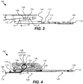
- FIGS. 2 and 3 are, respectively, perspective and side views of the adjustable connector 102.
- the adjustable connector 102 is shown as including a baseplate 110, which is generally planar and includes a front end 112 and back end 116, and a central portion 114 between the front and back ends 112, 116.
- a tongue 120 is located at the front end of the baseplate 110.
- the tongue 120 includes a tongue aperture 122 and is adapted to be received and locked in a buckle (not shown).
- the adjustable connector 102 includes a webbing aperture 130 within the central portion 114 of the baseplate 110.
- the webbing aperture 130 has a front edge 132, a back edge 136, and side edges 139, 140, which collectively define a boundary of the webbing aperture 130.
- a pair of walls 142, 144 extend perpendicularly upward from the baseplate 110 at opposing sides of the baseplate 110. More specifically, the wall 142 extends from the baseplate 110 in close proximity to the side edge 139 of the webbing aperture 130, and the wall 144 extends from the baseplate 110 in close proximity to the side edge 140 of the webbing aperture 130. As shown in FIGS. 2-3 , slots 152, 154 are included respectively within the walls 142, 144. As shown in FIG. 3 , each of the slots 152, 154 is shown as slanting downward towards the back end 116 of the baseplate 110 at an angle ⁇ , which can be referred to as the slot slant angle.
- the slot slant angle ⁇ is within the range of 4 degrees to 15 degrees, and in a specific embodiment is 6 degrees.
- the slots 152, 154 can be generally parallel to the baseplate 110.
- the slot 154 is shown as having a length L and a width w, which are the same respectively as the length and width of the other slot 152. In the embodiment shown in FIG.
- the slots 152, 154 are linear along their entire lengths L, and a radius R at a back end of each of the slots 152, 154 (the end closest to the back end 116 of the baseplate 110) is the same as a radius R at a front end of the slots 152, 154 (the end closest to the front edge 132 of the webbing aperture 130).
- the radius R is in the range of 1.5 millimeters (mm) to 2.5mm, and in a specific embodiment is 1.75mm.
- the length L of the slots 152, 154 (from the center-to-center of the two circles corresponding to the two radiuses R) is within the range of 7.5mm to 15mm, and in a specific embodiment is 10mm.
- the slots 152, 154 are not linear along their entire lengths L, but rather, the lengths of the slots 152, 154 can be partially or continuously curved, or can be made up of multiple contiguous linear segments each having a different slant angle, or made up of a combination of one or more linear segments and one or more curved segments.
- each of the slots is tapered, such that the slots are narrower in width at the back ends of the slots (closest to the back end 116 of the baseplate 110) than at the front ends of the slots (closest to the front edge 132 of the webbing aperture 130).
- the lengths L of the two slots 152, 154 are the same, such lengths can also be referred to singularly as a length (or the length) of the slots.
- the tongue 120 and the walls 142, 144 are integrally formed with the baseplate 110.
- the baseplate 110, the tongue 120, and the walls 142, 144 are made from a blank of cold rolled carbon steel that is chrome nickel plated and bent to provide the walls 142, 144.
- a blank could already include the apertures 122 and 130, and the slots 152 and 154 before portions of the blank are bent to provide the walls 142, 144.
- Metalworking machines that can be used to bend such a blank are often referred to as brakes, bending machines, bending breaks, sheet metal folders, or folders.
- the use of alternative types of metals or alloys and coatings are also within the scope of the embodiments described herein.
- the adjustable connector 102 also includes a rotatable lock bar 160 that is configured to span a gap between the walls 142, 144.
- the rotatable lock bar 160 include a central portion 162 having an outer surface 164.
- the outer surface 164 is preferably textured (e.g., knurled) to increase the coefficient of friction of the outer surface 164 compared to if it were smooth, so that the outer surface 164 will readily grip a length of webbing.
- Tabs 166, 168 extend from opposing longitudinal ends of the central portion 162 and have smaller diameters (or more generally, cross-sectional widths) than the central portion 162.
- the diameters (or more generally, cross-sectional widths) of the tabs 166, 168 are slightly smaller than widths of the slots 152, 154, thereby enabling the tabs 166, 168 to rest within, be slidable along, and be rotatable within, the entire lengths of the slots 152, 154.
- the width of the each of the slots 152, 154 can be 3.5mm
- the diameter of each of the tabs 166, 168 can be 3.0mm.
- the rotatable lock bar 160 is made from heat treated carbon steel that is zinc plated. The use of other types of metals or alloys and/or coatings for the rotatable lock bar 160 are also within the scope of the embodiments described herein.
- FIG. 4 is a cross-sectional view of the adjustable connector 102 taken along the line 4-4 in FIG. 2 , viewed in the direction of the arrows, and showing a loop of webbing 172 extending around the rotatable lock bar 160 of the adjustable connector 102.
- the loop of webbing 172 includes an upper free end segment 173 and a lower connected end segment 174 that is connected to something sturdy, such as a frame of a stretcher, cot, wheelchair, seat, or vehicle, but not limited thereto.
- a portion of the free end segment 173 of the loop of webbing 172 comes into contact with the back edge 136 of the webbing aperture 130 when a force is applied to the free end segment 173 in the direction of the arrow 190 shown in FIG. 4 , as explained in further detail below.
- the webbing 172 is a fabric material coated or encapsulated by a plastic, such as urethane, in which case the webbing 172 can be referred to as a coated webbing 172, or even more specifically (if coated by urethane) as a urethane coated webbing 172.
- a urethane coated webbing can be coated, e.g., with thermoplastic polyurethane (TPU) that is specifically designed to be resistant to oil, grease and abrasion.
- TPU thermoplastic polyurethane
- An exemplary urethane coated webbing is the PathoShieldTM webbing available from Masson Inc., headquartered in Indianapolis, Indiana.
- the coated webbing 172 will grip the outer surface 164 (of the central portion 162 of the rotatable lock bar 160) when the webbing 172 comes in contact therewith.
- urethane coated webbing is stiffer and has a higher coefficient of friction compared to conventional non-coated webbing. This makes it very difficult to adjust the location of a conventional adjustable connector (which includes a non-rotatable lock bar) along a urethane coated webbing, as will be described in additional detail below.
- the webbing 172 can be some other type of coated webbing that is resistant to oil, grease (and liquids in general), and is thereby easily cleanable. Such a coated webbing is also preferably resistant to abrasion.
- the webbing 172 can alternatively be a non-coated more conventional type of webbing.
- the central portion 162 of the rotatable lock bar 160 is cylindrical and has a circular cross-section.
- the tabs 166, 168 of the rotatable lock bar 160 are also cylindrical and have a circular cross-section.
- the central portion 162 of the rotatable lock bar 160 need not be cylindrical and need not have a circular cross-section.
- the central portion 162 of the rotatable lock bar 160 can alternatively be cuboidal or rectangular and have a square or rectangular cross-section.
- the cross-section of the central portion 162 of the rotatable lock bar 160 can have various other shapes, such as, but not limited to, pentagonal, hexagonal, or octagonal.
- the tabs 166, 168 of the rotatable lock bar 160 need not be cylindrical and need not have a circular cross-section, so long as the tabs 166, 168 are slidable along and rotatable within an entire lengths of the slots 152, 154, to thereby enable the rotatable lock bar 160 to be slidable along and rotatable in both clockwise and counter-clockwise directions along the entire lengths of the slots 152, 154.
- the cross-sections of the tabs 166, 168 of the rotatable lock bar 160 can have various other shapes, such as, but not limited to, pentagonal, hexagonal, or octagonal.
- the tabs are oval, which provides certain advantages explained below with reference to FIGS. 6-8 .
- an end of the segment 174 of the webbing is secured to something sturdy, as noted above.
- a most distal end of the free end segment 173 of the webbing 172 is extended beneath the baseplate 110 and upwardly through the webbing aperture 130 in a counterclockwise direction (as viewed in FIG. 4 ) and at least partially around the rotatable lock bar 160 passing back through the webbing aperture 130 near the back edge 136.
- a length of the webbing 172 is looped around the central portion 162 of the rotatable lock bar 160. While the free end segment 173 of the webbing 172 is positioned over a main body of the webbing 172, a user can grasp and pull the free end segment 173 into the direction of arrow 190 to tighten the adjustable connector 102.
- the tongue 120 is lockingly engageable with a buckle (not shown) that is secured directly or via another length of webbing to a vehicle, bed, chair, cot, stretcher frame, or the like.
- a user grasps the free end segment 173 of the webbing 172 and pulls it in the direction of the arrow 190.
- the rotatable lock bar 160 rotates in a counterclockwise direction as viewed in FIG. 4 .
- the webbing 172 is gripped by the outer surface 164 of the central portion 162 of the rotatable lock bar 160 which will cause the rotatable lock bar 160 to move (e.g., downwardly) in slots 152, 154 causing the webbing to serpentine around the back edge 136 of the webbing aperture 130 thereby positioning a portion of the webbing 172 adjacent to and against the back edge 136, and thereby locking the webbing 172 to the adjustable connector 102, and vice versa.
- the rotatable lock bar 160 is able to rotate as the adjustable connector 102 is moved to-and-fro relative to the webbing 172.
- the rotatability of the rotatable lock bar 160 provides a mechanism by which a location of the adjustable connector 102 can be adjusted relative to the length of the webbing 172 when the webbing 172 is slack and positioned apart from the back edge 136 of the webbing aperture 130.
- the rotatable lock bar 160 allows contact between the webbing 172 and the rotatable lock bar 160 to limit relative motion between the webbing 172 and the rotatable lock bar 160 as the rotatable lock bar 160 moves (e.g., downwardly) in the slots 152, 156 and forces a portion of the webbing 172 against the back edge 136 of the webbing aperture.
- the back edge 136 of the webbing aperture 130 provides a stop surface which extends perpendicularly to and between the upstanding walls 142, 144.
- the back edge 136 of the webbing aperture 130 engages a portion of the webbing 172 when the webbing 172 is taut and extending in the direction of arrow 190 which is parallel and in an opposite direction to the direction that the tongue 120 extends from baseplate 110.
- the adjustable connector 102 may be grasped and pulled upwardly until the webbing is generally perpendicularly arranged relative to the baseplate 110. Such grasping of the adjustable connector 102 can be achieved, e.g., by a user placing one or more of their fingertips under the back end 116 of the baseplate 110.
- the front edge of the webbing aperture of a conventional adjustable connector spans generally straight across a baseplate between the side edges of the webbing aperture, such that substantially the entire front and back edges of the webbing aperture are parallel to one another.
- the front edge 132 of the webbing aperture 130 within the baseplate 110 is arced. More specifically, in the embodiment shown in FIGS. 1-4 the front edge 132 of the webbing aperture 130 is arced as it extends between the side edges 139, 140 of the webbing aperture 130 such that a distance ( d1 in FIG.
- the distance ( d1 in FIG. 1 ) between the center of the arced front edge 132 and the back edge 136 of the webbing aperture 130 is at least 50% greater than the distance ( d2 in FIG. 1 ) between each of the ends 137, 138 of the arced front edge 132 and the back edge 136 of the webbing aperture 130.
- the arced front edge 132 of the webbing aperture 130 includes an intermediate arced portion 133 and distal arced portions 134, 135, wherein the intermediate arced portion 133 extends between the distal arced portion 134 and the distal arced portion 135.
- the intermediate arced portion 133 has an arc radius ( r1 in FIG. 1 ) that is greater than the arc radius ( r2 in FIG. 1 ) of each of the distal arced portions 134, 134 of the arced front edge 132 of the webbing aperture 130.
- the arc radius r1 of the intermediate arced portion 133 is at least three times greater (i.e., at least 3X) than the arc radius r2 of each of the distal arced portions 134, 135.
- the arc radius r1 of the intermediate arced portion 133 is about 60 mm (i.e., about 2.4 inches)
- the arc radius r2 of each of the distal arced portions 134, 135 is about 13 mm (i.e., about 0.5 inches).
- the term "about”, as used herein, means within plus or minus 10 percent (i.e., +/- 10%) of a specified value.
- the rotatable lock bar 160 (which includes the central portion 162 and the tabs 166, 168 extending from opposing longitudinal ends of the central portion 162) significantly improves the adjustability of the adjustable connector 102, compared to if the adjustable connector 102 included a conventional non-rotatable lock bar, while still enabling the adjustable connector 102 to pass applicable federal and industry safety standards, such as Standard No. 209 of the Federal Motor Vehicle Safety Standards (FMVSS) covering seatbelt assemblies, and the J3027 Recommended Practices related to "Ambulance Litter Integrity, Retention and Patient Restraint" by the Society of Automotive Engineers (SAE).
- FMVSS Federal Motor Vehicle Safety Standards
- SAE Society of Automotive Engineers
- the arced front edge 132 of the webbing aperture 130 also significantly improves the adjustability of the adjustable connector 102, compared to if the front edge of the webbing aperture conventionally spanned generally straight across the baseplate between the side edges of the webbing aperture, while still enabling the adjustable connector 102 to pass applicable federal and industry safety standards, such as Standard No. 209 of the FMVSS, and SAE Recommendation J3027, which were mentioned above.
- the lock bar is non-rotatable, and the front edge of the webbing aperture spans generally straight across the baseplate between the side edges of the webbing aperture.
- Tests have shown that by including both the rotatable lock bar 160 and the arced front edge 132 of the webbing aperture 130, the adjustability of the adjustable connector 102 along a length of urethane coated webbing 172 is increased by about 60% compared to such a conventional adjustable connector, while still satisfying applicable safety standards.
- Such tests were performed by measuring how much force is required to move the adjustable connector relative to the urethane coated webbing 172 when a portion of the webbing was not forced against the back edge 136 of the webbing aperture (in multiple orientations ranging from horizontal to vertical).
- the adjustability is still improved by about 20% compared to use of the convention non-rotatable rectangular lock bar with urethane coated webbing, while still satisfying applicable safety standards.
- a baseplate including the arced front edge 132 of the webbing aperture 130 together with a convention non-rotatable rectangular lock bar with urethane coated webbing the adjustability is still improved by about 40% compared to if the webbing aperture had a conventional front edge (that spans generally straight across the baseplate between the side edges of the webbing aperture), while still satisfying applicable safety standards.
- an adjustable connector e.g., 102, 102'
- an adjustable connector that includes both of the aforementioned improvements (i.e., both a rotatable cylindrical locking bar, e.g., 160, and an arced front edge, e.g., 132, of a webbing aperture in a baseplate)
- improvements in adjustability relative to a urethane coated webbing can also be achieved by providing just one of these two features, and certain embodiments of the present technology are also related to adjustable connectors that include just one of the two improvements.
- the arced front edge 132 of the webbing aperture 130 is shown as being continuously curved such that it is devoid of any linear segments.
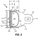
- an arced front edge 132' of a webbing aperture 130' is shown as being a piecewise linear curve including a plurality of linear segments that collectively form the arced front edge 132' similar to the continuously curved arced front edge 132 best shown in FIG. 1 .
- the remaining components of the adjustable connector 102' which are the same as in the adjustable connector 102, are labeled the same and need not be described again.
- Another benefit of having the front edge (e.g., 132 or 132') of the webbing aperture (e.g., 130 or 130') of a baseplate (e.g., 110) be arced, rather than span straight across between sides of the webbing aperture, is that is reduces the friction between the front edge and the webbing, thereby improving the reliability of the combination of the adjustable connector (e.g., 102 and 102') and the webbing 172, especially where the webbing 172 is a urethane coated webbing, or some other type of coated webbing.
- the webbing constantly rubs against the front edge of the webbing aperture in a manner that can eventually rub off the coating and abrade the underlying webbing material such that it may eventually fail.
- rubbing of the webbing against the front edge of the webbing aperture is significantly reduced such that the coating does not rub off and the underlying webbing material does not abrade such that it may eventually fail.
- FIGS. 6-8 An alternative embodiment of the adjustable connector, labeled 102", is shown in and described with reference to FIGS. 6-8 .
- Elements of the adjustable connector 102" that are the same those elements of the adjustable connector 102 described above (with reference to FIGS. 1-4 ) are labeled the same, and need not be described again.
- Differences between the adjustable connector 102" and the adjustable connector 102 relates to the slots in the walls that extend perpendicularly upward from the baseplate 110, and the shape of the tabs of the rotatable lock bar that spans the gap between the walls 142, 144.
- a slot 154" in the wall 144 is shown as being tapered such that the slot 154" is narrower its back end (closest to the back end 116 of the baseplate 110) than at its front end (closest to the front edge 132 of the webbing aperture 130). While not specifically shown in FIG. 6 , a corresponding slot 152" in the other wall 142 is similarly tapered such that the slot 152" is narrower its back end (closest to the back end 116 of the baseplate 110) than at its front end (closest to the front edge 132 of the webbing aperture 130).
- the radius R2 of the back end of the slots 152", 154" is smaller than the radius R1 of the front ends of the slots 152", 154".
- the radius R2 of the back end of the slots 152", 154" is at least 10% smaller than the radius R1 of the front ends of the slots 152", 154".
- the radius R2 is 1.75mm and the radius R1 is 2.0mm.
- a tab 168" is shown as extending from a longitudinal end of a rotatable lock bar 160", wherein the tab 168" is oval, rather than circular, as was the case in the previous embodiments described above. While not specifically shown in FIG. 6 , a corresponding oval tab 166" extends from the other longitudinal end of the rotatable lock bar 160". To provide for their oval shape, a first diameter D1 of the tab 168" (and the tab 166") in a first radial direction is greater than a second diameter D2 of the tab 168" (and the tab 166") in a second radial direction that is orthogonal to the first radial direction.
- the diameter D1 of the tab 168" (and the tab 166") in the first radial direction is at least 10% greater than the diameter D2 of the tab 168" (and the tab 166") in the second radial direction that is orthogonal to the first radial direction.
- the diameter D1 of the tab 168" (and the tab 166") in the first radial direction is 3.6mm and the diameter D2 of the tab 168" (and the tab 166") in the second radial direction that is orthogonal to the first radial direction is 3.0mm.
- the diameter D1 can also be referred to as the major-axis, and the diameter D2 can also be referred to as the minor-axis. In FIG.
- oval tab 168" is shown as being elliptical, which means it is symmetrical along both its major and minor-axis. This would also be the case for the other oval tab 166", which is a mirror image of the oval tab 168".
- the oval tabs 166",168" need not be elliptical. Rather, the oval tabs can instead have an ovoidal (aka “egg shaped”) circumference or perimeter such that they are only symmetrical along their major-axis.
- the rotatable lock bar 160" also includes a central portion 162 having an outer surface 164 that is preferably textured (e.g., knurled) to increase the coefficient of friction of the outer surface 164 compared to if it were smooth, so that the outer surface 164 will readily grip a length of webbing.
- the oval tabs 166", 168" extend from opposing longitudinal ends of the central portion 162 of the rotatable lock bar 160" and have smaller diameters (or more generally, cross-sectional widths) than the central portion 162.
- the larger diameter D1 of the oval tabs 166", 168" is slightly larger than the narrowest width of the slots 152", 154" (i.e., is slightly larger than twice the radius R2 ).
- the radius R2 is 1.75mm
- the radius R1 is 2.0mm
- the diameter D1 is 3.6mm
- the diameter D2 is 3.0mm.
- the width or diameter of the slots 152", 154" is 3.5mm (i.e., twice the radius R2 ).
- the width or diameter of the slots 152", 154" is 4.0mm (i.e., twice the radius R1 ).
- the larger diameter D1 of the oval tabs 166", 168" is 3.6mm, that is slightly larger than the 3.5mm narrowest width of the slots 152", 154" proximate the back ends of the sots 152", 154".
- the tabs 166", 168" will eventually stop rotating because the diameter D1 (e.g., 3.6mm, aka the major-axis) of the tabs 166", 168" is larger than the width of the tapered slots 152", 154" (e.g., 3.5mm, which is twice 1.75mm radius R2 ) at their back ends (closest to the back end 116 of the baseplate 110).
- D1 e.g., 3.6mm, aka the major-axis
- the width of the tapered slots 152", 154" e.g., 3.5mm, which is twice 1.75mm radius R2
- Such an arrangement enables a person to relatively easily move the adjustable connector 102" along a length of the urethane coated webbing, while ensuring that under heavy loads (e.g., due to an emergency vehicle, or the like, stopping short) the adjustable connector 102" will lock in place thereby securely holding in place whomever or whatever the adjustable connector 102" and urethane coated webbing (or some other type of coated or non-coated webbing) are being used to secure.
- the rotatable lock bar 160" will rotate for adjustments, but under heavy loads the small minor-axis of the cross-section of the tabs 166", 168” will rotate into the smaller radius at back ends of the tapered slots 152", 154" and be unable to rotate in a high load locking position as the larger major-axis of the cross-sections of the tabs 166", 168" is slightly bigger than the diameter of the tapered slots 152", 154" at the back ends of the tapered slots 152", 154".
- any attempt to rotate at the back ends of the tapered slots 152", 154" will make the bar 160 lock into the tapered slots 152", 154" and not rotate.
- FIG. 7 is a cross-sectional view of the adjustable connector 102" (similar to the cross-sectional view in FIG. 4 ) and showing a loop of webbing 172 extending around the rotatable lock bar 160" of the adjustable connector 102".
- the loop of webbing 172 includes an upper free end segment 173 and a lower connected end segment 174 that is connected to something sturdy, such as a frame of a stretcher, cot, wheelchair, seat, or vehicle, but not limited thereto.
- a portion of the free end segment 173 of the loop of webbing 172 comes into contact with the back edge 136 of the webbing aperture 130 when a force is applied to the free end segment 173 in the direction of the arrow 190 shown in FIG. 7 .
- Exemplary details of the webbing 172 were discussed above with reference to FIG. 4 , and thus, need not be repeated.
- the central portion 162" of the rotatable lock bar 160" is cylindrical and has a circular cross-section.
- the tabs 166", 168" of the rotatable lock bar 160" instead of having a circular cross-section (as was the case in FIG. 4 ), have an oval cross-section, as was explained above with reference to FIG. 6 .
- the central portion 162" of the rotatable lock bar 160" can have a square, rectangular, pentagonal, hexagonal, or octagonal cross-section, but not limited thereto.
- the circumference or periphery of the cross-section of the oval tabs 166", 168" of the rotatable lock bar 160" need not be made up of a continuous curve so long as the tabs 166", 168" are slidable along the entire length of the tapered slots 152", 154" and rotatable in both clockwise and counter-clockwise directions within a majority of (and preferably at least 80%) of the length of the tapered slots 152", 154", and are prevented from rotating when in close proximity to the back end of the tapered slots 152", 154".
- FIGS. 8A, 8B, and 8C Example alternative cross sections for the tabs are shown in FIGS. 8A, 8B, and 8C , which can be collectively referred to as FIG. 8 .
- the major-axis of the cross-sections are labeled D1 and the minor-axis of the cross-sections are labeled D2, wherein D2 is greater than D1, and D2 is preferably at least 10% greater than D1.
- the adjustable connector 102" operates in a similar manner as the adjustable connector 102 (shown in FIG. 4 ), except that the adjustable connector 102" can be locked in place in a more secure manner and withstand greater forces, due to the inclusion of the tapered slots 152", 154" and the oval tabs 166", 168" (or alternatively shaped tabs that have a cross-section with a major-axis that is greater than the minor-axis, e.g., as shown in FIG. 8 ).
- the front edge of its webbing aperture 130 can be like the front edge 132 shown in FIG. 1 , or like the front edge 132' shown in FIG. 5 , depending upon the specific implementation.
- adjustable connectors e.g., 102, 102', 102
- the adjustable connectors can also be attached to conventional non-coated webbing.
- the adjustable connectors (e.g., 102, 102', 102") of the embodiments of the present technology can also include a plastic cover that snaps over a baseplate (e.g., 110) such that the lock bar (e.g., 160) and the webbing aperture (e.g., 130, 130') cannot be seen when viewing the adjustable connectors from the top.
- a baseplate e.g., 110
- the lock bar e.g., 160
- the webbing aperture e.g., 130, 130'
- a connection may be a direct connection or an indirect connection (e.g., via one or more other parts).
- the element when an element is referred to as being connected or coupled to another element, the element may be directly connected to the other element or indirectly connected to the other element via intervening elements.
- the element When an element is referred to as being directly connected to another element, then there are no intervening elements between the element and the other element.
Landscapes
- Engineering & Computer Science (AREA)
- Mechanical Engineering (AREA)
- Automotive Seat Belt Assembly (AREA)
Abstract
Description
- Embodiments of the present technology generally relate to adjustable connectors for use with patient harness systems and other types of safety belt systems.
- Patient transport apparatuses are used to transport patients in ambulances, other types of vehicles, hospitals, and other types of facilities. Various types of patient transport apparatuses exist, such as, but not limited to, stretchers, cots, wheelchairs, hospital beds, and/or the like. When used to transport patients, e.g., in an ambulance or hospital, it is important to keep the patients securely restrained for their safety and the safety of the medical personnel transporting the patients. Accordingly, harness systems are often used to restrain patients to patient transport apparatuses. Harness systems may also be used to restrain medical personnel to their seats within ambulances and other emergency vehicles. Such harness systems should preferably be easily adjustable so that they readily accommodate use with patients and medical personnel of different sizes, e.g., different heights, weights and girths. Adjustable connectors, which include a metal or alloy tongue (adapted to be received and locked in a buckle) and a metal or alloy lock bar (adapted to lock the connector in place) are typically used to allow for such adjustability. Additionally, such harness systems should be sufficiently strong and lockable to withstand certain crash events. More specifically, they may also need to meet applicable safety standards, such as, but not limited to, crash safety standards if used in vehicles. Further, since such harness systems may be used with patients that are ill, bleeding, vomiting, and/or leaking other bodily fluids, such harness systems are preferably easily cleanable.
- Conventional harness systems have used nylon or polyester webbing to strap patients to patient transport apparatuses. However, such webbing if typically porous and thus difficult to clean once subjected to bodily fluids, dirt, grease, and/or other contami nants.
- Recently, coated webbings have been manufactured and sold that are liquid resistant and easy to clean. An example of such a coated webbing is the PathoShield™ urethane coated webbing available from Masson Inc., headquartered in Indianapolis, Indiana.
- A problem with using urethane coated webbing in harness systems is that such webbing is much stiffer than conventional webbing and has a much greater coefficient of friction than conventional webbing, making urethane coated webbing much more difficult to use with adjustable connectors that are made of metal or alloy. More specifically, tests have shown that it is very difficult to adjust the location of an adjustable connector (made of metal or alloy) along a length of urethane coated webbing. Accordingly, while urethane coated webbing has been available for quite some time, many manufacturers of patient transport apparatuses and/or harness systems have not yet incorporated urethane coated webbing into their products. Accordingly, quite a bit of time and other resources are still typically required to clean the webbing that is used in harness systems of patient transport apparatuses.
- Certain embodiments of present technology are directed to an adjustable connector adapted to connect webbing (e.g., a urethane coated webbing) to a buckle. The adjustable connector includes a baseplate, a tongue, a webbing aperture, and a rotatable lock bar. The baseplate is generally planar and includes a front end, a back end, and a central portion between the front and back ends. The tongue, which is at the front end of the baseplate, is adapted to be received and locked in a buckle. The webbing aperture, which is within the central portion of the baseplate, includes a front edge, a back edge, and first and second side edges. Further, first and second walls extend perpendicularly from the baseplate, with first and second slots respectively within the first and second walls. In certain embodiments, the first and second slots each slope downwards towards the back end of the baseplate.
- In accordance with certain embodiments, the rotatable lock bar includes a central portion having an outer surface that is preferably textured (e.g., knurled). First and second tabs extend from opposing longitudinal ends of the central portion. The first and second tabs rest respectively within the first and second slots. In certain embodiments, the first and second tabs are slidable along a length of the first and second slots and rotatable within at least a majority of the length of the first and second slots, to thereby enable the rotatable lock bar to be slidable along the length of the first and second slots and rotatable in both clockwise and counterclockwise directions within at least the majority of the length of the first and second slots.
- In accordance with certain embodiments, the adjustable connector is adapted for use with a coated webbing having a length thereof that is received within the webbing aperture and loops around at least 180 degrees of the outer surface of the rotatable lock bar. The coated webbing can, e.g., a urethane coated webbing, or some other type of liquid resistant and easily cleanable coated webbing. The rotatable lock bar is adapted to lock the adjustable connector in place relative to the coated webbing, in response to a force being applied to the webbing in a direction that is generally opposite the tongue and generally parallel to the baseplate such that a portion of the webbing adjacent to the back edge of the webbing aperture is forced against the back edge of the webbing aperture. Additionally, the rotatable lock bar is adapted to rotate and allow the adjustable connector to be moved relative to the coated webbing, in response to a force being applied to the webbing in a direction that is generally perpendicular to the baseplate such that the portion of the webbing adjacent to the back edge of the webbing aperture is not forced against the back edge of the webbing aperture.
- In accordance with certain embodiments, the front edge of the webbing aperture comprises an arced front edge that extends between the first and second side edges of the webbing aperture such that a distance between a center of the arced front edge of the webbing aperture and the back edge of the webbing aperture is greater than a respective distance between each of the ends of the arced front edge and the back edge of the webbing aperture. The arced front edge of the webbing aperture provides for increased adjustability of the adjustable connector relative to the coated webbing, in response to a force being applied to the webbing in a direction that is generally perpendicular to the baseplate such that the portion of the webbing adjacent to the back edge of the webbing aperture is not forced against the back edge of the webbing aperture, compared to if the front edge of the webbing aperture was a straight edge extending perpendicularly between the first and second side edges of the webbing aperture.
- In accordance with certain embodiments, the front edge of the webbing aperture comprises an arced front edge that extends between the first and second side edges of the webbing aperture such that a distance between a center of the arced front edge of the webbing aperture and the back edge of the webbing aperture is greater than a respective distance between each of the ends of the arced front edge and the back edge of the webbing aperture. In certain embodiments, the distance between the center of the arced front edge of the webbing aperture and the back edge of the webbing aperture is at least 50% greater than the respective distance between each of the ends of the arced front edge and the back edge of the webbing aperture.
- In accordance with certain embodiments, the arced front edge of the webbing aperture includes an intermediate arced portion that extends between first and second distal arced portions, wherein the intermediate arced portion of the arced front edge of the webbing aperture has an arc radius that is greater than a respective arc radius of each of the first and second distal arced portions of the arced front edge of the webbing aperture. More specifically, in certain embodiments, the arc radius of the intermediate arced portion of the arced front edge of the webbing aperture is at least three times greater than the respective arc radius of each of the first and second distal arced portions of the arced front edge of the webbing aperture.
- Where the front edge of the webbing aperture is an arced front edge, the arced front edge of the webbing aperture provides for increased adjustability of the adjustable connector relative to the coated webbing, in response to a force being applied to the webbing in a direction that is generally perpendicular to the baseplate such that the portion of the webbing adjacent to the back edge of the webbing aperture is not forced against the back edge of the webbing aperture, compared to if the front edge of the webbing aperture was a straight edge extending perpendicularly between the first and second side edges of the webbing aperture.
- In accordance with certain embodiments, the arced front edge of the webbing aperture is devoid of any linear segments. In accordance with other embodiments, the arced front edge of the webbing aperture comprises a piecewise linear curve including at least one linear segment.
- In accordance with certain embodiments, each of the first and second slots comprises a tapered slot having front end and a back end, with a width of the front end of the tapered slot being greater than a width of the back end of the tapered slot. Each of the first and second tabs has a cross-section including a major-axis that is larger than a minor-axis that is orthogonal to the major-axis. The major-axis of each of the first and second tabs is smaller than the width of each of the first and second tabs at the front ends of the first and second slots. The major-axis of each of the first and second tabs is larger than the width of each of the first and second tabs at the back ends of the first and second slots.
- In accordance with certain embodiments, the rotatable lock bar is slidable along and fully rotatable within the first and second tapered slots from the front ends of the first and second tapered slots to at least halfway toward the back ends of the first and second tapered slots. The rotatable lock bar is no longer fully rotatable within the first and second tapered slots when the first and second tabs of the rotatable lock bar are proximate the back ends of the first and second tapered slots, due to the major-axis of each of the first and second tabs being larger than the width of each of the first and second slots at the back ends of the first and second slots. In accordance with certain embodiments, the cross-section of each of the first and second tabs is oval.
- This Summary is provided to introduce a selection of concepts in a simplified form that are further described below in the Detailed Description. This Summary is not intended to identify key features or essential features of the claimed subject matter, nor is it intended to be used as an aid in determining the scope of the claimed subject matter.
-
-
FIG. 1 is a top view of an adjustable connector according to an embodiment of the present technology. -
FIG. 2 is a perspective view of the adjustable connector shown inFIG. 1 . -
FIG. 3 is a side view of the adjustable connector shown inFIGS. 1 and 2 . -
FIG. 4 is a cross-sectional view of the adjustable connector shown inFIGS. 1-3 taken along the line 4-4 inFIG. 2 , viewed in the direction of the arrows, and showing a loop of webbing extending around a rotatable lock bar of the adjustable connector. -
FIG. 5 is a top view of an adjustable connector according to an alternative embodiment of the present technology. -
FIG. 6 is a perspective view of the adjustable connector according to another embodiment of the present technology. -
FIG. 7 is a cross-sectional view of the adjustable connector shown inFIG. 6 , and showing a loop of webbing extending around a rotatable lock bar of the adjustable connector. -
FIGS. 8A, 8B, and 8C , which can be collectively referred to asFIG. 8 , show alternative cross-sections of tabs that extend from longitudinal ends of the rotatable lock bar of the adjustable connector, according to certain embodiments of the present technology. - Certain embodiments of the present technology are directed to adjustable connectors adapted to connect a urethane coated webbing (or some other type of easily cleanable coated webbing) to a buckle. The adjustable connectors described herein can alternatively be used to connect a non-coated webbing to a buckle.
FIG. 1 is a top view of anadjustable connector 102 according to an embodiment of the present technology.FIGS. 2 and3 are, respectively, perspective and side views of theadjustable connector 102. - Referring to
FIGS. 1-3 , theadjustable connector 102 is shown as including abaseplate 110, which is generally planar and includes afront end 112 andback end 116, and acentral portion 114 between the front and back ends 112, 116. Atongue 120 is located at the front end of thebaseplate 110. Thetongue 120 includes atongue aperture 122 and is adapted to be received and locked in a buckle (not shown). - As shown in
FIGS. 1-3 , theadjustable connector 102 includes awebbing aperture 130 within thecentral portion 114 of thebaseplate 110. Thewebbing aperture 130 has afront edge 132, aback edge 136, and side edges 139, 140, which collectively define a boundary of thewebbing aperture 130. - A pair of
walls baseplate 110 at opposing sides of thebaseplate 110. More specifically, thewall 142 extends from thebaseplate 110 in close proximity to theside edge 139 of thewebbing aperture 130, and thewall 144 extends from thebaseplate 110 in close proximity to theside edge 140 of thewebbing aperture 130. As shown inFIGS. 2-3 ,slots walls FIG. 3 , each of theslots back end 116 of thebaseplate 110 at an angle α, which can be referred to as the slot slant angle. In certain embodiments the slot slant angle α is within the range of 4 degrees to 15 degrees, and in a specific embodiment is 6 degrees. In alternative embodiments, rather than sloping downwards, theslots baseplate 110. InFIG. 3 , theslot 154 is shown as having a length L and a width w, which are the same respectively as the length and width of theother slot 152. In the embodiment shown inFIG. 1-3 , theslots slots 152, 154 (the end closest to theback end 116 of the baseplate 110) is the same as a radius R at a front end of theslots 152, 154 (the end closest to thefront edge 132 of the webbing aperture 130). In certain embodiments, the radius R is in the range of 1.5 millimeters (mm) to 2.5mm, and in a specific embodiment is 1.75mm. In certain embodiments, the length L of theslots 152, 154 (from the center-to-center of the two circles corresponding to the two radiuses R) is within the range of 7.5mm to 15mm, and in a specific embodiment is 10mm. In certain alternative embodiments, theslots slots FIGS. 6-8 , each of the slots is tapered, such that the slots are narrower in width at the back ends of the slots (closest to theback end 116 of the baseplate 110) than at the front ends of the slots (closest to thefront edge 132 of the webbing aperture 130). Where the lengths L of the twoslots - Still referring to
FIGS. 1-3 , thetongue 120 and thewalls baseplate 110. In certain embodiments, thebaseplate 110, thetongue 120, and thewalls walls apertures slots walls - The
adjustable connector 102 also includes arotatable lock bar 160 that is configured to span a gap between thewalls rotatable lock bar 160 include acentral portion 162 having anouter surface 164. Theouter surface 164 is preferably textured (e.g., knurled) to increase the coefficient of friction of theouter surface 164 compared to if it were smooth, so that theouter surface 164 will readily grip a length of webbing.Tabs central portion 162 and have smaller diameters (or more generally, cross-sectional widths) than thecentral portion 162. The diameters (or more generally, cross-sectional widths) of thetabs slots tabs slots slots tabs rotatable lock bar 160 to be slidable along the lengths of theslots rotatable lock bar 160 is made from heat treated carbon steel that is zinc plated. The use of other types of metals or alloys and/or coatings for therotatable lock bar 160 are also within the scope of the embodiments described herein. -
FIG. 4 is a cross-sectional view of theadjustable connector 102 taken along the line 4-4 inFIG. 2 , viewed in the direction of the arrows, and showing a loop ofwebbing 172 extending around therotatable lock bar 160 of theadjustable connector 102. The loop ofwebbing 172 includes an upperfree end segment 173 and a lowerconnected end segment 174 that is connected to something sturdy, such as a frame of a stretcher, cot, wheelchair, seat, or vehicle, but not limited thereto. A portion of thefree end segment 173 of the loop ofwebbing 172 comes into contact with theback edge 136 of thewebbing aperture 130 when a force is applied to thefree end segment 173 in the direction of thearrow 190 shown inFIG. 4 , as explained in further detail below. - In accordance with certain embodiments, the
webbing 172 is a fabric material coated or encapsulated by a plastic, such as urethane, in which case thewebbing 172 can be referred to as acoated webbing 172, or even more specifically (if coated by urethane) as a urethane coatedwebbing 172. Such a urethane coated webbing can be coated, e.g., with thermoplastic polyurethane (TPU) that is specifically designed to be resistant to oil, grease and abrasion. An exemplary urethane coated webbing is the PathoShield™ webbing available from Masson Inc., headquartered in Indianapolis, Indiana. Thecoated webbing 172 will grip the outer surface 164 (of thecentral portion 162 of the rotatable lock bar 160) when thewebbing 172 comes in contact therewith. As noted above, urethane coated webbing is stiffer and has a higher coefficient of friction compared to conventional non-coated webbing. This makes it very difficult to adjust the location of a conventional adjustable connector (which includes a non-rotatable lock bar) along a urethane coated webbing, as will be described in additional detail below. Instead of being a urethane coated webbing, thewebbing 172 can be some other type of coated webbing that is resistant to oil, grease (and liquids in general), and is thereby easily cleanable. Such a coated webbing is also preferably resistant to abrasion. Thewebbing 172 can alternatively be a non-coated more conventional type of webbing. - In the embodiment shown in
FIGS. 1-4 , thecentral portion 162 of therotatable lock bar 160 is cylindrical and has a circular cross-section. Similarly, in the embodiment shown inFIGS. 1-4 , thetabs rotatable lock bar 160 are also cylindrical and have a circular cross-section. In alternative embodiments, thecentral portion 162 of therotatable lock bar 160 need not be cylindrical and need not have a circular cross-section. For example, thecentral portion 162 of therotatable lock bar 160 can alternatively be cuboidal or rectangular and have a square or rectangular cross-section. For another example, the cross-section of thecentral portion 162 of therotatable lock bar 160 can have various other shapes, such as, but not limited to, pentagonal, hexagonal, or octagonal. Further, thetabs rotatable lock bar 160 need not be cylindrical and need not have a circular cross-section, so long as thetabs slots rotatable lock bar 160 to be slidable along and rotatable in both clockwise and counter-clockwise directions along the entire lengths of theslots tabs rotatable lock bar 160 can have various other shapes, such as, but not limited to, pentagonal, hexagonal, or octagonal. In other embodiments, described below with reference toFIGS. 6-8 , the tabs are oval, which provides certain advantages explained below with reference toFIGS. 6-8 . - Referring to
FIG. 4 , in certain embodiments, an end of thesegment 174 of the webbing is secured to something sturdy, as noted above. In order to connect theadjustable connector 102 to thewebbing 172, a most distal end of thefree end segment 173 of thewebbing 172 is extended beneath thebaseplate 110 and upwardly through thewebbing aperture 130 in a counterclockwise direction (as viewed inFIG. 4 ) and at least partially around therotatable lock bar 160 passing back through thewebbing aperture 130 near theback edge 136. In other words, to connect theadjustable connector 102 to thewebbing 172, a length of thewebbing 172 is looped around thecentral portion 162 of therotatable lock bar 160. While thefree end segment 173 of thewebbing 172 is positioned over a main body of thewebbing 172, a user can grasp and pull thefree end segment 173 into the direction ofarrow 190 to tighten theadjustable connector 102. - In operation, the
tongue 120 is lockingly engageable with a buckle (not shown) that is secured directly or via another length of webbing to a vehicle, bed, chair, cot, stretcher frame, or the like. A user grasps thefree end segment 173 of thewebbing 172 and pulls it in the direction of thearrow 190. In the event slack exists in thewebbing 172 therotatable lock bar 160 rotates in a counterclockwise direction as viewed inFIG. 4 . As thewebbing 172 is further tightened, thewebbing 172 is gripped by theouter surface 164 of thecentral portion 162 of therotatable lock bar 160 which will cause therotatable lock bar 160 to move (e.g., downwardly) inslots back edge 136 of thewebbing aperture 130 thereby positioning a portion of thewebbing 172 adjacent to and against theback edge 136, and thereby locking thewebbing 172 to theadjustable connector 102, and vice versa. - The
rotatable lock bar 160 is able to rotate as theadjustable connector 102 is moved to-and-fro relative to thewebbing 172. The rotatability of therotatable lock bar 160 provides a mechanism by which a location of theadjustable connector 102 can be adjusted relative to the length of thewebbing 172 when thewebbing 172 is slack and positioned apart from theback edge 136 of thewebbing aperture 130. Additionally, by being slidable along the lengths of theslots rotatable lock bar 160 allows contact between thewebbing 172 and therotatable lock bar 160 to limit relative motion between thewebbing 172 and therotatable lock bar 160 as therotatable lock bar 160 moves (e.g., downwardly) in theslots 152, 156 and forces a portion of thewebbing 172 against theback edge 136 of the webbing aperture. - The
back edge 136 of thewebbing aperture 130 provides a stop surface which extends perpendicularly to and between theupstanding walls back edge 136 of thewebbing aperture 130 engages a portion of thewebbing 172 when thewebbing 172 is taut and extending in the direction ofarrow 190 which is parallel and in an opposite direction to the direction that thetongue 120 extends frombaseplate 110. By positioning thewebbing 172 generally perpendicular tobaseplate 110, the portion of thewebbing 172 that had been forced against theback edge 136 is moved apart from theback edge 136 thereby unlocking theadjustable connector 102 from thewebbing 172 and again allowing therotatable lock bar 160 to rotate, and thereby, again allowing movement and adjustment of the location of theadjustable connector 102 along a length of thewebbing 172. Thus, in order unlock thewebbing 172 from theadjustable connector 102, and vice versa, theadjustable connector 102 may be grasped and pulled upwardly until the webbing is generally perpendicularly arranged relative to thebaseplate 110. Such grasping of theadjustable connector 102 can be achieved, e.g., by a user placing one or more of their fingertips under theback end 116 of thebaseplate 110. - The front edge of the webbing aperture of a conventional adjustable connector spans generally straight across a baseplate between the side edges of the webbing aperture, such that substantially the entire front and back edges of the webbing aperture are parallel to one another. By contrast, in the embodiment shown in
FIGS. 1-4 , and best seen inFIGS. 1 and 2 , thefront edge 132 of thewebbing aperture 130 within thebaseplate 110 is arced. More specifically, in the embodiment shown inFIGS. 1-4 thefront edge 132 of thewebbing aperture 130 is arced as it extends between the side edges 139, 140 of thewebbing aperture 130 such that a distance (d1 inFIG. 1 ) between a center of the arcedfront edge 132 and theback edge 136 of thewebbing aperture 130 is greater than a distance (d2 inFIG. 1 ) between each of theends front edge 132 and theback edge 136 of thewebbing aperture 130. Preferably, the distance (d1 inFIG. 1 ) between the center of the arcedfront edge 132 and theback edge 136 of thewebbing aperture 130 is at least 50% greater than the distance (d2 inFIG. 1 ) between each of theends front edge 132 and theback edge 136 of thewebbing aperture 130. - Referring to
FIG. 1 , in the embodiment shown, the arcedfront edge 132 of thewebbing aperture 130 includes an intermediate arcedportion 133 and distal arcedportions portion 133 extends between the distal arcedportion 134 and the distal arcedportion 135. The intermediate arcedportion 133 has an arc radius (r1 inFIG. 1 ) that is greater than the arc radius (r2 inFIG. 1 ) of each of the distal arcedportions front edge 132 of thewebbing aperture 130. In certain embodiments, the arc radius r1 of the intermediate arcedportion 133 is at least three times greater (i.e., at least 3X) than the arc radius r2 of each of the distal arcedportions portion 133 is about 60 mm (i.e., about 2.4 inches), and the arc radius r2 of each of the distal arcedportions - The rotatable lock bar 160 (which includes the
central portion 162 and thetabs adjustable connector 102, compared to if theadjustable connector 102 included a conventional non-rotatable lock bar, while still enabling theadjustable connector 102 to pass applicable federal and industry safety standards, such as Standard No. 209 of the Federal Motor Vehicle Safety Standards (FMVSS) covering seatbelt assemblies, and the J3027 Recommended Practices related to "Ambulance Litter Integrity, Retention and Patient Restraint" by the Society of Automotive Engineers (SAE). Further, the arcedfront edge 132 of thewebbing aperture 130 also significantly improves the adjustability of theadjustable connector 102, compared to if the front edge of the webbing aperture conventionally spanned generally straight across the baseplate between the side edges of the webbing aperture, while still enabling theadjustable connector 102 to pass applicable federal and industry safety standards, such as Standard No. 209 of the FMVSS, and SAE Recommendation J3027, which were mentioned above. - As noted above, in a conventional adjustable connector, the lock bar is non-rotatable, and the front edge of the webbing aperture spans generally straight across the baseplate between the side edges of the webbing aperture. Tests have shown that by including both the
rotatable lock bar 160 and the arcedfront edge 132 of thewebbing aperture 130, the adjustability of theadjustable connector 102 along a length of urethane coatedwebbing 172 is increased by about 60% compared to such a conventional adjustable connector, while still satisfying applicable safety standards. Such tests were performed by measuring how much force is required to move the adjustable connector relative to the urethane coatedwebbing 172 when a portion of the webbing was not forced against theback edge 136 of the webbing aperture (in multiple orientations ranging from horizontal to vertical). By using therotatable lock bar 160 together with a baseplate having a webbing aperture including a conventional front edge (that spans generally straight across the baseplate between the side edges of the webbing aperture), the adjustability is still improved by about 20% compared to use of the convention non-rotatable rectangular lock bar with urethane coated webbing, while still satisfying applicable safety standards. By using a baseplate including the arcedfront edge 132 of thewebbing aperture 130 together with a convention non-rotatable rectangular lock bar with urethane coated webbing, the adjustability is still improved by about 40% compared to if the webbing aperture had a conventional front edge (that spans generally straight across the baseplate between the side edges of the webbing aperture), while still satisfying applicable safety standards. Thus, while adjustability relative to a urethane coated webbing can be maximized by manufacturing an adjustable connector (e.g., 102, 102') that includes both of the aforementioned improvements (i.e., both a rotatable cylindrical locking bar, e.g., 160, and an arced front edge, e.g., 132, of a webbing aperture in a baseplate), improvements in adjustability relative to a urethane coated webbing can also be achieved by providing just one of these two features, and certain embodiments of the present technology are also related to adjustable connectors that include just one of the two improvements. - In the embodiment of the
adjustable connector 102 shown inFIGS. 1-4 , the arcedfront edge 132 of thewebbing aperture 130 is shown as being continuously curved such that it is devoid of any linear segments. In an alternative embodiment of the adjustable connector, labeled 102' inFIG. 5 , an arced front edge 132' of a webbing aperture 130' is shown as being a piecewise linear curve including a plurality of linear segments that collectively form the arced front edge 132' similar to the continuously curved arcedfront edge 132 best shown inFIG. 1 . The remaining components of the adjustable connector 102', which are the same as in theadjustable connector 102, are labeled the same and need not be described again. Less than 5% of the arcedfront edge 132 of thewebbing aperture 130, best shown inFIG. 1 , is parallel to theback edge 136 of thewebbing aperture 130. Less than 20% of the arcedfront edge 132 of the webbing aperture 130', shown inFIG. 5 , is parallel to theback edge 136 of the webbing aperture 130'. Substantially the same improvements to adjustability should be achieved using this alternative embodiment. - Another benefit of having the front edge (e.g., 132 or 132') of the webbing aperture (e.g., 130 or 130') of a baseplate (e.g., 110) be arced, rather than span straight across between sides of the webbing aperture, is that is reduces the friction between the front edge and the webbing, thereby improving the reliability of the combination of the adjustable connector (e.g., 102 and 102') and the
webbing 172, especially where thewebbing 172 is a urethane coated webbing, or some other type of coated webbing. More specifically, where the front edge of the webbing aperture spans straight across between sides of the webbing aperture, the webbing constantly rubs against the front edge of the webbing aperture in a manner that can eventually rub off the coating and abrade the underlying webbing material such that it may eventually fail. By having the front edge of the webbing aperture be arced, rubbing of the webbing against the front edge of the webbing aperture is significantly reduced such that the coating does not rub off and the underlying webbing material does not abrade such that it may eventually fail. - An alternative embodiment of the adjustable connector, labeled 102", is shown in and described with reference to
FIGS. 6-8 . Elements of theadjustable connector 102" that are the same those elements of theadjustable connector 102 described above (with reference toFIGS. 1-4 ) are labeled the same, and need not be described again. Differences between theadjustable connector 102" and theadjustable connector 102 relates to the slots in the walls that extend perpendicularly upward from thebaseplate 110, and the shape of the tabs of the rotatable lock bar that spans the gap between thewalls - Referring to
FIG. 6 , aslot 154" in thewall 144 is shown as being tapered such that theslot 154" is narrower its back end (closest to theback end 116 of the baseplate 110) than at its front end (closest to thefront edge 132 of the webbing aperture 130). While not specifically shown inFIG. 6 , acorresponding slot 152" in theother wall 142 is similarly tapered such that theslot 152" is narrower its back end (closest to theback end 116 of the baseplate 110) than at its front end (closest to thefront edge 132 of the webbing aperture 130). To provide for the taper, the radius R2 of the back end of theslots 152", 154" is smaller than the radius R1 of the front ends of theslots 152", 154". In a specific embodiment, the radius R2 of the back end of theslots 152", 154" is at least 10% smaller than the radius R1 of the front ends of theslots 152", 154". For an example, the radius R2 is 1.75mm and the radius R1 is 2.0mm. Where the lengths L of the twotapered slots 152", 154" are the same, such lengths can also be referred to singularly as a length (or the length) of the slots. - Still referring to
FIG. 6 , atab 168" is shown as extending from a longitudinal end of arotatable lock bar 160", wherein thetab 168" is oval, rather than circular, as was the case in the previous embodiments described above. While not specifically shown inFIG. 6 , a correspondingoval tab 166" extends from the other longitudinal end of therotatable lock bar 160". To provide for their oval shape, a first diameter D1 of thetab 168" (and thetab 166") in a first radial direction is greater than a second diameter D2 of thetab 168" (and thetab 166") in a second radial direction that is orthogonal to the first radial direction. In a specific embodiment, the diameter D1 of thetab 168" (and thetab 166") in the first radial direction is at least 10% greater than the diameter D2 of thetab 168" (and thetab 166") in the second radial direction that is orthogonal to the first radial direction. For an example, the diameter D1 of thetab 168" (and thetab 166") in the first radial direction is 3.6mm and the diameter D2 of thetab 168" (and thetab 166") in the second radial direction that is orthogonal to the first radial direction is 3.0mm. The diameter D1 can also be referred to as the major-axis, and the diameter D2 can also be referred to as the minor-axis. InFIG. 6 theoval tab 168" is shown as being elliptical, which means it is symmetrical along both its major and minor-axis. This would also be the case for the otheroval tab 166", which is a mirror image of theoval tab 168". However, theoval tabs 166",168" need not be elliptical. Rather, the oval tabs can instead have an ovoidal (aka "egg shaped") circumference or perimeter such that they are only symmetrical along their major-axis. - As was the case with the
rotatable lock bar 160 described above, therotatable lock bar 160" also includes acentral portion 162 having anouter surface 164 that is preferably textured (e.g., knurled) to increase the coefficient of friction of theouter surface 164 compared to if it were smooth, so that theouter surface 164 will readily grip a length of webbing. Theoval tabs 166", 168" extend from opposing longitudinal ends of thecentral portion 162 of therotatable lock bar 160" and have smaller diameters (or more generally, cross-sectional widths) than thecentral portion 162. While the smaller diameter D2 of theoval tab 166", 168" is slightly smaller than the narrowest width of theslots 152", 154" (i.e., is slightly smaller than twice the radius R1), the larger diameter D1 of theoval tabs 166", 168" is slightly larger than the narrowest width of theslots 152", 154" (i.e., is slightly larger than twice the radius R2). For an example, the radius R2 is 1.75mm, the radius R1 is 2.0mm, the diameter D1 is 3.6mm, and the diameter D2 is 3.0mm. Where the radius R2 of theslots 152", 154" is 1.75mm, the width or diameter of theslots 152", 154" is 3.5mm (i.e., twice the radius R2). Where the radius R1 of theslots 152", 154" is 2.0mm, the width or diameter of theslots 152", 154" is 4.0mm (i.e., twice the radius R1). Thus, it can be appreciated that if the larger diameter D1 of theoval tabs 166", 168" is 3.6mm, that is slightly larger than the 3.5mm narrowest width of theslots 152", 154" proximate the back ends of thesots 152", 154". - The combination of the tapered
slots 152", 154" and theoval tabs 166", 168", having the relative dimension described above, enables thetabs 166", 168" to rest within, be slidable along an entire length of the taperedslots 152", 154", and be rotatable within a majority of (and preferably at least 80%) of the lengths of theslots 152", 154". However, when theoval tabs 166", 168" approach the back end of theslots 152", 154 (closest to theback end 116 of the baseplate 110) thetabs 166", 168" will eventually stop rotating because the diameter D1 (e.g., 3.6mm, aka the major-axis) of thetabs 166", 168" is larger than the width of the taperedslots 152", 154" (e.g., 3.5mm, which is twice 1.75mm radius R2) at their back ends (closest to theback end 116 of the baseplate 110). Such an arrangement enables a person to relatively easily move theadjustable connector 102" along a length of the urethane coated webbing, while ensuring that under heavy loads (e.g., due to an emergency vehicle, or the like, stopping short) theadjustable connector 102" will lock in place thereby securely holding in place whomever or whatever theadjustable connector 102" and urethane coated webbing (or some other type of coated or non-coated webbing) are being used to secure. More specifically, therotatable lock bar 160" will rotate for adjustments, but under heavy loads the small minor-axis of the cross-section of thetabs 166", 168" will rotate into the smaller radius at back ends of the taperedslots 152", 154" and be unable to rotate in a high load locking position as the larger major-axis of the cross-sections of thetabs 166", 168" is slightly bigger than the diameter of the taperedslots 152", 154" at the back ends of the taperedslots 152", 154". Thus, any attempt to rotate at the back ends of the taperedslots 152", 154" will make thebar 160 lock into thetapered slots 152", 154" and not rotate. -
FIG. 7 is a cross-sectional view of theadjustable connector 102" (similar to the cross-sectional view inFIG. 4 ) and showing a loop ofwebbing 172 extending around therotatable lock bar 160" of theadjustable connector 102". As was also the case inFIG. 4 , the loop ofwebbing 172 includes an upperfree end segment 173 and a lowerconnected end segment 174 that is connected to something sturdy, such as a frame of a stretcher, cot, wheelchair, seat, or vehicle, but not limited thereto. A portion of thefree end segment 173 of the loop ofwebbing 172 comes into contact with theback edge 136 of thewebbing aperture 130 when a force is applied to thefree end segment 173 in the direction of thearrow 190 shown inFIG. 7 . Exemplary details of thewebbing 172 were discussed above with reference toFIG. 4 , and thus, need not be repeated. - In the embodiment shown in
FIGS. 6 and 7 , thecentral portion 162" of therotatable lock bar 160" is cylindrical and has a circular cross-section. Thetabs 166", 168" of therotatable lock bar 160", instead of having a circular cross-section (as was the case inFIG. 4 ), have an oval cross-section, as was explained above with reference toFIG. 6 . In alternative embodiments, thecentral portion 162" of therotatable lock bar 160" can have a square, rectangular, pentagonal, hexagonal, or octagonal cross-section, but not limited thereto. Further, the circumference or periphery of the cross-section of theoval tabs 166", 168" of therotatable lock bar 160" need not be made up of a continuous curve so long as thetabs 166", 168" are slidable along the entire length of the taperedslots 152", 154" and rotatable in both clockwise and counter-clockwise directions within a majority of (and preferably at least 80%) of the length of the taperedslots 152", 154", and are prevented from rotating when in close proximity to the back end of the taperedslots 152", 154". This can be achieved so long as a major-axis of the cross-section of the tabs is larger than a minor-axis of the cross section of the tabs, and the major-axis of the cross-section of the tabs is slightly larger than the narrowest width of the taperedslots 152", 154" at the back ends thereof. Example alternative cross sections for the tabs are shown inFIGS. 8A, 8B, and 8C , which can be collectively referred to asFIG. 8 . InFIG. 8 , the major-axis of the cross-sections are labeled D1 and the minor-axis of the cross-sections are labeled D2, wherein D2 is greater than D1, and D2 is preferably at least 10% greater than D1. - The operation of the
adjustable connector 102" and how it is connected to thewebbing 172 can be appreciated from the above discussion ofFIG. 4 , since theadjustable connector 102" operates in a similar manner as the adjustable connector 102 (shown inFIG. 4 ), except that theadjustable connector 102" can be locked in place in a more secure manner and withstand greater forces, due to the inclusion of the taperedslots 152", 154" and theoval tabs 166", 168" (or alternatively shaped tabs that have a cross-section with a major-axis that is greater than the minor-axis, e.g., as shown inFIG. 8 ). While a top view of theadjustable connector 102" is not shown, it is noted that the front edge of itswebbing aperture 130 can be like thefront edge 132 shown inFIG. 1 , or like the front edge 132' shown inFIG. 5 , depending upon the specific implementation. - While the adjustable connectors (e.g., 102, 102', 102") of the embodiments of the present technology described herein were specifically designed for use with urethane coated webbing, to significantly improve adjustability while also satisfying applicable safety standards, such embodiments of the present technology can also be used with other types of coated webbing, as well as with conventional non-coating webbing. In other words, the adjustable connectors (e.g., 102 and 102') according to embodiments of the present technology described herein, can also be attached to conventional non-coated webbing.
- While not specifically shown in the FIGS., the adjustable connectors (e.g., 102, 102', 102") of the embodiments of the present technology can also include a plastic cover that snaps over a baseplate (e.g., 110) such that the lock bar (e.g., 160) and the webbing aperture (e.g., 130, 130') cannot be seen when viewing the adjustable connectors from the top.
- The description of the present disclosure has been presented for purposes of illustration and description, but is not intended to be exhaustive or limited to the disclosure in the form disclosed. Many modifications and variations will be apparent to those of ordinary skill in the art without departing from the scope and spirit of the disclosure. The aspects of the disclosure herein were chosen and described in order to best explain the principles of the disclosure and the practical application, and to enable others of ordinary skill in the art to understand the disclosure with various modifications as are suited to the particular use contemplated.
- The disclosure has been described in conjunction with various embodiments. However, other variations and modifications to the disclosed embodiments can be understood and effected from a study of the drawings, the disclosure, and the appended claims, and such variations and modifications are to be interpreted as being encompassed by the appended claims. In the claims, the word "comprising" does not exclude other elements or steps, and the indefinite article "a" or "an" does not exclude a plurality.
- For purposes of this document, it should be noted that the dimensions of the various features depicted in the figures may not necessarily be drawn to scale.
- For purposes of this document, reference in the specification to "an embodiment," "one embodiment," "some embodiments," or "another embodiment" may be used to describe different embodiments or the same embodiment.
- For purposes of this document, a connection may be a direct connection or an indirect connection (e.g., via one or more other parts). In some cases, when an element is referred to as being connected or coupled to another element, the element may be directly connected to the other element or indirectly connected to the other element via intervening elements. When an element is referred to as being directly connected to another element, then there are no intervening elements between the element and the other element.
- For purposes of this document, without additional context, use of numerical terms such as a "first" object, a "second" object, and a "third" object may not imply an ordering of objects, but may instead be used for identification purposes to identify different objects.
- The foregoing detailed description has been presented for purposes of illustration and description. It is not intended to be exhaustive or to limit the subject matter claimed herein to the precise form(s) disclosed. Many modifications and variations are possible in light of the above teachings. The described embodiments were chosen in order to best explain the principles of the disclosed technology and its practical application to thereby enable others skilled in the art to best utilize the technology in various embodiments and with various modifications as are suited to the particular use contemplated. It is intended that the scope be defined by the claims appended hereto.
- Although the subject matter has been described in language specific to structural features and/or methodological acts, it is to be understood that the subject matter defined in the appended claims is not necessarily limited to the specific features or acts described above. Rather, the specific features and acts described above are disclosed as example forms of implementing the claims.
Claims (15)
- An adjustable connector (102, 102', 102") adapted to connect webbing (172) to a buckle, the adjustable connector comprising:a baseplate (110) that is generally planar and includes a front end (112), a back end (116), and a central portion (114) between the front and back ends;a tongue (120) at the front end (112) of the baseplate (110) and adapted to be received and locked in a buckle;a webbing aperture (130 or 130') within the central portion (114) of the baseplate (110), the webbing aperture (130 or 130') including a front edge (132 or 132'), a back edge (136), and first and second side edges (139, 140);first and second walls (142, 144) extending perpendicularly from the baseplate (110);first and second slots (152, 154, or 152", 154") respectively within the first and second walls (142, 144); anda rotatable lock bar (160 or 160") including a central portion (162) having an outer surface (164) and first and second tabs (166, 168 or 166", 168") extending from opposing longitudinal ends of the central portion (162);wherein the first and second tabs (166, 168 or 166", 168") rest respectively within the first and second slots (152, 154, or 152", 154"), and are slidable along a length of the first and second slots and rotatable within at least a majority of the length of the first and second slots, to thereby enable the rotatable lock bar (160 or 160") to be slidable along the length of the first and second slots and rotatable in both clockwise and counterclockwise directions within at least the majority of the length of the first and second slots.
- The adjustable connector of claim 1, wherein the adjustable connector (102, 102', 102") is adapted for use with a coated webbing (172) having a length thereof that is received within the webbing aperture (130 or 130') and loops around at least 180 degrees of the outer surface (164) of the rotatable lock bar (160 or 160"), and wherein:the rotatable lock bar (160 or 160") is adapted to lock the adjustable connector in place relative to the coated webbing, in response to a force being applied to the webbing in a direction that is generally opposite the tongue (120) and generally parallel to the baseplate (110) such that a portion of the webbing adjacent to the back edge (136) of the webbing aperture (130 or 130') is forced against the back edge of the webbing aperture; andthe rotatable lock bar (160 or 160") is adapted to rotate and allow the adjustable connector to be moved relative to the coated webbing, in response to a force being applied to the webbing in a direction that is generally perpendicular to the baseplate (110) such that the portion of the webbing adjacent to the back edge (136) of the webbing aperture (130 or 130') is not forced against the back edge of the webbing aperture.
- The adjustable connector of any one of claims 1 or 2, wherein:
the front edge (132 or 132') of the webbing aperture (130 or 130') comprises an arced front edge that extends between the first and second side edges (139, 140) of the webbing aperture such that a distance (d1) between a center of the arced front edge of the webbing aperture and the back edge (136) of the webbing aperture is greater than a respective distance (d2) between each of the ends of the arced front edge (132 or 132') and the back edge (136) of the webbing aperture. - The adjustable connector of claim 3, wherein:
the distance (d1) between the center of the arced front edge (132 or 132') of the webbing aperture (130 or 130') and the back edge (136) of the webbing aperture is at least 50% greater than the respective distance (d2) between each of the ends of the arced front edge (132 or 132') and the back edge (136) of the webbing aperture. - The adjustable connector of any one of claims 3 or 4, wherein:the adjustable connector (102, 102', 102") is adapted for use with a coated webbing (172) having a length thereof that is received within the webbing aperture (130 or 130') and loops around at least 180 degrees of the outer surface (164) of the rotatable lock bar (160 or 162"); andthe arced front edge (132 or 132') of the webbing aperture (130 or 130') provides for increased adjustability of the adjustable connector relative to the coated webbing, in response to a force being applied to the webbing in a direction that is generally perpendicular to the baseplate (110) such that the portion of the webbing adjacent to the back edge (136) of the webbing aperture is not forced against the back edge of the webbing aperture, compared to if the front edge (132 or 132') of the webbing aperture was a straight edge extending perpendicularly between the first and second side edges of the webbing aperture.
- The adjustable connector of any one of claims 3 through 5, wherein the arced front edge (132) of the webbing aperture (130) is devoid of any linear segments.
- The adjustable connector of any one of claims 3 through 5, wherein the arced front edge (132') of the webbing aperture (130') comprises a piecewise linear curve including at least one linear segment.
- The adjustable connector of any one of claims 1 through 7, wherein: each of the first and second slots (152, 154, or 152", 154") comprises a tapered slot (152", 154") having front end and a back end, with a width of the front end of the tapered slot being greater than a width of the back end of the tapered slot.
- The adjustable connector of claim 8, wherein:each of the first and second tabs (166", 168") has a cross-section including a major-axis that is larger than a minor-axis that is orthogonal to the major-axis;the major-axis of each of the first and second tabs (166", 168") is smaller than the width of each of the first and second tabs at the front ends of the first and second tapered slots (152", 154"); andthe major-axis of each of the first and second tabs (166", 168") being larger than the width of each of the first and second tabs at the back ends of the first and second tapered slots (152", 154").
- The adjustable connector of claim 9, wherein:the rotatable lock bar (160") is slidable along and fully rotatable within the first and second tapered slots (152", 154") from the front ends of the first and second tapered slots to at least halfway toward the back ends of the first and second tapered slots; andthe rotatable lock bar (160") is no longer fully rotatable within the first and second tapered slots when the first and second tabs (166", 168") of the rotatable lock bar are proximate the back ends of the first and second tapered slots (152", 154"), due to the major-axis of each of the first and second tabs being larger than the width of each of the first and second tapered slots at the back ends of the first and second tapered slots.
- The adjustable connector of any one of claims 9 or 10, wherein:
the cross-section of each of the first and second tabs (166", 168") is oval, elliptical, or egg shaped. - An adjustable connector (102, 102', 102") adapted to connect webbing (172) to a buckle, the adjustable connector comprising:a baseplate (110) that is generally planar and includes a front end (112), a back end (116), and a central portion (114) between the front and back ends;a tongue (120) at the front end (112) of the baseplate (110) and adapted to be received and locked in a buckle;a webbing aperture (130 or 130') within the central portion (114) of the baseplate (110), the webbing aperture (130 or 130') including a front edge (132 or 132'), a back edge (136), and first and second side edges (139, 140);first and second walls (142, 144) extending perpendicularly from the baseplate (110);first and second slots (152, 154, or 152", 154") respectively within the first and second walls (142, 144); anda lock bar (160 or 160") extending between and slidable along the first and second slots (152, 154, or 152", 154");wherein the front edge (132 or 132') of the webbing aperture (130 or 130') comprises an arced front edge that extends between the first and second side edges (139, 140) of the webbing aperture such that a distance (d1) between a center of the arced front edge of the webbing aperture and the back edge (136) of the webbing aperture is greater than a respective distance (d2) between each of the ends of the arced front edge (132 or 132') and the back edge (136) of the webbing aperture (130 or 130'); andwherein the arced front edge (132 or 132') of the webbing aperture (130 or 130') provides for increased adjustability of the adjustable connector relative to a coated webbing, in response to a force being applied to the webbing in a direction that is generally perpendicular to the baseplate (110) such that the portion of the webbing adjacent to the back edge (136) of the webbing aperture (130 or 130') is not forced against the back edge of the webbing aperture, compared to if the front edge of the webbing aperture was a straight edge extending perpendicularly between the first and second side edges (139, 140) of the webbing aperture.
- The adjustable connector of claim 12, wherein:the distance (d1) between the center of the arced front edge (132 or 132') of the webbing aperture (130 or 130') and the back edge (136) of the webbing aperture is at least 50% greater than the respective distance (d2) between each of the ends of the arced front edge and the back edge (136) of the webbing aperture;the arced front edge (132 or 132') of the webbing aperture (130 or 130') includes an intermediate arced portion that extends between first and second distal arced portions; andthe intermediate arced portion of the arced front edge (132 or 132') of the webbing aperture has an arc radius (r1) that is greater than a respective arc radius (r2) of each of the first and second distal arced portions of the arced front edge of the webbing aperture.
- The adjustable connector of any one of claims 12 or 13, wherein:the lock bar (160 or 160") comprises a rotatable lock bar (160 or 160") including a central portion (162) having an outer surface (164) and first and second tabs (166, 168 or 166", 168") extending from opposing longitudinal ends of the central portion (162); andthe first and second tabs (166, 168 or 166", 168") rest respectively within the first and second slots (152, 154, or 152", 154"), and are slidable along a length of the first and second slots and rotatable within at least a majority of the length of the first and second slots, to thereby enable the rotatable lock bar (160 or 160") to be slidable along the length of the first and second slots and rotatable in both clockwise and counterclockwise directions within at least the majority of the length of the first and second slots.
- The adjustable connector of claim 14, wherein:each of the first and second slots (152, 154, or 152", 154") comprises a tapered slot (152", 154") having front end and a back end, with a width of the front end of the tapered slot being greater than a width of the back end of the tapered slot;each of the first and second tabs (166", 168") has a cross-section including a major-axis that is larger than a minor-axis that is orthogonal to the major-axis;the major-axis of each of the first and second tabs (166", 168") is smaller than the width of each of the first and second tabs at the front ends of the first and second tapered slots (152", 154");the major-axis of each of the first and second tabs (166", 168") being larger than the width of each of the first and second tabs at the back ends of the first and second tapered slots (152", 154");the rotatable lock bar (160") is slidable along and fully rotatable within the first and second tapered slots (152", 154") from the front ends of the first and second tapered slots to at least halfway toward the back ends of the first and second tapered slots; andthe rotatable lock bar (160") is no longer fully rotatable within the first and second tapered slots (152", 154") when the first and second tabs (166", 168") of the rotatable lock bar are proximate the back ends of the first and second tapered slots (152", 154"), due to the major-axis of each of the first and second tabs being larger than the width of each of the first and second tapered slots at the back ends of the first and second tapered slots.
Applications Claiming Priority (2)
| Application Number | Priority Date | Filing Date | Title |
|---|---|---|---|
| US16/460,616 US10897964B1 (en) | 2019-07-02 | 2019-07-02 | Adjustable connectors for use with webbing of patient harness systems and other types of safety belt systems |
| US16/910,602 US11246379B2 (en) | 2019-07-02 | 2020-06-24 | Adjustable connectors for use with webbing of patient harness systems and other types of safety belt systems |
Publications (1)
| Publication Number | Publication Date |
|---|---|
| EP3760073A1 true EP3760073A1 (en) | 2021-01-06 |
Family
ID=71465102
Family Applications (1)
| Application Number | Title | Priority Date | Filing Date |
|---|---|---|---|
| EP20183780.4A Withdrawn EP3760073A1 (en) | 2019-07-02 | 2020-07-02 | Adjustable connectors for use with webbing of patient harness systems and other types of safety belt systems |
Country Status (3)
| Country | Link |
|---|---|
| US (1) | US11246379B2 (en) |
| EP (1) | EP3760073A1 (en) |
| AU (1) | AU2020204328A1 (en) |
Families Citing this family (4)
| Publication number | Priority date | Publication date | Assignee | Title |
|---|---|---|---|---|
| USD1011235S1 (en) * | 2019-12-11 | 2024-01-16 | Chin-Sung Huang | Seat belt adjuster |
| DE102022107170B4 (en) | 2022-03-25 | 2024-12-12 | Marion Mohr | belt buckle tongue |
| JP2024054024A (en) * | 2022-10-04 | 2024-04-16 | 株式会社Subaru | Extension Unit |
| US12310461B2 (en) * | 2023-07-12 | 2025-05-27 | Buckles International, Inc. | Web strap buckle with locking mechanism |
Citations (3)
| Publication number | Priority date | Publication date | Assignee | Title |
|---|---|---|---|---|
| US4893874A (en) * | 1987-07-16 | 1990-01-16 | Saturn Corporation | Free falling latch plate assembly |
| US5311653A (en) * | 1993-03-11 | 1994-05-17 | Indiana Mills & Manufacturing, Inc. | Web adjuster for plastic coated web |
| WO2012154504A2 (en) * | 2011-05-09 | 2012-11-15 | Tk Holdings Inc. | Occupant restraint system |
Family Cites Families (25)
| Publication number | Priority date | Publication date | Assignee | Title |
|---|---|---|---|---|
| US1722140A (en) | 1926-03-31 | 1929-07-23 | Morris I Gans | Belt buckle |
| US2919481A (en) | 1955-11-14 | 1960-01-05 | Gentex Corp | Adjustable buckle |
| US2995400A (en) | 1960-08-22 | 1961-08-08 | Robert F Posivio | Latch for a vehicle unloading door |
| US3274656A (en) | 1964-05-28 | 1966-09-27 | American Safety Equip | Belt mounting in safety belt buckles |
| US3526432A (en) | 1968-03-13 | 1970-09-01 | Firestone Tire & Rubber Co | Swivelling belt connector |
| US3606439A (en) | 1969-02-19 | 1971-09-20 | Aeroquip Corp | Webbing gripper |
| US3974546A (en) | 1975-10-02 | 1976-08-17 | The Firestone Tire & Rubber Company | Continuous loop slip tongue |
| US4101171A (en) | 1976-07-31 | 1978-07-18 | Toyota Jidosha Kogyo Kabushiki Kaisha | Tongue plate for seat belt device |
| US4444432A (en) | 1980-03-28 | 1984-04-24 | Nippon Soken, Inc. | Seat belt connecting device |
| US4386452A (en) | 1980-07-07 | 1983-06-07 | Allied Corporation | Adjustable self-locking tongue plate for seat belts |
| US4551889A (en) | 1984-11-21 | 1985-11-12 | Allied Corporation | Low friction self-locking adjust tongue |
| US4608735A (en) | 1985-08-15 | 1986-09-02 | Nippon Notion Kogyo Co., Ltd. | Sliding bar buckle |
| USD348420S (en) | 1993-11-19 | 1994-07-05 | Edsall Richard A | Belt buckle |
| JP3095967B2 (en) | 1994-08-31 | 2000-10-10 | 株式会社遠州 | Belt mounting bracket for seat belt device |
| US20060218761A1 (en) | 2005-04-04 | 2006-10-05 | Joseph Anscher | Buckle with strap securing bar |
| CN102172302A (en) | 2007-02-12 | 2011-09-07 | 高田-彼得里公开股份有限公司 | Buckle device |
| US8322000B2 (en) | 2009-11-23 | 2012-12-04 | Autoliv Asp, Inc. | Free falling locking tongue |
| GB0920806D0 (en) | 2009-11-27 | 2010-01-13 | Cox Graham E | Improvements in and relating to seat belts |
| WO2012049739A1 (en) | 2010-10-13 | 2012-04-19 | Ykk株式会社 | Cam lock buckle |
| USD647819S1 (en) | 2011-02-21 | 2011-11-01 | Ilinois Tool Works Inc. | Strap adjuster |
| DE102013003109A1 (en) | 2013-02-25 | 2014-08-28 | Trw Automotive Gmbh | tongue |
| US9090225B2 (en) | 2013-08-02 | 2015-07-28 | Ford Global Technologies, Llc | Shoulder belt latch load-limiting system |
| IT201600094766A1 (en) | 2016-09-21 | 2018-03-21 | Sabelt Spa | Safety belt for competition vehicles. |
| US10080693B1 (en) | 2017-04-26 | 2018-09-25 | Stryker Corporation | Harness system for patient transport apparatus |
| US10543806B2 (en) | 2018-02-27 | 2020-01-28 | Ford Global Technologies, Llc | Seatbelt assembly |
-
2020
- 2020-06-24 US US16/910,602 patent/US11246379B2/en active Active
- 2020-06-29 AU AU2020204328A patent/AU2020204328A1/en not_active Abandoned
- 2020-07-02 EP EP20183780.4A patent/EP3760073A1/en not_active Withdrawn
Patent Citations (3)
| Publication number | Priority date | Publication date | Assignee | Title |
|---|---|---|---|---|
| US4893874A (en) * | 1987-07-16 | 1990-01-16 | Saturn Corporation | Free falling latch plate assembly |
| US5311653A (en) * | 1993-03-11 | 1994-05-17 | Indiana Mills & Manufacturing, Inc. | Web adjuster for plastic coated web |
| WO2012154504A2 (en) * | 2011-05-09 | 2012-11-15 | Tk Holdings Inc. | Occupant restraint system |
Also Published As
| Publication number | Publication date |
|---|---|
| US11246379B2 (en) | 2022-02-15 |
| US20210000224A1 (en) | 2021-01-07 |
| AU2020204328A1 (en) | 2021-01-21 |
Similar Documents
| Publication | Publication Date | Title |
|---|---|---|
| US10897964B1 (en) | Adjustable connectors for use with webbing of patient harness systems and other types of safety belt systems | |
| US11246379B2 (en) | Adjustable connectors for use with webbing of patient harness systems and other types of safety belt systems | |
| US11311431B2 (en) | Adjuster for use with flexible restraints | |
| US7832770B2 (en) | Vehicle passenger restraint system | |
| AU759890B2 (en) | Patient transport system | |
| US9320667B2 (en) | Methods of transferring patients | |
| US8001634B2 (en) | Restraint with shoulder harness adjuster | |
| US4064574A (en) | Stretcher | |
| US7905233B2 (en) | Patient restraint | |
| US20140369778A1 (en) | Securement System | |
| US20140217764A1 (en) | Bi-Directional Locking Retractor | |
| US20150313778A1 (en) | Pediatric transport harness for an ambulance cot | |
| EP3104818B1 (en) | Safety harness | |
| WO1991000201A1 (en) | Infant binding protective seat | |
| US20100175702A1 (en) | Patient harness system for an emergency cot | |
| US10583057B2 (en) | System for turning a patient over in a bed | |
| JP2022540220A (en) | Belt buckles, belt buckle systems and aircraft safety belts | |
| US20210221313A1 (en) | Occupancy Sensor for Wheeled Mobility Device Restraint | |
| US20050087196A1 (en) | Patient restraint strap | |
| US20230301403A1 (en) | Insertion tongue for a belt buckle | |
| GB1584102A (en) | Restraint enabling rescue of beridden patients | |
| CN111669987A (en) | shoulder strap positioner | |
| JP2018020728A (en) | Tire securing device and vehicle transport vehicle equipped with the same | |
| JP2003319973A (en) | Stretcher | |
| JP2024119353A (en) | Seat belt structure |
Legal Events
| Date | Code | Title | Description |
|---|---|---|---|
| PUAI | Public reference made under article 153(3) epc to a published international application that has entered the european phase |
Free format text: ORIGINAL CODE: 0009012 |
|
| STAA | Information on the status of an ep patent application or granted ep patent |
Free format text: STATUS: THE APPLICATION HAS BEEN PUBLISHED |
|
| AK | Designated contracting states |
Kind code of ref document: A1 Designated state(s): AL AT BE BG CH CY CZ DE DK EE ES FI FR GB GR HR HU IE IS IT LI LT LU LV MC MK MT NL NO PL PT RO RS SE SI SK SM TR |
|
| AX | Request for extension of the european patent |
Extension state: BA ME |
|
| STAA | Information on the status of an ep patent application or granted ep patent |
Free format text: STATUS: REQUEST FOR EXAMINATION WAS MADE |
|
| 17P | Request for examination filed |
Effective date: 20210525 |
|
| RBV | Designated contracting states (corrected) |
Designated state(s): AL AT BE BG CH CY CZ DE DK EE ES FI FR GB GR HR HU IE IS IT LI LT LU LV MC MK MT NL NO PL PT RO RS SE SI SK SM TR |
|
| P01 | Opt-out of the competence of the unified patent court (upc) registered |
Effective date: 20230519 |
|
| STAA | Information on the status of an ep patent application or granted ep patent |
Free format text: STATUS: EXAMINATION IS IN PROGRESS |
|
| 17Q | First examination report despatched |
Effective date: 20231214 |
|
| STAA | Information on the status of an ep patent application or granted ep patent |
Free format text: STATUS: THE APPLICATION IS DEEMED TO BE WITHDRAWN |
|
| 18D | Application deemed to be withdrawn |
Effective date: 20251202 |