EP3760057A1 - The method and device for checking the quality of rod-like products - Google Patents
The method and device for checking the quality of rod-like products Download PDFInfo
- Publication number
- EP3760057A1 EP3760057A1 EP19184688.0A EP19184688A EP3760057A1 EP 3760057 A1 EP3760057 A1 EP 3760057A1 EP 19184688 A EP19184688 A EP 19184688A EP 3760057 A1 EP3760057 A1 EP 3760057A1
- Authority
- EP
- European Patent Office
- Prior art keywords
- rod
- products
- product
- track
- quality
- Prior art date
- Legal status (The legal status is an assumption and is not a legal conclusion. Google has not performed a legal analysis and makes no representation as to the accuracy of the status listed.)
- Granted
Links
Images



Classifications
-
- B—PERFORMING OPERATIONS; TRANSPORTING
- B65—CONVEYING; PACKING; STORING; HANDLING THIN OR FILAMENTARY MATERIAL
- B65G—TRANSPORT OR STORAGE DEVICES, e.g. CONVEYORS FOR LOADING OR TIPPING, SHOP CONVEYOR SYSTEMS OR PNEUMATIC TUBE CONVEYORS
- B65G15/00—Conveyors having endless load-conveying surfaces, i.e. belts and like continuous members, to which tractive effort is transmitted by means other than endless driving elements of similar configuration
- B65G15/08—Conveyors having endless load-conveying surfaces, i.e. belts and like continuous members, to which tractive effort is transmitted by means other than endless driving elements of similar configuration the load-carrying surface being formed by a concave or tubular belt, e.g. a belt forming a trough
-
- A—HUMAN NECESSITIES
- A24—TOBACCO; CIGARS; CIGARETTES; SIMULATED SMOKING DEVICES; SMOKERS' REQUISITES
- A24C—MACHINES FOR MAKING CIGARS OR CIGARETTES
- A24C5/00—Making cigarettes; Making tipping materials for, or attaching filters or mouthpieces to, cigars or cigarettes
- A24C5/32—Separating, ordering, counting or examining cigarettes; Regulating the feeding of tobacco according to rod or cigarette condition
- A24C5/34—Examining cigarettes or the rod, e.g. for regulating the feeding of tobacco; Removing defective cigarettes
- A24C5/3412—Examining cigarettes or the rod, e.g. for regulating the feeding of tobacco; Removing defective cigarettes by means of light, radiation or electrostatic fields
-
- A—HUMAN NECESSITIES
- A24—TOBACCO; CIGARS; CIGARETTES; SIMULATED SMOKING DEVICES; SMOKERS' REQUISITES
- A24C—MACHINES FOR MAKING CIGARS OR CIGARETTES
- A24C5/00—Making cigarettes; Making tipping materials for, or attaching filters or mouthpieces to, cigars or cigarettes
- A24C5/35—Adaptations of conveying apparatus for transporting cigarettes from making machine to packaging machine
-
- B—PERFORMING OPERATIONS; TRANSPORTING
- B65—CONVEYING; PACKING; STORING; HANDLING THIN OR FILAMENTARY MATERIAL
- B65G—TRANSPORT OR STORAGE DEVICES, e.g. CONVEYORS FOR LOADING OR TIPPING, SHOP CONVEYOR SYSTEMS OR PNEUMATIC TUBE CONVEYORS
- B65G15/00—Conveyors having endless load-conveying surfaces, i.e. belts and like continuous members, to which tractive effort is transmitted by means other than endless driving elements of similar configuration
- B65G15/10—Conveyors having endless load-conveying surfaces, i.e. belts and like continuous members, to which tractive effort is transmitted by means other than endless driving elements of similar configuration comprising two or more co-operating endless surfaces with parallel longitudinal axes, or a multiplicity of parallel elements, e.g. ropes defining an endless surface
- B65G15/12—Conveyors having endless load-conveying surfaces, i.e. belts and like continuous members, to which tractive effort is transmitted by means other than endless driving elements of similar configuration comprising two or more co-operating endless surfaces with parallel longitudinal axes, or a multiplicity of parallel elements, e.g. ropes defining an endless surface with two or more endless belts
-
- B—PERFORMING OPERATIONS; TRANSPORTING
- B65—CONVEYING; PACKING; STORING; HANDLING THIN OR FILAMENTARY MATERIAL
- B65G—TRANSPORT OR STORAGE DEVICES, e.g. CONVEYORS FOR LOADING OR TIPPING, SHOP CONVEYOR SYSTEMS OR PNEUMATIC TUBE CONVEYORS
- B65G15/00—Conveyors having endless load-conveying surfaces, i.e. belts and like continuous members, to which tractive effort is transmitted by means other than endless driving elements of similar configuration
- B65G15/10—Conveyors having endless load-conveying surfaces, i.e. belts and like continuous members, to which tractive effort is transmitted by means other than endless driving elements of similar configuration comprising two or more co-operating endless surfaces with parallel longitudinal axes, or a multiplicity of parallel elements, e.g. ropes defining an endless surface
- B65G15/12—Conveyors having endless load-conveying surfaces, i.e. belts and like continuous members, to which tractive effort is transmitted by means other than endless driving elements of similar configuration comprising two or more co-operating endless surfaces with parallel longitudinal axes, or a multiplicity of parallel elements, e.g. ropes defining an endless surface with two or more endless belts
- B65G15/20—Conveyors having endless load-conveying surfaces, i.e. belts and like continuous members, to which tractive effort is transmitted by means other than endless driving elements of similar configuration comprising two or more co-operating endless surfaces with parallel longitudinal axes, or a multiplicity of parallel elements, e.g. ropes defining an endless surface with two or more endless belts arranged side by side, e.g. for conveyance of flat articles in vertical position
-
- B—PERFORMING OPERATIONS; TRANSPORTING
- B65—CONVEYING; PACKING; STORING; HANDLING THIN OR FILAMENTARY MATERIAL
- B65G—TRANSPORT OR STORAGE DEVICES, e.g. CONVEYORS FOR LOADING OR TIPPING, SHOP CONVEYOR SYSTEMS OR PNEUMATIC TUBE CONVEYORS
- B65G15/00—Conveyors having endless load-conveying surfaces, i.e. belts and like continuous members, to which tractive effort is transmitted by means other than endless driving elements of similar configuration
- B65G15/30—Belts or like endless load-carriers
- B65G15/58—Belts or like endless load-carriers with means for holding or retaining the loads in fixed position, e.g. magnetic
-
- B—PERFORMING OPERATIONS; TRANSPORTING
- B65—CONVEYING; PACKING; STORING; HANDLING THIN OR FILAMENTARY MATERIAL
- B65G—TRANSPORT OR STORAGE DEVICES, e.g. CONVEYORS FOR LOADING OR TIPPING, SHOP CONVEYOR SYSTEMS OR PNEUMATIC TUBE CONVEYORS
- B65G47/00—Article or material-handling devices associated with conveyors; Methods employing such devices
- B65G47/22—Devices influencing the relative position or the attitude of articles during transit by conveyors
- B65G47/24—Devices influencing the relative position or the attitude of articles during transit by conveyors orientating the articles
- B65G47/248—Devices influencing the relative position or the attitude of articles during transit by conveyors orientating the articles by turning over or inverting them
-
- B—PERFORMING OPERATIONS; TRANSPORTING
- B65—CONVEYING; PACKING; STORING; HANDLING THIN OR FILAMENTARY MATERIAL
- B65G—TRANSPORT OR STORAGE DEVICES, e.g. CONVEYORS FOR LOADING OR TIPPING, SHOP CONVEYOR SYSTEMS OR PNEUMATIC TUBE CONVEYORS
- B65G47/00—Article or material-handling devices associated with conveyors; Methods employing such devices
- B65G47/74—Feeding, transfer, or discharging devices of particular kinds or types
-
- G—PHYSICS
- G01—MEASURING; TESTING
- G01N—INVESTIGATING OR ANALYSING MATERIALS BY DETERMINING THEIR CHEMICAL OR PHYSICAL PROPERTIES
- G01N21/00—Investigating or analysing materials by the use of optical means, i.e. using sub-millimetre waves, infrared, visible or ultraviolet light
- G01N21/01—Arrangements or apparatus for facilitating the optical investigation
-
- G—PHYSICS
- G01—MEASURING; TESTING
- G01N—INVESTIGATING OR ANALYSING MATERIALS BY DETERMINING THEIR CHEMICAL OR PHYSICAL PROPERTIES
- G01N21/00—Investigating or analysing materials by the use of optical means, i.e. using sub-millimetre waves, infrared, visible or ultraviolet light
- G01N21/84—Systems specially adapted for particular applications
-
- B—PERFORMING OPERATIONS; TRANSPORTING
- B65—CONVEYING; PACKING; STORING; HANDLING THIN OR FILAMENTARY MATERIAL
- B65G—TRANSPORT OR STORAGE DEVICES, e.g. CONVEYORS FOR LOADING OR TIPPING, SHOP CONVEYOR SYSTEMS OR PNEUMATIC TUBE CONVEYORS
- B65G2201/00—Indexing codes relating to handling devices, e.g. conveyors, characterised by the type of product or load being conveyed or handled
- B65G2201/02—Articles
- B65G2201/0226—Cigarettes
-
- B—PERFORMING OPERATIONS; TRANSPORTING
- B65—CONVEYING; PACKING; STORING; HANDLING THIN OR FILAMENTARY MATERIAL
- B65G—TRANSPORT OR STORAGE DEVICES, e.g. CONVEYORS FOR LOADING OR TIPPING, SHOP CONVEYOR SYSTEMS OR PNEUMATIC TUBE CONVEYORS
- B65G2203/00—Indexing code relating to control or detection of the articles or the load carriers during conveying
- B65G2203/04—Detection means
- B65G2203/041—Camera
-
- G—PHYSICS
- G01—MEASURING; TESTING
- G01N—INVESTIGATING OR ANALYSING MATERIALS BY DETERMINING THEIR CHEMICAL OR PHYSICAL PROPERTIES
- G01N21/00—Investigating or analysing materials by the use of optical means, i.e. using sub-millimetre waves, infrared, visible or ultraviolet light
- G01N21/01—Arrangements or apparatus for facilitating the optical investigation
- G01N2021/0106—General arrangement of respective parts
- G01N2021/0112—Apparatus in one mechanical, optical or electronic block
-
- G—PHYSICS
- G01—MEASURING; TESTING
- G01N—INVESTIGATING OR ANALYSING MATERIALS BY DETERMINING THEIR CHEMICAL OR PHYSICAL PROPERTIES
- G01N21/00—Investigating or analysing materials by the use of optical means, i.e. using sub-millimetre waves, infrared, visible or ultraviolet light
- G01N21/84—Systems specially adapted for particular applications
- G01N2021/8411—Application to online plant, process monitoring
-
- G—PHYSICS
- G01—MEASURING; TESTING
- G01N—INVESTIGATING OR ANALYSING MATERIALS BY DETERMINING THEIR CHEMICAL OR PHYSICAL PROPERTIES
- G01N21/00—Investigating or analysing materials by the use of optical means, i.e. using sub-millimetre waves, infrared, visible or ultraviolet light
- G01N21/84—Systems specially adapted for particular applications
- G01N2021/845—Objects on a conveyor
Definitions
- the present invention relates to method and device for checking the quality of rod-like products for the tobacco industry.
- tobacco industry uses semi-products such as filtration material rods, multi-channel rods, spongy material rods, crimped foil rods, thin-walled and thick-walled tubes and other rods, which are necessary for forming smoke flow or to give aroma.
- semi-products such as filtration material rods, multi-channel rods, spongy material rods, crimped foil rods, thin-walled and thick-walled tubes and other rods, which are necessary for forming smoke flow or to give aroma.
- the majority of rods is wrapped in a wrapping material being a cigarette paper, edges of which are bonded together by an adhesive seam.
- the wrapping material can be subject to a different force resulting from the resilience of the material being wrapped. Excessive material resilience may cause the adhesive seam to come off or break on the edge of the wrapping material.
- both semi-products as finished products are moved between the machines by band conveyors, chain conveyors or are packed into containers and are moved in the containers towards their final destination.
- the rod-like product wrapping material is at risk of breakage, puncture or crease due to product bending. Such damages will affect negatively the quality of rod-like products.
- wrapping material external surface has often overprinted a brand or type of the rod-like product intended for smoking. A correct print application and placement of the print on the wrapping material are crucial.
- rod-like materials with perforated wrapping material on the circumference these perforations are intended to decrease flow resistance during the smoking of rod-like product by the smoker. Such perforation must be placed properly on the product and must cover the entire product circumference.
- a device provided with a camera for checking the external surface of rod-like products during their transfer on a drum is disclosed in US patent application US 2004 0173226 .
- measurement is performed on the principal drum and intermediate drums.
- the surface of the product being invisible during the transfer on the principal drum is checked on intermediate drums.
- a device with two cameras recording the image of rod-like product circumference surface is disclosed in the patent US 6 169 600 .
- the first camera records the first half of the product surface when the product is on the first drum, and after transferring the product to the second transfer drum, the second camera records the second half of the rod-like product surface.
- a method for checking quality of rod-like products for the tobacco industry is comprising steps of moving rod-like products placed in a transport socket of a conveyor along an audit trail, checking the quality of a rod-like products with a scanning device placed on the audit trail.
- the method according to the invention is characterized in that it further comprises a step of rotating the rod-like product placed in the transport socket, during the step of checking the quality of rod-like products, using at least one track interacting with a lateral surface of the rod-like products.
- the method according to the invention is characterized in that the track interacts through friction with the lateral surface of the rod-like product from the bottom side of the transport socket.
- the method according the invention is characterized in that the rod-like product placed in the transport socket rotates by at least 360° around its' longitudinal axis.
- the method according to the invention is characterized in that when checking the quality of rod-like product, the rod-like product shall be sucked in by the vacuum provided by the openings in transport sockets of the conveyor.
- the method according to the invention is characterized in that the checking the quality of rod-like products is done using a scanning device in a form of camera, scanner or other device recording a plurality of images of rod-like products at different angle positions during the rolling of rod-like products on the track.
- the method according to invention is characterized in that the step of checking the quality of rod-like products, further comprises pushing out rod-like products above the bottom surface of the socket from the bottom by the track.
- a device for checking quality of rod-like products for the tobacco industry is comprising a conveyor provided with transport sockets for moving rod-like products along the audit trail, and a scanning device for checking the quality of the rod-like product moving along the audit trail (P).
- the devise according to the invention is characterized in that the device is provided with at least one track adopted to rotate rod-like products in the socket of the conveyor through interaction with a circumferential surface of the rod-like product.
- the device according to the invention is characterized in that the scanning device is a camera, scanner or other image recording device.
- the device according to the invention is characterized in that the track is stationary in relation to the scanning device.
- the device according to the invention is characterized in that the track is movable in relation to the scanning device.
- the device according to invention is characterized in that the track is provided with a contact surface of high friction coefficient interacting through friction with a circumferential surface of rod-like products preventing rod-like products from sliding during the rotation.
- the device according to the invention is characterized in that the contact surface is toothed or made of rubber.
- the device according to the invention is characterized in that the conveyor is a transport belt or a drum.
- the device according to the invention is characterized in that the transport socket is provided with at least one opening feeding the vacuum to keep the rod-like product in the transport socket.
- the device according to the invention is characterized in that in scanning area, the contact surface of the track protrudes over the bottom surface of transport socket.
- An advantage of the invention is the possibility of checking the entire circumferential surface of the rod-like product with the use of one monitoring device without the necessity of transferring the rod-like product to another transfer devices. Moreover, the invention is less complicated and more reliable due to the elimination of additional intermediate devices.
- Fig. 1 shows a device 1 for checking the quality of rod-like products R with a conveyor 2 being a transport belt 3 provided with slots 4, and adapted to transport rod-like products R oriented transverse relative to direction of transportation.
- Rod-like products R are placed separately on the transport belt 3, in slots 4, and distanced one after another, generally parallel to each other.
- Slots 4 in form of grooves placed on the transport belt 3 generally transverse relative to the direction of transportation, and opened at one side in order to receive and transfer rod-like products.
- Rod-like products R are moved by the transport belt 3 along a particular audit trail marked with P. During the movement, rod-like products R are introduced into a scanning area S of a scanning device 5.
- the scanning device performs a variety of measurements of physical properties of rod-like products moving within the scanning area. Quality parameters of the scanned rod-like product are established based on the measurement of physical properties when rod-like products are transported. As the product within the scanning area moves in relation to the scanning device 5, it is possible to assess physical parameters of rod-like products under different angles, that is in different angular positions of the product, obtaining a greater number of measurements for a single rod-like product than it is the case when a single measurement in one direction is performed.
- the scanning device 5 can be a camera, scanner or other device recording a sequence of images.
- the scanning device can also perform indirect measurements of physical parameters, for direct measurement is not possible, for example it can determine a connection durability based on temperature of a weld considering a distance between the scanning area and welding location, flow velocity of rod-like products at this section, and a curve representing a function of welding durability in relation to temperature at the measurement point or in relation to temperature distribution along the weld.
- the scanning device 5 is placed advantageously at the opposite side of the product R in relation to the socket 4 and the conveyor 2. Measurement of physical properties can take place by recording a series of pictures of a rod-like product R, which pictures shall be processed and/or compared with a specific pattern. Based on the evaluation of the picture and specified limits of physical properties, which determine a correct rod-like product R, certain values are assigned determining further processing of the rod-like product. If a rod-like product does not meet quality requirements, it shall be rejected from the process as defective.
- the quality analysis may involve a construction of an analytical 3D model of a rod-like product, establishing the actual geometrical shape of the rod-like product, and determination of the difference value between the 3D model of a desired product and the acquired measurements.
- the differential analysis may be one-dimensional or multi-dimensional, it may involve in particular directly measured values as well as derivatives.
- Physical properties which may be checked by the scanning device 5, are not limited to herewith specified properties, but may include among others: product length, diameter, product curvature, adhesive seam quality, wrapper overprint position, overprint quality, wrapper perforation position, presence of wrapper damages and/or their number or their surface area.
- the movement of rod-like products through the scanning area S is not sufficient for a complete scan of rod-like products, as rod-like products are visible for the scanning device only from one side, in order to perform a complete scan of a rod-like product or a scan of the entire circumferential surface 6 of a rod-like product R, in the scanning area S, the product R is rotated at the path of a length L.
- the length of the path L has a value being at least equal or greater to the value of the circumference C of the product R.
- the rod-like product R rotates around its' longitudinal axis X for an angle of at least 360° so that the scanning device 5 can scan the entire circumferential surface 6 of the product R.
- the product R performs two complete rotations around its' own longitudinal axis X.
- the device 1 has at least one track 7 placed in the scanning area S, which interacts with the lateral surface 6 of the rod-like product R, and thus rotates the rod-like product that is pushed by walls of the slot 4 and moving along the conveyor track, which is presented in more details in fig. 2 .
- rod-like products are elevated by the track 7 over the bottoms of the slots 4.
- Rod-like product elevation takes place in a place, where the track 7 enters into the contour of the socket 4, meaning in the path L, thus the rod-like product is elevated by track 7 and rolled over its' contact surface 8. This has a particular significance in a case of a configuration where rod-like products are kept inside slots not only by effect of gravitation force but also by vacuum.
- the device 1 is provided with the conveyor 2 being a transport belt 3 comprising three parts 3a, 3b 3c basically parallel to each other, and separated by gaps 9.
- the socket 4 moving a rod-like product shall comprises three sockets 4a, 4b, 4c situated respectively on three parts of transport belt 3a, 3b, 3c. Sockets 4a, 4b, 4c are placed coaxially to each other in order to enable movement of the rod-like product, which shall be placed and rolled within three sockets 4a, 4b, 4c.
- the term stationary means that the tracks are stationary in relation to the scanning device 5, they are provided with no drive and they are not changing their spatial position.
- Tracks 7 are adopted to extend above the bottom surface 19 of the transport socket 4 due to the shape of the contact surface 8, which exemplary can have a form of a cylinder segment as in fig.5 .
- the track contact surface 8 can extend above the bottom surface 19 of the transport socket 4 in the scanning area S of the audit trail, so that during the quality check of a rod-like product R, R', the rod-like product is lifted above the bottom surface 19 of the socket 4 in a direction away from the bottom 19.
- tracks 7 for rotation of a rod-like product 7 provides a more stable support for the product during the rotation and increases traction between the tracks 7 and the circumferential surface of the rod-like product R.
- Other embodiments of the invention are also possible, where for example tracks 7 will be placed on the opposite lateral sides of the belt 3 as presented in fig. 3 .
- the end parts of rod-like products R are rolled over the contact surface 8 of tracks 7.
- Fig. 4 presents in an enlargement tracks 7 with an example of a toothed contact surface 8.
- the contact surface 8 or the entire track 7 can be made of rubber or plastic with such geometrical or material parameters, where the movement of a rod-like product on the track's surface will create resistance or friction greater than friction against the socket surface, thus causing a rotation of the rod-like product around its' longitudinal axis and rolling on tracks within the moving socket.
- Friction coefficient shall be high enough to rotate rod-like products R moved in slots 4.
- openings 11 providing vacuum to the socket 4 may be placed in bottom 10. Openings 11 can be alternatively placed in lateral walls 12, 13 of the socket 4.
- Fig. 5 presents a cross-section of a transport belt 3 along the line A-A in a side view
- Rod-like products R have been shown as placed in slots 4 in order to explain better the function of the track 7.
- At least one track 7 is introduced in slots 4 from the bottom side 10.
- the track 7 is stationary however it is possible to use the moving track for example in the form rotational roller or cam interacting with an endless belt.
- rod-like products R rest still in slots 4, supported by the bottom 10 of sockets.
- rod-like products R' are rolled in the direction T by the socket wall 14, due to interaction of the lateral surface 6 of the rod-like product R' with the contact surface 8 of the track, rod-like products R' rotate around their own longitudinal axis X towards the direction corresponding the movement direction T. Thereby they roll with their circumferential surface 6 on the contact surface 8 of track 7, remaining all the time at least partially in socket 4.
- the contact surface 8 of the track 7 shall have a high friction coefficient which will be greater from the friction coefficient of socket wall 14 and will enable rotation of product R'.
- the track contact surface 8 can have a shape creating resistance forces for sliding movement greater than the friction coefficient of socket wall 14, which in this case it also enables rotation of the rod-like product R'.
- Rod-like products R' are rolled on the contact surface 8 of the track 7 in path L of the transport belt 3, this path corresponds the length on which the contact surface 8 is at least partially inside the socket 4, and above the bottom 10.
- the length of path L shall be equal or greater to the rod circumference L ⁇ 2 ⁇ r, where r equals the radius of the rod-like product.
- the length of the path L ⁇ 4 ⁇ r.
- Fig. 6 presents the second embodiment of the device 1 for checking the quality of rod-like products R with conveyor 2 in form of a transport drum 15 and scanning device 5 placed along the audit trail P of products R, below the transport drum 15.
- the audit trail P has been marked with a dotted line.
- the transport drum 15 is provided with slots 4 adopted to move rod-like products R oriented crosswise to the direction of their movement T. Slots 4 have form of long grooves placed on the circumferential surface of the transport drum 15, basically crosswise to the direction of movement T and to drum revolution and are partially opened in order to receive and transfer rod-like products R.
- the transport drums are provided with slots 4, to which the vacuum is applied in order to hold transported products R during revolution of a drum 15.
- the scanning device 5 may also be placed over the transport drum 15, as presented in fig. 8 .
- an attraction force towards the bottom 10 of the socket 4 may equal gravitation force, affecting products R.
- slots 4 may be free of openings supplying vacuum to sockets 4 and products R are sustained within sockets 4 by a coat 16.
- the drum 15 may have the coat 16 sustaining products R with a window 17 for scanning lateral surface 6 of products R within the scanning area S.
- friction or geometrical parameters of the track 7 are chosen to overcome the friction force both by the socket 4 as well as the coated surface 16 affecting rod-like products, to enable rolling of rod-like products on the track.
- the track 7 may be a stationary element as presented on fig. 1 - 8 , or a movable element as presented on fig. 9 .
- the movable track may be a roller, shaft, belt or another element, which contact surface changes its' spatial position.
- the track 7 is a rotating roller 18, which rotates around axis Y, contrary to revolutions of the transport drum 15.
- Axis Y of the track 7' is placed within the internal contour of drum 15, basically parallel to axis Z of drum 15.
- the circumferential surface of roller 18 is the contact surface 8', which enters from the bottom side 10 into the socket 4.
- Path L of circumferential surface of roller 18, placed with slots 4, in this embodiment may be shorter than the length of circumference of product R, because revolution of roller 18 in a direction contrary to revolutions of drum 15 causes that rod-like product R rotates faster around its longitudinal axis X than when rolled on a stationary track presented on fig. 1-8 .
Landscapes
- Engineering & Computer Science (AREA)
- Mechanical Engineering (AREA)
- Health & Medical Sciences (AREA)
- General Health & Medical Sciences (AREA)
- Toxicology (AREA)
- Analytical Chemistry (AREA)
- Chemical & Material Sciences (AREA)
- Biochemistry (AREA)
- Life Sciences & Earth Sciences (AREA)
- General Physics & Mathematics (AREA)
- Immunology (AREA)
- Pathology (AREA)
- Physics & Mathematics (AREA)
- Belt Conveyors (AREA)
- Investigating Materials By The Use Of Optical Means Adapted For Particular Applications (AREA)
Abstract
Description
- The present invention relates to method and device for checking the quality of rod-like products for the tobacco industry.
- For manufacturing rod-like products such as filters with a mouthpiece or multi-segment filter rods, tobacco industry uses semi-products such as filtration material rods, multi-channel rods, spongy material rods, crimped foil rods, thin-walled and thick-walled tubes and other rods, which are necessary for forming smoke flow or to give aroma. The majority of rods is wrapped in a wrapping material being a cigarette paper, edges of which are bonded together by an adhesive seam. Depending on the type of rod forming material, the wrapping material can be subject to a different force resulting from the resilience of the material being wrapped. Excessive material resilience may cause the adhesive seam to come off or break on the edge of the wrapping material. During the manufacturing process, both semi-products as finished products are moved between the machines by band conveyors, chain conveyors or are packed into containers and are moved in the containers towards their final destination. During such process, the rod-like product wrapping material is at risk of breakage, puncture or crease due to product bending. Such damages will affect negatively the quality of rod-like products. Moreover, wrapping material external surface has often overprinted a brand or type of the rod-like product intended for smoking. A correct print application and placement of the print on the wrapping material are crucial. There are also rod-like materials with perforated wrapping material on the circumference, these perforations are intended to decrease flow resistance during the smoking of rod-like product by the smoker. Such perforation must be placed properly on the product and must cover the entire product circumference.
- Given the need to maintain a high quality of finished rod-like products, there is a demand for checking the external circumference surface of products and semi-products used for manufacturing thereof.
- Devices for quality control of external circumference surface of rod-like products are known for their state of the art.
- A device provided with a camera for checking the external surface of rod-like products during their transfer on a drum is disclosed in US patent application
US 2004 0173226 . To check the product's entire circumference surface, measurement is performed on the principal drum and intermediate drums. The surface of the product being invisible during the transfer on the principal drum is checked on intermediate drums. - A device with two cameras recording the image of rod-like product circumference surface is disclosed in the patent
US 6 169 600 . The first camera records the first half of the product surface when the product is on the first drum, and after transferring the product to the second transfer drum, the second camera records the second half of the rod-like product surface. - In the European patent
EP 0 812 548 there are disclosed a method and device for checking the external surface of cigarettes transferred on a drum. Cigarette's surface is checked by several cameras set at different angles in relation to the transferred cigarette to check the largest possible circumference surface. - None of the solutions discussed above solves the problem of controlling the entire circumference surface of a rod-like product without the necessity of transferring to another transferring device.
- A method for checking quality of rod-like products for the tobacco industry, according to the invention is comprising steps of moving rod-like products placed in a transport socket of a conveyor along an audit trail, checking the quality of a rod-like products with a scanning device placed on the audit trail. The method according to the invention is characterized in that it further comprises a step of rotating the rod-like product placed in the transport socket, during the step of checking the quality of rod-like products, using at least one track interacting with a lateral surface of the rod-like products.
- Advantageously, the method according to the invention is characterized in that the track interacts through friction with the lateral surface of the rod-like product from the bottom side of the transport socket.
- Advantageously, the method according the invention is characterized in that the rod-like product placed in the transport socket rotates by at least 360° around its' longitudinal axis.
- Advantageously, the method according to the invention is characterized in that when checking the quality of rod-like product, the rod-like product shall be sucked in by the vacuum provided by the openings in transport sockets of the conveyor.
- Advantageously, the method according to the invention is characterized in that the checking the quality of rod-like products is done using a scanning device in a form of camera, scanner or other device recording a plurality of images of rod-like products at different angle positions during the rolling of rod-like products on the track.
- Advantageously, the method according to invention is characterized in that the step of checking the quality of rod-like products, further comprises pushing out rod-like products above the bottom surface of the socket from the bottom by the track.
- A device for checking quality of rod-like products for the tobacco industry according to the invention is comprising a conveyor provided with transport sockets for moving rod-like products along the audit trail, and a scanning device for checking the quality of the rod-like product moving along the audit trail (P). The devise according to the invention is characterized in that the device is provided with at least one track adopted to rotate rod-like products in the socket of the conveyor through interaction with a circumferential surface of the rod-like product.
- Advantageously, the device according to the invention is characterized in that the scanning device is a camera, scanner or other image recording device.
- Advantageously, the device according to the invention is characterized in that the track is stationary in relation to the scanning device.
- Advantageously, the device according to the invention is characterized in that the track is movable in relation to the scanning device.
- Advantageously, the device according to invention is characterized in that the track is provided with a contact surface of high friction coefficient interacting through friction with a circumferential surface of rod-like products preventing rod-like products from sliding during the rotation.
- Advantageously, the device according to the invention is characterized in that the contact surface is toothed or made of rubber.
- Advantageously, the device according to the invention is characterized in that the conveyor is a transport belt or a drum.
- Advantageously, the device according to the invention is characterized in that the transport socket is provided with at least one opening feeding the vacuum to keep the rod-like product in the transport socket.
- Advantageously, the device according to the invention is characterized in that in scanning area, the contact surface of the track protrudes over the bottom surface of transport socket.
- An advantage of the invention is the possibility of checking the entire circumferential surface of the rod-like product with the use of one monitoring device without the necessity of transferring the rod-like product to another transfer devices. Moreover, the invention is less complicated and more reliable due to the elimination of additional intermediate devices.
- For better understanding, the object of the invention has been illustrated in embodiments in a drawing in which:
- Fig. 1
- shows a device for checking the quality of rod-like products moved on a belt with products;
- Fig. 2
- shows the device for checking the quality of rod-like products moved on the belt without rod-like products;
- Fig. 3
- shows a device for checking the quality of rod-like products moved on a belt as per the second embodiment;
- Fig. 4
- shows a zoomed-in fragment of the conveyor with visible tracks;
- Fig. 5
- shows a zoomed-in fragment of a conveyor with a visible track as a cross-section at point A-A as a lateral view;
- Fig. 6
- shows a device for checking the quality of rod-like products moved on a drum using a stationary track located in the bottom part of the drum;
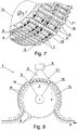
- Fig. 7
- shows a zoomed-in fragment of the drum conveyor in an isometric view with a visible track;
- Fig. 8
- shows a device for checking the quality of rod-like products moved on a drum by a stationary track located in the top part of the drum;
- Fig. 9
- shows a device for checking the quality of rod-like products moved on a drum by a movable track located in the bottom part of the drum;
-
Fig. 1 shows adevice 1 for checking the quality of rod-like products R with aconveyor 2 being atransport belt 3 provided withslots 4, and adapted to transport rod-like products R oriented transverse relative to direction of transportation. - Rod-like products R, are placed separately on the
transport belt 3, inslots 4, and distanced one after another, generally parallel to each other.Slots 4 in form of grooves placed on thetransport belt 3 generally transverse relative to the direction of transportation, and opened at one side in order to receive and transfer rod-like products. - Rod-like products R, are moved by the
transport belt 3 along a particular audit trail marked with P. During the movement, rod-like products R are introduced into a scanning area S of ascanning device 5. The scanning device performs a variety of measurements of physical properties of rod-like products moving within the scanning area. Quality parameters of the scanned rod-like product are established based on the measurement of physical properties when rod-like products are transported. As the product within the scanning area moves in relation to thescanning device 5, it is possible to assess physical parameters of rod-like products under different angles, that is in different angular positions of the product, obtaining a greater number of measurements for a single rod-like product than it is the case when a single measurement in one direction is performed. Thescanning device 5 can be a camera, scanner or other device recording a sequence of images. The scanning device can also perform indirect measurements of physical parameters, for direct measurement is not possible, for example it can determine a connection durability based on temperature of a weld considering a distance between the scanning area and welding location, flow velocity of rod-like products at this section, and a curve representing a function of welding durability in relation to temperature at the measurement point or in relation to temperature distribution along the weld. - Based on the sequence of images recorded at different angles it is possible to specify the spatial distribution of the investigated physical parameter within rod-like products, and thereby a more detailed specification of quality parameters of the scanned rod-like product considering the spatial distribution of the measured parameter of a rod-like product.
- The
scanning device 5 is placed advantageously at the opposite side of the product R in relation to thesocket 4 and theconveyor 2. Measurement of physical properties can take place by recording a series of pictures of a rod-like product R, which pictures shall be processed and/or compared with a specific pattern. Based on the evaluation of the picture and specified limits of physical properties, which determine a correct rod-like product R, certain values are assigned determining further processing of the rod-like product. If a rod-like product does not meet quality requirements, it shall be rejected from the process as defective. - Alternatively, the quality analysis may involve a construction of an analytical 3D model of a rod-like product, establishing the actual geometrical shape of the rod-like product, and determination of the difference value between the 3D model of a desired product and the acquired measurements. The differential analysis may be one-dimensional or multi-dimensional, it may involve in particular directly measured values as well as derivatives.
- Physical properties, which may be checked by the
scanning device 5, are not limited to herewith specified properties, but may include among others: product length, diameter, product curvature, adhesive seam quality, wrapper overprint position, overprint quality, wrapper perforation position, presence of wrapper damages and/or their number or their surface area. - The movement of rod-like products through the scanning area S is not sufficient for a complete scan of rod-like products, as rod-like products are visible for the scanning device only from one side, in order to perform a complete scan of a rod-like product or a scan of the entire
circumferential surface 6 of a rod-like product R, in the scanning area S, the product R is rotated at the path of a length L. The length of the path L has a value being at least equal or greater to the value of the circumference C of the product R. In the scanning area S the rod-like product R rotates around its' longitudinal axis X for an angle of at least 360° so that thescanning device 5 can scan the entirecircumferential surface 6 of the product R. It is favourable if within the scanning area S, the product R performs two complete rotations around its' own longitudinal axis X. In order to rotate the rod-like product R, thedevice 1 has at least onetrack 7 placed in the scanning area S, which interacts with thelateral surface 6 of the rod-like product R, and thus rotates the rod-like product that is pushed by walls of theslot 4 and moving along the conveyor track, which is presented in more details infig. 2 . - The movement of rod-like products is caused by the friction between rod-like products R, and
track 7, which is greater than the friction between the rod-like product R and lateral walls of theslot 4 pushing rod-like products. Rod-like products are elevated by thetrack 7 over the bottoms of theslots 4. Rod-like product elevation takes place in a place, where thetrack 7 enters into the contour of thesocket 4, meaning in the path L, thus the rod-like product is elevated bytrack 7 and rolled over its'contact surface 8. This has a particular significance in a case of a configuration where rod-like products are kept inside slots not only by effect of gravitation force but also by vacuum. - In this embodiment, the
device 1 is provided with theconveyor 2 being atransport belt 3 comprising threeparts 3b 3c basically parallel to each other, and separated bygaps 9. Thesocket 4 moving a rod-like product shall comprises threesockets transport belt Sockets sockets - Two
stationary tracks 7 parallel to each other, are placed ingaps 9 betweenparts transport belt 3, lengthwise to the transport direction T. The term stationary means that the tracks are stationary in relation to thescanning device 5, they are provided with no drive and they are not changing their spatial position.Tracks 7 are adopted to extend above thebottom surface 19 of thetransport socket 4 due to the shape of thecontact surface 8, which exemplary can have a form of a cylinder segment as infig.5 . For example, thetrack contact surface 8 can extend above thebottom surface 19 of thetransport socket 4 in the scanning area S of the audit trail, so that during the quality check of a rod-like product R, R', the rod-like product is lifted above thebottom surface 19 of thesocket 4 in a direction away from the bottom 19. - The use of two
tracks 7 for rotation of a rod-like product 7 provides a more stable support for the product during the rotation and increases traction between thetracks 7 and the circumferential surface of the rod-like product R. Other embodiments of the invention are also possible, where forexample tracks 7 will be placed on the opposite lateral sides of thebelt 3 as presented infig. 3 . In this embodiment the end parts of rod-like products R, are rolled over thecontact surface 8 oftracks 7. - It is also possible to use a single track of a greater width, which will be placed in a way enabling lifting of a rod-like product in a socket, and after lifting, end parts of the rod-like products will bent below the contact surface of the track. The track shall stay in contact with the lateral surface of the rod-like product, in location where the centre of gravity of the rod-like product is located.
-
Fig. 4 presents in an enlargement tracks 7 with an example of atoothed contact surface 8. Thecontact surface 8 or theentire track 7 can be made of rubber or plastic with such geometrical or material parameters, where the movement of a rod-like product on the track's surface will create resistance or friction greater than friction against the socket surface, thus causing a rotation of the rod-like product around its' longitudinal axis and rolling on tracks within the moving socket. Friction coefficient shall be high enough to rotate rod-like products R moved inslots 4. In order to ensure better adhesion of product R tosocket 4openings 11 providing vacuum to thesocket 4 may be placed in bottom 10.Openings 11 can be alternatively placed inlateral walls socket 4. -
Fig. 5 presents a cross-section of atransport belt 3 along the line A-A in a side view; - Rod-like products R have been shown as placed in
slots 4 in order to explain better the function of thetrack 7. - During the movement of the
transport belt 3 with rod-like products R placed inslots 4 in a direction T, at least onetrack 7 is introduced inslots 4 from thebottom side 10. In this embodiment, thetrack 7 is stationary however it is possible to use the moving track for example in the form rotational roller or cam interacting with an endless belt. - During the movement of
transport belt 3 outside scanning area S ofscanning device 5, rod-like products R rest still inslots 4, supported by the bottom 10 of sockets. When thetrack 7 is being introduced gradually into thesocket 4 from thebottom side 10, rod-like products R' are rolled in the direction T by thesocket wall 14, due to interaction of thelateral surface 6 of the rod-like product R' with thecontact surface 8 of the track, rod-like products R' rotate around their own longitudinal axis X towards the direction corresponding the movement direction T. Thereby they roll with theircircumferential surface 6 on thecontact surface 8 oftrack 7, remaining all the time at least partially insocket 4. - The
contact surface 8 of thetrack 7 shall have a high friction coefficient which will be greater from the friction coefficient ofsocket wall 14 and will enable rotation of product R'. Alternatively, thetrack contact surface 8 can have a shape creating resistance forces for sliding movement greater than the friction coefficient ofsocket wall 14, which in this case it also enables rotation of the rod-like product R'. Rod-like products R' are rolled on thecontact surface 8 of thetrack 7 in path L of thetransport belt 3, this path corresponds the length on which thecontact surface 8 is at least partially inside thesocket 4, and above the bottom 10. The length of path L shall be equal or greater to the rod circumference L ≥ 2πr, where r equals the radius of the rod-like product. Advantageous, when the length of the path L≥ 4πr. -
Fig. 6 presents the second embodiment of thedevice 1 for checking the quality of rod-like products R withconveyor 2 in form of atransport drum 15 andscanning device 5 placed along the audit trail P of products R, below thetransport drum 15. The audit trail P has been marked with a dotted line. Thetransport drum 15 is provided withslots 4 adopted to move rod-like products R oriented crosswise to the direction of theirmovement T. Slots 4 have form of long grooves placed on the circumferential surface of thetransport drum 15, basically crosswise to the direction of movement T and to drum revolution and are partially opened in order to receive and transfer rod-like products R. Usually the transport drums are provided withslots 4, to which the vacuum is applied in order to hold transported products R during revolution of adrum 15. During revolution of thedrum 15, in the scanning area S, intosockets 4 thetrack 7 is introduced from a direction of thebottom side 10, so that thecontact surface 8 is placed at least partially within the contour of thesocket 4. Rod-like products R' inslots 4, where thetrack 7 was introduced, are lifted from the bottom 10 of thesocket 4 and though the interaction of thetrack 7 withside surface 6 of rod-like products R', they are rotated around their longitudinal axis X. Products R' rotate in slots around their longitudinal axis X on path L of circumferential surface ofdrum 15, which equals the length ofcontact surface 8 oftrack 7 placed at least partially withinsockets 4. When product R' is separated from the bottom 10 through the introduction of thetrack 7 within the contour ofsocket 4, the rod-like product is still situated within the contour of thesocket 4 through the attraction towards bottom 10 created by vacuum supplied intoopenings 11 as presented infig.7 . The attraction force on the product R' towards bottom 10 depends on the value of the supplied vacuum. The attraction force has to be strong enough to sustain product R' within thesocket 4, when thetrack 7 is introduced, but also enabling a complete rotation and rolling over thecontact surface 8 of thetrack 7. Duringdrum revolution 15 in the direction T, rod-like products R placed insockets 4 are sustained by vacuum supplied to the socket throughopenings 11 and are attracted towards thebottoms 10 ofsockets 4. In a place where on audit trail P of product R, thetrack 7 begins to enter into thesocket 4, product R' engages with thecontact surface 8, therefore becomes separated from the bottom 10 and lifted, and as a result of friction or resistance forces betweenlateral surface 6 of rod-like products R, it rolls over thecontact surface 8 to the place, where thetrack 7exits sockets 4. During the entire time from entering of thetrack 7 intosocket 4, during the roll over thecontact surface 8, until the exit of the track fromsocket 4, product R' remains at least partially within the same socket. After finishing the rolling, product R is drawn by vacuum towards the bottom 10 of thesocket 4 and as there is no interaction with the track, it becomes still, due to friction force between rod-like products andsocket walls 4, rod-like product remains still within thesocket 4. - The
scanning device 5 may also be placed over thetransport drum 15, as presented infig. 8 . In this embodiment an attraction force towards the bottom 10 of thesocket 4 may equal gravitation force, affecting products R. Moreoverslots 4 may be free of openings supplying vacuum tosockets 4 and products R are sustained withinsockets 4 by acoat 16. Thedrum 15 may have thecoat 16 sustaining products R with awindow 17 for scanninglateral surface 6 of products R within the scanning area S. In this embodiment, friction or geometrical parameters of thetrack 7 are chosen to overcome the friction force both by thesocket 4 as well as thecoated surface 16 affecting rod-like products, to enable rolling of rod-like products on the track. - The
track 7 may be a stationary element as presented onfig. 1 - 8 , or a movable element as presented onfig. 9 . - Defining the track as movable relates to the possibility of changing the location of a point on its contact surface 8' in respect to the
scanning device 5. The movable track may be a roller, shaft, belt or another element, which contact surface changes its' spatial position. In this embodiment thetrack 7 is arotating roller 18, which rotates around axis Y, contrary to revolutions of thetransport drum 15. Axis Y of the track 7' is placed within the internal contour ofdrum 15, basically parallel to axis Z ofdrum 15. The circumferential surface ofroller 18 is the contact surface 8', which enters from thebottom side 10 into thesocket 4. Path L of circumferential surface ofroller 18, placed withslots 4, in this embodiment may be shorter than the length of circumference of product R, because revolution ofroller 18 in a direction contrary to revolutions ofdrum 15 causes that rod-like product R rotates faster around its longitudinal axis X than when rolled on a stationary track presented onfig. 1-8 .
Claims (15)
- A method for checking quality of rod-like products (R, R') for the tobacco industry, comprising steps of
moving rod-like products (R, R') placed in a transport socket (4) of a conveyor (2) along an audit trail (P),
checking the quality of a rod-like products (R, R') with a scanning device (5) placed on the audit trail (P),
characterized in that it further comprises
rotating the rod-like product (R, R') placed in the transport socket (4), during the step of checking the quality of rod-like products (R, R'), using at least one track (7) interacting with a lateral surface (6) of the rod-like products (R, R'). - The method according to claim 1, characterized in that the track (7) interacts through friction with the lateral surface (6) of the rod-like product (R, R') from the bottom side (10) of the transport socket (4).
- The method according to claims 1 or 2, characterized in that the rod-like product (R, R') placed in the transport socket (4) rotates by at least 360° around its longitudinal axis (X).
- The method according to claims 1, 2 or 3 characterized in that when checking the quality of rod-like product (R, R'), the rod-like product shall be sucked in by the vacuum provided by the openings (11) in transport sockets (4) of the conveyor (2).
- The method according to claims 1, 2, 3, or 4 characterized in that the checking the quality of rod-like products (R, R') is done using a scanning device (5) in a form of camera, scanner or other device recording a plurality of images of rod-like products at different angle positions during the rolling of rod-like products on the track (7).
- The method according to claims 1, 2, 3, 4, or 5 characterized in that the step of checking the quality of rod-like products (R, R'), further comprises pushing out rod-like products (R, R') above the bottom surface (19) of the socket (4) from the bottom (10) by the track (7).
- A device for checking quality of rod-like products (R, R') for the tobacco industry comprising:a conveyor (2) provided with transport sockets (4) for moving rod-like products (R, R') along the audit trail (P),a scanning device (5) for checking the quality of the rod-like product (R, R') moving along the audit trail (P),characterized in thatthe device (1) is provided with at least one track (7) adopted to rotate rod-like products (R, R') in the socket (4) of the conveyor through interaction with a circumferential surface (6) of the rod-like product (R, R').
- The device according to claim 7 characterized in that the scanning device (7) is in a form of camera, scanner or other image recording device.
- The device according to claims 7 or 8 characterized in that the track (7) is stationary in relation to the scanning device (5).
- The device according to claims 7 or 8 characterized in that the track (7) is movable in relation to the scanning device (5).
- The device according to any of claims 7, 8, 9 or 10 characterized in that the track (7) is provided with a contact surface (8) of high friction coefficient interacting through friction with a circumferential surface (6) of rod-like products (R, R') preventing rod-like products from sliding during the rotation.
- The device according to claim 11 characterized in that the contact surface (8) is toothed or made of rubber.
- The device according to any of claims 7 to 12 characterized in that the conveyor (2) is a transport belt or a drum.
- The device according to any of claims 7 to 13 characterized in that the transport socket (4) is provided with at least one opening (11) feeding the vacuum to keep the rod-like product (R, R') in the transport socket (4).
- The device according to one of claims 7 to 14 characterized in that in scanning area (S), the contact surface (8) of the track (7) protrudes over the bottom surface (19) of transport socket (4).
Priority Applications (4)
| Application Number | Priority Date | Filing Date | Title |
|---|---|---|---|
| EP19184688.0A EP3760057B2 (en) | 2019-07-05 | 2019-07-05 | The method and device for checking the quality of rod-like products |
| PL19184688.0T PL3760057T3 (en) | 2019-07-05 | 2019-07-05 | The method and device for checking the quality of rod-like products |
| US16/946,072 US20210000164A1 (en) | 2019-07-05 | 2020-06-04 | Method and device for checking the quality of rod-like products |
| CN202010619074.9A CN112173545A (en) | 2019-07-05 | 2020-07-01 | Method and device for checking the quality of rod-shaped products |
Applications Claiming Priority (1)
| Application Number | Priority Date | Filing Date | Title |
|---|---|---|---|
| EP19184688.0A EP3760057B2 (en) | 2019-07-05 | 2019-07-05 | The method and device for checking the quality of rod-like products |
Publications (3)
| Publication Number | Publication Date |
|---|---|
| EP3760057A1 true EP3760057A1 (en) | 2021-01-06 |
| EP3760057B1 EP3760057B1 (en) | 2023-02-01 |
| EP3760057B2 EP3760057B2 (en) | 2025-10-22 |
Family
ID=67437547
Family Applications (1)
| Application Number | Title | Priority Date | Filing Date |
|---|---|---|---|
| EP19184688.0A Active EP3760057B2 (en) | 2019-07-05 | 2019-07-05 | The method and device for checking the quality of rod-like products |
Country Status (4)
| Country | Link |
|---|---|
| US (1) | US20210000164A1 (en) |
| EP (1) | EP3760057B2 (en) |
| CN (1) | CN112173545A (en) |
| PL (1) | PL3760057T3 (en) |
Families Citing this family (3)
| Publication number | Priority date | Publication date | Assignee | Title |
|---|---|---|---|---|
| WO2021122796A1 (en) * | 2019-12-16 | 2021-06-24 | Philip Morris Products S.A. | Method for assembling an aerosol generating article |
| WO2023100222A1 (en) * | 2021-11-30 | 2023-06-08 | 日本たばこ産業株式会社 | Seam inspection device and seam inspection method for cigarette filter |
| CN117302843B (en) * | 2023-10-11 | 2025-09-23 | 南通众旺金属制品有限公司 | A loading and unloading device for automobile parts transport rack |
Citations (5)
| Publication number | Priority date | Publication date | Assignee | Title |
|---|---|---|---|---|
| EP0812548A1 (en) | 1996-06-10 | 1997-12-17 | G.D S.p.A. | A method and a device for monitoring the external integrity of cigarettes |
| US6169600B1 (en) | 1998-11-20 | 2001-01-02 | Acuity Imaging, Llc | Cylindrical object surface inspection system |
| US20040173226A1 (en) | 2001-09-25 | 2004-09-09 | Chihiro Hanaoka | Device for inspecting apparatus of a rod-like article |
| WO2017208103A1 (en) * | 2016-06-03 | 2017-12-07 | International Tobacco Machinery Poland Sp. Z O.O. | Apparatus for identification of physical parameters of rod-like articles of the tobacco industry |
| US20190133178A1 (en) * | 2016-06-10 | 2019-05-09 | International Tobacco Machinery Poland Sp. Z O.O. | Apparatus for determination of the position of an insert in rod-like articles of the tobacco industry |
Family Cites Families (10)
| Publication number | Priority date | Publication date | Assignee | Title |
|---|---|---|---|---|
| IT1181265B (en) | 1984-12-06 | 1987-09-23 | Gd Spa | DEVICE FOR THE TRANSFER OF BAR-SHAPED ITEMS |
| IT1246008B (en) | 1991-06-06 | 1994-11-07 | Gd Spa | METHOD AND DEVICE FOR THE CONTROL OF THE EXTERNAL INTEGRITY OF CIGARETTES. |
| US5228462A (en) | 1992-05-27 | 1993-07-20 | Philip Morris Incorporated | Cigarette inspection device |
| DE4218266A1 (en) | 1992-06-03 | 1993-12-09 | Hauni Werke Koerber & Co Kg | Device for rotating cigarettes conveyed on a rotating conveyor |
| US5366096A (en) | 1993-11-17 | 1994-11-22 | Brown & Williamson Tobacco Corp. | Apparatus for and method of automatically detecting and eliminating cigarettes with visual defects during cigarette manufacture |
| DE19708836A1 (en) | 1997-03-05 | 1998-09-10 | Hauni Maschinenbau Ag | Device for changing the frontal distance between rod-shaped articles of the tobacco processing industry |
| IT1295223B1 (en) | 1997-10-14 | 1999-05-04 | Gd Spa | FILTER MACHINE FOR THE PRODUCTION OF VENTILATED TOBACCO PRODUCTS |
| JP2000014376A (en) | 1998-06-30 | 2000-01-18 | Japan Tobacco Inc | Device and method for examining filter rod for cigarette |
| DE102011003466A1 (en) | 2011-02-01 | 2012-08-02 | Hauni Maschinenbau Ag | Manufacture of rod-shaped articles of the tobacco processing industry |
| DE102012216048A1 (en) | 2012-09-11 | 2014-03-13 | Hauni Maschinenbau Ag | Conveying drum for conveying rod-shaped articles e.g. filter cigarettes to filter setting machine in tobacco processing industry, has grooved disc rotating structure in which grooves are formed for receiving rod-shaped articles |
-
2019
- 2019-07-05 PL PL19184688.0T patent/PL3760057T3/en unknown
- 2019-07-05 EP EP19184688.0A patent/EP3760057B2/en active Active
-
2020
- 2020-06-04 US US16/946,072 patent/US20210000164A1/en not_active Abandoned
- 2020-07-01 CN CN202010619074.9A patent/CN112173545A/en active Pending
Patent Citations (5)
| Publication number | Priority date | Publication date | Assignee | Title |
|---|---|---|---|---|
| EP0812548A1 (en) | 1996-06-10 | 1997-12-17 | G.D S.p.A. | A method and a device for monitoring the external integrity of cigarettes |
| US6169600B1 (en) | 1998-11-20 | 2001-01-02 | Acuity Imaging, Llc | Cylindrical object surface inspection system |
| US20040173226A1 (en) | 2001-09-25 | 2004-09-09 | Chihiro Hanaoka | Device for inspecting apparatus of a rod-like article |
| WO2017208103A1 (en) * | 2016-06-03 | 2017-12-07 | International Tobacco Machinery Poland Sp. Z O.O. | Apparatus for identification of physical parameters of rod-like articles of the tobacco industry |
| US20190133178A1 (en) * | 2016-06-10 | 2019-05-09 | International Tobacco Machinery Poland Sp. Z O.O. | Apparatus for determination of the position of an insert in rod-like articles of the tobacco industry |
Also Published As
| Publication number | Publication date |
|---|---|
| EP3760057B1 (en) | 2023-02-01 |
| PL3760057T3 (en) | 2023-05-08 |
| US20210000164A1 (en) | 2021-01-07 |
| CN112173545A (en) | 2021-01-05 |
| EP3760057B2 (en) | 2025-10-22 |
Similar Documents
| Publication | Publication Date | Title |
|---|---|---|
| EP3760057B1 (en) | The method and device for checking the quality of rod-like products | |
| US11076635B2 (en) | Method, mechanism and apparatus for momentary compression of filter material | |
| CN103491812B (en) | Conveying of rod-shaped products in the tobacco processing industry | |
| CN100519345C (en) | Parallel cigarette filter assembly including particulate-filled cavities | |
| US6578583B2 (en) | Apparatus for making and inspecting multi-component wrapped article | |
| RU2556915C2 (en) | High-speed packaging device | |
| US20210368858A1 (en) | A replenishing device, an apparatus for manufacturing multi-segment rods and a method for manufacturing multi-segment rods | |
| US7338421B2 (en) | Method and a device for making filters for tobacco products | |
| CN101856145B (en) | Method for optical control of wrapping paper strips for the tobacco industry | |
| CN110228713B (en) | Conveying roller for tobacco processing industry | |
| CN106617282A (en) | Pushing drum for tobacco processing industry | |
| JPH0225705A (en) | Method and device for detecting diameter of cylindrical article in tobacco processing industry | |
| JP2010142224A (en) | Method of setting up and managing inspection device in machine for manufacturing tobacco product | |
| CN103385541B (en) | The manufacture of cigarette with filter tip | |
| US10653176B2 (en) | Apparatus for manufacturing of multi-element rods of tobacco industry | |
| US7784356B2 (en) | Inspection systems and methods for multi-segment products | |
| CN103653241B (en) | Method and drum-type machine for conveying tobacco rod-shaped products | |
| US20230180820A1 (en) | Apparatus and method for manufacturing a roll of crimped filling material for rod-like articles | |
| US20060081443A1 (en) | Device and method for conveying transverse axially rod-shaped articles of the tobacco-processing industry | |
| CN111410029A (en) | Pushing of rod-shaped articles of the tobacco processing industry | |
| ITBO970638A1 (en) | METHOD AND UNIT TO FEED A CONTINUOUS TAPE OF PRE-IMPREGNATED WRAPPING MATERIAL, WITH A FLAVORING SUBSTANCE, IN A PRODUCT WRAPPING MACHINE. | |
| CN103476276B (en) | Conveying of rod-shaped products in the tobacco processing industry | |
| PL243649B1 (en) | Method and device for checking the quality of rod-like articles | |
| CN114867369B (en) | Conveying roller for tobacco processing industry | |
| NL8102699A (en) | DEVICE FOR ATTACHING FILTERS TO CIGARETTES. |
Legal Events
| Date | Code | Title | Description |
|---|---|---|---|
| PUAI | Public reference made under article 153(3) epc to a published international application that has entered the european phase |
Free format text: ORIGINAL CODE: 0009012 |
|
| STAA | Information on the status of an ep patent application or granted ep patent |
Free format text: STATUS: THE APPLICATION HAS BEEN PUBLISHED |
|
| AK | Designated contracting states |
Kind code of ref document: A1 Designated state(s): AL AT BE BG CH CY CZ DE DK EE ES FI FR GB GR HR HU IE IS IT LI LT LU LV MC MK MT NL NO PL PT RO RS SE SI SK SM TR |
|
| AX | Request for extension of the european patent |
Extension state: BA ME |
|
| STAA | Information on the status of an ep patent application or granted ep patent |
Free format text: STATUS: REQUEST FOR EXAMINATION WAS MADE |
|
| 17P | Request for examination filed |
Effective date: 20210706 |
|
| RBV | Designated contracting states (corrected) |
Designated state(s): AL AT BE BG CH CY CZ DE DK EE ES FI FR GB GR HR HU IE IS IT LI LT LU LV MC MK MT NL NO PL PT RO RS SE SI SK SM TR |
|
| RIC1 | Information provided on ipc code assigned before grant |
Ipc: A24C 5/34 20060101AFI20221011BHEP |
|
| GRAP | Despatch of communication of intention to grant a patent |
Free format text: ORIGINAL CODE: EPIDOSNIGR1 |
|
| STAA | Information on the status of an ep patent application or granted ep patent |
Free format text: STATUS: GRANT OF PATENT IS INTENDED |
|
| INTG | Intention to grant announced |
Effective date: 20221125 |
|
| GRAS | Grant fee paid |
Free format text: ORIGINAL CODE: EPIDOSNIGR3 |
|
| GRAA | (expected) grant |
Free format text: ORIGINAL CODE: 0009210 |
|
| STAA | Information on the status of an ep patent application or granted ep patent |
Free format text: STATUS: THE PATENT HAS BEEN GRANTED |
|
| AK | Designated contracting states |
Kind code of ref document: B1 Designated state(s): AL AT BE BG CH CY CZ DE DK EE ES FI FR GB GR HR HU IE IS IT LI LT LU LV MC MK MT NL NO PL PT RO RS SE SI SK SM TR |
|
| REG | Reference to a national code |
Ref country code: GB Ref legal event code: FG4D |
|
| REG | Reference to a national code |
Ref country code: CH Ref legal event code: EP Ref country code: AT Ref legal event code: REF Ref document number: 1546692 Country of ref document: AT Kind code of ref document: T Effective date: 20230215 |
|
| REG | Reference to a national code |
Ref country code: DE Ref legal event code: R096 Ref document number: 602019024986 Country of ref document: DE |
|
| REG | Reference to a national code |
Ref country code: IE Ref legal event code: FG4D |
|
| REG | Reference to a national code |
Ref country code: LT Ref legal event code: MG9D |
|
| REG | Reference to a national code |
Ref country code: NL Ref legal event code: MP Effective date: 20230201 |
|
| P01 | Opt-out of the competence of the unified patent court (upc) registered |
Effective date: 20230418 |
|
| REG | Reference to a national code |
Ref country code: AT Ref legal event code: MK05 Ref document number: 1546692 Country of ref document: AT Kind code of ref document: T Effective date: 20230201 |
|
| PG25 | Lapsed in a contracting state [announced via postgrant information from national office to epo] |
Ref country code: RS Free format text: LAPSE BECAUSE OF FAILURE TO SUBMIT A TRANSLATION OF THE DESCRIPTION OR TO PAY THE FEE WITHIN THE PRESCRIBED TIME-LIMIT Effective date: 20230201 Ref country code: PT Free format text: LAPSE BECAUSE OF FAILURE TO SUBMIT A TRANSLATION OF THE DESCRIPTION OR TO PAY THE FEE WITHIN THE PRESCRIBED TIME-LIMIT Effective date: 20230601 Ref country code: NO Free format text: LAPSE BECAUSE OF FAILURE TO SUBMIT A TRANSLATION OF THE DESCRIPTION OR TO PAY THE FEE WITHIN THE PRESCRIBED TIME-LIMIT Effective date: 20230501 Ref country code: NL Free format text: LAPSE BECAUSE OF FAILURE TO SUBMIT A TRANSLATION OF THE DESCRIPTION OR TO PAY THE FEE WITHIN THE PRESCRIBED TIME-LIMIT Effective date: 20230201 Ref country code: LV Free format text: LAPSE BECAUSE OF FAILURE TO SUBMIT A TRANSLATION OF THE DESCRIPTION OR TO PAY THE FEE WITHIN THE PRESCRIBED TIME-LIMIT Effective date: 20230201 Ref country code: LT Free format text: LAPSE BECAUSE OF FAILURE TO SUBMIT A TRANSLATION OF THE DESCRIPTION OR TO PAY THE FEE WITHIN THE PRESCRIBED TIME-LIMIT Effective date: 20230201 Ref country code: HR Free format text: LAPSE BECAUSE OF FAILURE TO SUBMIT A TRANSLATION OF THE DESCRIPTION OR TO PAY THE FEE WITHIN THE PRESCRIBED TIME-LIMIT Effective date: 20230201 Ref country code: ES Free format text: LAPSE BECAUSE OF FAILURE TO SUBMIT A TRANSLATION OF THE DESCRIPTION OR TO PAY THE FEE WITHIN THE PRESCRIBED TIME-LIMIT Effective date: 20230201 Ref country code: AT Free format text: LAPSE BECAUSE OF FAILURE TO SUBMIT A TRANSLATION OF THE DESCRIPTION OR TO PAY THE FEE WITHIN THE PRESCRIBED TIME-LIMIT Effective date: 20230201 |
|
| PG25 | Lapsed in a contracting state [announced via postgrant information from national office to epo] |
Ref country code: SE Free format text: LAPSE BECAUSE OF FAILURE TO SUBMIT A TRANSLATION OF THE DESCRIPTION OR TO PAY THE FEE WITHIN THE PRESCRIBED TIME-LIMIT Effective date: 20230201 Ref country code: IS Free format text: LAPSE BECAUSE OF FAILURE TO SUBMIT A TRANSLATION OF THE DESCRIPTION OR TO PAY THE FEE WITHIN THE PRESCRIBED TIME-LIMIT Effective date: 20230601 Ref country code: GR Free format text: LAPSE BECAUSE OF FAILURE TO SUBMIT A TRANSLATION OF THE DESCRIPTION OR TO PAY THE FEE WITHIN THE PRESCRIBED TIME-LIMIT Effective date: 20230502 Ref country code: FI Free format text: LAPSE BECAUSE OF FAILURE TO SUBMIT A TRANSLATION OF THE DESCRIPTION OR TO PAY THE FEE WITHIN THE PRESCRIBED TIME-LIMIT Effective date: 20230201 |
|
| REG | Reference to a national code |
Ref country code: DE Ref legal event code: R026 Ref document number: 602019024986 Country of ref document: DE |
|
| PG25 | Lapsed in a contracting state [announced via postgrant information from national office to epo] |
Ref country code: SM Free format text: LAPSE BECAUSE OF FAILURE TO SUBMIT A TRANSLATION OF THE DESCRIPTION OR TO PAY THE FEE WITHIN THE PRESCRIBED TIME-LIMIT Effective date: 20230201 Ref country code: RO Free format text: LAPSE BECAUSE OF FAILURE TO SUBMIT A TRANSLATION OF THE DESCRIPTION OR TO PAY THE FEE WITHIN THE PRESCRIBED TIME-LIMIT Effective date: 20230201 Ref country code: EE Free format text: LAPSE BECAUSE OF FAILURE TO SUBMIT A TRANSLATION OF THE DESCRIPTION OR TO PAY THE FEE WITHIN THE PRESCRIBED TIME-LIMIT Effective date: 20230201 Ref country code: DK Free format text: LAPSE BECAUSE OF FAILURE TO SUBMIT A TRANSLATION OF THE DESCRIPTION OR TO PAY THE FEE WITHIN THE PRESCRIBED TIME-LIMIT Effective date: 20230201 Ref country code: CZ Free format text: LAPSE BECAUSE OF FAILURE TO SUBMIT A TRANSLATION OF THE DESCRIPTION OR TO PAY THE FEE WITHIN THE PRESCRIBED TIME-LIMIT Effective date: 20230201 |
|
| PLBI | Opposition filed |
Free format text: ORIGINAL CODE: 0009260 |
|
| PLAX | Notice of opposition and request to file observation + time limit sent |
Free format text: ORIGINAL CODE: EPIDOSNOBS2 |
|
| PG25 | Lapsed in a contracting state [announced via postgrant information from national office to epo] |
Ref country code: SK Free format text: LAPSE BECAUSE OF FAILURE TO SUBMIT A TRANSLATION OF THE DESCRIPTION OR TO PAY THE FEE WITHIN THE PRESCRIBED TIME-LIMIT Effective date: 20230201 |
|
| 26 | Opposition filed |
Opponent name: G.D S.P.A. Effective date: 20231030 |
|
| PG25 | Lapsed in a contracting state [announced via postgrant information from national office to epo] |
Ref country code: SI Free format text: LAPSE BECAUSE OF FAILURE TO SUBMIT A TRANSLATION OF THE DESCRIPTION OR TO PAY THE FEE WITHIN THE PRESCRIBED TIME-LIMIT Effective date: 20230201 |
|
| PG25 | Lapsed in a contracting state [announced via postgrant information from national office to epo] |
Ref country code: MC Free format text: LAPSE BECAUSE OF FAILURE TO SUBMIT A TRANSLATION OF THE DESCRIPTION OR TO PAY THE FEE WITHIN THE PRESCRIBED TIME-LIMIT Effective date: 20230201 |
|
| PG25 | Lapsed in a contracting state [announced via postgrant information from national office to epo] |
Ref country code: MC Free format text: LAPSE BECAUSE OF FAILURE TO SUBMIT A TRANSLATION OF THE DESCRIPTION OR TO PAY THE FEE WITHIN THE PRESCRIBED TIME-LIMIT Effective date: 20230201 |
|
| PLBB | Reply of patent proprietor to notice(s) of opposition received |
Free format text: ORIGINAL CODE: EPIDOSNOBS3 |
|
| REG | Reference to a national code |
Ref country code: BE Ref legal event code: MM Effective date: 20230731 |
|
| PG25 | Lapsed in a contracting state [announced via postgrant information from national office to epo] |
Ref country code: LU Free format text: LAPSE BECAUSE OF NON-PAYMENT OF DUE FEES Effective date: 20230705 |
|
| GBPC | Gb: european patent ceased through non-payment of renewal fee |
Effective date: 20230705 |
|
| PG25 | Lapsed in a contracting state [announced via postgrant information from national office to epo] |
Ref country code: LU Free format text: LAPSE BECAUSE OF NON-PAYMENT OF DUE FEES Effective date: 20230705 |
|
| REG | Reference to a national code |
Ref country code: IE Ref legal event code: MM4A |
|
| PG25 | Lapsed in a contracting state [announced via postgrant information from national office to epo] |
Ref country code: GB Free format text: LAPSE BECAUSE OF NON-PAYMENT OF DUE FEES Effective date: 20230705 |
|
| PG25 | Lapsed in a contracting state [announced via postgrant information from national office to epo] |
Ref country code: FR Free format text: LAPSE BECAUSE OF NON-PAYMENT OF DUE FEES Effective date: 20230731 Ref country code: BE Free format text: LAPSE BECAUSE OF NON-PAYMENT OF DUE FEES Effective date: 20230731 |
|
| PG25 | Lapsed in a contracting state [announced via postgrant information from national office to epo] |
Ref country code: IE Free format text: LAPSE BECAUSE OF NON-PAYMENT OF DUE FEES Effective date: 20230705 |
|
| PG25 | Lapsed in a contracting state [announced via postgrant information from national office to epo] |
Ref country code: IE Free format text: LAPSE BECAUSE OF NON-PAYMENT OF DUE FEES Effective date: 20230705 |
|
| PGFP | Annual fee paid to national office [announced via postgrant information from national office to epo] |
Ref country code: PL Payment date: 20240701 Year of fee payment: 6 |
|
| PG25 | Lapsed in a contracting state [announced via postgrant information from national office to epo] |
Ref country code: BG Free format text: LAPSE BECAUSE OF FAILURE TO SUBMIT A TRANSLATION OF THE DESCRIPTION OR TO PAY THE FEE WITHIN THE PRESCRIBED TIME-LIMIT Effective date: 20230201 |
|
| PG25 | Lapsed in a contracting state [announced via postgrant information from national office to epo] |
Ref country code: BG Free format text: LAPSE BECAUSE OF FAILURE TO SUBMIT A TRANSLATION OF THE DESCRIPTION OR TO PAY THE FEE WITHIN THE PRESCRIBED TIME-LIMIT Effective date: 20230201 |
|
| PG25 | Lapsed in a contracting state [announced via postgrant information from national office to epo] |
Ref country code: CY Free format text: LAPSE BECAUSE OF FAILURE TO SUBMIT A TRANSLATION OF THE DESCRIPTION OR TO PAY THE FEE WITHIN THE PRESCRIBED TIME-LIMIT; INVALID AB INITIO Effective date: 20190705 |
|
| PG25 | Lapsed in a contracting state [announced via postgrant information from national office to epo] |
Ref country code: HU Free format text: LAPSE BECAUSE OF FAILURE TO SUBMIT A TRANSLATION OF THE DESCRIPTION OR TO PAY THE FEE WITHIN THE PRESCRIBED TIME-LIMIT; INVALID AB INITIO Effective date: 20190705 |
|
| PUAH | Patent maintained in amended form |
Free format text: ORIGINAL CODE: 0009272 |
|
| STAA | Information on the status of an ep patent application or granted ep patent |
Free format text: STATUS: PATENT MAINTAINED AS AMENDED |
|
| PGFP | Annual fee paid to national office [announced via postgrant information from national office to epo] |
Ref country code: DE Payment date: 20250722 Year of fee payment: 7 |
|
| PGFP | Annual fee paid to national office [announced via postgrant information from national office to epo] |
Ref country code: IT Payment date: 20250724 Year of fee payment: 7 |
|
| PGFP | Annual fee paid to national office [announced via postgrant information from national office to epo] |
Ref country code: CH Payment date: 20250801 Year of fee payment: 7 |
|
| 27A | Patent maintained in amended form |
Effective date: 20251022 |
|
| AK | Designated contracting states |
Kind code of ref document: B2 Designated state(s): AL AT BE BG CH CY CZ DE DK EE ES FI FR GB GR HR HU IE IS IT LI LT LU LV MC MK MT NL NO PL PT RO RS SE SI SK SM TR |
|
| REG | Reference to a national code |
Ref country code: DE Ref legal event code: R102 Ref document number: 602019024986 Country of ref document: DE |
|
| PG25 | Lapsed in a contracting state [announced via postgrant information from national office to epo] |
Ref country code: TR Free format text: LAPSE BECAUSE OF FAILURE TO SUBMIT A TRANSLATION OF THE DESCRIPTION OR TO PAY THE FEE WITHIN THE PRESCRIBED TIME-LIMIT Effective date: 20230201 |