EP3759014B1 - Crawled vehicle for the preparation of ski pistes - Google Patents
Crawled vehicle for the preparation of ski pistes Download PDFInfo
- Publication number
- EP3759014B1 EP3759014B1 EP19712628.7A EP19712628A EP3759014B1 EP 3759014 B1 EP3759014 B1 EP 3759014B1 EP 19712628 A EP19712628 A EP 19712628A EP 3759014 B1 EP3759014 B1 EP 3759014B1
- Authority
- EP
- European Patent Office
- Prior art keywords
- wheels
- wheel
- supporting element
- frame
- supporting
- Prior art date
- Legal status (The legal status is an assumption and is not a legal conclusion. Google has not performed a legal analysis and makes no representation as to the accuracy of the status listed.)
- Active
Links
Images

Classifications
-
- B—PERFORMING OPERATIONS; TRANSPORTING
- B62—LAND VEHICLES FOR TRAVELLING OTHERWISE THAN ON RAILS
- B62D—MOTOR VEHICLES; TRAILERS
- B62D55/00—Endless track vehicles
- B62D55/08—Endless track units; Parts thereof
- B62D55/104—Suspension devices for wheels, rollers, bogies or frames
- B62D55/108—Suspension devices for wheels, rollers, bogies or frames with mechanical springs, e.g. torsion bars
-
- B—PERFORMING OPERATIONS; TRANSPORTING
- B62—LAND VEHICLES FOR TRAVELLING OTHERWISE THAN ON RAILS
- B62D—MOTOR VEHICLES; TRAILERS
- B62D55/00—Endless track vehicles
- B62D55/08—Endless track units; Parts thereof
- B62D55/10—Bogies; Frames
-
- B—PERFORMING OPERATIONS; TRANSPORTING
- B62—LAND VEHICLES FOR TRAVELLING OTHERWISE THAN ON RAILS
- B62D—MOTOR VEHICLES; TRAILERS
- B62D55/00—Endless track vehicles
- B62D55/08—Endless track units; Parts thereof
- B62D55/104—Suspension devices for wheels, rollers, bogies or frames
-
- B—PERFORMING OPERATIONS; TRANSPORTING
- B62—LAND VEHICLES FOR TRAVELLING OTHERWISE THAN ON RAILS
- B62D—MOTOR VEHICLES; TRAILERS
- B62D55/00—Endless track vehicles
- B62D55/08—Endless track units; Parts thereof
- B62D55/104—Suspension devices for wheels, rollers, bogies or frames
- B62D55/112—Suspension devices for wheels, rollers, bogies or frames with fluid springs, e.g. hydraulic pneumatic
- B62D55/1125—Hydro-pneumatic or pneumatic, e.g. air-cushioned
-
- B—PERFORMING OPERATIONS; TRANSPORTING
- B60—VEHICLES IN GENERAL
- B60G—VEHICLE SUSPENSION ARRANGEMENTS
- B60G2300/00—Indexing codes relating to the type of vehicle
- B60G2300/32—Track vehicles
-
- B—PERFORMING OPERATIONS; TRANSPORTING
- B62—LAND VEHICLES FOR TRAVELLING OTHERWISE THAN ON RAILS
- B62D—MOTOR VEHICLES; TRAILERS
- B62D55/00—Endless track vehicles
- B62D55/06—Endless track vehicles with tracks without ground wheels
-
- B—PERFORMING OPERATIONS; TRANSPORTING
- B62—LAND VEHICLES FOR TRAVELLING OTHERWISE THAN ON RAILS
- B62D—MOTOR VEHICLES; TRAILERS
- B62D55/00—Endless track vehicles
- B62D55/08—Endless track units; Parts thereof
- B62D55/104—Suspension devices for wheels, rollers, bogies or frames
- B62D55/116—Attitude or position control of chassis by action on suspension, e.g. to compensate for a slope
Definitions
- the invention relates to a ski pistes preparation crawled vehicle.
- the invention relates to a crawled vehicle comprising a frame; two wheel assemblies arranged on opposite sides of the frame; two crawls arranged around the respective wheel assemblies; and at least one supporting device for each wheel assembly, which is coupled to at least two wheels of the wheel assembly and is connected to the frame so as to couple said at least two wheels of the wheel assembly to the frame.
- Examples of such vehicles are shown in WO 2018/024762 A2 , WO 2018/024758 A2 , US 2 386 620 A and US 3 285 676 A .
- a drawback of the prior art lies in the fact that said crawled vehicle has undesired vibrations.
- An object of the invention is to provide a ski pistes preparation crawled vehicle which is capable of reducing the drawback of the prior art.
- a ski pistes preparation crawled vehicle comprising:
- the two wheels of the wheel assembly are connected to one another through the supporting device, so as to have at least one degree of freedom of movement relative to one another, which reduces the vibrations transmitted to the frame.
- the first supporting element and the second supporting element are connected to one another through an elastic structure, in particular a leaf spring, a fibreglass structure or a carbon structure.
- the supporting device comprises an elastic structure, in particular a leaf spring, a fibreglass structure or a carbon structure; the first supporting element and the second supporting element, in particular the first supporting element and the second supporting element are defined by respective portions or by respective ends of the elastic structure, in particular by respective portions or ends of the leaf spring or fibreglass structure or carbon structure.
- the supporting device comprises a further articulated joint to couple the first supporting element to the second supporting element in an articulated manner, said further articulated joint preferably is a hinge.
- the first and the second supporting element are connected to one another through a shock absorber, in particular in a second point different from the first point.
- the shock absorber has a variable stiffness and/or a variable geometry.
- the shock absorber is mechanical and/or hydraulic and/or electromagnetic and/or an air suspension or any combination thereof.
- the supporting device comprises a connection articulated joint coupled to the frame in order to couple the supporting device to the frame in an articulated manner;
- the articulated connection joint preferably is a hinge.
- connection articulated joint is partly housed on the first and/or on the second supporting element.
- said at least two wheels of the wheel assembly are supporting wheel in particular free rotating wheel.
- the supporting device is connected to the frame through a shock absorber assembly.
- the shock absorber assembly has a variable stiffness and/or a variable geometry
- the shock absorber assembly comprises a double-acting hydraulic cylinder.
- the shock absorber assembly is mechanical and/or hydraulic and/or electromagnetic and/or an air suspension or any combination thereof.
- each wheel assembly comprises a crawl regulating wheel, preferably a front wheel, a driving wheel, preferably a rear wheel, two pairs of supporting wheels and two supporting devices, each coupled to one respective pair of supporting wheels.
- number 1 defines, as a whole, a crawled vehicle, in particular a crawled vehicle for the preparation of ski pistes, designed to be moved in a moving direction D ( figure 4 ).
- the crawled vehicle 1 comprises a frame 2; two wheel assemblies 3 (only one of them is shown in figure 1 ) with a variable configuration and arranged on opposite sides of the frame 2; and two crawls 4, each wound around one of the two respective wheel assemblies 3.
- the frame 2 extends along an axis A and supports the wheel assemblies 3.
- Each wheel assembly 3 comprises a front wheel 3a, a rear wheel 3b and four central wheels 3c arranged between the front wheel 3a and the rear wheel 3b.
- the wheel 3b is a driving wheel.
- each front wheel 3a is connected to the frame 2 by means of a carriage 50, which is coupled to the frame 2 so that it can slide along the direction of extension of the crawl 3 (preferably parallel to the moving direction) by means of an actuator, which is not shown in the accompanying figure, in order to keep the respective crawl 4 stretched in any configuration assumed by the remaining wheels 3 of the wheel assembly 3.
- the crawled vehicle 1 comprises a control assembly 5; a cabin 6; a user interface 7 arranged in the cabin 6; a shovel 8, which is supported by the frame 2 on the front side; a cutter 9, which is supported by the frame 2 on the rear side; a winch assembly 10, which is fixed above the frame 2; and internal combustion engine 11; and a powertrain 12, which is operatively connected to the internal combustion engine 11; to the driving wheels 3b; to the shovel 8; to the cutter 9; and to the winch assembly 10.
- the powertrain 12 can be hydraulic or electric or a combination of hydraulic and electric.
- each wheel assembly 3 can be adjusted between to limit configurations, so as to adjust a crawl portion in contact with the snow surface M.
- each wheel assembly 3 is coupled two by two to respective supporting devices 15, which, in turn, are connected to the frame 2 in a movable manner.
- the crawled vehicle 1 For each supporting device 15, the crawled vehicle 1 comprises a shock absorber assembly 160 with a variable configuration and a variable stiffness to connect the respective two central wheels 3c, in particular through the supporting devices 15, to the frame 2, absorb possible hits and selectively change the position between the central wheels 3c and the frame 2.
- a shock absorber assembly 160 with a variable configuration and a variable stiffness to connect the respective two central wheels 3c, in particular through the supporting devices 15, to the frame 2, absorb possible hits and selectively change the position between the central wheels 3c and the frame 2.
- each supporting device 15 is connected to the frame through a respective shock absorber assembly 160.
- the shock absorber assembly 160 has a variable stiffness and a variable geometry, so as to change the reaction of the shock absorber assembly 160 to hits and be able to change the position of the crawled vehicle relative to the snow and of the crawl portion in contact with the snow.
- the crawled vehicle 1 comprises a supporting device 15 for each pair of central wheels 3c of the wheel assembly 3.
- each supporting device 15 is coupled to two central wheels 3c of the wheel assembly 3; as a consequence, for each wheel assembly 3, the crawled vehicle 1 comprises two supporting devices 15.
- Each supporting device 15 is coupled to two central wheels 3c.
- each supporting device 15 couples the respective two central wheels 3c of the wheel assembly 3 to the frame 2 in an articulated manner, so as to couple said at least two central wheels 3c of the wheel assembly 3 to the frame 2.
- the supporting device 15 has a first supporting element 16, which supports one of the two central wheels 3c; and a second supporting element 17, which supports another one of the two central wheels 3c; and wherein the first supporting element 16 and the second supporting element 17 are connected to one another through a first articulated joint 18 in a first point 19.
- the first articulated joint 18 preferably is a hinge.
- the first and the second supporting element 16 and 17 are connected to one another through a shock absorber 20, in particular in points 21 that are different from the point 19.
- the supporting device 15 comprises the shock absorber 20, which is connected to the first and to the second element by means of articulated joints 22 placed in the points 21, in particular two articulated joints 22 in the two points 21.
- the articulated joints 22 preferably are hinges.
- the shock absorber 20 has a variable stiffness.
- the shock absorber 20 has a variable geometry.
- the shock absorber 20 has a variable stiffness and a variable geometry.
- shock absorber (20) is mechanical and/or hydraulic and/or electromagnetic and/or an air suspension or any combination thereof.
- the supporting device 15 comprises a connection articulated joint 123, which is partly housed on the first supporting element 16 and is coupled to the frame 2 so as to couple the supporting device 15 to the frame 2 in an articulated manner.
- the articulated joint 123 preferably is a hinge.
- the central wheels 3c are supporting wheels, in particular they are free rotating wheels. Furthermore, the central wheels 3c are middle wheels, which are placed between the front wheel 3a and the rear wheel 3b.
- each shock absorber assembly 160 comprises a mechanical connection arranged between the frame 2 and the supporting device 15.
- the mechanical connection comprises a double-acting hydraulic cylinder 23, a crank 24 and a plate 25 supporting the crank 24.
- the support device 15 comprises two attachments 26 for the two respective central wheels 3c around two rotation axes A1, which are transverse to the axis A ( figure 1 ).
- the crank 24 comprises a shaft 27 with axis A2, which is parallel to the axes A1 and is mounted so as to rotate around the axis A2 in the support plate 25 fixed to the frame 2; an arm 29, which is integral to the shaft 27 and is mounted so as to rotate, at an end of the hydraulic cylinder 23, around an axis A4, which is parallel to the axes A1.
- the hydraulic cylinder 23 has a first end fixed to the frame 2 so as to rotate around an axis A5, which is parallel to the axes A1. In this way, by changing the length of the hydraulic cylinder 23, it is possible to change the distance of the supporting device 15 from the frame 2 or, even better, the distance of the axis A2 from the frame 2, because the supporting device 15 can freely oscillate around the axis A2 and, hence, change the position of the respective central wheels 3 relative to the frame 2.
- the control assembly 5 comprises a control unit 13 and the user interface 7 and has the function of acquiring a signal indicating an operating state of the crawled vehicle 1 as a function of at least one operating parameter of the crawled vehicle and, preferably, of a plurality of operating parameters, as well as the function of adjusting the configurations of the wheel assemblies 3 as a function of the signal indicating the operating state, in particular the function of adjusting the configuration and/or the stiffness of the shock absorber assemblies 160.
- control units 13 through the signal indicating the operating state, controls the shock absorbers 20 one by one or jointly.
- the driver controls both the position and the stiffness of the shock absorber assembly 160 and/or of each shock absorber or of all shock absorbers 20 through the support of the displaying on the user interface 7.
- the supporting device 15 is replaced by a supporting device 115.
- the supporting device 115 comprises an elastic structure 225, in particular a leaf spring, as well as a first supporting element 116 and a second supporting element 117, which are arranged at respective ends of the elastic structure 225, in particular of the leaf spring, where two respective central wheels 3c are connected and supported.
- the ends of the spring leas 225 define the first and the second supporting element 116 and 117.
- the elastic structure is defined by a fibreglass structure or a carbon structure comprising, at the respective ends, two supporting elements, which are connected to two respective central wheels 3c.
- the supporting device 115 similarly to the supporting device 15, comprises a connection articulated joint 223, which is connected to the elastic structure 225 by means of a connection element 226.
- the connection articulated joint 223 is coupled to the frame 2 so as to couple the supporting device 115 to the frame 2 in an articulated manner.
- the articulated joint 223 preferably is a hinge.
- the elastic structure 225 allows the central wheels 3c to make movements in the range of 60 mm around the balance position, preferably 20 mm around the balance position.
Landscapes
- Engineering & Computer Science (AREA)
- Chemical & Material Sciences (AREA)
- Combustion & Propulsion (AREA)
- Transportation (AREA)
- Mechanical Engineering (AREA)
- Vehicle Body Suspensions (AREA)
- Automatic Cycles, And Cycles In General (AREA)
- Body Structure For Vehicles (AREA)
- Image Analysis (AREA)
Description
- This Patent application claims priority from
Italian Patent Application No. 102018000003244 filed on March 2, 2018 - The invention relates to a ski pistes preparation crawled vehicle.
- In particular, the invention relates to a crawled vehicle comprising a frame; two wheel assemblies arranged on opposite sides of the frame; two crawls arranged around the respective wheel assemblies; and at least one supporting device for each wheel assembly, which is coupled to at least two wheels of the wheel assembly and is connected to the frame so as to couple said at least two wheels of the wheel assembly to the frame. Examples of such vehicles are shown in
WO 2018/024762 A2 ,WO 2018/024758 A2 ,US 2 386 620 A andUS 3 285 676 A . - A drawback of the prior art lies in the fact that said crawled vehicle has undesired vibrations.
- An object of the invention is to provide a ski pistes preparation crawled vehicle which is capable of reducing the drawback of the prior art.
- According to the invention, there is provided a ski pistes preparation crawled vehicle; the crawled vehicle comprising:
- a frame;
- two wheel assemblies arranged on opposite sides of the frame;
- two crawls, each of them respectively wounded around one of the two wheel assemblies;
- at least one supporting device for each wheel assembly, which is coupled to at least two wheels of the wheel assembly and is connected in an articulated manner to the frame so as to couple said at least two wheels of the wheel assembly to the frame; wherein the supporting device has a first supporting element, which supports one of said at least two wheels of the wheel assembly; and a second supporting element, which supports another one of the two wheels of the wheel assembly; and wherein the first supporting element and the second supporting element are connected to one another in an elastically flexible manner or through a first articulated joint in a first point; the first articulated joint preferably is a hinge;
- wherein the wheels assembly comprises a driving wheel, preferably a rear wheel;
- wherein the wheels assembly comprises a regulating crawl wheel, preferably a front wheel, having a mobile position with respect to the frame to stretch the crawl;
- wherein the at least two wheels are middle wheels between the regulating crawl wheel and the driving wheel and preferably are free rotating wheels.
- Thanks to the invention, the two wheels of the wheel assembly are connected to one another through the supporting device, so as to have at least one degree of freedom of movement relative to one another, which reduces the vibrations transmitted to the frame.
- According to a preferred embodiment, the first supporting element and the second supporting element are connected to one another through an elastic structure, in particular a leaf spring, a fibreglass structure or a carbon structure.
- According to a preferred embodiment, the supporting device comprises an elastic structure, in particular a leaf spring, a fibreglass structure or a carbon structure; the first supporting element and the second supporting element, in particular the first supporting element and the second supporting element are defined by respective portions or by respective ends of the elastic structure, in particular by respective portions or ends of the leaf spring or fibreglass structure or carbon structure.
- According to a preferred embodiment, the supporting device comprises a further articulated joint to couple the first supporting element to the second supporting element in an articulated manner, said further articulated joint preferably is a hinge.
- According to another preferred embodiment, the first and the second supporting element are connected to one another through a shock absorber, in particular in a second point different from the first point.
- According to another preferred embodiment, the shock absorber has a variable stiffness and/or a variable geometry.
- According to another preferred embodiment, the shock absorber is mechanical and/or hydraulic and/or electromagnetic and/or an air suspension or any combination thereof.
- According to another preferred embodiment, the supporting device comprises a connection articulated joint coupled to the frame in order to couple the supporting device to the frame in an articulated manner; the articulated connection joint preferably is a hinge.
- According to another preferred embodiment, the connection articulated joint is partly housed on the first and/or on the second supporting element.
- According to another preferred embodiment, said at least two wheels of the wheel assembly are supporting wheel in particular free rotating wheel.
- According to another preferred embodiment, the supporting device is connected to the frame through a shock absorber assembly.
- According to another preferred embodiment, the shock absorber assembly has a variable stiffness and/or a variable geometry;
- According to another preferred embodiment, the shock absorber assembly comprises a double-acting hydraulic cylinder.
- According to another preferred embodiment, the shock absorber assembly is mechanical and/or hydraulic and/or electromagnetic and/or an air suspension or any combination thereof.
- According to another preferred embodiment, each wheel assembly comprises a crawl regulating wheel, preferably a front wheel, a driving wheel, preferably a rear wheel, two pairs of supporting wheels and two supporting devices, each coupled to one respective pair of supporting wheels.
- Other features and advantages of the invention will be best understood upon perusal of the following description of a non-limiting embodiment thereof, with reference to the accompanying drawing, wherein:
-
figure 1 is a side elevation view, with parts removed for greater clarity, of a crawled vehicle according to the invention; -
figure 2 is a side elevation view of a detail of the crawled vehicle offigure 1 ; and -
figure 3 is a perspective view of a detail of the crawled vehicle according to an embodiment of the invention; -
figure 4 is a schematic view from the top, with parts removed for greater clarity, of the crawled vehicle offigure 1 ; and -
figure 5 is a side elevation view of a detail of an alternative embodiment of the crawled vehicle. - With reference to
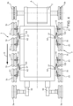
figure 1 ,number 1 defines, as a whole, a crawled vehicle, in particular a crawled vehicle for the preparation of ski pistes, designed to be moved in a moving direction D (figure 4 ). - With reference to
figure 1 , thecrawled vehicle 1 comprises aframe 2; two wheel assemblies 3 (only one of them is shown infigure 1 ) with a variable configuration and arranged on opposite sides of theframe 2; and two crawls 4, each wound around one of the tworespective wheel assemblies 3. - With reference to
figures 1 and4 , theframe 2 extends along an axis A and supports thewheel assemblies 3. - Each
wheel assembly 3 comprises afront wheel 3a, arear wheel 3b and fourcentral wheels 3c arranged between thefront wheel 3a and therear wheel 3b. Thewheel 3b is a driving wheel. - With reference to
figure 4 , eachfront wheel 3a is connected to theframe 2 by means of acarriage 50, which is coupled to theframe 2 so that it can slide along the direction of extension of the crawl 3 (preferably parallel to the moving direction) by means of an actuator, which is not shown in the accompanying figure, in order to keep the respective crawl 4 stretched in any configuration assumed by theremaining wheels 3 of thewheel assembly 3. - With reference to
figure 1 , thecrawled vehicle 1 comprises acontrol assembly 5; acabin 6; a user interface 7 arranged in thecabin 6; ashovel 8, which is supported by theframe 2 on the front side; a cutter 9, which is supported by theframe 2 on the rear side; awinch assembly 10, which is fixed above theframe 2; andinternal combustion engine 11; and apowertrain 12, which is operatively connected to theinternal combustion engine 11; to thedriving wheels 3b; to theshovel 8; to the cutter 9; and to thewinch assembly 10. Thepowertrain 12 can be hydraulic or electric or a combination of hydraulic and electric. - The configurations of the crawls 4 depend on the configurations of the
respective wheel assemblies 3. In particular, eachwheel assembly 3 can be adjusted between to limit configurations, so as to adjust a crawl portion in contact with the snow surface M. - The
central wheels 3c of eachwheel assembly 3 are coupled two by two to respective supportingdevices 15, which, in turn, are connected to theframe 2 in a movable manner. - For each supporting
device 15, the crawledvehicle 1 comprises ashock absorber assembly 160 with a variable configuration and a variable stiffness to connect the respective twocentral wheels 3c, in particular through the supportingdevices 15, to theframe 2, absorb possible hits and selectively change the position between thecentral wheels 3c and theframe 2. - In other words, each supporting
device 15 is connected to the frame through a respectiveshock absorber assembly 160. In particular, theshock absorber assembly 160 has a variable stiffness and a variable geometry, so as to change the reaction of theshock absorber assembly 160 to hits and be able to change the position of the crawled vehicle relative to the snow and of the crawl portion in contact with the snow. - In the non-limiting example of the invention discussed herein, the crawled
vehicle 1 comprises a supportingdevice 15 for each pair ofcentral wheels 3c of thewheel assembly 3. In other words, each supportingdevice 15 is coupled to twocentral wheels 3c of thewheel assembly 3; as a consequence, for eachwheel assembly 3, the crawledvehicle 1 comprises two supportingdevices 15. Each supportingdevice 15 is coupled to twocentral wheels 3c. - Furthermore, each supporting
device 15 couples the respective twocentral wheels 3c of thewheel assembly 3 to theframe 2 in an articulated manner, so as to couple said at least twocentral wheels 3c of thewheel assembly 3 to theframe 2. - With reference to
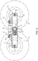
figure 2 , the supportingdevice 15 has a first supportingelement 16, which supports one of the twocentral wheels 3c; and a second supportingelement 17, which supports another one of the twocentral wheels 3c; and wherein the first supportingelement 16 and the second supportingelement 17 are connected to one another through a first articulatedjoint 18 in afirst point 19. The first articulatedjoint 18 preferably is a hinge. - Furthermore, the first and the second supporting
element points 21 that are different from thepoint 19. More in detail, the supportingdevice 15 comprises theshock absorber 20, which is connected to the first and to the second element by means of articulatedjoints 22 placed in thepoints 21, in particular two articulatedjoints 22 in the twopoints 21. The articulatedjoints 22 preferably are hinges. - In a preferred embodiment, the shock absorber 20 has a variable stiffness.
- In another preferred embodiment, the
shock absorber 20 has a variable geometry. - In another preferred embodiment, the
shock absorber 20 has a variable stiffness and a variable geometry. - Furthermore, the shock absorber (20) is mechanical and/or hydraulic and/or electromagnetic and/or an air suspension or any combination thereof.
- More in detail, the supporting
device 15 comprises a connection articulated joint 123, which is partly housed on the first supportingelement 16 and is coupled to theframe 2 so as to couple the supportingdevice 15 to theframe 2 in an articulated manner. The articulated joint 123 preferably is a hinge. - The
central wheels 3c are supporting wheels, in particular they are free rotating wheels. Furthermore, thecentral wheels 3c are middle wheels, which are placed between thefront wheel 3a and therear wheel 3b. - With reference to
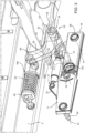
figure 3 , eachshock absorber assembly 160 comprises a mechanical connection arranged between theframe 2 and the supportingdevice 15. The mechanical connection comprises a double-actinghydraulic cylinder 23, a crank 24 and aplate 25 supporting thecrank 24. Thesupport device 15 comprises twoattachments 26 for the two respectivecentral wheels 3c around two rotation axes A1, which are transverse to the axis A (figure 1 ). Thecrank 24 comprises ashaft 27 with axis A2, which is parallel to the axes A1 and is mounted so as to rotate around the axis A2 in thesupport plate 25 fixed to theframe 2; anarm 29, which is integral to theshaft 27 and is mounted so as to rotate, at an end of thehydraulic cylinder 23, around an axis A4, which is parallel to the axes A1. - The
hydraulic cylinder 23 has a first end fixed to theframe 2 so as to rotate around an axis A5, which is parallel to the axes A1. In this way, by changing the length of thehydraulic cylinder 23, it is possible to change the distance of the supportingdevice 15 from theframe 2 or, even better, the distance of the axis A2 from theframe 2, because the supportingdevice 15 can freely oscillate around the axis A2 and, hence, change the position of the respectivecentral wheels 3 relative to theframe 2. - The
control assembly 5 comprises a control unit 13 and the user interface 7 and has the function of acquiring a signal indicating an operating state of the crawledvehicle 1 as a function of at least one operating parameter of the crawled vehicle and, preferably, of a plurality of operating parameters, as well as the function of adjusting the configurations of thewheel assemblies 3 as a function of the signal indicating the operating state, in particular the function of adjusting the configuration and/or the stiffness of theshock absorber assemblies 160. - In a preferred, though non-limiting embodiment of the invention, the control units 13, through the signal indicating the operating state, controls the
shock absorbers 20 one by one or jointly. - In particular, through a manual mode, the driver controls both the position and the stiffness of the
shock absorber assembly 160 and/or of each shock absorber or of allshock absorbers 20 through the support of the displaying on the user interface 7. - In an alternative embodiment of the invention and with reference to
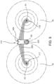
figure 5 , the supportingdevice 15 is replaced by a supportingdevice 115. The supportingdevice 115 comprises anelastic structure 225, in particular a leaf spring, as well as a first supportingelement 116 and a second supportingelement 117, which are arranged at respective ends of theelastic structure 225, in particular of the leaf spring, where two respectivecentral wheels 3c are connected and supported. In the embodiment offigure 5 , the ends of thespring leas 225 define the first and the second supportingelement central wheels 3c. - Furthermore, the supporting
device 115, similarly to the supportingdevice 15, comprises a connection articulated joint 223, which is connected to theelastic structure 225 by means of aconnection element 226. The connection articulated joint 223 is coupled to theframe 2 so as to couple the supportingdevice 115 to theframe 2 in an articulated manner. The articulated joint 223 preferably is a hinge. In this embodiment, theelastic structure 225 allows thecentral wheels 3c to make movements in the range of 60 mm around the balance position, preferably 20 mm around the balance position. Furthermore, the invention evidently also covers embodiments that are not described in the detailed description above as well as embodiments that are part of the scope of protection set forth in the appended claims.
Claims (12)
- Ski pistes preparation crawled vehicle; the crawled vehicle (1) comprising:- a frame (2);- two wheels assemblies (3) displaced at opposite side with respect to the frame (2);- two crawls (4), each of them wounded respectively around to one of the two wheels assemblies (3);- at least one supporting device (15; 115), for each wheels assemblies (3), coupled to at least two wheels (3c) of the wheels assembly (3) and connected in an articulated jointed manner to the frame (2) for coupling the at least two wheels (3c) of the wheels assembly (3) to the frame (2); wherein the supporting device (15; 115) has a first supporting element (16; 116), which supports one of the at least two wheels (3c) of the wheels assembly (3); and a second supporting element (17; 117), which supports another of the two wheels (3c) of the wheels assembly (3); and wherein the first supporting element (16; 116) and the second supporting element (17; 117) are connected between them in an elastically flexible manner or through a first articulated joint (18) in a first point (19); preferably first articulated joint (18) is a hinge;- wherein the wheels assembly (3) comprises a driving wheel (3b), that is a rear wheel;- wherein the wheels assembly (3) comprises a regulating crawl wheel (3a), that is a front wheel, having a mobile position with respect to the frame (2) to stretch the crawl (4);- wherein the at least two wheels (3c) are middle wheels between the regulating crawl wheel (3a) and the driving wheel (3b) and preferably are free rotating wheels.
- Crawled vehicle according to claim 1; wherein the first supporting element (116) and the second supporting element (117) are connected between them through an elastic structure (225), in particular a leaf spring, a fiberglass structure, or a carbon structure.
- Crawled vehicle according to claim 1 or 2; wherein the supporting device (115) comprises an elastic structure (225), in particular a leaf spring, a fiberglass structure, or a carbon structure; the first supporting element (116) and the second supporting element (117), in particular the first supporting element (116) and the second supporting element (117) are defined by respective portions or by respective ends of the elastic structure, in particular by respective portions or ends of the leaf spring or fiber glass structure or carbon structure.
- Crawled vehicle according to claim 1, comprising at least a further articulated joint (22) to couple the first supporting element (16) with the second supporting element (17) in an articulated jointed manner, preferably the further articulated joint (22) is a hinge.
- Crawled vehicle according to claim 1 or 4, wherein the first and the second supporting element (16, 17) are connected between them through a shock absorber (20) in particular in an at least a second point (21) different from the first point (19).
- Crawled vehicle according to claim 5, wherein the shock absorber (20) has a variable stiffness and/or a variable geometry.
- Crawled vehicle according to claim 5 or 6, wherein the shock absorber (20) is of mechanic type and/or hydraulic type and/or electromagnetic type and/or an air suspension type or anyone combination of said type.
- Crawled vehicle according to anyone of the foregoing claims, wherein the supporting device (15) comprises a connection articulated joint (123; 223) coupled to the frame (2) to couple in an articulated jointed manner the supporting device (15; 115) to the frame (2); preferably the articulated connection joint (123; 223) is a hinge.
- Crawled vehicle according to anyone of the foregoing claims, wherein the at least two wheels (3c) of the wheels assembly (3) are supporting wheel in particular free rotating wheel.
- Crawled vehicle according to anyone of the foregoing claims, wherein the supporting device (15) is connected to the frame (2) through a shock absorber assembly (160) .
- Crawled vehicle according to claim 10, wherein the shock absorber assembly (160) has a variable stiffness and/or a variable geometry; in particular the shock absorber assembly (160) comprises a hydraulic cylinder (23) preferably a double effect type.
- Crawled vehicle according to anyone of the foregoing claims, wherein each wheels assembly (3) comprises a regulating crawl wheel (3a) preferably a front wheel; a driving wheel (3b) preferably a rear wheel; two couple of supporting wheel (3c) and two supporting device (15; 115), each of them coupled to one respectively couple of supporting wheels (3c).
Applications Claiming Priority (2)
| Application Number | Priority Date | Filing Date | Title |
|---|---|---|---|
| IT102018000003244A IT201800003244A1 (en) | 2018-03-02 | 2018-03-02 | TRACKED VEHICLE FOR THE PREPARATION OF SKI SLOPES |
| PCT/IB2019/051676 WO2019167020A1 (en) | 2018-03-02 | 2019-03-01 | Crawled vehicle for the preparation of ski pistes |
Publications (3)
| Publication Number | Publication Date |
|---|---|
| EP3759014A1 EP3759014A1 (en) | 2021-01-06 |
| EP3759014C0 EP3759014C0 (en) | 2023-11-01 |
| EP3759014B1 true EP3759014B1 (en) | 2023-11-01 |
Family
ID=62386732
Family Applications (1)
| Application Number | Title | Priority Date | Filing Date |
|---|---|---|---|
| EP19712628.7A Active EP3759014B1 (en) | 2018-03-02 | 2019-03-01 | Crawled vehicle for the preparation of ski pistes |
Country Status (6)
| Country | Link |
|---|---|
| US (1) | US20210001934A1 (en) |
| EP (1) | EP3759014B1 (en) |
| CN (1) | CN110217302B (en) |
| CA (1) | CA3092550A1 (en) |
| IT (1) | IT201800003244A1 (en) |
| WO (1) | WO2019167020A1 (en) |
Families Citing this family (2)
| Publication number | Priority date | Publication date | Assignee | Title |
|---|---|---|---|---|
| SE542243C2 (en) * | 2017-03-17 | 2020-03-24 | Komatsu Forest Ab | Suspension device for tracked vehicles |
| IT201800003244A1 (en) | 2018-03-02 | 2019-09-02 | Prinoth Spa | TRACKED VEHICLE FOR THE PREPARATION OF SKI SLOPES |
Citations (9)
| Publication number | Priority date | Publication date | Assignee | Title |
|---|---|---|---|---|
| US1386926A (en) * | 1920-09-03 | 1921-08-09 | Krupp Ag | Endless-track arrangement for vehicles |
| US3285676A (en) | 1964-10-28 | 1966-11-15 | Polaris Inc | Rubber track |
| EP0352163B1 (en) * | 1988-07-12 | 1992-09-09 | S.A.M.M.- Société d'Applications des Machines Motrices | Load suspension providing springing and damping, especially for a vehicle |
| EP1318067A2 (en) | 2001-12-07 | 2003-06-11 | Kässbohrer Geländefahrzeug AG | Track for a crawler vehicle |
| DE102004059823A1 (en) | 2004-12-03 | 2006-06-08 | Kässbohrer Geländefahrzeug AG | Tracked vehicle for ski slope, has support arm connected with end of spring that is supported in frame, and adjusting unit provided at distance from support arm, where adjusting unit changes turning position of spring to frame in sections |
| EP3222500A1 (en) | 2016-03-24 | 2017-09-27 | Kässbohrer Geländefahrzeug AG | Chain drive and civil tracked vehicle |
| WO2018024766A2 (en) * | 2016-08-02 | 2018-02-08 | Cnh Industrial Italia S.P.A. | Track system for a work vehicle |
| WO2018024762A2 (en) | 2016-08-02 | 2018-02-08 | Cnh Industrial Italia S.P.A. | Track system for a work vehicle |
| WO2019167020A1 (en) | 2018-03-02 | 2019-09-06 | Prinoth S.P.A. | Crawled vehicle for the preparation of ski pistes |
Family Cites Families (10)
| Publication number | Priority date | Publication date | Assignee | Title |
|---|---|---|---|---|
| US1744229A (en) * | 1924-08-27 | 1930-01-21 | Harry A Knox | Suspension for tracklaying vehicles |
| GB573265A (en) * | 1943-12-31 | 1945-11-13 | Vivian Loyd & Company | Improvements in or relating to articulated bogies for track laying or other vehicles |
| DD278562A1 (en) * | 1988-12-23 | 1990-05-09 | Fzm Schlieben | TRACK SUSPENSION BAND |
| US6321864B1 (en) * | 2000-04-27 | 2001-11-27 | Vernal D. Forbes | Snow vehicle track suspension |
| CA2346574C (en) * | 2001-05-07 | 2008-11-04 | Tri-Track International Ltd. | Snow or soil grader |
| US6810975B2 (en) * | 2002-05-23 | 2004-11-02 | Westerngaco A.S. | Suspension system for a tracked vehicle |
| CN101472784B (en) * | 2006-06-08 | 2012-09-26 | R·麦肯齐 | Snow Traction Units for Vehicles |
| CN104691640A (en) * | 2013-12-10 | 2015-06-10 | 明光市浩淼消防科技发展有限公司 | Landing buffer device |
| ITMI20132179A1 (en) * | 2013-12-20 | 2015-06-21 | Snowgrolic S A R L | SUPPORT DEVICE FOR A TRACKED VEHICLE AND TRACKED VEHICLE INCLUDING SUCH SUPPORT DEVICE |
| IT201600081200A1 (en) * | 2016-08-02 | 2018-02-02 | Cnh Ind Italia Spa | TRACK SYSTEM FOR WORKING VEHICLE |
-
2018
- 2018-03-02 IT IT102018000003244A patent/IT201800003244A1/en unknown
-
2019
- 2019-03-01 US US16/976,956 patent/US20210001934A1/en not_active Abandoned
- 2019-03-01 CA CA3092550A patent/CA3092550A1/en active Pending
- 2019-03-01 WO PCT/IB2019/051676 patent/WO2019167020A1/en not_active Ceased
- 2019-03-01 EP EP19712628.7A patent/EP3759014B1/en active Active
- 2019-03-04 CN CN201910160462.2A patent/CN110217302B/en not_active Expired - Fee Related
Patent Citations (9)
| Publication number | Priority date | Publication date | Assignee | Title |
|---|---|---|---|---|
| US1386926A (en) * | 1920-09-03 | 1921-08-09 | Krupp Ag | Endless-track arrangement for vehicles |
| US3285676A (en) | 1964-10-28 | 1966-11-15 | Polaris Inc | Rubber track |
| EP0352163B1 (en) * | 1988-07-12 | 1992-09-09 | S.A.M.M.- Société d'Applications des Machines Motrices | Load suspension providing springing and damping, especially for a vehicle |
| EP1318067A2 (en) | 2001-12-07 | 2003-06-11 | Kässbohrer Geländefahrzeug AG | Track for a crawler vehicle |
| DE102004059823A1 (en) | 2004-12-03 | 2006-06-08 | Kässbohrer Geländefahrzeug AG | Tracked vehicle for ski slope, has support arm connected with end of spring that is supported in frame, and adjusting unit provided at distance from support arm, where adjusting unit changes turning position of spring to frame in sections |
| EP3222500A1 (en) | 2016-03-24 | 2017-09-27 | Kässbohrer Geländefahrzeug AG | Chain drive and civil tracked vehicle |
| WO2018024766A2 (en) * | 2016-08-02 | 2018-02-08 | Cnh Industrial Italia S.P.A. | Track system for a work vehicle |
| WO2018024762A2 (en) | 2016-08-02 | 2018-02-08 | Cnh Industrial Italia S.P.A. | Track system for a work vehicle |
| WO2019167020A1 (en) | 2018-03-02 | 2019-09-06 | Prinoth S.P.A. | Crawled vehicle for the preparation of ski pistes |
Also Published As
| Publication number | Publication date |
|---|---|
| EP3759014A1 (en) | 2021-01-06 |
| WO2019167020A1 (en) | 2019-09-06 |
| CN110217302B (en) | 2023-07-18 |
| EP3759014C0 (en) | 2023-11-01 |
| US20210001934A1 (en) | 2021-01-07 |
| CA3092550A1 (en) | 2019-09-06 |
| CN110217302A (en) | 2019-09-10 |
| IT201800003244A1 (en) | 2019-09-02 |
Similar Documents
| Publication | Publication Date | Title |
|---|---|---|
| KR100933650B1 (en) | In-wheel suspension | |
| EP3248818B1 (en) | Independent suspension with multiple supporting points | |
| EP3984862B1 (en) | Motor-vehicle with driving and steering rear wheels | |
| JP6091788B2 (en) | Active roll control device | |
| EP3759014B1 (en) | Crawled vehicle for the preparation of ski pistes | |
| JP6371383B2 (en) | Steerable wheel suspension | |
| KR20240043826A (en) | Suspension Apparatus for vehicle | |
| JP4922922B2 (en) | Seat suspension system | |
| JP2009509845A (en) | Vehicle suspension system | |
| US7866681B1 (en) | Self-guided air spring assembly | |
| CN106739919B (en) | Anti-roll system for vehicle and vehicle | |
| US20120193941A1 (en) | Utility Vehicle Cab Suspension | |
| EP3666561B1 (en) | Suspension for a steerable wheel of a motor vehicle | |
| SE531928C2 (en) | Cab suspension device and cab suspension | |
| JP2010513115A (en) | Wheel suspension | |
| JP2017001407A (en) | Suspension structure for in-wheel motor drive device | |
| EP1707408B1 (en) | Vehicle suspension systems | |
| CN113811455B (en) | suspension device | |
| CN114633594B (en) | Suspension system for vehicle and vehicle | |
| US20250010681A1 (en) | Suspension for a motor vehicle | |
| CN111038608A (en) | Tracked vehicle for preparing ski runs | |
| CN117184301A (en) | All-terrain vehicle | |
| JP5033007B2 (en) | Working vehicle traveling device | |
| CN117184299A (en) | All-terrain vehicle | |
| KR100962203B1 (en) | Strut suspension |
Legal Events
| Date | Code | Title | Description |
|---|---|---|---|
| STAA | Information on the status of an ep patent application or granted ep patent |
Free format text: STATUS: UNKNOWN |
|
| STAA | Information on the status of an ep patent application or granted ep patent |
Free format text: STATUS: THE INTERNATIONAL PUBLICATION HAS BEEN MADE |
|
| PUAI | Public reference made under article 153(3) epc to a published international application that has entered the european phase |
Free format text: ORIGINAL CODE: 0009012 |
|
| STAA | Information on the status of an ep patent application or granted ep patent |
Free format text: STATUS: REQUEST FOR EXAMINATION WAS MADE |
|
| 17P | Request for examination filed |
Effective date: 20200916 |
|
| AK | Designated contracting states |
Kind code of ref document: A1 Designated state(s): AL AT BE BG CH CY CZ DE DK EE ES FI FR GB GR HR HU IE IS IT LI LT LU LV MC MK MT NL NO PL PT RO RS SE SI SK SM TR |
|
| AX | Request for extension of the european patent |
Extension state: BA ME |
|
| DAV | Request for validation of the european patent (deleted) | ||
| DAX | Request for extension of the european patent (deleted) | ||
| GRAP | Despatch of communication of intention to grant a patent |
Free format text: ORIGINAL CODE: EPIDOSNIGR1 |
|
| STAA | Information on the status of an ep patent application or granted ep patent |
Free format text: STATUS: GRANT OF PATENT IS INTENDED |
|
| INTG | Intention to grant announced |
Effective date: 20230525 |
|
| P01 | Opt-out of the competence of the unified patent court (upc) registered |
Effective date: 20230518 |
|
| GRAS | Grant fee paid |
Free format text: ORIGINAL CODE: EPIDOSNIGR3 |
|
| GRAA | (expected) grant |
Free format text: ORIGINAL CODE: 0009210 |
|
| STAA | Information on the status of an ep patent application or granted ep patent |
Free format text: STATUS: THE PATENT HAS BEEN GRANTED |
|
| AK | Designated contracting states |
Kind code of ref document: B1 Designated state(s): AL AT BE BG CH CY CZ DE DK EE ES FI FR GB GR HR HU IE IS IT LI LT LU LV MC MK MT NL NO PL PT RO RS SE SI SK SM TR |
|
| REG | Reference to a national code |
Ref country code: GB Ref legal event code: FG4D |
|
| REG | Reference to a national code |
Ref country code: CH Ref legal event code: EP |
|
| REG | Reference to a national code |
Ref country code: IE Ref legal event code: FG4D |
|
| REG | Reference to a national code |
Ref country code: DE Ref legal event code: R096 Ref document number: 602019040519 Country of ref document: DE |
|
| P04 | Withdrawal of opt-out of the competence of the unified patent court (upc) registered |
Effective date: 20231114 |
|
| U01 | Request for unitary effect filed |
Effective date: 20231110 |
|
| U07 | Unitary effect registered |
Designated state(s): AT BE BG DE DK EE FI FR IT LT LU LV MT NL PT SE SI Effective date: 20231117 |
|
| PG25 | Lapsed in a contracting state [announced via postgrant information from national office to epo] |
Ref country code: GR Free format text: LAPSE BECAUSE OF FAILURE TO SUBMIT A TRANSLATION OF THE DESCRIPTION OR TO PAY THE FEE WITHIN THE PRESCRIBED TIME-LIMIT Effective date: 20240202 |
|
| PG25 | Lapsed in a contracting state [announced via postgrant information from national office to epo] |
Ref country code: IS Free format text: LAPSE BECAUSE OF FAILURE TO SUBMIT A TRANSLATION OF THE DESCRIPTION OR TO PAY THE FEE WITHIN THE PRESCRIBED TIME-LIMIT Effective date: 20240301 |
|
| U20 | Renewal fee for the european patent with unitary effect paid |
Year of fee payment: 6 Effective date: 20240315 |
|
| PG25 | Lapsed in a contracting state [announced via postgrant information from national office to epo] |
Ref country code: ES Free format text: LAPSE BECAUSE OF FAILURE TO SUBMIT A TRANSLATION OF THE DESCRIPTION OR TO PAY THE FEE WITHIN THE PRESCRIBED TIME-LIMIT Effective date: 20231101 |
|
| PG25 | Lapsed in a contracting state [announced via postgrant information from national office to epo] |
Ref country code: IS Free format text: LAPSE BECAUSE OF FAILURE TO SUBMIT A TRANSLATION OF THE DESCRIPTION OR TO PAY THE FEE WITHIN THE PRESCRIBED TIME-LIMIT Effective date: 20240301 Ref country code: GR Free format text: LAPSE BECAUSE OF FAILURE TO SUBMIT A TRANSLATION OF THE DESCRIPTION OR TO PAY THE FEE WITHIN THE PRESCRIBED TIME-LIMIT Effective date: 20240202 Ref country code: ES Free format text: LAPSE BECAUSE OF FAILURE TO SUBMIT A TRANSLATION OF THE DESCRIPTION OR TO PAY THE FEE WITHIN THE PRESCRIBED TIME-LIMIT Effective date: 20231101 |
|
| PG25 | Lapsed in a contracting state [announced via postgrant information from national office to epo] |
Ref country code: RS Free format text: LAPSE BECAUSE OF FAILURE TO SUBMIT A TRANSLATION OF THE DESCRIPTION OR TO PAY THE FEE WITHIN THE PRESCRIBED TIME-LIMIT Effective date: 20231101 Ref country code: PL Free format text: LAPSE BECAUSE OF FAILURE TO SUBMIT A TRANSLATION OF THE DESCRIPTION OR TO PAY THE FEE WITHIN THE PRESCRIBED TIME-LIMIT Effective date: 20231101 Ref country code: NO Free format text: LAPSE BECAUSE OF FAILURE TO SUBMIT A TRANSLATION OF THE DESCRIPTION OR TO PAY THE FEE WITHIN THE PRESCRIBED TIME-LIMIT Effective date: 20240201 Ref country code: HR Free format text: LAPSE BECAUSE OF FAILURE TO SUBMIT A TRANSLATION OF THE DESCRIPTION OR TO PAY THE FEE WITHIN THE PRESCRIBED TIME-LIMIT Effective date: 20231101 |
|
| PG25 | Lapsed in a contracting state [announced via postgrant information from national office to epo] |
Ref country code: CZ Free format text: LAPSE BECAUSE OF FAILURE TO SUBMIT A TRANSLATION OF THE DESCRIPTION OR TO PAY THE FEE WITHIN THE PRESCRIBED TIME-LIMIT Effective date: 20231101 |
|
| REG | Reference to a national code |
Ref country code: DE Ref legal event code: R026 Ref document number: 602019040519 Country of ref document: DE |
|
| PLBI | Opposition filed |
Free format text: ORIGINAL CODE: 0009260 |
|
| PG25 | Lapsed in a contracting state [announced via postgrant information from national office to epo] |
Ref country code: SK Free format text: LAPSE BECAUSE OF FAILURE TO SUBMIT A TRANSLATION OF THE DESCRIPTION OR TO PAY THE FEE WITHIN THE PRESCRIBED TIME-LIMIT Effective date: 20231101 |
|
| PG25 | Lapsed in a contracting state [announced via postgrant information from national office to epo] |
Ref country code: SM Free format text: LAPSE BECAUSE OF FAILURE TO SUBMIT A TRANSLATION OF THE DESCRIPTION OR TO PAY THE FEE WITHIN THE PRESCRIBED TIME-LIMIT Effective date: 20231101 Ref country code: SK Free format text: LAPSE BECAUSE OF FAILURE TO SUBMIT A TRANSLATION OF THE DESCRIPTION OR TO PAY THE FEE WITHIN THE PRESCRIBED TIME-LIMIT Effective date: 20231101 Ref country code: CZ Free format text: LAPSE BECAUSE OF FAILURE TO SUBMIT A TRANSLATION OF THE DESCRIPTION OR TO PAY THE FEE WITHIN THE PRESCRIBED TIME-LIMIT Effective date: 20231101 |
|
| PLAX | Notice of opposition and request to file observation + time limit sent |
Free format text: ORIGINAL CODE: EPIDOSNOBS2 |
|
| 26 | Opposition filed |
Opponent name: KAESSBOHRER GELAENDEFAHRZEUG AG Effective date: 20240724 |
|
| PG25 | Lapsed in a contracting state [announced via postgrant information from national office to epo] |
Ref country code: MC Free format text: LAPSE BECAUSE OF FAILURE TO SUBMIT A TRANSLATION OF THE DESCRIPTION OR TO PAY THE FEE WITHIN THE PRESCRIBED TIME-LIMIT Effective date: 20231101 |
|
| GBPC | Gb: european patent ceased through non-payment of renewal fee |
Effective date: 20240301 |
|
| PG25 | Lapsed in a contracting state [announced via postgrant information from national office to epo] |
Ref country code: MC Free format text: LAPSE BECAUSE OF FAILURE TO SUBMIT A TRANSLATION OF THE DESCRIPTION OR TO PAY THE FEE WITHIN THE PRESCRIBED TIME-LIMIT Effective date: 20231101 |
|
| PLBB | Reply of patent proprietor to notice(s) of opposition received |
Free format text: ORIGINAL CODE: EPIDOSNOBS3 |
|
| P05 | Withdrawal of opt-out of the competence of the unified patent court (upc) changed |
Free format text: CASE NUMBER: APP_587215/2023 Effective date: 20231117 |
|
| PG25 | Lapsed in a contracting state [announced via postgrant information from national office to epo] |
Ref country code: GB Free format text: LAPSE BECAUSE OF NON-PAYMENT OF DUE FEES Effective date: 20240301 |
|
| PG25 | Lapsed in a contracting state [announced via postgrant information from national office to epo] |
Ref country code: IE Free format text: LAPSE BECAUSE OF NON-PAYMENT OF DUE FEES Effective date: 20240301 |
|
| PG25 | Lapsed in a contracting state [announced via postgrant information from national office to epo] |
Ref country code: IE Free format text: LAPSE BECAUSE OF NON-PAYMENT OF DUE FEES Effective date: 20240301 Ref country code: GB Free format text: LAPSE BECAUSE OF NON-PAYMENT OF DUE FEES Effective date: 20240301 |
|
| U20 | Renewal fee for the european patent with unitary effect paid |
Year of fee payment: 7 Effective date: 20250311 |
|
| PG25 | Lapsed in a contracting state [announced via postgrant information from national office to epo] |
Ref country code: RO Free format text: LAPSE BECAUSE OF FAILURE TO SUBMIT A TRANSLATION OF THE DESCRIPTION OR TO PAY THE FEE WITHIN THE PRESCRIBED TIME-LIMIT Effective date: 20231101 |
|
| PGFP | Annual fee paid to national office [announced via postgrant information from national office to epo] |
Ref country code: CH Payment date: 20250401 Year of fee payment: 7 |
|
| PG25 | Lapsed in a contracting state [announced via postgrant information from national office to epo] |
Ref country code: CY Free format text: LAPSE BECAUSE OF FAILURE TO SUBMIT A TRANSLATION OF THE DESCRIPTION OR TO PAY THE FEE WITHIN THE PRESCRIBED TIME-LIMIT; INVALID AB INITIO Effective date: 20190301 |
|
| PG25 | Lapsed in a contracting state [announced via postgrant information from national office to epo] |
Ref country code: HU Free format text: LAPSE BECAUSE OF FAILURE TO SUBMIT A TRANSLATION OF THE DESCRIPTION OR TO PAY THE FEE WITHIN THE PRESCRIBED TIME-LIMIT; INVALID AB INITIO Effective date: 20190301 |
|
| PG25 | Lapsed in a contracting state [announced via postgrant information from national office to epo] |
Ref country code: TR Free format text: LAPSE BECAUSE OF FAILURE TO SUBMIT A TRANSLATION OF THE DESCRIPTION OR TO PAY THE FEE WITHIN THE PRESCRIBED TIME-LIMIT Effective date: 20231101 |
|
| APAH | Appeal reference modified |
Free format text: ORIGINAL CODE: EPIDOSCREFNO |
|
| APAW | Appeal reference deleted |
Free format text: ORIGINAL CODE: EPIDOSDREFNO |
|
| APBP | Date of receipt of notice of appeal recorded |
Free format text: ORIGINAL CODE: EPIDOSNNOA2O |