EP3759003B1 - Engine friction monitor - Google Patents
Engine friction monitor Download PDFInfo
- Publication number
- EP3759003B1 EP3759003B1 EP19781246.4A EP19781246A EP3759003B1 EP 3759003 B1 EP3759003 B1 EP 3759003B1 EP 19781246 A EP19781246 A EP 19781246A EP 3759003 B1 EP3759003 B1 EP 3759003B1
- Authority
- EP
- European Patent Office
- Prior art keywords
- torque
- engine
- error
- threshold boundary
- area
- Prior art date
- Legal status (The legal status is an assumption and is not a legal conclusion. Google has not performed a legal analysis and makes no representation as to the accuracy of the status listed.)
- Active
Links
Images




Classifications
-
- B—PERFORMING OPERATIONS; TRANSPORTING
- B60—VEHICLES IN GENERAL
- B60W—CONJOINT CONTROL OF VEHICLE SUB-UNITS OF DIFFERENT TYPE OR DIFFERENT FUNCTION; CONTROL SYSTEMS SPECIALLY ADAPTED FOR HYBRID VEHICLES; ROAD VEHICLE DRIVE CONTROL SYSTEMS FOR PURPOSES NOT RELATED TO THE CONTROL OF A PARTICULAR SUB-UNIT
- B60W50/00—Details of control systems for road vehicle drive control not related to the control of a particular sub-unit, e.g. process diagnostic or vehicle driver interfaces
- B60W50/02—Ensuring safety in case of control system failures, e.g. by diagnosing, circumventing or fixing failures
- B60W50/038—Limiting the input power, torque or speed
-
- F—MECHANICAL ENGINEERING; LIGHTING; HEATING; WEAPONS; BLASTING
- F02—COMBUSTION ENGINES; HOT-GAS OR COMBUSTION-PRODUCT ENGINE PLANTS
- F02D—CONTROLLING COMBUSTION ENGINES
- F02D41/00—Electrical control of supply of combustible mixture or its constituents
- F02D41/22—Safety or indicating devices for abnormal conditions
-
- B—PERFORMING OPERATIONS; TRANSPORTING
- B60—VEHICLES IN GENERAL
- B60W—CONJOINT CONTROL OF VEHICLE SUB-UNITS OF DIFFERENT TYPE OR DIFFERENT FUNCTION; CONTROL SYSTEMS SPECIALLY ADAPTED FOR HYBRID VEHICLES; ROAD VEHICLE DRIVE CONTROL SYSTEMS FOR PURPOSES NOT RELATED TO THE CONTROL OF A PARTICULAR SUB-UNIT
- B60W20/00—Control systems specially adapted for hybrid vehicles
- B60W20/50—Control strategies for responding to system failures, e.g. for fault diagnosis, failsafe operation or limp mode
-
- F—MECHANICAL ENGINEERING; LIGHTING; HEATING; WEAPONS; BLASTING
- F02—COMBUSTION ENGINES; HOT-GAS OR COMBUSTION-PRODUCT ENGINE PLANTS
- F02D—CONTROLLING COMBUSTION ENGINES
- F02D41/00—Electrical control of supply of combustible mixture or its constituents
- F02D41/02—Circuit arrangements for generating control signals
- F02D41/14—Introducing closed-loop corrections
- F02D41/1497—With detection of the mechanical response of the engine
-
- B—PERFORMING OPERATIONS; TRANSPORTING
- B60—VEHICLES IN GENERAL
- B60W—CONJOINT CONTROL OF VEHICLE SUB-UNITS OF DIFFERENT TYPE OR DIFFERENT FUNCTION; CONTROL SYSTEMS SPECIALLY ADAPTED FOR HYBRID VEHICLES; ROAD VEHICLE DRIVE CONTROL SYSTEMS FOR PURPOSES NOT RELATED TO THE CONTROL OF A PARTICULAR SUB-UNIT
- B60W2710/00—Output or target parameters relating to a particular sub-units
- B60W2710/08—Electric propulsion units
- B60W2710/083—Torque
-
- F—MECHANICAL ENGINEERING; LIGHTING; HEATING; WEAPONS; BLASTING
- F02—COMBUSTION ENGINES; HOT-GAS OR COMBUSTION-PRODUCT ENGINE PLANTS
- F02D—CONTROLLING COMBUSTION ENGINES
- F02D2200/00—Input parameters for engine control
- F02D2200/02—Input parameters for engine control the parameters being related to the engine
- F02D2200/10—Parameters related to the engine output, e.g. engine torque or engine speed
- F02D2200/1002—Output torque
-
- F—MECHANICAL ENGINEERING; LIGHTING; HEATING; WEAPONS; BLASTING
- F02—COMBUSTION ENGINES; HOT-GAS OR COMBUSTION-PRODUCT ENGINE PLANTS
- F02D—CONTROLLING COMBUSTION ENGINES
- F02D2200/00—Input parameters for engine control
- F02D2200/02—Input parameters for engine control the parameters being related to the engine
- F02D2200/10—Parameters related to the engine output, e.g. engine torque or engine speed
- F02D2200/1006—Engine torque losses, e.g. friction or pumping losses or losses caused by external loads of accessories
-
- F—MECHANICAL ENGINEERING; LIGHTING; HEATING; WEAPONS; BLASTING
- F02—COMBUSTION ENGINES; HOT-GAS OR COMBUSTION-PRODUCT ENGINE PLANTS
- F02D—CONTROLLING COMBUSTION ENGINES
- F02D2250/00—Engine control related to specific problems or objectives
- F02D2250/18—Control of the engine output torque
-
- F—MECHANICAL ENGINEERING; LIGHTING; HEATING; WEAPONS; BLASTING
- F02—COMBUSTION ENGINES; HOT-GAS OR COMBUSTION-PRODUCT ENGINE PLANTS
- F02D—CONTROLLING COMBUSTION ENGINES
- F02D41/00—Electrical control of supply of combustible mixture or its constituents
- F02D41/24—Electrical control of supply of combustible mixture or its constituents characterised by the use of digital means
- F02D41/2406—Electrical control of supply of combustible mixture or its constituents characterised by the use of digital means using essentially read only memories
- F02D41/2425—Particular ways of programming the data
- F02D41/2429—Methods of calibrating or learning
Definitions
- the present invention relates generally to an identification of a potential or impending failure of an engine and/or one or more engine components.
- US 2012/253631 A1 relates to an engine powered wheeled machine having improved engine over speed and under speed protection. It includes a parallel path transmission having a gear train with first and second transmission inputs and a transmission output, and includes a hydraulic variator having a variator output driving the first transmission input, the hydraulic variator having a variator pump and a variator motor, the displacement of the variator pump being controlled by a variator actuator.
- the machine further includes an engine having an engine output driving the second transmission input and driving the variator pump and a controller for receiving one or more values indicative of one or more ranges of permissible engine speed, a value indicative of an actual engine speed, and a value indicative of the position of the variator actuator, with the controller being configured to control the position of the variator actuator based on state space gain mapping to maintain the engine speed within the one or more ranges of permissible engine speed.
- the present invention describes an engine friction monitor that uses commanded torque and measured torque to provide a prognostic feature to identify potential failure of an engine and/or its components that causes the engine to be prevented from delivering the commanded torque.
- the invention provides a method for monitoring engine friction according to claim 1 and a system for monitoring engine friction according to claim 6.
- the present invention is applicable to any engine capable of converting various types of energy into mechanical force and motion, and further applicable to any engine control module for commanding a rotational force (i.e., torque) to be produced by an engine.
- the present invention describes an engine friction monitor system and method that uses commanded torque and measured torque, rate of change of torque, pattern recognition, and classification methods to provide a prognostic feature to identify potential failure of an engine that causes the engine from delivering the commanded torque due to an increase in friction on the engine components.
- FIG. 1 shows an engine friction learning module 10 of the present invention for baselining to learn behavior of a nominal, good engine system and provide confidence in the baseline models.
- Engine friction module 10 may provide data filtering and selection to extract the correct information to make decisions and classify the data to determine if the system is operating in a "good” condition or "bad” condition.
- a "good” condition indicates a torque deviation of the engine from a commanded torque that is within one or more predetermined thresholds, i.e. that the engine friction amount is acceptable or within tolerances.
- a "bad” system indicates a torque deviation that is more than one or more thresholds indicative of an excessive friction condition for one or more components of the engine, i.e. that the engine friction amount is unacceptable or outside tolerances.
- Engine friction learning module 10 can include, for example, a computer module or circuit configured for processing a commanded torque CT OE and a measured torque MT OE from operational engine(s) and further process a commanded torque CT FE and a measured torque MT FE from failed engine(s) to generate a plotted error space 20P. This data is used to learn the plotted error space 20P, which is modified with subsequent data to learn a baseline error space 20B.
- a torque error is a differential between a commanded torque and a measured torque of a particular engine, such as, for this present invention, a differential between commanded torque CT OE and measured torque MT OE from an operational engine or a differential between commanded torque CT FE and measured torque MT FE from a failed engine.
- Slope error is determined in response to a differential between a rate of change of the commanded torque and a rate of change of the measured torque.
- Plotted error space 20P includes a nominal threshold boundary 25P dividing plotted error space 20P into a "good” torque area 26P of plotted torque errors 23P between commanded torque CT OE and measured torque MT OE from operational engines and a "bad" torque area 27P of plotted torque errors 24P between commanded torque CT FE and measured torque MT FE from failed engines.
- Plotted error space 20P trains the engine friction learning module 10 to learn how the nominal system performs and produce a nominal threshold boundary based on initial data.
- torque errors between commanded torque CT OE and measured torque MT OE are classified as good torque errors 21G below nominal threshold boundary 25P on torque error axis 21 from operational engines.
- Torque errors between commanded torque CT FE and measured torque MT FE from failed engines above nominal threshold boundary 25P on torque error axis 21 are classified as bad torque errors 21B.
- Slope or rate of change errors are initially classified as good slope errors 22G below nominal threshold boundary 25P on slope error axis 22 from operational engines, and bad slope errors 22B from failed engines if above nominal threshold boundary 25P on slope error axis 22.
- baseline error space 20B includes plotted good torque errors 23P and plotted bad torque errors 24P that are baselined relative to an origin of plotted error space 20P to identify the nominal or initial behavior of the engine represented by nominal threshold boundary 25P.
- engine friction learning module 10 computes a cumulative sum of the distances of the points from the origin of plotted error space 20P. This ensures points that are further away from the nominal threshold boundary 25P and are added to the "bad" area get weighted higher to provide appropriate weight to failures that cause significant impact on increased friction.
- the plotted nominal threshold boundary 25P evolves into baseline threshold boundary 25B over time as more data is collected.
- Baseline torque error space 20B includes good torque errors 23B below baseline threshold boundary 25B and bad torque errors 24B above baseline threshold boundary 25B.
- Baseline threshold boundary 25B divides baseline torque error space 20B into good torque area 26B and bad torque area 27B.
- torque errors are initially classified as good torque errors 21G' below baseline threshold boundary 25B on torque error axis 21 from operational engines, and bad torque errors 21B' from failed engines above baseline threshold boundary 25B on torque error axis 21.
- Slope or rate of change errors are initially classified as good slope errors 22G' below baseline threshold boundary 25B on slope error axis 22 from operational engines, and bad slope errors 22B' from failed engines above baseline threshold boundary 25B on slope error axis 22.
- Engine friction learning module 10 outputs a monitoring error space 20M in FIG. 3 for monitoring an engine in real-time to thereby identify any failure modes of the engine that causes the engine from delivering commanded torque.
- Monitoring error space 20M is defined by torque error axis 21 and slope error axis 22 and includes a monitoring baseline threshold boundary 25H, 25I, or 25L to divide monitoring error space 20M into a first, good torque area below the monitoring baseline threshold boundary 25H, 25I, or 25L and a second, bad torque area above monitoring baseline threshold boundary 25H, 25I, or 25L.
- baseline threshold boundary 25B ( FIG. 1 ) serves as the initial high confidence monitoring threshold boundary 25H for dividing the first and second torque areas and can be shifted based on a change in a confidence level of the torque data.
- engine friction learning module 10 establishes a confidence level in engine conditions being utilized for learning including, but not limited to, how much torque data is being provided and a degree of variation of the torque data.
- engine friction learning module 10 trains nominal threshold boundary 25P as previously described, engine friction learning module 10 can establish a low confidence threshold boundary 25L reflective of a low confidence level in the conditions being conducive for predicting the impact of friction on the torque output, an intermediate threshold boundary 25I reflective of an intermediate confidence level in the engine conditions being conducive for prediction, and a high confidence threshold boundary 25H reflective of a high confidence level in the engine conditions being conducive for predicting the impact of friction on the torque output.
- Engine friction learning module 10 may thereby control the classification of data as "good” or "bad” based on the assigned confidence level for the predictive value of the data that is collected.
- engine friction learning module 10 may stay at high confidence threshold boundary 25H until such time the engine experiences operating conditions that provide less confidence being utilized for learning or predicting the impact due to engine friction (due to lack of information, too much variation, movement to a different load point, a key off event, etc.), the threshold boundary can transition 28I to intermediate confidence threshold boundary 25I.
- the confidence level can also transition 28C to a low confidence level 28L depending on the operating conditions.
- the learning can be reset through a service tool if needed. The resetting of the confidence level allows the thresholds to be revisited and ensure more robustness in predictions and reduce the impact of uncertainty and new conditions on the prediction method.
- an engine friction monitor 50 of the present invention executes an engine friction monitoring method or procedure 60 embodied by a flow diagram.
- engine friction monitor 50 processes torque of an engine 30 commanded and measured by ECM 31 to identify potential failure modes of engine 30 that causes the engine from being prevented in delivering the commanded torque.
- Engine 30 may be any type of engine including, but not limited to, an internal combustion engine.
- engine 30 can be a gasoline engine, diesel engine, natural gas engine, dual fuel engine, or any other type of engine known in the art.
- Engine 30 can be employed in stationary applications, such as in powering a generator set, or in powering a vehicle, pump, or other equipment.
- Engine control module (ECM) 31, monitor enabler 40, torque signal processor 41, and/or engine friction monitor 50 can be implemented in hardware as one or more computer processing modules, circuits, and/or as instructions encoded on computer readable medium, and may be distributed across various hardware, computer processor or controller components or combined in a single controller or computer processor.
- a monitor enabler 40 receives enable condition signals ECS from ECM 31 to communicate an enable signal ES or a disable signal DS to engine friction monitor 50.
- Enable condition signals include, but are not limited to, a signal indicative of whether a circuit breaker is closed or open, whether a load request is present, an engine speed signal, an engine temperature condition, or any other condition that may be suitably required for monitoring of engine friction.
- a torque signal processor 41 is provided to receive commanded torque CT RT and measured torque MT RT in real-time from ECM 31 and applies a transient filtering of the torque to thereby communicate a conditioned commanded torque signal CTsc and conditioned measured torque signal MTsc to another module or circuit, such as a torque baseliner 51 of an enabled engine friction monitor 50.
- Engine friction monitor 50 also includes circuits or modules such as an error calculator 52 and a torque classifier 53 in communication with torque baseliner 51.
- Error calculator 52 determines a torque error TE and slope error SE from torque feedback target FT.
- Torque classifier 53 outputs classification points CP for the current operating conditions in response to the confidence level CL from torque baseliner 51 and the torque error TE and slope error SE from error calculator 52.
- An engine failure predictor 54 includes a module or circuit that receives the operating classification points CP and outputs a failure prediction FP to ECM 31. ECM 31 can then accumulate the indicators and take no action, provide an output such as a warning or alerts to have the engine serviced, and/or derate the engine completely or partially to prevent catastrophic damage or to limit the potential for damage depending on the failure prediction.
- Procedure 60 includes an operation 62 in which torque baseliner 51 baselines conditioned commanded torque signal CTsc and conditioned measured torque signal MTsc in accordance with the training of engine friction monitor 50 as previously described herein.
- torque baseliner 51 determines a confidence level CL and feedback target FT from conditioned commanded torque signal CTsc and conditioned measured torque signal MTsc.
- An operation 66 of procedure 60 includes error calculator 52 calculating a torque error TE and slope error SE based on the feedback target FT.
- Torque classifier 53 plots torque error TE and slope error SE on monitoring error space 20M ( FIG. 3 ) relative to a selected monitoring threshold boundary 25H, 25I, 25L to thereby calculate classification points CP at operation 68, which are accumulated to provide a failure prediction as will be further described herein in connection with FIGS. 6-8 .
- Procedure 60 continues at operation 70 which includes engine failure predictor 54 determining a failure prediction FP based on an accumulation of classification points as will be further described herein in connection with FIGS. 6-8 .
- procedure 60 returns to operation 62 or terminates.
- Point bucket 90 represents classification points relating to a first level of monitoring of engine 30, such that the number of "bad" classification points can be contained within point bucket 90 and only call for a cautious monitoring.
- Point bucket 91 represents classification points for a second level of monitoring of engine 30 due to the number of classification points classified as "bad" exceeding the capacity of point bucket 90.
- Point bucket 92 represents classification points for a third level of monitoring of engine 30, where the number of "bad" classification points exceed the capacity of point buckets 91 and 92, indicating a potential for failure. While three escalation buckets are illustrated in FIGS. 6-8 , another embodiment contemplates five escalating point buckets are used. However, it should be understood that any number of monitoring escalation levels and classification point buckets can be used.
- plotted classification point 80 is within good torque area 26M while plotted classification points 81-83 are within bad torque area 27M.
- Plotted classification point 80 represents zero (0) classification points and no classification points are added to any of the point buckets 90-92 as shown in FIG. 6B .
- Plotted classification point 81 represents non-zero classification points equal to or greater than a magnitude of a vector 84 extending from high confidence threshold boundary 25H to plotted classification point 81 where the non-zero classification points are added to point bucket 90 as shown in FIG. 6C . This addition can activate a caution or first level type of flag in the engine friction monitor 50 and/or ECM 30.
- Plotted classification point 82 represents non-zero classification points equal to or greater than a magnitude of a vector 85 extending from high confidence threshold boundary 25H to plotted classification point 82 where the non-zero classification points are added to point buckets 90 and 91 as shown in FIG. 6D .
- This accumulation in the second buck can activate a concerned or second level type of flag.
- Plotted classification point 83 represents non-zero classifications points equal to or greater than a magnitude of a vector 86 extending from high confidence threshold boundary 25H to plotted classification point 83 where the non-zero classification points are added to point buckets 91 and 92 as shown in FIG. 6E .
- This accumulation activates a failure prediction or third level flag or warning that is communicated to ECM 31 upon filling of point bucket 92.
- plotted classification points 80 and 81 are within good torque area 26M while plotted classification points 82 and 83 are within bad torque area 27M.
- Plotted classification point 80 represents zero classification points being added to point buckets 90-92 as shown in FIG. 7B .
- Plotted classification point 81 also represents zero classification points being added to point buckets 90-92 as shown in FIG. 7C .
- Plotted classification point 82 represents non-zero classifications points equal to a magnitude of a vector 85' extending from intermediate confidence threshold boundary 25I to plotted classification point 82 where the non-zero classification points are added to point bucket 90 as shown in FIG. 7D .
- This addition activates a cautious flag or first level of warning.
- Plotted classification point 83 represents non-zero classification points equal to a magnitude of a vector 86' from intermediate confidence threshold boundary 25I to plotted classification point 83 where the non-zero classification points are added to point buckets 90 and 91 as shown in FIG. 7E .
- This accumulation into point bucket 91 activates a concerned flag or second level of warning.
- the shift in the confidence level boundary from high to intermediate results in less accumulation of classification points that indicate a potential failure as compared to FIGs. 6A-6E , thus reducing false alarms regarding a potential failure.
- plotted classification points 80-82 are all within good torque area 26M while plotted classification point 83 is within bad torque area 27M.
- Plotted classification points 80, 81, and 82 represent zero classification points being added to point buckets 90-92 as shown in FIGs. 7B, 7C and 7D , respectively.
- Plotted classification point 83 represents non-zero classifications points equal to a magnitude of a vector 85" extending from low confidence threshold boundary 25L to plotted classification point 83 where the non-zero classification points are added to point bucket 90 as shown in FIG. 7E .
- This addition activates a cautious flag or first level of warning, but again prevents raising of the alarms too rapidly based on torque data in which there is low confidence.
- modules, monitors, or circuits may be implemented as a hardware circuit comprising custom VLSI circuits or gate arrays, off-the-shelf semiconductors such as logic chips, transistors, or other discrete components.
- a module, monitor, or circuit may also be implemented in programmable hardware devices such as field programmable gate arrays, programmable array logic, programmable logic devices or the like.
- Modules, monitors and circuits may also be implemented in machine-readable medium for execution by various types of processors.
- the machine-readable medium for execution by various types of processors may be implemented in the aforementioned hardware circuit.
- An identified module of executable code may, for instance, comprise one or more physical or logical blocks of computer instructions, which may, for instance, be organized as an object, procedure, or function. Nevertheless, the executables of an identified module, monitor, or circuit need not be physically located together, but may comprise disparate instructions stored in different locations which, when joined logically together, comprise the module, monitor, or circuit and achieve the stated purpose for the module.
- a module of computer readable program code may be a single instruction, or many instructions, and may even be distributed over several different code segments, among different programs, and across several memory devices.
- operational data may be identified and illustrated herein within a module, monitor, or circuit, and may be embodied in any suitable form and organized within any suitable type of data structure. The operational data may be collected as a single data set, or may be distributed over different locations including over different storage devices, and may exist, at least partially, merely as electronic signals on a system or network.
- the computer readable program code may be stored and/or propagated on one or more computer readable medium(s).
- the computer readable medium may be a tangible computer readable storage medium storing the computer readable program code.
- the computer readable storage medium may be, for example, but not limited to, an electronic, magnetic, optical, electromagnetic, infrared, holographic, micromechanical, or semiconductor system, apparatus, or device, or any suitable combination of the foregoing.
- the computer readable medium may include but are not limited to a portable computer diskette, a hard disk, a random access memory (RAM), a read-only memory (ROM), an erasable programmable read-only memory (EPROM or Flash memory), a portable compact disc read-only memory (CD-ROM), a digital versatile disc (DVD), an optical storage device, a magnetic storage device, a holographic storage medium, a micromechanical storage device, or any suitable combination of the foregoing.
- a computer readable storage medium may be any tangible medium that can contain, and/or store computer readable program code for use by and/or in connection with an instruction execution system, apparatus, or device.
- the computer readable medium may also be a computer readable signal medium.
- a computer readable signal medium may include a propagated data signal with computer readable program code embodied therein, for example, in baseband or as part of a carrier wave. Such a propagated signal may take any of a variety of forms, including, but not limited to, electrical, electro-magnetic, magnetic, optical, or any suitable combination thereof.
- a computer readable signal medium may be any computer readable medium that is not a computer readable storage medium and that can communicate, propagate, or transport computer readable program code for use by or in connection with an instruction execution system, apparatus, or device.
- Computer readable program code embodied on a computer readable signal medium may be transmitted using any appropriate medium, including but not limited to wireless, wireline, optical fiber cable, Radio Frequency (RF), or the like, or any suitable combination of the foregoing.
- RF Radio Frequency
- the computer readable medium may comprise a combination of one or more computer readable storage mediums and one or more computer readable signal mediums.
- computer readable program code may be both propagated as an electro-magnetic signal through a fiber optic cable for execution by a processor and stored on RAM storage device for execution by the processor.
- Computer readable program code for carrying out operations for aspects of the present invention may be written in any combination of one or more programming languages, including an object oriented programming language such as Java, Smalltalk, C++ or the like and conventional procedural programming languages, such as the "C" programming language or similar programming languages.
- the computer readable program code may execute entirely on the user's computer, partly on the user's computer, as a stand-alone computer-readable package, partly on the user's computer and partly on a remote computer or entirely on the remote computer or server.
- the remote computer may be connected to the user's computer through any type of network, including a local area network (LAN) or a wide area network (WAN), or the connection may be made to an external computer (for example, through the Internet using an Internet Service Provider).
- LAN local area network
- WAN wide area network
- Internet Service Provider for example, AT&T, MCI, Sprint, EarthLink, MSN, GTE, etc.
- the program code may also be stored in a computer readable medium that can direct a computer, other programmable data processing apparatus, or other devices to function in a particular manner, such that the instructions stored in the computer readable medium produce an article of manufacture including instructions which implement the function/act specified in the schematic flowchart diagrams and/or schematic block diagrams block or blocks.
Landscapes
- Engineering & Computer Science (AREA)
- Mechanical Engineering (AREA)
- Automation & Control Theory (AREA)
- Transportation (AREA)
- Chemical & Material Sciences (AREA)
- Combustion & Propulsion (AREA)
- General Engineering & Computer Science (AREA)
- Human Computer Interaction (AREA)
- Health & Medical Sciences (AREA)
- Biomedical Technology (AREA)
- General Health & Medical Sciences (AREA)
- Combined Controls Of Internal Combustion Engines (AREA)
Description
- The present application claims the benefit of the filing date of
U.S. Provisional Application Ser. No. 62/651,469 filed on April 2, 2018 - The present invention relates generally to an identification of a potential or impending failure of an engine and/or one or more engine components.
- An engine will experience progressive damage due to various failure modes including, but not limited to, cylinder block damage, bearing failures (e.g., possibly related to crankshaft pin grinder burn), component wear and drift (e.g., fuel system components) and alternator bearing failures. Thus, there is a need for a mechanism that utilizes relevant information to help with identification of a possibility of an impending engine failure. According to its title and abstract
US 2013/184966 A1 relates to methods and systems for improving vehicle torque control accuracy. Data points of an engine torque data set are adjusted en masse by an on-board vehicle controller while also being adjusted individually by an off-board controller. By adjusting engine operation based on a torque data set that is updated by each of the on-board and off-board controllers, engine torque errors can be reliably determined and compensated for.
According to its title and abstractUS 2012/253631 A1 relates to an engine powered wheeled machine having improved engine over speed and under speed protection. It includes a parallel path transmission having a gear train with first and second transmission inputs and a transmission output, and includes a hydraulic variator having a variator output driving the first transmission input, the hydraulic variator having a variator pump and a variator motor, the displacement of the variator pump being controlled by a variator actuator. The machine further includes an engine having an engine output driving the second transmission input and driving the variator pump and a controller for receiving one or more values indicative of one or more ranges of permissible engine speed, a value indicative of an actual engine speed, and a value indicative of the position of the variator actuator, with the controller being configured to control the position of the variator actuator based on state space gain mapping to maintain the engine speed within the one or more ranges of permissible engine speed. - The present invention describes an engine friction monitor that uses commanded torque and measured torque to provide a prognostic feature to identify potential failure of an engine and/or its components that causes the engine to be prevented from delivering the commanded torque.
- The invention provides a method for monitoring engine friction according to claim 1 and a system for monitoring engine friction according to claim 6.
-
-
FIG. 1 illustrates a block diagram of an engine friction learning module of the present invention. -
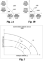
FIGs. 2A-2B illustrates a development of a baseline error space from a nominal error space in accordance with the present invention. -
FIG. 3 is an exemplary monitoring error space in accordance with the present invention. -
FIG. 4 is a block diagram of an engine friction monitoring system of the present invention. -
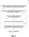
FIG. 5 is a flow diagram of one embodiment of an engine friction monitoring method of the present invention. -
FIGs. 6A-6E is an exemplary engine failure prediction technique based on a high confidence threshold for the monitoring error space in accordance with the present invention. -
FIGs. 7A-7E is an exemplary engine failure prediction technique based on an intermediate confidence threshold for the monitoring error space in accordance with the present invention. -
FIGs. 8A-8E is an exemplary engine failure prediction technique based on a low confidence threshold for the monitoring error space in accordance with the present invention. - For the purposes of promoting an understanding of the principles of the invention, reference will now be made to the embodiments illustrated in the drawings and specific language will be used to describe the same. It will nevertheless be understood that no limitation of the scope of the invention is thereby intended, any alterations and further modifications in the illustrated embodiments, and any further applications of the principles of the invention as illustrated therein as would normally occur to one skilled in the art to which the invention relates are contemplated herein.
- The present invention is applicable to any engine capable of converting various types of energy into mechanical force and motion, and further applicable to any engine control module for commanding a rotational force (i.e., torque) to be produced by an engine. The present invention describes an engine friction monitor system and method that uses commanded torque and measured torque, rate of change of torque, pattern recognition, and classification methods to provide a prognostic feature to identify potential failure of an engine that causes the engine from delivering the commanded torque due to an increase in friction on the engine components.
-
FIG. 1 shows an enginefriction learning module 10 of the present invention for baselining to learn behavior of a nominal, good engine system and provide confidence in the baseline models.Engine friction module 10 may provide data filtering and selection to extract the correct information to make decisions and classify the data to determine if the system is operating in a "good" condition or "bad" condition. As used herein, a "good" condition indicates a torque deviation of the engine from a commanded torque that is within one or more predetermined thresholds, i.e. that the engine friction amount is acceptable or within tolerances. A "bad" system indicates a torque deviation that is more than one or more thresholds indicative of an excessive friction condition for one or more components of the engine, i.e. that the engine friction amount is unacceptable or outside tolerances. - Engine
friction learning module 10 can include, for example, a computer module or circuit configured for processing a commanded torque CTOE and a measured torque MTOE from operational engine(s) and further process a commanded torque CTFE and a measured torque MTFE from failed engine(s) to generate a plottederror space 20P. This data is used to learn the plottederror space 20P, which is modified with subsequent data to learn abaseline error space 20B. - Plotted
error space 20P is defined by atorque error axis 21 and aslope error axis 22. For the present invention, a torque error is a differential between a commanded torque and a measured torque of a particular engine, such as, for this present invention, a differential between commanded torque CTOE and measured torque MTOE from an operational engine or a differential between commanded torque CTFE and measured torque MTFE from a failed engine. Slope error is determined in response to a differential between a rate of change of the commanded torque and a rate of change of the measured torque. Plottederror space 20P includes anominal threshold boundary 25P dividing plottederror space 20P into a "good"torque area 26P of plottedtorque errors 23P between commanded torque CTOE and measured torque MTOE from operational engines and a "bad"torque area 27P of plottedtorque errors 24P between commanded torque CTFE and measured torque MTFE from failed engines. - For an engine, there are a number of factors that could cause the torque errors including, but not limited to, component wear and drift, variability in a fuel system, and variation in alternator efficiency. Plotted
error space 20P trains the enginefriction learning module 10 to learn how the nominal system performs and produce a nominal threshold boundary based on initial data. - In
FIG. 2A , torque errors between commanded torque CTOE and measured torque MTOE are classified asgood torque errors 21G belownominal threshold boundary 25P ontorque error axis 21 from operational engines. Torque errors between commanded torque CTFE and measured torque MTFE from failed engines abovenominal threshold boundary 25P ontorque error axis 21 are classified asbad torque errors 21B. Slope or rate of change errors are initially classified asgood slope errors 22G belownominal threshold boundary 25P onslope error axis 22 from operational engines, andbad slope errors 22B from failed engines if abovenominal threshold boundary 25P onslope error axis 22. - Referring back to
FIG. 1 ,baseline error space 20B includes plottedgood torque errors 23P and plottedbad torque errors 24P that are baselined relative to an origin of plottederror space 20P to identify the nominal or initial behavior of the engine represented bynominal threshold boundary 25P. As more and more plottedgood torque errors 23P and plottedbad torque errors 24P are baselined, enginefriction learning module 10 computes a cumulative sum of the distances of the points from the origin of plottederror space 20P. This ensures points that are further away from thenominal threshold boundary 25P and are added to the "bad" area get weighted higher to provide appropriate weight to failures that cause significant impact on increased friction. As a result, the plottednominal threshold boundary 25P evolves intobaseline threshold boundary 25B over time as more data is collected. - Alternatives to baselining plotted
error space 20P based on a computation of a distance of each point from the origin are also contemplated. For example, other methods for supervised learning and classification may be applied to trainnominal threshold boundary 25P (e.g., a support vector machine) to learn abaseline threshold boundary 25B. - Baseline
torque error space 20B includesgood torque errors 23B belowbaseline threshold boundary 25B andbad torque errors 24B abovebaseline threshold boundary 25B.Baseline threshold boundary 25B divides baselinetorque error space 20B intogood torque area 26B andbad torque area 27B. InFIG. 2B , torque errors are initially classified asgood torque errors 21G' belowbaseline threshold boundary 25B ontorque error axis 21 from operational engines, andbad torque errors 21B' from failed engines abovebaseline threshold boundary 25B ontorque error axis 21. Slope or rate of change errors are initially classified asgood slope errors 22G' belowbaseline threshold boundary 25B onslope error axis 22 from operational engines, andbad slope errors 22B' from failed engines abovebaseline threshold boundary 25B onslope error axis 22. - Engine
friction learning module 10 outputs amonitoring error space 20M inFIG. 3 for monitoring an engine in real-time to thereby identify any failure modes of the engine that causes the engine from delivering commanded torque.Monitoring error space 20M is defined bytorque error axis 21 andslope error axis 22 and includes a monitoringbaseline threshold boundary monitoring error space 20M into a first, good torque area below the monitoringbaseline threshold boundary baseline threshold boundary baseline threshold boundary 25B (FIG. 1 ) serves as the initial high confidencemonitoring threshold boundary 25H for dividing the first and second torque areas and can be shifted based on a change in a confidence level of the torque data. - In an embodiment, engine
friction learning module 10 establishes a confidence level in engine conditions being utilized for learning including, but not limited to, how much torque data is being provided and a degree of variation of the torque data. As enginefriction learning module 10 trainsnominal threshold boundary 25P as previously described, enginefriction learning module 10 can establish a lowconfidence threshold boundary 25L reflective of a low confidence level in the conditions being conducive for predicting the impact of friction on the torque output, an intermediate threshold boundary 25I reflective of an intermediate confidence level in the engine conditions being conducive for prediction, and a highconfidence threshold boundary 25H reflective of a high confidence level in the engine conditions being conducive for predicting the impact of friction on the torque output. Enginefriction learning module 10 may thereby control the classification of data as "good" or "bad" based on the assigned confidence level for the predictive value of the data that is collected. - For example, as shown in
FIG. 3 , subsequent to a key on of an engine, enginefriction learning module 10 may stay at highconfidence threshold boundary 25H until such time the engine experiences operating conditions that provide less confidence being utilized for learning or predicting the impact due to engine friction (due to lack of information, too much variation, movement to a different load point, a key off event, etc.), the threshold boundary can transition 28I to intermediate confidence threshold boundary 25I. The confidence level can also transition 28C to a low confidence level 28L depending on the operating conditions. At lowconfidence threshold boundary 25L, the learning can be reset through a service tool if needed. The resetting of the confidence level allows the thresholds to be revisited and ensure more robustness in predictions and reduce the impact of uncertainty and new conditions on the prediction method. - With reference to
FIGS. 4 and5 , an engine friction monitor 50 of the present invention executes an engine friction monitoring method orprocedure 60 embodied by a flow diagram. In accordance with the method, engine friction monitor 50 processes torque of anengine 30 commanded and measured byECM 31 to identify potential failure modes ofengine 30 that causes the engine from being prevented in delivering the commanded torque. -
Engine 30 may be any type of engine including, but not limited to, an internal combustion engine. For example,engine 30 can be a gasoline engine, diesel engine, natural gas engine, dual fuel engine, or any other type of engine known in the art.Engine 30 can be employed in stationary applications, such as in powering a generator set, or in powering a vehicle, pump, or other equipment. - Engine control module (ECM) 31, monitor
enabler 40,torque signal processor 41, and/or engine friction monitor 50 can be implemented in hardware as one or more computer processing modules, circuits, and/or as instructions encoded on computer readable medium, and may be distributed across various hardware, computer processor or controller components or combined in a single controller or computer processor. - A
monitor enabler 40 receives enable condition signals ECS fromECM 31 to communicate an enable signal ES or a disable signal DS to engine friction monitor 50. Enable condition signals include, but are not limited to, a signal indicative of whether a circuit breaker is closed or open, whether a load request is present, an engine speed signal, an engine temperature condition, or any other condition that may be suitably required for monitoring of engine friction. - A
torque signal processor 41 is provided to receive commanded torque CTRT and measured torque MTRT in real-time fromECM 31 and applies a transient filtering of the torque to thereby communicate a conditioned commanded torque signal CTsc and conditioned measured torque signal MTsc to another module or circuit, such as atorque baseliner 51 of an enabled engine friction monitor 50. Engine friction monitor 50 also includes circuits or modules such as anerror calculator 52 and atorque classifier 53 in communication withtorque baseliner 51.Error calculator 52 determines a torque error TE and slope error SE from torque feedback target FT.Torque classifier 53 outputs classification points CP for the current operating conditions in response to the confidence level CL fromtorque baseliner 51 and the torque error TE and slope error SE fromerror calculator 52. Anengine failure predictor 54 includes a module or circuit that receives the operating classification points CP and outputs a failure prediction FP toECM 31.ECM 31 can then accumulate the indicators and take no action, provide an output such as a warning or alerts to have the engine serviced, and/or derate the engine completely or partially to prevent catastrophic damage or to limit the potential for damage depending on the failure prediction. - A flow diagram of an embodiment of a
procedure 60 for operation by engine friction monitor 50 is shown inFIG. 5 .Procedure 60 includes anoperation 62 in whichtorque baseliner 51 baselines conditioned commanded torque signal CTsc and conditioned measured torque signal MTsc in accordance with the training of engine friction monitor 50 as previously described herein. Atoperation 64 ofprocedure 60,torque baseliner 51 determines a confidence level CL and feedback target FT from conditioned commanded torque signal CTsc and conditioned measured torque signal MTsc. - An
operation 66 ofprocedure 60 includeserror calculator 52 calculating a torque error TE and slope error SE based on the feedback target FT.Torque classifier 53 plots torque error TE and slope error SE onmonitoring error space 20M (FIG. 3 ) relative to a selectedmonitoring threshold boundary operation 68, which are accumulated to provide a failure prediction as will be further described herein in connection withFIGS. 6-8 . -
Procedure 60 continues atoperation 70 which includesengine failure predictor 54 determining a failure prediction FP based on an accumulation of classification points as will be further described herein in connection withFIGS. 6-8 . Atoperation 72,procedure 60 returns tooperation 62 or terminates. - With reference to
FIGS. 6-8 , an accumulation of classification points within escalating indicator classification point buckets or caches 90-92 is illustrated for sequentially plotted classification points 80-83 relative to a highconfidence threshold boundary 25H, an intermediate confidence threshold boundary 25I and a lowconfidence threshold boundary 25L, respectively.Point bucket 90 represents classification points relating to a first level of monitoring ofengine 30, such that the number of "bad" classification points can be contained withinpoint bucket 90 and only call for a cautious monitoring.Point bucket 91 represents classification points for a second level of monitoring ofengine 30 due to the number of classification points classified as "bad" exceeding the capacity ofpoint bucket 90.Point bucket 92 represents classification points for a third level of monitoring ofengine 30, where the number of "bad" classification points exceed the capacity ofpoint buckets FIGS. 6-8 , another embodiment contemplates five escalating point buckets are used. However, it should be understood that any number of monitoring escalation levels and classification point buckets can be used. - Referring to
FIG. 6A , based on highconfidence threshold boundary 25H, plottedclassification point 80 is withingood torque area 26M while plotted classification points 81-83 are withinbad torque area 27M. Plottedclassification point 80 represents zero (0) classification points and no classification points are added to any of the point buckets 90-92 as shown inFIG. 6B . Plottedclassification point 81 represents non-zero classification points equal to or greater than a magnitude of avector 84 extending from highconfidence threshold boundary 25H to plottedclassification point 81 where the non-zero classification points are added to pointbucket 90 as shown inFIG. 6C . This addition can activate a caution or first level type of flag in the engine friction monitor 50 and/orECM 30. - Plotted
classification point 82 represents non-zero classification points equal to or greater than a magnitude of avector 85 extending from highconfidence threshold boundary 25H to plottedclassification point 82 where the non-zero classification points are added to pointbuckets FIG. 6D . This accumulation in the second buck can activate a concerned or second level type of flag. Plottedclassification point 83 represents non-zero classifications points equal to or greater than a magnitude of avector 86 extending from highconfidence threshold boundary 25H to plottedclassification point 83 where the non-zero classification points are added to pointbuckets FIG. 6E . This accumulation activates a failure prediction or third level flag or warning that is communicated toECM 31 upon filling ofpoint bucket 92. - Referring to
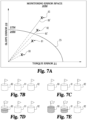
FIG. 7A , based on the intermediate confidence threshold boundary 25I, plottedclassification points good torque area 26M while plottedclassification points bad torque area 27M. Plottedclassification point 80 represents zero classification points being added to point buckets 90-92 as shown inFIG. 7B . Plottedclassification point 81 also represents zero classification points being added to point buckets 90-92 as shown inFIG. 7C . - Plotted
classification point 82 represents non-zero classifications points equal to a magnitude of a vector 85' extending from intermediate confidence threshold boundary 25I to plottedclassification point 82 where the non-zero classification points are added to pointbucket 90 as shown inFIG. 7D . This addition activates a cautious flag or first level of warning. Plottedclassification point 83 represents non-zero classification points equal to a magnitude of a vector 86' from intermediate confidence threshold boundary 25I to plottedclassification point 83 where the non-zero classification points are added to pointbuckets FIG. 7E . This accumulation intopoint bucket 91 activates a concerned flag or second level of warning. However, the shift in the confidence level boundary from high to intermediate results in less accumulation of classification points that indicate a potential failure as compared toFIGs. 6A-6E , thus reducing false alarms regarding a potential failure. - Referring to
FIG. 8A , based on lowconfidence threshold boundary 25L, plotted classification points 80-82 are all withingood torque area 26M while plottedclassification point 83 is withinbad torque area 27M. Plotted classification points 80, 81, and 82 represent zero classification points being added to point buckets 90-92 as shown inFIGs. 7B, 7C and 7D , respectively. - Plotted
classification point 83 represents non-zero classifications points equal to a magnitude of avector 85" extending from lowconfidence threshold boundary 25L to plottedclassification point 83 where the non-zero classification points are added to pointbucket 90 as shown inFIG. 7E . This addition activates a cautious flag or first level of warning, but again prevents raising of the alarms too rapidly based on torque data in which there is low confidence. The point classification method inFIGs. 6-8 , as shown, indicates the use of highconfidence threshold boundary 25H being employed for point classification during certain operating conditions provides for a high confidence in a failure prediction ofengine 30, while operating conditions that provide for lower confidence in point classification reduces the number of points classified as indicating a potential failure conditions, and therefore improve the quality in failure predictions and reduce the potential for false failure predictions. - The schematic flowchart diagram and method schematic diagrams described above are generally set forth as logical flow chart diagrams. As such, the depicted order and labeled steps are indicative of representative embodiments. Other steps, orderings and methods may be conceived that are equivalent in function, logic, or effect to one or more steps, or portions thereof, of the methods illustrated in the schematic diagrams.
- Additionally, the format and symbols employed are provided to explain the logical steps of the schematic diagrams and are understood not to limit the scope of the methods illustrated by the diagrams. Although various arrow types and line types may be employed in the schematic diagrams, they are understood not to limit the scope of the corresponding methods. Indeed, some arrows or other connectors may be used to indicate only the logical flow of a method. For instance, an arrow may indicate a waiting or monitoring period of unspecified duration between enumerated steps of a depicted method. Additionally, the order in which a particular method occurs may or may not strictly adhere to the order of the corresponding steps shown. It will also be noted that each block of the block diagrams and/or flowchart diagrams, and combinations of blocks in the block diagrams and/or flowchart diagrams, can be implemented by special purpose hardware-based systems that perform the specified functions or acts, or combinations of special purpose hardware and program code.
- Many of the functional units described in this specification have been labeled as modules, monitors, or circuits, in order to more particularly emphasize their implementation independence. For example, a module, monitor, or circuit may be implemented as a hardware circuit comprising custom VLSI circuits or gate arrays, off-the-shelf semiconductors such as logic chips, transistors, or other discrete components. A module, monitor, or circuit may also be implemented in programmable hardware devices such as field programmable gate arrays, programmable array logic, programmable logic devices or the like.
- Modules, monitors and circuits may also be implemented in machine-readable medium for execution by various types of processors. In some instances, the machine-readable medium for execution by various types of processors may be implemented in the aforementioned hardware circuit. An identified module of executable code may, for instance, comprise one or more physical or logical blocks of computer instructions, which may, for instance, be organized as an object, procedure, or function. Nevertheless, the executables of an identified module, monitor, or circuit need not be physically located together, but may comprise disparate instructions stored in different locations which, when joined logically together, comprise the module, monitor, or circuit and achieve the stated purpose for the module.
- For example, a module of computer readable program code may be a single instruction, or many instructions, and may even be distributed over several different code segments, among different programs, and across several memory devices. Similarly, operational data may be identified and illustrated herein within a module, monitor, or circuit, and may be embodied in any suitable form and organized within any suitable type of data structure. The operational data may be collected as a single data set, or may be distributed over different locations including over different storage devices, and may exist, at least partially, merely as electronic signals on a system or network. Where a module, monitor, or circuit or portions thereof are implemented in machine-readable medium (or computer-readable medium), the computer readable program code may be stored and/or propagated on one or more computer readable medium(s).
- The computer readable medium may be a tangible computer readable storage medium storing the computer readable program code. The computer readable storage medium may be, for example, but not limited to, an electronic, magnetic, optical, electromagnetic, infrared, holographic, micromechanical, or semiconductor system, apparatus, or device, or any suitable combination of the foregoing.
- More specific examples of the computer readable medium may include but are not limited to a portable computer diskette, a hard disk, a random access memory (RAM), a read-only memory (ROM), an erasable programmable read-only memory (EPROM or Flash memory), a portable compact disc read-only memory (CD-ROM), a digital versatile disc (DVD), an optical storage device, a magnetic storage device, a holographic storage medium, a micromechanical storage device, or any suitable combination of the foregoing. In the context of this document, a computer readable storage medium may be any tangible medium that can contain, and/or store computer readable program code for use by and/or in connection with an instruction execution system, apparatus, or device.
- The computer readable medium may also be a computer readable signal medium. A computer readable signal medium may include a propagated data signal with computer readable program code embodied therein, for example, in baseband or as part of a carrier wave. Such a propagated signal may take any of a variety of forms, including, but not limited to, electrical, electro-magnetic, magnetic, optical, or any suitable combination thereof. A computer readable signal medium may be any computer readable medium that is not a computer readable storage medium and that can communicate, propagate, or transport computer readable program code for use by or in connection with an instruction execution system, apparatus, or device. Computer readable program code embodied on a computer readable signal medium may be transmitted using any appropriate medium, including but not limited to wireless, wireline, optical fiber cable, Radio Frequency (RF), or the like, or any suitable combination of the foregoing.
- In one embodiment, the computer readable medium may comprise a combination of one or more computer readable storage mediums and one or more computer readable signal mediums. For example, computer readable program code may be both propagated as an electro-magnetic signal through a fiber optic cable for execution by a processor and stored on RAM storage device for execution by the processor.
- Computer readable program code for carrying out operations for aspects of the present invention may be written in any combination of one or more programming languages, including an object oriented programming language such as Java, Smalltalk, C++ or the like and conventional procedural programming languages, such as the "C" programming language or similar programming languages. The computer readable program code may execute entirely on the user's computer, partly on the user's computer, as a stand-alone computer-readable package, partly on the user's computer and partly on a remote computer or entirely on the remote computer or server. In the latter scenario, the remote computer may be connected to the user's computer through any type of network, including a local area network (LAN) or a wide area network (WAN), or the connection may be made to an external computer (for example, through the Internet using an Internet Service Provider).
- The program code may also be stored in a computer readable medium that can direct a computer, other programmable data processing apparatus, or other devices to function in a particular manner, such that the instructions stored in the computer readable medium produce an article of manufacture including instructions which implement the function/act specified in the schematic flowchart diagrams and/or schematic block diagrams block or blocks.
- Reference throughout this specification to "one embodiment," "an embodiment," or similar language means that a particular feature, structure, or characteristic described in connection with the embodiment is included in at least one embodiment of the present invention. Thus, appearances of the phrases "in one embodiment," "in an embodiment," and similar language throughout this specification may, but do not necessarily, all refer to the same embodiment.
- The described embodiments are to be considered in all respects only as illustrative and not restrictive. The scope of the invention is, therefore, indicated by the appended claims rather than by the foregoing description.
- While the invention has been illustrated and described in detail in the drawings and foregoing description, the same is to be considered as illustrative and not restrictive in character, it being understood that only certain exemplary embodiments have been shown and described. Those skilled in the art will appreciate that many modifications are possible in the example embodiments without materially departing from this invention. Accordingly, all such modifications are intended to be included within the scope of this invention as defined in the following claims.
- In reading the claims, it is intended that when words such as "a," "an," "at least one," or "at least one portion" are used there is no intention to limit the claim to only one item unless specifically stated to the contrary in the claim. When the language "at least a portion" and/or "a portion" is used the item can include a portion and/or the entire item unless specifically stated to the contrary.
Claims (15)
- A method for monitoring engine friction, comprising:determining a commanded torque (CTRT) and a measured torque (MTRT) of an engine (30);determining a torque error (21) in response to a differential between the commanded torque (CTRT) and the measured torque (MTRT), and determining (66) a slope error (22) in response to a differential between a rate of change of the commanded torque (CTRT) and a rate of change of the measured torque (MTRT);defining a baseline error space (20B) based on a learned torque error and a learned slope error and establishing a baseline threshold boundary (25B) within the baseline error space (20B) based on a monitoring confidence level (CL), the baseline threshold boundary (25B) dividing the baseline error space (20B) into a first torque area (26B) below the baseline threshold boundary (20B) and a second torque area (27B) above the baseline threshold boundary (25B); andclassifying torque data from the engine (30) in the first torque area (26B) and the second torque area (27B) based on the torque error (21) and the slope error (22), wherein the torque data classified in the second torque area (27B) is indicative of an engine friction condition.
- The method of claim 1, further comprising predicting a failure of the engine (30) based on the classified torque data.
- The method of claim 2, further comprising derating the engine (30) in response to the failure prediction.
- The method of claim 1, wherein classifying the torque data includes placing the torque data in the second torque area (27B) in one of a plurality of classification point buckets (90-92) based on a magnitude of the torque error in the second torque area (27B) relative to the baseline threshold boundary (20B); optionally wherein the plurality of classification point buckets (90-92) represent escalating indicators for a failure prediction (FP) of the engine (30).
- The method of claim 1, wherein defining the baseline error space (20B) includes learning a nominal error space (20P) having a nominal threshold boundary (25P) based on the learned torque error and the learned slope error; optionally wherein establishing the baseline threshold boundary (20B) includes modifying the nominal threshold boundary (25P) by weighting torque data over time that is classified in the second torque area (27B).
- A system for monitoring engine friction, comprising:an engine control module (31) for operably controlling an engine (30), wherein the engine control module (31) is configured to determine a commanded torque (CTRT) to the engine (30) and a measured torque (MTRT) from the engine (30);an engine friction monitor (50) that is configured to:determine a torque error (21) in response to a differential between the commanded torque (CTRT) and the measured torque (MTRT) and determine a slope error (22) in response to a differential between a rate of change of the commanded torque (CTRT) and a rate of change of the measured torque (MTRT);establish a baseline threshold boundary (25B) based on a learned torque error, a learned slope error, and a monitoring confidence level (CL), the baseline threshold boundary (25B) dividing a baseline error space (20B) into a first torque area (26B) below the baseline threshold boundary (25B) and a second torque area (27B) above the baseline threshold boundary (25B); andclassify torque data from the engine (30) into one of the first torque area (26B) and the second torque area (27B) based on the torque error (21) and the slope error (22), wherein the torque data classified in the second torque area (27B) is indicative of an engine friction condition.
- The system of claim 6, wherein the engine friction monitor (50) outputs a failure prediction (FP) to the engine control module (31) based on the classified torque data; optionally wherein the engine control module (31) is configured to derate the engine (30) in response to the failure prediction (FP).
- The system of claim 6, wherein the engine friction monitor (50) is configured to classify the torque data by placing the torque data in the second torque area (27B) in one of a plurality of classification point buckets (90-92) based on a magnitude of the torque error in the second torque area (27B) relative to the baseline threshold boundary (25B); optionally wherein the classification point buckets (90-92) represent escalating indicators for a failure prediction (FP) of the engine (30).
- The system of claim 6, wherein the engine friction monitor (50) is configured to modify the baseline threshold boundary (25B) by weighting torque data over time that is classified in the second torque area (27B).
- The system of claim 6, further comprising a monitor enabler (40) that is in communication with the engine friction monitor (50) that is configured to enable engine friction monitoring in response to one or more enablement conditions being present.
- The system of claim 6, wherein the engine friction monitor (50) comprises:a torque baseliner (51) configured to intermittently derive the monitoring confidence level (CL) from the commanded torque (CTRT) of the engine (30) and the measured torque (MTRT) of the engine (30), the monitoring confidence level (CL) being based on an operational status of the engine (30) as indicated by the commanded torque (CTRT) and the measured torque (MTRT), and wherein the torque baseliner (51) is further configured to intermittently derive a feedback target (FT) from the commanded torque (CTRT) and the measured torque (MTRT);an error calculator (52) configured to intermittently derive the torque error (21) and the slope error (22) in response to the feedback target (FT); anda torque classifier (53) configured to establish a monitoring threshold boundary (25H, 25L, 25I) within a monitoring error space in response to the monitoring confidence level (CL), and wherein the torque classifier (53) is further configured to classify points of torque data in one of the first and second torque areas (26B, 27B) based on the torque error (21) and the slope error (22).
- The system of claim 11, wherein the engine friction monitor (50) further comprises a failure predictor (54) configured to predict an impending engine failure from an accumulation of points classified in the second torque area (27B).
- The system of claim 11, wherein the torque baseliner (51) selects the monitoring confidence level (CL) between a first confidence level (25H) and a second confidence level (25L) that is lower than the first confidence level (25H) in response to engine operating conditions.
- The system of claim 11, wherein the engine control module (31) is configured to derate the engine (30) in response an output from the torque classifier (53).
- The system of claim 14, wherein the engine friction monitor (50) comprises:(i) a torque signal processor (41) that receives the commanded torque (CTRT) and the measured torque (MTRT) from the engine control module (31), and the torque signal processor (41) is configured to apply a transient filter to the commanded torque (CTRT) and the measured torque (MTRT) that is provided to the torque baseliner (51); or(ii) a monitor enabler (40) in communication with the engine control module (31) that is configured to enable engine friction monitoring in response to one or more enablement conditions being present.
Applications Claiming Priority (2)
| Application Number | Priority Date | Filing Date | Title |
|---|---|---|---|
| US201862651469P | 2018-04-02 | 2018-04-02 | |
| PCT/US2019/025385 WO2019195289A1 (en) | 2018-04-02 | 2019-04-02 | Engine friction monitor |
Publications (3)
| Publication Number | Publication Date |
|---|---|
| EP3759003A1 EP3759003A1 (en) | 2021-01-06 |
| EP3759003A4 EP3759003A4 (en) | 2021-12-01 |
| EP3759003B1 true EP3759003B1 (en) | 2023-08-02 |
Family
ID=68101487
Family Applications (1)
| Application Number | Title | Priority Date | Filing Date |
|---|---|---|---|
| EP19781246.4A Active EP3759003B1 (en) | 2018-04-02 | 2019-04-02 | Engine friction monitor |
Country Status (4)
| Country | Link |
|---|---|
| US (1) | US11993275B2 (en) |
| EP (1) | EP3759003B1 (en) |
| CN (1) | CN111936365B (en) |
| WO (1) | WO2019195289A1 (en) |
Families Citing this family (3)
| Publication number | Priority date | Publication date | Assignee | Title |
|---|---|---|---|---|
| CN111936365B (en) * | 2018-04-02 | 2023-09-26 | 卡明斯公司 | Engine friction monitor |
| CN115042803B (en) * | 2021-02-26 | 2025-11-25 | 通用汽车环球科技运作有限责任公司 | Driver-assisted autonomous driving systems that use the driver as a sensor to minimize disengagement from autonomous driving |
| CN115111078B (en) * | 2022-07-22 | 2024-03-19 | 浙江吉利控股集团有限公司 | Engine torque monitoring method, equipment and storage medium |
Family Cites Families (25)
| Publication number | Priority date | Publication date | Assignee | Title |
|---|---|---|---|---|
| US6188951B1 (en) | 1999-09-23 | 2001-02-13 | Daimlerchrysler Corporation | Engine friction characterization |
| US6714852B1 (en) | 2000-02-11 | 2004-03-30 | Ford Global Technologies, Llc | Observer for engine crankshaft torque |
| JP4089282B2 (en) | 2002-04-26 | 2008-05-28 | トヨタ自動車株式会社 | Calculation method of engine torque |
| US7090613B2 (en) * | 2004-05-15 | 2006-08-15 | General Motors Corporation | Method of providing electric motor torque reserve in a hybrid electric vehicle |
| JP2008014221A (en) * | 2006-07-06 | 2008-01-24 | Denso Corp | Control device for engine with auxiliary equipment |
| US7324888B1 (en) * | 2006-10-02 | 2008-01-29 | Ford Global Technologies, Llc | Computationally efficient data-driven algorithms for engine friction torque estimation |
| US8112194B2 (en) * | 2007-10-29 | 2012-02-07 | GM Global Technology Operations LLC | Method and apparatus for monitoring regenerative operation in a hybrid powertrain system |
| US8612107B2 (en) * | 2008-06-10 | 2013-12-17 | The Regents Of The University Of Michigan | Method, control apparatus and powertrain system controller for real-time, self-learning control based on individual operating style |
| US7844404B2 (en) | 2008-12-17 | 2010-11-30 | Honeywell International Inc. | Systems and methods for determining engine torque values |
| JP5663969B2 (en) * | 2009-06-30 | 2015-02-04 | 株式会社アドヴィックス | Longitudinal acceleration control device |
| US8437927B2 (en) | 2009-09-01 | 2013-05-07 | GM Global Technology Operations LLC | System and method for determining engine friction |
| US8489298B2 (en) * | 2009-09-09 | 2013-07-16 | GM Global Technology Operations LLC | Desired torque converter clutch slip feedback recovery algorithm for tip-in maneuvers |
| US8332109B2 (en) * | 2010-01-04 | 2012-12-11 | GM Global Technology Operations LLC | Closed-loop feedback control and reduction of the torque converter clutch slip for enhanced drivability for heavy tip-in maneuvers |
| US9566985B2 (en) * | 2011-02-08 | 2017-02-14 | GM Global Technology Operations LLC | Method and apparatus for monitoring a resolver in a torque machine |
| US8744707B2 (en) * | 2011-03-31 | 2014-06-03 | Caterpillar Inc. | CVT control using state space based gain scheduling |
| US20120324989A1 (en) | 2011-06-27 | 2012-12-27 | Caterpillar Inc. | System and method for diagnosis of engine component condition |
| CA2754137C (en) * | 2011-09-30 | 2012-11-20 | Westport Power Inc. | Apparatus and method for in situ fuel injector calibration in an internal combustion engine |
| US8924124B2 (en) * | 2012-01-17 | 2014-12-30 | Ford Global Technologies, Llc | Method and system for engine torque control |
| US9014918B2 (en) | 2012-10-12 | 2015-04-21 | Cummins Inc. | Health monitoring systems and techniques for vehicle systems |
| US9897582B2 (en) * | 2012-10-26 | 2018-02-20 | Pratt & Whitney Canada Corp. | Method and system for failure prediction using lubricating fluid analysis |
| CN105683548B (en) * | 2013-11-01 | 2019-05-31 | 卡明斯公司 | Engine control system and method for achieving torque values |
| US9751521B2 (en) * | 2014-04-17 | 2017-09-05 | Palo Alto Research Center Incorporated | Control system for hybrid vehicles with high degree of hybridization |
| US20160178464A1 (en) | 2014-12-19 | 2016-06-23 | Rolls-Royce Corporation | Torque sensor monitoring for gas turbine engine |
| US10732190B2 (en) * | 2018-01-31 | 2020-08-04 | Pratt & Whitney Canada Corp. | Method and system for predicting an engine condition |
| CN111936365B (en) * | 2018-04-02 | 2023-09-26 | 卡明斯公司 | Engine friction monitor |
-
2019
- 2019-04-02 CN CN201980023535.1A patent/CN111936365B/en active Active
- 2019-04-02 EP EP19781246.4A patent/EP3759003B1/en active Active
- 2019-04-02 WO PCT/US2019/025385 patent/WO2019195289A1/en not_active Ceased
-
2020
- 2020-09-21 US US17/026,699 patent/US11993275B2/en active Active
Also Published As
| Publication number | Publication date |
|---|---|
| CN111936365A (en) | 2020-11-13 |
| EP3759003A1 (en) | 2021-01-06 |
| CN111936365B (en) | 2023-09-26 |
| EP3759003A4 (en) | 2021-12-01 |
| US20210001871A1 (en) | 2021-01-07 |
| US11993275B2 (en) | 2024-05-28 |
| WO2019195289A1 (en) | 2019-10-10 |
Similar Documents
| Publication | Publication Date | Title |
|---|---|---|
| Shafi et al. | Vehicle remote health monitoring and prognostic maintenance system | |
| EP3759003B1 (en) | Engine friction monitor | |
| US8155820B2 (en) | Method, apparatus and computer program product for predicting and avoiding a fault | |
| KR101835344B1 (en) | Monitoring vehicle status system | |
| KR101565030B1 (en) | Decision system for error of car using the data analysis and method therefor | |
| JP7608419B2 (en) | Inspection system and method | |
| US20200402328A1 (en) | Closed loop parallel batch data logging in a vehicle | |
| CN119398749A (en) | A method and system for generating maintenance suggestions for a vehicle | |
| US20230360133A1 (en) | Method for configuring battery portpolio for providing financial service based on e-mobility battery valuation and apparatus for performing the method | |
| US12497041B2 (en) | Driver and lead vehicle prediction model | |
| US20230377035A1 (en) | Method of receiving real-time battery information and determining battery value for e-mobility of credit bureau (cb) and apparatus for performing the method | |
| WO2025254852A1 (en) | Systems and methods for identifying and predicting industrial machine maintenance events | |
| US20230127799A1 (en) | Sensor system for a vehicle | |
| US12441362B2 (en) | Vehicle control system | |
| EP4060576B1 (en) | A method for identifying vehicle performance | |
| Forrai et al. | Runtime Safety Assurance of Autonomous Vehicles | |
| US20230244792A1 (en) | Method for protecting against the theft of machine learning modules, and protection system | |
| US12576692B2 (en) | Thermal management control systems and methods | |
| US20230368298A1 (en) | Method for providing financial service base on e-mobility battery valuation and apparatus for performing the method | |
| Aravind et al. | Harnessing Artificial Intelligence for Enhanced Vehicle Control and Diagnostics | |
| US20250119295A1 (en) | Key storage system and method | |
| US20260042121A1 (en) | Apparatus and method for controlling a sorting line of second-hand batteries based on determined battery value | |
| US20240092391A1 (en) | Method for improving safety precautions for vehicles moving in an at least partially automated manner | |
| CN121833526A (en) | Scheduling test method based on vehicle-road cloud scheduling system and electronic equipment | |
| CN121469611A (en) | Methods for operating a driver assistance system, a driver assistance system, and computer programs |
Legal Events
| Date | Code | Title | Description |
|---|---|---|---|
| STAA | Information on the status of an ep patent application or granted ep patent |
Free format text: STATUS: THE INTERNATIONAL PUBLICATION HAS BEEN MADE |
|
| PUAI | Public reference made under article 153(3) epc to a published international application that has entered the european phase |
Free format text: ORIGINAL CODE: 0009012 |
|
| STAA | Information on the status of an ep patent application or granted ep patent |
Free format text: STATUS: REQUEST FOR EXAMINATION WAS MADE |
|
| 17P | Request for examination filed |
Effective date: 20200929 |
|
| AK | Designated contracting states |
Kind code of ref document: A1 Designated state(s): AL AT BE BG CH CY CZ DE DK EE ES FI FR GB GR HR HU IE IS IT LI LT LU LV MC MK MT NL NO PL PT RO RS SE SI SK SM TR |
|
| AX | Request for extension of the european patent |
Extension state: BA ME |
|
| DAV | Request for validation of the european patent (deleted) | ||
| DAX | Request for extension of the european patent (deleted) | ||
| REG | Reference to a national code |
Ref country code: DE Free format text: PREVIOUS MAIN CLASS: B60W0050020000 Ref country code: DE Ref legal event code: R079 Ref document number: 602019034122 Country of ref document: DE Free format text: PREVIOUS MAIN CLASS: B60W0050020000 Ipc: F02D0041220000 |
|
| A4 | Supplementary search report drawn up and despatched |
Effective date: 20211028 |
|
| RIC1 | Information provided on ipc code assigned before grant |
Ipc: F02D 41/22 20060101AFI20211022BHEP |
|
| GRAP | Despatch of communication of intention to grant a patent |
Free format text: ORIGINAL CODE: EPIDOSNIGR1 |
|
| STAA | Information on the status of an ep patent application or granted ep patent |
Free format text: STATUS: GRANT OF PATENT IS INTENDED |
|
| INTG | Intention to grant announced |
Effective date: 20230217 |
|
| P01 | Opt-out of the competence of the unified patent court (upc) registered |
Effective date: 20230510 |
|
| GRAS | Grant fee paid |
Free format text: ORIGINAL CODE: EPIDOSNIGR3 |
|
| GRAA | (expected) grant |
Free format text: ORIGINAL CODE: 0009210 |
|
| STAA | Information on the status of an ep patent application or granted ep patent |
Free format text: STATUS: THE PATENT HAS BEEN GRANTED |
|
| AK | Designated contracting states |
Kind code of ref document: B1 Designated state(s): AL AT BE BG CH CY CZ DE DK EE ES FI FR GB GR HR HU IE IS IT LI LT LU LV MC MK MT NL NO PL PT RO RS SE SI SK SM TR |
|
| RAP3 | Party data changed (applicant data changed or rights of an application transferred) |
Owner name: CUMMINS INC. |
|
| REG | Reference to a national code |
Ref country code: GB Ref legal event code: FG4D |
|
| REG | Reference to a national code |
Ref country code: CH Ref legal event code: EP |
|
| REG | Reference to a national code |
Ref country code: DE Ref legal event code: R096 Ref document number: 602019034122 Country of ref document: DE |
|
| REG | Reference to a national code |
Ref country code: IE Ref legal event code: FG4D |
|
| REG | Reference to a national code |
Ref country code: LT Ref legal event code: MG9D |
|
| REG | Reference to a national code |
Ref country code: NL Ref legal event code: MP Effective date: 20230802 |
|
| REG | Reference to a national code |
Ref country code: AT Ref legal event code: MK05 Ref document number: 1595013 Country of ref document: AT Kind code of ref document: T Effective date: 20230802 |
|
| PG25 | Lapsed in a contracting state [announced via postgrant information from national office to epo] |
Ref country code: GR Free format text: LAPSE BECAUSE OF FAILURE TO SUBMIT A TRANSLATION OF THE DESCRIPTION OR TO PAY THE FEE WITHIN THE PRESCRIBED TIME-LIMIT Effective date: 20231103 |
|
| PG25 | Lapsed in a contracting state [announced via postgrant information from national office to epo] |
Ref country code: IS Free format text: LAPSE BECAUSE OF FAILURE TO SUBMIT A TRANSLATION OF THE DESCRIPTION OR TO PAY THE FEE WITHIN THE PRESCRIBED TIME-LIMIT Effective date: 20231202 |
|
| PG25 | Lapsed in a contracting state [announced via postgrant information from national office to epo] |
Ref country code: SE Free format text: LAPSE BECAUSE OF FAILURE TO SUBMIT A TRANSLATION OF THE DESCRIPTION OR TO PAY THE FEE WITHIN THE PRESCRIBED TIME-LIMIT Effective date: 20230802 Ref country code: RS Free format text: LAPSE BECAUSE OF FAILURE TO SUBMIT A TRANSLATION OF THE DESCRIPTION OR TO PAY THE FEE WITHIN THE PRESCRIBED TIME-LIMIT Effective date: 20230802 Ref country code: PT Free format text: LAPSE BECAUSE OF FAILURE TO SUBMIT A TRANSLATION OF THE DESCRIPTION OR TO PAY THE FEE WITHIN THE PRESCRIBED TIME-LIMIT Effective date: 20231204 Ref country code: NO Free format text: LAPSE BECAUSE OF FAILURE TO SUBMIT A TRANSLATION OF THE DESCRIPTION OR TO PAY THE FEE WITHIN THE PRESCRIBED TIME-LIMIT Effective date: 20231102 Ref country code: NL Free format text: LAPSE BECAUSE OF FAILURE TO SUBMIT A TRANSLATION OF THE DESCRIPTION OR TO PAY THE FEE WITHIN THE PRESCRIBED TIME-LIMIT Effective date: 20230802 Ref country code: LV Free format text: LAPSE BECAUSE OF FAILURE TO SUBMIT A TRANSLATION OF THE DESCRIPTION OR TO PAY THE FEE WITHIN THE PRESCRIBED TIME-LIMIT Effective date: 20230802 Ref country code: LT Free format text: LAPSE BECAUSE OF FAILURE TO SUBMIT A TRANSLATION OF THE DESCRIPTION OR TO PAY THE FEE WITHIN THE PRESCRIBED TIME-LIMIT Effective date: 20230802 Ref country code: IS Free format text: LAPSE BECAUSE OF FAILURE TO SUBMIT A TRANSLATION OF THE DESCRIPTION OR TO PAY THE FEE WITHIN THE PRESCRIBED TIME-LIMIT Effective date: 20231202 Ref country code: HR Free format text: LAPSE BECAUSE OF FAILURE TO SUBMIT A TRANSLATION OF THE DESCRIPTION OR TO PAY THE FEE WITHIN THE PRESCRIBED TIME-LIMIT Effective date: 20230802 Ref country code: GR Free format text: LAPSE BECAUSE OF FAILURE TO SUBMIT A TRANSLATION OF THE DESCRIPTION OR TO PAY THE FEE WITHIN THE PRESCRIBED TIME-LIMIT Effective date: 20231103 Ref country code: FI Free format text: LAPSE BECAUSE OF FAILURE TO SUBMIT A TRANSLATION OF THE DESCRIPTION OR TO PAY THE FEE WITHIN THE PRESCRIBED TIME-LIMIT Effective date: 20230802 Ref country code: AT Free format text: LAPSE BECAUSE OF FAILURE TO SUBMIT A TRANSLATION OF THE DESCRIPTION OR TO PAY THE FEE WITHIN THE PRESCRIBED TIME-LIMIT Effective date: 20230802 |
|
| PG25 | Lapsed in a contracting state [announced via postgrant information from national office to epo] |
Ref country code: PL Free format text: LAPSE BECAUSE OF FAILURE TO SUBMIT A TRANSLATION OF THE DESCRIPTION OR TO PAY THE FEE WITHIN THE PRESCRIBED TIME-LIMIT Effective date: 20230802 |
|
| PG25 | Lapsed in a contracting state [announced via postgrant information from national office to epo] |
Ref country code: ES Free format text: LAPSE BECAUSE OF FAILURE TO SUBMIT A TRANSLATION OF THE DESCRIPTION OR TO PAY THE FEE WITHIN THE PRESCRIBED TIME-LIMIT Effective date: 20230802 |
|
| PG25 | Lapsed in a contracting state [announced via postgrant information from national office to epo] |
Ref country code: SM Free format text: LAPSE BECAUSE OF FAILURE TO SUBMIT A TRANSLATION OF THE DESCRIPTION OR TO PAY THE FEE WITHIN THE PRESCRIBED TIME-LIMIT Effective date: 20230802 Ref country code: RO Free format text: LAPSE BECAUSE OF FAILURE TO SUBMIT A TRANSLATION OF THE DESCRIPTION OR TO PAY THE FEE WITHIN THE PRESCRIBED TIME-LIMIT Effective date: 20230802 Ref country code: ES Free format text: LAPSE BECAUSE OF FAILURE TO SUBMIT A TRANSLATION OF THE DESCRIPTION OR TO PAY THE FEE WITHIN THE PRESCRIBED TIME-LIMIT Effective date: 20230802 Ref country code: EE Free format text: LAPSE BECAUSE OF FAILURE TO SUBMIT A TRANSLATION OF THE DESCRIPTION OR TO PAY THE FEE WITHIN THE PRESCRIBED TIME-LIMIT Effective date: 20230802 Ref country code: DK Free format text: LAPSE BECAUSE OF FAILURE TO SUBMIT A TRANSLATION OF THE DESCRIPTION OR TO PAY THE FEE WITHIN THE PRESCRIBED TIME-LIMIT Effective date: 20230802 Ref country code: CZ Free format text: LAPSE BECAUSE OF FAILURE TO SUBMIT A TRANSLATION OF THE DESCRIPTION OR TO PAY THE FEE WITHIN THE PRESCRIBED TIME-LIMIT Effective date: 20230802 Ref country code: SK Free format text: LAPSE BECAUSE OF FAILURE TO SUBMIT A TRANSLATION OF THE DESCRIPTION OR TO PAY THE FEE WITHIN THE PRESCRIBED TIME-LIMIT Effective date: 20230802 |
|
| REG | Reference to a national code |
Ref country code: DE Ref legal event code: R097 Ref document number: 602019034122 Country of ref document: DE |
|
| PG25 | Lapsed in a contracting state [announced via postgrant information from national office to epo] |
Ref country code: IT Free format text: LAPSE BECAUSE OF FAILURE TO SUBMIT A TRANSLATION OF THE DESCRIPTION OR TO PAY THE FEE WITHIN THE PRESCRIBED TIME-LIMIT Effective date: 20230802 |
|
| PLBE | No opposition filed within time limit |
Free format text: ORIGINAL CODE: 0009261 |
|
| STAA | Information on the status of an ep patent application or granted ep patent |
Free format text: STATUS: NO OPPOSITION FILED WITHIN TIME LIMIT |
|
| 26N | No opposition filed |
Effective date: 20240503 |
|
| PG25 | Lapsed in a contracting state [announced via postgrant information from national office to epo] |
Ref country code: SI Free format text: LAPSE BECAUSE OF FAILURE TO SUBMIT A TRANSLATION OF THE DESCRIPTION OR TO PAY THE FEE WITHIN THE PRESCRIBED TIME-LIMIT Effective date: 20230802 |
|
| PG25 | Lapsed in a contracting state [announced via postgrant information from national office to epo] |
Ref country code: BG Free format text: LAPSE BECAUSE OF FAILURE TO SUBMIT A TRANSLATION OF THE DESCRIPTION OR TO PAY THE FEE WITHIN THE PRESCRIBED TIME-LIMIT Effective date: 20230802 |
|
| PG25 | Lapsed in a contracting state [announced via postgrant information from national office to epo] |
Ref country code: MC Free format text: LAPSE BECAUSE OF FAILURE TO SUBMIT A TRANSLATION OF THE DESCRIPTION OR TO PAY THE FEE WITHIN THE PRESCRIBED TIME-LIMIT Effective date: 20230802 |
|
| PG25 | Lapsed in a contracting state [announced via postgrant information from national office to epo] |
Ref country code: MC Free format text: LAPSE BECAUSE OF FAILURE TO SUBMIT A TRANSLATION OF THE DESCRIPTION OR TO PAY THE FEE WITHIN THE PRESCRIBED TIME-LIMIT Effective date: 20230802 Ref country code: BG Free format text: LAPSE BECAUSE OF FAILURE TO SUBMIT A TRANSLATION OF THE DESCRIPTION OR TO PAY THE FEE WITHIN THE PRESCRIBED TIME-LIMIT Effective date: 20230802 |
|
| REG | Reference to a national code |
Ref country code: CH Ref legal event code: PL |
|
| PG25 | Lapsed in a contracting state [announced via postgrant information from national office to epo] |
Ref country code: LU Free format text: LAPSE BECAUSE OF NON-PAYMENT OF DUE FEES Effective date: 20240402 |
|
| REG | Reference to a national code |
Ref country code: BE Ref legal event code: MM Effective date: 20240430 |
|
| PG25 | Lapsed in a contracting state [announced via postgrant information from national office to epo] |
Ref country code: LU Free format text: LAPSE BECAUSE OF NON-PAYMENT OF DUE FEES Effective date: 20240402 |
|
| PG25 | Lapsed in a contracting state [announced via postgrant information from national office to epo] |
Ref country code: BE Free format text: LAPSE BECAUSE OF NON-PAYMENT OF DUE FEES Effective date: 20240430 |
|
| PG25 | Lapsed in a contracting state [announced via postgrant information from national office to epo] |
Ref country code: FR Free format text: LAPSE BECAUSE OF NON-PAYMENT OF DUE FEES Effective date: 20240430 |
|
| PG25 | Lapsed in a contracting state [announced via postgrant information from national office to epo] |
Ref country code: FR Free format text: LAPSE BECAUSE OF NON-PAYMENT OF DUE FEES Effective date: 20240430 Ref country code: BE Free format text: LAPSE BECAUSE OF NON-PAYMENT OF DUE FEES Effective date: 20240430 Ref country code: CH Free format text: LAPSE BECAUSE OF NON-PAYMENT OF DUE FEES Effective date: 20240430 |
|
| PG25 | Lapsed in a contracting state [announced via postgrant information from national office to epo] |
Ref country code: IE Free format text: LAPSE BECAUSE OF NON-PAYMENT OF DUE FEES Effective date: 20240402 |
|
| PGFP | Annual fee paid to national office [announced via postgrant information from national office to epo] |
Ref country code: DE Payment date: 20250429 Year of fee payment: 7 |
|
| PGFP | Annual fee paid to national office [announced via postgrant information from national office to epo] |
Ref country code: GB Payment date: 20250428 Year of fee payment: 7 |
|
| PG25 | Lapsed in a contracting state [announced via postgrant information from national office to epo] |
Ref country code: CY Free format text: LAPSE BECAUSE OF FAILURE TO SUBMIT A TRANSLATION OF THE DESCRIPTION OR TO PAY THE FEE WITHIN THE PRESCRIBED TIME-LIMIT; INVALID AB INITIO Effective date: 20190402 |
|
| PG25 | Lapsed in a contracting state [announced via postgrant information from national office to epo] |
Ref country code: HU Free format text: LAPSE BECAUSE OF FAILURE TO SUBMIT A TRANSLATION OF THE DESCRIPTION OR TO PAY THE FEE WITHIN THE PRESCRIBED TIME-LIMIT; INVALID AB INITIO Effective date: 20190402 |
|
| PG25 | Lapsed in a contracting state [announced via postgrant information from national office to epo] |
Ref country code: TR Free format text: LAPSE BECAUSE OF FAILURE TO SUBMIT A TRANSLATION OF THE DESCRIPTION OR TO PAY THE FEE WITHIN THE PRESCRIBED TIME-LIMIT Effective date: 20230802 |