EP3758617B1 - Devices for suture placement - Google Patents
Devices for suture placement Download PDFInfo
- Publication number
- EP3758617B1 EP3758617B1 EP19760629.6A EP19760629A EP3758617B1 EP 3758617 B1 EP3758617 B1 EP 3758617B1 EP 19760629 A EP19760629 A EP 19760629A EP 3758617 B1 EP3758617 B1 EP 3758617B1
- Authority
- EP
- European Patent Office
- Prior art keywords
- needle
- curved
- distal
- passage
- suturing device
- Prior art date
- Legal status (The legal status is an assumption and is not a legal conclusion. Google has not performed a legal analysis and makes no representation as to the accuracy of the status listed.)
- Active
Links
Images



Classifications
-
- A—HUMAN NECESSITIES
- A61—MEDICAL OR VETERINARY SCIENCE; HYGIENE
- A61B—DIAGNOSIS; SURGERY; IDENTIFICATION
- A61B17/00—Surgical instruments, devices or methods
- A61B17/04—Surgical instruments, devices or methods for suturing wounds; Holders or packages for needles or suture materials
- A61B17/06—Needles ; Sutures; Needle-suture combinations; Holders or packages for needles or suture materials
- A61B17/06066—Needles, e.g. needle tip configurations
-
- A—HUMAN NECESSITIES
- A61—MEDICAL OR VETERINARY SCIENCE; HYGIENE
- A61B—DIAGNOSIS; SURGERY; IDENTIFICATION
- A61B17/00—Surgical instruments, devices or methods
- A61B17/04—Surgical instruments, devices or methods for suturing wounds; Holders or packages for needles or suture materials
- A61B17/0482—Needle or suture guides
-
- A—HUMAN NECESSITIES
- A61—MEDICAL OR VETERINARY SCIENCE; HYGIENE
- A61B—DIAGNOSIS; SURGERY; IDENTIFICATION
- A61B17/00—Surgical instruments, devices or methods
- A61B17/04—Surgical instruments, devices or methods for suturing wounds; Holders or packages for needles or suture materials
- A61B17/06—Needles ; Sutures; Needle-suture combinations; Holders or packages for needles or suture materials
- A61B17/06061—Holders for needles or sutures, e.g. racks, stands
-
- A—HUMAN NECESSITIES
- A61—MEDICAL OR VETERINARY SCIENCE; HYGIENE
- A61B—DIAGNOSIS; SURGERY; IDENTIFICATION
- A61B17/00—Surgical instruments, devices or methods
- A61B2017/00681—Aspects not otherwise provided for
- A61B2017/00738—Aspects not otherwise provided for part of the tool being offset with respect to a main axis, e.g. for better view for the surgeon
-
- A—HUMAN NECESSITIES
- A61—MEDICAL OR VETERINARY SCIENCE; HYGIENE
- A61B—DIAGNOSIS; SURGERY; IDENTIFICATION
- A61B17/00—Surgical instruments, devices or methods
- A61B17/04—Surgical instruments, devices or methods for suturing wounds; Holders or packages for needles or suture materials
- A61B17/06—Needles ; Sutures; Needle-suture combinations; Holders or packages for needles or suture materials
- A61B2017/06052—Needle-suture combinations in which a suture is extending inside a hollow tubular needle, e.g. over the entire length of the needle
-
- A—HUMAN NECESSITIES
- A61—MEDICAL OR VETERINARY SCIENCE; HYGIENE
- A61B—DIAGNOSIS; SURGERY; IDENTIFICATION
- A61B17/00—Surgical instruments, devices or methods
- A61B17/04—Surgical instruments, devices or methods for suturing wounds; Holders or packages for needles or suture materials
- A61B17/06—Needles ; Sutures; Needle-suture combinations; Holders or packages for needles or suture materials
- A61B17/06066—Needles, e.g. needle tip configurations
- A61B2017/0608—J-shaped
Definitions
- the present disclosure relates generally to surgery and the placement of sutures, and more particularly, to a device for the suture repair of tissue according to the preamble of claim 1.
- Surgical closure techniques using a needle to pass a suture is one approach to tissue repair. Maintaining the needle within the device that is used to deploy the needle through the tissue can present challenges.
- a suturing device is known from WO 2017/136022 A1 .
- a needle is positioned within a curved needle passage of a curved needle holder such as to contact an inner surface of the needle passage at three locations spaced from each other along the needle passage.
- This suturing device includes a needle, a suture, an elongate body, an actuator and a curved needle holder.
- the needle has first end, which is pointed, a second end, a curved distal section and a straighter proximal section, which is straight or has a radius of curvature greater than the curved distal section.
- the suture connects with the needle.
- the elongate body includes a proximal end portion and a distal end portion.
- the actuator includes a mechanism operable to move the needle with respect to the elongate body.
- the curved needle holder extends away from the distal end portion or is provided as part of the distal end portion of the elongate body.
- the curved needle holder includes an inner surface defining a curved needle passage for holding the needle and a distal opening through which the needle exits the curved needle holder when moving from a retracted position toward a released condition. The needle frictionally engages the inner surface when the needle is in the retracted position.
- FIG. 1 depicts an example of a suturing device 10 that is useful to suture tears in tissue and that can be used in many different types of surgical procedures.
- the suturing device 10 generally includes an actuator button 12, an elongate body 14, and a needle holder 16.
- the suturing device 10 is particularly useful during a minimally invasive surgical procedure that is performed through a tubular retractor or other small surgical portal to accurately locate a needle 20 and a suture 22, which are shown in FIG. 2 , to facilitate passing the needle 20 through target tissue to be sutured.
- the needle 20 in the illustrated embodiment has a first end 30, which is pointed, and a second end 32, which is opposite to the first end 30.
- the needle 20 includes a curved distal section 34 and a straighter proximal section 36.
- the length of the curved distal section 34 is more than one half of the overall length of the needle 20.
- the curved distal section 34 extends from the first end 30 toward the second end 32 for about 60% of the overall length of the needle
- the straighter proximal section 36 extends from the second end 32 toward the first end 30 for about 40% of the overall length of the needle 20.
- the straighter proximal section 36 can extend from the second end 32 toward the first end 30 for less than 40% of the overall length of the needle 20, so long as the needle 20 frictionally engages with the needle holder 16 as described in more detail below.
- straighter proximal section 36 is shown as straight in that a central axis of the straighter proximal section 36 follows a line.
- the straighter proximal section 36 need not be exactly straight, but instead could have a radius of curvature greater, or vastly greater, than the curved distal section 34.
- the actuator button 12 is a component of an actuator that is described in more detail in U.S. App. Serial No. 15/654878 and for the sake of brevity will not be described in detail herein.
- actuation of the actuator button 12 results in the needle 20 moving in an advance direction 38 with respect to the needle holder 16.
- the needle 20 moves from a retracted position, which is shown in FIG. 3 , to a released condition in which the needle 20 is released from the needle holder 16.
- the surgeon can grasp the needle 20, for example with forceps, and pull the needle 20 and the suture 22.
- the suture 22 connects with the needle 20 and extends from the second end 32 of the needle 20.
- the suture 22 can be acquired from known suture manufacturers.
- the suture 22 can be swaged to the second end 32 of the needle 20. Swaging the suture 22 to the second end 32 of the needle 20 can result in straightening of a previously curved needle to provide the straighter proximal section 36.
- the suture 22 can also connect with the needle 20 in other conventional manners.
- the actuator which includes the actuator button 12, is operable between a first operating position and a second operating position. Movement of the actuator from the first operating position toward the second operating position moves the needle 20 in the advance direction 38 with respect to the needle holder 16 thus moving the needle 20 toward the released condition in which the needle 20 is released from the needle holder 16.
- the actuator includes a flexible section, which in the illustrated embodiment is made up of a wire 40, which can be made from nitinol.
- the wire 40 includes a distal end 42 and is configured to bend within the needle holder 16 when the actuator is moved from the first operating position toward the second operating position.
- the elongate body 14 connects with a handle 50.
- the elongate body 14 in the illustrated embodiment is in the form of a cannula and defines a track 44, which can be a lumen, that receives the wire 40.
- the elongate body 14 has a bayonet configuration in the illustrated embodiment; however, the elongate body 14 could take alternative configurations, such as straight along a longitudinal axis.
- the elongate body 14 includes the proximal end portion 70 and a distal end portion 72 connected by an intermediate portion 74. The proximal end portion 70 connects with the handle 50.
- the needle holder 16 is received in and connected with the elongate body 14 and extends away from the distal end portion 72.
- the needle holder 16 can be provided as part of the distal end portion 72 of the elongate body 14.
- the elongate body 14 is made from a rigid metal material; however, if desired at least a portion of the elongate body 14 may be made from a malleable or flexible material.
- an outer diameter of the elongate body 14 is constant between the proximal end portion 70 and the distal end portion 72. The outer diameter can be less than 3.5 mm, which provides a very slim device to enhance the line of sight for a surgeon during the surgical procedure.
- the intermediate portion 74 is positioned between the proximal end portion 70 and the distal end portion 72.
- the proximal end portion 70 extends along a proximal end portion longitudinal axis 76.
- the distal end portion 72 extends along a distal end portion longitudinal axis 78, which is offset from the proximal end portion longitudinal axis 76 in a forward direction.
- the distal end portion longitudinal axis 78 is offset from the proximal end portion longitudinal axis 76 about 25 mm.
- the proximal end portion 70 transitions to the intermediate portion 74 through a proximal bend 82 and the intermediate portion 74 transitions to the distal end portion 72 through a distal bend 84.
- the proximal bend 82 and the distal bend 84 are both angled internally 135 degrees.
- the needle holder 16 extends away from the distal end portion 72 or is provided as part of the distal end portion 72 of the elongate body 14.
- the needle holder 16 is a hollow tubular member.
- a portion of the needle holder 16 that is aligned with the distal end portion longitudinal axis 78 is received inside the elongate body 14; however, the needle holder 16 could be formed as part of the elongate body, e.g., both the elongate body 14 and the needle holder 16 could be made from one tubular stock material.
- the needle holder 16 depicted in the illustrated embodiment is a curved needle holder that generally follows a constant needle passage radius 90 ( FIG.
- the suturing device 10 can have J-hook configuration at a distal end thereof.
- the needle holder 16 is not intended to be removable from the elongate body 14; however, in an alternative arrangement the needle holder 16 can selectively connect with the elongate body 14 via a mechanical connection such as a friction fit or a bayonet connection.
- the needle holder 16 defines a needle passage 88 that follows the needle passage radius 90 and is in communication with the track 44.
- the needle passage 88 terminates at a distal opening 92 adjacent a distal-most tip 94 of the needle holder 16.
- the needle passage 88 follows an arc length less than about 140 degrees between a location where the needle holder 16 begins to curve away from the distal end portion longitudinal axis 78 and the distal-most tip 94.
- the distal opening 92 is offset from the distal end portion longitudinal axis 78 in a forward direction. In the embodiment depicted in FIG.
- the suture 22 extends along the needle passage 88 from the second end 32 of the needle 20 toward the distal opening 92 between the needle 20 and an inner surface 96 of the needle holder 16 when the needle 20 is received in the needle passage 88 and in the retracted position.
- the distal-most tip 94 is offset from the distal end portion longitudinal axis 78 in a direction perpendicular from the distal end portion longitudinal axis 78 a distance of less than 7 mm.
- Common tubular retractors used during minimally invasive spinal surgery procedures have diameters measuring between 14 mm to 22 mm.
- the surgeon can locate the elongate body 14 along the central axis of the tubular retractor and rotate the suturing device around the central axis without contacting the side of the tubular retractor.
- the needle holder 16 includes a distal notch 98 at the distal opening 92 adjacent the distal-most tip 94.
- the distal notch 98 extends in a proximal direction toward the elongate body 14.
- the second end 32 of the needle 20 need not travel past the distal-most tip 94 of the needle holder 16 before being released from the needle holder 16.
- Such a configuration of the distal opening 92 also facilitates loading of the needle 20 and the suture 22 into the needle passage 88, which occurs by inserting the second end 32 of the needle 20 into the distal opening 92 and moving the needle 20 with respect to the needle holder 16 in a direction opposite to the advance direction 38.
- the configuration of the distal opening 92 also reduces the likelihood that the first end 30 of the needle 20 may pass through the suture 22 when being passed through the target tissue.
- the distal notch 98 is depicted on the side of the needle holder 16, however, the distal notch 98 can be located elsewhere. By providing the distal notch 98, the distal opening 92 is non-circular.
- the distal-most tip 94 can also be rounded, which allows for the surgeon to grab or "hook" the target tissue, which is to be sutured, on an internal side thereof and indent the target tissue with the distal-most tip 94 while not catching the target tissue with the first (pointed) end 30 of the needle 20.
- the needle holder 16 also includes a proximal hole 102 defined by a peripheral edge 104 and spaced from the distal opening 92.
- the proximal hole 102 is elongated along the distal end portion longitudinal axis 78.
- the proximal hole 102 extends through an inner side of the needle holder 16 in that the proximal hole 102 is located through a side of the needle holder 16 nearest to the center of the needle passage radius 90.
- a lower end 106 of the proximal hole 102 is located near where the second end 32 of the needle 20 resides when the needle 20 in the retracted position.
- An upper end 108 of the proximal hole 102 is located above (i.e., toward the handle 50) from the distal end 42 of the wire 40.
- a needle retainer can be provided to retain the needle 20 within the needle passage 88 to inhibit unintended movement of the needle 20 with respect to the needle holder 16.
- a needle retainer is a flexible sheath 114 that is shown as transparent in FIG. 2 .
- the flexible sheath 114 surrounds the needle holder 16 and terminates at a lower end 116, which is located adjacent the lower end 106 of the proximal hole 102.
- the flexible sheath 114 extends into the proximal hole 102 to retain the second end 32 of the needle 20 against the inner surface 96 of the needle holder 16 when the needle 20 is received in the needle passage 88 in the retracted position.
- An entirety of the flexible sheath 114 can be made from a resilient material, or the portion of the flexible sheath 114 that extends into the needle passage 88 through the proximal hole 102 may be made from the resilient material.
- the flexible sheath 114 can conform to the peripheral edge 104 of the proximal hole 102 and urge the distal end 42 of the wire 40 and the second end 32 of the needle 20 toward an outer side of the inner surface 96 of the needle holder 16, i.e., the side of the inner surface 96 spaced farthest from the center of the needle passage radius 90.
- the flexible sheath 114 effectively reduces the cross section, or inner diameter, of the track 44 and the needle passage 88 and acts to guide the distal end 42 of the wire 40 toward the second end 32 of the needle 20 when the distal end 42 is moved toward the needle 20.
- the wire 40 in the illustrated embodiment presses against the second end 32 of the needle 20 overcoming the retaining force of the flexible sheath 114 and moves the needle 20 in the advance direction 38.
- the needle 20 When the needle 20 is in the retracted position, the needle 20 is in contact with the inner surface 96 of the needle holder 16 to inhibit unintended movement of the needle 20 with respect to the needle holder 16.
- the needle 20 contacts the inner surface 96 in at least three different locations along the length, or arc length, of the needle 20, e.g., a first location 124, a second location 126 and a third location 128, which are depicted in FIG. 3 .
- the first location 124 is located adjacent to the second end 32 of the needle 20.
- the second location 126 is located offset of the second end 32 and toward the first end 30 of the needle 20.
- the third location 128 is located offset of the first end 30 and toward the second end 32 of the needle 20.
- the first location 124 and the third location 128 are located on an outer surface of the needle 20, i.e. the surface of the needle 20 spaced farthest from the center of the needle passage radius 90 ( FIG. 5 ).
- the second location 126 is along an inner surface of the needle 20 with respect to the center of the needle passage radius 90.
- the first location 124 and the second location 126 are located along the straighter proximal section 36 ( FIG. 4 ) of the needle 20, and the third location 128 is located along the curved distal section 34 of the needle 20.
- the curved distal section 34 which can have a curved needle radius 130 ( FIG. 4 ) similar to the needle passage radius 90, and with the straighter proximal section 36 results in the needle 20 being wedged into the needle holder 16.
- the three contact locations 124, 126, 128 keep the needle 20 retained and stable in the retracted position until the needle 20 is pushed by the wire 40.
- the curved distal section 34 can have a curved needle radius 130 of 3.4 mm and the needle passage radius 90 can be 4.0 mm, which results in the curved needle radius 130 being about 85% of the needle passage radius 90.
- the straighter proximal section 36 extends from the second end 32 long enough, which may or may not be at least about 40% of the overall length of the needle 20, so that the needle 20 frictionally engages the inner surface 96 of the needle holder 16.
- the needle 20 can have a maximum outer diameter that is at least 40% of the inner diameter of the needle passage 88, which can facilitate retaining the needle 20 within the needle passage 88.
- the needle 20 can have an outer diameter that is not greater than 90% of the inner diameter of the needle passage 88, which can allow the needle passage 88 to accommodate both the needle 20 and the suture 22.
Landscapes
- Health & Medical Sciences (AREA)
- Life Sciences & Earth Sciences (AREA)
- Surgery (AREA)
- Heart & Thoracic Surgery (AREA)
- Engineering & Computer Science (AREA)
- Biomedical Technology (AREA)
- Nuclear Medicine, Radiotherapy & Molecular Imaging (AREA)
- Medical Informatics (AREA)
- Molecular Biology (AREA)
- Animal Behavior & Ethology (AREA)
- General Health & Medical Sciences (AREA)
- Public Health (AREA)
- Veterinary Medicine (AREA)
- Surgical Instruments (AREA)
Description
- The present disclosure relates generally to surgery and the placement of sutures, and more particularly, to a device for the suture repair of tissue according to the preamble of claim 1.
- Surgical closure techniques using a needle to pass a suture is one approach to tissue repair. Maintaining the needle within the device that is used to deploy the needle through the tissue can present challenges.
- A suturing device according to the preamble of claim 1 is known from
WO 2017/136022 A1 . In this known suturing device, a needle is positioned within a curved needle passage of a curved needle holder such as to contact an inner surface of the needle passage at three locations spaced from each other along the needle passage. - It is the object of the present invention to provide a suturing device in which a needle is kept retained and stable within a curved needle passage of a curved needle holder for the activation by a mechanism operable to move the needle out of the needle passage.
- According to the present invention, this object is solved by the suturing device according to claim 1. This suturing device includes a needle, a suture, an elongate body, an actuator and a curved needle holder. The needle has first end, which is pointed, a second end, a curved distal section and a straighter proximal section, which is straight or has a radius of curvature greater than the curved distal section. The suture connects with the needle. The elongate body includes a proximal end portion and a distal end portion. The actuator includes a mechanism operable to move the needle with respect to the elongate body. The curved needle holder extends away from the distal end portion or is provided as part of the distal end portion of the elongate body. The curved needle holder includes an inner surface defining a curved needle passage for holding the needle and a distal opening through which the needle exits the curved needle holder when moving from a retracted position toward a released condition. The needle frictionally engages the inner surface when the needle is in the retracted position.
-
-
FIG. 1 is a perspective view a suturing device. -
FIG. 2 is a side view of a distal portion of the suturing device ofFIG. 1 . -
FIG. 3 is a cross-sectional view of the distal portion of the suturing device ofFIG. 1 . -
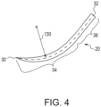
FIG. 4 is a side view of a needle of the suturing device ofFIG. 1 . -
FIG. 5 is another cross-sectional view of the distal portion of the suturing device ofFIG. 1 with the needle and suture removed. -
FIG. 1 depicts an example of asuturing device 10 that is useful to suture tears in tissue and that can be used in many different types of surgical procedures. Thesuturing device 10 generally includes anactuator button 12, anelongate body 14, and aneedle holder 16. Thesuturing device 10 is particularly useful during a minimally invasive surgical procedure that is performed through a tubular retractor or other small surgical portal to accurately locate aneedle 20 and asuture 22, which are shown inFIG. 2 , to facilitate passing theneedle 20 through target tissue to be sutured. - With reference to
FIG. 3 , theneedle 20 in the illustrated embodiment has afirst end 30, which is pointed, and asecond end 32, which is opposite to thefirst end 30. With reference toFIG. 4 , theneedle 20 includes a curveddistal section 34 and a straighterproximal section 36. The length of thecurved distal section 34 is more than one half of the overall length of theneedle 20. In the illustrated embodiment, the curveddistal section 34 extends from thefirst end 30 toward thesecond end 32 for about 60% of the overall length of the needle, and the straighterproximal section 36 extends from thesecond end 32 toward thefirst end 30 for about 40% of the overall length of theneedle 20. The straighterproximal section 36 can extend from thesecond end 32 toward thefirst end 30 for less than 40% of the overall length of theneedle 20, so long as theneedle 20 frictionally engages with theneedle holder 16 as described in more detail below. With continued reference toFIG. 4 , straighterproximal section 36 is shown as straight in that a central axis of the straighterproximal section 36 follows a line. The straighterproximal section 36 need not be exactly straight, but instead could have a radius of curvature greater, or vastly greater, than the curveddistal section 34. - With reference back to
FIG. 1 , theactuator button 12 is a component of an actuator that is described in more detail inU.S. App. Serial No. 15/654878 and for the sake of brevity will not be described in detail herein. With reference toFIG. 2 , actuation of theactuator button 12 results in theneedle 20 moving in anadvance direction 38 with respect to theneedle holder 16. Theneedle 20 moves from a retracted position, which is shown inFIG. 3 , to a released condition in which theneedle 20 is released from theneedle holder 16. When in the released condition, the surgeon can grasp theneedle 20, for example with forceps, and pull theneedle 20 and thesuture 22. - The
suture 22 connects with theneedle 20 and extends from thesecond end 32 of theneedle 20. Thesuture 22 can be acquired from known suture manufacturers. Thesuture 22 can be swaged to thesecond end 32 of theneedle 20. Swaging thesuture 22 to thesecond end 32 of theneedle 20 can result in straightening of a previously curved needle to provide the straighterproximal section 36. Thesuture 22 can also connect with theneedle 20 in other conventional manners. - The actuator, which includes the
actuator button 12, is operable between a first operating position and a second operating position. Movement of the actuator from the first operating position toward the second operating position moves theneedle 20 in theadvance direction 38 with respect to theneedle holder 16 thus moving theneedle 20 toward the released condition in which theneedle 20 is released from theneedle holder 16. In the illustrated embodiment and with reference toFIG. 3 , the actuator includes a flexible section, which in the illustrated embodiment is made up of awire 40, which can be made from nitinol. Thewire 40 includes adistal end 42 and is configured to bend within theneedle holder 16 when the actuator is moved from the first operating position toward the second operating position. - With reference back to
FIG. 1 , theelongate body 14 connects with ahandle 50. Theelongate body 14 in the illustrated embodiment is in the form of a cannula and defines atrack 44, which can be a lumen, that receives thewire 40. Theelongate body 14 has a bayonet configuration in the illustrated embodiment; however, theelongate body 14 could take alternative configurations, such as straight along a longitudinal axis. Theelongate body 14 includes theproximal end portion 70 and adistal end portion 72 connected by anintermediate portion 74. Theproximal end portion 70 connects with thehandle 50. In the illustrated embodiment, theneedle holder 16 is received in and connected with theelongate body 14 and extends away from thedistal end portion 72. Alternatively, theneedle holder 16 can be provided as part of thedistal end portion 72 of theelongate body 14. Theelongate body 14 is made from a rigid metal material; however, if desired at least a portion of theelongate body 14 may be made from a malleable or flexible material. In the illustrated embodiment, an outer diameter of theelongate body 14 is constant between theproximal end portion 70 and thedistal end portion 72. The outer diameter can be less than 3.5 mm, which provides a very slim device to enhance the line of sight for a surgeon during the surgical procedure. Theintermediate portion 74 is positioned between theproximal end portion 70 and thedistal end portion 72. Theproximal end portion 70 extends along a proximal end portion longitudinal axis 76. Thedistal end portion 72 extends along a distal end portionlongitudinal axis 78, which is offset from the proximal end portion longitudinal axis 76 in a forward direction. In the illustrated embodiment, the distal end portionlongitudinal axis 78 is offset from the proximal end portion longitudinal axis 76 about 25 mm. Theproximal end portion 70 transitions to theintermediate portion 74 through aproximal bend 82 and theintermediate portion 74 transitions to thedistal end portion 72 through adistal bend 84. In the illustrated embodiment, theproximal bend 82 and thedistal bend 84 are both angled internally 135 degrees. - The
needle holder 16 extends away from thedistal end portion 72 or is provided as part of thedistal end portion 72 of theelongate body 14. With reference toFIG. 3 , theneedle holder 16 is a hollow tubular member. In the illustrated embodiment, a portion of theneedle holder 16 that is aligned with the distal end portionlongitudinal axis 78 is received inside theelongate body 14; however, theneedle holder 16 could be formed as part of the elongate body, e.g., both theelongate body 14 and theneedle holder 16 could be made from one tubular stock material. Theneedle holder 16 depicted in the illustrated embodiment is a curved needle holder that generally follows a constant needle passage radius 90 (FIG. 5 ) such that thesuturing device 10 can have J-hook configuration at a distal end thereof. In the illustrated embodiment, theneedle holder 16 is not intended to be removable from theelongate body 14; however, in an alternative arrangement theneedle holder 16 can selectively connect with theelongate body 14 via a mechanical connection such as a friction fit or a bayonet connection. - The
needle holder 16 defines aneedle passage 88 that follows theneedle passage radius 90 and is in communication with thetrack 44. Theneedle passage 88 terminates at adistal opening 92 adjacent adistal-most tip 94 of theneedle holder 16. Theneedle passage 88 follows an arc length less than about 140 degrees between a location where theneedle holder 16 begins to curve away from the distal end portionlongitudinal axis 78 and thedistal-most tip 94. Thedistal opening 92 is offset from the distal end portionlongitudinal axis 78 in a forward direction. In the embodiment depicted inFIG. 3 , at least a portion of thesuture 22 extends along theneedle passage 88 from thesecond end 32 of theneedle 20 toward thedistal opening 92 between theneedle 20 and aninner surface 96 of theneedle holder 16 when theneedle 20 is received in theneedle passage 88 and in the retracted position. Thedistal-most tip 94 is offset from the distal end portionlongitudinal axis 78 in a direction perpendicular from the distal end portion longitudinal axis 78 a distance of less than 7 mm. Common tubular retractors used during minimally invasive spinal surgery procedures have diameters measuring between 14 mm to 22 mm. By spacing thedistal-most tip 94 offset from the distal end portionlongitudinal axis 78 less than 7 mm, the surgeon can locate theelongate body 14 along the central axis of the tubular retractor and rotate the suturing device around the central axis without contacting the side of the tubular retractor. - As more clearly seen in
FIG. 2 , theneedle holder 16 includes adistal notch 98 at thedistal opening 92 adjacent thedistal-most tip 94. Thedistal notch 98 extends in a proximal direction toward theelongate body 14. By providing thedistal notch 98, thesecond end 32 of theneedle 20 need not travel past thedistal-most tip 94 of theneedle holder 16 before being released from theneedle holder 16. Such a configuration of thedistal opening 92 also facilitates loading of theneedle 20 and thesuture 22 into theneedle passage 88, which occurs by inserting thesecond end 32 of theneedle 20 into thedistal opening 92 and moving theneedle 20 with respect to theneedle holder 16 in a direction opposite to theadvance direction 38. The configuration of thedistal opening 92 also reduces the likelihood that thefirst end 30 of theneedle 20 may pass through thesuture 22 when being passed through the target tissue. Thedistal notch 98 is depicted on the side of theneedle holder 16, however, thedistal notch 98 can be located elsewhere. By providing thedistal notch 98, thedistal opening 92 is non-circular. Thedistal-most tip 94 can also be rounded, which allows for the surgeon to grab or "hook" the target tissue, which is to be sutured, on an internal side thereof and indent the target tissue with thedistal-most tip 94 while not catching the target tissue with the first (pointed) end 30 of theneedle 20. - The
needle holder 16 also includes aproximal hole 102 defined by aperipheral edge 104 and spaced from thedistal opening 92. In a side view, theproximal hole 102 is elongated along the distal end portionlongitudinal axis 78. In the illustrated embodiment, theproximal hole 102 extends through an inner side of theneedle holder 16 in that theproximal hole 102 is located through a side of theneedle holder 16 nearest to the center of theneedle passage radius 90. Alower end 106 of theproximal hole 102 is located near where thesecond end 32 of theneedle 20 resides when theneedle 20 in the retracted position. Anupper end 108 of theproximal hole 102 is located above (i.e., toward the handle 50) from thedistal end 42 of thewire 40. - A needle retainer can be provided to retain the
needle 20 within theneedle passage 88 to inhibit unintended movement of theneedle 20 with respect to theneedle holder 16. One example of such a needle retainer is aflexible sheath 114 that is shown as transparent inFIG. 2 . Theflexible sheath 114 surrounds theneedle holder 16 and terminates at alower end 116, which is located adjacent thelower end 106 of theproximal hole 102. Theflexible sheath 114 extends into theproximal hole 102 to retain thesecond end 32 of theneedle 20 against theinner surface 96 of theneedle holder 16 when theneedle 20 is received in theneedle passage 88 in the retracted position. An entirety of theflexible sheath 114 can be made from a resilient material, or the portion of theflexible sheath 114 that extends into theneedle passage 88 through theproximal hole 102 may be made from the resilient material. - The
flexible sheath 114 can conform to theperipheral edge 104 of theproximal hole 102 and urge thedistal end 42 of thewire 40 and thesecond end 32 of theneedle 20 toward an outer side of theinner surface 96 of theneedle holder 16, i.e., the side of theinner surface 96 spaced farthest from the center of theneedle passage radius 90. Theflexible sheath 114 effectively reduces the cross section, or inner diameter, of thetrack 44 and theneedle passage 88 and acts to guide thedistal end 42 of thewire 40 toward thesecond end 32 of theneedle 20 when thedistal end 42 is moved toward theneedle 20. When the actuator is moved from the first operating position to the second operating position, thewire 40 in the illustrated embodiment presses against thesecond end 32 of theneedle 20 overcoming the retaining force of theflexible sheath 114 and moves theneedle 20 in theadvance direction 38. - When the
needle 20 is in the retracted position, theneedle 20 is in contact with theinner surface 96 of theneedle holder 16 to inhibit unintended movement of theneedle 20 with respect to theneedle holder 16. Theneedle 20 contacts theinner surface 96 in at least three different locations along the length, or arc length, of theneedle 20, e.g., afirst location 124, asecond location 126 and athird location 128, which are depicted inFIG. 3 . Thefirst location 124 is located adjacent to thesecond end 32 of theneedle 20. Thesecond location 126 is located offset of thesecond end 32 and toward thefirst end 30 of theneedle 20. Thethird location 128 is located offset of thefirst end 30 and toward thesecond end 32 of theneedle 20. Thefirst location 124 and thethird location 128 are located on an outer surface of theneedle 20, i.e. the surface of theneedle 20 spaced farthest from the center of the needle passage radius 90 (FIG. 5 ). Thesecond location 126 is along an inner surface of theneedle 20 with respect to the center of theneedle passage radius 90. Thefirst location 124 and thesecond location 126 are located along the straighter proximal section 36 (FIG. 4 ) of theneedle 20, and thethird location 128 is located along the curveddistal section 34 of theneedle 20. - Providing the
needle 20 with the curveddistal section 34, which can have a curved needle radius 130 (FIG. 4 ) similar to theneedle passage radius 90, and with the straighterproximal section 36 results in theneedle 20 being wedged into theneedle holder 16. The threecontact locations needle 20 retained and stable in the retracted position until theneedle 20 is pushed by thewire 40. For example, the curveddistal section 34 can have acurved needle radius 130 of 3.4 mm and theneedle passage radius 90 can be 4.0 mm, which results in thecurved needle radius 130 being about 85% of theneedle passage radius 90. Also, the straighterproximal section 36 extends from thesecond end 32 long enough, which may or may not be at least about 40% of the overall length of theneedle 20, so that theneedle 20 frictionally engages theinner surface 96 of theneedle holder 16. Also, theneedle 20 can have a maximum outer diameter that is at least 40% of the inner diameter of theneedle passage 88, which can facilitate retaining theneedle 20 within theneedle passage 88. Also, theneedle 20 can have an outer diameter that is not greater than 90% of the inner diameter of theneedle passage 88, which can allow theneedle passage 88 to accommodate both theneedle 20 and thesuture 22. - It will be appreciated that various of the above-disclosed and other features and functions, or alternatives or varieties thereof, may be desirably combined into many other different systems or applications.
Claims (13)
- A suturing device comprising:a needle (20) having a first end (30), which is pointed, and a second end (32), the needle (20) having a curved distal section (34) and a straighter proximal section (36), which is straight or has a radius of curvature greater than the curved distal section (34);a suture (22) connected with the needle (20);an elongate body (14) including a proximal end portion (70) and a distal end portion (72);an actuator including a mechanism operable to move the needle (20) with respect to the elongate body (14);a curved needle holder (16) extending away from the distal end portion (72) or provided as part of the distal end portion (72) of the elongate body (14), the curved needle holder (16) including an inner surface (96) defining a curved needle passage (88) for holding the needle (20) and a distal opening (92) through which the needle (20) exits the curved needle holder (16) when moving from a retracted position toward a released condition; andwherein the needle (20) frictionally engages the inner surface (96) when the needle (20) is in the retracted position, wherein the needle (20) contacts the inner surface (96) of the curved needle holder (16) in at least three different locations (124, 126, 128) along the needle (20) when the needle (20) is in the retracted position, wherein the needle (20) contacts the inner surface (96) of the curved needle holder (16) at a first location (124), a second location (126) and a third location (128) along the needle (20), wherein the first location (124) is located adjacent to the second end (32), wherein the second location (126) is located offset from the second end (32) toward the first end (30), and wherein the third location (128) is located offset from the first end (30) toward the second end (32), wherein the first location (124) is located on an outer surface of the needle (20), the outer surface of the needle (20) being positioned with respect to a center of a radius (90) of curvature for the curved needle passage (88),characterized in that the third location (128) is located on the outer surface of the needle (20) and the second location (126) is along an inner surface of the needle (20), the inner surface of the needle (20) being positioned with respect to the center of the radius (90) of curvature for the curved needle passage (88).
- The suturing device of claim 1, wherein a the- length of the straighter proximal section (36) is a minority of a overall length of the needle (20), preferably wherein the length of the straighter proximal section (36) of the needle (20) is at least 20% of the overall length of the needle (20) or wherein the length of the straighter proximal section (36) of the needle (20) is at least 40% of the overall length of the needle (20).
- The suturing device of claim 1, wherein the first end (30) of the needle (20) is offset from the inner surface of the curved needle passage (88) at a distal-most tip (94) of the needle holder (16) when the needle (20) is in the retracted position.
- The suturing device of claim 1,wherein the curved needle passage (88) follows an arc length less than about 140 degrees between a location where the curved needle holder (16) begins to curve away from a longitudinal axis (78) of the suturing device and a distal-most tip (94) of the needle holder (16),
and/orwherein the curved needle holder (16) includes a distal notch (98) at the distal opening (92) that extends in a proximal direction toward the elongate body (14). - The suturing device of claim 1, wherein at least a portion of the suture (22) extends along the curved needle passage (88) from the second end (32) of the needle (20) toward the distal opening (92) between the needle (20) and the inner surface (96) of the curved needle holder (16) when the needle (20) is received in the curved needle passage (88) in the retracted position.
- The suturing device of claim 1, wherein the needle holder (16) includes a proximal hole (102) extending into the needle passage (88), wherein the proximal hole (102) is spaced from the distal opening (92).
- The suturing device of claim 6, further comprising a needle retainer engaging the needle holder (16) and the needle (20) when the needle (20) is in the retracted position and configured to inhibit movement of the needle (20) toward distal opening (22), wherein a portion of the needle retainer extends into the needle passage (88) through the proximal hole (102).
- The suturing device of claim 7, wherein the portion of the needle retainer extending into the needle passage (88) through the proximal hole (102) is made from a resilient material.
- The suturing device of claim 8, wherein an entirety of the needle retainer is made from the resilient material.
- The suturing device of claim 9, wherein the needle retainer is a flexible sheath (114) that surrounds the needle holder (16) and terminates at a lower end (116) which extends into the proximal hole (102).
- The suturing device of claim 7, wherein the needle retainer is a flexible sheath (114) that surrounds the needle holder (16), conforms to a peripheral edge of the proximal hole (102) and extends into the proximal hole (102).
- The suturing device of claim 11, wherein the needle (20) moves from the retracted position toward the released condition as the actuator moves from a first operating position toward a second operating position, wherein the actuator includes a wire (40) and the proximal hole (102) extends into the needle passage (88) where a distal end (42) of the wire (40) resides when the actuator is in the first operating position.
- The suturing device of claim 12,wherein the flexible sheath urges the wire (40) and the second end (32) of the needle (20) in the same direction against the inner surface (96) of the curved needle passage (88),
and/orwherein the flexible sheath urges the wire (40) and the second end (32) of the needle (20) toward a side of the inner surface (96) of the curved needle passage (88) that is spaced farthest from the center of the radius (90) of curvature for the curved needle passage (88).
Applications Claiming Priority (2)
| Application Number | Priority Date | Filing Date | Title |
|---|---|---|---|
| US15/909,408 US10709443B2 (en) | 2018-03-01 | 2018-03-01 | Devices and methods for suture placement |
| PCT/US2019/019477 WO2019168803A1 (en) | 2018-03-01 | 2019-02-26 | Devices and methods for suture placement |
Publications (3)
| Publication Number | Publication Date |
|---|---|
| EP3758617A1 EP3758617A1 (en) | 2021-01-06 |
| EP3758617A4 EP3758617A4 (en) | 2021-11-24 |
| EP3758617B1 true EP3758617B1 (en) | 2024-07-17 |
Family
ID=67767498
Family Applications (1)
| Application Number | Title | Priority Date | Filing Date |
|---|---|---|---|
| EP19760629.6A Active EP3758617B1 (en) | 2018-03-01 | 2019-02-26 | Devices for suture placement |
Country Status (6)
| Country | Link |
|---|---|
| US (1) | US10709443B2 (en) |
| EP (1) | EP3758617B1 (en) |
| JP (1) | JP2021514693A (en) |
| AU (1) | AU2019229157A1 (en) |
| CA (1) | CA3091446A1 (en) |
| WO (1) | WO2019168803A1 (en) |
Families Citing this family (6)
| Publication number | Priority date | Publication date | Assignee | Title |
|---|---|---|---|---|
| US11090042B2 (en) * | 2016-02-05 | 2021-08-17 | Durastat Llc | Devices and methods for suture placement |
| KR102533955B1 (en) * | 2020-08-19 | 2023-05-17 | 인제대학교 산학협력단 | Medical fascia suture apparatus |
| EP4346632B1 (en) * | 2021-06-04 | 2026-07-29 | Rambam MedTech Ltd. | Needle guide tools |
| US12527567B2 (en) | 2023-01-06 | 2026-01-20 | Durastat Llc | Suturing device |
| US12453550B2 (en) | 2023-01-06 | 2025-10-28 | Durastat Llc | Suturing device |
| US12521111B2 (en) | 2024-05-16 | 2026-01-13 | Durastat Llc | Suturing device |
Family Cites Families (16)
| Publication number | Priority date | Publication date | Assignee | Title |
|---|---|---|---|---|
| US2833284A (en) * | 1957-02-25 | 1958-05-06 | Henry A Springer | Patellar needle |
| DK166600B1 (en) * | 1991-01-17 | 1993-06-21 | Therkel Bisgaard | TOOL USE TOUCH BY SUTURING IN DEEP OPERATING OPENINGS OR BODY SPACES |
| US5540704A (en) | 1992-09-04 | 1996-07-30 | Laurus Medical Corporation | Endoscopic suture system |
| US5713910A (en) * | 1992-09-04 | 1998-02-03 | Laurus Medical Corporation | Needle guidance system for endoscopic suture device |
| US5591179A (en) * | 1995-04-19 | 1997-01-07 | Applied Medical Resources Corporation | Anastomosis suturing device and method |
| US7122039B2 (en) * | 2002-05-01 | 2006-10-17 | Boston Scientific Scimed, Inc. | Tying knots |
| CA2486550C (en) * | 2002-06-12 | 2011-05-24 | Scimed Life Systems, Inc. | Suturing instruments |
| US7390329B2 (en) | 2004-05-07 | 2008-06-24 | Usgi Medical, Inc. | Methods for grasping and cinching tissue anchors |
| US7993354B1 (en) | 2010-10-01 | 2011-08-09 | Endoevolution, Llc | Devices and methods for minimally invasive suturing |
| WO2007089603A2 (en) | 2006-01-27 | 2007-08-09 | Suturtek Incorporated | Apparatus and method for tissue closure |
| RS20060147A (en) * | 2006-03-02 | 2008-04-04 | Uroš Babić | Implant, apparatus and implantation method for catheter based mitral valve repair |
| AU2012225668A1 (en) | 2011-03-07 | 2013-10-10 | Passer Stitch, Llc | Suture passing devices and methods |
| US9332981B2 (en) * | 2011-05-19 | 2016-05-10 | Abbott Cardiovascular Systems, Inc. | Closure devices and methods |
| US10265062B2 (en) * | 2012-02-07 | 2019-04-23 | Arthrocare Corporation | Surgical instrument for manipulating and passing suture |
| US11090042B2 (en) | 2016-02-05 | 2021-08-17 | Durastat Llc | Devices and methods for suture placement |
| US10743863B2 (en) * | 2017-02-06 | 2020-08-18 | Teresa R Underdown | Perfect closure surgical needle |
-
2018
- 2018-03-01 US US15/909,408 patent/US10709443B2/en active Active
-
2019
- 2019-02-26 JP JP2020542019A patent/JP2021514693A/en active Pending
- 2019-02-26 EP EP19760629.6A patent/EP3758617B1/en active Active
- 2019-02-26 WO PCT/US2019/019477 patent/WO2019168803A1/en not_active Ceased
- 2019-02-26 AU AU2019229157A patent/AU2019229157A1/en not_active Abandoned
- 2019-02-26 CA CA3091446A patent/CA3091446A1/en active Pending
Also Published As
| Publication number | Publication date |
|---|---|
| JP2021514693A (en) | 2021-06-17 |
| WO2019168803A1 (en) | 2019-09-06 |
| EP3758617A1 (en) | 2021-01-06 |
| EP3758617A4 (en) | 2021-11-24 |
| AU2019229157A1 (en) | 2020-08-06 |
| US10709443B2 (en) | 2020-07-14 |
| US20190269401A1 (en) | 2019-09-05 |
| CA3091446A1 (en) | 2019-09-06 |
Similar Documents
| Publication | Publication Date | Title |
|---|---|---|
| US10709443B2 (en) | Devices and methods for suture placement | |
| AU2016391619B2 (en) | Devices and methods for suture placement | |
| US10610215B2 (en) | Devices and methods for suture placement | |
| US20180256160A1 (en) | Loading fixture for a suturing device and method for loading same | |
| US10463362B2 (en) | Devices and methods for suture placement | |
| US10736623B2 (en) | Devices and methods for suture placement | |
| US10687800B2 (en) | Suturing device having stabilizing mechanism | |
| US20200367881A1 (en) | Devices and methods for suture placement |
Legal Events
| Date | Code | Title | Description |
|---|---|---|---|
| STAA | Information on the status of an ep patent application or granted ep patent |
Free format text: STATUS: THE INTERNATIONAL PUBLICATION HAS BEEN MADE |
|
| PUAI | Public reference made under article 153(3) epc to a published international application that has entered the european phase |
Free format text: ORIGINAL CODE: 0009012 |
|
| STAA | Information on the status of an ep patent application or granted ep patent |
Free format text: STATUS: REQUEST FOR EXAMINATION WAS MADE |
|
| 17P | Request for examination filed |
Effective date: 20200910 |
|
| AK | Designated contracting states |
Kind code of ref document: A1 Designated state(s): AL AT BE BG CH CY CZ DE DK EE ES FI FR GB GR HR HU IE IS IT LI LT LU LV MC MK MT NL NO PL PT RO RS SE SI SK SM TR |
|
| AX | Request for extension of the european patent |
Extension state: BA ME |
|
| DAV | Request for validation of the european patent (deleted) | ||
| DAX | Request for extension of the european patent (deleted) | ||
| A4 | Supplementary search report drawn up and despatched |
Effective date: 20211026 |
|
| RIC1 | Information provided on ipc code assigned before grant |
Ipc: A61B 17/00 20060101ALI20211020BHEP Ipc: A61B 17/06 20060101ALI20211020BHEP Ipc: A61B 17/062 20060101ALI20211020BHEP Ipc: A61B 17/04 20060101AFI20211020BHEP |
|
| GRAP | Despatch of communication of intention to grant a patent |
Free format text: ORIGINAL CODE: EPIDOSNIGR1 |
|
| STAA | Information on the status of an ep patent application or granted ep patent |
Free format text: STATUS: GRANT OF PATENT IS INTENDED |
|
| RIC1 | Information provided on ipc code assigned before grant |
Ipc: A61B 17/00 20060101ALN20240220BHEP Ipc: A61B 17/06 20060101ALI20240220BHEP Ipc: A61B 17/04 20060101AFI20240220BHEP |
|
| RIC1 | Information provided on ipc code assigned before grant |
Ipc: A61B 17/00 20060101ALN20240226BHEP Ipc: A61B 17/06 20060101ALI20240226BHEP Ipc: A61B 17/04 20060101AFI20240226BHEP |
|
| INTG | Intention to grant announced |
Effective date: 20240314 |
|
| GRAS | Grant fee paid |
Free format text: ORIGINAL CODE: EPIDOSNIGR3 |
|
| GRAA | (expected) grant |
Free format text: ORIGINAL CODE: 0009210 |
|
| STAA | Information on the status of an ep patent application or granted ep patent |
Free format text: STATUS: THE PATENT HAS BEEN GRANTED |
|
| AK | Designated contracting states |
Kind code of ref document: B1 Designated state(s): AL AT BE BG CH CY CZ DE DK EE ES FI FR GB GR HR HU IE IS IT LI LT LU LV MC MK MT NL NO PL PT RO RS SE SI SK SM TR |
|
| REG | Reference to a national code |
Ref country code: CH Ref legal event code: EP |
|
| REG | Reference to a national code |
Ref country code: DE Ref legal event code: R096 Ref document number: 602019055387 Country of ref document: DE |
|
| REG | Reference to a national code |
Ref country code: IE Ref legal event code: FG4D |
|
| REG | Reference to a national code |
Ref country code: LT Ref legal event code: MG9D |
|
| REG | Reference to a national code |
Ref country code: NL Ref legal event code: MP Effective date: 20240717 |
|
| PG25 | Lapsed in a contracting state [announced via postgrant information from national office to epo] |
Ref country code: PT Free format text: LAPSE BECAUSE OF FAILURE TO SUBMIT A TRANSLATION OF THE DESCRIPTION OR TO PAY THE FEE WITHIN THE PRESCRIBED TIME-LIMIT Effective date: 20241118 |
|
| REG | Reference to a national code |
Ref country code: AT Ref legal event code: MK05 Ref document number: 1703387 Country of ref document: AT Kind code of ref document: T Effective date: 20240717 |
|
| PG25 | Lapsed in a contracting state [announced via postgrant information from national office to epo] |
Ref country code: NL Free format text: LAPSE BECAUSE OF FAILURE TO SUBMIT A TRANSLATION OF THE DESCRIPTION OR TO PAY THE FEE WITHIN THE PRESCRIBED TIME-LIMIT Effective date: 20240717 |
|
| PG25 | Lapsed in a contracting state [announced via postgrant information from national office to epo] |
Ref country code: PT Free format text: LAPSE BECAUSE OF FAILURE TO SUBMIT A TRANSLATION OF THE DESCRIPTION OR TO PAY THE FEE WITHIN THE PRESCRIBED TIME-LIMIT Effective date: 20241118 Ref country code: NL Free format text: LAPSE BECAUSE OF FAILURE TO SUBMIT A TRANSLATION OF THE DESCRIPTION OR TO PAY THE FEE WITHIN THE PRESCRIBED TIME-LIMIT Effective date: 20240717 |
|
| PG25 | Lapsed in a contracting state [announced via postgrant information from national office to epo] |
Ref country code: NO Free format text: LAPSE BECAUSE OF FAILURE TO SUBMIT A TRANSLATION OF THE DESCRIPTION OR TO PAY THE FEE WITHIN THE PRESCRIBED TIME-LIMIT Effective date: 20241017 |
|
| PG25 | Lapsed in a contracting state [announced via postgrant information from national office to epo] |
Ref country code: FI Free format text: LAPSE BECAUSE OF FAILURE TO SUBMIT A TRANSLATION OF THE DESCRIPTION OR TO PAY THE FEE WITHIN THE PRESCRIBED TIME-LIMIT Effective date: 20240717 Ref country code: PL Free format text: LAPSE BECAUSE OF FAILURE TO SUBMIT A TRANSLATION OF THE DESCRIPTION OR TO PAY THE FEE WITHIN THE PRESCRIBED TIME-LIMIT Effective date: 20240717 Ref country code: GR Free format text: LAPSE BECAUSE OF FAILURE TO SUBMIT A TRANSLATION OF THE DESCRIPTION OR TO PAY THE FEE WITHIN THE PRESCRIBED TIME-LIMIT Effective date: 20241018 |
|
| PG25 | Lapsed in a contracting state [announced via postgrant information from national office to epo] |
Ref country code: BG Free format text: LAPSE BECAUSE OF FAILURE TO SUBMIT A TRANSLATION OF THE DESCRIPTION OR TO PAY THE FEE WITHIN THE PRESCRIBED TIME-LIMIT Effective date: 20240717 |
|
| PG25 | Lapsed in a contracting state [announced via postgrant information from national office to epo] |
Ref country code: LV Free format text: LAPSE BECAUSE OF FAILURE TO SUBMIT A TRANSLATION OF THE DESCRIPTION OR TO PAY THE FEE WITHIN THE PRESCRIBED TIME-LIMIT Effective date: 20240717 |
|
| PG25 | Lapsed in a contracting state [announced via postgrant information from national office to epo] |
Ref country code: IS Free format text: LAPSE BECAUSE OF FAILURE TO SUBMIT A TRANSLATION OF THE DESCRIPTION OR TO PAY THE FEE WITHIN THE PRESCRIBED TIME-LIMIT Effective date: 20241117 Ref country code: AT Free format text: LAPSE BECAUSE OF FAILURE TO SUBMIT A TRANSLATION OF THE DESCRIPTION OR TO PAY THE FEE WITHIN THE PRESCRIBED TIME-LIMIT Effective date: 20240717 |
|
| PG25 | Lapsed in a contracting state [announced via postgrant information from national office to epo] |
Ref country code: HR Free format text: LAPSE BECAUSE OF FAILURE TO SUBMIT A TRANSLATION OF THE DESCRIPTION OR TO PAY THE FEE WITHIN THE PRESCRIBED TIME-LIMIT Effective date: 20240717 |
|
| PG25 | Lapsed in a contracting state [announced via postgrant information from national office to epo] |
Ref country code: ES Free format text: LAPSE BECAUSE OF FAILURE TO SUBMIT A TRANSLATION OF THE DESCRIPTION OR TO PAY THE FEE WITHIN THE PRESCRIBED TIME-LIMIT Effective date: 20240717 Ref country code: RS Free format text: LAPSE BECAUSE OF FAILURE TO SUBMIT A TRANSLATION OF THE DESCRIPTION OR TO PAY THE FEE WITHIN THE PRESCRIBED TIME-LIMIT Effective date: 20241017 |
|
| PG25 | Lapsed in a contracting state [announced via postgrant information from national office to epo] |
Ref country code: RS Free format text: LAPSE BECAUSE OF FAILURE TO SUBMIT A TRANSLATION OF THE DESCRIPTION OR TO PAY THE FEE WITHIN THE PRESCRIBED TIME-LIMIT Effective date: 20241017 Ref country code: PL Free format text: LAPSE BECAUSE OF FAILURE TO SUBMIT A TRANSLATION OF THE DESCRIPTION OR TO PAY THE FEE WITHIN THE PRESCRIBED TIME-LIMIT Effective date: 20240717 Ref country code: NO Free format text: LAPSE BECAUSE OF FAILURE TO SUBMIT A TRANSLATION OF THE DESCRIPTION OR TO PAY THE FEE WITHIN THE PRESCRIBED TIME-LIMIT Effective date: 20241017 Ref country code: LV Free format text: LAPSE BECAUSE OF FAILURE TO SUBMIT A TRANSLATION OF THE DESCRIPTION OR TO PAY THE FEE WITHIN THE PRESCRIBED TIME-LIMIT Effective date: 20240717 Ref country code: IS Free format text: LAPSE BECAUSE OF FAILURE TO SUBMIT A TRANSLATION OF THE DESCRIPTION OR TO PAY THE FEE WITHIN THE PRESCRIBED TIME-LIMIT Effective date: 20241117 Ref country code: HR Free format text: LAPSE BECAUSE OF FAILURE TO SUBMIT A TRANSLATION OF THE DESCRIPTION OR TO PAY THE FEE WITHIN THE PRESCRIBED TIME-LIMIT Effective date: 20240717 Ref country code: GR Free format text: LAPSE BECAUSE OF FAILURE TO SUBMIT A TRANSLATION OF THE DESCRIPTION OR TO PAY THE FEE WITHIN THE PRESCRIBED TIME-LIMIT Effective date: 20241018 Ref country code: FI Free format text: LAPSE BECAUSE OF FAILURE TO SUBMIT A TRANSLATION OF THE DESCRIPTION OR TO PAY THE FEE WITHIN THE PRESCRIBED TIME-LIMIT Effective date: 20240717 Ref country code: ES Free format text: LAPSE BECAUSE OF FAILURE TO SUBMIT A TRANSLATION OF THE DESCRIPTION OR TO PAY THE FEE WITHIN THE PRESCRIBED TIME-LIMIT Effective date: 20240717 Ref country code: BG Free format text: LAPSE BECAUSE OF FAILURE TO SUBMIT A TRANSLATION OF THE DESCRIPTION OR TO PAY THE FEE WITHIN THE PRESCRIBED TIME-LIMIT Effective date: 20240717 Ref country code: AT Free format text: LAPSE BECAUSE OF FAILURE TO SUBMIT A TRANSLATION OF THE DESCRIPTION OR TO PAY THE FEE WITHIN THE PRESCRIBED TIME-LIMIT Effective date: 20240717 |
|
| PG25 | Lapsed in a contracting state [announced via postgrant information from national office to epo] |
Ref country code: RO Free format text: LAPSE BECAUSE OF FAILURE TO SUBMIT A TRANSLATION OF THE DESCRIPTION OR TO PAY THE FEE WITHIN THE PRESCRIBED TIME-LIMIT Effective date: 20240717 Ref country code: DK Free format text: LAPSE BECAUSE OF FAILURE TO SUBMIT A TRANSLATION OF THE DESCRIPTION OR TO PAY THE FEE WITHIN THE PRESCRIBED TIME-LIMIT Effective date: 20240717 Ref country code: SM Free format text: LAPSE BECAUSE OF FAILURE TO SUBMIT A TRANSLATION OF THE DESCRIPTION OR TO PAY THE FEE WITHIN THE PRESCRIBED TIME-LIMIT Effective date: 20240717 |
|
| REG | Reference to a national code |
Ref country code: DE Ref legal event code: R097 Ref document number: 602019055387 Country of ref document: DE |
|
| PG25 | Lapsed in a contracting state [announced via postgrant information from national office to epo] |
Ref country code: EE Free format text: LAPSE BECAUSE OF FAILURE TO SUBMIT A TRANSLATION OF THE DESCRIPTION OR TO PAY THE FEE WITHIN THE PRESCRIBED TIME-LIMIT Effective date: 20240717 |
|
| PG25 | Lapsed in a contracting state [announced via postgrant information from national office to epo] |
Ref country code: CZ Free format text: LAPSE BECAUSE OF FAILURE TO SUBMIT A TRANSLATION OF THE DESCRIPTION OR TO PAY THE FEE WITHIN THE PRESCRIBED TIME-LIMIT Effective date: 20240717 |
|
| PG25 | Lapsed in a contracting state [announced via postgrant information from national office to epo] |
Ref country code: SK Free format text: LAPSE BECAUSE OF FAILURE TO SUBMIT A TRANSLATION OF THE DESCRIPTION OR TO PAY THE FEE WITHIN THE PRESCRIBED TIME-LIMIT Effective date: 20240717 |
|
| PLBE | No opposition filed within time limit |
Free format text: ORIGINAL CODE: 0009261 |
|
| STAA | Information on the status of an ep patent application or granted ep patent |
Free format text: STATUS: NO OPPOSITION FILED WITHIN TIME LIMIT |
|
| 26N | No opposition filed |
Effective date: 20250422 |
|
| PG25 | Lapsed in a contracting state [announced via postgrant information from national office to epo] |
Ref country code: SE Free format text: LAPSE BECAUSE OF FAILURE TO SUBMIT A TRANSLATION OF THE DESCRIPTION OR TO PAY THE FEE WITHIN THE PRESCRIBED TIME-LIMIT Effective date: 20240717 |
|
| PG25 | Lapsed in a contracting state [announced via postgrant information from national office to epo] |
Ref country code: MC Free format text: LAPSE BECAUSE OF FAILURE TO SUBMIT A TRANSLATION OF THE DESCRIPTION OR TO PAY THE FEE WITHIN THE PRESCRIBED TIME-LIMIT Effective date: 20240717 |
|
| REG | Reference to a national code |
Ref country code: CH Ref legal event code: PL |
|
| PG25 | Lapsed in a contracting state [announced via postgrant information from national office to epo] |
Ref country code: LU Free format text: LAPSE BECAUSE OF NON-PAYMENT OF DUE FEES Effective date: 20250226 |
|
| PG25 | Lapsed in a contracting state [announced via postgrant information from national office to epo] |
Ref country code: CH Free format text: LAPSE BECAUSE OF NON-PAYMENT OF DUE FEES Effective date: 20250228 |
|
| REG | Reference to a national code |
Ref country code: BE Ref legal event code: MM Effective date: 20250228 |
|
| PG25 | Lapsed in a contracting state [announced via postgrant information from national office to epo] |
Ref country code: FR Free format text: LAPSE BECAUSE OF NON-PAYMENT OF DUE FEES Effective date: 20250228 |
|
| PG25 | Lapsed in a contracting state [announced via postgrant information from national office to epo] |
Ref country code: BE Free format text: LAPSE BECAUSE OF NON-PAYMENT OF DUE FEES Effective date: 20250228 |
|
| PG25 | Lapsed in a contracting state [announced via postgrant information from national office to epo] |
Ref country code: IE Free format text: LAPSE BECAUSE OF NON-PAYMENT OF DUE FEES Effective date: 20250226 |
|
| PG25 | Lapsed in a contracting state [announced via postgrant information from national office to epo] |
Ref country code: IT Free format text: LAPSE BECAUSE OF FAILURE TO SUBMIT A TRANSLATION OF THE DESCRIPTION OR TO PAY THE FEE WITHIN THE PRESCRIBED TIME-LIMIT Effective date: 20240717 |
|
| PGFP | Annual fee paid to national office [announced via postgrant information from national office to epo] |
Ref country code: GB Payment date: 20260220 Year of fee payment: 8 |
|
| PGFP | Annual fee paid to national office [announced via postgrant information from national office to epo] |
Ref country code: DE Payment date: 20260218 Year of fee payment: 8 |
|
| PG25 | Lapsed in a contracting state [announced via postgrant information from national office to epo] |
Ref country code: CY Free format text: LAPSE BECAUSE OF FAILURE TO SUBMIT A TRANSLATION OF THE DESCRIPTION OR TO PAY THE FEE WITHIN THE PRESCRIBED TIME-LIMIT Effective date: 20240717 |
|
| PG25 | Lapsed in a contracting state [announced via postgrant information from national office to epo] |
Ref country code: LT Free format text: LAPSE BECAUSE OF FAILURE TO SUBMIT A TRANSLATION OF THE DESCRIPTION OR TO PAY THE FEE WITHIN THE PRESCRIBED TIME-LIMIT Effective date: 20240717 |
|
| PG25 | Lapsed in a contracting state [announced via postgrant information from national office to epo] |
Ref country code: TR Free format text: LAPSE BECAUSE OF FAILURE TO SUBMIT A TRANSLATION OF THE DESCRIPTION OR TO PAY THE FEE WITHIN THE PRESCRIBED TIME-LIMIT Effective date: 20240717 |