EP3758353B1 - Camera assembly and mobile terminal - Google Patents
Camera assembly and mobile terminal Download PDFInfo
- Publication number
- EP3758353B1 EP3758353B1 EP19213187.8A EP19213187A EP3758353B1 EP 3758353 B1 EP3758353 B1 EP 3758353B1 EP 19213187 A EP19213187 A EP 19213187A EP 3758353 B1 EP3758353 B1 EP 3758353B1
- Authority
- EP
- European Patent Office
- Prior art keywords
- camera assembly
- main body
- module
- camera
- magnet
- Prior art date
- Legal status (The legal status is an assumption and is not a legal conclusion. Google has not performed a legal analysis and makes no representation as to the accuracy of the status listed.)
- Active
Links
Images




Classifications
-
- H—ELECTRICITY
- H04—ELECTRIC COMMUNICATION TECHNIQUE
- H04N—PICTORIAL COMMUNICATION, e.g. TELEVISION
- H04N23/00—Cameras or camera modules comprising electronic image sensors; Control thereof
- H04N23/50—Constructional details
-
- H—ELECTRICITY
- H04—ELECTRIC COMMUNICATION TECHNIQUE
- H04M—TELEPHONIC COMMUNICATION
- H04M1/00—Substation equipment, e.g. for use by subscribers
- H04M1/02—Constructional features of telephone sets
- H04M1/0202—Portable telephone sets, e.g. cordless phones, mobile phones or bar type handsets
- H04M1/026—Details of the structure or mounting of specific components
- H04M1/0264—Details of the structure or mounting of specific components for a camera module assembly
-
- G—PHYSICS
- G03—PHOTOGRAPHY; CINEMATOGRAPHY; ANALOGOUS TECHNIQUES USING WAVES OTHER THAN OPTICAL WAVES; ELECTROGRAPHY; HOLOGRAPHY
- G03B—APPARATUS OR ARRANGEMENTS FOR TAKING PHOTOGRAPHS OR FOR PROJECTING OR VIEWING THEM; APPARATUS OR ARRANGEMENTS EMPLOYING ANALOGOUS TECHNIQUES USING WAVES OTHER THAN OPTICAL WAVES; ACCESSORIES THEREFOR
- G03B17/00—Details of cameras or camera bodies; Accessories therefor
- G03B17/56—Accessories
-
- G—PHYSICS
- G03—PHOTOGRAPHY; CINEMATOGRAPHY; ANALOGOUS TECHNIQUES USING WAVES OTHER THAN OPTICAL WAVES; ELECTROGRAPHY; HOLOGRAPHY
- G03B—APPARATUS OR ARRANGEMENTS FOR TAKING PHOTOGRAPHS OR FOR PROJECTING OR VIEWING THEM; APPARATUS OR ARRANGEMENTS EMPLOYING ANALOGOUS TECHNIQUES USING WAVES OTHER THAN OPTICAL WAVES; ACCESSORIES THEREFOR
- G03B19/00—Cameras
- G03B19/02—Still-picture cameras
- G03B19/04—Roll-film cameras
- G03B19/07—Roll-film cameras having more than one objective
-
- G—PHYSICS
- G03—PHOTOGRAPHY; CINEMATOGRAPHY; ANALOGOUS TECHNIQUES USING WAVES OTHER THAN OPTICAL WAVES; ELECTROGRAPHY; HOLOGRAPHY
- G03B—APPARATUS OR ARRANGEMENTS FOR TAKING PHOTOGRAPHS OR FOR PROJECTING OR VIEWING THEM; APPARATUS OR ARRANGEMENTS EMPLOYING ANALOGOUS TECHNIQUES USING WAVES OTHER THAN OPTICAL WAVES; ACCESSORIES THEREFOR
- G03B29/00—Combinations of cameras, projectors or photographic printing apparatus with non-photographic non-optical apparatus, e.g. clocks or weapons; Cameras having the shape of other objects
-
- H—ELECTRICITY
- H02—GENERATION; CONVERSION OR DISTRIBUTION OF ELECTRIC POWER
- H02J—ELECTRIC POWER NETWORKS; CIRCUIT ARRANGEMENTS OR SYSTEMS FOR SUPPLYING OR DISTRIBUTING ELECTRIC POWER; SYSTEMS FOR STORING ELECTRIC ENERGY
- H02J50/00—Circuit arrangements or systems for wireless supply or distribution of electric power
- H02J50/10—Circuit arrangements or systems for wireless supply or distribution of electric power using inductive coupling
-
- H—ELECTRICITY
- H02—GENERATION; CONVERSION OR DISTRIBUTION OF ELECTRIC POWER
- H02N—ELECTRIC MACHINES NOT OTHERWISE PROVIDED FOR
- H02N15/00—Holding or levitation devices using magnetic attraction or repulsion, not otherwise provided for
-
- H—ELECTRICITY
- H04—ELECTRIC COMMUNICATION TECHNIQUE
- H04M—TELEPHONIC COMMUNICATION
- H04M1/00—Substation equipment, e.g. for use by subscribers
- H04M1/02—Constructional features of telephone sets
-
- H—ELECTRICITY
- H04—ELECTRIC COMMUNICATION TECHNIQUE
- H04M—TELEPHONIC COMMUNICATION
- H04M1/00—Substation equipment, e.g. for use by subscribers
- H04M1/02—Constructional features of telephone sets
- H04M1/0202—Portable telephone sets, e.g. cordless phones, mobile phones or bar type handsets
- H04M1/0254—Portable telephone sets, e.g. cordless phones, mobile phones or bar type handsets comprising one or a plurality of mechanically detachable modules
-
- H—ELECTRICITY
- H04—ELECTRIC COMMUNICATION TECHNIQUE
- H04M—TELEPHONIC COMMUNICATION
- H04M1/00—Substation equipment, e.g. for use by subscribers
- H04M1/02—Constructional features of telephone sets
- H04M1/0202—Portable telephone sets, e.g. cordless phones, mobile phones or bar type handsets
- H04M1/0254—Portable telephone sets, e.g. cordless phones, mobile phones or bar type handsets comprising one or a plurality of mechanically detachable modules
- H04M1/0256—Portable telephone sets, e.g. cordless phones, mobile phones or bar type handsets comprising one or a plurality of mechanically detachable modules wherein the modules are operable in the detached state, e.g. one module for the user interface and one module for the transceiver
-
- H—ELECTRICITY
- H04—ELECTRIC COMMUNICATION TECHNIQUE
- H04M—TELEPHONIC COMMUNICATION
- H04M1/00—Substation equipment, e.g. for use by subscribers
- H04M1/02—Constructional features of telephone sets
- H04M1/0202—Portable telephone sets, e.g. cordless phones, mobile phones or bar type handsets
- H04M1/026—Details of the structure or mounting of specific components
-
- H—ELECTRICITY
- H04—ELECTRIC COMMUNICATION TECHNIQUE
- H04M—TELEPHONIC COMMUNICATION
- H04M1/00—Substation equipment, e.g. for use by subscribers
- H04M1/02—Constructional features of telephone sets
- H04M1/0202—Portable telephone sets, e.g. cordless phones, mobile phones or bar type handsets
- H04M1/026—Details of the structure or mounting of specific components
- H04M1/0262—Details of the structure or mounting of specific components for a battery compartment
-
- H—ELECTRICITY
- H04—ELECTRIC COMMUNICATION TECHNIQUE
- H04M—TELEPHONIC COMMUNICATION
- H04M1/00—Substation equipment, e.g. for use by subscribers
- H04M1/02—Constructional features of telephone sets
- H04M1/0202—Portable telephone sets, e.g. cordless phones, mobile phones or bar type handsets
- H04M1/026—Details of the structure or mounting of specific components
- H04M1/0266—Details of the structure or mounting of specific components for a display module assembly
-
- H—ELECTRICITY
- H04—ELECTRIC COMMUNICATION TECHNIQUE
- H04M—TELEPHONIC COMMUNICATION
- H04M1/00—Substation equipment, e.g. for use by subscribers
- H04M1/02—Constructional features of telephone sets
- H04M1/21—Combinations with auxiliary equipment, e.g. with clocks or memoranda pads
-
- H—ELECTRICITY
- H04—ELECTRIC COMMUNICATION TECHNIQUE
- H04M—TELEPHONIC COMMUNICATION
- H04M1/00—Substation equipment, e.g. for use by subscribers
- H04M1/72—Mobile telephones; Cordless telephones, i.e. devices for establishing wireless links to base stations without route selection
- H04M1/724—User interfaces specially adapted for cordless or mobile telephones
- H04M1/72403—User interfaces specially adapted for cordless or mobile telephones with means for local support of applications that increase the functionality
- H04M1/72409—User interfaces specially adapted for cordless or mobile telephones with means for local support of applications that increase the functionality by interfacing with external accessories
- H04M1/72412—User interfaces specially adapted for cordless or mobile telephones with means for local support of applications that increase the functionality by interfacing with external accessories using two-way short-range wireless interfaces
-
- H—ELECTRICITY
- H04—ELECTRIC COMMUNICATION TECHNIQUE
- H04N—PICTORIAL COMMUNICATION, e.g. TELEVISION
- H04N23/00—Cameras or camera modules comprising electronic image sensors; Control thereof
- H04N23/50—Constructional details
- H04N23/54—Mounting of pick-up tubes, electronic image sensors, deviation or focusing coils
-
- H—ELECTRICITY
- H04—ELECTRIC COMMUNICATION TECHNIQUE
- H04N—PICTORIAL COMMUNICATION, e.g. TELEVISION
- H04N23/00—Cameras or camera modules comprising electronic image sensors; Control thereof
- H04N23/50—Constructional details
- H04N23/55—Optical parts specially adapted for electronic image sensors; Mounting thereof
-
- H—ELECTRICITY
- H04—ELECTRIC COMMUNICATION TECHNIQUE
- H04N—PICTORIAL COMMUNICATION, e.g. TELEVISION
- H04N23/00—Cameras or camera modules comprising electronic image sensors; Control thereof
- H04N23/57—Mechanical or electrical details of cameras or camera modules specially adapted for being embedded in other devices
-
- H—ELECTRICITY
- H04—ELECTRIC COMMUNICATION TECHNIQUE
- H04N—PICTORIAL COMMUNICATION, e.g. TELEVISION
- H04N23/00—Cameras or camera modules comprising electronic image sensors; Control thereof
- H04N23/60—Control of cameras or camera modules
- H04N23/68—Control of cameras or camera modules for stable pick-up of the scene, e.g. compensating for camera body vibrations
-
- H—ELECTRICITY
- H04—ELECTRIC COMMUNICATION TECHNIQUE
- H04N—PICTORIAL COMMUNICATION, e.g. TELEVISION
- H04N23/00—Cameras or camera modules comprising electronic image sensors; Control thereof
- H04N23/45—Cameras or camera modules comprising electronic image sensors; Control thereof for generating image signals from two or more image sensors being of different type or operating in different modes, e.g. with a CMOS sensor for moving images in combination with a charge-coupled device [CCD] for still images
Definitions
- Embodiments of the present application relate to the technical field of communications, and more particularly to a camera assembly and a mobile terminal.
- Mobile terminals such as mobile phones and tablet computers have become an indispensable part of people's daily lives.
- Cameras are an indispensable component in mobile terminals, and consumers are increasingly demanding cameras, such as higher pixels and larger wide angles.
- the pixels, wide angles and the like of the cameras of the existing mobile terminals have been developed to a new high level. In addition to the pixels, the wide angles and other factors, the slight shake of the cameras during a photographing process may seriously affect the imaging quality.
- the anti-shake mode of the existing cameras is mainly optical anti-shake, that is, by optical component setting, for example, lens setting, the phenomenon of instrument shake occurring during capturing of optical signals is avoided or reduced, thereby improving the imaging quality.
- optical component setting for example, lens setting
- the optical anti-shake needs to be realized by moving optical lenses, the cost of an optical anti-shake system is very high, in addition, an optical structure is very precise, and thus the requirements on assembly are extremely high.
- CN 109361968 A discloses a magnetic suspended speaker device with fragrance based dynamic adjustment.
- WO 2018/163037 A1 discloses a video surveillance, monitoring and control device for a "smart home" system.
- CN 207099173 U discloses a magnetic suspended security and protection device.
- WO 2016/195144 A1 discloses a camera module and a mobile terminal having same.
- WO 2017/075479 A1 discloses a wireless accessory bus for electronic devices.
- the embodiments of the present application provide a mobile terminal, as described in any one of claims 1-5.
- An embodiment of the present application provides a camera assembly for a mobile terminal, such as a mobile phone, a tablet computer, or a smart wearable device.
- the camera assembly includes a camera module, a first wireless transmission module and a first magnet.
- the first wireless transmission module may be electrically connected to the camera module and configured to transmit data.
- the camera assembly since a camera assembly is provided with a first magnet, the camera assembly may be in a suspended state under a magnetic force applied to the first magnet; even if a main body of a mobile terminal slightly shakes or waggles, the first magnet may be still in an equally strong magnetic field. In this case, the magnetic force is not changed, so the camera assembly can remain stationary, thus ensuring good imaging quality.
- the camera assembly may be maintained in a suspended state to bring a new user experience.
- the "magnet” may include a permanent magnet and an electromagnet
- the "magnetic force” may include a magnetic force generated by the permanent magnet, and also may include an electromagnetic force generated by the electromagnet.
- the camera assembly 1 of the present embodiment includes a camera module 11, a first wireless transmission module 13 connected to the camera module 11, a first magnet 14, and a wireless power receiving module 15.
- the "connection" here may be a direct connection, or may be an indirect connection through a connecting element, or may be embedding in a receiving space.
- the wireless power receiving module 15 may be electrically connected to the camera module 11 and the first wireless transmission module 13, respectively.
- the first magnet 14 may be located between the first wireless transmission module 13 and the wireless power receiving module 15.
- the wireless power receiving module 15 is configured to receive power and power the camera module 11 and the first wireless transmission module 13.
- the camera module 11 is configured to acquire an image.
- the first wireless transmission module 13 is configured to be paired with a mobile terminal and perform data transmission, transmit the captured image to the mobile terminal, and receive various control signals from the mobile terminal.
- the camera module 11 may include a lens 12, an optical lens, an imaging element, a circuit board, a motor, and other structures.
- the first wireless transmission module 13 may be electrically connected to the circuit board of the camera module 11.
- the number of the lenses 12 is two, and the two lenses 12 may be respectively a zoom lens and a telephoto lens. In other embodiments, the number of the camera modules 11 may be one or two or more.
- the first wireless transmission module 13 may be, for example, a short-range millimeter wave wireless transmission module, a Near Field Communication (NFC) module, a Bluetooth module, a ZigBee module, a WiFi module, etc., and may perform wireless data transmission. In other embodiments, the first wireless transmission module 13 may also be powered without the wireless power receiving module 15.
- the first wireless transmission module 13 may be an NFC module, and power may be supplied by an induced voltage of a radio frequency signal.
- the first wireless transmission module 13 may be, for example, a coil, and may receive power of the mobile terminal, that is, using an electromagnetic field to transmit power, which is similar to a transformer in principle.
- the wireless power receiving module 15 may be replaced with a battery to directly provide power for the camera module 11 and the first wireless transmission module 13.
- a metal shielding element may be disposed therebetween.
- the camera assembly 1 Since the data transmission and the power supply of the camera assembly 1 are independent of other components, the camera assembly 1 may be maintained in a suspended state under a magnetic force of an equally strong magnetic field received by the first magnet 14. Even if the main body of the mobile terminal slightly shakes or waggles during the photographing, the first magnet 14 may be maintained in the equally strong magnetic field. In this case, the magnetic force received by the first magnet 14 does not change, and the camera assembly 1 can remain stationary, thereby ensuring the imaging quality of the camera module 11.
- an embodiment of the present application also provides a mobile terminal, which includes a main body and the camera assembly according to any of the foregoing embodiments.
- the mobile terminal may be, for example, a mobile phone, which may include a main body 2 and a camera assembly 1.
- the main body 2 may include a housing 21, a second wireless transmission module 22 mounted in the housing 21, a magnetic suspension assembly 23 and a wireless power transmitting module 24.
- the magnetic suspension assembly 23 may be located between the second wireless transmission module 22 and the wireless power transmitting module 24.
- the second wireless transmission module 22 is configured to establish a communication connection with the first wireless transmission module 13 to transmit data between the main body 2 and the camera assembly 1.
- the magnetic suspension assembly 23 is configured to generate a magnetic force acting on the first magnet 14 to maintain the camera assembly 1 in a suspended state.
- the wireless power transmitting module 24 is configured to transmit power to the wireless power receiving module 15.
- the mobile terminal further may include a display screen 25, a processing unit 26, a power management unit 29, a storage unit, a battery, and other elements.
- the housing 21 is a housing of the mobile terminal.
- a transmission protocol of the second wireless transmission module 22 may be consistent with a transmission protocol of the first wireless transmission module 13, such as a short-range data transmission module, a Near Field Communication (NFC) module, a Bluetooth module, a ZigBee module, and a Wireless Fidelity (WiFi) module.
- the wireless power transmitting module 24 may be a coil.
- the magnetic suspension assembly 23 may include at least one electromagnetic coil.
- the at least one electromagnetic coil may be energized to generate a magnetic force for the magnet, and is configured to provide an equally strong magnetic field in a predetermined region. In the predetermined region, the magnetic field strength and the magnetic field direction may be the same or approximately the same.
- the magnetic force of the equally strong magnetic field acting on the first magnet 14 can maintain the camera assembly 1 in a suspended state.
- the magnetic suspension assembly 23 may include a plurality of electromagnetic coils 231, arranged in a circumferential direction.
- the number of the electromagnetic coils 231 is four, and when the camera assembly 1 is in a suspended state, the first magnet 14 may be aligned with the center of the magnetic suspension assembly 23.
- the electromagnetic coil 231 may generate a magnetic force after being energized, in which case the magnetic force may be a repulsive force.
- the horizontal component force of the magnetic force may cause the camera assembly 1 to remain stationary in a horizontal direction by zero force, and the vertical component of the magnetic force may be used to counteract the gravity, and may cause the camera assembly 1 to remain stationary in a vertical direction by zero force.
- the magnetic suspension assembly 23 may be composed of a plurality of permanent magnets or may be composed of a permanent magnet and an electromagnet, and also may enable the camera assembly 1 to remain stationary by zero force.
- the main body 2 of the mobile terminal may be slightly shaken, but the displacement of the magnetic suspension assembly 23 caused by the slight shake of the main body 2 may be almost negligible, and the basic equally strong magnetic field hardly changes, that is, the first magnet 14 is still in the equally strong magnetic field, the magnetic force received by the first magnet 14 does not change, and the magnetic force provided by the magnetic suspension assembly 23 still can make the camera assembly 1 maintained in a suspended state and remain stationary.
- the main body 2 further may include a position sensor 27 electrically connected to the processing unit 26.
- the battery may supply power to each electromagnetic coil 231 through the power management unit 29.
- the position sensor 27 is configured to acquire a position of the camera assembly 1 relative to the main body 2, and the processing unit 26 may adjust an electric current of each electromagnetic coil 231 through the power management unit 29 according to the position of the camera body 1 relative to the main body 2, thereby adjusting the magnetic force received by the first magnet 14 and causing the camera assembly 1 to remain stationary by zero resultant force. Even if the main body 2 has a large amplitude of shaking or waggling, the first magnet 14 may be disengaged from the above-mentioned equally strong magnetic field, and the adjusted magnetic force may enable the camera assembly 1 to remain stationary.
- the position sensor 27 may include at least one of a gyroscope, a gravity sensor, or an acceleration sensor.
- a gyroscope a gravity sensor
- an acceleration sensor a sensor that detects the acceleration of a mobile terminal.
- sensors such as gyroscopes, gravity sensors or acceleration sensors, so that component cost and assembly cost may be not increased.
- the position sensor 27 such as a gyroscope, may detect an angle ⁇ between the main body 2 and the camera assembly 1, and the angle ⁇ is an angle between a center line (or approximately a center line) of the main body 2 and a center line (or approximately a center line) of the camera assembly 1.
- the center line may be a vertical center line or a horizontal center line.
- the processing unit 26 may control the electric current of the at least one electromagnetic coil 231 through the power management unit 29, and change parameters such as the magnitude and/or direction of the magnetic force acting on the first magnet 14 by the electromagnetic coil 231.
- the preset threshold may be experimentally determined, that is, when the angle ⁇ is not greater than the preset threshold, the camera assembly 1 may be stably suspended above the main body 2.
- the angle ⁇ between the main body 2 and the camera assembly 1 is greater than a preset threshold, the distance between the electromagnetic coil 231 near the user side and the first magnet 14 may be reduced, the magnetic force generated by the first magnet 14 may be increased accordingly, and the processing unit 26 may lower the electric current of the electromagnetic coil 231 near the user side or the electric current of the electromagnetic coil 231 away from the user side by the power management unit 29, thereby changing the magnetic force of the electromagnetic coil 231 acting on the first magnet 14, so that the camera assembly 1 may remain stationary by zero force, that is, still in a suspended state.
- the position sensor 27 may detect an angle ⁇ between the main body 2 and the camera assembly 1, and when the angle ⁇ is greater than a preset threshold, the processing unit 26 may change a direction of the electric current of the electromagnetic coil 231 through the power management unit 29, so that the electromagnetic coil 231 may apply an attractive force to the first magnet 14, and the camera assembly 1 may rotate for ⁇ and may be attached to the upper end of the main body 2 accordingly, thereby avoiding the camera assembly 1 from being damaged by falling.
- the user may actively adjust the angle of the main body 2 based on a shooting angle, and the camera assembly 1 may rotate to an angle consistent with the main body 2 to satisfy the user's requirement for the change of the shooting angle.
- the magnetic suspension assembly 23 may be disposed on either side of the housing 21 and configured to generate a magnetic force acting on the first magnet 14 to make the camera assembly 1 suspended above the housing 21.
- the magnetic suspension assembly 23 may be disposed on either side of the housing 21, for example, on either side wall or either inner side wall, and the side wall may include upper, lower, left and right walls of the housing 21.
- the camera assembly 1 may be suspended above the main body 2 regardless of how the user holds the main body 2.
- the housing 21 may include a receiving portion 211 for receiving the camera assembly 1.
- the main body 2 further may include a second magnet 28 mounted in the housing 21.
- the second magnet 28 may be disposed in or adjacent to the receiving portion 211.
- the second magnet 28 is configured to generate a magnetic force for the first magnet 14 to hold the camera assembly 1 in the receiving portion 211, that is, the camera assembly 1 may be detachably connected with the main body 2 of the mobile terminal and may be fixed by magnetic attraction when being received in the receiving portion 211.
- the camera assembly 1 may be received in the receiving portion 211 when not in use. When being received in the receiving portion 211, the camera assembly 1 may be taken for photographing or camera shooting.
- Another wireless power transmitting module 24 may be disposed in the receiving portion 211 and configured to transmit power to the wireless power receiving module 15 to supply power for the camera module 11.
- the two lenses 12 when the camera assembly 1 is in a suspended state, the two lenses 12 may be arranged in a horizontal direction; and when the camera assembly 1 is located in the housing portion 211, the two lenses 12 may be arranged in a vertical direction.
- a user may determine how to arrange the lenses 12 according to requirements, that is, arrange horizontally or vertically, and the user's requirement of horizontal or vertical shooting may be satisfied without rotating the main body 2.
- the lens 12 of the camera module 11 shown in Fig. 3 faces the rear of the main body 2.
- a user may rotate the camera assembly 1 for 180 degrees relative to its vertical center line, with the lens 12 of the camera module 11 facing the front of the main body 2, i.e., facing the user, thereby allowing self-portraits or video chats.
- the mobile terminal according to the embodiment of the present application does not need to separately provide a front camera, thereby reducing the component cost and assembly cost of the front camera, and since the front camera is not needed additionally, it is beneficial to increase the screen ratio of the mobile terminal and obtain better user experience.
- the specifications of the camera module 11 are comparable to those of a rear camera of the existing mobile terminal, so the imaging quality can be significantly better than that of the existing front camera.
- the camera assembly can be maintained in a suspended state under a magnetic force applied to the first magnet; even if a main body of a mobile terminal slightly shakes or waggles, the first magnet can be still in an equally strong magnetic field. In this case, the magnetic force is not changed, so the camera assembly can remain stationary, thus ensuring good imaging quality.
- the camera assembly can be maintained in a suspended state to bring a new user experience.
Landscapes
- Engineering & Computer Science (AREA)
- Signal Processing (AREA)
- Multimedia (AREA)
- Computer Networks & Wireless Communication (AREA)
- General Physics & Mathematics (AREA)
- Physics & Mathematics (AREA)
- Human Computer Interaction (AREA)
- Chemical & Material Sciences (AREA)
- Combustion & Propulsion (AREA)
- Power Engineering (AREA)
- Studio Devices (AREA)
- Telephone Set Structure (AREA)
- Accessories Of Cameras (AREA)
- Adjustment Of Camera Lenses (AREA)
- Camera Bodies And Camera Details Or Accessories (AREA)
- Structure And Mechanism Of Cameras (AREA)
Description
- Embodiments of the present application relate to the technical field of communications, and more particularly to a camera assembly and a mobile terminal.
- Mobile terminals such as mobile phones and tablet computers have become an indispensable part of people's daily lives. Cameras are an indispensable component in mobile terminals, and consumers are increasingly demanding cameras, such as higher pixels and larger wide angles. The pixels, wide angles and the like of the cameras of the existing mobile terminals have been developed to a new high level. In addition to the pixels, the wide angles and other factors, the slight shake of the cameras during a photographing process may seriously affect the imaging quality.
- The anti-shake mode of the existing cameras is mainly optical anti-shake, that is, by optical component setting, for example, lens setting, the phenomenon of instrument shake occurring during capturing of optical signals is avoided or reduced, thereby improving the imaging quality. However, since the optical anti-shake needs to be realized by moving optical lenses, the cost of an optical anti-shake system is very high, in addition, an optical structure is very precise, and thus the requirements on assembly are extremely high.
-
CN 109361968 A discloses a magnetic suspended speaker device with fragrance based dynamic adjustment. -
WO 2018/163037 A1 discloses a video surveillance, monitoring and control device for a "smart home" system. - Anonymous: "Moon by 1-Ring: World's COOLEST Smart Home Hub I lndiegogo", XP55673931, discloses Moon which provides for a noiseless, jerk-free and fully controllable levitation.
-
CN 207099173 U discloses a magnetic suspended security and protection device. -
WO 2016/195144 A1 discloses a camera module and a mobile terminal having same. -
WO 2017/075479 A1 discloses a wireless accessory bus for electronic devices. -
- The embodiments of the present application provide a mobile terminal, as described in any one of claims 1-5.
-
-
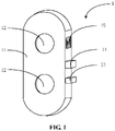
Fig. 1 is a three-dimensional view of one example of a camera assembly according to an embodiment of the present application. -
Fig. 2 is a front view of the camera assembly shown inFig. 1 . -
Fig. 3 is a rear view of one example of a mobile terminal according to an embodiment of the present application. -
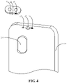
Fig. 4 is a three-dimensional view of the mobile terminal shown inFig. 3 , where in order to facilitate observation, a housing is subjected to perspective processing, and a camera assembly is also rotated. -
Fig. 5 is a front view of a magnetic suspension assembly of the mobile terminal shown inFig. 3 . -
Fig. 6 is a view of a circuit of controlling an electric current of an electromagnetic coil according to an embodiment of the present application. -
Fig. 7 is a rear view of the mobile terminal shown inFig. 3 , where a camera assembly is located in a receiving portion. -
Fig. 8 is a side view of the mobile terminal shown inFig. 3 , where a main body is inclined relative to a camera assembly. -
Fig. 9 is a front view of the mobile terminal shown inFig. 3 , where a lens faces forward. - Reference will now be made in detail to exemplary embodiments, examples of which are illustrated in the accompanying drawings. The following description refers to the accompanying drawings in which the same numbers in different drawings represent the same or similar elements unless otherwise represented. The implementations described in the following exemplary embodiments do not represent all the implementations consistent with the embodiments of the present application. Instead, they are merely examples of devices consistent with aspects of the embodiments of the present application as detailed in the appended claims.
- The terms used in the embodiments of the present application are for the purpose of describing the specific embodiments only, and are not intended to limit the embodiments of the present application. Unless otherwise defined, technical terms or scientific terms used in the embodiments of the present application should be understood in the ordinary meaning of those of ordinary skill in the art to which the invention pertains. The words "first", "second" and similar terms used in the specification and claims of the present application are not intended to indicate any order, quantity or importance, but only to distinguish different components. Similarly, the words "a" or "an" and the like do not denote a quantity limitation, but mean that there is at least one. "Multiple" or "several" means two or more than two. The similar words "including" or "comprising" and the like mean that elements or objects preceding "including" or "comprising" encompass elements or objects listed after "including" or "comprising" and their equivalents, and do not exclude other elements or objects. The similar words "connecting" or "connected" and the like are not limited to physical or mechanical connections, and may include electrical connections, whether direct or indirect. The singular forms "a", "the" and "this" used in the specification of the embodiments of the present application and the appended claims are also intended to include a plurality of forms unless the context clearly indicates otherwise. It should also be understood that the term "and/or" as used herein refers to and encompasses any or all possible combinations of one or more of the associated listed items.
- An embodiment of the present application provides a camera assembly for a mobile terminal, such as a mobile phone, a tablet computer, or a smart wearable device. The camera assembly includes a camera module, a first wireless transmission module and a first magnet. The first wireless transmission module may be electrically connected to the camera module and configured to transmit data. In the embodiments of the present application, since a camera assembly is provided with a first magnet, the camera assembly may be in a suspended state under a magnetic force applied to the first magnet; even if a main body of a mobile terminal slightly shakes or waggles, the first magnet may be still in an equally strong magnetic field. In this case, the magnetic force is not changed, so the camera assembly can remain stationary, thus ensuring good imaging quality. In addition, the camera assembly may be maintained in a suspended state to bring a new user experience. In the embodiment of the present application, the "magnet" may include a permanent magnet and an electromagnet, and the "magnetic force" may include a magnetic force generated by the permanent magnet, and also may include an electromagnetic force generated by the electromagnet.
- Referring to
Fig. 1 andFig. 2 , thecamera assembly 1 of the present embodiment includes acamera module 11, a firstwireless transmission module 13 connected to thecamera module 11, afirst magnet 14, and a wirelesspower receiving module 15. The "connection" here may be a direct connection, or may be an indirect connection through a connecting element, or may be embedding in a receiving space. The wirelesspower receiving module 15 may be electrically connected to thecamera module 11 and the firstwireless transmission module 13, respectively. Thefirst magnet 14 may be located between the firstwireless transmission module 13 and the wirelesspower receiving module 15. The wirelesspower receiving module 15 is configured to receive power and power thecamera module 11 and the firstwireless transmission module 13. Thecamera module 11 is configured to acquire an image. The firstwireless transmission module 13 is configured to be paired with a mobile terminal and perform data transmission, transmit the captured image to the mobile terminal, and receive various control signals from the mobile terminal. - The
camera module 11 may include alens 12, an optical lens, an imaging element, a circuit board, a motor, and other structures. The firstwireless transmission module 13 may be electrically connected to the circuit board of thecamera module 11. In the present embodiment, the number of thelenses 12 is two, and the twolenses 12 may be respectively a zoom lens and a telephoto lens. In other embodiments, the number of thecamera modules 11 may be one or two or more. - The first
wireless transmission module 13 may be, for example, a short-range millimeter wave wireless transmission module, a Near Field Communication (NFC) module, a Bluetooth module, a ZigBee module, a WiFi module, etc., and may perform wireless data transmission. In other embodiments, the firstwireless transmission module 13 may also be powered without the wirelesspower receiving module 15. For example, the firstwireless transmission module 13 may be an NFC module, and power may be supplied by an induced voltage of a radio frequency signal. - The first
wireless transmission module 13 may be, for example, a coil, and may receive power of the mobile terminal, that is, using an electromagnetic field to transmit power, which is similar to a transformer in principle. In other embodiments, the wirelesspower receiving module 15 may be replaced with a battery to directly provide power for thecamera module 11 and the firstwireless transmission module 13. - It can be understood that in order to avoid mutual influence of electromagnetic fields between the
first magnet 14 and the firstwireless transmission module 13, a metal shielding element may be disposed therebetween. - Since the data transmission and the power supply of the
camera assembly 1 are independent of other components, thecamera assembly 1 may be maintained in a suspended state under a magnetic force of an equally strong magnetic field received by thefirst magnet 14. Even if the main body of the mobile terminal slightly shakes or waggles during the photographing, thefirst magnet 14 may be maintained in the equally strong magnetic field. In this case, the magnetic force received by thefirst magnet 14 does not change, and thecamera assembly 1 can remain stationary, thereby ensuring the imaging quality of thecamera module 11. - In addition, an embodiment of the present application also provides a mobile terminal, which includes a main body and the camera assembly according to any of the foregoing embodiments. Referring to
Fig. 3 andFig. 4 , in the present embodiment, the mobile terminal may be, for example, a mobile phone, which may include amain body 2 and acamera assembly 1. Themain body 2 may include ahousing 21, a secondwireless transmission module 22 mounted in thehousing 21, amagnetic suspension assembly 23 and a wirelesspower transmitting module 24. Themagnetic suspension assembly 23 may be located between the secondwireless transmission module 22 and the wirelesspower transmitting module 24. The secondwireless transmission module 22 is configured to establish a communication connection with the firstwireless transmission module 13 to transmit data between themain body 2 and thecamera assembly 1. Themagnetic suspension assembly 23 is configured to generate a magnetic force acting on thefirst magnet 14 to maintain thecamera assembly 1 in a suspended state. The wirelesspower transmitting module 24 is configured to transmit power to the wirelesspower receiving module 15. - Of course, the mobile terminal further may include a display screen 25, a
processing unit 26, apower management unit 29, a storage unit, a battery, and other elements. Thehousing 21 is a housing of the mobile terminal. A transmission protocol of the secondwireless transmission module 22 may be consistent with a transmission protocol of the firstwireless transmission module 13, such as a short-range data transmission module, a Near Field Communication (NFC) module, a Bluetooth module, a ZigBee module, and a Wireless Fidelity (WiFi) module. The wirelesspower transmitting module 24 may be a coil. - The
magnetic suspension assembly 23 may include at least one electromagnetic coil. The at least one electromagnetic coil may be energized to generate a magnetic force for the magnet, and is configured to provide an equally strong magnetic field in a predetermined region. In the predetermined region, the magnetic field strength and the magnetic field direction may be the same or approximately the same. The magnetic force of the equally strong magnetic field acting on thefirst magnet 14 can maintain thecamera assembly 1 in a suspended state. - Referring to
Fig. 5 , themagnetic suspension assembly 23 may include a plurality ofelectromagnetic coils 231, arranged in a circumferential direction. In the present embodiment, the number of theelectromagnetic coils 231 is four, and when thecamera assembly 1 is in a suspended state, thefirst magnet 14 may be aligned with the center of themagnetic suspension assembly 23. Theelectromagnetic coil 231 may generate a magnetic force after being energized, in which case the magnetic force may be a repulsive force. The horizontal component force of the magnetic force may cause thecamera assembly 1 to remain stationary in a horizontal direction by zero force, and the vertical component of the magnetic force may be used to counteract the gravity, and may cause thecamera assembly 1 to remain stationary in a vertical direction by zero force. In other embodiments, themagnetic suspension assembly 23 may be composed of a plurality of permanent magnets or may be composed of a permanent magnet and an electromagnet, and also may enable thecamera assembly 1 to remain stationary by zero force. - When a user takes a picture using the mobile terminal, the
main body 2 of the mobile terminal may be slightly shaken, but the displacement of themagnetic suspension assembly 23 caused by the slight shake of themain body 2 may be almost negligible, and the basic equally strong magnetic field hardly changes, that is, thefirst magnet 14 is still in the equally strong magnetic field, the magnetic force received by thefirst magnet 14 does not change, and the magnetic force provided by themagnetic suspension assembly 23 still can make thecamera assembly 1 maintained in a suspended state and remain stationary. - Referring to
Fig. 5 andFig. 6 , preferably, themain body 2 further may include aposition sensor 27 electrically connected to theprocessing unit 26. The battery may supply power to eachelectromagnetic coil 231 through thepower management unit 29. Theposition sensor 27 is configured to acquire a position of thecamera assembly 1 relative to themain body 2, and theprocessing unit 26 may adjust an electric current of eachelectromagnetic coil 231 through thepower management unit 29 according to the position of thecamera body 1 relative to themain body 2, thereby adjusting the magnetic force received by thefirst magnet 14 and causing thecamera assembly 1 to remain stationary by zero resultant force. Even if themain body 2 has a large amplitude of shaking or waggling, thefirst magnet 14 may be disengaged from the above-mentioned equally strong magnetic field, and the adjusted magnetic force may enable thecamera assembly 1 to remain stationary. - In the present embodiment, the
position sensor 27 may include at least one of a gyroscope, a gravity sensor, or an acceleration sensor. Existing mobile terminals are usually equipped with sensors such as gyroscopes, gravity sensors or acceleration sensors, so that component cost and assembly cost may be not increased. - Referring to
Fig. 8 , when thecamera assembly 1 is in a suspended state, theposition sensor 27, such as a gyroscope, may detect an angle α between themain body 2 and thecamera assembly 1, and the angle α is an angle between a center line (or approximately a center line) of themain body 2 and a center line (or approximately a center line) of thecamera assembly 1. The center line may be a vertical center line or a horizontal center line. When the angle α is greater than a preset threshold, theprocessing unit 26 may control the electric current of the at least oneelectromagnetic coil 231 through thepower management unit 29, and change parameters such as the magnitude and/or direction of the magnetic force acting on thefirst magnet 14 by theelectromagnetic coil 231. The preset threshold may be experimentally determined, that is, when the angle α is not greater than the preset threshold, thecamera assembly 1 may be stably suspended above themain body 2. - For example, when an upper end of the
main body 2 is inclined toward the user, the angle α between themain body 2 and thecamera assembly 1 is greater than a preset threshold, the distance between theelectromagnetic coil 231 near the user side and thefirst magnet 14 may be reduced, the magnetic force generated by thefirst magnet 14 may be increased accordingly, and theprocessing unit 26 may lower the electric current of theelectromagnetic coil 231 near the user side or the electric current of theelectromagnetic coil 231 away from the user side by thepower management unit 29, thereby changing the magnetic force of theelectromagnetic coil 231 acting on thefirst magnet 14, so that thecamera assembly 1 may remain stationary by zero force, that is, still in a suspended state. - In one example, when the
camera assembly 1 is in a suspended state, theposition sensor 27 may detect an angle α between themain body 2 and thecamera assembly 1, and when the angle α is greater than a preset threshold, theprocessing unit 26 may change a direction of the electric current of theelectromagnetic coil 231 through thepower management unit 29, so that theelectromagnetic coil 231 may apply an attractive force to thefirst magnet 14, and thecamera assembly 1 may rotate for α and may be attached to the upper end of themain body 2 accordingly, thereby avoiding thecamera assembly 1 from being damaged by falling. It should be noted that the user may actively adjust the angle of themain body 2 based on a shooting angle, and thecamera assembly 1 may rotate to an angle consistent with themain body 2 to satisfy the user's requirement for the change of the shooting angle. - In the present embodiment, the
magnetic suspension assembly 23 may be disposed on either side of thehousing 21 and configured to generate a magnetic force acting on thefirst magnet 14 to make thecamera assembly 1 suspended above thehousing 21. In other embodiments, themagnetic suspension assembly 23 may be disposed on either side of thehousing 21, for example, on either side wall or either inner side wall, and the side wall may include upper, lower, left and right walls of thehousing 21. Thecamera assembly 1 may be suspended above themain body 2 regardless of how the user holds themain body 2. - Referring to
Fig. 3 ,Fig. 4 andFig. 7 , thehousing 21 may include a receivingportion 211 for receiving thecamera assembly 1. Themain body 2 further may include asecond magnet 28 mounted in thehousing 21. Thesecond magnet 28 may be disposed in or adjacent to the receivingportion 211. Thesecond magnet 28 is configured to generate a magnetic force for thefirst magnet 14 to hold thecamera assembly 1 in the receivingportion 211, that is, thecamera assembly 1 may be detachably connected with themain body 2 of the mobile terminal and may be fixed by magnetic attraction when being received in the receivingportion 211. Thecamera assembly 1 may be received in the receivingportion 211 when not in use. When being received in the receivingportion 211, thecamera assembly 1 may be taken for photographing or camera shooting. Since the distance between the firstwireless transmission module 13 and the secondwireless transmission module 22 is small, data may be transmitted therebetween. Another wirelesspower transmitting module 24 may be disposed in the receivingportion 211 and configured to transmit power to the wirelesspower receiving module 15 to supply power for thecamera module 11. - It is to be noted that when the
camera assembly 1 is in a suspended state, the twolenses 12 may be arranged in a horizontal direction; and when thecamera assembly 1 is located in thehousing portion 211, the twolenses 12 may be arranged in a vertical direction. A user may determine how to arrange thelenses 12 according to requirements, that is, arrange horizontally or vertically, and the user's requirement of horizontal or vertical shooting may be satisfied without rotating themain body 2. - Referring to
Fig. 3 andFig. 9 , thelens 12 of thecamera module 11 shown inFig. 3 faces the rear of themain body 2. A user may rotate thecamera assembly 1 for 180 degrees relative to its vertical center line, with thelens 12 of thecamera module 11 facing the front of themain body 2, i.e., facing the user, thereby allowing self-portraits or video chats. In other words, the mobile terminal according to the embodiment of the present application does not need to separately provide a front camera, thereby reducing the component cost and assembly cost of the front camera, and since the front camera is not needed additionally, it is beneficial to increase the screen ratio of the mobile terminal and obtain better user experience. In addition, the specifications of thecamera module 11 are comparable to those of a rear camera of the existing mobile terminal, so the imaging quality can be significantly better than that of the existing front camera. - The above is only the preferred embodiments of the present application and is not intended to limit the embodiments of the present application.
- In the embodiments of the present application, since a camera assembly is provided with a first magnet, the camera assembly can be maintained in a suspended state under a magnetic force applied to the first magnet; even if a main body of a mobile terminal slightly shakes or waggles, the first magnet can be still in an equally strong magnetic field. In this case, the magnetic force is not changed, so the camera assembly can remain stationary, thus ensuring good imaging quality. In addition, the camera assembly can be maintained in a suspended state to bring a new user experience.
Claims (5)
- A mobile terminal, comprising a main body (2) and a camera assembly (1), wherein the camera assembly (1) comprises:a camera module (11), configured to acquire an image;a first wireless transmission module (13), capable of being electrically connected to the camera module (11) and configured to transmit data; anda first magnet (14), configured to maintain the camera assembly (1) in a suspended state, wherein the main body (2) comprises a housing (21), a second wireless transmission module (22) and a magnetic suspension assembly (23),wherein the housing (21) comprises a receiving portion (211), the second wireless transmission module (22) is configured to establish a communication connection with the first wireless transmission module (13) to transmit data between the main body (2) and the camera assembly (1), and the magnetic suspension assembly (23) is configured to generate a magnetic force acting on the first magnet (14) to maintain the camera assembly (1) in a suspended state,wherein the camera assembly (1) is detachably connected with the main body (2);the mobile terminal comprises a second magnet (28) mounted in the housing (21), the second magnet (28) is configured to generate a magnetic force for the first magnet (14) to maintain the camera assembly (1) in the receiving portion (211),the magnetic suspension assembly (23) is disposed on either side of the main body (2) and configured to generate a magnetic force acting on the first magnet (14) to make the camera assembly (1) suspended above the housing (21); andwherein the magnetic suspension assembly (23) comprises at least one electromagnetic coil (231), wherein the at least one electromagnetic coil (231), upon energized, is capable of generating a magnetic force for the first magnet (14) to maintain the camera assembly (1) in a suspended state,wherein the main body (2) comprises a processing unit (26), a power management unit (29) and a position sensor (27), wherein the processing unit (26) is capable of being electrically connected to the position sensor (27) and the power management unit (29), respectively, wherein the position sensor (27) is configured to acquire a position of the camera assembly (1) relative to the main body (2),wherein the processing unit (26) is further configured to control an electric current of the at least one electromagnetic coil (231) through the power management unit (29) according to the position of the camera assembly (1) relative to the main body (2)wherein, when the camera assembly (1) is in a suspended state, the position sensor (27) is configured to detect an angle between the main body (2) and the camera assembly (1), andwherein, when the angle is greater than a preset threshold, the processing unit (26) is configured to change a direction of the electric current of the at least one electromagnetic coil (231) through the power management unit (29) to enable the at least one electromagnetic coil (231) to apply an attractive force to the first magnet (14) such that the camera assembly (1) is attached to the upper end of the main body (2).
- The mobile terminal of claim 1, wherein the camera module (11) comprises a wireless power receiving module (15), the main body (2) comprises a wireless power transmitting module (24), and the wireless power receiving module (15) is configured to receive power transmitted by the wireless power transmitting module (24) and supply power to the camera module (11).
- The mobile terminal of claim 1, wherein the magnetic suspension assembly (23) comprises a plurality of electromagnetic coils (231), arranged in a circumferential direction.
- The mobile terminal of claim 1, wherein the position sensor (27) comprises at least one of a gyroscope, a gravity sensor and an acceleration sensor.
- The mobile terminal of claim 1, wherein the camera assembly (1) further comprises a wireless power receiving module (15) or a battery for supplying power to the camera module (11).
Applications Claiming Priority (1)
| Application Number | Priority Date | Filing Date | Title |
|---|---|---|---|
| CN201910556329.9A CN112135015B (en) | 2019-06-25 | 2019-06-25 | Camera assembly and mobile terminal |
Publications (2)
| Publication Number | Publication Date |
|---|---|
| EP3758353A1 EP3758353A1 (en) | 2020-12-30 |
| EP3758353B1 true EP3758353B1 (en) | 2022-10-12 |
Family
ID=68766635
Family Applications (1)
| Application Number | Title | Priority Date | Filing Date |
|---|---|---|---|
| EP19213187.8A Active EP3758353B1 (en) | 2019-06-25 | 2019-12-03 | Camera assembly and mobile terminal |
Country Status (7)
| Country | Link |
|---|---|
| US (1) | US10924594B2 (en) |
| EP (1) | EP3758353B1 (en) |
| JP (1) | JP7012102B2 (en) |
| KR (1) | KR102300262B1 (en) |
| CN (1) | CN112135015B (en) |
| RU (1) | RU2725155C1 (en) |
| WO (1) | WO2020258596A1 (en) |
Families Citing this family (8)
| Publication number | Priority date | Publication date | Assignee | Title |
|---|---|---|---|---|
| KR102660800B1 (en) * | 2019-07-02 | 2024-04-26 | 삼성전자주식회사 | Electric device including rotation camera |
| CN111245984B (en) * | 2020-01-16 | 2022-03-11 | 维沃移动通信有限公司 | an electronic device |
| US11115512B1 (en) * | 2020-12-12 | 2021-09-07 | John G. Posa | Smartphone cases with integrated electronic binoculars |
| CN112492217B (en) * | 2020-12-17 | 2022-07-08 | 维沃移动通信有限公司 | Electronic apparatus and control method |
| CN113114815B (en) * | 2021-04-12 | 2023-08-08 | 维沃移动通信有限公司 | Electronic equipment |
| CN113329110A (en) | 2021-05-26 | 2021-08-31 | 武汉华星光电半导体显示技术有限公司 | Display device |
| USD1081759S1 (en) * | 2021-06-11 | 2025-07-01 | Beijing Xiaomi Mobile Software Co., Ltd. | Mobile terminal with camera |
| US12580602B2 (en) * | 2022-06-03 | 2026-03-17 | Apple Inc. | Accessory support devices for electronic devices |
Citations (3)
| Publication number | Priority date | Publication date | Assignee | Title |
|---|---|---|---|---|
| JP2003032344A (en) * | 2001-07-17 | 2003-01-31 | Kyocera Corp | Mobile terminal |
| US20150156898A1 (en) * | 2013-12-04 | 2015-06-04 | Lg Electronics Inc. | Mobile terminal |
| CN108881567A (en) * | 2018-09-26 | 2018-11-23 | 四川长虹电器股份有限公司 | A kind of screen smart-phone device comprehensively |
Family Cites Families (35)
| Publication number | Priority date | Publication date | Assignee | Title |
|---|---|---|---|---|
| JP2000175104A (en) | 1998-12-10 | 2000-06-23 | Matsushita Electric Ind Co Ltd | Imaging equipment |
| JP3448734B2 (en) * | 1999-06-28 | 2003-09-22 | 住友重機械工業株式会社 | Control device used for magnetic levitation system |
| RU2251221C2 (en) * | 2000-02-29 | 2005-04-27 | Киосера Корпорейшн | Portable data terminal, digital camera for portable data terminal and system, consisting of portable data terminal and digital camera |
| KR100617865B1 (en) * | 2004-03-05 | 2006-08-28 | 주식회사 팬택앤큐리텔 | Maglev type mobile communication terminal |
| US7679647B2 (en) * | 2004-07-21 | 2010-03-16 | Hewlett-Packard Development Company, L.P. | Flexible suspension for image stabilization |
| KR101420799B1 (en) * | 2007-11-30 | 2014-07-17 | 삼성전자주식회사 | Camera photographing method of mobile communication terminal using mobile communication terminal and conversion lens |
| US8073324B2 (en) * | 2009-03-05 | 2011-12-06 | Apple Inc. | Magnet array for coupling and aligning an accessory to an electronic device |
| KR101237933B1 (en) * | 2010-10-08 | 2013-03-05 | 우성곤 | Levitation display device |
| EP2607953A1 (en) * | 2011-12-23 | 2013-06-26 | Research In Motion Limited | Apparatus, and associated method, for affixing an external camera lens to a device having camera functionality |
| US20130177304A1 (en) * | 2012-01-11 | 2013-07-11 | Targus Group International, Inc. | Portable electronic device case accessory with interchangeable camera lens system |
| US9154677B2 (en) * | 2012-09-20 | 2015-10-06 | Apple Inc. | Camera accessory for angled camera viewing |
| US9497300B2 (en) * | 2014-03-28 | 2016-11-15 | Microsoft Technology Licensing, Llc | Input device attachment |
| KR101666271B1 (en) | 2014-05-30 | 2016-10-13 | 엘지전자 주식회사 | A levitation system for a mobile terminal |
| US9781345B1 (en) * | 2015-02-13 | 2017-10-03 | Apple Inc. | Dual camera magnet arrangement |
| KR20160105648A (en) * | 2015-02-27 | 2016-09-07 | 주식회사 유니온커뮤니티 | External-Optical Device for Mobile Terminal Equipped with Camera so as to Input Fingerprint, and Plate to Equip the External-Optical Device |
| KR102342558B1 (en) | 2015-06-05 | 2021-12-23 | 엘지전자 주식회사 | Camera module and mobile terminal having same |
| RU157466U1 (en) * | 2015-06-15 | 2015-12-10 | Арташес Валерьевич Икономов | OPTICAL BOX TO MOBILE PHONE TYPE SMARTPHONE |
| US10021280B2 (en) * | 2015-08-18 | 2018-07-10 | Apple Inc. | Camera module electrical architecture |
| KR101698866B1 (en) * | 2015-08-21 | 2017-01-24 | 주식회사 하이트론씨스템즈 | Magnetic Levitated artificial intelligent Camera Device |
| CN105323445B (en) * | 2015-09-21 | 2018-08-17 | 杭州觅睿科技有限公司 | Magnetic suspension video camera |
| CN205071146U (en) | 2015-10-27 | 2016-03-02 | 浙江宇视科技有限公司 | Magnetic control internet protocol camera |
| US9838064B2 (en) | 2015-10-30 | 2017-12-05 | Essential Products, Inc. | Wireless accessory bus for electronic devices |
| WO2017090478A1 (en) * | 2015-11-24 | 2017-06-01 | 富士フイルム株式会社 | Image blur correction device, lens device and imaging device |
| JP2019507996A (en) * | 2015-12-14 | 2019-03-22 | レッド.コム,エルエルシー | Modular digital camera and mobile phone |
| US10429666B1 (en) * | 2016-03-16 | 2019-10-01 | Apple Inc. | Camera actuator with magnet holder having magnetic field |
| CN106603777B (en) * | 2016-12-16 | 2020-03-13 | 上海摩软通讯技术有限公司 | Mobile terminal suspension device and system |
| CN106773451B (en) * | 2016-12-26 | 2021-07-27 | 格科微电子(上海)有限公司 | Implementation method of camera module optical anti-shake |
| CN206422839U (en) * | 2016-12-30 | 2017-08-18 | 南昌欧菲光科技有限公司 | Camera device |
| WO2018163037A1 (en) | 2017-03-07 | 2018-09-13 | Oganov Sergo | Video surveillance, monitoring and control device for a "smart home" system |
| US10419648B2 (en) * | 2017-04-08 | 2019-09-17 | Opkix, Inc. | Magnetic camera coupling system |
| CN207010798U (en) * | 2017-05-15 | 2018-02-13 | 深圳市沙堤科技有限公司 | A kind of electromagnetic levitation type desktop intelligent video camera head |
| US10187313B2 (en) * | 2017-06-01 | 2019-01-22 | Motorola Mobility Llc | Wireless communication device, peripheral, and method for managing values of operating parameters for a peripheral communication interface |
| CN207099173U (en) | 2017-07-17 | 2018-03-13 | 深圳市亿联智能有限公司 | A kind of new safety monitoring equipment of magnetic suspension |
| CN208581257U (en) * | 2018-03-13 | 2019-03-05 | Oppo广东移动通信有限公司 | Electronic equipment |
| CN109361968B (en) | 2018-09-29 | 2019-08-09 | 钟贵富 | Magnetic levitation speaker device with dynamic adjustment of fragrance |
-
2019
- 2019-06-25 CN CN201910556329.9A patent/CN112135015B/en active Active
- 2019-10-15 WO PCT/CN2019/111312 patent/WO2020258596A1/en not_active Ceased
- 2019-10-15 JP JP2019563800A patent/JP7012102B2/en active Active
- 2019-10-15 KR KR1020197033973A patent/KR102300262B1/en active Active
- 2019-10-15 RU RU2019137308A patent/RU2725155C1/en active
- 2019-11-16 US US16/686,146 patent/US10924594B2/en active Active
- 2019-12-03 EP EP19213187.8A patent/EP3758353B1/en active Active
Patent Citations (3)
| Publication number | Priority date | Publication date | Assignee | Title |
|---|---|---|---|---|
| JP2003032344A (en) * | 2001-07-17 | 2003-01-31 | Kyocera Corp | Mobile terminal |
| US20150156898A1 (en) * | 2013-12-04 | 2015-06-04 | Lg Electronics Inc. | Mobile terminal |
| CN108881567A (en) * | 2018-09-26 | 2018-11-23 | 四川长虹电器股份有限公司 | A kind of screen smart-phone device comprehensively |
Also Published As
| Publication number | Publication date |
|---|---|
| US10924594B2 (en) | 2021-02-16 |
| JP2021531668A (en) | 2021-11-18 |
| JP7012102B2 (en) | 2022-02-10 |
| CN112135015A (en) | 2020-12-25 |
| WO2020258596A1 (en) | 2020-12-30 |
| KR102300262B1 (en) | 2021-09-10 |
| RU2725155C1 (en) | 2020-06-30 |
| EP3758353A1 (en) | 2020-12-30 |
| US20200412853A1 (en) | 2020-12-31 |
| KR20210002322A (en) | 2021-01-08 |
| CN112135015B (en) | 2022-03-18 |
Similar Documents
| Publication | Publication Date | Title |
|---|---|---|
| EP3758353B1 (en) | Camera assembly and mobile terminal | |
| KR102693730B1 (en) | Optical image stabilization module and electronic device | |
| US9442363B2 (en) | Stereo camera module apparatus and method | |
| EP3236311B1 (en) | Stable and controllable shooting apparatus | |
| CN106470303B (en) | Camera Module Electrical Architecture | |
| US9531954B2 (en) | Lens array device | |
| KR20240166438A (en) | A lens moving unit, and camera module and optical instrument including the same | |
| EP3515058A1 (en) | Dual camera module, optical device, camera module, and method for operating camera module | |
| CN112788245B (en) | Camera module and electronic equipment | |
| CN209911671U (en) | A kind of anti-shake device and visual perception device | |
| US12581192B2 (en) | Electronic device and control method | |
| CN212411112U (en) | Electronic equipment and host | |
| US11528390B2 (en) | Magnetic levitation camera apparatus and live video system therewith | |
| CN113840074A (en) | Camera module anti-shake device and method and terminal | |
| KR101064131B1 (en) | Mini 3D Imaging Device | |
| KR20230112589A (en) | A lens moving unit, and camera module and optical instrument including the same | |
| KR20190133591A (en) | Aperture device, camera, and terminal including the same | |
| WO2022037313A1 (en) | Electronic device and main machine | |
| CN119233052B (en) | Actuator, camera module and electronic equipment | |
| CN114077282A (en) | Electronic equipment and host | |
| CN114079718A (en) | Image capturing method, storage medium, and electronic device | |
| KR20190133368A (en) | A lens moving apparatus, camera module and optical instrument including the same |
Legal Events
| Date | Code | Title | Description |
|---|---|---|---|
| PUAI | Public reference made under article 153(3) epc to a published international application that has entered the european phase |
Free format text: ORIGINAL CODE: 0009012 |
|
| STAA | Information on the status of an ep patent application or granted ep patent |
Free format text: STATUS: REQUEST FOR EXAMINATION WAS MADE |
|
| 17P | Request for examination filed |
Effective date: 20200902 |
|
| AK | Designated contracting states |
Kind code of ref document: A1 Designated state(s): AL AT BE BG CH CY CZ DE DK EE ES FI FR GB GR HR HU IE IS IT LI LT LU LV MC MK MT NL NO PL PT RO RS SE SI SK SM TR |
|
| AX | Request for extension of the european patent |
Extension state: BA ME |
|
| STAA | Information on the status of an ep patent application or granted ep patent |
Free format text: STATUS: EXAMINATION IS IN PROGRESS |
|
| 17Q | First examination report despatched |
Effective date: 20210316 |
|
| REG | Reference to a national code |
Ref country code: DE Ref legal event code: R079 Ref document number: 602019020494 Country of ref document: DE Free format text: PREVIOUS MAIN CLASS: H04N0005225000 Ipc: H04M0001724120 |
|
| GRAP | Despatch of communication of intention to grant a patent |
Free format text: ORIGINAL CODE: EPIDOSNIGR1 |
|
| STAA | Information on the status of an ep patent application or granted ep patent |
Free format text: STATUS: GRANT OF PATENT IS INTENDED |
|
| RIC1 | Information provided on ipc code assigned before grant |
Ipc: H04N 5/232 20060101ALI20220623BHEP Ipc: H04M 1/02 20060101ALI20220623BHEP Ipc: H04N 5/225 20060101ALI20220623BHEP Ipc: H04M 1/72412 20210101AFI20220623BHEP |
|
| INTG | Intention to grant announced |
Effective date: 20220726 |
|
| GRAS | Grant fee paid |
Free format text: ORIGINAL CODE: EPIDOSNIGR3 |
|
| GRAA | (expected) grant |
Free format text: ORIGINAL CODE: 0009210 |
|
| STAA | Information on the status of an ep patent application or granted ep patent |
Free format text: STATUS: THE PATENT HAS BEEN GRANTED |
|
| AK | Designated contracting states |
Kind code of ref document: B1 Designated state(s): AL AT BE BG CH CY CZ DE DK EE ES FI FR GB GR HR HU IE IS IT LI LT LU LV MC MK MT NL NO PL PT RO RS SE SI SK SM TR |
|
| REG | Reference to a national code |
Ref country code: GB Ref legal event code: FG4D |
|
| REG | Reference to a national code |
Ref country code: CH Ref legal event code: EP |
|
| REG | Reference to a national code |
Ref country code: DE Ref legal event code: R096 Ref document number: 602019020494 Country of ref document: DE |
|
| REG | Reference to a national code |
Ref country code: IE Ref legal event code: FG4D |
|
| REG | Reference to a national code |
Ref country code: AT Ref legal event code: REF Ref document number: 1524864 Country of ref document: AT Kind code of ref document: T Effective date: 20221115 |
|
| REG | Reference to a national code |
Ref country code: LT Ref legal event code: MG9D |
|
| REG | Reference to a national code |
Ref country code: NL Ref legal event code: MP Effective date: 20221012 |
|
| REG | Reference to a national code |
Ref country code: AT Ref legal event code: MK05 Ref document number: 1524864 Country of ref document: AT Kind code of ref document: T Effective date: 20221012 |
|
| PG25 | Lapsed in a contracting state [announced via postgrant information from national office to epo] |
Ref country code: NL Free format text: LAPSE BECAUSE OF FAILURE TO SUBMIT A TRANSLATION OF THE DESCRIPTION OR TO PAY THE FEE WITHIN THE PRESCRIBED TIME-LIMIT Effective date: 20221012 |
|
| PG25 | Lapsed in a contracting state [announced via postgrant information from national office to epo] |
Ref country code: SE Free format text: LAPSE BECAUSE OF FAILURE TO SUBMIT A TRANSLATION OF THE DESCRIPTION OR TO PAY THE FEE WITHIN THE PRESCRIBED TIME-LIMIT Effective date: 20221012 Ref country code: PT Free format text: LAPSE BECAUSE OF FAILURE TO SUBMIT A TRANSLATION OF THE DESCRIPTION OR TO PAY THE FEE WITHIN THE PRESCRIBED TIME-LIMIT Effective date: 20230213 Ref country code: NO Free format text: LAPSE BECAUSE OF FAILURE TO SUBMIT A TRANSLATION OF THE DESCRIPTION OR TO PAY THE FEE WITHIN THE PRESCRIBED TIME-LIMIT Effective date: 20230112 Ref country code: LT Free format text: LAPSE BECAUSE OF FAILURE TO SUBMIT A TRANSLATION OF THE DESCRIPTION OR TO PAY THE FEE WITHIN THE PRESCRIBED TIME-LIMIT Effective date: 20221012 Ref country code: FI Free format text: LAPSE BECAUSE OF FAILURE TO SUBMIT A TRANSLATION OF THE DESCRIPTION OR TO PAY THE FEE WITHIN THE PRESCRIBED TIME-LIMIT Effective date: 20221012 Ref country code: ES Free format text: LAPSE BECAUSE OF FAILURE TO SUBMIT A TRANSLATION OF THE DESCRIPTION OR TO PAY THE FEE WITHIN THE PRESCRIBED TIME-LIMIT Effective date: 20221012 Ref country code: AT Free format text: LAPSE BECAUSE OF FAILURE TO SUBMIT A TRANSLATION OF THE DESCRIPTION OR TO PAY THE FEE WITHIN THE PRESCRIBED TIME-LIMIT Effective date: 20221012 |
|
| PG25 | Lapsed in a contracting state [announced via postgrant information from national office to epo] |
Ref country code: RS Free format text: LAPSE BECAUSE OF FAILURE TO SUBMIT A TRANSLATION OF THE DESCRIPTION OR TO PAY THE FEE WITHIN THE PRESCRIBED TIME-LIMIT Effective date: 20221012 Ref country code: PL Free format text: LAPSE BECAUSE OF FAILURE TO SUBMIT A TRANSLATION OF THE DESCRIPTION OR TO PAY THE FEE WITHIN THE PRESCRIBED TIME-LIMIT Effective date: 20221012 Ref country code: LV Free format text: LAPSE BECAUSE OF FAILURE TO SUBMIT A TRANSLATION OF THE DESCRIPTION OR TO PAY THE FEE WITHIN THE PRESCRIBED TIME-LIMIT Effective date: 20221012 Ref country code: IS Free format text: LAPSE BECAUSE OF FAILURE TO SUBMIT A TRANSLATION OF THE DESCRIPTION OR TO PAY THE FEE WITHIN THE PRESCRIBED TIME-LIMIT Effective date: 20230212 Ref country code: HR Free format text: LAPSE BECAUSE OF FAILURE TO SUBMIT A TRANSLATION OF THE DESCRIPTION OR TO PAY THE FEE WITHIN THE PRESCRIBED TIME-LIMIT Effective date: 20221012 Ref country code: GR Free format text: LAPSE BECAUSE OF FAILURE TO SUBMIT A TRANSLATION OF THE DESCRIPTION OR TO PAY THE FEE WITHIN THE PRESCRIBED TIME-LIMIT Effective date: 20230113 |
|
| P01 | Opt-out of the competence of the unified patent court (upc) registered |
Effective date: 20230523 |
|
| REG | Reference to a national code |
Ref country code: DE Ref legal event code: R097 Ref document number: 602019020494 Country of ref document: DE |
|
| PG25 | Lapsed in a contracting state [announced via postgrant information from national office to epo] |
Ref country code: SM Free format text: LAPSE BECAUSE OF FAILURE TO SUBMIT A TRANSLATION OF THE DESCRIPTION OR TO PAY THE FEE WITHIN THE PRESCRIBED TIME-LIMIT Effective date: 20221012 Ref country code: RO Free format text: LAPSE BECAUSE OF FAILURE TO SUBMIT A TRANSLATION OF THE DESCRIPTION OR TO PAY THE FEE WITHIN THE PRESCRIBED TIME-LIMIT Effective date: 20221012 Ref country code: EE Free format text: LAPSE BECAUSE OF FAILURE TO SUBMIT A TRANSLATION OF THE DESCRIPTION OR TO PAY THE FEE WITHIN THE PRESCRIBED TIME-LIMIT Effective date: 20221012 Ref country code: DK Free format text: LAPSE BECAUSE OF FAILURE TO SUBMIT A TRANSLATION OF THE DESCRIPTION OR TO PAY THE FEE WITHIN THE PRESCRIBED TIME-LIMIT Effective date: 20221012 Ref country code: CZ Free format text: LAPSE BECAUSE OF FAILURE TO SUBMIT A TRANSLATION OF THE DESCRIPTION OR TO PAY THE FEE WITHIN THE PRESCRIBED TIME-LIMIT Effective date: 20221012 |
|
| REG | Reference to a national code |
Ref country code: CH Ref legal event code: PL |
|
| PLBE | No opposition filed within time limit |
Free format text: ORIGINAL CODE: 0009261 |
|
| STAA | Information on the status of an ep patent application or granted ep patent |
Free format text: STATUS: NO OPPOSITION FILED WITHIN TIME LIMIT |
|
| REG | Reference to a national code |
Ref country code: BE Ref legal event code: MM Effective date: 20221231 |
|
| PG25 | Lapsed in a contracting state [announced via postgrant information from national office to epo] |
Ref country code: SK Free format text: LAPSE BECAUSE OF FAILURE TO SUBMIT A TRANSLATION OF THE DESCRIPTION OR TO PAY THE FEE WITHIN THE PRESCRIBED TIME-LIMIT Effective date: 20221012 Ref country code: LU Free format text: LAPSE BECAUSE OF NON-PAYMENT OF DUE FEES Effective date: 20221203 Ref country code: AL Free format text: LAPSE BECAUSE OF FAILURE TO SUBMIT A TRANSLATION OF THE DESCRIPTION OR TO PAY THE FEE WITHIN THE PRESCRIBED TIME-LIMIT Effective date: 20221012 |
|
| 26N | No opposition filed |
Effective date: 20230713 |
|
| PG25 | Lapsed in a contracting state [announced via postgrant information from national office to epo] |
Ref country code: LI Free format text: LAPSE BECAUSE OF NON-PAYMENT OF DUE FEES Effective date: 20221231 Ref country code: IE Free format text: LAPSE BECAUSE OF NON-PAYMENT OF DUE FEES Effective date: 20221203 Ref country code: CH Free format text: LAPSE BECAUSE OF NON-PAYMENT OF DUE FEES Effective date: 20221231 |
|
| PG25 | Lapsed in a contracting state [announced via postgrant information from national office to epo] |
Ref country code: SI Free format text: LAPSE BECAUSE OF FAILURE TO SUBMIT A TRANSLATION OF THE DESCRIPTION OR TO PAY THE FEE WITHIN THE PRESCRIBED TIME-LIMIT Effective date: 20221012 Ref country code: BE Free format text: LAPSE BECAUSE OF NON-PAYMENT OF DUE FEES Effective date: 20221231 |
|
| PG25 | Lapsed in a contracting state [announced via postgrant information from national office to epo] |
Ref country code: CY Free format text: LAPSE BECAUSE OF FAILURE TO SUBMIT A TRANSLATION OF THE DESCRIPTION OR TO PAY THE FEE WITHIN THE PRESCRIBED TIME-LIMIT Effective date: 20221012 |
|
| PG25 | Lapsed in a contracting state [announced via postgrant information from national office to epo] |
Ref country code: MK Free format text: LAPSE BECAUSE OF FAILURE TO SUBMIT A TRANSLATION OF THE DESCRIPTION OR TO PAY THE FEE WITHIN THE PRESCRIBED TIME-LIMIT Effective date: 20221012 Ref country code: IT Free format text: LAPSE BECAUSE OF FAILURE TO SUBMIT A TRANSLATION OF THE DESCRIPTION OR TO PAY THE FEE WITHIN THE PRESCRIBED TIME-LIMIT Effective date: 20221012 Ref country code: HU Free format text: LAPSE BECAUSE OF FAILURE TO SUBMIT A TRANSLATION OF THE DESCRIPTION OR TO PAY THE FEE WITHIN THE PRESCRIBED TIME-LIMIT; INVALID AB INITIO Effective date: 20191203 |
|
| PG25 | Lapsed in a contracting state [announced via postgrant information from national office to epo] |
Ref country code: MC Free format text: LAPSE BECAUSE OF FAILURE TO SUBMIT A TRANSLATION OF THE DESCRIPTION OR TO PAY THE FEE WITHIN THE PRESCRIBED TIME-LIMIT Effective date: 20221012 |
|
| PG25 | Lapsed in a contracting state [announced via postgrant information from national office to epo] |
Ref country code: MC Free format text: LAPSE BECAUSE OF FAILURE TO SUBMIT A TRANSLATION OF THE DESCRIPTION OR TO PAY THE FEE WITHIN THE PRESCRIBED TIME-LIMIT Effective date: 20221012 |
|
| PG25 | Lapsed in a contracting state [announced via postgrant information from national office to epo] |
Ref country code: BG Free format text: LAPSE BECAUSE OF FAILURE TO SUBMIT A TRANSLATION OF THE DESCRIPTION OR TO PAY THE FEE WITHIN THE PRESCRIBED TIME-LIMIT Effective date: 20221012 |
|
| PG25 | Lapsed in a contracting state [announced via postgrant information from national office to epo] |
Ref country code: MT Free format text: LAPSE BECAUSE OF FAILURE TO SUBMIT A TRANSLATION OF THE DESCRIPTION OR TO PAY THE FEE WITHIN THE PRESCRIBED TIME-LIMIT Effective date: 20221012 |
|
| PG25 | Lapsed in a contracting state [announced via postgrant information from national office to epo] |
Ref country code: TR Free format text: LAPSE BECAUSE OF FAILURE TO SUBMIT A TRANSLATION OF THE DESCRIPTION OR TO PAY THE FEE WITHIN THE PRESCRIBED TIME-LIMIT Effective date: 20221012 |
|
| PGFP | Annual fee paid to national office [announced via postgrant information from national office to epo] |
Ref country code: DE Payment date: 20251126 Year of fee payment: 7 |
|
| PGFP | Annual fee paid to national office [announced via postgrant information from national office to epo] |
Ref country code: GB Payment date: 20251127 Year of fee payment: 7 |
|
| PGFP | Annual fee paid to national office [announced via postgrant information from national office to epo] |
Ref country code: FR Payment date: 20251124 Year of fee payment: 7 |