EP3758344A1 - Screen component and mobile terminal - Google Patents
Screen component and mobile terminal Download PDFInfo
- Publication number
- EP3758344A1 EP3758344A1 EP19212565.6A EP19212565A EP3758344A1 EP 3758344 A1 EP3758344 A1 EP 3758344A1 EP 19212565 A EP19212565 A EP 19212565A EP 3758344 A1 EP3758344 A1 EP 3758344A1
- Authority
- EP
- European Patent Office
- Prior art keywords
- movable member
- coil
- screen
- screen body
- screen component
- Prior art date
- Legal status (The legal status is an assumption and is not a legal conclusion. Google has not performed a legal analysis and makes no representation as to the accuracy of the status listed.)
- Granted
Links
Images




Classifications
-
- H—ELECTRICITY
- H04—ELECTRIC COMMUNICATION TECHNIQUE
- H04M—TELEPHONIC COMMUNICATION
- H04M1/00—Substation equipment, e.g. for use by subscribers
- H04M1/02—Constructional features of telephone sets
- H04M1/03—Constructional features of telephone transmitters or receivers, e.g. telephone hand-sets
-
- H—ELECTRICITY
- H04—ELECTRIC COMMUNICATION TECHNIQUE
- H04R—LOUDSPEAKERS, MICROPHONES, GRAMOPHONE PICK-UPS OR LIKE ACOUSTIC ELECTROMECHANICAL TRANSDUCERS; ELECTRIC HEARING AIDS; PUBLIC ADDRESS SYSTEMS
- H04R15/00—Magnetostrictive transducers
-
- G—PHYSICS
- G06—COMPUTING OR CALCULATING; COUNTING
- G06F—ELECTRIC DIGITAL DATA PROCESSING
- G06F1/00—Details not covered by groups G06F3/00 - G06F13/00 and G06F21/00
- G06F1/16—Constructional details or arrangements
- G06F1/1613—Constructional details or arrangements for portable computers
- G06F1/1615—Constructional details or arrangements for portable computers with several enclosures having relative motions, each enclosure supporting at least one I/O or computing function
-
- B—PERFORMING OPERATIONS; TRANSPORTING
- B06—GENERATING OR TRANSMITTING MECHANICAL VIBRATIONS IN GENERAL
- B06B—METHODS OR APPARATUS FOR GENERATING OR TRANSMITTING MECHANICAL VIBRATIONS OF INFRASONIC, SONIC, OR ULTRASONIC FREQUENCY, e.g. FOR PERFORMING MECHANICAL WORK IN GENERAL
- B06B1/00—Methods or apparatus for generating mechanical vibrations of infrasonic, sonic, or ultrasonic frequency
- B06B1/02—Methods or apparatus for generating mechanical vibrations of infrasonic, sonic, or ultrasonic frequency making use of electrical energy
- B06B1/04—Methods or apparatus for generating mechanical vibrations of infrasonic, sonic, or ultrasonic frequency making use of electrical energy operating with electromagnetism
- B06B1/045—Methods or apparatus for generating mechanical vibrations of infrasonic, sonic, or ultrasonic frequency making use of electrical energy operating with electromagnetism using vibrating magnet, armature or coil system
-
- H—ELECTRICITY
- H04—ELECTRIC COMMUNICATION TECHNIQUE
- H04M—TELEPHONIC COMMUNICATION
- H04M1/00—Substation equipment, e.g. for use by subscribers
- H04M1/02—Constructional features of telephone sets
- H04M1/0202—Portable telephone sets, e.g. cordless phones, mobile phones or bar type handsets
- H04M1/026—Details of the structure or mounting of specific components
-
- H—ELECTRICITY
- H04—ELECTRIC COMMUNICATION TECHNIQUE
- H04M—TELEPHONIC COMMUNICATION
- H04M1/00—Substation equipment, e.g. for use by subscribers
- H04M1/02—Constructional features of telephone sets
- H04M1/0202—Portable telephone sets, e.g. cordless phones, mobile phones or bar type handsets
- H04M1/026—Details of the structure or mounting of specific components
- H04M1/0266—Details of the structure or mounting of specific components for a display module assembly
-
- H—ELECTRICITY
- H04—ELECTRIC COMMUNICATION TECHNIQUE
- H04R—LOUDSPEAKERS, MICROPHONES, GRAMOPHONE PICK-UPS OR LIKE ACOUSTIC ELECTROMECHANICAL TRANSDUCERS; ELECTRIC HEARING AIDS; PUBLIC ADDRESS SYSTEMS
- H04R1/00—Details of transducers, loudspeakers or microphones
- H04R1/02—Casings; Cabinets ; Supports therefor; Mountings therein
- H04R1/025—Arrangements for fixing loudspeaker transducers, e.g. in a box, furniture
-
- H—ELECTRICITY
- H04—ELECTRIC COMMUNICATION TECHNIQUE
- H04R—LOUDSPEAKERS, MICROPHONES, GRAMOPHONE PICK-UPS OR LIKE ACOUSTIC ELECTROMECHANICAL TRANSDUCERS; ELECTRIC HEARING AIDS; PUBLIC ADDRESS SYSTEMS
- H04R9/00—Transducers of moving-coil, moving-strip, or moving-wire type
- H04R9/02—Details
- H04R9/025—Magnetic circuit
-
- H—ELECTRICITY
- H04—ELECTRIC COMMUNICATION TECHNIQUE
- H04R—LOUDSPEAKERS, MICROPHONES, GRAMOPHONE PICK-UPS OR LIKE ACOUSTIC ELECTROMECHANICAL TRANSDUCERS; ELECTRIC HEARING AIDS; PUBLIC ADDRESS SYSTEMS
- H04R9/00—Transducers of moving-coil, moving-strip, or moving-wire type
- H04R9/06—Loudspeakers
-
- H—ELECTRICITY
- H04—ELECTRIC COMMUNICATION TECHNIQUE
- H04M—TELEPHONIC COMMUNICATION
- H04M1/00—Substation equipment, e.g. for use by subscribers
- H04M1/02—Constructional features of telephone sets
- H04M1/03—Constructional features of telephone transmitters or receivers, e.g. telephone hand-sets
- H04M1/035—Improving the acoustic characteristics by means of constructional features of the housing, e.g. ribs, walls, resonating chambers or cavities
-
- H—ELECTRICITY
- H04—ELECTRIC COMMUNICATION TECHNIQUE
- H04R—LOUDSPEAKERS, MICROPHONES, GRAMOPHONE PICK-UPS OR LIKE ACOUSTIC ELECTROMECHANICAL TRANSDUCERS; ELECTRIC HEARING AIDS; PUBLIC ADDRESS SYSTEMS
- H04R2499/00—Aspects covered by H04R or H04S not otherwise provided for in their subgroups
- H04R2499/10—General applications
- H04R2499/11—Transducers incorporated or for use in hand-held devices, e.g. mobile phones, PDA's, camera's
-
- H—ELECTRICITY
- H04—ELECTRIC COMMUNICATION TECHNIQUE
- H04R—LOUDSPEAKERS, MICROPHONES, GRAMOPHONE PICK-UPS OR LIKE ACOUSTIC ELECTROMECHANICAL TRANSDUCERS; ELECTRIC HEARING AIDS; PUBLIC ADDRESS SYSTEMS
- H04R2499/00—Aspects covered by H04R or H04S not otherwise provided for in their subgroups
- H04R2499/10—General applications
- H04R2499/15—Transducers incorporated in visual displaying devices, e.g. televisions, computer displays, laptops
Definitions
- the present invention belongs to the technical field of electronic devices and relates to a screen component and a mobile terminal.
- a mobile terminal such as a mobile phone or a tablet computer plays an increasingly important role in the daily life, and many designers also pay more and more attentions to user experiences in development of mobile terminals.
- a screen sound technology is adopted for the mobile terminal to overcome the shortcoming of a conventional moving-coil speaker, that is, the conventional moving-coil speaker requires formation of a hole in a middle frame component of a mobile terminal to allow the sound output.
- components configured to achieve the screen sound technology comprise a linear motor type exciter, a piezoelectric exciter, an electromagnetic suspension exciter or the like.
- a sound effect in a low frequency band is poor and a user experience is influenced.
- These components are low in electromagnetic efficiency, low in efficiency of converting electromagnetic energy of the components into kinetic energy and slow in response. Fabrication processes for the components such as the piezoelectric exciter and the electromagnetic suspension exciter are complex and have an extremely high requirement on fitting accuracy, which causes low yield and high production cost.
- the present invention provides a screen component and a mobile terminal.
- the present invention is implemented through the following technical solutions.
- a screen component which may comprise a screen body and at least one vibration assembly.
- the vibration assembly may comprise a movable member made from a giant magnetostrictive material and at least one coil surrounding the movable member. A part of the movable member is in contact with the screen body.
- the at least one coil forms a magnetic field when the coil is supplied with a input current.
- the movable member deforms under the effect of the magnetic field.
- the magnetic field changes according to a change in parameter of the input current.
- a deformation amount of the movable member changes according to the change in the magnetic field of the coil to drive the screen body to vibrate to output corresponding sound information by the screen component.
- a deformation direction of the movable member may be perpendicular to the screen body.
- the movable member may be positioned in a center of the coil.
- the vibration assembly may comprise a conduction member mounted at an output end of the movable member, and the conduction member may be in contact with the screen body and presses the screen body to be elastically deformed.
- a contact area of the conduction member and the screen body may be larger than an area of the output end of the movable member.
- the conduction member may be in the form of a plate structure, and the movable member may be connected to a center of the conduction member.
- the conduction member may be glued to the movable member.
- the vibration assembly may further comprise a protective cover fixedly connected to the conduction member, and the protective cover may be arranged to cover the movable member.
- the protective cover may be detachably connected with the conduction member; or, the protective cover may be integrally formed with the conduction member.
- the protective cover may comprise a limiting portion and a collar portion surrounding the limiting portion.
- the movable member may abuts against the limiting portion and be limited in a region surrounded by the collar portion.
- At least a part of the protective cover may be inserted into a region enclosed by the coil and spaced from the coil by a preset distance.
- the vibration assembly may comprise a magnetic shield cover arranged to encircle the coil.
- the magnetic shield cover may be configured to limit a relative position between the movable member and the screen body. One end of the movable member may extend beyond the magnetic shield cover.
- the magnetic shield cover may comprise a bottom wall and a shielding wall surrounding the bottom wall.
- the coil and the movable member may be positioned in a region surrounded by the shielding wall and be limited by the bottom wall.
- a mobile terminal which may comprise: a processor and a memory configured to store a processor executable instruction.
- the mobile terminal may further comprise the abovementioned screen component, and a coil may be in communication connection with the processor.
- the mobile terminal may further comprise a middle frame component, and the screen body and the vibration assembly may be detachably connected to the middle frame component.
- the movable member made from the giant magnetostrictive material is axially telescopically deformed to form a thrust acting on the screen body, and the screen body is subjected to the strong thrust.
- the movable member is approximately linearly deformed under the effect of the magnetic field of the coil, so that a size of the whole vibration assembly may be reduced, overall layout of the screen component may be facilitated, and a stereoscopic effect of an output sound effect may be improved.
- the vibration assembly directly acts on the screen body and synchronously changes along with a current signal output by an audio circuit module, so that a sound output by the screen component is low in distortion and high in frequency response, and a good user experience is provided. Moreover, the vibration assembly is directly attached to the screen body, so that an assembly requirement and a fit tolerance requirement are low, a product defective rate is reduced, and production cost is reduced.
- Vibration assembly 10 Vibration assembly 10; movable member 11; coil 12; conduction member 13; protective cover 14; limiting portion 141; collar portion 142; magnetic shield cover 15; bottom wall 151; shielding wall 152; screen body 20; middle frame component 30; mobile terminal 40; processing component 41; memory 42; power component 43; multimedia component 44; audio component 45; Input/Output (I/O) interface 46; sensor component 47; communication component 48; and processor 49.
- processing component 41 memory 42; power component 43; multimedia component 44; audio component 45; Input/Output (I/O) interface 46; sensor component 47; communication component 48; and processor 49.
- first, second, third and the like may be adopted to describe various information in the present invention, the information should not be limited to these terms. These terms are only adopted to distinguish the information of the same type.
- first information may also be called second information and, similarly, second information may also be called first information.
- second information may also be called first information.
- term “if” used here may be explained as “while” or “when” or “responsive to determining”, which depends on the context.
- a giant magnetostrictive material refers to a magnetostrictive material with an extremely great magnetostriction coefficient. Dimensional expansion and contraction of the giant magnetostrictive material may proportionally change along with an applied magnetic field, and the magnetostriction coefficient thereof is far greater than that of a conventional magnetostrictive material.
- the giant magnetostrictive material has the following characteristics. 1: The magnetostriction coefficient of the giant magnetostrictive material is great, and is few tens times larger than that of a material such as Fe and Ni, and is 3 to 5 times larger than that of piezoelectric ceramics. 2: Energy conversion efficiency of the giant magnetostrictive material is 49% to 56%, while that of the piezoelectric ceramics is 23% to 52%. 3: An energy density of the giant magnetostrictive material is high, and is 400 to 800 times larger than that of Ni and is 12 to 38 times larger than that of the piezoelectric ceramics. 4: Response time for formation of a magnetostrictive effect is short, and a stress effect is formed almost at the same time of magnetization.
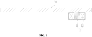
- Fig. 1 is a sectional structure diagram of a screen component, according to an exemplary example.
- Fig. 2 is a sectional structure diagram of a vibration assembly 10 according to an exemplary example, in which a movable member 11 of the vibration assembly vibrates under the effect of a magnetic field of a coil 12.
- the screen component comprises a screen body 20 and at least one vibration assembly 10
- the vibration assembly 10 comprises a movable member 11 made from a giant magnetostrictive material and at least one coil 12 surrounding the movable member 11.
- the at least one coil 12 forms a magnetic field when the coil 12 is supplied with an input current.
- the movable member 11 deforms under the effect of the magnetic field.
- the magnetic field changes according to a change in parameter of the input current.
- a deformation amount of the movable member 11 changes according to the change in the magnetic field of the coil 12 to drive the screen body 20 to vibrate to output corresponding sound information by the screen component.
- the coil 12 generates the magnetic field when being energized.
- a parameter of the magnetic field changes according to a change in the current parameter, and the parameter of the magnetic field and the current parameter change synchronously.
- the screen component may be applied to an electronic device.
- the coil 12 is electrically connected to an audio circuit module of the electronic device such that the change in the current parameter of the coil 12 is consistent with a change in an audio frequency, and that amount of the expansion and contraction of the movable member 11 corresponds to the change in an audio frequency during the change of the magnetic field.
- the movable member 11 is in contact with a surface of the screen body 20.
- a change direction of the expansion and contraction of the movable member 11 is a linear reciprocating expansion and contraction movement, the movement direction is stable, and the expansion and contraction is controllable.
- the movable member 11 made from the giant magnetostrictive material is telescopically deformed in an axial direction, to apply a thrust onto the screen body 20, and thus the screen body 20 is subjected to the strong thrust.
- the movable member 11 is approximately linearly deformed under the effect of the magnetic field of the coil 12, so that a size of the whole vibration assembly 10 may be reduced, overall layout of the screen component may be facilitated, and a stereoscopic effect of an output sound effect may be improved.
- the vibration assembly 10 directly acts on the screen body 20 and synchronously changes with a current signal output by an audio circuit module, so that a sound output by the screen component is low in distortion and high in frequency response, and a user experience is improved. Moreover, the vibration assembly 10 is in directly contact with the screen body 20, so that an assembly requirement and a fit tolerance requirement are low, a product defective rate is reduced, and production cost is reduced.
- the screen body 20 is elastically deformed under the effect of the thrust of the movable member 11, such that the screen body 20 vibrates and outputs the sound information.
- a contact position of the movable member 11 and the screen body 20 may be arranged according to a spatial layout requirement, and a deformation direction of the movable member 11 is at a preset angle with respect to the screen body 20, for example, the deformation direction of is at an angle of 45 degrees, 60 degrees, 85 degrees or 90 degrees with respect to the screen body.
- a deformation direction of the movable member 11 is perpendicular to the screen body 20 such that a deformation of the movable member 11 is the same as a deformation of the screen body 20, a sound distortion is low and a frequency response is high.
- the movable member 11 is positioned at a center of the coil 12.
- the coil 12 is in the form of an annular structure, to surround the movable member 11.
- the movable member 11 is positioned at the center of the coil 12 and is evenly subjected to the magnetic field in each direction, the deformation of the movable member 11 is concentrated in an axial direction, and thus an expansion and contraction direction may be well controlled.
- the movable member 11 is of a pillar structure, the contact position of the movable member with the screen body 20 is controllable, and positioning accuracy is high.
- the movable member 11 may also be a pillar structure having a cylindrical section, prismatic section or another sectional shape.
- a shape of the movable member 11 is not limited to a regular pillar structure and may also be another shape such as an irregular pillar structure with different sectional dimensions.
- One or more spaced vibration assemblies 10 are assembled on the screen body 20, so that a sound output position of the screen component may be flexibly adjusted and high design flexibility is ensured.
- Multiple vibration assemblies 10 spaced from each other are assembled on the screen body 20, so that an output range of the sound information may be extended, and a good sound output effect such as a good stereoscopic sound output effect may be achieved.
- the movable member 11 may be directly abutted against the screen body 20 to thrust the screen body 20 to be elastically deformed and to vibrate.
- the movable member may also transmit a driving force to the screen body 20 through an intermediate member to thrust the screen body 20 to be elastically deformed and to vibrate.
- the vibration assembly 10 comprises a conduction member 13 mounted at an output end of the movable member 11, and the conduction member 13 is in contact with the screen body 20 and thrusts the screen body 20 to be elastically deformed.
- the conduction member 13 is positioned between the screen body 20 and the movable member 11 to transmit the driving force as the intermediate structural member, so that an operating position and operating angle between the screen body 20 and the movable member 11 may be adjusted, and flexibility in spatial layout between the vibration assembly 10 and the screen body 20 may be improved.
- the conduction member 13 is configured to change a direction of an acting force of the vibration assembly 10, so as to be adapted to the spatial layout of the vibration assembly 10.
- the conduction member 13 may be a wedge block moving structure, a hinge rotating mechanism or a connecting rod mechanism.
- the conduction member 13 is configured to change the contact position and contact area of the vibration assembly 10 and the screen body 20 to improve the sound effect output by the screen component and prolong service life of the screen component.
- a contact area of the conduction member 13 and the screen body 20 is larger than an area of the output end of the movable member 11.
- the conduction member 13 is connected to the output end of the movable member 11 to ensure that the displacement of conduction member is same as the movable member.
- a contact area of the conduction member 13 and the screen body 20 is larger, so that concentration of the thrust on the screen body 20 is avoided, and evener stress is ensured.
- a contact area of the movable member 11 and the screen body 20 is enlarged by the conduction member 13, so that a vibration frequency of the screen body 20 may be reduced and improved, the screen body 20 may vibrate more stably, and the sound effect output by the screen component may be better.
- the conduction member 13 is in contact with the screen body 20 and transmits the driving force transmitted by the movable member 11 to the screen body 20, to cause the screen body and the movable member to move synchronously.
- the conduction member 13 is glued to the screen body 20 through an adhesive, to attach the surface of the conduction member with the surface of screen body.
- the conduction member 13 is closely attached to the screen body 20 through the adhesive without any movement gap therebetween, so that the conduction member 13 and the screen body 20 are synchronously elastically deformed, and thus a wide deformation range and close contact is achieved.
- the conduction member 13 is in the form of a plate structure, and the movable member 11 is connected to a center of the conduction member 13.
- the conduction member 13 is in the form of a thin-walled structure and may be gradually elastically deformed from the center to the periphery, and the deformation range is wide.
- the conduction member 13 is a circular plate structure, and the movable member 11 is connected to the center of the conduction member 13, such that the conduction member 13 is subjected to the same force in each direction.
- the conduction member 13 is in form of a square plate structure, and the movable member 11 is connected to an intersection of diagonals of the conduction member 13, such that the conduction member 13 is subjected to the force that is symmetrically distributed and even.
- the conduction member 13 is in form of the plate structure and may evenly transmit the driving force of the movable member 11 to the screen body 20 with a relatively large contact area, a transmission effect is good, the output sound information covers a wide frequency band, the sound distortion is low, and the frequency response is high.
- one side surface of the conduction member 13 is glued to the screen body 20, and the other side surface is connected with the movable member 11 to transmit the expansion and contraction of the movable member and the thrust generated by expansion and contraction movement to the screen body 20.
- the conduction member 13 is closely connected with the movable member 11 at a contact part of the movable member.
- the conduction member 13 is glued the movable member 11, so as to be fixed and form an integrated structure.
- the vibration assembly 10 further comprises a protective cover 14 fixedly connected to the conduction member 13, and the protective cover 14 is arranged to cover the movable member 11.
- the protective cover 14 is fixedly connected to the conduction member 13, and configured to limit a movement range of the movable member 11 to keep relative position between the movable member 11 and the conduction member 13 fixed. A range of the conduction member 13 subjected to the force is unified, and a limiting effect on the movable member 11 is good.
- the protective cover 14 is provided with a hollow limiting space, and the protective cover 14 is arranged to cover the movable member 11. The output end of the movable member 11 is limited in the limiting space to limit circumferential offset of the movable member 11 and achieve high positioning accuracy.
- the protective cover 14 is fixedly connected to the conduction member 13 to form a whole structure.
- the protective cover 14 is detachably connected with the conduction member 13.
- the protective cover 14 and the conduction member 13 are arranged to be independent components, so that machining efficiency is improved.
- the protective cover 14 and the conduction member 13 are made into a whole structure by welding, adhesion through the adhesive and another machining process, and are high in connection firmness.
- the protective cover 14 is integrally formed with the conduction member 13.
- the protective cover 14 is formed at the conduction member 13 by an integral molding or over-molding process.
- the protective cover 14 and the conduction member 13 form a stepped structure, and the conduction member 13 is fixed to the screen body 20 and connected to the movable member 11 through the protective cover 14 in a limiting manner.
- the positioning accuracy is high, the transmission effect is good, and the output sound quality is high.
- the protective cover 14 is arranged to cover the movable member 11 to limit the movement range of the movable member 11 and protect the movable member 11.
- the protective cover 14 comprises a limiting portion 141 and a collar portion 142 surrounding the limiting portion 141.
- the movable member 11 is abutted against the limiting portion 141 and is limited in a region surrounded by the collar portion 142.
- the collar portion 142 is an annular or tubular protrusion.
- the limiting portion 141 is positioned at one end of the collar portion 142 and closes at least part of an opening of the collar portion 142.
- the movable member 11 is inserted into the region surrounded by the collar portion 142 and abutted against the limiting portion 141, to ensure that the output end of the movable member 11 is limited and protected by the protective cover 14 and achieve stable overall performance of the movable member 11 and the good output effect.
- the protective cover 14 is inserted into a region enclosed by the coil 12 and spaced from the coil 12 by a preset distance.
- the movable member 11 is positioned in the region surrounded by the coil 12 and may elastically expands and contracts under the effect of the magnetic field of the coil 12.
- the protective cover 14 is arranged to encircle the output end of the movable member 11 and extend into the region surrounded by the coil 12.
- the protective cover 14 is spaced from the coil 12, so that the protective cover 14 may move relative to the coil 12 during an expansion and contraction process of the movable member 11, and thus the movement flexibility is high.
- the protective cover 14 extends into the region surrounded by the coil 12, so that the cooperation range of the protective cover 14 and the movable member 11 may be extended, and contact stability of the protective cover and the movable member may be improved.
- a pre-pressure is exerted between the screen body 20 and the vibration assembly 10, and the pre-pressure is transmitted to the movable member 11 through the protective cover 14 to form the pre-pressure between the movable member 11 and the protective cover 14 to implement close contact therebetween and high vibration synchronism.
- the vibration assembly 10 comprises a magnetic shield cover 15 arranged to encircle coil 12, the magnetic shield cover 15 is configured to limit the relative position between the movable member 11 and the screen body 20. One end of the movable member 11 extends beyond the magnetic shield cover 15.
- the magnetic shield cover 15 is in the form of a rigid structure, is arranged to encircle the coil 12 and limits a mounting position of the movable member 11.
- the magnetic shield cover 15 may be fixed to a fixed frame to keep the relative position between the vibration assembly 10 and the screen body 20 fixed.
- the movable member 11 is limited in the coil 12, one end of the movable member is blocked by the magnetic shield cover 15, while the other end extends out of the magnetic shield cover 15 and extends outwards to be abutted against the screen body 20 and the protective cover 14, to limit the expansion and contraction direction of the movable member 11.
- the direction of the movable member 11 may be controlled well.
- the magnetic shield cover 15 is made from a magnetized steel material to shield the range of the magnetic field of the coil 12, so as to avoid influence of the magnetic field generated by the coil 12 on a region outside the magnetic shield cover 15 and make the range of the magnetic field controllable.
- the magnetic field acts on the movable member 11 in a concentrated manner to ensure that the movable member 11 may accurately expand and contract according to a change in the magnetic field, and thus high sensitivity is achieved.
- the magnetic shield cover 15 comprises a bottom wall 151 and a shielding wall 152 surrounding the bottom wall 151, and the coil 12 and the movable member 11 are positioned in region surrounded by the shielding wall 152 and limited by the bottom wall 151.
- the bottom wall 151 and the shielding wall 152 enclose a container-shaped surrounding region.
- the coil 12 and the movable member 11 are assembled at the magnetic shield cover 15 and at least partially positioned in the surrounding region. Convenience for mounting is ensured.
- the bottom wall 151 is configured to limit mounting positions of the coil 12 and the movable member 11 to achieve high accuracy of magnetized regions of the coil 12 and the movable member 11, and thus ensure that the movable member 11 may control the expansion and contraction of the output end according to the change in the magnetic field with high control accuracy.
- the screen component disclosed in the abovementioned example is applied to a mobile terminal to enable the mobile terminal to output sound information through the screen component, avoid formation of a structure such as a sound outlet in the mobile terminal and achieve attractive overall appearance.
- the mobile terminal comprises a processor and a memory configured to store a processor executable instruction.
- the mobile terminal further comprises the screen component disclosed in the abovementioned example.
- the coil 12 is in communication connection with the processor.
- the coil 12 may control a change in a magnetic field according to a change of a corresponding audio signal.
- the movable member 11 converts the change in the magnetic field into a driving force for driving a screen body 20 to generate sound. Energy conversion efficiency is high, and sound quality of a low frequency band is high.
- the mobile terminal further comprises a middle frame component 30, and the screen body 20 and a vibration assembly 10 are detachably connected to the middle frame component 30.
- a magnetic shield cover 15 is fixed to the middle frame component 30 and positioned in a region enclosed by the middle frame component 30.
- the screen body 20 closes an opening of the middle frame component 30 and is in contact with the vibration assembly 10.
- An expansion and contraction generated by the movable member 11 under the effect of the magnetic field of the coil 12 is directly transmitted to the screen body 20, so that high electromagnetic efficiency and low loss are ensured.
- the screen body 20 is glued to the middle frame component 30 through an adhesive.
- the adhesive has no compression or a preset compression, so that a fitting position between the screen body 20 and the middle frame component 30 is controllable, and the dimensional controllability of an expansion and contraction of the vibration assembly 10 is improved.
- the mobile terminal may be different electronic devices.
- the mobile terminal 40 may be a mobile phone, a computer, a digital broadcast terminal, a messaging device, a gaming console, a tablet, a medical device, exercise equipment, a personal digital assistant, a translator and the like.
- the mobile terminal 40 may comprise one or more of the following components: a processing component 41, a memory 42, a power component 43, a multimedia component 44, an audio component 45, an I/O interface 46, a sensor component 47, and a communication component 48.
- the processing component 41 typically controls overall operations of the mobile terminal 40, such as the operations associated with display, telephone calls, data communications, camera operations, and recording operations.
- the processing component 41 may comprise one or more processors 49 to execute instructions to perform all or part of the steps in the abovementioned method.
- the processing component 41 may comprise one or more modules which facilitate interaction between the processing component 41 and the other components.
- the processing component 41 may comprise a multimedia module to facilitate interaction between the multimedia component 44 and the processing component 41.
- the memory 42 is configured to store various types of data to support the operation of the mobile terminal 40. Examples of such data comprise instructions for any application programs or methods operated on the mobile terminal 40, contact data, phonebook data, messages, pictures, video, etc.
- the memory 42 may be implemented by any type of volatile or non-volatile memory devices, or a combination thereof, such as a Static Random Access Memory (SRAM) 42, an Electrically Erasable Programmable Read-Only Memory (EEPROM) 42, an Erasable Programmable Read-Only Memory (EPROM) 42, a Programmable Read-Only Memory (PROM) 42, a Read-Only Memory (ROM) 42, a magnetic memory 42, a flash memory 42, and a magnetic or optical disk.
- SRAM Static Random Access Memory
- EEPROM Electrically Erasable Programmable Read-Only Memory
- EPROM Erasable Programmable Read-Only Memory
- PROM Programmable Read-Only Memory
- ROM Read-Only Memory
- the power component 43 provides power for various components of the mobile terminal 40.
- the power component 43 may comprise a power management system, one or more power supplies, and other components associated with generation, management and distribution of power for the mobile terminal 40.
- the multimedia component 44 comprises a screen providing an output interface between the mobile terminal 40 and a user.
- the screen may comprise a Liquid Crystal Display (LCD) and a Touch Panel (TP). If the screen comprises the TP, the screen may be implemented as a touch screen to receive an input signal from the user.
- the TP comprises one or more touch sensors to sense touches, swipes and gestures on the TP. The touch sensors may not only sense a boundary of a touch or swipe action but also detect a duration and pressure associated with the touch or swipe action.
- the multimedia component 44 comprises a front camera and/or a rear camera. The front camera and/or the rear camera may receive external multimedia data when the mobile terminal 40 is in an operation mode, such as a photographing mode or a video mode. Each of the front camera and the rear camera may be a fixed optical lens system or have focusing and optical zooming capabilities.
- the audio component 45 is configured to output and/or input an audio signal.
- the audio component 45 comprises a Microphone (MIC), and the MIC is configured to receive an external audio signal when the mobile terminal 40 is in the operation mode, such as a call mode, a recording mode and a voice recognition mode.
- the received audio signal may further be stored in the memory 42 or sent through the communication component 48.
- the audio component 45 further comprises a speaker configured to output the audio signal.
- the I/O interface 46 provides an interface between the processing component 41 and a peripheral interface module, and the peripheral interface module may be a keyboard, a click wheel, a button and the like.
- the button may comprise, but not limited to: a home button, a volume button, a starting button and a locking button.
- the sensor component 47 comprises one or more sensors configured to provide status assessment in various aspects for the mobile terminal 40.
- the sensor component 47 may detect an on/off status of the device and relative positioning of components, such as a display and small keyboard of the mobile terminal 40, and the sensor component 47 may further detect a change in a position of the mobile terminal 40 or a component of the mobile terminal 40, presence or absence of contact between the user and the mobile terminal 40, orientation or acceleration/deceleration of the mobile terminal 40 and a change in temperature of the mobile terminal 40.
- the sensor component 47 may comprise a proximity sensor configured to detect presence of an object nearby without any physical contact.
- the sensor component 47 may also comprise a light sensor, such as a Complementary Metal Oxide Semiconductor (CMOS) or Charge Coupled Device (CCD) image sensor, configured for use in an imaging application.
- CMOS Complementary Metal Oxide Semiconductor
- CCD Charge Coupled Device
- the sensor component 47 may also comprise an acceleration sensor, a gyroscope sensor, a magnetic sensor, a pressure sensor or a temperature sensor.
- the communication component 48 is configured to facilitate wired or wireless communication between the mobile terminal 40 and other equipment.
- the mobile terminal 40 may access a communication-standard-based wireless network, such as Wireless Fidelity (WiFi), 2nd-Generation (2G), 3rd-Generation (3G), 4th-Generation (4G), 5th-Generation (5G) or a combination thereof.
- WiFi Wireless Fidelity
- 2G 2nd-Generation
- 3G 3rd-Generation
- 4G 4th-Generation
- 5G 5th-Generation
- the communication component 48 receives a broadcast signal or broadcast associated information from an external broadcast management system through a broadcast channel.
- the communication component 48 further comprises a Near Field Communication (NFC) module to facilitate short-range communication.
- NFC Near Field Communication
- the NFC module may be implemented based on a Radio Frequency Identification (RFID) technology, an Infrared Data Association (IrDA) technology, an Ultra-WideBand (UWB) technology, a Bluetooth (BT) technology and another technology.
- RFID Radio Frequency Identification
- IrDA Infrared Data Association
- UWB Ultra-WideBand
- BT Bluetooth
- the mobile terminal 40 may be implemented by one or more Application Specific Integrated Circuits (ASICs), Digital Signal Processors (DSPs) 49, Digital Signal Processing Devices (DSPDs), Programmable Logic Devices (PLDs), Field Programmable Gate Arrays (FPGAs), controllers, micro-controllers, microprocessors 49 or other electronic components, and is configured to execute the abovementioned method.
- ASICs Application Specific Integrated Circuits
- DSPs Digital Signal Processors
- DSPDs Digital Signal Processing Devices
- PLDs Programmable Logic Devices
- FPGAs Field Programmable Gate Arrays
- controllers micro-controllers, microprocessors 49 or other electronic components, and is configured to execute the abovementioned method.
Landscapes
- Engineering & Computer Science (AREA)
- Signal Processing (AREA)
- Physics & Mathematics (AREA)
- Acoustics & Sound (AREA)
- Theoretical Computer Science (AREA)
- Computer Hardware Design (AREA)
- General Physics & Mathematics (AREA)
- General Engineering & Computer Science (AREA)
- Human Computer Interaction (AREA)
- Mathematical Physics (AREA)
- Electromagnetism (AREA)
- Mechanical Engineering (AREA)
- Telephone Set Structure (AREA)
- Apparatuses For Generation Of Mechanical Vibrations (AREA)
Abstract
Description
- The present invention belongs to the technical field of electronic devices and relates to a screen component and a mobile terminal.
- A mobile terminal such as a mobile phone or a tablet computer plays an increasingly important role in the daily life, and many designers also pay more and more attentions to user experiences in development of mobile terminals. For example, in order to meet a demand of high screen-to-body ratio that a user of a mobile phone pursues and to implement a holeless design of appearance of the mobile phone, a screen sound technology is adopted for the mobile terminal to overcome the shortcoming of a conventional moving-coil speaker, that is, the conventional moving-coil speaker requires formation of a hole in a middle frame component of a mobile terminal to allow the sound output.
- In a related art, components configured to achieve the screen sound technology comprise a linear motor type exciter, a piezoelectric exciter, an electromagnetic suspension exciter or the like. However, when these components are applied to a mobile terminal, a sound effect in a low frequency band is poor and a user experience is influenced. These components are low in electromagnetic efficiency, low in efficiency of converting electromagnetic energy of the components into kinetic energy and slow in response. Fabrication processes for the components such as the piezoelectric exciter and the electromagnetic suspension exciter are complex and have an extremely high requirement on fitting accuracy, which causes low yield and high production cost.
- In view of this, the present invention provides a screen component and a mobile terminal.
- Specifically, the present invention is implemented through the following technical solutions.
- According to a first aspect of examples of the present invention, a screen component is provided, which may comprise a screen body and at least one vibration assembly. The vibration assembly may comprise a movable member made from a giant magnetostrictive material and at least one coil surrounding the movable member. A part of the movable member is in contact with the screen body.
- The at least one coil forms a magnetic field when the coil is supplied with a input current. The movable member deforms under the effect of the magnetic field. The magnetic field changes according to a change in parameter of the input current. A deformation amount of the movable member changes according to the change in the magnetic field of the coil to drive the screen body to vibrate to output corresponding sound information by the screen component.
- In an example, a deformation direction of the movable member may be perpendicular to the screen body.
- In an example, the movable member may be positioned in a center of the coil.
- In an example, the vibration assembly may comprise a conduction member mounted at an output end of the movable member, and the conduction member may be in contact with the screen body and presses the screen body to be elastically deformed.
- In an example, a contact area of the conduction member and the screen body may be larger than an area of the output end of the movable member.
- In an example, the conduction member may be in the form of a plate structure, and the movable member may be connected to a center of the conduction member.
- In an example, the conduction member may be glued to the movable member.
- In an example, the vibration assembly may further comprise a protective cover fixedly connected to the conduction member, and the protective cover may be arranged to cover the movable member.
- In an example, the protective cover may be detachably connected with the conduction member; or, the protective cover may be integrally formed with the conduction member.
- In an example, the protective cover may comprise a limiting portion and a collar portion surrounding the limiting portion. The movable member may abuts against the limiting portion and be limited in a region surrounded by the collar portion.
- In an example, at least a part of the protective cover may be inserted into a region enclosed by the coil and spaced from the coil by a preset distance.
- In an example, there may be a pre-pressure between the protective cover and the movable member.
- In an example, the vibration assembly may comprise a magnetic shield cover arranged to encircle the coil. The magnetic shield cover may be configured to limit a relative position between the movable member and the screen body. One end of the movable member may extend beyond the magnetic shield cover.
- In an example, the magnetic shield cover may comprise a bottom wall and a shielding wall surrounding the bottom wall. The coil and the movable member may be positioned in a region surrounded by the shielding wall and be limited by the bottom wall.
- According to a second aspect of the examples of the present invention, a mobile terminal is provided, which may comprise: a processor and a memory configured to store a processor executable instruction. The mobile terminal may further comprise the abovementioned screen component, and a coil may be in communication connection with the processor.
- In an example, the mobile terminal may further comprise a middle frame component, and the screen body and the vibration assembly may be detachably connected to the middle frame component.
- The technical solutions provided by examples of the present invention may have the following beneficial effects.
- The movable member made from the giant magnetostrictive material is axially telescopically deformed to form a thrust acting on the screen body, and the screen body is subjected to the strong thrust. The movable member is approximately linearly deformed under the effect of the magnetic field of the coil, so that a size of the whole vibration assembly may be reduced, overall layout of the screen component may be facilitated, and a stereoscopic effect of an output sound effect may be improved. The vibration assembly directly acts on the screen body and synchronously changes along with a current signal output by an audio circuit module, so that a sound output by the screen component is low in distortion and high in frequency response, and a good user experience is provided. Moreover, the vibration assembly is directly attached to the screen body, so that an assembly requirement and a fit tolerance requirement are low, a product defective rate is reduced, and production cost is reduced.
- It is to be understood that the above general descriptions and detailed descriptions below are only exemplary and explanatory and not intended to limit the present invention.
-
-
Fig. 1 is a sectional structure diagram of a screen component, according to an exemplary example. -
Fig. 2 is a sectional structure diagram of a vibration assembly of which a movable member vibrates under the effect of a magnetic field of a coil, according to an exemplary example. -
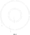
Fig. 3 is a top view of a circular vibration assembly, according to an exemplary example. -
Fig. 4 is a sectional structure diagram of a vibration assembly with a conduction member, according to an exemplary example. -
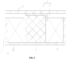
Fig. 5 is a structure diagram of a vibration assembly with a conduction member and a protective cover, according to an exemplary example. -
Fig. 6 is a structure diagram of a screen component mounted at a middle frame component, according to an exemplary example. -
Fig. 7 is a schematic block diagram of a mobile terminal, according to an exemplary example. - List of reference symbols:
Vibration assembly 10;movable member 11;coil 12;conduction member 13;protective cover 14; limitingportion 141;collar portion 142;magnetic shield cover 15;bottom wall 151;shielding wall 152;screen body 20;middle frame component 30;mobile terminal 40;processing component 41;memory 42;power component 43;multimedia component 44;audio component 45; Input/Output (I/O)interface 46;sensor component 47;communication component 48; andprocessor 49. - Reference will now be made in detail to exemplary examples, examples of which are illustrated in the accompanying drawings. The following description refers to the accompanying drawings in which the same numbers in different drawings represent the same or similar elements unless otherwise represented. The implementations set forth in the following description of exemplary examples do not represent all implementations consistent with the present invention. Instead, they are merely examples of apparatuses and methods consistent with aspects related to the present invention as recited in the appended claims.
- Terms used in the present invention are only adopted for the purpose of describing specific examples and not intended to limit the present invention. "A/an", "said" and "the" in a singular form in the present invention and the appended claims are also intended to comprise a plural form, unless other meanings are clearly denoted throughout the present invention. It is also to be understood that term "and/or" used in the present invention refers to and comprises one or any or all possible combinations of multiple associated items that are listed.
- It is to be understood that, although terms first, second, third and the like may be adopted to describe various information in the present invention, the information should not be limited to these terms. These terms are only adopted to distinguish the information of the same type. For example, without departing from the scope of the present invention, first information may also be called second information and, similarly, second information may also be called first information. For example, term "if" used here may be explained as "while" or "when" or "responsive to determining", which depends on the context.
- A giant magnetostrictive material refers to a magnetostrictive material with an extremely great magnetostriction coefficient. Dimensional expansion and contraction of the giant magnetostrictive material may proportionally change along with an applied magnetic field, and the magnetostriction coefficient thereof is far greater than that of a conventional magnetostrictive material.
- The giant magnetostrictive material has the following characteristics. 1: The magnetostriction coefficient of the giant magnetostrictive material is great, and is few tens times larger than that of a material such as Fe and Ni, and is 3 to 5 times larger than that of piezoelectric ceramics. 2: Energy conversion efficiency of the giant magnetostrictive material is 49% to 56%, while that of the piezoelectric ceramics is 23% to 52%. 3: An energy density of the giant magnetostrictive material is high, and is 400 to 800 times larger than that of Ni and is 12 to 38 times larger than that of the piezoelectric ceramics. 4: Response time for formation of a magnetostrictive effect is short, and a stress effect is formed almost at the same time of magnetization. 5: Compressive strength and a bearing capacity of the giant magnetostrictive material are high, and thus the giant magnetostrictive material can work in a strong pressure environment. 6: A working frequency band is wide, and the giant magnetostrictive material is applied not only to a low frequency below hundreds of Hz, but also to an ultrahigh frequency.
-
Fig. 1 is a sectional structure diagram of a screen component, according to an exemplary example.Fig. 2 is a sectional structure diagram of avibration assembly 10 according to an exemplary example, in which amovable member 11 of the vibration assembly vibrates under the effect of a magnetic field of acoil 12. As shown inFig. 1 andFig. 2 , the screen component comprises ascreen body 20 and at least onevibration assembly 10, thevibration assembly 10 comprises amovable member 11 made from a giant magnetostrictive material and at least onecoil 12 surrounding themovable member 11. The at least onecoil 12 forms a magnetic field when thecoil 12 is supplied with an input current. Themovable member 11 deforms under the effect of the magnetic field. The magnetic field changes according to a change in parameter of the input current. A deformation amount of themovable member 11 changes according to the change in the magnetic field of thecoil 12 to drive thescreen body 20 to vibrate to output corresponding sound information by the screen component. - The
coil 12 generates the magnetic field when being energized. A parameter of the magnetic field changes according to a change in the current parameter, and the parameter of the magnetic field and the current parameter change synchronously. The screen component may be applied to an electronic device. In the electronic device, thecoil 12 is electrically connected to an audio circuit module of the electronic device such that the change in the current parameter of thecoil 12 is consistent with a change in an audio frequency, and that amount of the expansion and contraction of themovable member 11 corresponds to the change in an audio frequency during the change of the magnetic field. Themovable member 11 is in contact with a surface of thescreen body 20. When amount of the expansion and contraction of themovable member 11 changes, thescreen body 20 is elastically deformed under the effect of a thrust of themovable member 11 and vibrates according to the change in audio frequency, to enable the screen component to output corresponding sound information with a good sound output effect. A change direction of the expansion and contraction of themovable member 11 is a linear reciprocating expansion and contraction movement, the movement direction is stable, and the expansion and contraction is controllable. - The
movable member 11 made from the giant magnetostrictive material is telescopically deformed in an axial direction, to apply a thrust onto thescreen body 20, and thus thescreen body 20 is subjected to the strong thrust. Themovable member 11 is approximately linearly deformed under the effect of the magnetic field of thecoil 12, so that a size of thewhole vibration assembly 10 may be reduced, overall layout of the screen component may be facilitated, and a stereoscopic effect of an output sound effect may be improved. Thevibration assembly 10 directly acts on thescreen body 20 and synchronously changes with a current signal output by an audio circuit module, so that a sound output by the screen component is low in distortion and high in frequency response, and a user experience is improved. Moreover, thevibration assembly 10 is in directly contact with thescreen body 20, so that an assembly requirement and a fit tolerance requirement are low, a product defective rate is reduced, and production cost is reduced. - The
screen body 20 is elastically deformed under the effect of the thrust of themovable member 11, such that thescreen body 20 vibrates and outputs the sound information. A contact position of themovable member 11 and thescreen body 20 may be arranged according to a spatial layout requirement, and a deformation direction of themovable member 11 is at a preset angle with respect to thescreen body 20, for example, the deformation direction of is at an angle of 45 degrees, 60 degrees, 85 degrees or 90 degrees with respect to the screen body. In an example, a deformation direction of themovable member 11 is perpendicular to thescreen body 20 such that a deformation of themovable member 11 is the same as a deformation of thescreen body 20, a sound distortion is low and a frequency response is high. - As shown in
Fig. 2 andFig. 3 , in an example, themovable member 11 is positioned at a center of thecoil 12. Thecoil 12 is in the form of an annular structure, to surround themovable member 11. Themovable member 11 is positioned at the center of thecoil 12 and is evenly subjected to the magnetic field in each direction, the deformation of themovable member 11 is concentrated in an axial direction, and thus an expansion and contraction direction may be well controlled. In an example, themovable member 11 is of a pillar structure, the contact position of the movable member with thescreen body 20 is controllable, and positioning accuracy is high. For example, themovable member 11 may also be a pillar structure having a cylindrical section, prismatic section or another sectional shape. It is to be noted that a shape of themovable member 11 is not limited to a regular pillar structure and may also be another shape such as an irregular pillar structure with different sectional dimensions. One or more spacedvibration assemblies 10 are assembled on thescreen body 20, so that a sound output position of the screen component may be flexibly adjusted and high design flexibility is ensured.Multiple vibration assemblies 10 spaced from each other are assembled on thescreen body 20, so that an output range of the sound information may be extended, and a good sound output effect such as a good stereoscopic sound output effect may be achieved. - The
movable member 11 may be directly abutted against thescreen body 20 to thrust thescreen body 20 to be elastically deformed and to vibrate. The movable member may also transmit a driving force to thescreen body 20 through an intermediate member to thrust thescreen body 20 to be elastically deformed and to vibrate. In an example, thevibration assembly 10 comprises aconduction member 13 mounted at an output end of themovable member 11, and theconduction member 13 is in contact with thescreen body 20 and thrusts thescreen body 20 to be elastically deformed. - As shown in
Fig. 1 andFig. 4 , theconduction member 13 is positioned between thescreen body 20 and themovable member 11 to transmit the driving force as the intermediate structural member, so that an operating position and operating angle between thescreen body 20 and themovable member 11 may be adjusted, and flexibility in spatial layout between thevibration assembly 10 and thescreen body 20 may be improved. In an example, theconduction member 13 is configured to change a direction of an acting force of thevibration assembly 10, so as to be adapted to the spatial layout of thevibration assembly 10. For example, theconduction member 13 may be a wedge block moving structure, a hinge rotating mechanism or a connecting rod mechanism. In an example, theconduction member 13 is configured to change the contact position and contact area of thevibration assembly 10 and thescreen body 20 to improve the sound effect output by the screen component and prolong service life of the screen component. In an example, a contact area of theconduction member 13 and thescreen body 20 is larger than an area of the output end of themovable member 11. - The
conduction member 13 is connected to the output end of themovable member 11 to ensure that the displacement of conduction member is same as the movable member. A contact area of theconduction member 13 and thescreen body 20 is larger, so that concentration of the thrust on thescreen body 20 is avoided, and evener stress is ensured. A contact area of themovable member 11 and thescreen body 20 is enlarged by theconduction member 13, so that a vibration frequency of thescreen body 20 may be reduced and improved, thescreen body 20 may vibrate more stably, and the sound effect output by the screen component may be better. - The
conduction member 13 is in contact with thescreen body 20 and transmits the driving force transmitted by themovable member 11 to thescreen body 20, to cause the screen body and the movable member to move synchronously. In an example, theconduction member 13 is glued to thescreen body 20 through an adhesive, to attach the surface of the conduction member with the surface of screen body. Theconduction member 13 is closely attached to thescreen body 20 through the adhesive without any movement gap therebetween, so that theconduction member 13 and thescreen body 20 are synchronously elastically deformed, and thus a wide deformation range and close contact is achieved. - In an example, the
conduction member 13 is in the form of a plate structure, and themovable member 11 is connected to a center of theconduction member 13. Theconduction member 13 is in the form of a thin-walled structure and may be gradually elastically deformed from the center to the periphery, and the deformation range is wide. In an example, theconduction member 13 is a circular plate structure, and themovable member 11 is connected to the center of theconduction member 13, such that theconduction member 13 is subjected to the same force in each direction. In an example, theconduction member 13 is in form of a square plate structure, and themovable member 11 is connected to an intersection of diagonals of theconduction member 13, such that theconduction member 13 is subjected to the force that is symmetrically distributed and even. Theconduction member 13 is in form of the plate structure and may evenly transmit the driving force of themovable member 11 to thescreen body 20 with a relatively large contact area, a transmission effect is good, the output sound information covers a wide frequency band, the sound distortion is low, and the frequency response is high. - As shown in
Fig. 5 , one side surface of theconduction member 13 is glued to thescreen body 20, and the other side surface is connected with themovable member 11 to transmit the expansion and contraction of the movable member and the thrust generated by expansion and contraction movement to thescreen body 20. Theconduction member 13 is closely connected with themovable member 11 at a contact part of the movable member. In an example, theconduction member 13 is glued themovable member 11, so as to be fixed and form an integrated structure. In another example, thevibration assembly 10 further comprises aprotective cover 14 fixedly connected to theconduction member 13, and theprotective cover 14 is arranged to cover themovable member 11. Theprotective cover 14 is fixedly connected to theconduction member 13, and configured to limit a movement range of themovable member 11 to keep relative position between themovable member 11 and theconduction member 13 fixed. A range of theconduction member 13 subjected to the force is unified, and a limiting effect on themovable member 11 is good. In an example, theprotective cover 14 is provided with a hollow limiting space, and theprotective cover 14 is arranged to cover themovable member 11. The output end of themovable member 11 is limited in the limiting space to limit circumferential offset of themovable member 11 and achieve high positioning accuracy. - The
protective cover 14 is fixedly connected to theconduction member 13 to form a whole structure. In an example, theprotective cover 14 is detachably connected with theconduction member 13. Theprotective cover 14 and theconduction member 13 are arranged to be independent components, so that machining efficiency is improved. In an example, theprotective cover 14 and theconduction member 13 are made into a whole structure by welding, adhesion through the adhesive and another machining process, and are high in connection firmness. In an example, theprotective cover 14 is integrally formed with theconduction member 13. Theprotective cover 14 is formed at theconduction member 13 by an integral molding or over-molding process. Theprotective cover 14 and theconduction member 13 form a stepped structure, and theconduction member 13 is fixed to thescreen body 20 and connected to themovable member 11 through theprotective cover 14 in a limiting manner. The positioning accuracy is high, the transmission effect is good, and the output sound quality is high. - The
protective cover 14 is arranged to cover themovable member 11 to limit the movement range of themovable member 11 and protect themovable member 11. In an example, theprotective cover 14 comprises a limitingportion 141 and acollar portion 142 surrounding the limitingportion 141. Themovable member 11 is abutted against the limitingportion 141 and is limited in a region surrounded by thecollar portion 142. - The
collar portion 142 is an annular or tubular protrusion. The limitingportion 141 is positioned at one end of thecollar portion 142 and closes at least part of an opening of thecollar portion 142. Themovable member 11 is inserted into the region surrounded by thecollar portion 142 and abutted against the limitingportion 141, to ensure that the output end of themovable member 11 is limited and protected by theprotective cover 14 and achieve stable overall performance of themovable member 11 and the good output effect. - In an example, at least a part of the
protective cover 14 is inserted into a region enclosed by thecoil 12 and spaced from thecoil 12 by a preset distance. Themovable member 11 is positioned in the region surrounded by thecoil 12 and may elastically expands and contracts under the effect of the magnetic field of thecoil 12. Theprotective cover 14 is arranged to encircle the output end of themovable member 11 and extend into the region surrounded by thecoil 12. Theprotective cover 14 is spaced from thecoil 12, so that theprotective cover 14 may move relative to thecoil 12 during an expansion and contraction process of themovable member 11, and thus the movement flexibility is high. Theprotective cover 14 extends into the region surrounded by thecoil 12, so that the cooperation range of theprotective cover 14 and themovable member 11 may be extended, and contact stability of the protective cover and the movable member may be improved. - In an example, there is a pre-pressure between the
protective cover 14 and themovable member 11 to keep theprotective cover 14 in close contact with themovable member 11 without any movement gap therebetween, and achieve high synchronous movement performance. In an example, when thevibration assembly 10 is assembled to thescreen body 20, a pre-pressure is exerted between thescreen body 20 and thevibration assembly 10, and the pre-pressure is transmitted to themovable member 11 through theprotective cover 14 to form the pre-pressure between themovable member 11 and theprotective cover 14 to implement close contact therebetween and high vibration synchronism. - As shown in
Fig. 5 andFig. 6 , relative position between thevibration assembly 10 and thescreen body 20 are fixed, and thevibration assembly 10 is connected to thescreen body 20 to output the sound information to the outside through thescreen body 20. In an example, thevibration assembly 10 comprises amagnetic shield cover 15 arranged to encirclecoil 12, themagnetic shield cover 15 is configured to limit the relative position between themovable member 11 and thescreen body 20. One end of themovable member 11 extends beyond themagnetic shield cover 15. - The
magnetic shield cover 15 is in the form of a rigid structure, is arranged to encircle thecoil 12 and limits a mounting position of themovable member 11. Themagnetic shield cover 15 may be fixed to a fixed frame to keep the relative position between thevibration assembly 10 and thescreen body 20 fixed. Themovable member 11 is limited in thecoil 12, one end of the movable member is blocked by themagnetic shield cover 15, while the other end extends out of themagnetic shield cover 15 and extends outwards to be abutted against thescreen body 20 and theprotective cover 14, to limit the expansion and contraction direction of themovable member 11. The direction of themovable member 11 may be controlled well. - In an example, the
magnetic shield cover 15 is made from a magnetized steel material to shield the range of the magnetic field of thecoil 12, so as to avoid influence of the magnetic field generated by thecoil 12 on a region outside themagnetic shield cover 15 and make the range of the magnetic field controllable. The magnetic field acts on themovable member 11 in a concentrated manner to ensure that themovable member 11 may accurately expand and contract according to a change in the magnetic field, and thus high sensitivity is achieved. - In an example, the
magnetic shield cover 15 comprises abottom wall 151 and ashielding wall 152 surrounding thebottom wall 151, and thecoil 12 and themovable member 11 are positioned in region surrounded by the shieldingwall 152 and limited by thebottom wall 151. Thebottom wall 151 and the shieldingwall 152 enclose a container-shaped surrounding region. Thecoil 12 and themovable member 11 are assembled at themagnetic shield cover 15 and at least partially positioned in the surrounding region. Convenience for mounting is ensured. Thebottom wall 151 is configured to limit mounting positions of thecoil 12 and themovable member 11 to achieve high accuracy of magnetized regions of thecoil 12 and themovable member 11, and thus ensure that themovable member 11 may control the expansion and contraction of the output end according to the change in the magnetic field with high control accuracy. - The screen component disclosed in the abovementioned example is applied to a mobile terminal to enable the mobile terminal to output sound information through the screen component, avoid formation of a structure such as a sound outlet in the mobile terminal and achieve attractive overall appearance. In an example, the mobile terminal comprises a processor and a memory configured to store a processor executable instruction. The mobile terminal further comprises the screen component disclosed in the abovementioned example. The
coil 12 is in communication connection with the processor. Thecoil 12 may control a change in a magnetic field according to a change of a corresponding audio signal. Themovable member 11 converts the change in the magnetic field into a driving force for driving ascreen body 20 to generate sound. Energy conversion efficiency is high, and sound quality of a low frequency band is high. - As shown in
Fig. 5 andFig. 6 , in an example, the mobile terminal further comprises amiddle frame component 30, and thescreen body 20 and avibration assembly 10 are detachably connected to themiddle frame component 30. Specifically, amagnetic shield cover 15 is fixed to themiddle frame component 30 and positioned in a region enclosed by themiddle frame component 30. Thescreen body 20 closes an opening of themiddle frame component 30 and is in contact with thevibration assembly 10. An expansion and contraction generated by themovable member 11 under the effect of the magnetic field of thecoil 12 is directly transmitted to thescreen body 20, so that high electromagnetic efficiency and low loss are ensured. In an example, thescreen body 20 is glued to themiddle frame component 30 through an adhesive. The adhesive has no compression or a preset compression, so that a fitting position between thescreen body 20 and themiddle frame component 30 is controllable, and the dimensional controllability of an expansion and contraction of thevibration assembly 10 is improved. - As shown in
Fig. 7 , the mobile terminal may be different electronic devices. For example, themobile terminal 40 may be a mobile phone, a computer, a digital broadcast terminal, a messaging device, a gaming console, a tablet, a medical device, exercise equipment, a personal digital assistant, a translator and the like. - The
mobile terminal 40 may comprise one or more of the following components: aprocessing component 41, amemory 42, apower component 43, amultimedia component 44, anaudio component 45, an I/O interface 46, asensor component 47, and acommunication component 48. - The
processing component 41 typically controls overall operations of themobile terminal 40, such as the operations associated with display, telephone calls, data communications, camera operations, and recording operations. Theprocessing component 41 may comprise one ormore processors 49 to execute instructions to perform all or part of the steps in the abovementioned method. Moreover, theprocessing component 41 may comprise one or more modules which facilitate interaction between theprocessing component 41 and the other components. For instance, theprocessing component 41 may comprise a multimedia module to facilitate interaction between themultimedia component 44 and theprocessing component 41. - The
memory 42 is configured to store various types of data to support the operation of themobile terminal 40. Examples of such data comprise instructions for any application programs or methods operated on themobile terminal 40, contact data, phonebook data, messages, pictures, video, etc. Thememory 42 may be implemented by any type of volatile or non-volatile memory devices, or a combination thereof, such as a Static Random Access Memory (SRAM) 42, an Electrically Erasable Programmable Read-Only Memory (EEPROM) 42, an Erasable Programmable Read-Only Memory (EPROM) 42, a Programmable Read-Only Memory (PROM) 42, a Read-Only Memory (ROM) 42, amagnetic memory 42, aflash memory 42, and a magnetic or optical disk. - The
power component 43 provides power for various components of themobile terminal 40. Thepower component 43 may comprise a power management system, one or more power supplies, and other components associated with generation, management and distribution of power for themobile terminal 40. - The
multimedia component 44 comprises a screen providing an output interface between themobile terminal 40 and a user. In some examples, the screen may comprise a Liquid Crystal Display (LCD) and a Touch Panel (TP). If the screen comprises the TP, the screen may be implemented as a touch screen to receive an input signal from the user. The TP comprises one or more touch sensors to sense touches, swipes and gestures on the TP. The touch sensors may not only sense a boundary of a touch or swipe action but also detect a duration and pressure associated with the touch or swipe action. In some examples, themultimedia component 44 comprises a front camera and/or a rear camera. The front camera and/or the rear camera may receive external multimedia data when themobile terminal 40 is in an operation mode, such as a photographing mode or a video mode. Each of the front camera and the rear camera may be a fixed optical lens system or have focusing and optical zooming capabilities. - The
audio component 45 is configured to output and/or input an audio signal. For example, theaudio component 45 comprises a Microphone (MIC), and the MIC is configured to receive an external audio signal when themobile terminal 40 is in the operation mode, such as a call mode, a recording mode and a voice recognition mode. The received audio signal may further be stored in thememory 42 or sent through thecommunication component 48. In some examples, theaudio component 45 further comprises a speaker configured to output the audio signal. - The I/
O interface 46 provides an interface between theprocessing component 41 and a peripheral interface module, and the peripheral interface module may be a keyboard, a click wheel, a button and the like. The button may comprise, but not limited to: a home button, a volume button, a starting button and a locking button. - The
sensor component 47 comprises one or more sensors configured to provide status assessment in various aspects for themobile terminal 40. For instance, thesensor component 47 may detect an on/off status of the device and relative positioning of components, such as a display and small keyboard of themobile terminal 40, and thesensor component 47 may further detect a change in a position of themobile terminal 40 or a component of themobile terminal 40, presence or absence of contact between the user and themobile terminal 40, orientation or acceleration/deceleration of themobile terminal 40 and a change in temperature of themobile terminal 40. Thesensor component 47 may comprise a proximity sensor configured to detect presence of an object nearby without any physical contact. Thesensor component 47 may also comprise a light sensor, such as a Complementary Metal Oxide Semiconductor (CMOS) or Charge Coupled Device (CCD) image sensor, configured for use in an imaging application. In some examples, thesensor component 47 may also comprise an acceleration sensor, a gyroscope sensor, a magnetic sensor, a pressure sensor or a temperature sensor. - The
communication component 48 is configured to facilitate wired or wireless communication between themobile terminal 40 and other equipment. Themobile terminal 40 may access a communication-standard-based wireless network, such as Wireless Fidelity (WiFi), 2nd-Generation (2G), 3rd-Generation (3G), 4th-Generation (4G), 5th-Generation (5G) or a combination thereof. In an exemplary example, thecommunication component 48 receives a broadcast signal or broadcast associated information from an external broadcast management system through a broadcast channel. In an exemplary example, thecommunication component 48 further comprises a Near Field Communication (NFC) module to facilitate short-range communication. For example, the NFC module may be implemented based on a Radio Frequency Identification (RFID) technology, an Infrared Data Association (IrDA) technology, an Ultra-WideBand (UWB) technology, a Bluetooth (BT) technology and another technology. - In an exemplary example, the
mobile terminal 40 may be implemented by one or more Application Specific Integrated Circuits (ASICs), Digital Signal Processors (DSPs) 49, Digital Signal Processing Devices (DSPDs), Programmable Logic Devices (PLDs), Field Programmable Gate Arrays (FPGAs), controllers, micro-controllers,microprocessors 49 or other electronic components, and is configured to execute the abovementioned method. - The above is only the preferred example of the present invention and not intended to limit the present invention. Any modifications, equivalent replacements, improvements and the like made within the spirit and principle of the present invention shall fall within the scope of protection of the present invention.
Claims (15)
- A screen component, characterized in that the screen component comprises a screen body (20) and at least one vibration assembly (10), wherein the vibration assembly (10) comprises a movable member (11), made from a giant magnetostrictive material, and at least one coil (12) surrounding the movable member (11), wherein a part of the movable member (11) is in contact with the screen body (20);
wherein the at least one coil (12) forms a magnetic field when the coil (12) is supplied with an input current, wherein the movable member (11) deforms under the effect of the magnetic field, wherein the magnetic field changes according to a change in parameter of the input current, and wherein a deformation amount of the movable member (11) changes according to the change in magnetic field of the coil (12) to drive the screen body (20) to vibrate to output corresponding sound information by the screen component. - The screen component of claim 1, wherein a deformation direction of the movable member (11) is perpendicular to the screen body (20).
- The screen component of claim 1, wherein the movable member (11) is positioned at a center of the coil (12).
- The screen component of claim 1, wherein the vibration assembly (10) further comprises a conduction member (13) mounted at an output end of the movable member (11), and wherein the conduction member (13) is in contact with the screen body (20) and thrusts the screen body (20) to be elastically deformed.
- The screen component of claim 4, wherein a contact area of the conduction member (13) and the screen body (20) is larger than an area of the output end of the movable member (11).
- The screen component of claim 4, wherein the conduction member (13) is in the form of a plate structure, and the movable member (11) is connected to a center of the conduction member (13).
- The screen component of claim 4, wherein the conduction member (13) is glued to the movable member (11).
- The screen component of claim 4, wherein the vibration assembly (10) further comprises a protective cover (14) fixedly connected to the conduction member (13), and the protective cover (14) is arranged to cover the movable member (11).
- The screen component of claim 8, wherein the protective cover (14) is detachably connected with the conduction member (13); or, the protective cover (14) is integrally formed with the conduction member (13).
- The screen component of claim 8, wherein the protective cover (14) comprises a limiting portion (141) and a collar portion (142) surrounding the limiting portion (141), and the movable member (11) abuts against the limiting portion (141) and is limited in a region surrounded by the collar portion (142).
- The screen component of claim 8, wherein at least a part of the protective cover (14) is inserted into a region enclosed by the coil (12) and spaced from the coil (12) by a preset distance.
- The screen component of claim 1, wherein the vibration assembly (10) comprises a magnetic shield cover (15) arranged to encircle the coil (12),
the magnetic shield cover (15) is configured to limit a relative position between the movable member (11) and the screen body (20), and
one end of the movable member (11) extends beyond the magnetic shield cover (15). - The screen component of claim 12, wherein the magnetic shield cover (15) comprises a bottom wall (151) and a shielding wall (152) surrounding the bottom wall (151),
the coil (12) and the movable member (11) are positioned in a region surrounded by the shielding wall (152), and are limited by the bottom wall (151). - A mobile terminal, comprising:a processor (49); anda memory (42) configured to store a processor executable instruction,wherein the mobile terminal further comprises the screen component according to any one of the preceding claims 1-13, and the coil (12) of the screen component is in communication connection with the processor (49).
- The mobile terminal of claim 14, further comprising a middle frame component (30), wherein the screen body (20) and the vibration assembly (10) are detachably connected to the middle frame component (30).
Applications Claiming Priority (1)
| Application Number | Priority Date | Filing Date | Title |
|---|---|---|---|
| CN201910568680.XA CN112148067B (en) | 2019-06-27 | 2019-06-27 | Screen component and mobile terminal |
Publications (2)
| Publication Number | Publication Date |
|---|---|
| EP3758344A1 true EP3758344A1 (en) | 2020-12-30 |
| EP3758344B1 EP3758344B1 (en) | 2021-10-20 |
Family
ID=68732947
Family Applications (1)
| Application Number | Title | Priority Date | Filing Date |
|---|---|---|---|
| EP19212565.6A Active EP3758344B1 (en) | 2019-06-27 | 2019-11-29 | Screen component and mobile terminal |
Country Status (3)
| Country | Link |
|---|---|
| US (1) | US10932060B2 (en) |
| EP (1) | EP3758344B1 (en) |
| CN (1) | CN112148067B (en) |
Families Citing this family (2)
| Publication number | Priority date | Publication date | Assignee | Title |
|---|---|---|---|---|
| US11197099B2 (en) * | 2019-06-12 | 2021-12-07 | AAC Technologies Pte. Ltd. | Screen sounding device |
| CN113114807B (en) * | 2021-04-07 | 2023-09-01 | Oppo广东移动通信有限公司 | Electronic apparatus and control method thereof |
Citations (5)
| Publication number | Priority date | Publication date | Assignee | Title |
|---|---|---|---|---|
| JP2007110382A (en) * | 2005-10-13 | 2007-04-26 | Matsushita Electric Ind Co Ltd | Speaker integrated display device |
| KR20100081184A (en) * | 2009-01-05 | 2010-07-14 | 삼성전자주식회사 | Speaker module of portable terminal |
| WO2018123292A1 (en) * | 2016-12-27 | 2018-07-05 | ソニー株式会社 | Display device |
| US20180317000A1 (en) * | 2017-04-29 | 2018-11-01 | Lg Display Co., Ltd. | Display Apparatus |
| CN109842701A (en) * | 2018-12-24 | 2019-06-04 | 歌尔股份有限公司 | Screen vibration-sound generating device and electronic product |
Family Cites Families (8)
| Publication number | Priority date | Publication date | Assignee | Title |
|---|---|---|---|---|
| JP2006334541A (en) * | 2005-06-03 | 2006-12-14 | Sony Corp | Electromechanical conversion device, electromechanical conversion method, and electronic apparatus using the same |
| JP4835138B2 (en) * | 2005-12-09 | 2011-12-14 | ソニー株式会社 | Speaker device |
| CN100585726C (en) * | 2006-11-28 | 2010-01-27 | 甘鸿仁 | MP3 attached tablet player |
| JP2010263512A (en) * | 2009-05-11 | 2010-11-18 | Sony Corp | Speaker device |
| US9619980B2 (en) * | 2013-09-06 | 2017-04-11 | Immersion Corporation | Systems and methods for generating haptic effects associated with audio signals |
| WO2015098090A1 (en) * | 2013-12-26 | 2015-07-02 | 京セラ株式会社 | Electronic instrument |
| CN206962878U (en) * | 2017-06-20 | 2018-02-02 | 维沃移动通信有限公司 | A kind of mobile terminal |
| KR102664375B1 (en) | 2017-10-25 | 2024-05-09 | 피에스 오디오 디자인 오와이 | Transducer arrangement |
-
2019
- 2019-06-27 CN CN201910568680.XA patent/CN112148067B/en active Active
- 2019-11-25 US US16/695,156 patent/US10932060B2/en active Active
- 2019-11-29 EP EP19212565.6A patent/EP3758344B1/en active Active
Patent Citations (5)
| Publication number | Priority date | Publication date | Assignee | Title |
|---|---|---|---|---|
| JP2007110382A (en) * | 2005-10-13 | 2007-04-26 | Matsushita Electric Ind Co Ltd | Speaker integrated display device |
| KR20100081184A (en) * | 2009-01-05 | 2010-07-14 | 삼성전자주식회사 | Speaker module of portable terminal |
| WO2018123292A1 (en) * | 2016-12-27 | 2018-07-05 | ソニー株式会社 | Display device |
| US20180317000A1 (en) * | 2017-04-29 | 2018-11-01 | Lg Display Co., Ltd. | Display Apparatus |
| CN109842701A (en) * | 2018-12-24 | 2019-06-04 | 歌尔股份有限公司 | Screen vibration-sound generating device and electronic product |
Also Published As
| Publication number | Publication date |
|---|---|
| CN112148067A (en) | 2020-12-29 |
| CN112148067B (en) | 2022-09-02 |
| EP3758344B1 (en) | 2021-10-20 |
| US20200413200A1 (en) | 2020-12-31 |
| US10932060B2 (en) | 2021-02-23 |
Similar Documents
| Publication | Publication Date | Title |
|---|---|---|
| US9998836B2 (en) | Electronic device, control method, and control program | |
| CN110730285B (en) | Camera modules and terminal equipment | |
| EP3594777B1 (en) | Functional component, method for controlling functional component, and terminal | |
| US9891815B2 (en) | Device having touch screen and three display areas | |
| JP6703604B2 (en) | Mobile terminal, control method thereof, program and recording medium | |
| KR20200104315A (en) | Mobile terminal | |
| US20190069076A1 (en) | Micro speaker having a hermetically sealed acoustic chamber with increased volume | |
| US20180174597A1 (en) | Headset and method for controlling same | |
| EP3758344B1 (en) | Screen component and mobile terminal | |
| KR20170139982A (en) | Mobile terminal | |
| KR20160092820A (en) | Mobile terminal and method for controlling the same | |
| CN105430154A (en) | Mobile terminal and controlling method thereof | |
| KR20170048064A (en) | Dual camera module and mobile terminal comprising the camera | |
| WO2013164980A1 (en) | Electronic apparatus, control method, and control program | |
| JP5126576B2 (en) | Vibrating body, input device with tactile function, and electronic device | |
| CN112911472B (en) | Speaker device and mobile terminal | |
| CN112291397A (en) | Electronic device, control method and control device thereof, and readable storage medium | |
| EP3462718A1 (en) | Mobile terminal | |
| KR20160006910A (en) | Mobile terminal housing and method for manufacturing the same | |
| EP3869774A1 (en) | Terminal device | |
| CN110113522A (en) | Camera lens offset assembly and capture apparatus | |
| JP4659767B2 (en) | Input device and input method | |
| EP3654667B1 (en) | Electronic device and a method of outputting audio signal | |
| CN111726434A (en) | Terminal and terminal control method | |
| CN116634060B (en) | Terminal device, sounding control method thereof, sounding control device and storage medium |
Legal Events
| Date | Code | Title | Description |
|---|---|---|---|
| PUAI | Public reference made under article 153(3) epc to a published international application that has entered the european phase |
Free format text: ORIGINAL CODE: 0009012 |
|
| STAA | Information on the status of an ep patent application or granted ep patent |
Free format text: STATUS: THE APPLICATION HAS BEEN PUBLISHED |
|
| AK | Designated contracting states |
Kind code of ref document: A1 Designated state(s): AL AT BE BG CH CY CZ DE DK EE ES FI FR GB GR HR HU IE IS IT LI LT LU LV MC MK MT NL NO PL PT RO RS SE SI SK SM TR |
|
| AX | Request for extension of the european patent |
Extension state: BA ME |
|
| STAA | Information on the status of an ep patent application or granted ep patent |
Free format text: STATUS: REQUEST FOR EXAMINATION WAS MADE |
|
| 17P | Request for examination filed |
Effective date: 20210203 |
|
| RBV | Designated contracting states (corrected) |
Designated state(s): AL AT BE BG CH CY CZ DE DK EE ES FI FR GB GR HR HU IE IS IT LI LT LU LV MC MK MT NL NO PL PT RO RS SE SI SK SM TR |
|
| GRAP | Despatch of communication of intention to grant a patent |
Free format text: ORIGINAL CODE: EPIDOSNIGR1 |
|
| RIC1 | Information provided on ipc code assigned before grant |
Ipc: H04M 1/03 20060101ALI20210429BHEP Ipc: H04M 1/02 20060101AFI20210429BHEP |
|
| STAA | Information on the status of an ep patent application or granted ep patent |
Free format text: STATUS: GRANT OF PATENT IS INTENDED |
|
| INTG | Intention to grant announced |
Effective date: 20210610 |
|
| GRAS | Grant fee paid |
Free format text: ORIGINAL CODE: EPIDOSNIGR3 |
|
| GRAA | (expected) grant |
Free format text: ORIGINAL CODE: 0009210 |
|
| STAA | Information on the status of an ep patent application or granted ep patent |
Free format text: STATUS: THE PATENT HAS BEEN GRANTED |
|
| AK | Designated contracting states |
Kind code of ref document: B1 Designated state(s): AL AT BE BG CH CY CZ DE DK EE ES FI FR GB GR HR HU IE IS IT LI LT LU LV MC MK MT NL NO PL PT RO RS SE SI SK SM TR |
|
| REG | Reference to a national code |
Ref country code: GB Ref legal event code: FG4D |
|
| REG | Reference to a national code |
Ref country code: CH Ref legal event code: EP |
|
| REG | Reference to a national code |
Ref country code: DE Ref legal event code: R096 Ref document number: 602019008520 Country of ref document: DE |
|
| REG | Reference to a national code |
Ref country code: IE Ref legal event code: FG4D |
|
| REG | Reference to a national code |
Ref country code: AT Ref legal event code: REF Ref document number: 1440879 Country of ref document: AT Kind code of ref document: T Effective date: 20211115 |
|
| REG | Reference to a national code |
Ref country code: LT Ref legal event code: MG9D |
|
| REG | Reference to a national code |
Ref country code: NL Ref legal event code: MP Effective date: 20211020 |
|
| REG | Reference to a national code |
Ref country code: AT Ref legal event code: MK05 Ref document number: 1440879 Country of ref document: AT Kind code of ref document: T Effective date: 20211020 |
|
| PG25 | Lapsed in a contracting state [announced via postgrant information from national office to epo] |
Ref country code: RS Free format text: LAPSE BECAUSE OF FAILURE TO SUBMIT A TRANSLATION OF THE DESCRIPTION OR TO PAY THE FEE WITHIN THE PRESCRIBED TIME-LIMIT Effective date: 20211020 Ref country code: LT Free format text: LAPSE BECAUSE OF FAILURE TO SUBMIT A TRANSLATION OF THE DESCRIPTION OR TO PAY THE FEE WITHIN THE PRESCRIBED TIME-LIMIT Effective date: 20211020 Ref country code: FI Free format text: LAPSE BECAUSE OF FAILURE TO SUBMIT A TRANSLATION OF THE DESCRIPTION OR TO PAY THE FEE WITHIN THE PRESCRIBED TIME-LIMIT Effective date: 20211020 Ref country code: BG Free format text: LAPSE BECAUSE OF FAILURE TO SUBMIT A TRANSLATION OF THE DESCRIPTION OR TO PAY THE FEE WITHIN THE PRESCRIBED TIME-LIMIT Effective date: 20220120 Ref country code: AT Free format text: LAPSE BECAUSE OF FAILURE TO SUBMIT A TRANSLATION OF THE DESCRIPTION OR TO PAY THE FEE WITHIN THE PRESCRIBED TIME-LIMIT Effective date: 20211020 |
|
| PG25 | Lapsed in a contracting state [announced via postgrant information from national office to epo] |
Ref country code: IS Free format text: LAPSE BECAUSE OF FAILURE TO SUBMIT A TRANSLATION OF THE DESCRIPTION OR TO PAY THE FEE WITHIN THE PRESCRIBED TIME-LIMIT Effective date: 20220220 Ref country code: SE Free format text: LAPSE BECAUSE OF FAILURE TO SUBMIT A TRANSLATION OF THE DESCRIPTION OR TO PAY THE FEE WITHIN THE PRESCRIBED TIME-LIMIT Effective date: 20211020 Ref country code: PT Free format text: LAPSE BECAUSE OF FAILURE TO SUBMIT A TRANSLATION OF THE DESCRIPTION OR TO PAY THE FEE WITHIN THE PRESCRIBED TIME-LIMIT Effective date: 20220221 Ref country code: PL Free format text: LAPSE BECAUSE OF FAILURE TO SUBMIT A TRANSLATION OF THE DESCRIPTION OR TO PAY THE FEE WITHIN THE PRESCRIBED TIME-LIMIT Effective date: 20211020 Ref country code: NO Free format text: LAPSE BECAUSE OF FAILURE TO SUBMIT A TRANSLATION OF THE DESCRIPTION OR TO PAY THE FEE WITHIN THE PRESCRIBED TIME-LIMIT Effective date: 20220120 Ref country code: NL Free format text: LAPSE BECAUSE OF FAILURE TO SUBMIT A TRANSLATION OF THE DESCRIPTION OR TO PAY THE FEE WITHIN THE PRESCRIBED TIME-LIMIT Effective date: 20211020 Ref country code: LV Free format text: LAPSE BECAUSE OF FAILURE TO SUBMIT A TRANSLATION OF THE DESCRIPTION OR TO PAY THE FEE WITHIN THE PRESCRIBED TIME-LIMIT Effective date: 20211020 Ref country code: HR Free format text: LAPSE BECAUSE OF FAILURE TO SUBMIT A TRANSLATION OF THE DESCRIPTION OR TO PAY THE FEE WITHIN THE PRESCRIBED TIME-LIMIT Effective date: 20211020 Ref country code: GR Free format text: LAPSE BECAUSE OF FAILURE TO SUBMIT A TRANSLATION OF THE DESCRIPTION OR TO PAY THE FEE WITHIN THE PRESCRIBED TIME-LIMIT Effective date: 20220121 Ref country code: ES Free format text: LAPSE BECAUSE OF FAILURE TO SUBMIT A TRANSLATION OF THE DESCRIPTION OR TO PAY THE FEE WITHIN THE PRESCRIBED TIME-LIMIT Effective date: 20211020 |
|
| REG | Reference to a national code |
Ref country code: DE Ref legal event code: R097 Ref document number: 602019008520 Country of ref document: DE |
|
| PG25 | Lapsed in a contracting state [announced via postgrant information from national office to epo] |
Ref country code: SM Free format text: LAPSE BECAUSE OF FAILURE TO SUBMIT A TRANSLATION OF THE DESCRIPTION OR TO PAY THE FEE WITHIN THE PRESCRIBED TIME-LIMIT Effective date: 20211020 Ref country code: SK Free format text: LAPSE BECAUSE OF FAILURE TO SUBMIT A TRANSLATION OF THE DESCRIPTION OR TO PAY THE FEE WITHIN THE PRESCRIBED TIME-LIMIT Effective date: 20211020 Ref country code: RO Free format text: LAPSE BECAUSE OF FAILURE TO SUBMIT A TRANSLATION OF THE DESCRIPTION OR TO PAY THE FEE WITHIN THE PRESCRIBED TIME-LIMIT Effective date: 20211020 Ref country code: MC Free format text: LAPSE BECAUSE OF FAILURE TO SUBMIT A TRANSLATION OF THE DESCRIPTION OR TO PAY THE FEE WITHIN THE PRESCRIBED TIME-LIMIT Effective date: 20211020 Ref country code: LU Free format text: LAPSE BECAUSE OF NON-PAYMENT OF DUE FEES Effective date: 20211129 Ref country code: EE Free format text: LAPSE BECAUSE OF FAILURE TO SUBMIT A TRANSLATION OF THE DESCRIPTION OR TO PAY THE FEE WITHIN THE PRESCRIBED TIME-LIMIT Effective date: 20211020 Ref country code: DK Free format text: LAPSE BECAUSE OF FAILURE TO SUBMIT A TRANSLATION OF THE DESCRIPTION OR TO PAY THE FEE WITHIN THE PRESCRIBED TIME-LIMIT Effective date: 20211020 Ref country code: CZ Free format text: LAPSE BECAUSE OF FAILURE TO SUBMIT A TRANSLATION OF THE DESCRIPTION OR TO PAY THE FEE WITHIN THE PRESCRIBED TIME-LIMIT Effective date: 20211020 Ref country code: BE Free format text: LAPSE BECAUSE OF NON-PAYMENT OF DUE FEES Effective date: 20211130 |
|
| REG | Reference to a national code |
Ref country code: BE Ref legal event code: MM Effective date: 20211130 |
|
| PLBE | No opposition filed within time limit |
Free format text: ORIGINAL CODE: 0009261 |
|
| STAA | Information on the status of an ep patent application or granted ep patent |
Free format text: STATUS: NO OPPOSITION FILED WITHIN TIME LIMIT |
|
| 26N | No opposition filed |
Effective date: 20220721 |
|
| PG25 | Lapsed in a contracting state [announced via postgrant information from national office to epo] |
Ref country code: IE Free format text: LAPSE BECAUSE OF NON-PAYMENT OF DUE FEES Effective date: 20211129 Ref country code: AL Free format text: LAPSE BECAUSE OF FAILURE TO SUBMIT A TRANSLATION OF THE DESCRIPTION OR TO PAY THE FEE WITHIN THE PRESCRIBED TIME-LIMIT Effective date: 20211020 |
|
| PG25 | Lapsed in a contracting state [announced via postgrant information from national office to epo] |
Ref country code: SI Free format text: LAPSE BECAUSE OF FAILURE TO SUBMIT A TRANSLATION OF THE DESCRIPTION OR TO PAY THE FEE WITHIN THE PRESCRIBED TIME-LIMIT Effective date: 20211020 |
|
| PG25 | Lapsed in a contracting state [announced via postgrant information from national office to epo] |
Ref country code: IT Free format text: LAPSE BECAUSE OF FAILURE TO SUBMIT A TRANSLATION OF THE DESCRIPTION OR TO PAY THE FEE WITHIN THE PRESCRIBED TIME-LIMIT Effective date: 20211020 |
|
| P01 | Opt-out of the competence of the unified patent court (upc) registered |
Effective date: 20230523 |
|
| PG25 | Lapsed in a contracting state [announced via postgrant information from national office to epo] |
Ref country code: CY Free format text: LAPSE BECAUSE OF FAILURE TO SUBMIT A TRANSLATION OF THE DESCRIPTION OR TO PAY THE FEE WITHIN THE PRESCRIBED TIME-LIMIT Effective date: 20211020 |
|
| REG | Reference to a national code |
Ref country code: CH Ref legal event code: PL |
|
| PG25 | Lapsed in a contracting state [announced via postgrant information from national office to epo] |
Ref country code: LI Free format text: LAPSE BECAUSE OF NON-PAYMENT OF DUE FEES Effective date: 20221130 Ref country code: HU Free format text: LAPSE BECAUSE OF FAILURE TO SUBMIT A TRANSLATION OF THE DESCRIPTION OR TO PAY THE FEE WITHIN THE PRESCRIBED TIME-LIMIT; INVALID AB INITIO Effective date: 20191129 Ref country code: CH Free format text: LAPSE BECAUSE OF NON-PAYMENT OF DUE FEES Effective date: 20221130 |
|
| PG25 | Lapsed in a contracting state [announced via postgrant information from national office to epo] |
Ref country code: MK Free format text: LAPSE BECAUSE OF FAILURE TO SUBMIT A TRANSLATION OF THE DESCRIPTION OR TO PAY THE FEE WITHIN THE PRESCRIBED TIME-LIMIT Effective date: 20211020 |
|
| PG25 | Lapsed in a contracting state [announced via postgrant information from national office to epo] |
Ref country code: TR Free format text: LAPSE BECAUSE OF FAILURE TO SUBMIT A TRANSLATION OF THE DESCRIPTION OR TO PAY THE FEE WITHIN THE PRESCRIBED TIME-LIMIT Effective date: 20211020 |
|
| PG25 | Lapsed in a contracting state [announced via postgrant information from national office to epo] |
Ref country code: MT Free format text: LAPSE BECAUSE OF FAILURE TO SUBMIT A TRANSLATION OF THE DESCRIPTION OR TO PAY THE FEE WITHIN THE PRESCRIBED TIME-LIMIT Effective date: 20211020 |
|
| PGFP | Annual fee paid to national office [announced via postgrant information from national office to epo] |
Ref country code: GB Payment date: 20241120 Year of fee payment: 6 |
|
| PGFP | Annual fee paid to national office [announced via postgrant information from national office to epo] |
Ref country code: FR Payment date: 20241128 Year of fee payment: 6 |
|
| PGFP | Annual fee paid to national office [announced via postgrant information from national office to epo] |
Ref country code: DE Payment date: 20251119 Year of fee payment: 7 |