EP3758306B1 - Electronic device and operating method therefor - Google Patents
Electronic device and operating method therefor Download PDFInfo
- Publication number
- EP3758306B1 EP3758306B1 EP19757772.9A EP19757772A EP3758306B1 EP 3758306 B1 EP3758306 B1 EP 3758306B1 EP 19757772 A EP19757772 A EP 19757772A EP 3758306 B1 EP3758306 B1 EP 3758306B1
- Authority
- EP
- European Patent Office
- Prior art keywords
- external
- mac address
- electronic device
- determining
- docking
- Prior art date
- Legal status (The legal status is an assumption and is not a legal conclusion. Google has not performed a legal analysis and makes no representation as to the accuracy of the status listed.)
- Active
Links
Images








Classifications
-
- H—ELECTRICITY
- H04—ELECTRIC COMMUNICATION TECHNIQUE
- H04L—TRANSMISSION OF DIGITAL INFORMATION, e.g. TELEGRAPHIC COMMUNICATION
- H04L12/00—Data switching networks
- H04L12/28—Data switching networks characterised by path configuration, e.g. LAN [Local Area Networks] or WAN [Wide Area Networks]
- H04L12/46—Interconnection of networks
-
- G—PHYSICS
- G06—COMPUTING OR CALCULATING; COUNTING
- G06F—ELECTRIC DIGITAL DATA PROCESSING
- G06F3/00—Input arrangements for transferring data to be processed into a form capable of being handled by the computer; Output arrangements for transferring data from processing unit to output unit, e.g. interface arrangements
- G06F3/14—Digital output to display device ; Cooperation and interconnection of the display device with other functional units
- G06F3/1423—Digital output to display device ; Cooperation and interconnection of the display device with other functional units controlling a plurality of local displays, e.g. CRT and flat panel display
-
- G—PHYSICS
- G06—COMPUTING OR CALCULATING; COUNTING
- G06F—ELECTRIC DIGITAL DATA PROCESSING
- G06F13/00—Interconnection of, or transfer of information or other signals between, memories, input/output devices or central processing units
- G06F13/38—Information transfer, e.g. on bus
-
- G—PHYSICS
- G06—COMPUTING OR CALCULATING; COUNTING
- G06F—ELECTRIC DIGITAL DATA PROCESSING
- G06F13/00—Interconnection of, or transfer of information or other signals between, memories, input/output devices or central processing units
- G06F13/38—Information transfer, e.g. on bus
- G06F13/382—Information transfer, e.g. on bus using universal interface adapter
-
- G—PHYSICS
- G06—COMPUTING OR CALCULATING; COUNTING
- G06F—ELECTRIC DIGITAL DATA PROCESSING
- G06F13/00—Interconnection of, or transfer of information or other signals between, memories, input/output devices or central processing units
- G06F13/38—Information transfer, e.g. on bus
- G06F13/42—Bus transfer protocol, e.g. handshake; Synchronisation
- G06F13/4282—Bus transfer protocol, e.g. handshake; Synchronisation on a serial bus, e.g. I2C bus, SPI bus
-
- G—PHYSICS
- G06—COMPUTING OR CALCULATING; COUNTING
- G06F—ELECTRIC DIGITAL DATA PROCESSING
- G06F3/00—Input arrangements for transferring data to be processed into a form capable of being handled by the computer; Output arrangements for transferring data from processing unit to output unit, e.g. interface arrangements
- G06F3/01—Input arrangements or combined input and output arrangements for interaction between user and computer
- G06F3/048—Interaction techniques based on graphical user interfaces [GUI]
- G06F3/0481—Interaction techniques based on graphical user interfaces [GUI] based on specific properties of the displayed interaction object or a metaphor-based environment, e.g. interaction with desktop elements like windows or icons, or assisted by a cursor's changing behaviour or appearance
-
- G—PHYSICS
- G06—COMPUTING OR CALCULATING; COUNTING
- G06F—ELECTRIC DIGITAL DATA PROCESSING
- G06F3/00—Input arrangements for transferring data to be processed into a form capable of being handled by the computer; Output arrangements for transferring data from processing unit to output unit, e.g. interface arrangements
- G06F3/01—Input arrangements or combined input and output arrangements for interaction between user and computer
- G06F3/048—Interaction techniques based on graphical user interfaces [GUI]
- G06F3/0481—Interaction techniques based on graphical user interfaces [GUI] based on specific properties of the displayed interaction object or a metaphor-based environment, e.g. interaction with desktop elements like windows or icons, or assisted by a cursor's changing behaviour or appearance
- G06F3/04817—Interaction techniques based on graphical user interfaces [GUI] based on specific properties of the displayed interaction object or a metaphor-based environment, e.g. interaction with desktop elements like windows or icons, or assisted by a cursor's changing behaviour or appearance using icons
-
- G—PHYSICS
- G06—COMPUTING OR CALCULATING; COUNTING
- G06F—ELECTRIC DIGITAL DATA PROCESSING
- G06F9/00—Arrangements for program control, e.g. control units
- G06F9/06—Arrangements for program control, e.g. control units using stored programs, i.e. using an internal store of processing equipment to receive or retain programs
- G06F9/44—Arrangements for executing specific programs
- G06F9/451—Execution arrangements for user interfaces
-
- H—ELECTRICITY
- H04—ELECTRIC COMMUNICATION TECHNIQUE
- H04L—TRANSMISSION OF DIGITAL INFORMATION, e.g. TELEGRAPHIC COMMUNICATION
- H04L12/00—Data switching networks
- H04L12/28—Data switching networks characterised by path configuration, e.g. LAN [Local Area Networks] or WAN [Wide Area Networks]
- H04L12/46—Interconnection of networks
- H04L12/4604—LAN interconnection over a backbone network, e.g. Internet, Frame Relay
- H04L12/462—LAN interconnection over a bridge based backbone
- H04L12/4625—Single bridge functionality, e.g. connection of two networks over a single bridge
-
- G—PHYSICS
- G06—COMPUTING OR CALCULATING; COUNTING
- G06F—ELECTRIC DIGITAL DATA PROCESSING
- G06F2213/00—Indexing scheme relating to interconnection of, or transfer of information or other signals between, memories, input/output devices or central processing units
- G06F2213/0042—Universal serial bus [USB]
-
- G—PHYSICS
- G09—EDUCATION; CRYPTOGRAPHY; DISPLAY; ADVERTISING; SEALS
- G09G—ARRANGEMENTS OR CIRCUITS FOR CONTROL OF INDICATING DEVICES USING STATIC MEANS TO PRESENT VARIABLE INFORMATION
- G09G2370/00—Aspects of data communication
- G09G2370/02—Networking aspects
- G09G2370/025—LAN communication management
-
- H—ELECTRICITY
- H04—ELECTRIC COMMUNICATION TECHNIQUE
- H04L—TRANSMISSION OF DIGITAL INFORMATION, e.g. TELEGRAPHIC COMMUNICATION
- H04L2101/00—Indexing scheme associated with group H04L61/00
- H04L2101/60—Types of network addresses
- H04L2101/618—Details of network addresses
- H04L2101/622—Layer-2 addresses, e.g. medium access control [MAC] addresses
Definitions
- Various embodiments relate to an electronic device for using a wired network through a docking device and a method of operating the electronic device.
- an electronic device performs various data communication functions as well as voice call functions.
- the electronic device provides various services through various applications.
- the electronic device provides a multimedia service, for example, a music service, a video service, or a digital broadcast service, or a call, wireless Internet, short message service (SMS), multimedia messaging service (MMS), and the like which are network-based communication services.
- SMS short message service
- MMS multimedia messaging service
- the electronic device evolves from a simple communication medium to a device capable of various functions such as communication, distribution, the Internet, or payment, it has been used throughout the social, cultural, financial, or distribution industries.
- an electronic apparatus includes a communication interface configured to, when a docking apparatus including a keyboard and a display is connected, perform communication with the docking apparatus, a user interface configured to receive a user control command using a touch screen, and a controller configured to display image data on at least one of the display of the docking apparatus and the touch screen according to the input control command and whether the docking apparatus is mounted, and the electronic apparatus is disposed between the keyboard and the display.
- US 2017/0344333 A1 discloses an electronic device includes a memory configured to store an application including a plurality of resources, each of the resources is matched to each of a plurality of characteristic information which include a first characteristic information of the electronic device and a second characteristic information of an external electronic device.
- US 2017/0344507 A1 relates to a method for managing a docking device and the docking device thereof.
- the docking device is configured with a processor and at least two coupling ports.
- the electronic device as described above uses a wired network based on a media access control (MAC) address of the docking device. Due to this, there is a problem that the external device only identifies the docking device, and the electronic device is not identified. Accordingly, the external device is not able to allow or block the use of the wired network of the electronic device.
- MAC media access control
- Embodiments provide an electronic device for using a wired network through a docking device and a method of operating the electronic device, as set out in appended set of claims.
- an electronic device generates a unique MAC address and use it to connect to a wired network. Through this, even if the electronic device is inserted into the docking device, the electronic device is able to use a wired network based on the unique MAC address. Accordingly, since the external device is able to identify the electronic device, the use range of the network is controlled by allowing or blocking the use of the wired network for the electronic device.
- Fig. 1 is a block diagram illustrating an electronic device 101 in a network environment 100 according to various embodiments.
- the electronic device 101 in the network environment 100 may communicate with an electronic device 102 via a first network 198 (e.g., a short-range wireless communication network), or an electronic device 104 or a server 108 via a second network 199 (e.g., a long-range wireless communication network).
- a first network 198 e.g., a short-range wireless communication network
- an electronic device 104 or a server 108 via a second network 199 (e.g., a long-range wireless communication network).
- the electronic device 101 may communicate with the electronic device 104 via the server 108.
- the electronic device 101 may include a processor 120, memory 130, an input device 150, a sound output device 155, a display device 160, an audio module 170, a sensor module 176, an interface 177, a haptic module 179, a camera module 180, a power management module 188, a battery 189, a communication module 190, a subscriber identification module (SIM) 196, or an antenna module 197.
- at least one (e.g., the display device 160 or the camera module 180) of the components may be omitted from the electronic device 101, or one or more other components may be added in the electronic device 101.
- some of the components may be implemented as single integrated circuitry.
- the sensor module 176 e.g., a fingerprint sensor, an iris sensor, or an illuminance sensor
- the display device 160 e.g., a display
- an haptic module 179 e.g., a camera module 180
- a power management module 188 e.g., the display
- the processor 120 may execute, for example, software (e.g., a program 140) to control at least one other component (e.g., a hardware or software component) of the electronic device 101 coupled with the processor 120, and may perform various data processing or computation. According to one embodiment, as at least part of the data processing or computation, the processor 120 may load a command or data received from another component (e.g., the sensor module 176 or the communication module 190) in volatile memory 132, process the command or the data stored in the volatile memory 132, and store resulting data in non-volatile memory 134.
- software e.g., a program 140
- the processor 120 may load a command or data received from another component (e.g., the sensor module 176 or the communication module 190) in volatile memory 132, process the command or the data stored in the volatile memory 132, and store resulting data in non-volatile memory 134.
- the processor 120 may include a main processor 121 (e.g., a central processing unit (CPU) or an application processor (AP)), and an auxiliary processor 123 (e.g., a graphics processing unit (GPU), an image signal processor (ISP), a sensor hub processor, or a communication processor (CP)) that is operable independently from, or in conjunction with, the main processor 121.
- auxiliary processor 123 may be adapted to consume less power than the main processor 121, or to be specific to a specified function.
- the auxiliary processor 123 may be implemented as separate from, or as part of the main processor 121.
- the auxiliary processor 123 may control at least some of functions or states related to at least one component (e.g., the display device 160, the sensor module 176, or the communication module 190) among the components of the electronic device 101, instead of the main processor 121 while the main processor 121 is in an inactive (e.g., sleep) state, or together with the main processor 121 while the main processor 121 is in an active state (e.g., executing an application).
- the auxiliary processor 123 e.g., an image signal processor or a communication processor
- the memory 130 may store various data used by at least one component (e.g., the processor 120 or the sensor module 176) of the electronic device 101.
- the various data may include, for example, software (e.g., the program 140) and input data or output data for a command related thereto.
- the memory 130 may include the volatile memory 132 or the non-volatile memory 134.
- the program 140 may be stored in the memory 130 as software, and may include, for example, an operating system (OS) 142, middleware 144, or an application 146.
- OS operating system
- middleware middleware
- application application
- the input device 150 may receive a command or data to be used by other component (e.g., the processor 120) of the electronic device 101, from the outside (e.g., a user) of the electronic device 101.
- the input device 150 may include, for example, a microphone, a mouse, or a keyboard.
- the sound output device 155 may output sound signals to the outside of the electronic device 101.
- the sound output device 155 may include, for example, a speaker or a receiver.
- the speaker may be used for general purposes, such as playing multimedia or playing record, and the receiver may be used for an incoming calls. According to an embodiment, the receiver may be implemented as separate from, or as part of the speaker.
- the display device 160 may visually provide information to the outside (e.g., a user) of the electronic device 101.
- the display device 160 may include, for example, a display, a hologram device, or a projector and control circuitry to control a corresponding one of the display, hologram device, and projector.
- the display device 160 may include touch circuitry adapted to detect a touch, or sensor circuitry (e.g., a pressure sensor) adapted to measure the intensity of force incurred by the touch.
- the audio module 170 may convert a sound into an electrical signal and vice versa. According to an embodiment, the audio module 170 may obtain the sound via the input device 150, or output the sound via the sound output device 155 or a headphone of an external electronic device (e.g., an electronic device 102) directly (e.g., wiredly) or wirelessly coupled with the electronic device 101.
- an external electronic device e.g., an electronic device 102
- directly e.g., wiredly
- wirelessly e.g., wirelessly
- the sensor module 176 may detect an operational state (e.g., power or temperature) of the electronic device 101 or an environmental state (e.g., a state of a user) external to the electronic device 101, and then generate an electrical signal or data value corresponding to the detected state.
- the sensor module 176 may include, for example, a gesture sensor, a gyro sensor, an atmospheric pressure sensor, a magnetic sensor, an acceleration sensor, a grip sensor, a proximity sensor, a color sensor, an infrared (IR) sensor, a biometric sensor, a temperature sensor, a humidity sensor, or an illuminance sensor.
- the interface 177 may support one or more specified protocols to be used for the electronic device 101 to be coupled with the external electronic device (e.g., the electronic device 102) directly (e.g., wiredly) or wirelessly.
- the interface 177 may include, for example, a high definition multimedia interface (HDMI), a universal serial bus (USB) interface, a secure digital (SD) card interface, or an audio interface.
- HDMI high definition multimedia interface
- USB universal serial bus
- SD secure digital
- a connecting terminal 178 may include a connector via which the electronic device 101 may be physically connected with the external electronic device (e.g., the electronic device 102).
- the connecting terminal 178 may include, for example, a HDMI connector, a USB connector, a SD card connector, or an audio connector (e.g., a headphone connector),
- the haptic module 179 may convert an electrical signal into a mechanical stimulus (e.g., a vibration or a movement) or electrical stimulus which may be recognized by a user via his tactile sensation or kinesthetic sensation.
- the haptic module 179 may include, for example, a motor, a piezoelectric element, or an electric stimulator.
- the camera module 180 may capture a still image or moving images.
- the camera module 180 may include one or more lenses, image sensors, image signal processors, or flashes.
- the power management module 188 may manage power supplied to the electronic device 101.
- the power management module 188 may be implemented as at least part of, for example, a power management integrated circuit (PMIC).
- PMIC power management integrated circuit
- the battery 189 may supply power to at least one component of the electronic device 101.
- the battery 189 may include, for example, a primary cell which is not rechargeable, a secondary cell which is rechargeable, or a fuel cell.
- the communication module 190 may support establishing a direct (e.g., wired) communication channel or a wireless communication channel between the electronic device 101 and the external electronic device (e.g., the electronic device 102, the electronic device 104, or the server 108) and performing communication via the established communication channel.
- the communication module 190 may include one or more communication processors that are operable independently from the processor 120 (e.g., the application processor (AP)) and supports a direct (e.g., wired) communication or a wireless communication.
- AP application processor
- the communication module 190 may include a wireless communication module 192 (e.g., a cellular communication module, a short-range wireless communication module, or a global navigation satellite system (GNSS) communication module) or a wired communication module 194 (e.g., a local area network (LAN) communication module or a power line communication (PLC) module).
- a wireless communication module 192 e.g., a cellular communication module, a short-range wireless communication module, or a global navigation satellite system (GNSS) communication module
- GNSS global navigation satellite system
- wired communication module 194 e.g., a local area network (LAN) communication module or a power line communication (PLC) module.
- LAN local area network
- PLC power line communication
- a corresponding one of these communication modules may communicate with the external electronic device via the first network 198 (e.g., a short-range communication network, such as BluetoothTM, wireless-fidelity (Wi-Fi) direct, or infrared data association (IrDA)) or the second network 199 (e.g., a long-range communication network, such as a cellular network, the Internet, or a computer network (e.g., LAN or wide area network (WAN)).
- the first network 198 e.g., a short-range communication network, such as BluetoothTM, wireless-fidelity (Wi-Fi) direct, or infrared data association (IrDA)
- the second network 199 e.g., a long-range communication network, such as a cellular network, the Internet, or a computer network (e.g., LAN or wide area network (WAN)
- These various types of communication modules may be implemented as a single component (e.g., a single chip), or may be implemented as multi components (e.
- the wireless communication module 192 may identify and authenticate the electronic device 101 in a communication network, such as the first network 198 or the second network 199, using subscriber information (e.g., international mobile subscriber identity (IMSI)) stored in the subscriber identification module 196.
- subscriber information e.g., international mobile subscriber identity (IMSI)
- the antenna module 197 may transmit or receive a signal or power to or from the outside (e.g., the external electronic device) of the electronic device 101.
- the antenna module 197 may include one or more antennas, and, therefrom, at least one antenna appropriate for a communication scheme used in the communication network, such as the first network 198 or the second network 199, may be selected, for example, by the communication module 190 (e.g., the wireless communication module 192).
- the signal or the power may then be transmitted or received between the communication module 190 and the external electronic device via the selected at least one antenna.
- At least some of the above-described components may be coupled mutually and communicate signals (e.g., commands or data) therebetween via an inter-peripheral communication scheme (e.g., a bus, general purpose input and output (GPIO), serial peripheral interface (SPI), or mobile industry processor interface (MIPI)).
- an inter-peripheral communication scheme e.g., a bus, general purpose input and output (GPIO), serial peripheral interface (SPI), or mobile industry processor interface (MIPI)
- commands or data may be transmitted or received between the electronic device 101 and the external electronic device 104 via the server 108 coupled with the second network 199.
- Each of the electronic devices 102 and 104 may be a device of a same type as, or a different type, from the electronic device 101.
- all or some of operations to be executed at the electronic device 101 may be executed at one or more of the external electronic devices 102, 104, or 108. For example, if the electronic device 101 should perform a function or a service automatically, or in response to a request from a user or another device, the electronic device 101, instead of, or in addition to, executing the function or the service, may request the one or more external electronic devices to perform at least part of the function or the service.
- the one or more external electronic devices receiving the request may perform the at least part of the function or the service requested, or an additional function or an additional service related to the request, and transfer an outcome of the performing to the electronic device 101.
- the electronic device 101 may provide the outcome, with or without further processing of the outcome, as at least part of a reply to the request.
- a cloud computing, distributed computing, or client-server computing technology may be used, for example.
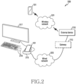
- FIG. 2 is a structural diagram of a system 200 according to various embodiments.
- the system 200 includes an electronic device 101, an external device 210, an external docking device 215, an external output device 217 and an external input device 219.
- the electronic device 101 communicates with the external device 210 through a wireless network 221 (e.g., short-range wireless communication), or through a wired network 223 (e.g., a wired local area network (LAN)).
- a wireless network 221 e.g., short-range wireless communication
- a wired network 223 e.g., a wired local area network (LAN)
- the electronic device 101 supports a desktop extension (DeX) mode. And it is connected to the network 223 through the docking device 215 in the desktop extension mode.
- the electronic device 101 includes a housing.
- the communication module 190 is disposed inside the housing.
- the display device 160 is exposed through the first portion of the housing, and the connector is exposed through the second portion of the housing.
- the electronic device 101 is inserted into the docking device 215 and is electrically connected to the docking device 215 via an electrical connector of a connection
- the electronic device 101 is electrically connected to the external output device 217 and the external input device 219 through the docking device 215 in the desktop extended mode.
- the electronic device 101 serves as a main body of the personal computer, and the external output device 217 serves as an output part of the personal computer, and the external input device 219 serves as an input part of the personal computer.
- the electronic device 101 displays a user interface similar to windows TM OS on the external output apparatus 217.
- the electronic device 101 fits the user interface (UI) or environment information related to the user interface (e.g., information about resolution, density, or orientation etc) in the desktop extended mode to the external output device 217.
- the electronic device 101 receives a user input through the external input device 219 in the desktop extended mode.
- the external device 210 provides a service to the electronic device 101 through the wired network 223.
- the external device 210 is a mobile device management (MDM) server.
- the external device 210 transmits a policy in association with an MDM client installed in the electronic device 101 to provide a service, and manages the electronic device 101 based on the policy.
- the external device 210 is connected to the docking device 215 through the wired network 223.
- the external device 210 is directly connected to the docking device 215.
- the external device 210 is connected to the docking device 215 through a gateway 213. Through this, the external device 210 communicates with the electronic device 101 through the wired network 223.
- the docking device 215 connects the electronic device 101 to the external device 210 through the wired network 223. As the docking device 215 is connected to the wired network 213 using a cable and the electronic device 101 is inserted into the docking device 215, the electronic device 101 is connected to the external device 210. In addition, the docking device 215 connects the electronic device 101 to the external output device 217 and the external input device 219. For example, the docking device 215 connects, in a wireless way or a wired way, the electronic device 101 to the external output device 217 and the external input device 219.
- the external output device 217 outputs at least one of video data or audio data.
- the external output device 217 outputs at least one of video data or audio data received from the electronic device 101 through the docking device 215.
- the external output device 217 includes at least one of a display, a speaker, a headset, or an earphone.
- the external input device 219 receives user input.
- the external input device 219 is, in a wireless way or a wired way, connected to the electronic device 101.
- the external input device 219 is, in a wireless way or a wired way, connected to the docking device 215.
- the external input device 219 includes at least one of a mouse, a keyboard, a joystick, a microphone, or a remote controller.
- Fig. 3 is a block diagram 300 illustrating the program 140 according to various embodiments.
- the program 140 may include an operating system (OS) 142 to control one or more resources of the electronic device 101, middleware 144, or an application 146 executable in the OS 142.
- the OS 142 may include, for example, AndroidTM, iOSTM, WindowsTM, SymbianTM, TizenTM, or BadaTM. At least part of the program 140, for example, may be pre-loaded on the electronic device 101 during manufacture, or may be downloaded from or updated by an external electronic device (e.g., the electronic device 102 or 104, or the server 108) during use by a user.
- an external electronic device e.g., the electronic device 102 or 104, or the server 108
- the OS 142 may control management (e.g., allocating or deallocation) of one or more system resources (e.g., process, memory, or power source) of the electronic device 101.
- the OS 142 additionally or alternatively, may include one or more driver programs to drive other hardware devices of the electronic device 101, for example, the input device 150, the sound output device 155, the display device 160, the audio module 170, the sensor module 176, the interface 177, the haptic module 179, the camera module 180, the power management module 188, the battery 189, the communication module 190, the subscriber identification module 196, or the antenna module 197.
- the middleware 144 may provide various functions to the application 146 such that a function or information provided from one or more resources of the electronic device 101 may be used by the application 146.
- the middleware 144 may include, for example, an application manager 301, a window manager 303, a multimedia manager 305, a resource manager 307, a power manager 309, a database manager 311, a package manager 313, a connectivity manager 315, a notification manager 317, a location manager 319, a graphic manager 321, a security manager 323, a telephony manager 325, or a voice recognition manager 327.
- the application manager 301 may manage the life cycle of the application 146.
- the window manager 303 may manage one or more graphical user interface (GUI) resources that are used on a screen.
- the multimedia manager 305 may identify one or more formats to be used to play media files, and may encode or decode a corresponding one of the media files using a codec appropriate for a corresponding format selected from the one or more formats.
- the resource manager 307 may manage the source code of the application 146 or a memory space of the memory 130.
- the power manager 309 may manage the capacity, temperature, or power of the battery 189, and determine or provide related information to be used for the operation of the electronic device 101 based at least in part on corresponding information of the capacity, temperature, or power of the battery 189.
- the power manager 309 may interwork with a basic input/output system (BIOS) (not shown) of the electronic device 101.
- BIOS basic input/output system
- the database manager 311, for example, may generate, search, or change a database to be used by the application 146.
- the package manager 313, for example, may manage installation or update of an application that is distributed in the form of a package file.
- the connectivity manager 315 for example, may manage a wireless connection or a direct connection between the electronic device 101 and the external electronic device.
- the notification manager 317 for example, may provide a function to notify a user of an occurrence of a specified event (e.g., an incoming call, message, or alert).
- the location manager 319 for example, may manage locational information on the electronic device 101.
- the graphic manager 321, for example, may manage one or more graphic effects to be offered to a user or a user interface related to the one or more graphic effects.
- the security manager 323, for example, may provide system security or user authentication.
- the telephony manager 325 for example, may manage a voice call function or a video call function provided by the electronic device 101.
- the voice recognition manager 327 may transmit a user's voice data to the server 108, and receive, from the server 108, a command corresponding to a function to be executed on the electronic device 101 based at least in part on the voice data, or text data converted based at least in part on the voice data.
- the middleware 344 may dynamically delete some existing components or add new components.
- at least part of the middleware 144 may be included as part of the OS 142 or may be implemented as another software separate from the OS 142.
- the DeX manager 329 manages the desktop extension mode. For example, the DeX manager 429 applies or restores settings that are applied to components of the electronic device 101 as the desktop extension mode is executed.
- the DeX UI manager 331 manages user interface resources associated with the desktop extension mode.
- the application 146 may include, for example, a home 351, dialer 353, short message service (SMS)/multimedia messaging service (MMS) 355, instant message (IM) 357, browser 359, camera 361, alarm 363, contact 365, voice recognition 367, email 369, calendar 371, media player 373, album 375, watch 377, health 379 (e.g., for measuring the degree of workout or biometric information, such as blood sugar), or environmental information 381 (e.g., for measuring air pressure, humidity, or temperature information) application.
- the application 146 may further include an information exchanging application (not shown) that is capable of supporting information exchange between the electronic device 101 and the external electronic device.
- the information exchange application may include a notification relay application adapted to transfer designated information (e.g., a call, message, or alert) to the external electronic device or a device management application adapted to manage the external electronic device.
- the notification relay application may transfer notification information corresponding to an occurrence of a specified event (e.g., receipt of an email) at another application (e.g., the email application 369) of the electronic device 101 to the external electronic device. Additionally or alternatively, the notification relay application may receive notification information from the external electronic device and provide the notification information to a user of the electronic device 101.
- the device management application may control the power (e.g., turn-on or turn-off) or the function (e.g., adjustment of brightness, resolution, or focus) of the external electronic device or some component thereof (e.g., a display device or a camera module of the external electronic device).
- the device management application additionally or alternatively, may support installation, delete, or update of an application running on the external electronic device.
- the DeX home 483 application operates as a launcher running in the desktop extended mode.
- the DeX home 483 application supports at least one of functions related to icons associated with the desktop extension mode such as creation, deletion, movement, association, or selection.
- the DeX UI 485 application provides a user interface associated with the desktop extension mode.
- the user interface associated with the desktop extension mode includes at least one of a notification, a presentation, a dialog, or a touch pad.
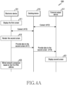
- FIG. 4A is a signal flow diagram of an electronic device 101, a docking device 215, and an external output device 217 in the system 200 according to various embodiments.
- the electronic device 101 displays the first screen in operation 411.
- the first screen includes a plurality of icons representing a plurality of application programs.
- the processor 120 displays the first screen in the first format. If the electronic device 101 is not connected to the external output device 217 through the docking device 215, the processor 120 displays the first screen through the display device 160.
- the electronic device 101 is electrically connected to the docking device 215 in operation 413. As the electronic device 101 is inserted into the docking device 215, it is connected to the docking device 215 through a connector. The docking device 215 is connected to the external output device 217 in operation 412. The docking device 215 is connected to the external output device 217 in a wireless way or a wired way. Through this, the electronic device 101 is connected to the external output device 217 through the docking device 215 in operation 513.
- the processor 120 is connected to the external output device 217 through the connector.
- the electronic device 101 When the electronic device 101 is connected to the docking device 215 in operation 413, the electronic device 101 renders the second screen in operation 415.
- the processor 120 renders the second screen in the second format.
- the second screen includes a plurality of icons representing a plurality of application programs.
- the electronic device 101 provides data associated with the second screen to the docking device 215 in operation 417.
- the processor 120 provides data associated with the second screen to the docking device 215 through the connector.
- the docking device 215 provides data related to the second screen to the external output device 217 in operation 419.
- the docking device 215 provides data associated with the second screen to the external output device 217 in a wireless way or a wired way. Through this, the external output device 217 displays the second screen in operation 421.
- the electronic device 101 is connected to the wired network 223 based on a first MAC address in operation 423. Accordingly, the electronic device 101 is connected to the external device 210 through the wired network 223.
- the processor 120 is connected to the wired network 223 through the docking device 215.
- the wired network 223 includes, for example, a wired LAN.
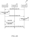
- FIG. 4B is a signal flow diagram of an electronic device 101, a docking device 215, and an external device 210 in the system 200 according to various embodiments.
- the electronic device 101 receives mobile device management (MDM) information from the external device 210 in operation 431.
- MDM mobile device management
- the processor 120 receives MDM information from the external device 210 through the communication module 190.
- the electronic device 101 receives MDM information for using of the wired network 323 through the wireless network 221.
- the electronic device 101 includes an MDM client, and the MDM client receives MDM information from the external device 210 based on a predetermined time, a location, or an event.
- the electronic device 101 generates a first MAC address in operation 433.
- the processor 120 generates the first MAC address in response to the MDM information.
- the processor 120 generates the first MAC address in response to MDM information.
- the electronic device 101 transmits the first MAC address to the external device 210 in operation 435.
- the processor 120 transmits the first MAC address to the external device 210 through the wireless network 221.
- the external device 210 reads the first MAC address from the electronic device 101.
- the processor 120 transmits user information of the electronic device 101 together with the first MAC address to the external device 210 through the communication module 190.
- the user information includes at least one of user name, contact information, or affiliation information.
- the external device 210 registers the first MAC address in operation 437.
- the external device 210 registers the first MAC address in response to user information.
- the external device 210 sets authority for using the wired network 223 of the electronic device 101 based on the user information. For example, the external device 210 allows or blocks the use of the wired network 223 for the electronic device 101, and determines the use range of the wired network 223 for the electronic device 101.
- the external device 210 registers the authority of the electronic device 101 corresponding to the first MAC address. According to an embodiment, the external device 210 transmits at least one of the first MAC address, user information, or authority to a gateway 213 and shares with the gateway 213.
- the electronic device 101 is electrically connected to the docking device 215 in operation 439. As the electronic device 101 is inserted into the docking device 215, it is connected to the docking device 215 through a connector.
- the electronic device 101 is connected to the external device 210 through the wired network 223 based on the first MAC address in operation 441.
- the processor 120 is connected to the wired network 223 through the docking device 215.
- the wired network 223 includes, for example, a wired LAN.
- the electronic device 101 receives a second MAC address from the docking device 215 in operation 440. Through this, the electronic device 101 is connected to the wired network 223 using the first MAC address in response to the second MAC address in operation 441.
- the second MAC address is stored in the docking device 215, and the docking device 215 uses it to connect to the wired LAN and, for example, includes the second MAC address.
- the processor 120 is connected to the wired network 223 through the docking device 215.
- the electronic device 101 causes the docking device 215 to use the first MAC address for connection to a wired LAN.
- the processor 120 uses the wired network 223 based on the first MAC address.
- the electronic device 101 includes a housing, a display exposed through a first portion of the housing, a wireless communication circuit disposed inside the housing, and an electrical connector exposed through a second portion of the housing, a display, and a processor 120 electrically connected to the communication circuit and the connector, and a memory 130 electrically connected to the processor 120.
- the memory 130 stores the instructions, when executed, cause the processor 120, in the first operation, to display a first screen including a plurality of icons representing a plurality of application programs on a display in a first format if the electronic device 101 is not connected to the external output device 217, and in a second operation, while the external docking device 215 is connected to the wired local area network (LAN) when the electronic device is inserted into the external docking device using a connector and connected to the external output device through the external docking device, to render a second screen including the plurality of icons of the first screen in a second format, to provide data related to the second screen to the external output device through the connector for the external output device to display the second screen, and to connect the electronic device to the wired LAN through the connector using a first media access control (MAC) address shared with an external device on the wired LAN
- MAC media access control
- the connector includes a universal serial bus (USB) connector.
- USB universal serial bus
- the instructions further cause the processor 120 to receive mobile device management (MDM) information from the external device 210 and generate the first MAC address in response to the MDM information.
- MDM mobile device management
- the instructions further cause the processor 120 to generate the first MAC address using the WiFi MAC address.
- the instructions cause the processor 120 to process the WiFi MAC address using a bit masking algorithm to generate the first MAC address.
- the instructions cause the processor 120, in the second operation, to receive the second MAC address stored in the docking device 215 from the docking device 215 and, after receiving the second MAC address, to let the docking device 215 to use the first MAC address to connect to the wired LAN.
- the instructions cause the processor 120, in the second operation, to provide the docking device 215 with a request for the second MAC address, and after providing the request, to receive a second MAC address from the docking device 215.
- the instructions cause the processor 120, in the second operation, to display a user interface (UI) including at least a portion of the first MAC address on the display.
- UI user interface
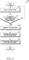
- FIG. 5 is a flowchart of an operation method 500 of an electronic device 101 according to various embodiments.
- the electronic device 101 displays the first screen in operation 511.
- the first screen includes a plurality of icons representing a plurality of application programs.
- the processor 120 displays the first screen in the first format.
- the electronic device 101 determines whether the electronic device 101 is connected to the external output device through the docking device 215. If the electronic device 101 is not connected to the external output device 217 through the docking device 215, the electronic device 101 continues to display the first screen.
- the electronic device 101 When the electronic device 101 is connected to the external output device 217 through the docking device 215 in operation 513, the electronic device 101 renders the second screen in operation 515.
- the electronic device 101 is inserted into the docking device 215 and connected to the external output device 217 through the docking device 215.
- the processor 120 renders the second screen in the second format.
- the second screen includes a plurality of icons representing a plurality of application programs.
- the electronic device 101 provides data associated with the second screen to the docking device 215 in operation 517.
- the processor 120 provides data associated with the second screen to the docking device 215 through a connector.
- the processor 120 provides data associated to the second screen to the external output device 217 through the docking device 215.
- the electronic device 101 is connected to the wired network 223 based on the first MAC address in operation 519. While the docking device 215 is connected to the wired network 223, the processor 120 is connected to the wired network 223 through the docking device 215 based on the first MAC address. The processor 120 is connected to the external device 210 through the wired network 223.
- the wired network 223 includes, for example, a wired LAN.
- FIG. 6 is a flowchart of an operation method 600 of an electronic device 101 according to various embodiments.
- the processor 120 determines whether the electronic device is connected to the docking device. If the electronic device 101 is not connected to the docking device 215, the electronic device 101 performs the first operation in operation 613. When the electronic device 101 is not inserted into the docking device 215, the processor 120 performs the first operation. If the electronic device 101 is not connected to the external output device 217 and the external input device 219 through the docking device 215, the processor 120 perform the first operation.
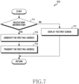
- FIG. 7 is a flowchart of the first operation 613 of FIG. 6 .
- operations of FIG. 7 are at least some of operation 613 of FIG. 6 .
- FIG. 8 is an exemplary data structure of the first MAC address of FIG. 7 .
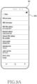
- FIG. 9A and FIG. 9B are exemplary views of the first screen 910 of FIG. 7 .
- the electronic device 101 determines whether MDM information is received in operation 711.
- the electronic device 101 receives MDM information.
- the processor 120 receives MDM information from the external device 210 through the communication module 190.
- the electronic device 101 receives MDM information through the wireless network 221.
- the electronic device 101 includes an MDM client, and the MDM client receives MDM information from the external device 210 based on a predetermined time, a location, or an event.
- the electronic device 101 When MDM information is received, the electronic device 101 generates a first MAC address in operation 713.
- the processor 120 generates the first MAC address in response to receiving the MDM information.
- the processor 120 generates the first MAC address in response to receiving the MDM information.
- the processor 120 generates the first MAC address using a pre-stored MAC address for use in connecting to the wireless network 221, and stores the first MAC address.
- the pre-stored MAC address includes a BT MAC address or a WiFi MAC address, or both of the BT MAC address and the WiFi MAC address.
- the processor 120 generates the first MAC address using the BT MAC address.
- the processor 120 generates the first MAC address using the WiFi MAC address.
- the processor 120 processes the WiFi MAC address with bit masking algorithm and generates the first MAC address.
- the WiFi MAC address and the first MAC address have the same data structure as shown in FIG. 8 .
- the WiFi MAC address and the first MAC address are formed of a row of six octets. Each octet is formed of a row of eight bits.
- the processor 120 generates the first MAC address by changing the second and fifth octets in the WiFi MAC address.
- the processor 120 applies 0x02 and OR functions to the fifth bit, the sixth bit, the seventh bit and the eighth bit of the second octets in the WiFi MAC address, and applies 0x40 and XOR functions to the first bit, the second bit, the third bit and the fourth bit of the fifth octets in the WiFi MAC address.
- the processor 120 applies the 0x02 and OR functions to 'C (1100)' of the second octet to produce 'E (1110)' and applies the 0x40 and XOR functions to '3 (0011)' of the fifth octet to produce '7 (0111)'.
- the processor 120 generates '8E: F5: A 3: 63: 79: FC' as the first MAC address.
- the electronic device 101 transmits the first MAC address to the external device 210 in operation 715.
- the processor 120 transmits the first MAC address to the external device 210 through the wireless network 221.
- the processor 120 receives a request for the first MAC address from the external device 210 through the communication module 190. Through this, the processor 120 transmits the first MAC address to the external device 210 through the communication module 190 in response to the request from the external device 210.
- the processor 120 transmits user information of the electronic device 101 to the external device 210 together with the first MAC address.
- the user information includes at least one of a user name, contact information, or affiliation information.
- the processor 120 further transmits not only the user information of the electronic device 101, but also identification information of the electronic device 101 such as an international mobile equipment identity (IMEI) or an international mobile subscriber identity (IMSI).
- IMEI international mobile equipment identity
- IMSI international mobile subscriber identity
- the electronic device 101 displays the first screen 910 in operation 717.
- the first screen 910 includes a plurality of icons representing a plurality of application programs.
- the processor 120 displays the first screen 910 in the first format.
- the processor 120 displays the first screen 910 through the display device 160 as illustrated in FIG. 9A .
- the processor 120 displays the user interface 920 including at least a portion of a MAC address pre-stored through the display device 160 as illustrated in FIG. 9B .
- the user interface 920 includes at least a portion of the pre-stored MAC address, but does not include the first MAC address.
- the processor 120 displays, through the user interface 920, the WiFi MAC address, for example, '8C: F5: A3: 63: 79: F7' but does not display the first MAC address, for example, '8E: F5: A3: 63: 79: FC'.
- the electronic device 101 When the electronic device 101 is connected to the docking device 215 in operation 611, the electronic device 101 performs the second operation in operation 615.
- the processor 120 When the electronic device 101 is inserted into the docking device 215, the processor 120 performs the second operation.
- the processor 120 When the electronic device 101 is connected to the external output device 217 and the external input device 219 through the docking device 215, the processor 120 performs the second operation. In the second operation, the processor 120 operates in the desktop extended mode.
- the electronic device 101 renders the second screen 1110 in operation 1011.
- the processor 120 renders the second screen 1110 in a second format.
- the second screen 1110 includes a plurality of icons representing a plurality of application programs.
- the electronic device 101 provides data associated with the second screen 1110 to the docking device 215.
- the processor 120 provides data associated with the second screen 1110 to the docking device 215 through a connector.
- the processor 120 provides data associated with the second screen 1110 to the external output device 217 through the docking device 215. Through this, the processor 120 displays the second screen 1110 through the external output device 217 as shown in FIG. 11A .
- the electronic device 101 provide a request for the second MAC address to the docking device 215 in operation 1015.
- the second MAC address is stored in the docking device 215 for use by the docking device 215 to connect to a wired LAN.
- the electronic device 101 receives the second MAC address from the docking device 215 in operation 1017.
- the electronic device 101 determines whether the first MAC address exists.
- the processor 120 determines whether the first MAC address is stored separately from the previously stored MAC address.
- the electronic device 101 If it is determined in operation 1019 that the first MAC address exists, the electronic device 101 requests to use the wired network 223 based on the first MAC address in operation 1021. In operation 1021, the electronic device 101 requests to use the wired network 223 based on the first MAC address.
- the processor 120 displays the user interface 1120 including at least a portion of the first MAC address through the display device 160 as illustrated in FIG. 11B .
- the user interface 1120 includes at least a portion of the first MAC address along with at least a portion of the pre-stored MAC address.
- the processor 120 displays, through the user interface 1120, a WiFi MAC address such as '8C: F5: A3: 63: 79: F7' and a first MAC address such as '8E: F5: A3: 63: 79: FC'.
- the processor 120 requests the external device 210 to use the wired network 223 through the docking device 215.
- the processor 120 causes the docking device 215 to request the external device 210 to use the wired network 223 using the first MAC address.
- the electronic device 101 determines whether the use of the wired network 223 is permitted in operation 1023.
- the processor 120 determines whether the use of the wired network 223 is permitted from the external device 210 through the docking device 215. If the use of the wired network 223 is permitted in operation 1023, the electronic device 101 uses the wired network 223 based on the first MAC address in operation 1025.
- the processor 120 is connected to the wired network 223 through the docking device 215. For example, the electronic device 101 causes the docking device 215 to use the first MAC address for connection to a wired LAN. Through this, the processor 120 uses the wired LAN based on the first MAC address. If the use of the wired network 223 is not permitted and is blocked in operation 1023, the electronic device 101 does not use the wired network 223.
- the electronic device 101 requests the use of the wired network 223 based on the second MAC address in operation 1041.
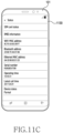
- the processor 120 displays the user interface 1130 including at least a portion of the second MAC address through the display device 160 as illustrated in FIG. 11C .
- the user interface 1130 includes at least a portion of the second MAC address along with at least a portion of the pre-stored MAC address.
- the processor 120 displays, through the user interface 1130, a WiFi MAC address such as '8C: F5: A 3: 63: 79: F7' and a second MAC address such as 'A6: C8: 90: 83: E1: 25'.
- the processor 120 requests the external device 210 to use the wired network 223 through the docking device 215.
- the processor 120 causes the docking device 215 to request the external device 210 to use the wired network 223 using the second MAC address.
- the electronic device 101 determines whether the use of the wired network 223 is permitted in operation 1043.
- the processor 120 determines whether the use of the wired network 223 is permitted from the external device 210 through the docking device 215. If the use of the wired network 223 is permitted in operation 1043, the electronic device 101 uses the wired network 223 based on the second MAC address in operation 1045.
- the processor 120 is connected to the wired network 223 through the docking device 215. For example, the electronic device 101 causes the docking device 215 to use the second MAC address for connection to a wired LAN. Through this, the processor 120 uses the wired LAN based on the second MAC address. If the use of the wired network 223 is not permitted and is blocked in operation 1043, the electronic device 101 cannot use the wired network 223.
- FIG. 12 is a flowchart of the second operation 615 of FIG. 6 .
- operations of FIG. 12 are at least some of operation 615 of FIG. 6 .
- the electronic device 101 renders the second screen 1110 in operation 1211.
- the processor 120 renders the second screen 1110 in a second format.
- the second screen 1110 includes a plurality of icons representing a plurality of application programs.
- the electronic device 101 provides data associated with the second screen 1110 to the docking device 215.
- the processor 120 provides data associated with the second screen 1110 to the docking device 215 through a connector.
- the processor 120 provides data associated with the second screen 1110 to the external output device 217 through the docking device 215. Through this, the processor 120 displays the second screen 1110 through the external output device 217 as shown in FIG. 11A .
- the electronic device 101 determines whether the first MAC address exists.
- the processor 120 determines whether the first MAC address is stored separately from the previously stored MAC address.
- the electronic device 101 requests for the use of the wired network 223 based on the first MAC address in operation 1221.
- the processor 120 displays the user interface 1120 including at least a portion of the first MAC address through the display device 160 as illustrated in FIG. 11B .
- the user interface 1120 includes at least a portion of the first MAC address along with at least a portion of the pre-stored MAC address.
- the processor 120 displays, through the user interface 1120, a WiFi MAC address such as '8C: F5: A 3: 63: 79: F7' and a first MAC address such as '8E: F5: A3: 63: 79: FC'.
- the processor 120 requests, through the docking device 215, the external device 210 to use the wired network 223.
- the processor 120 causes the docking device 215 to request the external device 210 to use the wired network 223 using the first MAC address.
- the electronic device 101 if it is determined in operation 1215 that the first MAC address exists, the electronic device 101 requests the second MAC address from the docking device 215 in operation 1217.
- the second MAC address is stored in the docking device 215 for use by the docking device 215 to connect to the wired LAN, and includes, for example, a second MAC address.
- the electronic device 101 receives the second MAC address from the docking device 215 in operation 1219. After receiving the second MAC address from the docking device 215, the electronic device 101 requests to use the wired network 223 based on the first MAC address in operation 1221.
- the electronic device 101 receives the second MAC address from the docking device 215 in operation 1219. That is, the processor 120 performs operation 1219 without performing operation 1217. After receiving the second MAC address from the docking device 215, the electronic device 101 requests to use the wired network 223 based on the first MAC address in operation 1221.
- the electronic device 101 requests to use the wired network 1223 based on the first MAC address in operation 1221. That is, the processor 120 performs operation 1221 without performing operations 1217 and 1219.
- the electronic device 101 determines whether the use of the wired network 223 is permitted.
- the processor 120 determines, through the docking device 215, whether the use of the wired network 223 is permitted from the external device 210. If the use of the wired network 223 is permitted in operation 1223, the electronic device 101 uses the wired network 223 based on the first MAC address in operation 1225.
- the processor 120 is connected to the wired network 223 through the docking device 215. For example, the electronic device 101 causes the docking device 215 to use the first MAC address for connection to a wired LAN. Through this, the processor 120 uses a wired LAN based on the first MAC address. If the use of the wired network 223 is not allowed and is blocked in operation 1223, the electronic device 101 does not use the wired network 223.
- the electronic device 101 If it is determined in operation 1215 that the first MAC address does not exist, the electronic device 101 requests the second MAC address from the docking device 215 in operation 1237.
- the second MAC address is stored in the docking device 215 for use by the docking device 215 to connect to the wired LAN, and includes, for example, a second MAC address.
- the electronic device 101 receives the second MAC address from the docking device 215 in operation 1239.
- the electronic device 101 After receiving the second MAC address from the docking device 215 in operation 1239, the electronic device 101 requests to use the wired network 223 based on the second MAC address in operation 1241.
- the processor 120 displays the user interface 1130 including at least a portion of the second MAC address through the display device 160 as illustrated in FIG. 11C .
- the user interface 1130 includes at least a portion of the second MAC address along with at least a portion of the pre-stored MAC address.
- the processor 120 displays, through the user interface 1130, the WiFi MAC address such as '8C: F5: A 3: 63: 79: F7' and the second MAC address such as 'A6: C8: 90: 83: E1: 25'.
- the processor 120 requests the external device 210 to use the wired network 223 through the docking device 215.
- the processor 120 causes the docking device 215 to request the external device 210 to use the wired network 223 using the second MAC address.
- the electronic device 101 determines whether the use of the wired network 223 is permitted in operation 1243.
- the processor 120 determines whether the use of the wired network 223 is permitted from the external device 210 through the docking device 215. If the use of the wired network 223 is permitted in operation 1243, the electronic device 101 uses the wired network 223 based on the second MAC address in operation 1245.
- the processor 120 is connected to the wired network 223 through the docking device 215. For example, the electronic device 101 causes the docking device 215 to use a second MAC address for connection to a wired LAN. Through this, the processor 120 uses a wired LAN based on the second MAC address. If the use of the wired network 223 is not allowed and is blocked in operation 1243, the electronic device 101 does not use the wired network 223.
- FIG. 13 is a flowchart of an operation method 1300 of an external device 210 according to an embodiment.
- the external device 210 transmits MDM information in operation 1311.
- the external device 210 periodically transmits MDM information.
- the external device 210 transmits MDM information for use of the wired network 223 through the wireless network 221.
- the external device 210 transmits MDM information to the MDM client of the electronic device 101 based on a predetermined time, a location, or an event.
- the external device 210 receives the first MAC address from the electronic device 101 in operation 1313.
- the external device 210 receives the first MAC address of the electronic device 101 through the wireless network 221.
- the external device 210 reads the first MAC address from the electronic device 101.
- the external device 210 receives user information of the electronic device 101 together with the first MAC address.
- the user information includes at least one of user name, contact information, or affiliation information.
- the external device 210 registers the first MAC address in response to user information.
- the external device 210 sets authority for use of the wired network 223 of the electronic device 101.
- the external device 210 sets authority for use of the wired network 223 of the electronic device 101 based on the user information. For example, the external device 210 allows or blocks the use of the wired network 223 for the electronic device 101, and determines the use range of the wired network 223 for the electronic device 101.
- the external device 210 registers the authority of the electronic device 101 corresponding to the first MAC address.
- the external device 210 receives a request to use the wired network 223 based on the first MAC address.
- the external device 210 receives a request to use the wired network 223 from the electronic device 101 based on the first MAC address through the docking device 215.
- the external device 210 determines whether to allow the use of the wired network 223 based on the first MAC address in operation 1319.
- the external device 210 identifies the authority of the electronic device 101 based on the first MAC address.
- the external device 210 determines whether the electronic device 101 is set to allow the use of the wired network 223.
- the external device 210 allows the use of the wired network 223 for the electronic device 101 in operation 1321.
- the external device 210 allows the use of the wired network 223 for the electronic device 101 through the docking device 215.
- the external device 210 communicates with the electronic device 101 through the wired network 223 in operation 1323.
- the external device 210 communicates with the electronic device 101 based on the first MAC address through the docking device 215.
- the external device 210 communicates with the electronic device 101 based on the scope of use of the wired network 223 in the authority of the electronic device 101.
- the external device 210 blocks the use of the wired network 223 for the electronic device 101 in operation 1325.
- the external device 210 does not communicate with the electronic device 101 through the wired network 223.
- FIG. 14 is a flowchart of an operation method 1400 of an external device 210 according to another embodiment.
- the external device 210 transmits MDM information in operation 1411.
- the external device 210 periodically transmits MDM information.
- the external device 210 transmits MDM information for use of the wired network 223 through the wireless network 221.
- the external device 210 transmits MDM information to the MDM client of the electronic device 101 based on a predetermined time, a location, or an event.
- the external device 210 receives the first MAC address from the electronic device 101 in operation 1413.
- the external device 210 receives the first MAC address of the electronic device 101 through the wireless network 221.
- the external device 210 reads the first MAC address from the electronic device 101.
- the first MAC address includes, for example, the first MAC address.
- the external device 210 receives user information of the electronic device 101 together with the first MAC address.
- the user information includes at least one of user name, contact information, or affiliation information.
- the external device 210 registers the first MAC address in response to user information.
- the external device 210 sets authority for using the wired network 223 of the electronic device 101.
- the external device 210 sets authority for using the wired network 223 of the electronic device 101 based on the user information. For example, the external device 210 allows or blocks the use of the wired network 223 for the electronic device 101, and determines the use range of the wired network 223 for the electronic device 101.
- the external device 210 registers the authority of the electronic device 101 corresponding to the first MAC address.
- the external device 210 communicates with the gateway 213 in operation 1417.
- the external device 210 transmits the first MAC address and authority of the electronic device 101 to the gateway 213.
- the external device 210 further transmits the user information along with the first MAC address and authority of the electronic device 101 to the gateway 213. Thereafter, if the electronic device 101 is allowed to use the wired network 223, the external device 210 communicates with the electronic device 101 through the gateway 213.
- the external device 210 communicates with the electronic device 101 based on the first MAC address through the docking device 215.
- the external device 210 communicates with the electronic device 101 based on the scope of use of the wired network 223 in the authority of the electronic device 101.
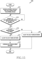
- FIG. 15 is a flowchart of an operation method 1500 of a gateway 213 according to another embodiment.
- the gateway 213 receives authority for each first MAC address from the external device 210 in operation 1511.
- the gateway 213 receives the first MAC address and authority of the electronic device 101 from the external device 210.
- the gateway 213 stores authority of the electronic device 101 corresponding to the first MAC address.
- the gateway 213 further receives user information along with the first MAC address and authority of the electronic device 101.
- the gateway 213 stores user information and authority of the electronic device 101 corresponding to the first MAC address.
- the gateway 213 receives a request to use the wired network 223 based on the first MAC address.
- the gateway 213 receives a request to use the wired network 223 from the electronic device 101 based on the first MAC address through the docking device 215.
- the gateway 213 determines whether to allow the use of the wired network 223 based on the first MAC address in operation 1515.
- the gateway 213 identifies the authority of the electronic device 101 based on the first MAC address.
- the gateway 213 determines whether the electronic device 101 is set to allow the use of the wired network 223.
- the gateway 213 allows the use of the wired network 223 for the electronic device 101 in operation 1517.
- the gateway 213 allows the use of the wired network 223 for the electronic device 101 through the docking device 215.
- the gateway 213 communicates with the electronic device 101 through the wired network 223.
- the gateway 213 communicates with the electronic device 101 based on the first MAC address through the docking device 215. Through this, the gateway 213 relays communication between the electronic device 101 and the external device 210.
- the gateway 213 blocks the use of the wired network 223 for the electronic device 101 in operation 1521.
- the gateway 213 does not communicate with the electronic device 101 through the wired network 223.
- Operation method of the electronic device 101 includes a first operation performed when the electronic device 101 is not connected to the external output device 217 and a second operation performed while the docking device 215 is connected to the wired LAN when the electronic device 101 is inserted into the docking device 215 using a connector and connected to the external output device 217 through the docking device 215.
- the first operation includes an operation of displaying a first screen including a plurality of icons representing a plurality of application programs in a first format.
- the second operation includes rendering a second screen including a plurality of icons in a second format, providing the data associated with the second screen to the external output device 217 through the connector so that the external output device 217 displays the second screen, and connecting the electronic device 101 to the wired LAN through the connector using the first MAC address shared with the external device 210 on the wired LAN.
- the connector includes a universal serial bus (USB) connector.
- USB universal serial bus
- the method further includes receiving mobile device management (MDM) information from the external device 210 and generating a first MAC address in response to the MDM information.
- MDM mobile device management
- the method of the electronic device 101 further includes generating a first MAC address using the WiFi MAC address.
- generating the first MAC address includes generating the first MAC address by processing the WiFi MAC address with bit masking algorithm.
- the second operation further includes receiving the second MAC address stored in the docking device 215 from the docking device 215 and after receiving the second MAC address, causing the docking device 215 to use the first MAC address to connect to the wired LAN.
- the second operation further includes providing a request for the second MAC address to the docking device 215 and receiving the second MAC address from the docking device 215 after providing the request.
- the second operation further includes displaying a user interface (UI) including at least a portion of the first MAC address.
- UI user interface
- Non-transitory computer-readable storage medium stores one or more programs for performing the first operation performed based on that the electronic device 101 is not connected to the external output device 217, and a second operation performed when the electronic device 101 is inserted into the external docking device 215 using the connector and connected to the external output device 217 through the docking device 215.
- the first operation includes an operation of displaying a first screen including a plurality of icons representing a plurality of application programs in a first format.
- the second operation includes rendering a second screen including a plurality of icons in a second format, providing the data associated with the second screen to 217 to the external output device through the connector so that the external output device 217 displays the second screen, and connecting the electronic device 101 to the wired LAN through the connector using the first MAC address shared with the external device 210 on the wired LAN.
- the program further executes an operation of receiving mobile device management (MDM) information from the external device 210 and an operation of generating a first MAC address in response to the MDM information.
- MDM mobile device management
- the program further performs an operation of generating a first MAC address using a WiFi MAC address.
- generating the first MAC address includes generating a first MAC address by processing WiFi MAC address with bit masking algorithm.
- the electronic device 101 generates a unique MAC address and use it to connect to the wired network 223. Through this, even if the electronic device 101 is inserted into the docking device 215, the electronic device 01 uses the wired network 223 based on the unique MAC address. Accordingly, since the external device 210 is able to identify the electronic device 101, the external device 210 allows or blocks the use of the wired network 223 for the electronic device 101, and sets the range of use of the wired network 223 for the electronic device 101.
- the electronic device may be one of various types of electronic devices.
- the electronic devices may include, for example, a portable communication device (e.g., a smart phone), a computer device, a portable multimedia device, a portable medical device, a camera, a wearable device, or a home appliance. According to an embodiment of the disclosure, the electronic devices are not limited to those described above.
- each of such phrases as “A or B,” “at least one of A and B,” “at least one of A or B,” “A, B, or C,” “at least one of A, B, and C,” and “at least one of A, B, or C,” may include all possible combinations of the items enumerated together in a corresponding one of the phrases.
- such terms as “1st” and “2nd,” or “first” and “second” may be used to simply distinguish a corresponding component from another, and does not limit the components in other aspect (e.g., importance or order).
- an element e.g., a first element
- the element may be coupled with the other element directly (e.g., wiredly), wirelessly, or via a third element.
- module may include a unit implemented in hardware, software, or firmware, and may interchangeably be used with other terms, for example, “logic,” “logic block,” “part,” or “circuitry”.
- a module may be a single integral component, or a minimum unit or part thereof, adapted to perform one or more functions.
- the module may be implemented in a form of an application-specific integrated circuit (ASIC).
- ASIC application-specific integrated circuit
- Various embodiments as set forth herein may be implemented as software (e.g., the program 140) including one or more instructions that are stored in a storage medium (e.g., internal memory 136 or external memory 138) that is readable by a machine (e.g., the electronic device 101) .
- a processor e.g., the processor 120
- the machine e.g., the electronic device 101
- the one or more instructions may include a code generated by a complier or a code executable by an interpreter.
- the machine-readable storage medium may be provided in the form of a non-transitory storage medium.
- non-transitory simply means that the storage medium is a tangible device, and does not include a signal (e.g., an electromagnetic wave), but this term does not differentiate between where data is semi-permanently stored in the storage medium and where the data is temporarily stored in the storage medium.
- a method may be included and provided in a computer program product.
- the computer program product may be traded as a product between a seller and a buyer.
- the computer program product may be distributed in the form of a machine-readable storage medium (e.g., compact disc read only memory (CD-ROM)), or be distributed (e.g., downloaded or uploaded) online via an application store (e.g., Play StoreTM), or between two user devices (e.g., smart phones) directly. If distributed online, at least part of the computer program product may be temporarily generated or at least temporarily stored in the machine-readable storage medium, such as memory of the manufacturer's server, a server of the application store, or a relay server.
- CD-ROM compact disc read only memory
- an application store e.g., Play StoreTM
- two user devices e.g., smart phones
- each component e.g., a module or a program of the above-described components may include a single entity or multiple entities. According to various embodiments, one or more of the above-described components may be omitted, or one or more other components may be added. Alternatively or additionally, a plurality of components (e.g., modules or programs) may be integrated into a single component. In such a case, according to various embodiments, the integrated component may still perform one or more functions of each of the plurality of components in the same or similar manner as they are performed by a corresponding one of the plurality of components before the integration.
- operations performed by the module, the program, or another component may be carried out sequentially, in parallel, repeatedly, or heuristically, or one or more of the operations may be executed in a different order or omitted, or one or more other operations may be added.
Landscapes
- Engineering & Computer Science (AREA)
- Theoretical Computer Science (AREA)
- General Engineering & Computer Science (AREA)
- Physics & Mathematics (AREA)
- General Physics & Mathematics (AREA)
- Human Computer Interaction (AREA)
- Software Systems (AREA)
- Computer Networks & Wireless Communication (AREA)
- Signal Processing (AREA)
- Telephone Function (AREA)
Description
- Various embodiments relate to an electronic device for using a wired network through a docking device and a method of operating the electronic device.
- With the development of mobile communication technology, an electronic device performs various data communication functions as well as voice call functions. The electronic device provides various services through various applications. The electronic device provides a multimedia service, for example, a music service, a video service, or a digital broadcast service, or a call, wireless Internet, short message service (SMS), multimedia messaging service (MMS), and the like which are network-based communication services. And, as the electronic device evolves from a simple communication medium to a device capable of various functions such as communication, distribution, the Internet, or payment, it has been used throughout the social, cultural, financial, or distribution industries.
- As the electronic device is inserted into a docking device, it operates in a usage environment similar to that of a general personal computer. That is, the electronic device uses a wired network through a docking device. For example, the electronic device uses a service provided by an external device through the wired network.
US 2015/0138094 A1 discloses an electronic apparatus includes a communication interface configured to, when a docking apparatus including a keyboard and a display is connected, perform communication with the docking apparatus, a user interface configured to receive a user control command using a touch screen, and a controller configured to display image data on at least one of the display of the docking apparatus and the touch screen according to the input control command and whether the docking apparatus is mounted, and the electronic apparatus is disposed between the keyboard and the display.
US 2017/0344333 A1 discloses an electronic device includes a memory configured to store an application including a plurality of resources, each of the resources is matched to each of a plurality of characteristic information which include a first characteristic information of the electronic device and a second characteristic information of an external electronic device.
US 2017/0344507 A1 relates to a method for managing a docking device and the docking device thereof. The docking device is configured with a processor and at least two coupling ports. - However, the electronic device as described above uses a wired network based on a media access control (MAC) address of the docking device. Due to this, there is a problem that the external device only identifies the docking device, and the electronic device is not identified. Accordingly, the external device is not able to allow or block the use of the wired network of the electronic device.
- Embodiments provide an electronic device for using a wired network through a docking device and a method of operating the electronic device, as set out in appended set of claims.
- According to various embodiments, an electronic device generates a unique MAC address and use it to connect to a wired network. Through this, even if the electronic device is inserted into the docking device, the electronic device is able to use a wired network based on the unique MAC address. Accordingly, since the external device is able to identify the electronic device, the use range of the network is controlled by allowing or blocking the use of the wired network for the electronic device.
-
-
FIG. 1 is a block diagram of an electronic device in a network environment according to an example not including all the claimed features. -
FIG. 2 is a structural diagram of a system according to an example not including all the claimed features. -
FIG. 3 is a block diagram illustrating a program according to an example not including all the claimed features. -
FIG. 4A is a signal flow diagram in a system according to an example not including all the claimed features. -
FIG. 4B is a signal flow diagram in a system according to an example not including all the claimed features. -
FIG. 5 is a flowchart of a method of operating an electronic device according to an example not including all the claimed features. -
FIG. 6 is a flowchart of an operation method of an electronic device according to various embodiments. -
FIG. 7 is a flowchart of the first operation ofFIG. 6 . -
FIG. 8 is an exemplary data structure of the first MAC address inFIG. 7 . -
FIG. 9A andFIG. 9B are exemplary views of the first screen ofFIG. 7 . -
FIG. 10 is a flowchart of the second operation ofFIG. 6 . -
FIG. 11A ,FIG. 11B , andFIG. 11C are exemplary views of the second screen ofFIG. 10 . -
FIG.12 is a flowchart of the second operation ofFIG.6 . -
FIG.13 is a flowchart of a method of operating an external device according to an example not including all the claimed features. -
FIG.14 is a flowchart of a method of operating an external device according to an example not including all the claimed features. -
FIG.15 is a flowchart of a method of operating a gateway according to an example not including all the claimed features. - Hereinafter, various embodiments of the document will be described with reference to the accompanying drawings.
-
Fig. 1 is a block diagram illustrating anelectronic device 101 in anetwork environment 100 according to various embodiments. - Referring to
Fig. 1 , theelectronic device 101 in thenetwork environment 100 may communicate with anelectronic device 102 via a first network 198 (e.g., a short-range wireless communication network), or anelectronic device 104 or aserver 108 via a second network 199 (e.g., a long-range wireless communication network). According to an embodiment, theelectronic device 101 may communicate with theelectronic device 104 via theserver 108. According to an embodiment, theelectronic device 101 may include aprocessor 120,memory 130, aninput device 150, asound output device 155, adisplay device 160, anaudio module 170, asensor module 176, aninterface 177, ahaptic module 179, acamera module 180, apower management module 188, abattery 189, acommunication module 190, a subscriber identification module (SIM) 196, or anantenna module 197. In some embodiments, at least one (e.g., thedisplay device 160 or the camera module 180) of the components may be omitted from theelectronic device 101, or one or more other components may be added in theelectronic device 101. In some embodiments, some of the components may be implemented as single integrated circuitry. For example, the sensor module 176 (e.g., a fingerprint sensor, an iris sensor, or an illuminance sensor) may be implemented as embedded in the display device 160 (e.g., a display). - The processor 120may execute, for example, software (e.g., a program 140) to control at least one other component (e.g., a hardware or software component) of the
electronic device 101 coupled with theprocessor 120, and may perform various data processing or computation. According to one embodiment, as at least part of the data processing or computation, theprocessor 120 may load a command or data received from another component (e.g., thesensor module 176 or the communication module 190) involatile memory 132, process the command or the data stored in thevolatile memory 132, and store resulting data innon-volatile memory 134. According to an embodiment, theprocessor 120 may include a main processor 121 (e.g., a central processing unit (CPU) or an application processor (AP)), and an auxiliary processor 123 (e.g., a graphics processing unit (GPU), an image signal processor (ISP), a sensor hub processor, or a communication processor (CP)) that is operable independently from, or in conjunction with, themain processor 121. Additionally or alternatively, theauxiliary processor 123 may be adapted to consume less power than themain processor 121, or to be specific to a specified function. Theauxiliary processor 123 may be implemented as separate from, or as part of themain processor 121. - The
auxiliary processor 123 may control at least some of functions or states related to at least one component (e.g., thedisplay device 160, thesensor module 176, or the communication module 190) among the components of theelectronic device 101, instead of themain processor 121 while themain processor 121 is in an inactive (e.g., sleep) state, or together with themain processor 121 while themain processor 121 is in an active state (e.g., executing an application). According to an embodiment, the auxiliary processor 123 (e.g., an image signal processor or a communication processor) may be implemented as part of another component (e.g., thecamera module 180 or the communication module 190) functionally related to theauxiliary processor 123. - The
memory 130 may store various data used by at least one component (e.g., theprocessor 120 or the sensor module 176) of theelectronic device 101. The various data may include, for example, software (e.g., the program 140) and input data or output data for a command related thereto. Thememory 130 may include thevolatile memory 132 or thenon-volatile memory 134. - The
program 140 may be stored in thememory 130 as software, and may include, for example, an operating system (OS) 142,middleware 144, or anapplication 146. - The
input device 150 may receive a command or data to be used by other component (e.g., the processor 120) of theelectronic device 101, from the outside (e.g., a user) of theelectronic device 101. Theinput device 150 may include, for example, a microphone, a mouse, or a keyboard. - The
sound output device 155 may output sound signals to the outside of theelectronic device 101. Thesound output device 155 may include, for example, a speaker or a receiver. The speaker may be used for general purposes, such as playing multimedia or playing record, and the receiver may be used for an incoming calls. According to an embodiment, the receiver may be implemented as separate from, or as part of the speaker. - The
display device 160 may visually provide information to the outside (e.g., a user) of theelectronic device 101. Thedisplay device 160 may include, for example, a display, a hologram device, or a projector and control circuitry to control a corresponding one of the display, hologram device, and projector. According to an embodiment, thedisplay device 160 may include touch circuitry adapted to detect a touch, or sensor circuitry (e.g., a pressure sensor) adapted to measure the intensity of force incurred by the touch. - The
audio module 170 may convert a sound into an electrical signal and vice versa. According to an embodiment, theaudio module 170 may obtain the sound via theinput device 150, or output the sound via thesound output device 155 or a headphone of an external electronic device (e.g., an electronic device 102) directly (e.g., wiredly) or wirelessly coupled with theelectronic device 101. - The
sensor module 176 may detect an operational state (e.g., power or temperature) of theelectronic device 101 or an environmental state (e.g., a state of a user) external to theelectronic device 101, and then generate an electrical signal or data value corresponding to the detected state. According to an embodiment, thesensor module 176 may include, for example, a gesture sensor, a gyro sensor, an atmospheric pressure sensor, a magnetic sensor, an acceleration sensor, a grip sensor, a proximity sensor, a color sensor, an infrared (IR) sensor, a biometric sensor, a temperature sensor, a humidity sensor, or an illuminance sensor. - The
interface 177 may support one or more specified protocols to be used for theelectronic device 101 to be coupled with the external electronic device (e.g., the electronic device 102) directly (e.g., wiredly) or wirelessly. According to an embodiment, theinterface 177 may include, for example, a high definition multimedia interface (HDMI), a universal serial bus (USB) interface, a secure digital (SD) card interface, or an audio interface. - A connecting
terminal 178 may include a connector via which theelectronic device 101 may be physically connected with the external electronic device (e.g., the electronic device 102). According to an embodiment, the connectingterminal 178 may include, for example, a HDMI connector, a USB connector, a SD card connector, or an audio connector (e.g., a headphone connector), - The
haptic module 179 may convert an electrical signal into a mechanical stimulus (e.g., a vibration or a movement) or electrical stimulus which may be recognized by a user via his tactile sensation or kinesthetic sensation. According to an embodiment, thehaptic module 179 may include, for example, a motor, a piezoelectric element, or an electric stimulator. - The
camera module 180 may capture a still image or moving images. According to an embodiment, thecamera module 180 may include one or more lenses, image sensors, image signal processors, or flashes. - The
power management module 188 may manage power supplied to theelectronic device 101. According to one embodiment, thepower management module 188 may be implemented as at least part of, for example, a power management integrated circuit (PMIC). - The
battery 189 may supply power to at least one component of theelectronic device 101. According to an embodiment, thebattery 189 may include, for example, a primary cell which is not rechargeable, a secondary cell which is rechargeable, or a fuel cell. - The
communication module 190 may support establishing a direct (e.g., wired) communication channel or a wireless communication channel between theelectronic device 101 and the external electronic device (e.g., theelectronic device 102, theelectronic device 104, or the server 108) and performing communication via the established communication channel. Thecommunication module 190 may include one or more communication processors that are operable independently from the processor 120 (e.g., the application processor (AP)) and supports a direct (e.g., wired) communication or a wireless communication. According to an embodiment, thecommunication module 190 may include a wireless communication module 192 (e.g., a cellular communication module, a short-range wireless communication module, or a global navigation satellite system (GNSS) communication module) or a wired communication module 194 (e.g., a local area network (LAN) communication module or a power line communication (PLC) module). A corresponding one of these communication modules may communicate with the external electronic device via the first network 198 (e.g., a short-range communication network, such as BluetoothTM, wireless-fidelity (Wi-Fi) direct, or infrared data association (IrDA)) or the second network 199 (e.g., a long-range communication network, such as a cellular network, the Internet, or a computer network (e.g., LAN or wide area network (WAN)). These various types of communication modules may be implemented as a single component (e.g., a single chip), or may be implemented as multi components (e.g., multi chips) separate from each other. Thewireless communication module 192 may identify and authenticate theelectronic device 101 in a communication network, such as thefirst network 198 or thesecond network 199, using subscriber information (e.g., international mobile subscriber identity (IMSI)) stored in thesubscriber identification module 196. - The
antenna module 197 may transmit or receive a signal or power to or from the outside (e.g., the external electronic device) of theelectronic device 101. According to an embodiment, theantenna module 197 may include one or more antennas, and, therefrom, at least one antenna appropriate for a communication scheme used in the communication network, such as thefirst network 198 or thesecond network 199, may be selected, for example, by the communication module 190 (e.g., the wireless communication module 192). The signal or the power may then be transmitted or received between thecommunication module 190 and the external electronic device via the selected at least one antenna. - At least some of the above-described components may be coupled mutually and communicate signals (e.g., commands or data) therebetween via an inter-peripheral communication scheme (e.g., a bus, general purpose input and output (GPIO), serial peripheral interface (SPI), or mobile industry processor interface (MIPI)).
- According to an embodiment, commands or data may be transmitted or received between the
electronic device 101 and the externalelectronic device 104 via theserver 108 coupled with thesecond network 199. Each of theelectronic devices electronic device 101. According to an embodiment, all or some of operations to be executed at theelectronic device 101 may be executed at one or more of the externalelectronic devices electronic device 101 should perform a function or a service automatically, or in response to a request from a user or another device, theelectronic device 101, instead of, or in addition to, executing the function or the service, may request the one or more external electronic devices to perform at least part of the function or the service. The one or more external electronic devices receiving the request may perform the at least part of the function or the service requested, or an additional function or an additional service related to the request, and transfer an outcome of the performing to theelectronic device 101. Theelectronic device 101 may provide the outcome, with or without further processing of the outcome, as at least part of a reply to the request. To that end, a cloud computing, distributed computing, or client-server computing technology may be used, for example. -
FIG. 2 is a structural diagram of asystem 200 according to various embodiments. - Referring to
FIG. 2 , thesystem 200 includes anelectronic device 101, anexternal device 210, anexternal docking device 215, anexternal output device 217 and anexternal input device 219. - The
electronic device 101 communicates with theexternal device 210 through a wireless network 221 (e.g., short-range wireless communication), or through a wired network 223 (e.g., a wired local area network (LAN)). To this end, theelectronic device 101 supports a desktop extension (DeX) mode. And it is connected to thenetwork 223 through thedocking device 215 in the desktop extension mode. As theelectronic device 101 is inserted into thedocking device 215, it operates in the desktop extended mode. Theelectronic device 101 includes a housing. Thecommunication module 190 is disposed inside the housing. Thedisplay device 160 is exposed through the first portion of the housing, and the connector is exposed through the second portion of the housing. Theelectronic device 101 is inserted into thedocking device 215 and is electrically connected to thedocking device 215 via an electrical connector of aconnection terminal 178. For example, the connector comprises a universal serial bus(USB) connector. - The
electronic device 101 is electrically connected to theexternal output device 217 and theexternal input device 219 through thedocking device 215 in the desktop extended mode. Through this, in the desktop extended mode, a use environment similar to that of a general personal computer is provided. For example, theelectronic device 101 serves as a main body of the personal computer, and theexternal output device 217 serves as an output part of the personal computer, and theexternal input device 219 serves as an input part of the personal computer. Theelectronic device 101 displays a user interface similar to windows™ OS on theexternal output apparatus 217. To this end, theelectronic device 101 fits the user interface (UI) or environment information related to the user interface (e.g., information about resolution, density, or orientation etc) in the desktop extended mode to theexternal output device 217. Theelectronic device 101 receives a user input through theexternal input device 219 in the desktop extended mode. - The
external device 210 provides a service to theelectronic device 101 through thewired network 223. For example, theexternal device 210 is a mobile device management (MDM) server. According to an embodiment, theexternal device 210 transmits a policy in association with an MDM client installed in theelectronic device 101 to provide a service, and manages theelectronic device 101 based on the policy. Theexternal device 210 is connected to thedocking device 215 through thewired network 223. According to an embodiment, theexternal device 210 is directly connected to thedocking device 215. According to another embodiment, theexternal device 210 is connected to thedocking device 215 through agateway 213. Through this, theexternal device 210 communicates with theelectronic device 101 through thewired network 223. - The
docking device 215 connects theelectronic device 101 to theexternal device 210 through thewired network 223. As thedocking device 215 is connected to thewired network 213 using a cable and theelectronic device 101 is inserted into thedocking device 215, theelectronic device 101 is connected to theexternal device 210. In addition, thedocking device 215 connects theelectronic device 101 to theexternal output device 217 and theexternal input device 219. For example, thedocking device 215 connects, in a wireless way or a wired way, theelectronic device 101 to theexternal output device 217 and theexternal input device 219. - The
external output device 217 outputs at least one of video data or audio data. Theexternal output device 217 outputs at least one of video data or audio data received from theelectronic device 101 through thedocking device 215. For example, theexternal output device 217 includes at least one of a display, a speaker, a headset, or an earphone. - The
external input device 219 receives user input. According to an embodiment, theexternal input device 219 is, in a wireless way or a wired way, connected to theelectronic device 101. According to another embodiment, theexternal input device 219 is, in a wireless way or a wired way, connected to thedocking device 215. For example, theexternal input device 219 includes at least one of a mouse, a keyboard, a joystick, a microphone, or a remote controller. -
Fig. 3 is a block diagram 300 illustrating theprogram 140 according to various embodiments. - Referring to
Fig. 3 , theprogram 140 may include an operating system (OS) 142 to control one or more resources of theelectronic device 101,middleware 144, or anapplication 146 executable in theOS 142. TheOS 142 may include, for example, AndroidTM, iOSTM, WindowsTM, SymbianTM, TizenTM, or BadaTM. At least part of theprogram 140, for example, may be pre-loaded on theelectronic device 101 during manufacture, or may be downloaded from or updated by an external electronic device (e.g., theelectronic device - The
OS 142 may control management (e.g., allocating or deallocation) of one or more system resources (e.g., process, memory, or power source) of theelectronic device 101. TheOS 142, additionally or alternatively, may include one or more driver programs to drive other hardware devices of theelectronic device 101, for example, theinput device 150, thesound output device 155, thedisplay device 160, theaudio module 170, thesensor module 176, theinterface 177, thehaptic module 179, thecamera module 180, thepower management module 188, thebattery 189, thecommunication module 190, thesubscriber identification module 196, or theantenna module 197. - The
middleware 144 may provide various functions to theapplication 146 such that a function or information provided from one or more resources of theelectronic device 101 may be used by theapplication 146. Themiddleware 144 may include, for example, anapplication manager 301, awindow manager 303, amultimedia manager 305, aresource manager 307, apower manager 309, adatabase manager 311, apackage manager 313, aconnectivity manager 315, anotification manager 317, alocation manager 319, agraphic manager 321, asecurity manager 323, atelephony manager 325, or avoice recognition manager 327. - The
application manager 301, for example, may manage the life cycle of theapplication 146. Thewindow manager 303, for example, may manage one or more graphical user interface (GUI) resources that are used on a screen. Themultimedia manager 305, for example, may identify one or more formats to be used to play media files, and may encode or decode a corresponding one of the media files using a codec appropriate for a corresponding format selected from the one or more formats. Theresource manager 307, for example, may manage the source code of theapplication 146 or a memory space of the memory 130.Thepower manager 309, for example, may manage the capacity, temperature, or power of thebattery 189, and determine or provide related information to be used for the operation of theelectronic device 101 based at least in part on corresponding information of the capacity, temperature, or power of thebattery 189. According to an embodiment, thepower manager 309 may interwork with a basic input/output system (BIOS) (not shown) of theelectronic device 101. - The
database manager 311, for example, may generate, search, or change a database to be used by theapplication 146. Thepackage manager 313, for example, may manage installation or update of an application that is distributed in the form of a package file. Theconnectivity manager 315, for example, may manage a wireless connection or a direct connection between theelectronic device 101 and the external electronic device. Thenotification manager 317, for example, may provide a function to notify a user of an occurrence of a specified event (e.g., an incoming call, message, or alert). Thelocation manager 319, for example, may manage locational information on theelectronic device 101. Thegraphic manager 321, for example, may manage one or more graphic effects to be offered to a user or a user interface related to the one or more graphic effects. - The
security manager 323, for example, may provide system security or user authentication. Thetelephony manager 325, for example, may manage a voice call function or a video call function provided by theelectronic device 101. Thevoice recognition manager 327, for example, may transmit a user's voice data to theserver 108, and receive, from theserver 108, a command corresponding to a function to be executed on theelectronic device 101 based at least in part on the voice data, or text data converted based at least in part on the voice data. According to an embodiment, themiddleware 344 may dynamically delete some existing components or add new components. According to an embodiment, at least part of themiddleware 144 may be included as part of theOS 142 or may be implemented as another software separate from theOS 142. - The
DeX manager 329 manages the desktop extension mode. For example, the DeX manager 429 applies or restores settings that are applied to components of theelectronic device 101 as the desktop extension mode is executed. TheDeX UI manager 331 manages user interface resources associated with the desktop extension mode. - The
application 146 may include, for example, ahome 351,dialer 353, short message service (SMS)/multimedia messaging service (MMS) 355, instant message (IM) 357,browser 359,camera 361,alarm 363, contact 365,voice recognition 367,email 369,calendar 371,media player 373,album 375, watch 377, health 379 (e.g., for measuring the degree of workout or biometric information, such as blood sugar), or environmental information 381 (e.g., for measuring air pressure, humidity, or temperature information) application. According to an embodiment, theapplication 146 may further include an information exchanging application (not shown) that is capable of supporting information exchange between theelectronic device 101 and the external electronic device. The information exchange application, for example, may include a notification relay application adapted to transfer designated information (e.g., a call, message, or alert) to the external electronic device or a device management application adapted to manage the external electronic device. The notification relay application may transfer notification information corresponding to an occurrence of a specified event (e.g., receipt of an email) at another application (e.g., the email application 369) of theelectronic device 101 to the external electronic device. Additionally or alternatively, the notification relay application may receive notification information from the external electronic device and provide the notification information to a user of theelectronic device 101. - The device management application may control the power (e.g., turn-on or turn-off) or the function (e.g., adjustment of brightness, resolution, or focus) of the external electronic device or some component thereof (e.g., a display device or a camera module of the external electronic device). The device management application, additionally or alternatively, may support installation, delete, or update of an application running on the external electronic device.
- The DeX home 483 application operates as a launcher running in the desktop extended mode. For example, the DeX home 483 application supports at least one of functions related to icons associated with the desktop extension mode such as creation, deletion, movement, association, or selection. The DeX UI 485 application provides a user interface associated with the desktop extension mode. For example, the user interface associated with the desktop extension mode includes at least one of a notification, a presentation, a dialog, or a touch pad.
-
FIG. 4A is a signal flow diagram of anelectronic device 101, adocking device 215, and anexternal output device 217 in thesystem 200 according to various embodiments. - Referring to
FIG. 4 , theelectronic device 101 displays the first screen inoperation 411. The first screen includes a plurality of icons representing a plurality of application programs. When theelectronic device 101 is not inserted into thedocking device 215, theprocessor 120 displays the first screen in the first format. If theelectronic device 101 is not connected to theexternal output device 217 through thedocking device 215, theprocessor 120 displays the first screen through thedisplay device 160. - The
electronic device 101 is electrically connected to thedocking device 215 inoperation 413. As theelectronic device 101 is inserted into thedocking device 215, it is connected to thedocking device 215 through a connector. Thedocking device 215 is connected to theexternal output device 217 inoperation 412. Thedocking device 215 is connected to theexternal output device 217 in a wireless way or a wired way. Through this, theelectronic device 101 is connected to theexternal output device 217 through thedocking device 215 inoperation 513. Theprocessor 120 is connected to theexternal output device 217 through the connector. - When the
electronic device 101 is connected to thedocking device 215 inoperation 413, theelectronic device 101 renders the second screen inoperation 415. Theprocessor 120 renders the second screen in the second format. The second screen includes a plurality of icons representing a plurality of application programs. Theelectronic device 101 provides data associated with the second screen to thedocking device 215 inoperation 417. Theprocessor 120 provides data associated with the second screen to thedocking device 215 through the connector. Thedocking device 215 provides data related to the second screen to theexternal output device 217 inoperation 419. Thedocking device 215 provides data associated with the second screen to theexternal output device 217 in a wireless way or a wired way. Through this, theexternal output device 217 displays the second screen in operation 421. - The
electronic device 101 is connected to thewired network 223 based on a first MAC address in operation 423. Accordingly, theelectronic device 101 is connected to theexternal device 210 through thewired network 223. Theprocessor 120 is connected to thewired network 223 through thedocking device 215. Thewired network 223 includes, for example, a wired LAN. -
FIG. 4B is a signal flow diagram of anelectronic device 101, adocking device 215, and anexternal device 210 in thesystem 200 according to various embodiments. - Referring to
FIG. 4B , theelectronic device 101 receives mobile device management (MDM) information from theexternal device 210 inoperation 431. When theelectronic device 101 is not inserted into thedocking device 215, theprocessor 120 receives MDM information from theexternal device 210 through thecommunication module 190. Theelectronic device 101 receives MDM information for using of thewired network 323 through thewireless network 221. For example, theelectronic device 101 includes an MDM client, and the MDM client receives MDM information from theexternal device 210 based on a predetermined time, a location, or an event. - The
electronic device 101 generates a first MAC address inoperation 433. Theprocessor 120 generates the first MAC address in response to the MDM information. For example, theprocessor 120 generates the first MAC address in response to MDM information. - The
electronic device 101 transmits the first MAC address to theexternal device 210 inoperation 435. Theprocessor 120 transmits the first MAC address to theexternal device 210 through thewireless network 221. According to an embodiment, theexternal device 210 reads the first MAC address from theelectronic device 101. Theprocessor 120 transmits user information of theelectronic device 101 together with the first MAC address to theexternal device 210 through thecommunication module 190. For example, the user information includes at least one of user name, contact information, or affiliation information. - The
external device 210 registers the first MAC address inoperation 437. Theexternal device 210 registers the first MAC address in response to user information. Theexternal device 210 sets authority for using the wirednetwork 223 of theelectronic device 101 based on the user information. For example, theexternal device 210 allows or blocks the use of thewired network 223 for theelectronic device 101, and determines the use range of thewired network 223 for theelectronic device 101. Theexternal device 210 registers the authority of theelectronic device 101 corresponding to the first MAC address. According to an embodiment, theexternal device 210 transmits at least one of the first MAC address, user information, or authority to agateway 213 and shares with thegateway 213. - The
electronic device 101 is electrically connected to thedocking device 215 inoperation 439. As theelectronic device 101 is inserted into thedocking device 215, it is connected to thedocking device 215 through a connector. - The
electronic device 101 is connected to theexternal device 210 through thewired network 223 based on the first MAC address inoperation 441. Theprocessor 120 is connected to thewired network 223 through thedocking device 215. Thewired network 223 includes, for example, a wired LAN. According to an embodiment, theelectronic device 101 receives a second MAC address from thedocking device 215 in operation 440. Through this, theelectronic device 101 is connected to thewired network 223 using the first MAC address in response to the second MAC address inoperation 441. The second MAC address is stored in thedocking device 215, and thedocking device 215 uses it to connect to the wired LAN and, for example, includes the second MAC address. If theexternal device 210 sets the permission for theelectronic device 101 to use thewired network 223 based on the first MAC address, theprocessor 120 is connected to thewired network 223 through thedocking device 215. For example, theelectronic device 101 causes thedocking device 215 to use the first MAC address for connection to a wired LAN. Through this, theprocessor 120 uses thewired network 223 based on the first MAC address. - The
electronic device 101 according to various embodiments includes a housing, a display exposed through a first portion of the housing, a wireless communication circuit disposed inside the housing, and an electrical connector exposed through a second portion of the housing, a display, and aprocessor 120 electrically connected to the communication circuit and the connector, and amemory 130 electrically connected to theprocessor 120. - According to various embodiments, the
memory 130 stores the instructions, when executed, cause theprocessor 120, in the first operation, to display a first screen including a plurality of icons representing a plurality of application programs on a display in a first format if theelectronic device 101 is not connected to theexternal output device 217, and in a second operation, while theexternal docking device 215 is connected to the wired local area network (LAN) when the electronic device is inserted into the external docking device using a connector and connected to the external output device through the external docking device, to render a second screen including the plurality of icons of the first screen in a second format, to provide data related to the second screen to the external output device through the connector for the external output device to display the second screen, and to connect the electronic device to the wired LAN through the connector using a first media access control (MAC) address shared with an external device on the wired LAN - According to various embodiments, the connector includes a universal serial bus (USB) connector.
- According to various embodiments, the instructions further cause the
processor 120 to receive mobile device management (MDM) information from theexternal device 210 and generate the first MAC address in response to the MDM information. - According to various embodiments, the instructions further cause the
processor 120 to generate the first MAC address using the WiFi MAC address. - According to various embodiments, the instructions cause the
processor 120 to process the WiFi MAC address using a bit masking algorithm to generate the first MAC address. - According to various embodiments, the instructions cause the
processor 120, in the second operation, to receive the second MAC address stored in thedocking device 215 from thedocking device 215 and, after receiving the second MAC address, to let thedocking device 215 to use the first MAC address to connect to the wired LAN. - According to various embodiments, the instructions cause the
processor 120, in the second operation, to provide thedocking device 215 with a request for the second MAC address, and after providing the request, to receive a second MAC address from thedocking device 215. - According to various embodiments, the instructions cause the
processor 120, in the second operation, to display a user interface (UI) including at least a portion of the first MAC address on the display. -
FIG. 5 is a flowchart of anoperation method 500 of anelectronic device 101 according to various embodiments. - Referring to
FIG. 5 , theelectronic device 101 displays the first screen inoperation 511. The first screen includes a plurality of icons representing a plurality of application programs. Theprocessor 120 displays the first screen in the first format. - In
operation 513, theelectronic device 101 determines whether theelectronic device 101 is connected to the external output device through thedocking device 215. If theelectronic device 101 is not connected to theexternal output device 217 through thedocking device 215, theelectronic device 101 continues to display the first screen. - When the
electronic device 101 is connected to theexternal output device 217 through thedocking device 215 inoperation 513, theelectronic device 101 renders the second screen inoperation 515. Theelectronic device 101 is inserted into thedocking device 215 and connected to theexternal output device 217 through thedocking device 215. Theprocessor 120 renders the second screen in the second format. The second screen includes a plurality of icons representing a plurality of application programs. Theelectronic device 101 provides data associated with the second screen to thedocking device 215 inoperation 517. Theprocessor 120 provides data associated with the second screen to thedocking device 215 through a connector. Theprocessor 120 provides data associated to the second screen to theexternal output device 217 through thedocking device 215. - The
electronic device 101 is connected to thewired network 223 based on the first MAC address inoperation 519. While thedocking device 215 is connected to thewired network 223, theprocessor 120 is connected to thewired network 223 through thedocking device 215 based on the first MAC address. Theprocessor 120 is connected to theexternal device 210 through thewired network 223. Thewired network 223 includes, for example, a wired LAN. -
FIG. 6 is a flowchart of anoperation method 600 of anelectronic device 101 according to various embodiments. - Referring to
FIG. 6 , inoperation 611, theprocessor 120 determines whether the electronic device is connected to the docking device. If theelectronic device 101 is not connected to thedocking device 215, theelectronic device 101 performs the first operation inoperation 613. When theelectronic device 101 is not inserted into thedocking device 215, theprocessor 120 performs the first operation. If theelectronic device 101 is not connected to theexternal output device 217 and theexternal input device 219 through thedocking device 215, theprocessor 120 perform the first operation. -
FIG. 7 is a flowchart of thefirst operation 613 ofFIG. 6 . Hereinafter, operations ofFIG. 7 are at least some ofoperation 613 ofFIG. 6 .FIG. 8 is an exemplary data structure of the first MAC address ofFIG. 7 .FIG. 9A andFIG. 9B are exemplary views of thefirst screen 910 ofFIG. 7 . - Referring to
FIG. 7 , theelectronic device 101 determines whether MDM information is received inoperation 711. Theelectronic device 101 receives MDM information. Theprocessor 120 receives MDM information from theexternal device 210 through thecommunication module 190. Theelectronic device 101 receives MDM information through thewireless network 221. For example, theelectronic device 101 includes an MDM client, and the MDM client receives MDM information from theexternal device 210 based on a predetermined time, a location, or an event. - When MDM information is received, the
electronic device 101 generates a first MAC address inoperation 713. Theprocessor 120 generates the first MAC address in response to receiving the MDM information. For example, theprocessor 120 generates the first MAC address in response to receiving the MDM information. Theprocessor 120 generates the first MAC address using a pre-stored MAC address for use in connecting to thewireless network 221, and stores the first MAC address. For example, the pre-stored MAC address includes a BT MAC address or a WiFi MAC address, or both of the BT MAC address and the WiFi MAC address. According to an embodiment, theprocessor 120 generates the first MAC address using the BT MAC address. According to another embodiment, theprocessor 120 generates the first MAC address using the WiFi MAC address. - For example, the
processor 120 processes the WiFi MAC address with bit masking algorithm and generates the first MAC address. The WiFi MAC address and the first MAC address have the same data structure as shown inFIG. 8 . The WiFi MAC address and the first MAC address are formed of a row of six octets. Each octet is formed of a row of eight bits. Theprocessor 120 generates the first MAC address by changing the second and fifth octets in the WiFi MAC address. To this end, theprocessor 120 applies 0x02 and OR functions to the fifth bit, the sixth bit, the seventh bit and the eighth bit of the second octets in the WiFi MAC address, and applies 0x40 and XOR functions to the first bit, the second bit, the third bit and the fourth bit of the fifth octets in the WiFi MAC address. For example, if the WiFi MAC address is '8C: F5: A3: 63: 79: F7', theprocessor 120 applies the 0x02 and OR functions to 'C (1100)' of the second octet to produce 'E (1110)' and applies the 0x40 and XOR functions to '3 (0011)' of the fifth octet to produce '7 (0111)'. Through this, theprocessor 120 generates '8E: F5: A 3: 63: 79: FC' as the first MAC address. - The
electronic device 101 transmits the first MAC address to theexternal device 210 inoperation 715. Theprocessor 120 transmits the first MAC address to theexternal device 210 through thewireless network 221. According to an embodiment, theprocessor 120 receives a request for the first MAC address from theexternal device 210 through thecommunication module 190. Through this, theprocessor 120 transmits the first MAC address to theexternal device 210 through thecommunication module 190 in response to the request from theexternal device 210. Theprocessor 120 transmits user information of theelectronic device 101 to theexternal device 210 together with the first MAC address. For example, the user information includes at least one of a user name, contact information, or affiliation information. Theprocessor 120 further transmits not only the user information of theelectronic device 101, but also identification information of theelectronic device 101 such as an international mobile equipment identity (IMEI) or an international mobile subscriber identity (IMSI). - If MDM information is not received in
operation 711, theelectronic device 101 displays thefirst screen 910 in operation 717. Thefirst screen 910 includes a plurality of icons representing a plurality of application programs. Theprocessor 120 displays thefirst screen 910 in the first format. Theprocessor 120 displays thefirst screen 910 through thedisplay device 160 as illustrated inFIG. 9A . In addition, theprocessor 120 displays theuser interface 920 including at least a portion of a MAC address pre-stored through thedisplay device 160 as illustrated inFIG. 9B . Theuser interface 920 includes at least a portion of the pre-stored MAC address, but does not include the first MAC address. For example, even if the first MAC address is generated, theprocessor 120 displays, through theuser interface 920, the WiFi MAC address, for example, '8C: F5: A3: 63: 79: F7' but does not display the first MAC address, for example, '8E: F5: A3: 63: 79: FC'. - When the
electronic device 101 is connected to thedocking device 215 inoperation 611, theelectronic device 101 performs the second operation inoperation 615. When theelectronic device 101 is inserted into thedocking device 215, theprocessor 120 performs the second operation. When theelectronic device 101 is connected to theexternal output device 217 and theexternal input device 219 through thedocking device 215, theprocessor 120 performs the second operation. In the second operation, theprocessor 120 operates in the desktop extended mode. -
FIG. 10 is a flowchart of thesecond operation 615 ofFIG. 6 . Hereinafter, operations ofFIG. 10 are at least some ofoperation 615 ofFIG. 6 .FIG. 11A ,FIG. 11B , andFIG. 11C are exemplary views of thesecond screen 1110 inFIG. 10 . - Referring to
FIG. 10 , theelectronic device 101 renders thesecond screen 1110 inoperation 1011. Theprocessor 120 renders thesecond screen 1110 in a second format. Thesecond screen 1110 includes a plurality of icons representing a plurality of application programs. Inoperation 1013, theelectronic device 101 provides data associated with thesecond screen 1110 to thedocking device 215. Theprocessor 120 provides data associated with thesecond screen 1110 to thedocking device 215 through a connector. Theprocessor 120 provides data associated with thesecond screen 1110 to theexternal output device 217 through thedocking device 215. Through this, theprocessor 120 displays thesecond screen 1110 through theexternal output device 217 as shown inFIG. 11A . - The
electronic device 101 provide a request for the second MAC address to thedocking device 215 inoperation 1015. The second MAC address is stored in thedocking device 215 for use by thedocking device 215 to connect to a wired LAN. In response to this, theelectronic device 101 receives the second MAC address from thedocking device 215 inoperation 1017. - In
operation 1019, theelectronic device 101 determines whether the first MAC address exists. Theprocessor 120 determines whether the first MAC address is stored separately from the previously stored MAC address. - If it is determined in
operation 1019 that the first MAC address exists, theelectronic device 101 requests to use thewired network 223 based on the first MAC address inoperation 1021. Inoperation 1021, theelectronic device 101 requests to use thewired network 223 based on the first MAC address. At this time, theprocessor 120 displays theuser interface 1120 including at least a portion of the first MAC address through thedisplay device 160 as illustrated inFIG. 11B . Theuser interface 1120 includes at least a portion of the first MAC address along with at least a portion of the pre-stored MAC address. For example, theprocessor 120 displays, through theuser interface 1120, a WiFi MAC address such as '8C: F5: A3: 63: 79: F7' and a first MAC address such as '8E: F5: A3: 63: 79: FC'. Theprocessor 120 requests theexternal device 210 to use thewired network 223 through thedocking device 215. For example, theprocessor 120 causes thedocking device 215 to request theexternal device 210 to use thewired network 223 using the first MAC address. - The
electronic device 101 determines whether the use of thewired network 223 is permitted inoperation 1023. Theprocessor 120 determines whether the use of thewired network 223 is permitted from theexternal device 210 through thedocking device 215. If the use of thewired network 223 is permitted inoperation 1023, theelectronic device 101 uses thewired network 223 based on the first MAC address inoperation 1025. Theprocessor 120 is connected to thewired network 223 through thedocking device 215. For example, theelectronic device 101 causes thedocking device 215 to use the first MAC address for connection to a wired LAN. Through this, theprocessor 120 uses the wired LAN based on the first MAC address. If the use of thewired network 223 is not permitted and is blocked inoperation 1023, theelectronic device 101 does not use thewired network 223. - If it is determined in
operation 1019 that the first MAC address does not exist, theelectronic device 101 requests the use of thewired network 223 based on the second MAC address inoperation 1041. At this time, theprocessor 120 displays theuser interface 1130 including at least a portion of the second MAC address through thedisplay device 160 as illustrated inFIG. 11C . Theuser interface 1130 includes at least a portion of the second MAC address along with at least a portion of the pre-stored MAC address. For example, theprocessor 120 displays, through theuser interface 1130, a WiFi MAC address such as '8C: F5: A 3: 63: 79: F7' and a second MAC address such as 'A6: C8: 90: 83: E1: 25'. Theprocessor 120 requests theexternal device 210 to use thewired network 223 through thedocking device 215. For example, theprocessor 120 causes thedocking device 215 to request theexternal device 210 to use thewired network 223 using the second MAC address. - The
electronic device 101 determines whether the use of thewired network 223 is permitted inoperation 1043. Theprocessor 120 determines whether the use of thewired network 223 is permitted from theexternal device 210 through thedocking device 215. If the use of thewired network 223 is permitted inoperation 1043, theelectronic device 101 uses thewired network 223 based on the second MAC address inoperation 1045. Theprocessor 120 is connected to thewired network 223 through thedocking device 215. For example, theelectronic device 101 causes thedocking device 215 to use the second MAC address for connection to a wired LAN. Through this, theprocessor 120 uses the wired LAN based on the second MAC address. If the use of thewired network 223 is not permitted and is blocked inoperation 1043, theelectronic device 101 cannot use thewired network 223. -
FIG. 12 is a flowchart of thesecond operation 615 ofFIG. 6 . Hereinafter, operations ofFIG. 12 are at least some ofoperation 615 ofFIG. 6 . - Referring to
FIG. 12 , theelectronic device 101 renders thesecond screen 1110 inoperation 1211. Theprocessor 120 renders thesecond screen 1110 in a second format. Thesecond screen 1110 includes a plurality of icons representing a plurality of application programs. Inoperation 1213, theelectronic device 101 provides data associated with thesecond screen 1110 to thedocking device 215. Theprocessor 120 provides data associated with thesecond screen 1110 to thedocking device 215 through a connector. Theprocessor 120 provides data associated with thesecond screen 1110 to theexternal output device 217 through thedocking device 215. Through this, theprocessor 120 displays thesecond screen 1110 through theexternal output device 217 as shown inFIG. 11A . - In
operation 1215, theelectronic device 101 determines whether the first MAC address exists. Theprocessor 120 determines whether the first MAC address is stored separately from the previously stored MAC address. - If it is determined in
operation 1215 that the first MAC address exists, theelectronic device 101 requests for the use of thewired network 223 based on the first MAC address inoperation 1221. At this time, theprocessor 120 displays theuser interface 1120 including at least a portion of the first MAC address through thedisplay device 160 as illustrated inFIG. 11B . Theuser interface 1120 includes at least a portion of the first MAC address along with at least a portion of the pre-stored MAC address. For example, theprocessor 120 displays, through theuser interface 1120, a WiFi MAC address such as '8C: F5: A 3: 63: 79: F7' and a first MAC address such as '8E: F5: A3: 63: 79: FC'. Theprocessor 120 requests, through thedocking device 215, theexternal device 210 to use thewired network 223. For example, theprocessor 120 causes thedocking device 215 to request theexternal device 210 to use thewired network 223 using the first MAC address. - According to an embodiment, if it is determined in
operation 1215 that the first MAC address exists, theelectronic device 101 requests the second MAC address from thedocking device 215 inoperation 1217. The second MAC address is stored in thedocking device 215 for use by thedocking device 215 to connect to the wired LAN, and includes, for example, a second MAC address. In response to this, theelectronic device 101 receives the second MAC address from thedocking device 215 inoperation 1219. After receiving the second MAC address from thedocking device 215, theelectronic device 101 requests to use thewired network 223 based on the first MAC address inoperation 1221. - According to another embodiment, if it is determined in
operation 1215 that the first MAC address exists, theelectronic device 101 receives the second MAC address from thedocking device 215 inoperation 1219. That is, theprocessor 120 performsoperation 1219 without performingoperation 1217. After receiving the second MAC address from thedocking device 215, theelectronic device 101 requests to use thewired network 223 based on the first MAC address inoperation 1221. - According to another embodiment, if it is determined in
operation 1215 that the first MAC address exists, theelectronic device 101 requests to use thewired network 1223 based on the first MAC address inoperation 1221. That is, theprocessor 120 performsoperation 1221 without performingoperations - In
operation 1223, theelectronic device 101 determines whether the use of thewired network 223 is permitted. Theprocessor 120 determines, through thedocking device 215, whether the use of thewired network 223 is permitted from theexternal device 210. If the use of thewired network 223 is permitted inoperation 1223, theelectronic device 101 uses thewired network 223 based on the first MAC address inoperation 1225. Theprocessor 120 is connected to thewired network 223 through thedocking device 215. For example, theelectronic device 101 causes thedocking device 215 to use the first MAC address for connection to a wired LAN. Through this, theprocessor 120 uses a wired LAN based on the first MAC address. If the use of thewired network 223 is not allowed and is blocked inoperation 1223, theelectronic device 101 does not use thewired network 223. - If it is determined in
operation 1215 that the first MAC address does not exist, theelectronic device 101 requests the second MAC address from thedocking device 215 inoperation 1237. The second MAC address is stored in thedocking device 215 for use by thedocking device 215 to connect to the wired LAN, and includes, for example, a second MAC address. In response to this, theelectronic device 101 receives the second MAC address from thedocking device 215 inoperation 1239. - After receiving the second MAC address from the
docking device 215 inoperation 1239, theelectronic device 101 requests to use thewired network 223 based on the second MAC address inoperation 1241. At this time, theprocessor 120 displays theuser interface 1130 including at least a portion of the second MAC address through thedisplay device 160 as illustrated inFIG. 11C . Theuser interface 1130 includes at least a portion of the second MAC address along with at least a portion of the pre-stored MAC address. For example, theprocessor 120 displays, through theuser interface 1130, the WiFi MAC address such as '8C: F5: A 3: 63: 79: F7' and the second MAC address such as 'A6: C8: 90: 83: E1: 25'. Theprocessor 120 requests theexternal device 210 to use thewired network 223 through thedocking device 215. For example, theprocessor 120 causes thedocking device 215 to request theexternal device 210 to use thewired network 223 using the second MAC address. - The
electronic device 101 determines whether the use of thewired network 223 is permitted inoperation 1243. Theprocessor 120 determines whether the use of thewired network 223 is permitted from theexternal device 210 through thedocking device 215. If the use of thewired network 223 is permitted inoperation 1243, theelectronic device 101 uses thewired network 223 based on the second MAC address inoperation 1245. Theprocessor 120 is connected to thewired network 223 through thedocking device 215. For example, theelectronic device 101 causes thedocking device 215 to use a second MAC address for connection to a wired LAN. Through this, theprocessor 120 uses a wired LAN based on the second MAC address. If the use of thewired network 223 is not allowed and is blocked inoperation 1243, theelectronic device 101 does not use thewired network 223. -
FIG. 13 is a flowchart of anoperation method 1300 of anexternal device 210 according to an embodiment. - Referring to
FIG. 13 , theexternal device 210 transmits MDM information inoperation 1311. Theexternal device 210 periodically transmits MDM information. Theexternal device 210 transmits MDM information for use of thewired network 223 through thewireless network 221. For example, theexternal device 210 transmits MDM information to the MDM client of theelectronic device 101 based on a predetermined time, a location, or an event. - The
external device 210 receives the first MAC address from theelectronic device 101 inoperation 1313. Theexternal device 210 receives the first MAC address of theelectronic device 101 through thewireless network 221. According to an embodiment, theexternal device 210 reads the first MAC address from theelectronic device 101. Theexternal device 210 receives user information of theelectronic device 101 together with the first MAC address. For example, the user information includes at least one of user name, contact information, or affiliation information. Theexternal device 210 registers the first MAC address in response to user information. - In
operation 1315, theexternal device 210 sets authority for use of thewired network 223 of theelectronic device 101. Theexternal device 210 sets authority for use of thewired network 223 of theelectronic device 101 based on the user information. For example, theexternal device 210 allows or blocks the use of thewired network 223 for theelectronic device 101, and determines the use range of thewired network 223 for theelectronic device 101. Theexternal device 210 registers the authority of theelectronic device 101 corresponding to the first MAC address. - In
operation 1317, theexternal device 210 receives a request to use thewired network 223 based on the first MAC address. Theexternal device 210 receives a request to use thewired network 223 from theelectronic device 101 based on the first MAC address through thedocking device 215. Theexternal device 210 determines whether to allow the use of thewired network 223 based on the first MAC address inoperation 1319. Theexternal device 210 identifies the authority of theelectronic device 101 based on the first MAC address. Theexternal device 210 determines whether theelectronic device 101 is set to allow the use of thewired network 223. - If it is determined in
operation 1319 to allow the use of thewired network 223, theexternal device 210 allows the use of thewired network 223 for theelectronic device 101 inoperation 1321. Theexternal device 210 allows the use of thewired network 223 for theelectronic device 101 through thedocking device 215. Theexternal device 210 communicates with theelectronic device 101 through thewired network 223 inoperation 1323. Theexternal device 210 communicates with theelectronic device 101 based on the first MAC address through thedocking device 215. Theexternal device 210 communicates with theelectronic device 101 based on the scope of use of thewired network 223 in the authority of theelectronic device 101. - If it is determined in
operation 1319 that the use of thewired network 223 is not permitted, theexternal device 210 blocks the use of thewired network 223 for theelectronic device 101 inoperation 1325. Theexternal device 210 does not communicate with theelectronic device 101 through thewired network 223. -
FIG. 14 is a flowchart of anoperation method 1400 of anexternal device 210 according to another embodiment. - Referring to
FIG. 14 , theexternal device 210 transmits MDM information inoperation 1411. Theexternal device 210 periodically transmits MDM information. Theexternal device 210 transmits MDM information for use of thewired network 223 through thewireless network 221. For example, theexternal device 210 transmits MDM information to the MDM client of theelectronic device 101 based on a predetermined time, a location, or an event. - The
external device 210 receives the first MAC address from theelectronic device 101 inoperation 1413. Theexternal device 210 receives the first MAC address of theelectronic device 101 through thewireless network 221. According to an embodiment, theexternal device 210 reads the first MAC address from theelectronic device 101. The first MAC address includes, for example, the first MAC address. Theexternal device 210 receives user information of theelectronic device 101 together with the first MAC address. For example, the user information includes at least one of user name, contact information, or affiliation information. Theexternal device 210 registers the first MAC address in response to user information. - In
operation 1415, theexternal device 210 sets authority for using the wirednetwork 223 of theelectronic device 101. Theexternal device 210 sets authority for using the wirednetwork 223 of theelectronic device 101 based on the user information. For example, theexternal device 210 allows or blocks the use of thewired network 223 for theelectronic device 101, and determines the use range of thewired network 223 for theelectronic device 101. Theexternal device 210 registers the authority of theelectronic device 101 corresponding to the first MAC address. - The
external device 210 communicates with thegateway 213 inoperation 1417. Theexternal device 210 transmits the first MAC address and authority of theelectronic device 101 to thegateway 213. Theexternal device 210 further transmits the user information along with the first MAC address and authority of theelectronic device 101 to thegateway 213. Thereafter, if theelectronic device 101 is allowed to use thewired network 223, theexternal device 210 communicates with theelectronic device 101 through thegateway 213. Theexternal device 210 communicates with theelectronic device 101 based on the first MAC address through thedocking device 215. Theexternal device 210 communicates with theelectronic device 101 based on the scope of use of thewired network 223 in the authority of theelectronic device 101. -
FIG. 15 is a flowchart of anoperation method 1500 of agateway 213 according to another embodiment. - Referring to
FIG. 15 , thegateway 213 receives authority for each first MAC address from theexternal device 210 inoperation 1511. Thegateway 213 receives the first MAC address and authority of theelectronic device 101 from theexternal device 210. Thegateway 213 stores authority of theelectronic device 101 corresponding to the first MAC address. Thegateway 213 further receives user information along with the first MAC address and authority of theelectronic device 101. Thegateway 213 stores user information and authority of theelectronic device 101 corresponding to the first MAC address. - In
operation 1513, thegateway 213 receives a request to use thewired network 223 based on the first MAC address. Thegateway 213 receives a request to use thewired network 223 from theelectronic device 101 based on the first MAC address through thedocking device 215. Thegateway 213 determines whether to allow the use of thewired network 223 based on the first MAC address inoperation 1515. Thegateway 213 identifies the authority of theelectronic device 101 based on the first MAC address. Thegateway 213 determines whether theelectronic device 101 is set to allow the use of thewired network 223. - If it is determined in
operation 1515 that the use of thewired network 223 is permitted, thegateway 213 allows the use of thewired network 223 for theelectronic device 101 inoperation 1517. Thegateway 213 allows the use of thewired network 223 for theelectronic device 101 through thedocking device 215. Inoperation 1519, thegateway 213 communicates with theelectronic device 101 through thewired network 223. Thegateway 213 communicates with theelectronic device 101 based on the first MAC address through thedocking device 215. Through this, thegateway 213 relays communication between theelectronic device 101 and theexternal device 210. - If it is determined in
operation 1515 that the use of thewired network 223 is not permitted, thegateway 213 blocks the use of thewired network 223 for theelectronic device 101 inoperation 1521. Thegateway 213 does not communicate with theelectronic device 101 through thewired network 223. - Operation method of the
electronic device 101 according to various embodiments, includes a first operation performed when theelectronic device 101 is not connected to theexternal output device 217 and a second operation performed while thedocking device 215 is connected to the wired LAN when theelectronic device 101 is inserted into thedocking device 215 using a connector and connected to theexternal output device 217 through thedocking device 215. - According to various embodiments, the first operation includes an operation of displaying a first screen including a plurality of icons representing a plurality of application programs in a first format.
- According to various embodiments, the second operation includes rendering a second screen including a plurality of icons in a second format, providing the data associated with the second screen to the
external output device 217 through the connector so that theexternal output device 217 displays the second screen, and connecting theelectronic device 101 to the wired LAN through the connector using the first MAC address shared with theexternal device 210 on the wired LAN. - According to various embodiments, the connector includes a universal serial bus (USB) connector.
- According to various embodiments, the method further includes receiving mobile device management (MDM) information from the
external device 210 and generating a first MAC address in response to the MDM information. - According to various embodiments, the method of the
electronic device 101 further includes generating a first MAC address using the WiFi MAC address. - According to various embodiments, generating the first MAC address includes generating the first MAC address by processing the WiFi MAC address with bit masking algorithm.
- According to various embodiments, the second operation further includes receiving the second MAC address stored in the
docking device 215 from thedocking device 215 and after receiving the second MAC address, causing thedocking device 215 to use the first MAC address to connect to the wired LAN. - According to various embodiments, the second operation further includes providing a request for the second MAC address to the
docking device 215 and receiving the second MAC address from thedocking device 215 after providing the request. - According to various embodiments, the second operation further includes displaying a user interface (UI) including at least a portion of the first MAC address.
- Non-transitory computer-readable storage medium according to various embodiments stores one or more programs for performing the first operation performed based on that the
electronic device 101 is not connected to theexternal output device 217, and a second operation performed when theelectronic device 101 is inserted into theexternal docking device 215 using the connector and connected to theexternal output device 217 through thedocking device 215. - According to various embodiments, the first operation includes an operation of displaying a first screen including a plurality of icons representing a plurality of application programs in a first format.
- According to various embodiments, the second operation includes rendering a second screen including a plurality of icons in a second format, providing the data associated with the second screen to 217 to the external output device through the connector so that the
external output device 217 displays the second screen, and connecting theelectronic device 101 to the wired LAN through the connector using the first MAC address shared with theexternal device 210 on the wired LAN. - According to various embodiments, the program further executes an operation of receiving mobile device management (MDM) information from the
external device 210 and an operation of generating a first MAC address in response to the MDM information. - According to various embodiments, the program further performs an operation of generating a first MAC address using a WiFi MAC address.
- According to various embodiments, generating the first MAC address includes generating a first MAC address by processing WiFi MAC address with bit masking algorithm.
- According to various embodiments, the
electronic device 101 generates a unique MAC address and use it to connect to thewired network 223. Through this, even if theelectronic device 101 is inserted into thedocking device 215, the electronic device 01 uses thewired network 223 based on the unique MAC address. Accordingly, since theexternal device 210 is able to identify theelectronic device 101, theexternal device 210 allows or blocks the use of thewired network 223 for theelectronic device 101, and sets the range of use of thewired network 223 for theelectronic device 101. - The electronic device according to various embodiments may be one of various types of electronic devices. The electronic devices may include, for example, a portable communication device (e.g., a smart phone), a computer device, a portable multimedia device, a portable medical device, a camera, a wearable device, or a home appliance. According to an embodiment of the disclosure, the electronic devices are not limited to those described above.
- It should be appreciated that various embodiments of the present disclosure and the terms used therein are not intended to limit the technological features set forth herein to particular embodiments and include various changes, equivalents, or replacements for a corresponding embodiment. With regard to the description of the drawings, similar reference numerals may be used to refer to similar or related elements. It is to be understood that a singular form of a noun corresponding to an item may include one or more of the things, unless the relevant context clearly indicates otherwise. As used herein, each of such phrases as "A or B," "at least one of A and B," "at least one of A or B," "A, B, or C," "at least one of A, B, and C," and "at least one of A, B, or C," may include all possible combinations of the items enumerated together in a corresponding one of the phrases. As used herein, such terms as "1st" and "2nd," or "first" and "second" may be used to simply distinguish a corresponding component from another, and does not limit the components in other aspect (e.g., importance or order). It is to be understood that if an element (e.g., a first element) is referred to, with or without the term "operatively" or "communicatively", as "coupled with," "coupled to," "connected with," or "connected to" another element (e.g., a second element), it means that the element may be coupled with the other element directly (e.g., wiredly), wirelessly, or via a third element.
- As used herein, the term "module" may include a unit implemented in hardware, software, or firmware, and may interchangeably be used with other terms, for example, "logic," "logic block," "part," or "circuitry". A module may be a single integral component, or a minimum unit or part thereof, adapted to perform one or more functions. For example, according to an embodiment, the module may be implemented in a form of an application-specific integrated circuit (ASIC).
- Various embodiments as set forth herein may be implemented as software (e.g., the program 140) including one or more instructions that are stored in a storage medium (e.g., internal memory 136 or external memory 138) that is readable by a machine (e.g., the electronic device 101) . For example, a processor (e.g., the processor 120) of the machine (e.g., the electronic device 101) may invoke at least one of the one or more instructions stored in the storage medium, and execute it, with or without using one or more other components under the control of the processor. This allows the machine to be operated to perform at least one function according to the at least one instruction invoked. The one or more instructions may include a code generated by a complier or a code executable by an interpreter. The machine-readable storage medium may be provided in the form of a non-transitory storage medium. Wherein, the term "non-transitory" simply means that the storage medium is a tangible device, and does not include a signal (e.g., an electromagnetic wave), but this term does not differentiate between where data is semi-permanently stored in the storage medium and where the data is temporarily stored in the storage medium.
- According to an embodiment, a method according to various embodiments of the disclosure may be included and provided in a computer program product. The computer program product may be traded as a product between a seller and a buyer. The computer program product may be distributed in the form of a machine-readable storage medium (e.g., compact disc read only memory (CD-ROM)), or be distributed (e.g., downloaded or uploaded) online via an application store (e.g., Play StoreTM), or between two user devices (e.g., smart phones) directly. If distributed online, at least part of the computer program product may be temporarily generated or at least temporarily stored in the machine-readable storage medium, such as memory of the manufacturer's server, a server of the application store, or a relay server.
- According to various embodiments, each component (e.g., a module or a program) of the above-described components may include a single entity or multiple entities. According to various embodiments, one or more of the above-described components may be omitted, or one or more other components may be added. Alternatively or additionally, a plurality of components (e.g., modules or programs) may be integrated into a single component. In such a case, according to various embodiments, the integrated component may still perform one or more functions of each of the plurality of components in the same or similar manner as they are performed by a corresponding one of the plurality of components before the integration. According to various embodiments, operations performed by the module, the program, or another component may be carried out sequentially, in parallel, repeatedly, or heuristically, or one or more of the operations may be executed in a different order or omitted, or one or more other operations may be added.
Claims (5)
- An electronic device comprising:a housing;a display exposed through a first portion of the housing;a wireless communication circuit disposed inside the housing;an electrical connector exposed through a second portion of the housing, said electrical connector being configured to connect the electronic device to an external docking device (215) when inserted into the external docking device (215);a processor electrically connected to the display, the communication circuit and the electrical connector; anda memory electrically connected to the processor,wherein the memory stores instructions that, when executed, cause the processor to,determine (611) whether the electronic device is connected to an external output device (217) through the external docking device (215),in response to determining that the electronic device is not connected to the external output device (217) through the external docking device (215), perform a first operation (613), wherein the first operation comprises;determining (711) whether a mobile device management, MDM, information is received from an external device (210) through the wireless communication circuit, said external device being a mobile device management, MDM, server,in response to determining that the MDM information is received;generating (433, 713) a first media access control, MAC, address, wherein the first MAC address is generated by processing a previously stored WiFi MAC address with a bit masking algorithm, andtransmitting (435, 715), via the wireless communication circuit, the first MAC address to the external device (210),in response to determining that the MDM information is not received, displaying (717) on the display, a first screen including a plurality of icons representing a plurality of application programs on the display, in a first format of user interface, UI, wherein the first format of the UI is a format used when the electronic device is not connected to the external output device,in response to determining that the electronic device is connected to the external output device (217) through the external docking device, perform a second operation,
wherein the second operation includes;rendering (1011) a second screen including the plurality of icons in a second format of the UI, wherein the second format of UI is a format used when the external docking device (215)is connected to the external output device (217) through the external docking device (215),providing (1013) data related to the second screen to the external output device (217) through the external docking device (215), via the electrical connector so as to display the second screen on the external output device,requesting (1015), from the external docking device (215), a second MAC address, wherein the second MAC address is used by the external docking device to connect to a wired local area network, LAN, (223);receiving (1017) the second MAC address stored in the external docking device from the external docking device,determining (1019) whether the first MAC address exists;in response to determining that the first MAC address exists;requesting (1021) the external device to use the wired LAN based on the first MAC address,determining (1023) whether the use of the wired LAN is permitted from the external device (210) through the external docking device (215), andin response to determining that the use of the wired LAN is permitted, using (1025) the wired LAN based on the first MAC address in order to connect the electronic device to the external device, andin response to determining that the first MAC address does not exist;requesting (1041) the external device to use the wired LAN based on the second MAC address,determining (1043) whether the use of the wired LAN is permitted from the external device (210) through the external docking device (215),in response to determining that the use of the wired LAN is permitted, using (1045) the wired LAN based on the second MAC address in order to connect the electronic device to the external device, wherein in response to determining that the use of the wired LAN is not permitted, the electronic device does not use the wired LAN. - The electronic device of claim 1, wherein the electrical connector includes a universal
serial bus, USB, connector. - The electronic device of claim 1, wherein the instructions cause the processor in the second operation to display the UI including at least a portion of the first MAC address on the display.
- A method of operating the electronic device of any of claims 1 to 3, comprising:determining (611) whether the electronic device is connected to the external output device (217) device through the external docking device;performing (613) the first operation in response to determining that the electronic device is not connected to the external output device through the external docking device; andperforming (615) the second operation in response to determining that the electronic device is connected to the external output device through the external docking device,wherein the first operation includes:determining (711) whether the mobile device management, MDM, information is received from the external device (210) through the wireless communication circuit,in response to determining that the MDM information is received;generating (713) the first media access control, MAC, address, wherein the first MAC address is generated by processing a previously stored WiFi MAC address with a bit masking algorithm, andtransmitting (715), via the wireless communication circuit, the first MAC address to the external device (210),in response to determining that the MDM information is not received, displaying (613), the first screen including the plurality of icons representing a plurality of application programs on the display, in the first format of user interface,UI, wherein the first format of the UI is a format when the electronic device is not connected to an external output device, andthe second operation includes:rendering (1011) the second screen including the plurality of icons in the second format of the UI, wherein the second format of UI is a format when the external docking device (215) is connected to the external output device through the external docking device (215);providing (1013) data associated with the second screen to the external output device through the external docking device (217) so as to display the second screen;requesting (1015), to the external docking device (215), the second MAC address, wherein the second MAC address is used by the external docking device to connect to the wired local area network, LAN;receiving (1017) the second MAC address stored in the external docking device from the external docking device,determining (1019) whether the first MAC address exists;in response to determining that the first MAC address exists:requesting (1021) the external device to use the wired LAN based on the first MAC address,determining (1023) whether the use of the wired LAN is permitted from the external device (210) through the docking device (215), andin response to determining that the use of the wired LAN is permitted, using (1025) the wired LAN based on the first MAC address in order to connect the electronic device to the external device, andin response to determining that the first MAC address does not exist:requesting (1041) the external device to use the wired LAN based on the second MAC address,determining (1043) whether the use of the wired LAN is permitted from the external device (210) through the docking device (215),in response to determining that the use of the wired LAN is permitted, using (1045) the wired LAN based on the second MAC address in order to connect the electronic device to the external device, wherein in response to determining that the use of the wired LAN is not permitted, the electronic device does not use the wired LAN.
- A non-transitory computer-readable storage medium storing instructions for performing the method steps of claim 4 by the electronic device of any of claims 1 to 3.
Applications Claiming Priority (2)
| Application Number | Priority Date | Filing Date | Title |
|---|---|---|---|
| KR1020180021736A KR102524517B1 (en) | 2018-02-23 | 2018-02-23 | Electronic apparatus and operating method thereof |
| PCT/KR2019/001935 WO2019164204A1 (en) | 2018-02-23 | 2019-02-19 | Electronic device and operating method therefor |
Publications (3)
| Publication Number | Publication Date |
|---|---|
| EP3758306A1 EP3758306A1 (en) | 2020-12-30 |
| EP3758306A4 EP3758306A4 (en) | 2021-04-14 |
| EP3758306B1 true EP3758306B1 (en) | 2025-05-14 |
Family
ID=67686867
Family Applications (1)
| Application Number | Title | Priority Date | Filing Date |
|---|---|---|---|
| EP19757772.9A Active EP3758306B1 (en) | 2018-02-23 | 2019-02-19 | Electronic device and operating method therefor |
Country Status (4)
| Country | Link |
|---|---|
| US (1) | US11599321B2 (en) |
| EP (1) | EP3758306B1 (en) |
| KR (1) | KR102524517B1 (en) |
| WO (1) | WO2019164204A1 (en) |
Families Citing this family (3)
| Publication number | Priority date | Publication date | Assignee | Title |
|---|---|---|---|---|
| KR102809976B1 (en) * | 2020-03-12 | 2025-05-20 | 삼성전자주식회사 | Method for connecting network and electronic device supporting the same |
| USD997184S1 (en) * | 2021-03-19 | 2023-08-29 | Samsung Electronics Co., Ltd. | Display screen or portion thereof with graphical user interface |
| JP7679215B2 (en) * | 2021-03-31 | 2025-05-19 | キヤノン株式会社 | Communication system, information processing device, and program |
Family Cites Families (19)
| Publication number | Priority date | Publication date | Assignee | Title |
|---|---|---|---|---|
| JP4438199B2 (en) | 2000-09-01 | 2010-03-24 | シャープ株式会社 | Start-up control method for portable electronic device and portable electronic device |
| KR20040067665A (en) * | 2003-01-24 | 2004-07-30 | 삼성전자주식회사 | Docking station for a portable computer |
| JP4291803B2 (en) | 2005-08-19 | 2009-07-08 | 株式会社大和総研ホールディングス | Authentication system, terminal, authentication server, authentication method and program |
| US20090298514A1 (en) * | 2006-09-14 | 2009-12-03 | Shah Ullah | Real world behavior measurement using identifiers specific to mobile devices |
| US8879420B2 (en) | 2010-12-17 | 2014-11-04 | Verizon Patent And Licensing Inc. | Mobile phone docking station VPNs |
| JP5483264B2 (en) * | 2011-03-30 | 2014-05-07 | カシオ計算機株式会社 | Portable terminal device and program |
| JP5907194B2 (en) | 2011-03-30 | 2016-04-26 | カシオ計算機株式会社 | Portable terminal device and program |
| EP2756694A4 (en) | 2011-09-12 | 2015-12-16 | Intel Corp | VERTICAL DISPLACEMENT FOR RESOLVING MULTIPLE MEDIA ACCESS (MAC) ADDRESSES |
| KR101934025B1 (en) | 2013-02-22 | 2018-12-31 | 삼성전자주식회사 | Device and server for applying security policy and method for controlling thereof |
| EP3010287B1 (en) * | 2013-07-31 | 2022-01-19 | Samsung Electronics Co., Ltd. | Method and device for connecting single ap device among multiple ap devices on same network to terminal |
| TW201506585A (en) * | 2013-08-13 | 2015-02-16 | Much Ip Co Ltd | Dock apparatus of mobile electronic device and connecting method thereof |
| JP6165569B2 (en) | 2013-09-13 | 2017-07-19 | 株式会社アイ・オー・データ機器 | Communication connection system, communication connection program, communication connection method, and LAN connection device |
| KR20150057645A (en) | 2013-11-20 | 2015-05-28 | 삼성전자주식회사 | Electronic apparatus, docking apparatus, method of controlling thereof and computer-readable recording medium |
| KR101591306B1 (en) | 2015-04-24 | 2016-02-04 | 한밭대학교 산학협력단 | Method and apparatus for communication using virtual MAC address |
| KR102340917B1 (en) * | 2015-06-12 | 2021-12-20 | 삼성전자주식회사 | Electronic apparatus and connecting method thereof |
| JP6684123B2 (en) * | 2016-03-22 | 2020-04-22 | キヤノン株式会社 | Image forming apparatus, control method and program |
| US10595202B2 (en) * | 2016-05-23 | 2020-03-17 | Citrix Systems, Inc. | Dynamic access to hosted applications |
| KR20170132404A (en) | 2016-05-24 | 2017-12-04 | 삼성전자주식회사 | Screen controlling method and electronic device supporting the same |
| US10366037B2 (en) | 2016-05-27 | 2019-07-30 | I/O Interconnect, Ltd. | Method for managing docking device and docking device |
-
2018
- 2018-02-23 KR KR1020180021736A patent/KR102524517B1/en active Active
-
2019
- 2019-02-19 EP EP19757772.9A patent/EP3758306B1/en active Active
- 2019-02-19 US US16/975,340 patent/US11599321B2/en active Active
- 2019-02-19 WO PCT/KR2019/001935 patent/WO2019164204A1/en not_active Ceased
Also Published As
| Publication number | Publication date |
|---|---|
| WO2019164204A1 (en) | 2019-08-29 |
| EP3758306A4 (en) | 2021-04-14 |
| US20200401360A1 (en) | 2020-12-24 |
| KR102524517B1 (en) | 2023-04-21 |
| EP3758306A1 (en) | 2020-12-30 |
| KR20190101580A (en) | 2019-09-02 |
| US11599321B2 (en) | 2023-03-07 |
Similar Documents
| Publication | Publication Date | Title |
|---|---|---|
| EP3749001B1 (en) | Electronic device and method for switching electronic device between dual standby mode and single standby mode | |
| US20220156029A1 (en) | Electronic device and method for providing application screen of display of external device thereof | |
| CN111051152B (en) | Method for providing smart key service and electronic device thereof | |
| EP3447632B1 (en) | Electronic device for displaying application and operating method thereof | |
| KR102400580B1 (en) | Electronic device for performing an authentication of another electronic device and method of operating the same | |
| EP3738031B1 (en) | Electronic device for controlling predefined function based on response time of external electronic device on user input, and method thereof | |
| US11025772B2 (en) | Method for sharing bluetooth communication information and electronic device therefor | |
| US20200201518A1 (en) | Method for starting application and electronic device for implementing same | |
| US20210026807A1 (en) | Method for managing data associated with application and electronic device therefor | |
| US12244681B2 (en) | Electronic device using blockchain and operating method thereof | |
| US20210144543A1 (en) | Electronic device, external electronic device, and method for managing esim of external electronic device | |
| US11599321B2 (en) | Electronic device and operating method therefor | |
| EP3719733A1 (en) | Method for receiving merchant information and electronic device using same | |
| KR102832191B1 (en) | Method for controlling application of external electronic device and electronic device supporting the same | |
| US12248546B2 (en) | Electronic device comprising biometric authentication device, and method for operating same | |
| US11252784B2 (en) | Electronic device for scheduling wireless network service according to application and method of operating same | |
| US11489957B2 (en) | Electronic device, external electronic device, and method for controlling external electronic device by using electronic device | |
| EP4109812B1 (en) | Method for signing key management by electronic device, and electronic device therefor | |
| KR102802993B1 (en) | Electronic device and method for obtaining user identification information of short-range communication device using the same | |
| EP4560502A1 (en) | Electronic device and method for performing user authentication on electronic device | |
| EP3896592A1 (en) | Electronic device for selecting key to be used for encryption on basis of amount of information of data to be encrypted, and operation method of electronic device | |
| US11670259B2 (en) | Electronic device controlling luminance and method for controlling luminance thereof | |
| EP4580165A1 (en) | Electronic device and communication method between applications | |
| EP4567590A1 (en) | Update method and electronic device therefor | |
| KR20200114707A (en) | Electronic device and method for processing a streaming application in electronic device |
Legal Events
| Date | Code | Title | Description |
|---|---|---|---|
| STAA | Information on the status of an ep patent application or granted ep patent |
Free format text: STATUS: THE INTERNATIONAL PUBLICATION HAS BEEN MADE |
|
| PUAI | Public reference made under article 153(3) epc to a published international application that has entered the european phase |
Free format text: ORIGINAL CODE: 0009012 |
|
| STAA | Information on the status of an ep patent application or granted ep patent |
Free format text: STATUS: REQUEST FOR EXAMINATION WAS MADE |
|
| 17P | Request for examination filed |
Effective date: 20200923 |
|
| AK | Designated contracting states |
Kind code of ref document: A1 Designated state(s): AL AT BE BG CH CY CZ DE DK EE ES FI FR GB GR HR HU IE IS IT LI LT LU LV MC MK MT NL NO PL PT RO RS SE SI SK SM TR |
|
| AX | Request for extension of the european patent |
Extension state: BA ME |
|
| A4 | Supplementary search report drawn up and despatched |
Effective date: 20210316 |
|
| RIC1 | Information provided on ipc code assigned before grant |
Ipc: H04L 12/46 20060101AFI20210310BHEP Ipc: G06F 13/38 20060101ALI20210310BHEP Ipc: G06F 3/0481 20130101ALI20210310BHEP Ipc: G06F 3/14 20060101ALI20210310BHEP |
|
| DAV | Request for validation of the european patent (deleted) | ||
| DAX | Request for extension of the european patent (deleted) | ||
| STAA | Information on the status of an ep patent application or granted ep patent |
Free format text: STATUS: EXAMINATION IS IN PROGRESS |
|
| 17Q | First examination report despatched |
Effective date: 20220614 |
|
| GRAP | Despatch of communication of intention to grant a patent |
Free format text: ORIGINAL CODE: EPIDOSNIGR1 |
|
| STAA | Information on the status of an ep patent application or granted ep patent |
Free format text: STATUS: GRANT OF PATENT IS INTENDED |
|
| INTG | Intention to grant announced |
Effective date: 20250212 |
|
| GRAS | Grant fee paid |
Free format text: ORIGINAL CODE: EPIDOSNIGR3 |
|
| GRAA | (expected) grant |
Free format text: ORIGINAL CODE: 0009210 |
|
| STAA | Information on the status of an ep patent application or granted ep patent |
Free format text: STATUS: THE PATENT HAS BEEN GRANTED |
|
| AK | Designated contracting states |
Kind code of ref document: B1 Designated state(s): AL AT BE BG CH CY CZ DE DK EE ES FI FR GB GR HR HU IE IS IT LI LT LU LV MC MK MT NL NO PL PT RO RS SE SI SK SM TR |
|
| REG | Reference to a national code |
Ref country code: GB Ref legal event code: FG4D |
|
| REG | Reference to a national code |
Ref country code: CH Ref legal event code: EP |
|
| REG | Reference to a national code |
Ref country code: IE Ref legal event code: FG4D |
|
| REG | Reference to a national code |
Ref country code: DE Ref legal event code: R096 Ref document number: 602019069980 Country of ref document: DE |
|
| REG | Reference to a national code |
Ref country code: NL Ref legal event code: MP Effective date: 20250514 |
|
| PG25 | Lapsed in a contracting state [announced via postgrant information from national office to epo] |
Ref country code: PT Free format text: LAPSE BECAUSE OF FAILURE TO SUBMIT A TRANSLATION OF THE DESCRIPTION OR TO PAY THE FEE WITHIN THE PRESCRIBED TIME-LIMIT Effective date: 20250915 Ref country code: FI Free format text: LAPSE BECAUSE OF FAILURE TO SUBMIT A TRANSLATION OF THE DESCRIPTION OR TO PAY THE FEE WITHIN THE PRESCRIBED TIME-LIMIT Effective date: 20250514 Ref country code: ES Free format text: LAPSE BECAUSE OF FAILURE TO SUBMIT A TRANSLATION OF THE DESCRIPTION OR TO PAY THE FEE WITHIN THE PRESCRIBED TIME-LIMIT Effective date: 20250514 |
|
| REG | Reference to a national code |
Ref country code: LT Ref legal event code: MG9D |
|
| PG25 | Lapsed in a contracting state [announced via postgrant information from national office to epo] |
Ref country code: GR Free format text: LAPSE BECAUSE OF FAILURE TO SUBMIT A TRANSLATION OF THE DESCRIPTION OR TO PAY THE FEE WITHIN THE PRESCRIBED TIME-LIMIT Effective date: 20250815 Ref country code: NO Free format text: LAPSE BECAUSE OF FAILURE TO SUBMIT A TRANSLATION OF THE DESCRIPTION OR TO PAY THE FEE WITHIN THE PRESCRIBED TIME-LIMIT Effective date: 20250814 |
|
| PG25 | Lapsed in a contracting state [announced via postgrant information from national office to epo] |
Ref country code: PL Free format text: LAPSE BECAUSE OF FAILURE TO SUBMIT A TRANSLATION OF THE DESCRIPTION OR TO PAY THE FEE WITHIN THE PRESCRIBED TIME-LIMIT Effective date: 20250514 Ref country code: NL Free format text: LAPSE BECAUSE OF FAILURE TO SUBMIT A TRANSLATION OF THE DESCRIPTION OR TO PAY THE FEE WITHIN THE PRESCRIBED TIME-LIMIT Effective date: 20250514 |
|
| REG | Reference to a national code |
Ref country code: AT Ref legal event code: MK05 Ref document number: 1795767 Country of ref document: AT Kind code of ref document: T Effective date: 20250514 |
|
| PG25 | Lapsed in a contracting state [announced via postgrant information from national office to epo] |
Ref country code: BG Free format text: LAPSE BECAUSE OF FAILURE TO SUBMIT A TRANSLATION OF THE DESCRIPTION OR TO PAY THE FEE WITHIN THE PRESCRIBED TIME-LIMIT Effective date: 20250514 |
|
| PG25 | Lapsed in a contracting state [announced via postgrant information from national office to epo] |
Ref country code: HR Free format text: LAPSE BECAUSE OF FAILURE TO SUBMIT A TRANSLATION OF THE DESCRIPTION OR TO PAY THE FEE WITHIN THE PRESCRIBED TIME-LIMIT Effective date: 20250514 |
|
| PG25 | Lapsed in a contracting state [announced via postgrant information from national office to epo] |
Ref country code: AT Free format text: LAPSE BECAUSE OF FAILURE TO SUBMIT A TRANSLATION OF THE DESCRIPTION OR TO PAY THE FEE WITHIN THE PRESCRIBED TIME-LIMIT Effective date: 20250514 |
|
| PG25 | Lapsed in a contracting state [announced via postgrant information from national office to epo] |
Ref country code: RS Free format text: LAPSE BECAUSE OF FAILURE TO SUBMIT A TRANSLATION OF THE DESCRIPTION OR TO PAY THE FEE WITHIN THE PRESCRIBED TIME-LIMIT Effective date: 20250814 |
|
| PG25 | Lapsed in a contracting state [announced via postgrant information from national office to epo] |
Ref country code: IS Free format text: LAPSE BECAUSE OF FAILURE TO SUBMIT A TRANSLATION OF THE DESCRIPTION OR TO PAY THE FEE WITHIN THE PRESCRIBED TIME-LIMIT Effective date: 20250914 |
|
| PG25 | Lapsed in a contracting state [announced via postgrant information from national office to epo] |
Ref country code: LV Free format text: LAPSE BECAUSE OF FAILURE TO SUBMIT A TRANSLATION OF THE DESCRIPTION OR TO PAY THE FEE WITHIN THE PRESCRIBED TIME-LIMIT Effective date: 20250514 |
|
| PG25 | Lapsed in a contracting state [announced via postgrant information from national office to epo] |
Ref country code: DK Free format text: LAPSE BECAUSE OF FAILURE TO SUBMIT A TRANSLATION OF THE DESCRIPTION OR TO PAY THE FEE WITHIN THE PRESCRIBED TIME-LIMIT Effective date: 20250514 Ref country code: SM Free format text: LAPSE BECAUSE OF FAILURE TO SUBMIT A TRANSLATION OF THE DESCRIPTION OR TO PAY THE FEE WITHIN THE PRESCRIBED TIME-LIMIT Effective date: 20250514 |
|
| PG25 | Lapsed in a contracting state [announced via postgrant information from national office to epo] |
Ref country code: CZ Free format text: LAPSE BECAUSE OF FAILURE TO SUBMIT A TRANSLATION OF THE DESCRIPTION OR TO PAY THE FEE WITHIN THE PRESCRIBED TIME-LIMIT Effective date: 20250514 |
|
| PG25 | Lapsed in a contracting state [announced via postgrant information from national office to epo] |
Ref country code: EE Free format text: LAPSE BECAUSE OF FAILURE TO SUBMIT A TRANSLATION OF THE DESCRIPTION OR TO PAY THE FEE WITHIN THE PRESCRIBED TIME-LIMIT Effective date: 20250514 |
|
| PG25 | Lapsed in a contracting state [announced via postgrant information from national office to epo] |
Ref country code: RO Free format text: LAPSE BECAUSE OF FAILURE TO SUBMIT A TRANSLATION OF THE DESCRIPTION OR TO PAY THE FEE WITHIN THE PRESCRIBED TIME-LIMIT Effective date: 20250514 Ref country code: SK Free format text: LAPSE BECAUSE OF FAILURE TO SUBMIT A TRANSLATION OF THE DESCRIPTION OR TO PAY THE FEE WITHIN THE PRESCRIBED TIME-LIMIT Effective date: 20250514 |
|
| PG25 | Lapsed in a contracting state [announced via postgrant information from national office to epo] |
Ref country code: IT Free format text: LAPSE BECAUSE OF FAILURE TO SUBMIT A TRANSLATION OF THE DESCRIPTION OR TO PAY THE FEE WITHIN THE PRESCRIBED TIME-LIMIT Effective date: 20250514 |
|
| REG | Reference to a national code |
Ref country code: DE Ref legal event code: R097 Ref document number: 602019069980 Country of ref document: DE |
|
| PLBE | No opposition filed within time limit |
Free format text: ORIGINAL CODE: 0009261 |
|
| STAA | Information on the status of an ep patent application or granted ep patent |
Free format text: STATUS: NO OPPOSITION FILED WITHIN TIME LIMIT |
|
| REG | Reference to a national code |
Ref country code: CH Ref legal event code: L10 Free format text: ST27 STATUS EVENT CODE: U-0-0-L10-L00 (AS PROVIDED BY THE NATIONAL OFFICE) Effective date: 20260325 |
|
| PGFP | Annual fee paid to national office [announced via postgrant information from national office to epo] |
Ref country code: DE Payment date: 20260120 Year of fee payment: 8 |
|
| 26N | No opposition filed |
Effective date: 20260217 |
|
| PG25 | Lapsed in a contracting state [announced via postgrant information from national office to epo] |
Ref country code: LT Free format text: LAPSE BECAUSE OF FAILURE TO SUBMIT A TRANSLATION OF THE DESCRIPTION OR TO PAY THE FEE WITHIN THE PRESCRIBED TIME-LIMIT Effective date: 20250514 |
|
| PG25 | Lapsed in a contracting state [announced via postgrant information from national office to epo] |
Ref country code: SE Free format text: LAPSE BECAUSE OF FAILURE TO SUBMIT A TRANSLATION OF THE DESCRIPTION OR TO PAY THE FEE WITHIN THE PRESCRIBED TIME-LIMIT Effective date: 20250514 |