EP3758304A1 - Wireless control system, wireless control method, and battery pack - Google Patents
Wireless control system, wireless control method, and battery pack Download PDFInfo
- Publication number
- EP3758304A1 EP3758304A1 EP19888028.8A EP19888028A EP3758304A1 EP 3758304 A1 EP3758304 A1 EP 3758304A1 EP 19888028 A EP19888028 A EP 19888028A EP 3758304 A1 EP3758304 A1 EP 3758304A1
- Authority
- EP
- European Patent Office
- Prior art keywords
- slave
- master
- response packet
- command packet
- packet
- Prior art date
- Legal status (The legal status is an assumption and is not a legal conclusion. Google has not performed a legal analysis and makes no representation as to the accuracy of the status listed.)
- Granted
Links
Images




Classifications
-
- H—ELECTRICITY
- H04—ELECTRIC COMMUNICATION TECHNIQUE
- H04W—WIRELESS COMMUNICATION NETWORKS
- H04W4/00—Services specially adapted for wireless communication networks; Facilities therefor
- H04W4/30—Services specially adapted for particular environments, situations or purposes
- H04W4/40—Services specially adapted for particular environments, situations or purposes for vehicles, e.g. vehicle-to-pedestrians [V2P]
- H04W4/48—Services specially adapted for particular environments, situations or purposes for vehicles, e.g. vehicle-to-pedestrians [V2P] for in-vehicle communication
-
- G—PHYSICS
- G01—MEASURING; TESTING
- G01R—MEASURING ELECTRIC VARIABLES; MEASURING MAGNETIC VARIABLES
- G01R31/00—Arrangements for testing electric properties; Arrangements for locating electric faults; Arrangements for electrical testing characterised by what is being tested not provided for elsewhere
- G01R31/005—Testing of electric installations on transport means
-
- G—PHYSICS
- G01—MEASURING; TESTING
- G01R—MEASURING ELECTRIC VARIABLES; MEASURING MAGNETIC VARIABLES
- G01R31/00—Arrangements for testing electric properties; Arrangements for locating electric faults; Arrangements for electrical testing characterised by what is being tested not provided for elsewhere
- G01R31/36—Arrangements for testing, measuring or monitoring the electrical condition of accumulators or electric batteries, e.g. capacity or state of charge [SoC]
-
- G—PHYSICS
- G01—MEASURING; TESTING
- G01R—MEASURING ELECTRIC VARIABLES; MEASURING MAGNETIC VARIABLES
- G01R31/00—Arrangements for testing electric properties; Arrangements for locating electric faults; Arrangements for electrical testing characterised by what is being tested not provided for elsewhere
- G01R31/36—Arrangements for testing, measuring or monitoring the electrical condition of accumulators or electric batteries, e.g. capacity or state of charge [SoC]
- G01R31/371—Arrangements for testing, measuring or monitoring the electrical condition of accumulators or electric batteries, e.g. capacity or state of charge [SoC] with remote indication, e.g. on external chargers
-
- G—PHYSICS
- G01—MEASURING; TESTING
- G01R—MEASURING ELECTRIC VARIABLES; MEASURING MAGNETIC VARIABLES
- G01R31/00—Arrangements for testing electric properties; Arrangements for locating electric faults; Arrangements for electrical testing characterised by what is being tested not provided for elsewhere
- G01R31/36—Arrangements for testing, measuring or monitoring the electrical condition of accumulators or electric batteries, e.g. capacity or state of charge [SoC]
- G01R31/382—Arrangements for monitoring battery or accumulator variables, e.g. SoC
-
- G—PHYSICS
- G01—MEASURING; TESTING
- G01R—MEASURING ELECTRIC VARIABLES; MEASURING MAGNETIC VARIABLES
- G01R31/00—Arrangements for testing electric properties; Arrangements for locating electric faults; Arrangements for electrical testing characterised by what is being tested not provided for elsewhere
- G01R31/36—Arrangements for testing, measuring or monitoring the electrical condition of accumulators or electric batteries, e.g. capacity or state of charge [SoC]
- G01R31/396—Acquisition or processing of data for testing or for monitoring individual cells or groups of cells within a battery
-
- H—ELECTRICITY
- H01—ELECTRIC ELEMENTS
- H01M—PROCESSES OR MEANS, e.g. BATTERIES, FOR THE DIRECT CONVERSION OF CHEMICAL ENERGY INTO ELECTRICAL ENERGY
- H01M10/00—Secondary cells; Manufacture thereof
- H01M10/42—Methods or arrangements for servicing or maintenance of secondary cells or secondary half-cells
- H01M10/4207—Methods or arrangements for servicing or maintenance of secondary cells or secondary half-cells for several batteries or cells simultaneously or sequentially
-
- H—ELECTRICITY
- H01—ELECTRIC ELEMENTS
- H01M—PROCESSES OR MEANS, e.g. BATTERIES, FOR THE DIRECT CONVERSION OF CHEMICAL ENERGY INTO ELECTRICAL ENERGY
- H01M10/00—Secondary cells; Manufacture thereof
- H01M10/42—Methods or arrangements for servicing or maintenance of secondary cells or secondary half-cells
- H01M10/4285—Testing apparatus
-
- H—ELECTRICITY
- H01—ELECTRIC ELEMENTS
- H01M—PROCESSES OR MEANS, e.g. BATTERIES, FOR THE DIRECT CONVERSION OF CHEMICAL ENERGY INTO ELECTRICAL ENERGY
- H01M10/00—Secondary cells; Manufacture thereof
- H01M10/42—Methods or arrangements for servicing or maintenance of secondary cells or secondary half-cells
- H01M10/48—Accumulators combined with arrangements for measuring, testing or indicating the condition of cells, e.g. the level or density of the electrolyte
-
- H—ELECTRICITY
- H01—ELECTRIC ELEMENTS
- H01M—PROCESSES OR MEANS, e.g. BATTERIES, FOR THE DIRECT CONVERSION OF CHEMICAL ENERGY INTO ELECTRICAL ENERGY
- H01M10/00—Secondary cells; Manufacture thereof
- H01M10/42—Methods or arrangements for servicing or maintenance of secondary cells or secondary half-cells
- H01M10/48—Accumulators combined with arrangements for measuring, testing or indicating the condition of cells, e.g. the level or density of the electrolyte
- H01M10/486—Accumulators combined with arrangements for measuring, testing or indicating the condition of cells, e.g. the level or density of the electrolyte for measuring temperature
-
- H—ELECTRICITY
- H04—ELECTRIC COMMUNICATION TECHNIQUE
- H04L—TRANSMISSION OF DIGITAL INFORMATION, e.g. TELEGRAPHIC COMMUNICATION
- H04L12/00—Data switching networks
- H04L12/28—Data switching networks characterised by path configuration, e.g. LAN [Local Area Networks] or WAN [Wide Area Networks]
- H04L12/40—Bus networks
- H04L12/40006—Architecture of a communication node
- H04L12/40019—Details regarding a bus master
-
- H—ELECTRICITY
- H04—ELECTRIC COMMUNICATION TECHNIQUE
- H04L—TRANSMISSION OF DIGITAL INFORMATION, e.g. TELEGRAPHIC COMMUNICATION
- H04L12/00—Data switching networks
- H04L12/28—Data switching networks characterised by path configuration, e.g. LAN [Local Area Networks] or WAN [Wide Area Networks]
- H04L12/40—Bus networks
- H04L12/403—Bus networks with centralised control, e.g. polling
-
- H—ELECTRICITY
- H04—ELECTRIC COMMUNICATION TECHNIQUE
- H04L—TRANSMISSION OF DIGITAL INFORMATION, e.g. TELEGRAPHIC COMMUNICATION
- H04L67/00—Network arrangements or protocols for supporting network services or applications
- H04L67/01—Protocols
- H04L67/12—Protocols specially adapted for proprietary or special-purpose networking environments, e.g. medical networks, sensor networks, networks in vehicles or remote metering networks
-
- H—ELECTRICITY
- H04—ELECTRIC COMMUNICATION TECHNIQUE
- H04L—TRANSMISSION OF DIGITAL INFORMATION, e.g. TELEGRAPHIC COMMUNICATION
- H04L69/00—Network arrangements, protocols or services independent of the application payload and not provided for in the other groups of this subclass
- H04L69/26—Special purpose or proprietary protocols or architectures
-
- H—ELECTRICITY
- H04—ELECTRIC COMMUNICATION TECHNIQUE
- H04W—WIRELESS COMMUNICATION NETWORKS
- H04W24/00—Supervisory, monitoring or testing arrangements
- H04W24/02—Arrangements for optimising operational condition
-
- H—ELECTRICITY
- H04—ELECTRIC COMMUNICATION TECHNIQUE
- H04W—WIRELESS COMMUNICATION NETWORKS
- H04W24/00—Supervisory, monitoring or testing arrangements
- H04W24/10—Scheduling measurement reports ; Arrangements for measurement reports
-
- H—ELECTRICITY
- H04—ELECTRIC COMMUNICATION TECHNIQUE
- H04W—WIRELESS COMMUNICATION NETWORKS
- H04W4/00—Services specially adapted for wireless communication networks; Facilities therefor
- H04W4/30—Services specially adapted for particular environments, situations or purposes
- H04W4/38—Services specially adapted for particular environments, situations or purposes for collecting sensor information
-
- H—ELECTRICITY
- H04—ELECTRIC COMMUNICATION TECHNIQUE
- H04W—WIRELESS COMMUNICATION NETWORKS
- H04W4/00—Services specially adapted for wireless communication networks; Facilities therefor
- H04W4/80—Services using short range communication, e.g. near-field communication [NFC], radio-frequency identification [RFID] or low energy communication
-
- H—ELECTRICITY
- H04—ELECTRIC COMMUNICATION TECHNIQUE
- H04W—WIRELESS COMMUNICATION NETWORKS
- H04W52/00—Power management, e.g. Transmission Power Control [TPC] or power classes
- H04W52/02—Power saving arrangements
- H04W52/0209—Power saving arrangements in terminal devices
- H04W52/0212—Power saving arrangements in terminal devices managed by the network, e.g. network or access point is leader and terminal is follower
-
- H—ELECTRICITY
- H04—ELECTRIC COMMUNICATION TECHNIQUE
- H04W—WIRELESS COMMUNICATION NETWORKS
- H04W52/00—Power management, e.g. Transmission Power Control [TPC] or power classes
- H04W52/04—Transmission power control [TPC]
- H04W52/30—Transmission power control [TPC] using constraints in the total amount of available transmission power
- H04W52/34—TPC management, i.e. sharing limited amount of power among users or channels or data types, e.g. cell loading
-
- H—ELECTRICITY
- H04—ELECTRIC COMMUNICATION TECHNIQUE
- H04W—WIRELESS COMMUNICATION NETWORKS
- H04W52/00—Power management, e.g. Transmission Power Control [TPC] or power classes
- H04W52/04—Transmission power control [TPC]
- H04W52/38—TPC being performed in particular situations
- H04W52/46—TPC being performed in particular situations in multi-hop networks, e.g. wireless relay networks
-
- H—ELECTRICITY
- H04—ELECTRIC COMMUNICATION TECHNIQUE
- H04L—TRANSMISSION OF DIGITAL INFORMATION, e.g. TELEGRAPHIC COMMUNICATION
- H04L12/00—Data switching networks
- H04L12/28—Data switching networks characterised by path configuration, e.g. LAN [Local Area Networks] or WAN [Wide Area Networks]
- H04L12/40—Bus networks
- H04L2012/40208—Bus networks characterized by the use of a particular bus standard
- H04L2012/40215—Controller Area Network CAN
-
- H—ELECTRICITY
- H04—ELECTRIC COMMUNICATION TECHNIQUE
- H04L—TRANSMISSION OF DIGITAL INFORMATION, e.g. TELEGRAPHIC COMMUNICATION
- H04L12/00—Data switching networks
- H04L12/28—Data switching networks characterised by path configuration, e.g. LAN [Local Area Networks] or WAN [Wide Area Networks]
- H04L12/40—Bus networks
- H04L2012/40267—Bus for use in transportation systems
- H04L2012/40273—Bus for use in transportation systems the transportation system being a vehicle
-
- H—ELECTRICITY
- H04—ELECTRIC COMMUNICATION TECHNIQUE
- H04W—WIRELESS COMMUNICATION NETWORKS
- H04W84/00—Network topologies
- H04W84/18—Self-organising networks, e.g. ad-hoc networks or sensor networks
-
- H—ELECTRICITY
- H04—ELECTRIC COMMUNICATION TECHNIQUE
- H04W—WIRELESS COMMUNICATION NETWORKS
- H04W88/00—Devices specially adapted for wireless communication networks, e.g. terminals, base stations or access point devices
- H04W88/02—Terminal devices
- H04W88/04—Terminal devices adapted for relaying to or from another terminal or user
-
- Y—GENERAL TAGGING OF NEW TECHNOLOGICAL DEVELOPMENTS; GENERAL TAGGING OF CROSS-SECTIONAL TECHNOLOGIES SPANNING OVER SEVERAL SECTIONS OF THE IPC; TECHNICAL SUBJECTS COVERED BY FORMER USPC CROSS-REFERENCE ART COLLECTIONS [XRACs] AND DIGESTS
- Y02—TECHNOLOGIES OR APPLICATIONS FOR MITIGATION OR ADAPTATION AGAINST CLIMATE CHANGE
- Y02D—CLIMATE CHANGE MITIGATION TECHNOLOGIES IN INFORMATION AND COMMUNICATION TECHNOLOGIES [ICT], I.E. INFORMATION AND COMMUNICATION TECHNOLOGIES AIMING AT THE REDUCTION OF THEIR OWN ENERGY USE
- Y02D30/00—Reducing energy consumption in communication networks
- Y02D30/70—Reducing energy consumption in communication networks in wireless communication networks
-
- Y—GENERAL TAGGING OF NEW TECHNOLOGICAL DEVELOPMENTS; GENERAL TAGGING OF CROSS-SECTIONAL TECHNOLOGIES SPANNING OVER SEVERAL SECTIONS OF THE IPC; TECHNICAL SUBJECTS COVERED BY FORMER USPC CROSS-REFERENCE ART COLLECTIONS [XRACs] AND DIGESTS
- Y02—TECHNOLOGIES OR APPLICATIONS FOR MITIGATION OR ADAPTATION AGAINST CLIMATE CHANGE
- Y02E—REDUCTION OF GREENHOUSE GAS [GHG] EMISSIONS, RELATED TO ENERGY GENERATION, TRANSMISSION OR DISTRIBUTION
- Y02E60/00—Enabling technologies; Technologies with a potential or indirect contribution to GHG emissions mitigation
- Y02E60/10—Energy storage using batteries
Definitions
- the present disclosure relates to a wireless control system and a wireless control method for wirelessly collecting battery information and a battery pack including the wireless control system.
- a battery pack for a device requiring high capacity and high voltage such as an electric vehicle generally includes a plurality of battery modules connected in series.
- a control system having multi-slave To manage the condition of the plurality of battery modules individually and efficiently, a control system having multi-slave is disclosed.
- the control system having multi-slave includes a plurality of slaves for monitoring the condition of each battery module and a master that controls the entire operation of the plurality of slaves.
- wireless connection between the master and at least one slave may be unwantedly disconnected due to external noise.
- the present disclosure is designed to solve the above-described problem, and therefore the present disclosure is directed to providing a wireless control system, a wireless control method and a battery pack, in which at least one slave wirelessly forwards, to the master, not only battery information of a battery module coupled to the slave, but also an additional battery information from other slave, so that the master may wirelessly collect battery information indicating the condition of each of a plurality of battery modules with high reliability.
- a wireless control system is for wirelessly collecting battery information of each of first to N th battery modules.
- the wireless control system includes a master configured to wirelessly transmit a first command packet, and first to N th slaves to which first to N th identifications (IDs) are allocated, respectively.
- the first slave is configured to wirelessly transmit a first response packet including first battery information indicating a condition of the first battery module and the first ID, when the first slave receives the first command packet.
- a k+1 th slave is configured to, when the k+1 th slave receives the first command packet, stand by to receive a k th response packet from a k th slave for a preparation period, and wirelessly transmit a k+1 th response packet including k+1 th battery information indicating a condition of the k+1 th battery module and a k+1 th ID.
- the k+1 th response packet When the k th response packet is received by the k+1 th slave within the preparation period, the k+1 th response packet further includes k th battery information indicating a condition of a k th battery module and a k th ID.
- N is a natural number of 2 or greater, and k is a natural number of 1 or greater and N-1 or smaller.
- the N th slave may be configured to wirelessly transmit an N th response packet including N th battery information indicating a condition of the N th battery module and the N th ID at least two times, when the N th slave receives the first command packet.
- the N th slave may be configured to wirelessly transmit an N th response packet including N th battery information indicating a condition of the N th battery module and the N th ID, when the N th slave receives the first command packet.
- An N-1 th slave may be configured to wirelessly transmit an additional response packet including the N th battery information and the N th ID, when the N-1 th slave receives the N th response packet.
- the k+1 th response packet does not include the k th ID and the k th battery information, when the k th response packet is not received by the k+1 th slave within the preparation period.
- the master may be configured to set the k+1 th slave as a first group, when the k+1 th response packet is received by the master within a predetermined period of time from a time point at which the first command packet was wirelessly transmitted.
- the master may be configured to set the k+1 th slave as a second group, when the k+1 th response packet is not received by the master within the predetermined period of time from the time point at which the first command packet was wirelessly transmitted.
- the master may be configured to wirelessly transmit a second command packet, when at least one of the first to N th slaves is set as the second group.
- the second command packet includes the IDs of each slave set as the second group.
- the master may be configured to wirelessly transmit the first command packet with a first signal strength.
- the master may be configured to wirelessly transmit the second command packet with a first amplified signal strength.
- the first amplified signal strength is higher than the first signal strength.
- the k+1 th slave may be configured to wirelessly transmit the k+1 th response packet, when the second command packet includes the k+1 th ID.
- the k+1 th slave may be configured to determine a relative rank of the k+1 th ID among all the IDs included in the second command packet, when the second command packet includes the k+1 th ID.
- the k+1 th slave may be configured to wirelessly transmit the k+1 th response packet at a time slot associated with the relative rank.
- a battery pack according to another aspect of the present disclosure includes the wireless control system.
- a wireless control method is for wirelessly collecting, by a master, first to N th battery information indicating conditions of first to N th battery modules from first to N th slaves to which first to N th identifications (IDs) are allocated, respectively.
- IDs identifications
- the wireless control method includes wirelessly transmitting, by the master, a first command packet to the first to N th slaves, wirelessly transmitting, by the first slave, a first response packet including the first battery information and the first ID when the first slave receives the first command packet, and standing by, by a k+1 th slave, to receive a k th response packet from a k th slave for a preparation period, and wirelessly transmitting a k+1 th response packet including k+1 th battery information and a k+1 th ID, when the k+1 th slave receives the first command packet.
- the k+1 th response packet further includes k th battery information indicating the condition of a k th battery module and the k th ID when a k th response packet is received by the k+1 th slave within the preparation period.
- N is a natural number of 2 or greater, and k is a natural number of 1 or greater and N-1 or smaller.
- the wireless control method may further include wirelessly transmitting, by the N th slave, an N th response packet including the N th battery information and the N th ID at least two times, when the N th slave receives the first command packet.
- the wireless control method may further include wirelessly transmitting, by the N th slave, an N th response packet including the N th battery information and the N th ID, when the N th slave receives the first command packet, and wirelessly transmitting, by an N-1 th slave, an additional response packet including the N th battery information and the N th ID, when the N-1 th slave receives the N th response packet.
- At least one slave may wirelessly forward not only battery information of a battery module coupled to the slave, but also an additional battery information from other slave, to the master.
- the master may only select each slave having failed wireless connection with the master among all the slaves and retry wireless connection with the selected slave.
- the master when wireless connection between the master and a specific slave fails, the master may wirelessly transmit a signal having higher signal strength than normal condition (i.e., when wireless connection is established) to the specific slave.
- the master may wirelessly collect battery information indicating the condition of each of the plurality of battery modules with high reliability.
- control unit> refers to a processing unit of at least one function or operation, and this may be implemented by hardware or software alone or in combination.
- FIG. 1 is an exemplary diagram showing the configuration of a battery pack 10 including a wireless control system 30 according to an embodiment of the present disclosure.
- the battery pack 10 includes N battery modules 20 and the wireless control system 30.
- N is a natural number of 2 or greater.
- the reference signs 20_1 ⁇ 20_N are given to the N battery modules 20 in a sequential order.
- the battery pack 10 may be mounted in an electric vehicle to supply power required to drive an electric motor of the electric vehicle.
- the N battery modules 20_1 ⁇ 20_N are electrically connected in series and/or in parallel.
- Each battery module 20 includes at least one battery cell 21.
- the wireless control system 30 includes a master 100 and N slaves 200.
- the reference signs 200_1 ⁇ 200_N are given to the N slaves 200 in a sequential order.
- the master 100 is configured to control the entire battery pack 10.
- Each of the plurality of slaves 200_1 ⁇ 200_N is configured to perform wireless communication with the master 100 using an ID of each slave 200_1 ⁇ 200_N allocated from the master 100.
- the master 100 stores the IDs allocated to the plurality of slaves 200_1 ⁇ 200_N.
- the IDs are identification information for identifying the plurality of slaves 200_1 ⁇ 200_N.
- the master 100 may communicate with an external main controller (e.g., an electronic control unit (ECU) of the electric vehicle) via a wired network such as Controller Area Network (CAN).
- the master 100 includes a master antenna MA, and may wirelessly communicate with each slave 200 through the master antenna MA.
- the plurality of slaves 200_1 ⁇ 200_N is provided to the plurality of battery modules 20_1 ⁇ 20_N one-to-one.
- the slave 200_i is electrically connected to positive and negative terminals of each battery cell 21 of the battery module 20_i, and is configured to monitor the condition (e.g., voltage, current, temperature) of the battery module 20_i.
- the power required for the operation of the slave 200_i may be supplied from the battery module 20_i.
- the slave 200_i may wirelessly transmit data (hereinafter referred to as 'battery information') indicating the monitored condition of the battery module 20_i to the master 100.
- 'battery information' data (hereinafter referred to as 'battery information') indicating the monitored condition of the battery module 20_i to the master 100.
- the master 100 may calculate a state of charge (SOC) and a state of health (SOH) of the battery module 20_i, or determine overvoltage, undervoltage, overcharge or overdischarge of each battery cell 21 of the battery module 20_i, based on the battery information from the slave 200_i.
- SOC state of charge
- SOH state of health
- the slaves 200_1 ⁇ 200_N is positioned at different areas inside the battery pack 10 such that communication distances to the master 100 are different to each other.
- the communication distance between the slave 200_i and the master 100 may be a straight line distance between the antenna SA_i of the slave 200_i and the antenna MA of the master 100.
- the communication distance between the slave 200_i and the master 100 is shorter than the communication distance between the slave 200_i+1 and the master 100.
- the antenna SA_i of the slave 200_i is positioned closer to the antenna MA of the master 100 than the antenna SA_i+1 of the slave 200_i+1.
- the antenna SA_i of the slave 200_i may be said to be positioned on the 'upstream side' of the antenna SA_i+1 of the slave 200_i+1, and the antenna SA_i+1 of the slave 200_i+1 may be said to be positioned on the 'downstream side' of the antenna SA_i of the slave 200_i.
- an ID of higher rank is allocated to a slave having a shorter communication distance with the master 100.
- the rank of the ID of the slave 200_i is higher than the rank of the ID of the slave 200_i+1.
- the master 100 is configured to classify each of the plurality of slaves 200_1 ⁇ 200_N into any one of a first group and a second group in each predetermined cycle.
- the master 100 may scan a response packet from the second group for a standby period from the time point at which the master 100 wirelessly transmitted a command packet.
- the corresponding slave 200 may be configured to wirelessly transmit a response packet to the master 100 in response to the command packet.
- the master 100 When the master 100 receives a response packet from a specific slave (e.g., 200_2) belonging to the second group within a predetermined period of time from the time point at which the command packet was transmitted, the master 100 classifies the corresponding specific slave from the second group to the first group. On the contrary, when the master 100 does not receive a response packet from the specific slave belonging to the second group for the predetermined period of time from the time point at which the command packet was transmitted, the master 100 maintains the corresponding specific slave as the second group.
- a specific slave e.g., 200_2
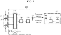
- FIG. 2 is an exemplary diagram showing the detailed configuration of the master 100 and the slave 200 of FIG. 1 .
- the master 100 includes an antenna MA, a wireless communication circuit 110 and a control unit 120.
- the power required for the operation of the master 100 may be supplied from at least one of the plurality of battery modules 20_1 ⁇ 20_N or an external power source (not shown) such as a lead-acid battery.
- the wireless communication circuit 110 is configured to wirelessly transmit a command packet to the slave 200 through the antenna MA. Additionally, the wireless communication circuit 110 is configured to receive a response packet from the slave 200 through the antenna MA.
- the control unit 120 is operably connected to the wireless communication circuit 110.
- the control unit 120 may determine request information (e.g., cell voltage balancing) to at least one of the plurality of slaves 200_1 ⁇ 200_N based on a signal (e.g., a signal indicating battery information) received through the antenna MA, and wirelessly transmit a command packet including data indicating the request information to at least one of the plurality of slaves 200_1 ⁇ 200_N.
- request information e.g., cell voltage balancing
- a signal e.g., a signal indicating battery information
- the control unit 120 may be implemented, by hardware, using at least one of application specific integrated circuits (ASICs), digital signal processors (DSPs), digital signal processing devices (DSPDs), programmable logic devices (PLDs), field programmable gate arrays (FPGAs), microprocessors and electrical units for performing other functions.
- ASICs application specific integrated circuits
- DSPs digital signal processors
- DSPDs digital signal processing devices
- PLDs programmable logic devices
- FPGAs field programmable gate arrays
- the control unit 120 may have a memory device embedded therein, and the memory device may include, for example, RAM, ROM, register, hard disk, optical recording media or magnetic recording media.
- the memory device may store, update and/or erase programs including various types of control logics that are executed by the control unit 120, and/or data created when the control logics are executed.
- the slave 200 includes an antenna SA, a sensing unit 210, a wireless communication circuit 220 and a control unit 230.
- the sensing unit 210 includes a voltage measurement circuit 211 and a temperature sensor 212.
- the sensing unit 210 may further include a current sensor (not shown).
- the voltage measurement circuit 211 includes at least one voltage sensor.
- the voltage measurement circuit 211 measures a module voltage of the battery module 20.
- the module voltage is a voltage across the battery module 20. Additionally, the voltage measurement circuit 211 may further measure a cell voltage of each battery cell 21 included in the battery module 20. The cell voltage is a voltage across the battery cell 21.
- the voltage measurement circuit 211 transmits a voltage signal indicating the module voltage and the voltage of the cell 21 to the control unit 230.
- the temperature sensor 212 is positioned within a predetermined distance from the battery module 20, and transmits a temperature signal indicating the temperature of the battery module 20 to the control unit 230.
- the current sensor is installed on a current path provided for charging/discharging of the battery pack 10 to measure the current flowing during charging/discharging of the battery pack 10 and transmit a current signal indicating the magnitude and direction of the measured current to the control unit 230.
- the wireless communication circuit 220 is connected to the control unit 230 and the antenna SA.
- the wireless communication circuit 220 may be implemented, by hardware, using Radio Frequency System on Chip (RF SoC).
- the wireless communication circuit 220 may wirelessly transmit data to the master 100 or the slave 200 or wirelessly receive data from the master 100 or the slave 200 through the antenna SA.
- RF SoC Radio Frequency System on Chip
- the control unit 230 may be operably coupled to the sensing unit 210 and the wireless communication circuit 220 to individually control the operation of each of the sensing unit 210 and the wireless communication circuit 220.
- the control unit 230 may be implemented, by hardware, using at least one of application specific integrated circuits (ASICs), digital signal processors (DSPs), digital signal processing devices (DSPDs), programmable logic devices (PLDs), field programmable gate arrays (FPGAs), microprocessors and electrical units for performing other functions.
- ASICs application specific integrated circuits
- DSPs digital signal processors
- DSPDs digital signal processing devices
- PLDs programmable logic devices
- FPGAs field programmable gate arrays
- the control unit 230 may have a memory device embedded therein, and the memory device may include, for example, RAM, ROM, register, hard disk, optical recording media or magnetic recording media.
- the memory device may store, update and/or erase programs including various types of
- the wireless communication circuit 220 is configured to selectively perform at least one of predefined functions in response to the signal from the master 100 or the slave 200 wirelessly received through the antenna SA.
- the wireless communication circuit 220 may measure the signal strength of the received signal.
- the wireless communication circuit 220 may wirelessly transmit a response packet to the master 100 in response to the command packet.
- the response packet is a signal for reporting to the master 100 that the slave 200 succeeded in receiving the command packet.
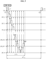
- FIG. 3 is an exemplary timing chart illustrating a process in which the master 100 of FIG. 1 wirelessly collects response packets from the plurality of slaves 200_1 ⁇ 200_N.
- the reference signs RP_1 ⁇ RP_N are given to the N response packets in a sequential order.
- the reference signs RP_1 ⁇ RP_N are given to the N response packets in a sequential order.
- the time point T10 may indicate a start time of an arbitrary cycle
- the time point T20 may indicate a start time of the next cycle.
- a time interval ⁇ T cyc of each cycle is divided into N or more time slots, and N time slots are allocated to the plurality of slaves 200_1 ⁇ 200_N in a sequential order.
- the master 100 wirelessly transmits a command packet CP1 to the plurality of slaves 200_1 ⁇ 200_N.
- the master 100 may wirelessly transmit the command packet CP1 with a predetermined first signal strength.
- the command packet CP1 may be transmitted from the master 100 to the plurality of slaves 200_1 ⁇ 200_N all at once through a broadcasting method.
- the command packet CP1 includes first data D11 and second data D12, and may further include third data D13.
- the first data D11 indicates whether the corresponding command packet CP1 was transmitted by the master 100 for the first time in the current cycle.
- the first data D11 being a first value (e.g., 0) indicates that the corresponding command packet CP1 is transmitted for the first time in the current cycle.
- the second data D12 includes request information to the plurality of slaves 200_1 ⁇ 200_N.
- the request information is for requesting a slave belonging to the second group to perform a specific function (e.g., voltage measurement, cell voltage balancing).
- the third data D13 may include the IDs of all of the plurality of slaves 200_1 ⁇ 200_N.
- Each of the plurality of slaves 200_1 ⁇ 200_N wirelessly transmits a response packet RP at the time slot allocated to each slave 200_1 ⁇ 200_N when wirelessly receiving the command packet CP1.
- the slave 200_i wirelessly transmits the response packet RP at the i th time slot among the N or more time slots.
- the response packet RP_i includes the i th ID allocated to the slave 200_i and the i th battery information indicating the condition of the battery module 20_i.
- the response packet RP_i may be wirelessly transmitted by a broadcasting method with a predetermined second signal strength or a reference signal strength allocated to the slave 200_i. Accordingly, the response packet RP_i may be received by not only the master 100 but also slaves (e.g., 200_i-1, 200_i+1) other than the slave 200_i.
- the k+1 th slave 200_k+1 is configured to stand by to receive the response packet (e.g., RP_k) from at least one slave (e.g., 200_k) having an ID of higher rank than the ID of the k+1 th slave 200_k+1 for a k+1 th preparation period, and wirelessly transmit the k+1 th response packet RP_k+1.
- the response packet e.g., RP_k
- the k+1 th preparation period may be i) a period of time from the time point at which the command packet CP1 was received by the k+1 th slave 200_k+1 to the time point at which a predetermined period of time has passed from the reception of the command packet CP1, or ii) a period of time from the time point at which the command packet CP1 was received by the k+1 th slave 200_k+1 to the time point at which the time slot allocated to the k+1 th slave 200_k+1 is reached.
- the k+1 th response packet RP_k+1 includes the k+1 th ID and the k+1 th battery information, and even the k th ID and the k th battery information included in the k th response packet RP_k.
- the k+1 th slave 200_k+1 succeeds in receiving an additional response packet (e.g., RP_k-1) other than the k th response packet RP_k
- the k+1 th response packet RP_k+1 may further include the k-1 th ID and the k-1 th battery information.
- the k+1 th response packet RP_k+1 includes the k+1 th ID and the k+1 th battery information, but does not include the k th ID and the k th battery information.
- the N th slave 200_N may wirelessly transmit the N th response packet RP_N at least two times. For example, the N th slave 200_N may wirelessly transmit the N th response packet RP_N for the first time in response to the command packet CP1, and after that, wirelessly transmit the N th response packet RP_N again one or more times in a predetermined time.
- the N-1 th slave 200_N-1 may wirelessly transmit an additional response packet RPA_N-1.
- the additional response packet RPA_N-1 includes the N-1 th ID and the N-1 th battery information, and further includes the N th ID and the N th battery information.
- the additional response packet RPA_N-1 may be wirelessly transmitted with the predetermined second signal strength or the reference signal strength allocated to the slave 200_N-1.
- the master 100 scans the response packets RP_1 ⁇ RP_N from the plurality of slaves 200_1 ⁇ 200_N for a predetermined period of time ⁇ T1 from the time point T10.
- the master 100 may terminate the process of wirelessly collecting the first to N th battery information from the plurality of slaves 200_1 ⁇ 200_N.
- each of the first to N th battery information is wirelessly transmitted to the master 100 two or more times, thereby reducing the likelihood that the master 100 fails to collect at least one of the first to N th battery information.
- FIG. 3 shows a situation in which the master 100 received all the response packets RP_1 ⁇ RP_N within the predetermined period of time ⁇ T1 from the time point T10.
- the master 100 failed to receive at least one of the response packets RP_1 ⁇ RP_N within the predetermined period of time ⁇ T1 from the time point T10 will be described with reference to FIG. 4 .
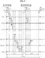
- FIG. 4 is another exemplary timing chart illustrating the process in which the master 100 of FIG. 1 wirelessly collects response packets from the plurality of slaves 200_1 ⁇ 200_N.
- the master 100 wirelessly transmits a command packet CP1 at the time point T10, and scans response packets RP_1 ⁇ RP_N from the plurality of slaves 200_1 ⁇ 200_N for the predetermined period of time ⁇ T1.
- the master 100 receives the response packets RP_1, RP_3 ⁇ RP_N-2, RP_N from the slaves 200_1, 200_3 ⁇ 200_N-2, 200_N within the predetermined period of time ⁇ T1 from the time point T10, but fails to receive the response packets RP_2, RP_N-1 from some slaves 200_2, 200_N-1.
- the response packets RP_2, RP_N-1 may be wirelessly transmitted by the broadcasting method, and the other slaves (e.g., 200_3, 200_N) would have received the response packets RP_2, RP_N-1, respectively.
- the master 100 may set each of the slaves 200_1, 200_3 ⁇ 200_N-2, 200_N to which the IDs included in the response packets RP_1, RP_3 ⁇ RP_N-2, RP_N are allocated as the first group, and each of the remaining slaves 200_2, 200_N-1 as the second group. Additionally, the master 100 may determine a gain value from a lookup table (see the reference number '700' in FIG. 7 ) by using, as an index, the ID (i.e., lowest ranked ID) of the slave 200_N-1 that ranks the lowest among the IDs of the slaves 200_2, 200_N-1 set as the second group (see the step S645 in FIG. 6 and the step S845 in FIG. 8 ).
- the master 100 wirelessly transmits a command packet CP2.
- the master 100 may wirelessly transmit the command packet CP2 with the predetermined first signal strength or a first amplified signal strength.
- the first amplified signal strength may be higher than the first signal strength.
- the command packet CP2 includes first data D21, second data D22 and third data D23, and may further include fourth data D24.
- the first data D21 has a second value (e.g., 1), and the second value indicates that the command packet CP2 is for retrying wireless connection with the second group.
- the second data D22 includes request information to the slaves 200_2, 200_N-1 set as the second group.
- the third data D23 includes the IDs of all the slaves 200_2, 200_N-1 belonging to the second group.
- the command packet CP2 may be received by all the plurality of slave 200_1 ⁇ 200_N, while the command packet CP2 includes only the IDs of the two slaves 200_2, 200_N-1 belonging to the second group, and thus, the slaves 200_1, 200_3 ⁇ 200_N-2, 200_N set as the first group may delete the command packet CP2 from the memory devices thereof.
- each of the slaves 200_2, 200_N-1 belonging to the second group may determine a relative rank of the ID thereof to all the IDs included in the third data D23.
- the slave 200_2 receives the command packet CP2
- the slave 200_2 determines the rank of the ID of the slave 200_2 to be highest since there is no ID having a higher rank than the ID of the slave 200_2 among all the IDs included in the third data D23.
- the slave 200_N-1 may determine the rank of the ID of the slave 200_N-1 to be second highest since there is one ID having a higher rank than the ID of the slave 200_N-1 among all the IDs included in the third data D23.
- the slave 200_2 wirelessly transmits a response packet RP_2' at the timing (i.e., the first time slot) associated with the relative rank of the ID of the slave 200_2.
- Information included in the response packet RP_2' may be the same as the information included in the response packet RP_2.
- the slave 200_N-1 may stand by to receive the response packet RP_2' from the slave 200_2 to which an ID of higher rank than the ID of the slave 200_N-1 is allocated, until the timing associated with the relative rank of the ID of the slave 200_N-1 is reached.
- the slave 200_N-1 receives the response packet RP_2', the slave 200_N-1 transmits a response packet RP_N-1' to the master 100.
- the response packet RP_N-1' may include the N-1 th ID and the N-1 th battery information, and even the second ID and the second battery information included in the response packet RP_2'.
- the response packet RP_N-1' may further include the N-2 th ID and the N-2 th battery information included in the response packet RP_N-2 received before the time point T11.
- the two slaves 200_2, 200_N-1 belonging to the second group may wirelessly transmit the response packets RP_2', RP_N-1' respectively with a predetermined second signal strength or a reference signal strength allocated to each of the slaves 200_2, 200_N-1.
- the reference signal strength allocated to the slave 200_i may be higher than the reference signal strength allocated to the slave 200_i-1. That is, a higher reference signal strength may be allocated to a slave having a longer communication distance with the master 100.
- the master 100 scans the response packets RP_2', RP_N-1' from the slaves 200_2, 200_N-1 belonging to the second group for a predetermined period of time ⁇ T2 from the time point T11.
- ⁇ T2 may be equal to or shorter or longer than ⁇ T1.
- the master 100 may set the slaves 200_2, 200_N-1 from the second group to the first group, and terminate the process of wirelessly collecting the first to N th battery information from the plurality of slaves 200_1 ⁇ 200_N. Accordingly, each of the first to N th battery information is wirelessly transmitted to the master 100 two or more times, thereby reducing the likelihood that the master 100 fails to receive at least one of the first to N th battery information.
- the master 100 may classify the slave (e.g., 200_N-1) into the first group, and maintain the slave (e.g., 200_2) as the second group. Subsequently, the master 100 may wirelessly transmit a new command packet to induce the slave (e.g., 200_2) remaining as the second group to wirelessly transmit the response packet RP_2' again.
- the slave e.g., 200_N-1
- the master 100 may wirelessly transmit a new command packet to induce the slave (e.g., 200_2) remaining as the second group to wirelessly transmit the response packet RP_2' again.
- the 'first command packet' refers to a command packet having the first value as the first data
- the 'second command packet' refers to a command packet having the second value as the first data
- FIG. 5 is a flowchart showing a wireless control method for wirelessly collecting, by the master 100, response packets from the plurality of slaves 200_1 ⁇ 200_N according to the first embodiment of the present disclosure. The method of FIG. 5 may be performed in each predetermined cycle.
- the master 100 wirelessly transmits a first command packet.
- the first command packet may be wirelessly transmitted with the predetermined first signal strength.
- the first command packet includes first data and second data, and may further include third data.
- the first data of the first command packet has the first value indicating that the first command packet is for trying wireless connection with the plurality of slaves 200_1 ⁇ 200_N for the first time in the current cycle.
- the second data of the first command packet includes data for requesting the plurality of slaves 200_1 ⁇ 200_N to perform a specific function (e.g., voltage measurement, cell voltage balancing).
- the third data of the first command packet includes the IDs of the plurality of slaves 200_1 ⁇ 200_N.
- the slave 200_i may perform the function requested by the second data of the first command packet, and wirelessly transmit a response packet RP_i including the ID of the slave 200_i.
- step S520 the master 100 scans the response packets RP_1 ⁇ RP_N from the plurality of slaves 200_1 ⁇ 200_N for a first standby period. That is, the master 100 collects the response packets RP_1 ⁇ RP_N wirelessly transmitted by the plurality of slaves 200_1 ⁇ 200_N until a predetermined period of time has passed from the time point at which the first command packet was transmitted.
- the master 100 classifies each of the plurality of slaves 200_1 ⁇ 200_N as any one of the first group and the second group.
- the master 100 may classify each slave 200 to which the ID of each response packet scanned for the first standby period is allocated as the first group, and classify the remaining slave 200 as the second group. That is, the slave 200 having not transmitted the response packet or having transmitted the response packet that was not received by the master 100 may be classified as the second group by the master 100.
- step S540 the master 100 determines whether at least one of the plurality of slaves 200_1 ⁇ 200_N is classified as the second group. That is, the master 100 checks if at least one slave 200 is still not wirelessly connected with the master 100 in the current cycle. When a value of the step S540 is "YES”, step S550 is performed. The value of the step S540 being "NO" indicates successful wireless connection of the master 100 with all the plurality of slaves 200_1 ⁇ 200_N, and the wireless control method may end.
- the master 100 wirelessly transmits a second command packet.
- the second command packet may be wirelessly transmitted with the predetermined first signal strength.
- the second command packet includes first data, second data and third data.
- the first data of the second command packet has the second value indicating that the second command packet is for retrying wireless connection between the master 100 and the second group.
- the second data of the second command packet includes data for requesting all the slaves 200 belonging to the second group to perform a specific function.
- the third data of the second command packet includes the IDs of all the slaves 200 belonging to the second group.
- each of the plurality of slaves 200_1 ⁇ 200_N determines whether the third data of the second command packet includes the ID thereof in response to the first data of the second command packet having the second value.
- the slave 200 belonging to the second group performs the function requested by the second data of the second command packet whose the third data includes the ID of the corresponding slave 200, and transmits a response packet including the ID of the corresponding slave 200 with the predetermined second signal strength or the reference signal strength allocated thereto to the master 100.
- the slave 200 belonging to the first group does not transmit a response packet as the second data of the second command packet does not include the ID of the corresponding slave 200, and may delete the second command packet from the memory device of the corresponding slave 200 (i.e., ignore the request made by the third data of the second command packet).
- step S560 the master 100 scans the response packet from the slave 200 classified as the second group for a second standby period. That is, the master 100 collects the response packet wirelessly transmitted by each slave 200 belonging to the second group until a predetermined period of time has passed from the time point at which the second command packet was transmitted.
- step S570 the master 100 classifies each of the plurality of slaves 200_1 ⁇ 200_N as any one of the first group and the second group.
- the master 100 may classify the slave 200 to which the ID of each response packet scanned for the second standby period is allocated from the second group to the first group, and maintain the remaining slave 200 belonging to the second group as the second group.
- the wireless control method may advance to the step S540.
- FIG. 6 is a flowchart showing a wireless control method for wirelessly collecting, by the master 100, response packets from the plurality of slaves 200_1 ⁇ 200_N according to a second embodiment of the present disclosure
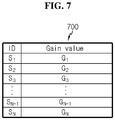
- FIG. 7 is an exemplary diagram of a lookup table 700 associated with the second embodiment. The method of FIG. 6 may be performed in each predetermined cycle.
- the master 100 wirelessly transmits a first command packet.
- the first command packet may be wirelessly transmitted with the predetermined first signal strength.
- the first command packet includes first data and second data, and may further include third data.
- the first data of the first command packet has the first value indicating that the first command packet is for trying wireless connection with the plurality of slaves 200_1 ⁇ 200_N for the first time in the current cycle.
- the second data of the first command packet includes data for requesting the plurality of slaves 200_1 ⁇ 200_N to perform a specific function.
- the third data of the first command packet includes the IDs of the plurality of slaves 200_1 ⁇ 200_N.
- each of the plurality of slaves 200_1 ⁇ 200_N may perform the function requested by the second data of the first command packet, and wirelessly transmit a response packet including the ID thereof with the predetermined second signal strength or the reference signal strength allocated thereto.
- step S620 the master 100 scans the response packets from the plurality of slaves 200_1 ⁇ 200_N for the first standby period. That is, the master 100 collects the response packets wirelessly transmitted by the plurality of slaves 200_1 ⁇ 200_N until a predetermined period of time has passed from the time point at which the first command packet was transmitted.
- the master 100 classifies each of the plurality of slaves 200_1 ⁇ 200_N as any one of the first group and the second group.
- the master 100 may classify the slave 200 to which the ID of each response packet scanned for the first standby period is allocated as the first group, and classify the remaining slave 200 as the second group. That is, the slave 200 having not transmitted the response packet or having transmitted the response packet that was not received by the master 100 may be classified as the second group by the master 100.
- step S640 the master 100 determines whether at least one of the plurality of slaves 200_1 ⁇ 200_N is classified as the second group. That is, the master 100 checks if at least one slave 200 is still not wirelessly connected with the master 100 in the current cycle. When a value of the step S640 is "YES”, step S645 is performed. The value of the step S640 being "NO" indicates that the master 100 is wirelessly connected with all the plurality of slaves 200_1 ⁇ 200_N, and the wireless control method may end.
- step S645 the master 100 determines a first gain value from the lookup table 700 using the lowest ranked ID among the IDs of at least one slave 200 belonging to the second group as an index.
- the lookup table 700 stores a plurality of gain values G 1 ⁇ G N associated with the IDs S 1 ⁇ S N of the plurality of slaves 200_1 ⁇ 200_N, respectively. At least one of the plurality of gain values G 1 ⁇ G N is greater than 1. For example, G 1 > 1.
- a lower ranked ID is associated with a larger gain value.
- S i 1 ⁇ N
- S i is the ID of the slave 200_i, and is associated with Gi, Gi-i ⁇ Gi.
- S N-1 is the lowest ranked ID, and thus G N-1 is determined as the first gain value.
- step S650 the master 100 wirelessly transmits a second command packet with the first amplified signal strength.
- the first amplified signal strength equals to the first signal strength multiplied by the first gain value determined in the step S645.
- the second command packet includes first data, second data and third data.
- the first data of the second command packet has the second value indicating that the second command packet is for retrying wireless connection between the master 100 and the second group.
- the second data of the second command packet includes data for requesting all the slaves 200 belonging to the second group to perform a specific function.
- the third data of the second command packet includes the IDs of all the slaves 200 belonging to the second group.
- each of the plurality of slaves 200_1 ⁇ 200_N determines whether the second data of the second command packet has the ID thereof in response to the first data of the second command packet having the second value.
- the slave 200 belonging to the second group performs the function requested by the second data of the second command packet whose the third data includes the ID of the corresponding slave 200, and transmits a response packet including the ID of the corresponding slave 200 with the predetermined second signal strength or the reference signal strength allocated to the corresponding slave 200 to the master 100.
- the slave 200 belonging to the first group does not transmit the response packet as the second data of the second command packet does not include the ID of the corresponding slave 200, and may delete the second command packet from the memory device of the corresponding slave 200 (i.e., ignore the request made by the third data of the second command packet).
- step S660 the master 100 scans the response packet from the slave 200 classified as the second group for the second standby period. That is, the master 100 collects the response packet wirelessly transmitted by each slave 200 belonging to the second group from the time point at which the second command packet was transmitted to the time point at which a predetermined period of time has passed from the transmission of the second command packet.
- step S670 the master 100 classifies each of the plurality of slaves 200_1 ⁇ 200_N as any one of the first group and the second group.
- the master 100 may classify the slave 200 to which the ID of each response packet scanned for the second standby period is allocated from the second group to the first group, and maintain the remaining slave 200 belonging to the second group as the second group.
- the wireless control method may move to the step S640.
- FIG. 8 is a flowchart showing a method for wirelessly collecting, by the master 100, response packets from the plurality of slaves 200_1 ⁇ 200_N according to a third embodiment of the present disclosure.
- the method of FIG. 8 may be performed in each predetermined cycle.
- the lookup table 700 shown in FIG. 7 may be referenced by the master 100 in not only the second embodiment but also the third embodiment.
- the master 100 wirelessly transmits a first command packet.
- the first command packet may be wirelessly transmitted with the predetermined first signal strength.
- the first command packet includes first data and second data, and may further include third data.
- the first data of the first command packet has the first value indicating that the first command packet is for trying wireless connection with the plurality of slaves 200_1 ⁇ 200_N for the first time in the current cycle.
- the second data of the first command packet includes data for requesting the plurality of slaves 200_1 ⁇ 200_N to perform a specific function.
- the third data of the first command packet includes the IDs of the plurality of slaves 200_1 ⁇ 200_N.
- each of the plurality of slaves 200_1 ⁇ 200_N may perform the function requested by the second data of the first command packet, and wirelessly transmit the response packet including the ID thereof with the predetermined second signal strength or the reference signal strength allocated thereto.
- step S820 the master 100 scans the response packets from the plurality of slaves 200_1 ⁇ 200_N for the first standby period. That is, the master 100 collects the response packet wirelessly transmitted by the plurality of slaves 200_1 ⁇ 200_N from the time point at which the first command packet was transmitted to the time point at which a predetermined period of time has passed from the transmission of the first command packet.
- the master 100 classifies each of the plurality of slaves 200_1 ⁇ 200_N as any one of the first group and the second group.
- the master 100 may classify the slave 200 to which the ID of each response packet scanned for the first standby period is allocated as the first group, and classify the remaining slave 200 as the second group. That is, the slave 200 having not transmitted the response packet or having transmitted the response packet that was not received by the master 100 may be classified as the second group by the master 100.
- step S840 the master 100 determines whether at least one of the plurality of slaves 200_1 ⁇ 200_N is classified as the second group. That is, the master 100 checks if at least one slave 200 is still not wirelessly connected with the master 100 in the current cycle. When a value of the step S840 is "YES”, step S845 is performed. The value of the step S840 being "NO" indicates that the master 100 is wirelessly connected with all the plurality of slaves 200_1 ⁇ 200_N, and the wireless control method may end.
- step S845 the master 100 determines a second gain value.
- the master 100 determines the second gain value from the lookup table 700 by using as an index, the lowest ranked ID among the IDs of at least one slave 200 belonging to the second group.
- S N-1 is the lowest ranked ID, and thus G N-1 is determined as the second gain value.
- the master 100 wirelessly transmits a second command packet.
- the second command packet may be wirelessly transmitted with the predetermined first signal strength or the first amplified signal strength.
- the first amplified signal strength may be determined by the method described with reference to FIGS. 6 and 7 .
- the second command packet includes first data, second data and third data, and further includes fourth data.
- the first data of the second command packet has the second value indicating that the second command packet is for retrying wireless connection between the master 100 and the second group.
- the second data of the second command packet includes data for requesting all the slaves 200 belonging to the second group to perform a specific function.
- the third data of the second command packet includes the IDs of all the slaves 200 belonging to the second group.
- the second command packet further includes fourth data.
- the fourth data of the second command packet indicates the second gain value determined in the step S845.
- each of the plurality of slaves 200_1 ⁇ 200_N determines whether the third data of the second command packet includes the ID thereof in response to the first data of the second command packet having the second value.
- the slave 200 belonging to the second group may perform the function requested by the second data of the second command packet whose the third data includes the ID of the slave 200.
- the slave 200 belonging to the second group determines a second amplified signal strength by multiplying the predetermined second signal strength or the reference signal strength allocated to the corresponding slave 200 by the second gain value indicated by the fourth data of the second command packet. Subsequently, each slave 200 belonging to the second group transmits a response packet including the ID of the corresponding slave 200 to the master 100 with the second amplified signal strength. In contrast, the slave 200 belonging to the first group does not transmit a response packet as the second data of the second command packet does not include the ID of the corresponding slave 200, and may delete the second command packet from the memory device of the corresponding slave 200 (i.e., ignore the request made by the third data of the second command packet).
- step S860 the master 100 scans the response packet from the slave 200 classified as the second group for the second standby period. That is, the master 100 collects the response packet wirelessly transmitted by each slave 200 belonging to the second group until a predetermined period of time has passed from the time point at which the second command packet was transmitted.
- step S870 the master 100 classifies each of the plurality of slaves 200_1 ⁇ 200_N as any one of the first group and the second group.
- the master 100 may classify the slave 200 to which the ID of each response packet scanned for the second standby period is allocated from the second group to the first group, and maintain the remaining slave 200 belonging to the second group as the second group.
- the wireless control method may move to the step S840.
Landscapes
- Engineering & Computer Science (AREA)
- Computer Networks & Wireless Communication (AREA)
- Signal Processing (AREA)
- General Physics & Mathematics (AREA)
- Physics & Mathematics (AREA)
- Electrochemistry (AREA)
- General Chemical & Material Sciences (AREA)
- Chemical Kinetics & Catalysis (AREA)
- Chemical & Material Sciences (AREA)
- Manufacturing & Machinery (AREA)
- Computing Systems (AREA)
- Health & Medical Sciences (AREA)
- General Health & Medical Sciences (AREA)
- Medical Informatics (AREA)
- Computer Security & Cryptography (AREA)
- Mobile Radio Communication Systems (AREA)
- Charge And Discharge Circuits For Batteries Or The Like (AREA)
- Secondary Cells (AREA)
Abstract
Description
- The present disclosure relates to a wireless control system and a wireless control method for wirelessly collecting battery information and a battery pack including the wireless control system.
- The present application claims priority to Korean Patent Application No.
10-2018-0144857 - Recently, there is dramatically growing demand for portable electronic products such as laptop computers, video cameras and mobile phones, and with the extensive development of electric vehicles, accumulators for energy storage, robots and satellites, many studies are being made on high performance batteries that can be recharged repeatedly.
- Currently, commercially available batteries include nickel-cadmium batteries, nickel-hydrogen batteries, nickel-zinc batteries, lithium batteries and the like, and among them, lithium batteries have little or no memory effect, and thus they are gaining more attention than nickel-based batteries for their advantages that recharging can be done whenever it is convenient, the self-discharge rate is very low and the energy density is high.
- A battery pack for a device requiring high capacity and high voltage such as an electric vehicle generally includes a plurality of battery modules connected in series. To manage the condition of the plurality of battery modules individually and efficiently, a control system having multi-slave is disclosed. The control system having multi-slave includes a plurality of slaves for monitoring the condition of each battery module and a master that controls the entire operation of the plurality of slaves.
- However, when wireless communication is carried out between the master and the plurality of slaves, wireless connection between the master and at least one slave may be unwantedly disconnected due to external noise.
- The present disclosure is designed to solve the above-described problem, and therefore the present disclosure is directed to providing a wireless control system, a wireless control method and a battery pack, in which at least one slave wirelessly forwards, to the master, not only battery information of a battery module coupled to the slave, but also an additional battery information from other slave, so that the master may wirelessly collect battery information indicating the condition of each of a plurality of battery modules with high reliability.
- These and other objects and advantages of the present disclosure may be understood by the following description and will be apparent from the embodiments of the present disclosure. In addition, it will be readily understood that the objects and advantages of the present disclosure may be realized by the means set forth in the appended claims and a combination thereof.
- A wireless control system according to an aspect of the present disclosure is for wirelessly collecting battery information of each of first to Nth battery modules. The wireless control system includes a master configured to wirelessly transmit a first command packet, and first to Nth slaves to which first to Nth identifications (IDs) are allocated, respectively. The first slave is configured to wirelessly transmit a first response packet including first battery information indicating a condition of the first battery module and the first ID, when the first slave receives the first command packet. A k+1th slave is configured to, when the k+1th slave receives the first command packet, stand by to receive a kth response packet from a kth slave for a preparation period, and wirelessly transmit a k+1th response packet including k+1th battery information indicating a condition of the k+1th battery module and a k+1th ID. When the kth response packet is received by the k+1th slave within the preparation period, the k+1th response packet further includes kth battery information indicating a condition of a kth battery module and a kth ID. N is a natural number of 2 or greater, and k is a natural number of 1 or greater and N-1 or smaller.
- The Nth slave may be configured to wirelessly transmit an Nth response packet including Nth battery information indicating a condition of the Nth battery module and the Nth ID at least two times, when the Nth slave receives the first command packet.
- The Nth slave may be configured to wirelessly transmit an Nth response packet including Nth battery information indicating a condition of the Nth battery module and the Nth ID, when the Nth slave receives the first command packet. An N-1th slave may be configured to wirelessly transmit an additional response packet including the Nth battery information and the Nth ID, when the N-1th slave receives the Nth response packet.
- The k+1th response packet does not include the kth ID and the kth battery information, when the kth response packet is not received by the k+1th slave within the preparation period.
- The master may be configured to set the k+1th slave as a first group, when the k+1th response packet is received by the master within a predetermined period of time from a time point at which the first command packet was wirelessly transmitted. The master may be configured to set the k+1th slave as a second group, when the k+1th response packet is not received by the master within the predetermined period of time from the time point at which the first command packet was wirelessly transmitted.
- The master may be configured to wirelessly transmit a second command packet, when at least one of the first to Nth slaves is set as the second group. The second command packet includes the IDs of each slave set as the second group.
- The master may be configured to wirelessly transmit the first command packet with a first signal strength. The master may be configured to wirelessly transmit the second command packet with a first amplified signal strength. The first amplified signal strength is higher than the first signal strength.
- The k+1th slave may be configured to wirelessly transmit the k+1th response packet, when the second command packet includes the k+1th ID.
- The k+1th slave may be configured to determine a relative rank of the k+1th ID among all the IDs included in the second command packet, when the second command packet includes the k+1th ID. The k+1th slave may be configured to wirelessly transmit the k+1th response packet at a time slot associated with the relative rank.
- A battery pack according to another aspect of the present disclosure includes the wireless control system.
- A wireless control method according to still another aspect of the present disclosure is for wirelessly collecting, by a master, first to Nth battery information indicating conditions of first to Nth battery modules from first to Nth slaves to which first to Nth identifications (IDs) are allocated, respectively. The wireless control method includes wirelessly transmitting, by the master, a first command packet to the first to Nth slaves, wirelessly transmitting, by the first slave, a first response packet including the first battery information and the first ID when the first slave receives the first command packet, and standing by, by a k+1th slave, to receive a kth response packet from a kth slave for a preparation period, and wirelessly transmitting a k+1th response packet including k+1th battery information and a k+1th ID, when the k+1th slave receives the first command packet. The k+1th response packet further includes kth battery information indicating the condition of a kth battery module and the kth ID when a kth response packet is received by the k+1th slave within the preparation period. N is a natural number of 2 or greater, and k is a natural number of 1 or greater and N-1 or smaller.
- The wireless control method may further include wirelessly transmitting, by the Nth slave, an Nth response packet including the Nth battery information and the Nth ID at least two times, when the Nth slave receives the first command packet.
- The wireless control method may further include wirelessly transmitting, by the Nth slave, an Nth response packet including the Nth battery information and the Nth ID, when the Nth slave receives the first command packet, and wirelessly transmitting, by an N-1th slave, an additional response packet including the Nth battery information and the Nth ID, when the N-1th slave receives the Nth response packet.
- According to at least one of the embodiments of the present disclosure, at least one slave may wirelessly forward not only battery information of a battery module coupled to the slave, but also an additional battery information from other slave, to the master.
- In addition, according to at least one of the embodiments of the present disclosure, the master may only select each slave having failed wireless connection with the master among all the slaves and retry wireless connection with the selected slave.
- Furthermore, according to at least one of the embodiments of the present disclosure, when wireless connection between the master and a specific slave fails, the master may wirelessly transmit a signal having higher signal strength than normal condition (i.e., when wireless connection is established) to the specific slave.
- As a result, the master may wirelessly collect battery information indicating the condition of each of the plurality of battery modules with high reliability.
- The effects of the present disclosure are not limited to the effects mentioned above, and these and other effects will be clearly understood by those skilled in the art from the appended claims.
- The accompanying drawings illustrate a preferred embodiment of the present disclosure, and together with the detailed description of the present disclosure described below, serve to provide a further understanding of the technical aspects of the present disclosure, and thus the present disclosure should not be construed as being limited to the drawings.
-
FIG. 1 is an exemplary diagram showing the configuration of a battery pack including a wireless control system. -
FIG. 2 is an exemplary diagram showing the detailed configuration of a master and a slave ofFIG. 1 . -
FIG. 3 is an exemplary timing chart illustrating a process in which a master ofFIG. 1 wirelessly collects response packets from a plurality of slaves. -
FIG. 4 is another exemplary timing chart illustrating a process in which a master ofFIG. 1 wirelessly collects response packets from a plurality of slaves. -
FIG. 5 is a flowchart showing a method for wirelessly collecting, by a master, response packets from a plurality of slaves according to a first embodiment of the present disclosure. -
FIG. 6 is a flowchart showing a method for wirelessly collecting, by a master, response packets from a plurality of slaves according to a second embodiment of the present disclosure. -
FIG. 7 is an exemplary diagram of a lookup table associated with a second embodiment. -
FIG. 8 is a flowchart showing a method for wirelessly collecting, by a master, response packets from a plurality of slaves according to a third embodiment of the present disclosure. - Hereinafter, the preferred embodiments of the present disclosure will be described in detail with reference to the accompanying drawings. Prior to the description, it should be understood that the terms or words used in the specification and the appended claims should not be construed as being limited to general and dictionary meanings, but interpreted based on the meanings and concepts corresponding to the technical aspects of the present disclosure on the basis of the principle that the inventor is allowed to define the terms appropriately for the best explanation.
- Therefore, the embodiments described herein and illustrations shown in the drawings are just a most preferred embodiment of the present disclosure, but not intended to fully describe the technical aspects of the present disclosure, so it should be understood that a variety of other equivalents and modifications could be made thereto at the time of filing the application.
- Additionally, in describing the present disclosure, when it is deemed that a certain detailed description of relevant known elements or functions renders the key subject matter of the present disclosure ambiguous, the detailed description is omitted herein.
- The terms including the ordinal number such as "first", "second" and the like, are used to distinguish one element from another among various elements, but not intended to limit the elements by the terms.
- Unless the context clearly indicates otherwise, it will be understood that the term "comprises" when used in this specification, specifies the presence of stated elements, but does not preclude the presence or addition of one or more other elements. Additionally, the term <control unit> as used herein refers to a processing unit of at least one function or operation, and this may be implemented by hardware or software alone or in combination.
- In addition, throughout the specification, it will be further understood that when an element is referred to as being "connected to" another element, it can be directly connected to the other element or intervening elements may be present.
-
FIG. 1 is an exemplary diagram showing the configuration of abattery pack 10 including awireless control system 30 according to an embodiment of the present disclosure. - Referring to
FIG. 1 , thebattery pack 10 includes N battery modules 20 and thewireless control system 30. N is a natural number of 2 or greater. In the drawing, to identify the N battery modules 20, the reference signs 20_1∼20_N are given to the N battery modules 20 in a sequential order. Thebattery pack 10 may be mounted in an electric vehicle to supply power required to drive an electric motor of the electric vehicle. - The N battery modules 20_1∼20_N are electrically connected in series and/or in parallel. Each battery module 20 includes at least one
battery cell 21. - The
wireless control system 30 includes amaster 100 andN slaves 200. In the drawing, to identify theN slaves 200, the reference signs 200_1∼200_N are given to theN slaves 200 in a sequential order. - The
master 100 is configured to control theentire battery pack 10. Each of the plurality of slaves 200_1∼200_N is configured to perform wireless communication with themaster 100 using an ID of each slave 200_1∼200_N allocated from themaster 100. Themaster 100 stores the IDs allocated to the plurality of slaves 200_1∼200_N. The IDs are identification information for identifying the plurality of slaves 200_1∼200_N. - The
master 100 may communicate with an external main controller (e.g., an electronic control unit (ECU) of the electric vehicle) via a wired network such as Controller Area Network (CAN). Themaster 100 includes a master antenna MA, and may wirelessly communicate with eachslave 200 through the master antenna MA. - The plurality of slaves 200_1∼200_N is provided to the plurality of battery modules 20_1∼20_N one-to-one. When i = 1 ∼ N, the slave 200_i is electrically connected to positive and negative terminals of each
battery cell 21 of the battery module 20_i, and is configured to monitor the condition (e.g., voltage, current, temperature) of the battery module 20_i. The power required for the operation of the slave 200_i may be supplied from the battery module 20_i. - Additionally, the slave 200_i may wirelessly transmit data (hereinafter referred to as 'battery information') indicating the monitored condition of the battery module 20_i to the
master 100. - The
master 100 may calculate a state of charge (SOC) and a state of health (SOH) of the battery module 20_i, or determine overvoltage, undervoltage, overcharge or overdischarge of eachbattery cell 21 of the battery module 20_i, based on the battery information from the slave 200_i. - The slaves 200_1∼200_N is positioned at different areas inside the
battery pack 10 such that communication distances to themaster 100 are different to each other. The communication distance between the slave 200_i and themaster 100 may be a straight line distance between the antenna SA_i of the slave 200_i and the antenna MA of themaster 100. Hereinafter, it is assumed that the communication distance between the slave 200_i and themaster 100 is shorter than the communication distance between the slave 200_i+1 and themaster 100. For example, referring toFIG. 1 , the antenna SA_i of the slave 200_i is positioned closer to the antenna MA of themaster 100 than the antenna SA_i+1 of theslave 200_i+ 1. The antenna SA_i of the slave 200_i may be said to be positioned on the 'upstream side' of the antenna SA_i+1 of theslave 200_i+ 1, and the antenna SA_i+1 of the slave 200_i+1 may be said to be positioned on the 'downstream side' of the antenna SA_i of the slave 200_i. - Hereinafter, it is assumed that an ID of higher rank is allocated to a slave having a shorter communication distance with the
master 100. For example, the rank of the ID of the slave 200_i is higher than the rank of the ID of theslave 200_i+ 1. - The
master 100 is configured to classify each of the plurality of slaves 200_1∼200_N into any one of a first group and a second group in each predetermined cycle. Themaster 100 may scan a response packet from the second group for a standby period from the time point at which themaster 100 wirelessly transmitted a command packet. - When the command packet includes the ID of the
slave 200, thecorresponding slave 200 may be configured to wirelessly transmit a response packet to themaster 100 in response to the command packet. - When the
master 100 receives a response packet from a specific slave (e.g., 200_2) belonging to the second group within a predetermined period of time from the time point at which the command packet was transmitted, themaster 100 classifies the corresponding specific slave from the second group to the first group. On the contrary, when themaster 100 does not receive a response packet from the specific slave belonging to the second group for the predetermined period of time from the time point at which the command packet was transmitted, themaster 100 maintains the corresponding specific slave as the second group. -
FIG. 2 is an exemplary diagram showing the detailed configuration of themaster 100 and theslave 200 ofFIG. 1 . - Referring to
FIG. 2 , themaster 100 includes an antenna MA, awireless communication circuit 110 and acontrol unit 120. The power required for the operation of themaster 100 may be supplied from at least one of the plurality of battery modules 20_1∼20_N or an external power source (not shown) such as a lead-acid battery. - The
wireless communication circuit 110 is configured to wirelessly transmit a command packet to theslave 200 through the antenna MA. Additionally, thewireless communication circuit 110 is configured to receive a response packet from theslave 200 through the antenna MA. - The
control unit 120 is operably connected to thewireless communication circuit 110. Thecontrol unit 120 may determine request information (e.g., cell voltage balancing) to at least one of the plurality of slaves 200_1∼200_N based on a signal (e.g., a signal indicating battery information) received through the antenna MA, and wirelessly transmit a command packet including data indicating the request information to at least one of the plurality of slaves 200_1∼200_N. - The
control unit 120 may be implemented, by hardware, using at least one of application specific integrated circuits (ASICs), digital signal processors (DSPs), digital signal processing devices (DSPDs), programmable logic devices (PLDs), field programmable gate arrays (FPGAs), microprocessors and electrical units for performing other functions. Thecontrol unit 120 may have a memory device embedded therein, and the memory device may include, for example, RAM, ROM, register, hard disk, optical recording media or magnetic recording media. The memory device may store, update and/or erase programs including various types of control logics that are executed by thecontrol unit 120, and/or data created when the control logics are executed. - The
slave 200 includes an antenna SA, asensing unit 210, awireless communication circuit 220 and acontrol unit 230. - The
sensing unit 210 includes a voltage measurement circuit 211 and a temperature sensor 212. Thesensing unit 210 may further include a current sensor (not shown). The voltage measurement circuit 211 includes at least one voltage sensor. - The voltage measurement circuit 211 measures a module voltage of the battery module 20. The module voltage is a voltage across the battery module 20. Additionally, the voltage measurement circuit 211 may further measure a cell voltage of each
battery cell 21 included in the battery module 20. The cell voltage is a voltage across thebattery cell 21. The voltage measurement circuit 211 transmits a voltage signal indicating the module voltage and the voltage of thecell 21 to thecontrol unit 230. - The temperature sensor 212 is positioned within a predetermined distance from the battery module 20, and transmits a temperature signal indicating the temperature of the battery module 20 to the
control unit 230. - The current sensor is installed on a current path provided for charging/discharging of the
battery pack 10 to measure the current flowing during charging/discharging of thebattery pack 10 and transmit a current signal indicating the magnitude and direction of the measured current to thecontrol unit 230. - The
wireless communication circuit 220 is connected to thecontrol unit 230 and the antenna SA. Thewireless communication circuit 220 may be implemented, by hardware, using Radio Frequency System on Chip (RF SoC). Thewireless communication circuit 220 may wirelessly transmit data to themaster 100 or theslave 200 or wirelessly receive data from themaster 100 or theslave 200 through the antenna SA. - The
control unit 230 may be operably coupled to thesensing unit 210 and thewireless communication circuit 220 to individually control the operation of each of thesensing unit 210 and thewireless communication circuit 220. Thecontrol unit 230 may be implemented, by hardware, using at least one of application specific integrated circuits (ASICs), digital signal processors (DSPs), digital signal processing devices (DSPDs), programmable logic devices (PLDs), field programmable gate arrays (FPGAs), microprocessors and electrical units for performing other functions. Thecontrol unit 230 may have a memory device embedded therein, and the memory device may include, for example, RAM, ROM, register, hard disk, optical recording media or magnetic recording media. The memory device may store, update and/or erase programs including various types of control logics that are executed by thecontrol unit 230, and/or data created when the control logics are executed. - The
wireless communication circuit 220 is configured to selectively perform at least one of predefined functions in response to the signal from themaster 100 or theslave 200 wirelessly received through the antenna SA. - When a signal is received through the antenna SA, the
wireless communication circuit 220 may measure the signal strength of the received signal. When thewireless communication circuit 220 receives the command packet from themaster 100 through the antenna SA, thewireless communication circuit 220 may wirelessly transmit a response packet to themaster 100 in response to the command packet. The response packet is a signal for reporting to themaster 100 that theslave 200 succeeded in receiving the command packet. -
FIG. 3 is an exemplary timing chart illustrating a process in which themaster 100 ofFIG. 1 wirelessly collects response packets from the plurality of slaves 200_1∼200_N. To identify the response packets from the N slaves 200_1∼200_N, the reference signs RP_1∼RP_N are given to the N response packets in a sequential order. - In
FIG. 3 , to identify the response packets from the N slaves 200_1∼200_N, the reference signs RP_1∼RP_N are given to the N response packets in a sequential order. InFIG. 3 , the time point T10 may indicate a start time of an arbitrary cycle, and the time point T20 may indicate a start time of the next cycle. Additionally, it is assumed that a time interval ΔTcyc of each cycle is divided into N or more time slots, and N time slots are allocated to the plurality of slaves 200_1∼200_N in a sequential order. - At the time point T10, the
master 100 wirelessly transmits a command packet CP1 to the plurality of slaves 200_1∼200_N. Themaster 100 may wirelessly transmit the command packet CP1 with a predetermined first signal strength. The command packet CP1 may be transmitted from themaster 100 to the plurality of slaves 200_1∼200_N all at once through a broadcasting method. The command packet CP1 includes first data D11 and second data D12, and may further include third data D13. The first data D11 indicates whether the corresponding command packet CP1 was transmitted by themaster 100 for the first time in the current cycle. For example, the first data D11 being a first value (e.g., 0) indicates that the corresponding command packet CP1 is transmitted for the first time in the current cycle. The second data D12 includes request information to the plurality of slaves 200_1∼200_N. The request information is for requesting a slave belonging to the second group to perform a specific function (e.g., voltage measurement, cell voltage balancing). The third data D13 may include the IDs of all of the plurality of slaves 200_1∼200_N. - Each of the plurality of slaves 200_1∼200_N wirelessly transmits a response packet RP at the time slot allocated to each slave 200_1∼200_N when wirelessly receiving the command packet CP1.
- When i = 1 ∼ N, the slave 200_i wirelessly transmits the response packet RP at the ith time slot among the N or more time slots. The response packet RP_i includes the ith ID allocated to the slave 200_i and the ith battery information indicating the condition of the battery module 20_i. The response packet RP_i may be wirelessly transmitted by a broadcasting method with a predetermined second signal strength or a reference signal strength allocated to the slave 200_i. Accordingly, the response packet RP_i may be received by not only the
master 100 but also slaves (e.g., 200_i-1, 200_i+1) other than the slave 200_i. - When k = 1 ∼ N-1, the k+1th slave 200_k+1 is configured to stand by to receive the response packet (e.g., RP_k) from at least one slave (e.g., 200_k) having an ID of higher rank than the ID of the k+1th slave 200_k+1 for a k+1th preparation period, and wirelessly transmit the k+1th response
packet RP_k+ 1. The k+1th preparation period may be i) a period of time from the time point at which the command packet CP1 was received by the k+1th slave 200_k+1 to the time point at which a predetermined period of time has passed from the reception of the command packet CP1, or ii) a period of time from the time point at which the command packet CP1 was received by the k+1th slave 200_k+1 to the time point at which the time slot allocated to the k+1th slave 200_k+1 is reached. - When the k+1th slave 200_k+1 succeeds in receiving the kth response packet RP_k within the k+1th preparation period, the k+1th response packet RP_k+1 includes the k+1th ID and the k+1th battery information, and even the kth ID and the kth battery information included in the kth response packet RP_k. When the k+1th slave 200_k+1 succeeds in receiving an additional response packet (e.g., RP_k-1) other than the kth response packet RP_k, the k+1th response packet RP_k+1 may further include the k-1th ID and the k-1th battery information.
- On the contrary, when the k+1th slave 200_k+1 fails to receive the kth response packet RP_k within the k+1th preparation period, the k+1th response packet RP_k+1 includes the k+1th ID and the k+1th battery information, but does not include the kth ID and the kth battery information.
- When the Nth slave 200_N receives the command packet CP1, the Nth slave 200_N may wirelessly transmit the Nth response packet RP_N at least two times. For example, the Nth slave 200_N may wirelessly transmit the Nth response packet RP_N for the first time in response to the command packet CP1, and after that, wirelessly transmit the Nth response packet RP_N again one or more times in a predetermined time.
- Alternatively, when the N-1th slave 200_N-1 receives the Nth response packet RP_N after wirelessly transmitting the N-1th response packet RP_N-1, the N-1th slave 200_N-1 may wirelessly transmit an additional response packet RPA_N-1. The additional response packet RPA_N-1 includes the N-1th ID and the N-1th battery information, and further includes the Nth ID and the Nth battery information. The additional response packet RPA_N-1 may be wirelessly transmitted with the predetermined second signal strength or the reference signal strength allocated to the slave 200_N-1.
- The
master 100 scans the response packets RP_1∼RP_N from the plurality of slaves 200_1∼200_N for a predetermined period of time ΔT1 from the time point T10. When themaster 100 succeeds in receiving the response packets RP_1∼RP_N from the first to Nth slaves 200_1∼200_N within the predetermined period of time ΔT1 from the time point T10, themaster 100 may terminate the process of wirelessly collecting the first to Nth battery information from the plurality of slaves 200_1∼200_N. Accordingly, within the period of time from the time point T10 until the time point T20 is reached, each of the first to Nth battery information is wirelessly transmitted to themaster 100 two or more times, thereby reducing the likelihood that themaster 100 fails to collect at least one of the first to Nth battery information. -
FIG. 3 shows a situation in which themaster 100 received all the response packets RP_1∼RP_N within the predetermined period of time ΔT1 from the time point T10. Below is the operation when themaster 100 failed to receive at least one of the response packets RP_1∼RP_N within the predetermined period of time ΔT1 from the time point T10 will be described with reference toFIG. 4 . -
FIG. 4 is another exemplary timing chart illustrating the process in which themaster 100 ofFIG. 1 wirelessly collects response packets from the plurality of slaves 200_1∼200_N. - Referring to
FIG. 4 , in the same way asFIG. 3 , themaster 100 wirelessly transmits a command packet CP1 at the time point T10, and scans response packets RP_1∼RP_N from the plurality of slaves 200_1∼200_N for the predetermined period of time ΔT1. - As opposed to the situation of
FIG. 3 , themaster 100 receives the response packets RP_1, RP_3∼RP_N-2, RP_N from the slaves 200_1, 200_3∼200_N-2, 200_N within the predetermined period of time ΔT1 from the time point T10, but fails to receive the response packets RP_2, RP_N-1 from some slaves 200_2, 200_N-1. Meanwhile, the response packets RP_2, RP_N-1 may be wirelessly transmitted by the broadcasting method, and the other slaves (e.g., 200_3, 200_N) would have received the response packets RP_2, RP_N-1, respectively. - Then, the
master 100 may set each of the slaves 200_1, 200_3∼200_N-2, 200_N to which the IDs included in the response packets RP_1, RP_3∼RP_N-2, RP_N are allocated as the first group, and each of the remaining slaves 200_2, 200_N-1 as the second group. Additionally, themaster 100 may determine a gain value from a lookup table (see the reference number '700' inFIG. 7 ) by using, as an index, the ID (i.e., lowest ranked ID) of the slave 200_N-1 that ranks the lowest among the IDs of the slaves 200_2, 200_N-1 set as the second group (see the step S645 inFIG. 6 and the step S845 inFIG. 8 ). - At the time point T11, only the two slaves 200_2, 200_N-1 are set as the second group, while the remaining slaves 200_1, 200_3∼200_N-2, 200_N are set as the first group. At the time point T11, the
master 100 wirelessly transmits a command packet CP2. Themaster 100 may wirelessly transmit the command packet CP2 with the predetermined first signal strength or a first amplified signal strength. The first amplified signal strength may be higher than the first signal strength. The command packet CP2 includes first data D21, second data D22 and third data D23, and may further include fourth data D24. The first data D21 has a second value (e.g., 1), and the second value indicates that the command packet CP2 is for retrying wireless connection with the second group. The second data D22 includes request information to the slaves 200_2, 200_N-1 set as the second group. The third data D23 includes the IDs of all the slaves 200_2, 200_N-1 belonging to the second group. The command packet CP2 may be received by all the plurality of slave 200_1 ∼ 200_N, while the command packet CP2 includes only the IDs of the two slaves 200_2, 200_N-1 belonging to the second group, and thus, the slaves 200_1, 200_3∼200_N-2, 200_N set as the first group may delete the command packet CP2 from the memory devices thereof. - In contrast, when each of the slaves 200_2, 200_N-1 belonging to the second group receives the command packet CP2, each of the slaves 200_2, 200_N-1 belonging to the second group may determine a relative rank of the ID thereof to all the IDs included in the third data D23. When the slave 200_2 receives the command packet CP2, the slave 200_2 determines the rank of the ID of the slave 200_2 to be highest since there is no ID having a higher rank than the ID of the slave 200_2 among all the IDs included in the third data D23. When the slave 200_N-1 receives the command packet CP2, the slave 200_N-1 may determine the rank of the ID of the slave 200_N-1 to be second highest since there is one ID having a higher rank than the ID of the slave 200_N-1 among all the IDs included in the third data D23.
- The slave 200_2 wirelessly transmits a response packet RP_2' at the timing (i.e., the first time slot) associated with the relative rank of the ID of the slave 200_2. Information included in the response packet RP_2' may be the same as the information included in the response packet RP_2.
- The slave 200_N-1 may stand by to receive the response packet RP_2' from the slave 200_2 to which an ID of higher rank than the ID of the slave 200_N-1 is allocated, until the timing associated with the relative rank of the ID of the slave 200_N-1 is reached. When the slave 200_N-1 receives the response packet RP_2', the slave 200_N-1 transmits a response packet RP_N-1' to the
master 100. The response packet RP_N-1' may include the N-1th ID and the N-1th battery information, and even the second ID and the second battery information included in the response packet RP_2'. Of course, the response packet RP_N-1' may further include the N-2th ID and the N-2th battery information included in the response packet RP_N-2 received before the time point T11. - The two slaves 200_2, 200_N-1 belonging to the second group may wirelessly transmit the response packets RP_2', RP_N-1' respectively with a predetermined second signal strength or a reference signal strength allocated to each of the slaves 200_2, 200_N-1. When i = 1 ∼ N, the reference signal strength allocated to the slave 200_i may be higher than the reference signal strength allocated to the slave 200_i-1. That is, a higher reference signal strength may be allocated to a slave having a longer communication distance with the
master 100. - The
master 100 scans the response packets RP_2', RP_N-1' from the slaves 200_2, 200_N-1 belonging to the second group for a predetermined period of time ΔT2 from the time point T11. ΔT2 may be equal to or shorter or longer than ΔT1. - Assume that the
master 100 received the response packets RP_2', RP_N-1' from all the slaves 200_2, 200_N-1 set as the second group within the predetermined period of time ΔT2 from the time point T11. Then, themaster 100 may set the slaves 200_2, 200_N-1 from the second group to the first group, and terminate the process of wirelessly collecting the first to Nth battery information from the plurality of slaves 200_1∼200_N. Accordingly, each of the first to Nth battery information is wirelessly transmitted to themaster 100 two or more times, thereby reducing the likelihood that themaster 100 fails to receive at least one of the first to Nth battery information. - On the contrary, when at least one (e.g., RP_2) of the response packets RP_2', RP_N-1' was not received within the predetermined period of time ΔT2 from the time point T11, the
master 100 may classify the slave (e.g., 200_N-1) into the first group, and maintain the slave (e.g., 200_2) as the second group. Subsequently, themaster 100 may wirelessly transmit a new command packet to induce the slave (e.g., 200_2) remaining as the second group to wirelessly transmit the response packet RP_2' again. - Hereinafter, the 'first command packet' refers to a command packet having the first value as the first data, and the 'second command packet' refers to a command packet having the second value as the first data.
-
FIG. 5 is a flowchart showing a wireless control method for wirelessly collecting, by themaster 100, response packets from the plurality of slaves 200_1∼200_N according to the first embodiment of the present disclosure. The method ofFIG. 5 may be performed in each predetermined cycle. - Referring to
FIGS. 1 to 5 , in step S510, themaster 100 wirelessly transmits a first command packet. The first command packet may be wirelessly transmitted with the predetermined first signal strength. The first command packet includes first data and second data, and may further include third data. The first data of the first command packet has the first value indicating that the first command packet is for trying wireless connection with the plurality of slaves 200_1∼200_N for the first time in the current cycle. The second data of the first command packet includes data for requesting the plurality of slaves 200_1∼200_N to perform a specific function (e.g., voltage measurement, cell voltage balancing). The third data of the first command packet includes the IDs of the plurality of slaves 200_1∼200_N. - When i = 1 ∼ N, in case that the first data of the first command packet has the first value, the slave 200_i may perform the function requested by the second data of the first command packet, and wirelessly transmit a response packet RP_i including the ID of the slave 200_i.
- In step S520, the
master 100 scans the response packets RP_1∼RP_N from the plurality of slaves 200_1∼200_N for a first standby period. That is, themaster 100 collects the response packets RP_1∼RP_N wirelessly transmitted by the plurality of slaves 200_1∼200_N until a predetermined period of time has passed from the time point at which the first command packet was transmitted. - In step S530, the
master 100 classifies each of the plurality of slaves 200_1∼200_N as any one of the first group and the second group. In detail, themaster 100 may classify eachslave 200 to which the ID of each response packet scanned for the first standby period is allocated as the first group, and classify the remainingslave 200 as the second group. That is, theslave 200 having not transmitted the response packet or having transmitted the response packet that was not received by themaster 100 may be classified as the second group by themaster 100. - In step S540, the
master 100 determines whether at least one of the plurality of slaves 200_1∼200_N is classified as the second group. That is, themaster 100 checks if at least oneslave 200 is still not wirelessly connected with themaster 100 in the current cycle. When a value of the step S540 is "YES", step S550 is performed. The value of the step S540 being "NO" indicates successful wireless connection of themaster 100 with all the plurality of slaves 200_1∼200_N, and the wireless control method may end. - In step S550, the
master 100 wirelessly transmits a second command packet. The second command packet may be wirelessly transmitted with the predetermined first signal strength. The second command packet includes first data, second data and third data. The first data of the second command packet has the second value indicating that the second command packet is for retrying wireless connection between themaster 100 and the second group. The second data of the second command packet includes data for requesting all theslaves 200 belonging to the second group to perform a specific function. The third data of the second command packet includes the IDs of all theslaves 200 belonging to the second group. - When receiving the second command packet, each of the plurality of slaves 200_1∼200_N determines whether the third data of the second command packet includes the ID thereof in response to the first data of the second command packet having the second value. The
slave 200 belonging to the second group performs the function requested by the second data of the second command packet whose the third data includes the ID of thecorresponding slave 200, and transmits a response packet including the ID of thecorresponding slave 200 with the predetermined second signal strength or the reference signal strength allocated thereto to themaster 100. In contrast, theslave 200 belonging to the first group does not transmit a response packet as the second data of the second command packet does not include the ID of thecorresponding slave 200, and may delete the second command packet from the memory device of the corresponding slave 200 (i.e., ignore the request made by the third data of the second command packet). - In step S560, the
master 100 scans the response packet from theslave 200 classified as the second group for a second standby period. That is, themaster 100 collects the response packet wirelessly transmitted by eachslave 200 belonging to the second group until a predetermined period of time has passed from the time point at which the second command packet was transmitted. - In step S570, the
master 100 classifies each of the plurality of slaves 200_1∼200_N as any one of the first group and the second group. In detail, themaster 100 may classify theslave 200 to which the ID of each response packet scanned for the second standby period is allocated from the second group to the first group, and maintain the remainingslave 200 belonging to the second group as the second group. After the step S570, the wireless control method may advance to the step S540. -
FIG. 6 is a flowchart showing a wireless control method for wirelessly collecting, by themaster 100, response packets from the plurality of slaves 200_1∼200_N according to a second embodiment of the present disclosure, andFIG. 7 is an exemplary diagram of a lookup table 700 associated with the second embodiment. The method ofFIG. 6 may be performed in each predetermined cycle. - Referring to
FIGS. 1 to 4 ,6 and7 , in step S610, themaster 100 wirelessly transmits a first command packet. The first command packet may be wirelessly transmitted with the predetermined first signal strength. The first command packet includes first data and second data, and may further include third data. The first data of the first command packet has the first value indicating that the first command packet is for trying wireless connection with the plurality of slaves 200_1∼200_N for the first time in the current cycle. The second data of the first command packet includes data for requesting the plurality of slaves 200_1∼200_N to perform a specific function. The third data of the first command packet includes the IDs of the plurality of slaves 200_1∼200_N. - When the first data of the first command packet has the first value, each of the plurality of slaves 200_1∼200_N may perform the function requested by the second data of the first command packet, and wirelessly transmit a response packet including the ID thereof with the predetermined second signal strength or the reference signal strength allocated thereto.
- In step S620, the
master 100 scans the response packets from the plurality of slaves 200_1∼200_N for the first standby period. That is, themaster 100 collects the response packets wirelessly transmitted by the plurality of slaves 200_1∼200_N until a predetermined period of time has passed from the time point at which the first command packet was transmitted. - In step S630, the
master 100 classifies each of the plurality of slaves 200_1∼200_N as any one of the first group and the second group. In detail, themaster 100 may classify theslave 200 to which the ID of each response packet scanned for the first standby period is allocated as the first group, and classify the remainingslave 200 as the second group. That is, theslave 200 having not transmitted the response packet or having transmitted the response packet that was not received by themaster 100 may be classified as the second group by themaster 100. - In step S640, the
master 100 determines whether at least one of the plurality of slaves 200_1∼200_N is classified as the second group. That is, themaster 100 checks if at least oneslave 200 is still not wirelessly connected with themaster 100 in the current cycle. When a value of the step S640 is "YES", step S645 is performed. The value of the step S640 being "NO" indicates that themaster 100 is wirelessly connected with all the plurality of slaves 200_1∼200_N, and the wireless control method may end. - In step S645, the
master 100 determines a first gain value from the lookup table 700 using the lowest ranked ID among the IDs of at least oneslave 200 belonging to the second group as an index. In detail, the lookup table 700 stores a plurality of gain values G1∼GN associated with the IDs S1∼SN of the plurality of slaves 200_1∼200_N, respectively. At least one of the plurality of gain values G1∼GN is greater than 1. For example, G1 > 1. In the lookup table 700, a lower ranked ID is associated with a larger gain value. When i = 1 ∼ N, for example, Si is the ID of the slave 200_i, and is associated with Gi, Gi-i < Gi. When the slave 200_2 and the slave 200_N-1 belong to the second group as shown inFIG. 3 , SN-1 is the lowest ranked ID, and thus GN-1 is determined as the first gain value. - In step S650, the
master 100 wirelessly transmits a second command packet with the first amplified signal strength. The first amplified signal strength equals to the first signal strength multiplied by the first gain value determined in the step S645. The second command packet includes first data, second data and third data. The first data of the second command packet has the second value indicating that the second command packet is for retrying wireless connection between themaster 100 and the second group. The second data of the second command packet includes data for requesting all theslaves 200 belonging to the second group to perform a specific function. The third data of the second command packet includes the IDs of all theslaves 200 belonging to the second group. - When receiving the second command packet, each of the plurality of slaves 200_1∼200_N determines whether the second data of the second command packet has the ID thereof in response to the first data of the second command packet having the second value. The
slave 200 belonging to the second group performs the function requested by the second data of the second command packet whose the third data includes the ID of thecorresponding slave 200, and transmits a response packet including the ID of thecorresponding slave 200 with the predetermined second signal strength or the reference signal strength allocated to thecorresponding slave 200 to themaster 100. In contrast, theslave 200 belonging to the first group does not transmit the response packet as the second data of the second command packet does not include the ID of thecorresponding slave 200, and may delete the second command packet from the memory device of the corresponding slave 200 (i.e., ignore the request made by the third data of the second command packet). - In step S660, the
master 100 scans the response packet from theslave 200 classified as the second group for the second standby period. That is, themaster 100 collects the response packet wirelessly transmitted by eachslave 200 belonging to the second group from the time point at which the second command packet was transmitted to the time point at which a predetermined period of time has passed from the transmission of the second command packet. - In step S670, the
master 100 classifies each of the plurality of slaves 200_1∼200_N as any one of the first group and the second group. In detail, themaster 100 may classify theslave 200 to which the ID of each response packet scanned for the second standby period is allocated from the second group to the first group, and maintain the remainingslave 200 belonging to the second group as the second group. After the step S670, the wireless control method may move to the step S640. -
FIG. 8 is a flowchart showing a method for wirelessly collecting, by themaster 100, response packets from the plurality of slaves 200_1∼200_N according to a third embodiment of the present disclosure. The method ofFIG. 8 may be performed in each predetermined cycle. The lookup table 700 shown inFIG. 7 may be referenced by themaster 100 in not only the second embodiment but also the third embodiment. - Referring to
FIGS. 1 to 4 ,7 and8 , in step S810, themaster 100 wirelessly transmits a first command packet. The first command packet may be wirelessly transmitted with the predetermined first signal strength. The first command packet includes first data and second data, and may further include third data. The first data of the first command packet has the first value indicating that the first command packet is for trying wireless connection with the plurality of slaves 200_1∼200_N for the first time in the current cycle. The second data of the first command packet includes data for requesting the plurality of slaves 200_1∼200_N to perform a specific function. The third data of the first command packet includes the IDs of the plurality of slaves 200_1∼200_N. - When the first data of the first command packet has the first value, each of the plurality of slaves 200_1∼200_N may perform the function requested by the second data of the first command packet, and wirelessly transmit the response packet including the ID thereof with the predetermined second signal strength or the reference signal strength allocated thereto.
- In step S820, the
master 100 scans the response packets from the plurality of slaves 200_1∼200_N for the first standby period. That is, themaster 100 collects the response packet wirelessly transmitted by the plurality of slaves 200_1∼200_N from the time point at which the first command packet was transmitted to the time point at which a predetermined period of time has passed from the transmission of the first command packet. - In step S830, the
master 100 classifies each of the plurality of slaves 200_1∼200_N as any one of the first group and the second group. In detail, themaster 100 may classify theslave 200 to which the ID of each response packet scanned for the first standby period is allocated as the first group, and classify the remainingslave 200 as the second group. That is, theslave 200 having not transmitted the response packet or having transmitted the response packet that was not received by themaster 100 may be classified as the second group by themaster 100. - In step S840, the
master 100 determines whether at least one of the plurality of slaves 200_1∼200_N is classified as the second group. That is, themaster 100 checks if at least oneslave 200 is still not wirelessly connected with themaster 100 in the current cycle. When a value of the step S840 is "YES", step S845 is performed. The value of the step S840 being "NO" indicates that themaster 100 is wirelessly connected with all the plurality of slaves 200_1∼200_N, and the wireless control method may end. - In step S845, the
master 100 determines a second gain value. Themaster 100 determines the second gain value from the lookup table 700 by using as an index, the lowest ranked ID among the IDs of at least oneslave 200 belonging to the second group. When the slave 200_2 and the slave 200_N-1 belong to the second group as shown inFIG. 3 , SN-1 is the lowest ranked ID, and thus GN-1 is determined as the second gain value. - In step S850, the
master 100 wirelessly transmits a second command packet. The second command packet may be wirelessly transmitted with the predetermined first signal strength or the first amplified signal strength. The first amplified signal strength may be determined by the method described with reference toFIGS. 6 and7 . The second command packet includes first data, second data and third data, and further includes fourth data. The first data of the second command packet has the second value indicating that the second command packet is for retrying wireless connection between themaster 100 and the second group. The second data of the second command packet includes data for requesting all theslaves 200 belonging to the second group to perform a specific function. The third data of the second command packet includes the IDs of all theslaves 200 belonging to the second group. The second command packet further includes fourth data. The fourth data of the second command packet indicates the second gain value determined in the step S845. - When receiving the second command packet, each of the plurality of slaves 200_1∼200_N determines whether the third data of the second command packet includes the ID thereof in response to the first data of the second command packet having the second value. The
slave 200 belonging to the second group may perform the function requested by the second data of the second command packet whose the third data includes the ID of theslave 200. - The
slave 200 belonging to the second group determines a second amplified signal strength by multiplying the predetermined second signal strength or the reference signal strength allocated to thecorresponding slave 200 by the second gain value indicated by the fourth data of the second command packet. Subsequently, eachslave 200 belonging to the second group transmits a response packet including the ID of thecorresponding slave 200 to themaster 100 with the second amplified signal strength. In contrast, theslave 200 belonging to the first group does not transmit a response packet as the second data of the second command packet does not include the ID of thecorresponding slave 200, and may delete the second command packet from the memory device of the corresponding slave 200 (i.e., ignore the request made by the third data of the second command packet). - In step S860, the
master 100 scans the response packet from theslave 200 classified as the second group for the second standby period. That is, themaster 100 collects the response packet wirelessly transmitted by eachslave 200 belonging to the second group until a predetermined period of time has passed from the time point at which the second command packet was transmitted. - In step S870, the
master 100 classifies each of the plurality of slaves 200_1∼200_N as any one of the first group and the second group. In detail, themaster 100 may classify theslave 200 to which the ID of each response packet scanned for the second standby period is allocated from the second group to the first group, and maintain the remainingslave 200 belonging to the second group as the second group. After the S870, the wireless control method may move to the step S840. - The embodiments of the present disclosure described hereinabove are not implemented only through the apparatus and method, and may be implemented through programs that perform functions corresponding to the configurations of the embodiments of the present disclosure or recording media having the programs recorded thereon, and such implementation may be easily achieved by those skilled in the art from the disclosure of the embodiments previously described.
- While the present disclosure has been hereinabove described with regard to a limited number of embodiments and drawings, the present disclosure is not limited thereto and it is obvious to those skilled in the art that various modifications and changes may be made thereto within the technical aspects of the present disclosure and the equivalent scope of the appended claims.
- Additionally, as many substitutions, modifications and changes may be made to the present disclosure described hereinabove by those skilled in the art without departing from the technical aspects of the present disclosure, the present disclosure is not limited by the above-described embodiments and the accompanying drawings, and some or all of the embodiments may be selectively combined to allow various modifications.
Claims (13)
- A wireless control system for wirelessly collecting battery information of each of first to Nth battery modules, the wireless control system comprising:a master configured to wirelessly transmit a first command packet; andfirst to Nth slaves to which first to Nth identifications (IDs) are allocated, respectively,wherein the first slave is configured to wirelessly transmit a first response packet including first battery information indicating a condition of the first battery module and the first ID, when the first slave receives the first command packet,wherein a k+1th slave is configured to, when the k+1th slave receives the first command packet, stand by to receive a kth response packet from a kth slave for a preparation period, and wirelessly transmit a k+1th response packet including k+1th battery information indicating a condition of the k+1th battery module and a k+1th ID,wherein when the kth response packet is received by the k+1th slave within the preparation period, the k+1th response packet further includes kth battery information indicating a condition of a kth battery module and a kth ID, andwherein N is a natural number of 2 or greater, and k is a natural number of 1 or greater and N-1 or smaller.
- The wireless control system according to claim 1, wherein the Nth slave is configured to wirelessly transmit an Nth response packet including Nth battery information indicating a condition of the Nth battery module and the Nth ID at least two times, when the Nth slave receives the first command packet.
- The wireless control system according to claim 1, wherein the Nth slave is configured to wirelessly transmit an Nth response packet including Nth battery information indicating a condition of the Nth battery module and the Nth ID, when the Nth slave receives the first command packet, and
wherein an N-1th slave is configured to wirelessly transmit an additional response packet including the Nth battery information and the Nth ID, when the N-1th slave receives the Nth response packet. - The wireless control system according to claim 1, wherein the k+1th response packet does not include the kth ID and the kth battery information, when the kth response packet is not received by the k+1th slave within the preparation period.
- The wireless control system according to claim 1, wherein the master is configured to:set the k+1th slave as a first group, when the k+1th response packet is received by the master within a predetermined period of time from a time point at which the first command packet was wirelessly transmitted, andset the k+1th slave as a second group, when the k+1th response packet is not received by the master within the predetermined period of time from the time point at which the first command packet was wirelessly transmitted.
- The wireless control system according to claim 5, wherein the master is configured to wirelessly transmit a second command packet, when at least one of the first to Nth slaves is set as the second group, and
wherein the second command packet includes the IDs of each slave set as the second group. - The wireless control system according to claim 6, wherein the master is configured to:wirelessly transmit the first command packet with a first signal strength, andwirelessly transmit the second command packet with a first amplified signal strength, andwherein the first amplified signal strength is higher than the first signal strength.
- The wireless control system according to claim 6, wherein the k+1th slave is configured to wirelessly transmit the k+1th response packet when the second command packet includes the k+1th ID.
- The wireless control system according to claim 8, wherein the k+1th slave is configured to:when the second command packet includes the k+1th ID,determine a relative rank of the k+1th ID among all the IDs included in the second command packet, andwirelessly transmit the k+1th response packet at a time slot associated with the relative rank.
- A battery pack comprising the wireless control system according to any one of claims 1 to 9.
- A wireless control method for wirelessly collecting, by a master, first to Nth battery information indicating conditions of first to Nth battery modules from first to Nth slaves to which first to Nth identifications (IDs) are allocated, respectively, the wireless control method comprising:wirelessly transmitting, by the master, a first command packet to the first to Nth slaves;wirelessly transmitting, by the first slave, a first response packet including the first battery information and the first ID when the first slave receives the first command packet; andstanding by, by a k+1th slave, to receive a kth response packet from a kth slave for a preparation period, and wirelessly transmitting a k+1th response packet including k+1th battery information and a k+1th ID, when the k+1th slave receives the first command packet,wherein the k+1th response packet further includes kth battery information indicating the condition of a kth battery module and a kth ID when the kth response packet is received by the k+1th slave within the preparation period, andwherein N is a natural number of 2 or greater, and k is a natural number of 1 or greater and N-1 or smaller.
- The wireless control method according to claim 11, further comprising:
wirelessly transmitting, by the Nth slave, an Nth response packet including the Nth battery information and the Nth ID at least two times, when the Nth slave receives the first command packet. - The wireless control method according to claim 11, further comprising:wirelessly transmitting, by the Nth slave, an Nth response packet including the Nth battery information and the Nth ID, when the Nth slave receives the first command packet; andwirelessly transmitting, by an N-1th slave, an additional response packet including the Nth battery information and the Nth ID, when the N-1th slave receives the Nth response packet.
Applications Claiming Priority (2)
| Application Number | Priority Date | Filing Date | Title |
|---|---|---|---|
| KR1020180144857A KR102414052B1 (en) | 2018-11-21 | 2018-11-21 | Wireless control system and battery pack including the same |
| PCT/KR2019/014838 WO2020105903A1 (en) | 2018-11-21 | 2019-11-04 | Wireless control system, wireless control method, and battery pack |
Publications (3)
| Publication Number | Publication Date |
|---|---|
| EP3758304A1 true EP3758304A1 (en) | 2020-12-30 |
| EP3758304A4 EP3758304A4 (en) | 2021-05-19 |
| EP3758304B1 EP3758304B1 (en) | 2023-04-26 |
Family
ID=70774674
Family Applications (1)
| Application Number | Title | Priority Date | Filing Date |
|---|---|---|---|
| EP19888028.8A Active EP3758304B1 (en) | 2018-11-21 | 2019-11-04 | Wireless control system, wireless control method, and battery pack |
Country Status (6)
| Country | Link |
|---|---|
| US (1) | US11356824B2 (en) |
| EP (1) | EP3758304B1 (en) |
| JP (1) | JP7004078B2 (en) |
| KR (1) | KR102414052B1 (en) |
| CN (1) | CN111788798B (en) |
| WO (1) | WO2020105903A1 (en) |
Cited By (2)
| Publication number | Priority date | Publication date | Assignee | Title |
|---|---|---|---|---|
| EP4173875A1 (en) | 2021-10-29 | 2023-05-03 | Texas Instruments Incorporated | Reduced power wireless battery management system and method |
| EP4181524A1 (en) | 2021-11-11 | 2023-05-17 | Dukosi Limited | An auxiliary device for monitoring an electric battery system |
Families Citing this family (10)
| Publication number | Priority date | Publication date | Assignee | Title |
|---|---|---|---|---|
| KR102414051B1 (en) * | 2018-11-21 | 2022-06-27 | 주식회사 엘지에너지솔루션 | Wireless control system and battery pack including the same |
| KR102743585B1 (en) * | 2019-09-09 | 2024-12-17 | 주식회사 엘지에너지솔루션 | Battery management system and method of communicating using intermediate nodes |
| US12189751B2 (en) | 2020-01-23 | 2025-01-07 | Panasonic Intellectual Property Management Co., Ltd. | Power storage pack authentication method, power storage pack, charging device, electric mobile body, and electric mobile body control device |
| EP4464546A3 (en) * | 2020-01-23 | 2025-01-29 | Panasonic Intellectual Property Management Co., Ltd. | Authentication method for power storage pack, power storage pack, charging device, electric moving body, and control device for electric moving body |
| JP7484687B2 (en) * | 2020-12-08 | 2024-05-16 | トヨタ自動車株式会社 | In-vehicle network system |
| CN113765760B (en) * | 2021-07-26 | 2023-05-12 | 江苏科曜能源科技有限公司 | Method for automatically distributing address of slave control unit by battery management system |
| KR20230020852A (en) * | 2021-08-04 | 2023-02-13 | 주식회사 엘지에너지솔루션 | Apparatus and method for requesting battery information |
| CN114979974B (en) * | 2022-04-13 | 2024-07-26 | 深圳市智岩科技有限公司 | Wireless control method, device and equipment |
| CN116389939A (en) * | 2023-03-20 | 2023-07-04 | 深圳市正浩创新科技股份有限公司 | Data transmission method of multiple battery packs, battery pack, system and storage medium |
| KR102790910B1 (en) * | 2023-03-27 | 2025-04-04 | (주)에어포인트 | The System And Method Of Diagnosing Battery Cells That Support One-To-Many Wireless Communication Using Common-Frequency-Channels And Multiple Communication-Frequency-Channels |
Family Cites Families (24)
| Publication number | Priority date | Publication date | Assignee | Title |
|---|---|---|---|---|
| JP2001103570A (en) | 1999-09-30 | 2001-04-13 | Toshiba Corp | Communication system, communication device and communication method used in this communication system |
| US6920171B2 (en) * | 2000-12-14 | 2005-07-19 | Motorola, Inc. | Multiple access frequency hopping network with interference anticipation |
| KR101156342B1 (en) * | 2009-08-03 | 2012-06-13 | 삼성에스디아이 주식회사 | Battery id setting system and driving method thereof |
| KR101245279B1 (en) | 2010-10-11 | 2013-03-19 | 주식회사 엘지화학 | Method and System for setting up sequent ID of multi-slave in battery pack |
| US9559530B2 (en) | 2010-11-02 | 2017-01-31 | Navitas Solutions | Fault tolerant wireless battery area network for a smart battery management system |
| JP5677171B2 (en) * | 2011-04-07 | 2015-02-25 | 株式会社日立製作所 | Battery module and battery system including the same |
| KR101540086B1 (en) | 2012-01-19 | 2015-07-28 | 주식회사 엘지화학 | System and method for waking up multi-bms |
| KR101631064B1 (en) * | 2012-08-06 | 2016-06-16 | 삼성에스디아이 주식회사 | Battery pack, voltage measuring method of the same, and energy storage system including the battery pack |
| KR101564365B1 (en) * | 2012-11-12 | 2015-10-29 | 주식회사 엘지화학 | System and method for balancing of battery using wireless communications |
| CN104885326B (en) * | 2012-12-28 | 2017-06-13 | 日立麦克赛尔株式会社 | The monitoring control method of assembled battery system, battery system and assembled battery system |
| JP2014183728A (en) * | 2013-03-21 | 2014-09-29 | Nissin Electric Co Ltd | Charging part monitoring device |
| US9537328B2 (en) | 2013-05-23 | 2017-01-03 | Samsung Sdi Co., Ltd. | Battery management system and method of driving the same |
| KR102210890B1 (en) * | 2013-06-05 | 2021-02-02 | 삼성에스디아이 주식회사 | Battery management system, and method of managing the same |
| CN204086490U (en) * | 2014-04-29 | 2015-01-07 | 北京兴科迪科技有限公司 | A kind of electric vehicle battery intelligent wireless diagnostic system |
| JP6421625B2 (en) | 2015-01-30 | 2018-11-14 | 日立化成株式会社 | Wireless battery system and wireless system |
| KR102101909B1 (en) | 2015-11-02 | 2020-04-17 | 주식회사 엘지화학 | Apparatus and method for battery id assignment |
| KR102501641B1 (en) | 2015-11-12 | 2023-02-21 | 현대모비스 주식회사 | Distributed battery management system and method |
| KR102167427B1 (en) | 2016-04-11 | 2020-10-19 | 주식회사 엘지화학 | Apparatus and method for cognizance of master bms and slave bms |
| US10505374B2 (en) * | 2016-05-31 | 2019-12-10 | Infineon Technologies Ag | Power balancing communication for battery management |
| EP3475715B1 (en) * | 2016-06-28 | 2021-04-21 | Linear Technology LLC | Wireless sensing for battery systems |
| KR101901337B1 (en) | 2016-07-29 | 2018-11-08 | 농업회사법인 주식회사 디앤이이노베이션 | Process for producing chutney composition comprising insect flour |
| JP6808742B2 (en) * | 2016-09-30 | 2021-01-06 | 株式会社日立製作所 | Wireless battery system |
| CN108306067A (en) * | 2018-02-07 | 2018-07-20 | 无锡瓴芯电子科技有限公司 | A kind of series battery modularization management system and method |
| KR102414051B1 (en) * | 2018-11-21 | 2022-06-27 | 주식회사 엘지에너지솔루션 | Wireless control system and battery pack including the same |
-
2018
- 2018-11-21 KR KR1020180144857A patent/KR102414052B1/en active Active
-
2019
- 2019-11-04 US US17/043,999 patent/US11356824B2/en active Active
- 2019-11-04 CN CN201980015993.0A patent/CN111788798B/en active Active
- 2019-11-04 EP EP19888028.8A patent/EP3758304B1/en active Active
- 2019-11-04 JP JP2020541385A patent/JP7004078B2/en active Active
- 2019-11-04 WO PCT/KR2019/014838 patent/WO2020105903A1/en not_active Ceased
Cited By (2)
| Publication number | Priority date | Publication date | Assignee | Title |
|---|---|---|---|---|
| EP4173875A1 (en) | 2021-10-29 | 2023-05-03 | Texas Instruments Incorporated | Reduced power wireless battery management system and method |
| EP4181524A1 (en) | 2021-11-11 | 2023-05-17 | Dukosi Limited | An auxiliary device for monitoring an electric battery system |
Also Published As
| Publication number | Publication date |
|---|---|
| JP2021513186A (en) | 2021-05-20 |
| US20210037407A1 (en) | 2021-02-04 |
| JP7004078B2 (en) | 2022-01-21 |
| KR102414052B1 (en) | 2022-06-27 |
| CN111788798A (en) | 2020-10-16 |
| US11356824B2 (en) | 2022-06-07 |
| CN111788798B (en) | 2022-04-29 |
| EP3758304B1 (en) | 2023-04-26 |
| KR20200059752A (en) | 2020-05-29 |
| EP3758304A4 (en) | 2021-05-19 |
| WO2020105903A1 (en) | 2020-05-28 |
Similar Documents
| Publication | Publication Date | Title |
|---|---|---|
| EP3758304B1 (en) | Wireless control system, wireless control method, and battery pack | |
| EP3758303B1 (en) | Wireless control system, wireless connection method, and battery pack | |
| EP3557687B1 (en) | Battery management unit and battery pack including same | |
| EP3934144B1 (en) | Wireless battery management system, wireless battery management method and electric vehicle | |
| EP3561940B1 (en) | Master battery management unit and battery pack including same | |
| JP6828866B2 (en) | Wireless battery control system, method and battery pack for assigning IDs to multiple slave management modules | |
| US10571523B2 (en) | Wireless battery management system and battery pack including same | |
| KR102936605B1 (en) | Battery management system, battery pack, electric vehicle, and battery management method | |
| EP3996237A1 (en) | Battery control system, battery pack, electrical vehicle, and id setting method for battery control system | |
| CN111699398A (en) | Switch diagnostic apparatus and method | |
| US20230035811A1 (en) | Wireless charging system, wireless charging method, and electric vehicle | |
| US11880264B2 (en) | BMS recognition system and method | |
| KR101596488B1 (en) | System and method for having algorithm of malfunction prevention |
Legal Events
| Date | Code | Title | Description |
|---|---|---|---|
| STAA | Information on the status of an ep patent application or granted ep patent |
Free format text: STATUS: THE INTERNATIONAL PUBLICATION HAS BEEN MADE |
|
| PUAI | Public reference made under article 153(3) epc to a published international application that has entered the european phase |
Free format text: ORIGINAL CODE: 0009012 |
|
| STAA | Information on the status of an ep patent application or granted ep patent |
Free format text: STATUS: REQUEST FOR EXAMINATION WAS MADE |
|
| 17P | Request for examination filed |
Effective date: 20200924 |
|
| AK | Designated contracting states |
Kind code of ref document: A1 Designated state(s): AL AT BE BG CH CY CZ DE DK EE ES FI FR GB GR HR HU IE IS IT LI LT LU LV MC MK MT NL NO PL PT RO RS SE SI SK SM TR |
|
| AX | Request for extension of the european patent |
Extension state: BA ME |
|
| A4 | Supplementary search report drawn up and despatched |
Effective date: 20210420 |
|
| RIC1 | Information provided on ipc code assigned before grant |
Ipc: H04W 4/80 20180101AFI20210414BHEP Ipc: H04W 88/04 20090101ALI20210414BHEP Ipc: H04L 12/403 20060101ALI20210414BHEP Ipc: G01R 31/371 20190101ALI20210414BHEP Ipc: G01R 31/396 20190101ALI20210414BHEP Ipc: H01M 10/48 20060101ALI20210414BHEP Ipc: H04W 24/10 20090101ALI20210414BHEP Ipc: H04W 4/38 20180101ALI20210414BHEP Ipc: G01R 31/36 20200101ALI20210414BHEP |
|
| RAP1 | Party data changed (applicant data changed or rights of an application transferred) |
Owner name: LG ENERGY SOLUTION LTD. |
|
| DAV | Request for validation of the european patent (deleted) | ||
| DAX | Request for extension of the european patent (deleted) | ||
| RAP3 | Party data changed (applicant data changed or rights of an application transferred) |
Owner name: LG ENERGY SOLUTION, LTD. |
|
| REG | Reference to a national code |
Ref country code: DE Ref legal event code: R079 Ref document number: 602019028187 Country of ref document: DE Free format text: PREVIOUS MAIN CLASS: H04L0012403000 Ipc: H04W0004800000 |
|
| GRAP | Despatch of communication of intention to grant a patent |
Free format text: ORIGINAL CODE: EPIDOSNIGR1 |
|
| STAA | Information on the status of an ep patent application or granted ep patent |
Free format text: STATUS: GRANT OF PATENT IS INTENDED |
|
| RIC1 | Information provided on ipc code assigned before grant |
Ipc: H04W 84/18 20090101ALI20221208BHEP Ipc: G01R 31/36 20200101ALI20221208BHEP Ipc: H04W 4/38 20180101ALI20221208BHEP Ipc: H04W 24/10 20090101ALI20221208BHEP Ipc: H01M 10/48 20060101ALI20221208BHEP Ipc: G01R 31/396 20190101ALI20221208BHEP Ipc: G01R 31/371 20190101ALI20221208BHEP Ipc: H04L 12/403 20060101ALI20221208BHEP Ipc: H04W 88/04 20090101ALI20221208BHEP Ipc: H04W 4/80 20180101AFI20221208BHEP |
|
| INTG | Intention to grant announced |
Effective date: 20230109 |
|
| GRAS | Grant fee paid |
Free format text: ORIGINAL CODE: EPIDOSNIGR3 |
|
| GRAA | (expected) grant |
Free format text: ORIGINAL CODE: 0009210 |
|
| STAA | Information on the status of an ep patent application or granted ep patent |
Free format text: STATUS: THE PATENT HAS BEEN GRANTED |
|
| AK | Designated contracting states |
Kind code of ref document: B1 Designated state(s): AL AT BE BG CH CY CZ DE DK EE ES FI FR GB GR HR HU IE IS IT LI LT LU LV MC MK MT NL NO PL PT RO RS SE SI SK SM TR |
|
| REG | Reference to a national code |
Ref country code: GB Ref legal event code: FG4D |
|
| REG | Reference to a national code |
Ref country code: CH Ref legal event code: EP |
|
| REG | Reference to a national code |
Ref country code: DE Ref legal event code: R096 Ref document number: 602019028187 Country of ref document: DE |
|
| REG | Reference to a national code |
Ref country code: AT Ref legal event code: REF Ref document number: 1563713 Country of ref document: AT Kind code of ref document: T Effective date: 20230515 |
|
| REG | Reference to a national code |
Ref country code: IE Ref legal event code: FG4D |
|
| P01 | Opt-out of the competence of the unified patent court (upc) registered |
Effective date: 20230516 |
|
| REG | Reference to a national code |
Ref country code: LT Ref legal event code: MG9D |
|
| REG | Reference to a national code |
Ref country code: NL Ref legal event code: MP Effective date: 20230426 |
|
| REG | Reference to a national code |
Ref country code: AT Ref legal event code: MK05 Ref document number: 1563713 Country of ref document: AT Kind code of ref document: T Effective date: 20230426 |
|
| PG25 | Lapsed in a contracting state [announced via postgrant information from national office to epo] |
Ref country code: NL Free format text: LAPSE BECAUSE OF FAILURE TO SUBMIT A TRANSLATION OF THE DESCRIPTION OR TO PAY THE FEE WITHIN THE PRESCRIBED TIME-LIMIT Effective date: 20230426 |
|
| PG25 | Lapsed in a contracting state [announced via postgrant information from national office to epo] |
Ref country code: SE Free format text: LAPSE BECAUSE OF FAILURE TO SUBMIT A TRANSLATION OF THE DESCRIPTION OR TO PAY THE FEE WITHIN THE PRESCRIBED TIME-LIMIT Effective date: 20230426 Ref country code: PT Free format text: LAPSE BECAUSE OF FAILURE TO SUBMIT A TRANSLATION OF THE DESCRIPTION OR TO PAY THE FEE WITHIN THE PRESCRIBED TIME-LIMIT Effective date: 20230828 Ref country code: NO Free format text: LAPSE BECAUSE OF FAILURE TO SUBMIT A TRANSLATION OF THE DESCRIPTION OR TO PAY THE FEE WITHIN THE PRESCRIBED TIME-LIMIT Effective date: 20230726 Ref country code: ES Free format text: LAPSE BECAUSE OF FAILURE TO SUBMIT A TRANSLATION OF THE DESCRIPTION OR TO PAY THE FEE WITHIN THE PRESCRIBED TIME-LIMIT Effective date: 20230426 Ref country code: AT Free format text: LAPSE BECAUSE OF FAILURE TO SUBMIT A TRANSLATION OF THE DESCRIPTION OR TO PAY THE FEE WITHIN THE PRESCRIBED TIME-LIMIT Effective date: 20230426 |
|
| PG25 | Lapsed in a contracting state [announced via postgrant information from national office to epo] |
Ref country code: RS Free format text: LAPSE BECAUSE OF FAILURE TO SUBMIT A TRANSLATION OF THE DESCRIPTION OR TO PAY THE FEE WITHIN THE PRESCRIBED TIME-LIMIT Effective date: 20230426 Ref country code: PL Free format text: LAPSE BECAUSE OF FAILURE TO SUBMIT A TRANSLATION OF THE DESCRIPTION OR TO PAY THE FEE WITHIN THE PRESCRIBED TIME-LIMIT Effective date: 20230426 Ref country code: LV Free format text: LAPSE BECAUSE OF FAILURE TO SUBMIT A TRANSLATION OF THE DESCRIPTION OR TO PAY THE FEE WITHIN THE PRESCRIBED TIME-LIMIT Effective date: 20230426 Ref country code: LT Free format text: LAPSE BECAUSE OF FAILURE TO SUBMIT A TRANSLATION OF THE DESCRIPTION OR TO PAY THE FEE WITHIN THE PRESCRIBED TIME-LIMIT Effective date: 20230426 Ref country code: IS Free format text: LAPSE BECAUSE OF FAILURE TO SUBMIT A TRANSLATION OF THE DESCRIPTION OR TO PAY THE FEE WITHIN THE PRESCRIBED TIME-LIMIT Effective date: 20230826 Ref country code: HR Free format text: LAPSE BECAUSE OF FAILURE TO SUBMIT A TRANSLATION OF THE DESCRIPTION OR TO PAY THE FEE WITHIN THE PRESCRIBED TIME-LIMIT Effective date: 20230426 Ref country code: GR Free format text: LAPSE BECAUSE OF FAILURE TO SUBMIT A TRANSLATION OF THE DESCRIPTION OR TO PAY THE FEE WITHIN THE PRESCRIBED TIME-LIMIT Effective date: 20230727 |
|
| PG25 | Lapsed in a contracting state [announced via postgrant information from national office to epo] |
Ref country code: FI Free format text: LAPSE BECAUSE OF FAILURE TO SUBMIT A TRANSLATION OF THE DESCRIPTION OR TO PAY THE FEE WITHIN THE PRESCRIBED TIME-LIMIT Effective date: 20230426 |
|
| PG25 | Lapsed in a contracting state [announced via postgrant information from national office to epo] |
Ref country code: SK Free format text: LAPSE BECAUSE OF FAILURE TO SUBMIT A TRANSLATION OF THE DESCRIPTION OR TO PAY THE FEE WITHIN THE PRESCRIBED TIME-LIMIT Effective date: 20230426 |
|
| REG | Reference to a national code |
Ref country code: DE Ref legal event code: R097 Ref document number: 602019028187 Country of ref document: DE |
|
| PG25 | Lapsed in a contracting state [announced via postgrant information from national office to epo] |
Ref country code: SM Free format text: LAPSE BECAUSE OF FAILURE TO SUBMIT A TRANSLATION OF THE DESCRIPTION OR TO PAY THE FEE WITHIN THE PRESCRIBED TIME-LIMIT Effective date: 20230426 Ref country code: SK Free format text: LAPSE BECAUSE OF FAILURE TO SUBMIT A TRANSLATION OF THE DESCRIPTION OR TO PAY THE FEE WITHIN THE PRESCRIBED TIME-LIMIT Effective date: 20230426 Ref country code: RO Free format text: LAPSE BECAUSE OF FAILURE TO SUBMIT A TRANSLATION OF THE DESCRIPTION OR TO PAY THE FEE WITHIN THE PRESCRIBED TIME-LIMIT Effective date: 20230426 Ref country code: EE Free format text: LAPSE BECAUSE OF FAILURE TO SUBMIT A TRANSLATION OF THE DESCRIPTION OR TO PAY THE FEE WITHIN THE PRESCRIBED TIME-LIMIT Effective date: 20230426 Ref country code: DK Free format text: LAPSE BECAUSE OF FAILURE TO SUBMIT A TRANSLATION OF THE DESCRIPTION OR TO PAY THE FEE WITHIN THE PRESCRIBED TIME-LIMIT Effective date: 20230426 Ref country code: CZ Free format text: LAPSE BECAUSE OF FAILURE TO SUBMIT A TRANSLATION OF THE DESCRIPTION OR TO PAY THE FEE WITHIN THE PRESCRIBED TIME-LIMIT Effective date: 20230426 |
|
| PLBE | No opposition filed within time limit |
Free format text: ORIGINAL CODE: 0009261 |
|
| STAA | Information on the status of an ep patent application or granted ep patent |
Free format text: STATUS: NO OPPOSITION FILED WITHIN TIME LIMIT |
|
| 26N | No opposition filed |
Effective date: 20240129 |
|
| PG25 | Lapsed in a contracting state [announced via postgrant information from national office to epo] |
Ref country code: SI Free format text: LAPSE BECAUSE OF FAILURE TO SUBMIT A TRANSLATION OF THE DESCRIPTION OR TO PAY THE FEE WITHIN THE PRESCRIBED TIME-LIMIT Effective date: 20230426 |
|
| PG25 | Lapsed in a contracting state [announced via postgrant information from national office to epo] |
Ref country code: SI Free format text: LAPSE BECAUSE OF FAILURE TO SUBMIT A TRANSLATION OF THE DESCRIPTION OR TO PAY THE FEE WITHIN THE PRESCRIBED TIME-LIMIT Effective date: 20230426 Ref country code: IT Free format text: LAPSE BECAUSE OF FAILURE TO SUBMIT A TRANSLATION OF THE DESCRIPTION OR TO PAY THE FEE WITHIN THE PRESCRIBED TIME-LIMIT Effective date: 20230426 |
|
| REG | Reference to a national code |
Ref country code: CH Ref legal event code: PL |
|
| PG25 | Lapsed in a contracting state [announced via postgrant information from national office to epo] |
Ref country code: MC Free format text: LAPSE BECAUSE OF FAILURE TO SUBMIT A TRANSLATION OF THE DESCRIPTION OR TO PAY THE FEE WITHIN THE PRESCRIBED TIME-LIMIT Effective date: 20230426 |
|
| PG25 | Lapsed in a contracting state [announced via postgrant information from national office to epo] |
Ref country code: LU Free format text: LAPSE BECAUSE OF NON-PAYMENT OF DUE FEES Effective date: 20231104 |
|
| PG25 | Lapsed in a contracting state [announced via postgrant information from national office to epo] |
Ref country code: CH Free format text: LAPSE BECAUSE OF NON-PAYMENT OF DUE FEES Effective date: 20231130 |
|
| PG25 | Lapsed in a contracting state [announced via postgrant information from national office to epo] |
Ref country code: MC Free format text: LAPSE BECAUSE OF FAILURE TO SUBMIT A TRANSLATION OF THE DESCRIPTION OR TO PAY THE FEE WITHIN THE PRESCRIBED TIME-LIMIT Effective date: 20230426 Ref country code: LU Free format text: LAPSE BECAUSE OF NON-PAYMENT OF DUE FEES Effective date: 20231104 Ref country code: CH Free format text: LAPSE BECAUSE OF NON-PAYMENT OF DUE FEES Effective date: 20231130 |
|
| REG | Reference to a national code |
Ref country code: BE Ref legal event code: MM Effective date: 20231130 |
|
| REG | Reference to a national code |
Ref country code: IE Ref legal event code: MM4A |
|
| PG25 | Lapsed in a contracting state [announced via postgrant information from national office to epo] |
Ref country code: IE Free format text: LAPSE BECAUSE OF NON-PAYMENT OF DUE FEES Effective date: 20231104 |
|
| PG25 | Lapsed in a contracting state [announced via postgrant information from national office to epo] |
Ref country code: BE Free format text: LAPSE BECAUSE OF NON-PAYMENT OF DUE FEES Effective date: 20231130 |
|
| PG25 | Lapsed in a contracting state [announced via postgrant information from national office to epo] |
Ref country code: IE Free format text: LAPSE BECAUSE OF NON-PAYMENT OF DUE FEES Effective date: 20231104 Ref country code: BE Free format text: LAPSE BECAUSE OF NON-PAYMENT OF DUE FEES Effective date: 20231130 |
|
| PG25 | Lapsed in a contracting state [announced via postgrant information from national office to epo] |
Ref country code: BG Free format text: LAPSE BECAUSE OF FAILURE TO SUBMIT A TRANSLATION OF THE DESCRIPTION OR TO PAY THE FEE WITHIN THE PRESCRIBED TIME-LIMIT Effective date: 20230426 |
|
| PG25 | Lapsed in a contracting state [announced via postgrant information from national office to epo] |
Ref country code: BG Free format text: LAPSE BECAUSE OF FAILURE TO SUBMIT A TRANSLATION OF THE DESCRIPTION OR TO PAY THE FEE WITHIN THE PRESCRIBED TIME-LIMIT Effective date: 20230426 |
|
| PG25 | Lapsed in a contracting state [announced via postgrant information from national office to epo] |
Ref country code: CY Free format text: LAPSE BECAUSE OF FAILURE TO SUBMIT A TRANSLATION OF THE DESCRIPTION OR TO PAY THE FEE WITHIN THE PRESCRIBED TIME-LIMIT; INVALID AB INITIO Effective date: 20191104 |
|
| PG25 | Lapsed in a contracting state [announced via postgrant information from national office to epo] |
Ref country code: HU Free format text: LAPSE BECAUSE OF FAILURE TO SUBMIT A TRANSLATION OF THE DESCRIPTION OR TO PAY THE FEE WITHIN THE PRESCRIBED TIME-LIMIT; INVALID AB INITIO Effective date: 20191104 |
|
| PG25 | Lapsed in a contracting state [announced via postgrant information from national office to epo] |
Ref country code: TR Free format text: LAPSE BECAUSE OF FAILURE TO SUBMIT A TRANSLATION OF THE DESCRIPTION OR TO PAY THE FEE WITHIN THE PRESCRIBED TIME-LIMIT Effective date: 20230426 |
|
| PGFP | Annual fee paid to national office [announced via postgrant information from national office to epo] |
Ref country code: DE Payment date: 20251020 Year of fee payment: 7 |
|
| PGFP | Annual fee paid to national office [announced via postgrant information from national office to epo] |
Ref country code: GB Payment date: 20251023 Year of fee payment: 7 |
|
| PGFP | Annual fee paid to national office [announced via postgrant information from national office to epo] |
Ref country code: FR Payment date: 20251021 Year of fee payment: 7 |