EP3758179B1 - Separating device for a bus system, central control unit for the bus system, bus system and method for operating the bus system - Google Patents
Separating device for a bus system, central control unit for the bus system, bus system and method for operating the bus system Download PDFInfo
- Publication number
- EP3758179B1 EP3758179B1 EP19182682.5A EP19182682A EP3758179B1 EP 3758179 B1 EP3758179 B1 EP 3758179B1 EP 19182682 A EP19182682 A EP 19182682A EP 3758179 B1 EP3758179 B1 EP 3758179B1
- Authority
- EP
- European Patent Office
- Prior art keywords
- separating device
- bus line
- earth fault
- bus
- voltage
- Prior art date
- Legal status (The legal status is an assumption and is not a legal conclusion. Google has not performed a legal analysis and makes no representation as to the accuracy of the status listed.)
- Active
Links
Images


Classifications
-
- H—ELECTRICITY
- H02—GENERATION; CONVERSION OR DISTRIBUTION OF ELECTRIC POWER
- H02H—EMERGENCY PROTECTIVE CIRCUIT ARRANGEMENTS
- H02H7/00—Emergency protective circuit arrangements specially adapted for specific types of electric machines or apparatus or for sectionalised protection of cable or line systems, and effecting automatic switching in the event of an undesired change from normal working conditions
- H02H7/26—Sectionalised protection of cable or line systems, e.g. for disconnecting a section on which a short-circuit, earth fault, or arc discharge has occured
-
- H—ELECTRICITY
- H02—GENERATION; CONVERSION OR DISTRIBUTION OF ELECTRIC POWER
- H02H—EMERGENCY PROTECTIVE CIRCUIT ARRANGEMENTS
- H02H3/00—Emergency protective circuit arrangements for automatic disconnection directly responsive to an undesired change from normal electric working condition with or without subsequent reconnection ; integrated protection
- H02H3/02—Details
- H02H3/04—Details with warning or supervision in addition to disconnection, e.g. for indicating that protective apparatus has functioned
- H02H3/042—Details with warning or supervision in addition to disconnection, e.g. for indicating that protective apparatus has functioned combined with means for locating the fault
-
- H—ELECTRICITY
- H02—GENERATION; CONVERSION OR DISTRIBUTION OF ELECTRIC POWER
- H02H—EMERGENCY PROTECTIVE CIRCUIT ARRANGEMENTS
- H02H3/00—Emergency protective circuit arrangements for automatic disconnection directly responsive to an undesired change from normal electric working condition with or without subsequent reconnection ; integrated protection
- H02H3/16—Emergency protective circuit arrangements for automatic disconnection directly responsive to an undesired change from normal electric working condition with or without subsequent reconnection ; integrated protection responsive to fault current to earth, frame or mass
Definitions
- the present invention is directed to a separating device for a bus system, a central control unit for the bus system, a bus system comprising a plurality of separating devices and the central control unit as well as to a method for operating the bus system.
- Bus systems for transmitting power and signals between a central control unit and respective sensors and actuators are widely used in today technology. Examples of these bus systems include, without being limited to it, other detecting bus systems like fire detecting and alarming systems as well as butler detecting systems.
- a bus system to which the present invention is directed, in order to increase the reliability of the system, it is usual to provide a two wire bus arranged so as to form a loop and connecting in parallel the actuators and sensors between the two lines of the bus. Furthermore, usually the two bus lines are provided with an additional earth protection wire.
- each loop usually a plurality of separating devices are arranged along one wire of the loop.
- a short circuit between the bus lines or in case of an earth fault, that is a short circuit between a bus line and the earth wire it is possible to separate the section of the loop between two separating devices arranged at both sides of the error location, and to continue to use the system in a stub configuration.
- Such a system respectively such a separating device is disclosed for example in WO2009/049949 A1 , DE 10 2005 037 047 B3 or DE 10 2010 044 892 A1 .
- the separating devices are designed so as to separate only a first bus line into respective sections, it not possible to localize an earth fault at the second bus line within the system.
- DE 10 2010 044 892 A1 suggests to equip one or several separating devices with a switch connecting/disconnecting the first and second bus lines through a resistor. This switch and the resistor are used to operate the separating device as an end-of-line module in case the stub configuration of the bus has to be implemented.
- the separating device of DE 10 2010 044 892 A1 does not include any voltage or current measurement devices.
- US 2014/159740 discloses a separating device arranged between a first and a second bus line of a bus for supplying electrical power, said separating device comprises a sensing unit arranged to measure a current and comprises a controller performing fault localisation procedure.
- US 6 292 541 discloses a separating device arranged between a first and a second bus line, said separating device comprises a sensing unit and a controller performing fault localisation procedure.
- a Separating device configured to be arranged between a first and a second bus line of a bus for supplying electrical power and/or for performing digital communication, said separating device comprising an earth fault localization switch arranged so as to allow to connect/disconnect a first and a second bus line of the bus to/from each other, a voltage sensing unit arrange so as to measure the voltage across the earth fault localization switch, and a controller configured so as to perform an earth fault localisation procedure, wherein the second bus line is supplied with a current, connect and disconnect the first bus line from the second bus line, and measure the voltage difference on both sides of the earth fault localization switch using the voltage sensing unit while the first and second bus lines are disconnected by the earth fault localization switch.
- controller of the separating device is configured to compare the voltage measurement result with a pre-stored threshold.
- the separating device is configured to transmit at least one of a voltage measurement result and a result of a comparison of the voltage measurement result and a pre-stored threshold to the central control unit.
- a control unit for a bus system comprising a first bus line, a second bus line, an earth wire, the central control unit and a plurality of separating devices as outlined above, wherein the central control unit is configured to connect the earth wire with ground or another know fixed potential, supply a current to the second bus line, instruct a first separating device to connect the first bus line and the second bus line through the earth fault localization switch, instruct a second separating device to disconnect the first and second bus line through the earth fault localization switch, so as to establish an electrical conductive path between both sides of a voltage sensing unit of said second separating device, said conductive path extending from the voltage sensing unit of said second separating device through the second bus line, the earth fault localization switch of the first separating device and the first bus line back to the voltage sensing unit of said second separating device, receive at least one of a voltage measurement result and a result of a comparison of the voltage measurement result and the threshold.
- the central control unit is configured to receive the voltage measurement result and to compare this voltage measurement result with a respective threshold value, assigned to said second separating device transmitting the voltage measurement result, respectively to the segment or section of the monitored bus line.
- a bus system comprising bus having a first bus line, a second bus line and an earth wire, a central control unit as described above and a plurality of separating devices as described above arranged along the first and second bus lines, wherein the central control unit is configured to control the separating devices by connecting/disconnecting at least one earth fault localisation switch.
- a method for localizing earth faults in the above bus system comprising the steps of setting the bus system in an earth fault localisation mode, connecting the earth wire with ground Furthermore, in a preferred embodiment the method further comprises, supplying a predefined current to the second bus line, connecting the first and second bus lines through the earth fault localization switch of a first separating device, while keeping the earth fault localization switch of a second separating device disconnecting the first and second bus lines so as to establish an electrical conductive path between both sides of a voltage sensing unit of said second separating device, said conductive path extending from the voltage sensing unit of said second separating device through the second bus line, the earth fault localization switch of the first separating device and the first bus line back to the voltage sensing unit of said second separating device, measuring the voltage by the voltage sensing unit of the second separating device so as to obtain a voltage measurement result, comparing the voltage measurement result with a threshold to localize an earth fault.
- the method further comprises disconnecting the first and second bus lines through the earth fault localization switch of the first separating device and connecting the first and second bus lines through the earth fault localization switch of a second separating device, so as to establish a second electrical conductive path between both sides of a voltage sensing unit of said first separating device, said second conductive path extending from the voltage sensing unit of said first separating device, through the second bus line, the earth fault localization switch of the second separating device and the first bus line back to the voltage sensing unit of said first separating device, measuring the voltage by the voltage sensing unit of the first separating device so as to obtain a voltage measurement result, comparing the voltage measurement result with a threshold to localize an earth fault.
- the method further comprises repeating connecting and disconnecting through the earth fault localization switches of the separating devices until voltage measurement values of all separating devices along the bus had been obtained.
- the method further comprises detecting the presence of an earth fault by monitoring the current on the earth wire.
- the separating device according to the present invention is shown in detail in Figure 1 .
- This separating device is configured to be connected with the first bus line.
- the separating device comprises a first switch 11 which is arranged so as to be able to interrupt the first bus line.
- the separating device comprises a first and second terminal 21,23, to be connected with an input and an output aside of the first bus line, respectively. Between the terminal 21 and the terminal 23 one or a plurality of isolation switches 11 are provided.
- the separating device 7 of Figure 1 further comprises a third connection terminal 25 for connecting with the second bus line.
- the separating device of Figure 1 includes a controller 15, which is configured to perform telecommunication through the bus lines 1, 3 with the central control unit 9, which is not shown in Figure 1 .
- the separating device 7 of Figure 1 includes a voltage sensing unit 17, which can be part of the controller 15 and which is arranged so as to measure the voltage between the two bus lines 1, 3, respectively between a point of equal potential between terminals 21 and 23 on one side and a third terminal 25 on the other side.
- the separating device 7 of Figure 1 comprises and earth fault localization switch 13, which is arranged so as to allow to establish a conductive path between the point of equal potential A and the third terminal 25, when closed, and which isolates the point of equal potential A and the third terminal 25 when in an open state.
- the controller 15 is further configured to control the opening and closing operations of the isolation switch or switches 11 and the earth fault localization switch 13. Furthermore, the controller 15 can be equipped with a storage unit for storing a measurement result of the voltage sensing unit 17 and/or a threshold value, which can be used by the controller 15 to be compared with the voltage measurement result obtained from the voltage sensing unit 17.
- the separating device 7 will usually be equipped with an energy storage unit, like a super cap or a rechargeable battery, so as to allow the operation of the separating device 7 even in case of being disconnected from the bus lines 1, 3.
- the separating device 7 is further equipped with corresponding switches allowing to separate this energy storage unit from the bus lines 1, 3 in case of performing an earth fault localization operation, to be described later.
- the isolation switches 11 of the separating device 7 will be in the closed state, so as to connect the first bus line 1 of the bus 5 so as to form a closed loop.
- This first bus line 1 will be used to supply power and signals for the digital communication to the separating devices 7.
- the bus system will additionally be equipped with other detectors and other sensors or actuators, like flashing lights, loudspeakers and so on. These detectors, sensors and actuators can either be provided as dedicated devices along the bus 5 between the first and second bus line 1, 3, or can be provided as integral part of a separating device 7.
- the detectors, sensors and actuators can either be of a kind which allows that the detector, sensor or actuator is addressed by the central control unit 9, or can be a simple detector, like a smoke detector, which will only establish a conductive path between the first and second bus line 1, 3 in case of detecting smoke or fire.
- the isolation switches 11 allow to disconnect a segment or section of the first bus line 1 between two separating devices 7, in which case the bus system can be operated in the form of two stub lines instead of a closed loop.
- the isolation switches 11 can be used to isolate the segment or section of the bus line 1, where the short circuit has occurred, and the bus system can still continue to operate.
- the separating devices 7 on both sides of the damaged segment or section of the first bus line 1 can inform the central control unit 9 regarding the approximate location of the short circuit.
- the present invention has established a procedure to localize an earth fault, that is a short circuit between the second bus line 3 and the earth wire 19, in a reliable and fast manner.
- the central bus control unit 9 On detection of such an earth fault, for example by monitoring the voltage or current on the earth wire 19, while applying a test signal to the second bus line 3, the central bus control unit 9 will switch into an earth fault localization procedure.
- the central control unit 9 will connect the earth wire 19 with ground or another known fixed potential relative to the second bus 3. Additionally, the first bus line 1 will be disconnected at both sides of the loop, and the second bus line 3 will be disconnected at one side of the loop. Furthermore, the central control unit 9 will apply a constant current to the connection point with the second bus line 3, so that this current flows from the central control unit 9 through the second bus line 3 and the separating devices 7 provided between the central control unit 9 and the earth fault location, and then through the short circuit forming the earth fault into the earth wire 19 and back to the central control unit 9 via the earth wire 19. Furthermore, the central control unit 9 will inform the separating devices 7 about the start of the earth fault localization procedure.
- the separating devices 7 When the start of the earth fault localization procedure has been received by the separating devices 7 at least one of the separating devices 7 will close the earth fault localization switch 13 under the control of the respective controller 15 so as to establish a conductive part between the first bus line 1 and the second bus line 3 in the separating device 7.
- isolation switches 11 of said separation device 7 will remain in a closed state as well.
- a neighbouring separating device 7 will maintain the earth fault localization switch 13 in an open state so as to disconnect the first bus line 1 and the second bus line 3, and will keep at least one isolation switch 11 closed so that an electrical conductive path is established, which extends from the voltage sensing unit 17 of the one separating device 7 through the second bus lines 3, the earth fault localization switch 13 of the neighbouring separating device 7 and the first bus line 1 with the isolation switches 11 in the closed state back to the voltage sensing unit 17 of the first mentioned separating device 7.
- a four-wire sensing respectively a four-point measurement method is established for measuring the voltage drop of the segment or section of the second bus line 3 between the connection points of both separating devices 7, i.e. the terminals 25 of the two neighbouring separating devices 7.
- the two separating devices 7 performing this procedure are located between the central bus control unit 9 and the earth fault location, when viewed from the side where the second bus line 3 remains connected, there will be a detectable voltage drop due to the wire resistance and the predefined constant current flowing through the second bus line 3 and the earth wire 19.
- the two separating devices 7 are not located between the earth fault location and the central control unit 9, when viewed from the side where the second bus line 3 remains connected, there will be no current flowing through the respective segment or section of the second bus line 3 and accordingly, the voltage sensing unit 17 will not sense any voltage drop.
- the voltage drop measured by the voltage sensing unit 17 will differ from the case, that no earth fault is present.
- the central control unit 9 applies the constant current subsequently from the other side of the second bus line 3 and to repeat the localization determination.
- the accuracy of the measurement can be improved further by measuring a segment or section of the second bus line once using the voltage sensing unit 17 of an upstream side separating device 7, that is a separating device closer to the current applying side of the central control unit 9, and subsequently by the voltage sensing unit 17 of a downstream separating device 7.
- the upstream side isolation switch 11 of every uneven separating device 7 In order to accelerate the localization of the earth fault, it is advantageous to open for example the upstream side isolation switch 11 of every uneven separating device 7 and to open the downstream isolation switch 11 of every even separating device 7 while keeping the other isolation switches 11 closed.
- the segment or section between the first and second, the third and fourth, the fifth and sixth and so on separating device 7 can be monitored for localizing an earth fault.
- the downstream side isolation switches 11 of the uneven separating devices 7 will be opened and the upstream side isolation switches of the even separating devices 7 will be opened as well.
- the other isolation switches 11 will be closed.
- the controller 15 of each separating device 7 will compare the result of the measurement by the voltage sensing unit 17 with a threshold value, which can either be a fixed value set in advance, or can be a value which is obtained during an initialization procedure for the fault free system and stored in a corresponding storage unit. Depending on the result of the comparison the controller 15 will transmit an information signal informing about the localization of the earth fault in a segment or section of the second bus line 3 adjacent to the respective separating device 7.
- the controller 15 will obtain the voltage measurement from the voltage sensing unit 17, will convert this value into a digital signal and will transmit the digital signal to the central control unit 9, where the value is compared with a threshold value which might be obtained in the same manner as described above, either by setting a fixed value in advance or by obtaining a threshold value for the fault free system during initialization.
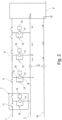
- Figure 2 shows in detail the operation state of the isolation switches 11 and the earth fault localization switch 13 of several separating devices 7 arranged along the bus 5.
- the measurement is carried out between the second and third separating device 7, while the other separating devices 7 are not involved. If the time allows, it is possible to sequentially measure the segments or sections of the second bus line 3 along the bus. This has the advantage, that the operation of the bus system is simple.
- Figure 3 shows a further preferred modification of the present invention, where in addition to the described localization of an earth fault along the second bus line 3,an earth fault localization along the first bus line 1 is implemented as well.
- the isolation switches 11 of all separating devices 7 are closed and a predefined constant current is applied from the central control unit 9 to one side of the first bus line 1, while the other end of the first bus line 1 is kept disconnected.
- the predefined constant current will flow through the first bus line 1 and the separating devices 7 to the earth fault location, and then through the short circuit of the earth fault into the earth wire and via the earth wire 19 back to the central control unit 9.
- the second bus line 3 is isolated on both sides of the central control unit 9.
- the earth fault localization switch 13 of one of the separating devices 7 will close, so as to establish a second conductive path, which extends from the voltage sensing unit 17 of one separating device 7 through the second bus line 3, the earth fault localization switch 13 of a neighbouring separating device 7 and the first bus line 1 back to the voltage sensing unit 17 of the one separating device 7 mentioned previously.
- the voltage drop between the connection point of the two separating devices 7 with the first bus line 1, respectively the terminals 21 and 23 can be measured using the four-wire sensing technique.
- the first bus line 1 can be measured sequentially and the measured voltages can either be evaluated by the controllers 15 of the individual separating devices 7 or can be transmitted to the central control unit 9, to be evaluated there.
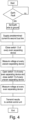
- Figure 4 is a flow chart explaining in detail again one earth fault localization procedure according to the present invention.
- the central control unit 9 monitors for earth faults, for example by applying a test signal to the second bus line 3 and by monitoring the earth wire 19 during the application of the test signal.
- the central control unit 9 switches into an earth fault localization procedure, in which case the earth wire is set to a fixed potential or grounded second wire 19 and a predefined constant current is applied to the second bus line 3 from one side of the central control unit 9, while the other end of the second bus line 3 is disconnected from the central control unit 9.
- the first bus line 1 is isolated on both sides of the central control unit 9.
- the earth fault localization switch 13 of one or several separating devices 7 is closed, so as to connect the first bus line 1 and the second bus line 3, while the earth fault localization switch 13 of at least one other separating device 7 is kept open, so as to disconnect the first bus line 1 and the second bus line 3.
- the voltage sensing unit 17 of the separating device 7 with the earth fault localization switch 13 in the disconnecting state will measure the voltage drop, which will be representative for the voltage drop along the second bus line 3 between the connecting point or terminal 25 of this separating device 7, having the earth fault localization switch 13 disconnecting the first bus line 1 and the second bus line 3, and the connection point or terminal 25b of a neighbouring separating device 7, having the earth fault localization switch 13 in the closed state.
- the voltage drop will be determined by the known predefined constant current I and the wire resistance of the segment or section of the second bus line 3 between the two terminals 25, which can be either known through an initial measurement of the fault free system or can be set based on empirical calculations in view of the length of the respective section or segment and the dimensions and material constants of the wire of the second bus line 3.
- the voltage drop of the segment or section of the second bus line 3, where the earth fault is located will be affected as well, a more precise localization will be possible.
- the voltage drop measured by the voltage sensing unit 17 monitoring the segment of section of the second bus line 3, where the earth fault occurs will depend on the actual position of the earth fault in the segment or section. The value will be higher for an earth fault close to the downstream side separating device 7 and lower for an earth fault close to the upstream side separating device 7.
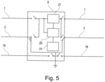
- the invention furthermore concerns the central control unit 9, which is implemented to cooperate with the separating devices 7 so as to enable the earth fault localization procedure of the invention and which is shown in more detail in Figure 5 .
- the central control unit 9 has to be configured so as to allow to connect the earth wire with ground or a fixed potential in respect to the first and second bus lines 1, 3. Additionally, the central control unit 9 has to be implemented so as to allow to apply a predefined constant current of a known value to at least one side of the second bus line and/or the first bus line. Alternatively, the constant current can be applied to the earth wire 19, in which case the earth wire 19 has to be disconnected on the other side of the central control unit 9. In this case it will be the first or second bus line 1, 3 which will be set to ground or a fixed potential.
- the central control unit 9 has to be able to digitally communicate with the separating devices 7 so as to instruct the opening and closing of the isolation switches 11 and the earth fault localization switches 13. Furthermore, the central control unit 9 has to be configured so as to receive the measurement result either in form of the measured value of the voltage or in form of a signal indicating the deviation of the measured voltage from a threshold value for a given segment or section of the second bus line 3.
- the central control unit 9 of this embodiment comprises a power source 27 for supplying power to either the first or the second bus line 1, 3.
- the power is supplied to the first bus line 1, whereas the second bus line 3 is grounded through respective switching means.
- the central control unit 9 further comprises a controller 31 which controls the respective operation conditions of the central control unit 9 and which can be configured to perform the comparison of the voltage measurement values obtain through the voltage sensing units 17 of the individual separating devices 7 with the respective threshold values.
- the central control unit 9 additionally comprises a communication means 29 for superimposing a modulated signal on the first or second bus line 1, 3 for transmitting and receiving digital coded information and commands.
- the central control unit is further equipped with switching means for connecting the earth wire 19 with ground.
- the present invention has been described in detail regarding a special embodiment, the present invention is not limited to this particular embodiment.
- the bus system with additional components like actuators, sensors and/or detectors.
- the bus 5 has been implemented as a two wired bus transmitting both, electrical power to operate the separating devices 7, actuators, sensors, and digital communication between the respective components of the bus systems.
- the invention is not limited to this configuration. It will be possible to monitor a simple power bus without digital data communication, and to implement a wireless data communication, for example.
- the separating devices 7 have been described so as to inform the central control unit 9 about the earth fault localization. This however is not essential for the present invention. Instead of that, it might be possible that an indication means is provided on each separating device 7, for example a LED, which will be activated if the respective separating device 7 is located on one of the both sides of the segment or section of the second bus line 3 where the earth fault has occurred. In this case, a maintenance worker has to walk along the building to inspect the separating devices 7 in order to find the earth fault localization.
- the voltage sensing unit 17 of the two separating devices 7 on both sides of the segment or section of the second bus line 3, where the earth fault has occurred will have measured the voltage drop on that segment or segment, it is possible to estimate the distance between each of the respective separating devices 7 and the earth fault by taking into account the wire resistance per meter of the second bus line 3. This allows even a more precise localization of the earth fault.
- a constant current I has been supplied to the second bus line 3 for the earth port localization.
- the earth fault localization can be performed for the first bus line 1, as described before, in the same manner.
- a predefined known current is applied from the central control unit 9 to one side of either the second bus line 3, the first bus line 1 or the earth wire 19.
- the central control unit can apply a predefined voltage and measure the resulting the current. Knowing the actual current and the actual voltage drop for a segment or section of the monitored bus line 1, 3 will allow the central control unit 9, to calculate the resistance of this segment or section and thus determine, where the earth fault is localized.
- an end of line module of the bus 5 has to be configured so as to disconnect the first and second bus lines 1, 3 for the earth fault localization procedure.
- the separating device 7, located closest to the end of line module can be used to disconnect the first and second bus lines 1, 3, by opening one the isolation switches 11.
- the first bus line 1 has been provided with the isolation switches 11, it is possible the have such switches arranged along the second bus line 3 as well, or to have the isolation switches arranged along the second bus line 3, only.
- bus lines 1, 3 were disconnected from the central control unit 9 during earth fault localisation procedure at one side of a respective loop, this disconnection does not necessarily be implemented in the central control unit 9, instead it can be the first and the last separating device 7, which will separate one bus line on both ends and the other bus line on one end.
Landscapes
- Locating Faults (AREA)
Description
- The present invention is directed to a separating device for a bus system, a central control unit for the bus system, a bus system comprising a plurality of separating devices and the central control unit as well as to a method for operating the bus system.
- Bus systems for transmitting power and signals between a central control unit and respective sensors and actuators are widely used in today technology. Examples of these bus systems include, without being limited to it, other detecting bus systems like fire detecting and alarming systems as well as butler detecting systems.
- In a bus system, to which the present invention is directed, in order to increase the reliability of the system, it is usual to provide a two wire bus arranged so as to form a loop and connecting in parallel the actuators and sensors between the two lines of the bus. Furthermore, usually the two bus lines are provided with an additional earth protection wire.
- In huge building complexes, like airports, plane stations, or congress centres, a plurality of these loops are provided, which might be connected to the same or a different central control unit, which in turn, might be connected to a master control unit.
- In order to increase the reliability of each loop, usually a plurality of separating devices are arranged along one wire of the loop. In case of a short circuit between the bus lines or in case of an earth fault, that is a short circuit between a bus line and the earth wire, it is possible to separate the section of the loop between two separating devices arranged at both sides of the error location, and to continue to use the system in a stub configuration.
- Such a system respectively such a separating device is disclosed for example in
WO2009/049949 A1 ,DE 10 2005 037 047 B3 orDE 10 2010 044 892 A1 . - While the detection of a short circuit between the two bus lines or between one of the bus lines and the earth wire as such is relatively easy by applying a control signal to the respective bus line and monitoring the voltage or current through the bus line, it is relatively difficult localize the error position.
- The above state of the art of
WO2009/049949 A1 describes to implement a voltage detector and a current detector in each separating device. In case of a short circuit or earth fault, the bus line is separated in a plurality of sections and each of separating devices monitors the integrity of a respective section of the bus lines including their own current detector respectively voltage detector. - However, since the separating devices are designed so as to separate only a first bus line into respective sections, it not possible to localize an earth fault at the second bus line within the system.
- It might be thought about the possibility to provide corresponding separating devices for the second bus line as well, as suggested in the above
DE 10 2005 037 047 B3 . However, in this case the whole arrangement will be complex and expensive, and the localizing of an earth fault will take a long time. -
DE 10 2010 044 892 A1 suggests to equip one or several separating devices with a switch connecting/disconnecting the first and second bus lines through a resistor. This switch and the resistor are used to operate the separating device as an end-of-line module in case the stub configuration of the bus has to be implemented. The separating device ofDE 10 2010 044 892 A1 does not include any voltage or current measurement devices. -
US 2014/159740 discloses a separating device arranged between a first and a second bus line of a bus for supplying electrical power, said separating device comprises a sensing unit arranged to measure a current and comprises a controller performing fault localisation procedure. -
US 6 292 541 discloses a separating device arranged between a first and a second bus line, said separating device comprises a sensing unit and a controller performing fault localisation procedure. - Accordingly, it is an objective of the present invention to provide a separating device, a central control unit, a bus system and a method for operating the bus system, which allow to localize an earth fault easier and more effectively.
- This object is achieved by a Separating device configured to be arranged between a first and a second bus line of a bus for supplying electrical power and/or for performing digital communication, said separating device comprising an earth fault localization switch arranged so as to allow to connect/disconnect a first and a second bus line of the bus to/from each other, a voltage sensing unit arrange so as to measure the voltage across the earth fault localization switch, and a controller configured so as to perform an earth fault localisation procedure, wherein the second bus line is supplied with a current, connect and disconnect the first bus line from the second bus line, and measure the voltage difference on both sides of the earth fault localization switch using the voltage sensing unit while the first and second bus lines are disconnected by the earth fault localization switch.
- It is further preferred that the controller of the separating device is configured to compare the voltage measurement result with a pre-stored threshold.
- It is furthermore preferred that the separating device is configured to transmit at least one of a voltage measurement result and a result of a comparison of the voltage measurement result and a pre-stored threshold to the central control unit.
- According to a further aspect of the invention there is provided a control unit for a bus system, said bus system comprising a first bus line, a second bus line, an earth wire, the central control unit and a plurality of separating devices as outlined above, wherein the central control unit is configured to connect the earth wire with ground or another know fixed potential, supply a current to the second bus line, instruct a first separating device to connect the first bus line and the second bus line through the earth fault localization switch, instruct a second separating device to disconnect the first and second bus line through the earth fault localization switch, so as to establish an electrical conductive path between both sides of a voltage sensing unit of said second separating device, said conductive path extending from the voltage sensing unit of said second separating device through the second bus line, the earth fault localization switch of the first separating device and the first bus line back to the voltage sensing unit of said second separating device, receive at least one of a voltage measurement result and a result of a comparison of the voltage measurement result and the threshold.
- It is furthermore preferred that the central control unit is configured to receive the voltage measurement result and to compare this voltage measurement result with a respective threshold value, assigned to said second separating device transmitting the voltage measurement result, respectively to the segment or section of the monitored bus line.
- According to the invention there is further provided a bus system comprising bus having a first bus line, a second bus line and an earth wire, a central control unit as described above and a plurality of separating devices as described above arranged along the first and second bus lines, wherein the central control unit is configured to control the separating devices by connecting/disconnecting at least one earth fault localisation switch.
- According to the invention there is further provided a method for localizing earth faults in the above bus system comprising the steps of setting the bus system in an earth fault localisation mode, connecting the earth wire with ground Furthermore, in a preferred embodiment the method further comprises, supplying a predefined current to the second bus line, connecting the first and second bus lines through the earth fault localization switch of a first separating device, while keeping the earth fault localization switch of a second separating device disconnecting the first and second bus lines so as to establish an electrical conductive path between both sides of a voltage sensing unit of said second separating device, said conductive path extending from the voltage sensing unit of said second separating device through the second bus line, the earth fault localization switch of the first separating device and the first bus line back to the voltage sensing unit of said second separating device, measuring the voltage by the voltage sensing unit of the second separating device so as to obtain a voltage measurement result, comparing the voltage measurement result with a threshold to localize an earth fault.
- Furthermore, in a preferred embodiment the method further comprises disconnecting the first and second bus lines through the earth fault localization switch of the first separating device and connecting the first and second bus lines through the earth fault localization switch of a second separating device, so as to establish a second electrical conductive path between both sides of a voltage sensing unit of said first separating device, said second conductive path extending from the voltage sensing unit of said first separating device, through the second bus line, the earth fault localization switch of the second separating device and the first bus line back to the voltage sensing unit of said first separating device, measuring the voltage by the voltage sensing unit of the first separating device so as to obtain a voltage measurement result, comparing the voltage measurement result with a threshold to localize an earth fault.
- Furthermore, in a preferred embodiment the method further comprises repeating connecting and disconnecting through the earth fault localization switches of the separating devices until voltage measurement values of all separating devices along the bus had been obtained.
- Furthermore, in a preferred embodiment the method further comprises detecting the presence of an earth fault by monitoring the current on the earth wire.
- In the following, detailed embodiments of the invention will be described with reference to the accompanying drawing.
- Figure 1
- shows a detailed view of a separating device according to the present invention;
- Figure 2
- shows a bus system comprising the separating device in case of an earth fault between the second bus line and the earth wire;
- Figure 3
- shows a view similar to
Figure 2 for the case of an earth fault between the first bus line and the earth wire; - Figure 4
- shows a first method for carrying out the earth fault localization according to the invention; and
- Figure 5
- shows a details of the central control unit.
- The separating device according to the present invention is shown in detail in
Figure 1 . - This separating device is configured to be connected with the first bus line. The separating device comprises a
first switch 11 which is arranged so as to be able to interrupt the first bus line. In the embodiment shown inFigure 1 , the separating device comprises a first andsecond terminal terminal 21 and theterminal 23 one or a plurality ofisolation switches 11 are provided. - Additionally, the
separating device 7 ofFigure 1 further comprises athird connection terminal 25 for connecting with the second bus line. - The separating device of
Figure 1 includes acontroller 15, which is configured to perform telecommunication through thebus lines central control unit 9, which is not shown inFigure 1 . - Furthermore, the
separating device 7 ofFigure 1 includes avoltage sensing unit 17, which can be part of thecontroller 15 and which is arranged so as to measure the voltage between the twobus lines terminals third terminal 25 on the other side. - Additionally, the
separating device 7 ofFigure 1 comprises and earthfault localization switch 13, which is arranged so as to allow to establish a conductive path between the point of equal potential A and thethird terminal 25, when closed, and which isolates the point of equal potential A and thethird terminal 25 when in an open state. - The
controller 15 is further configured to control the opening and closing operations of the isolation switch orswitches 11 and the earthfault localization switch 13. Furthermore, thecontroller 15 can be equipped with a storage unit for storing a measurement result of thevoltage sensing unit 17 and/or a threshold value, which can be used by thecontroller 15 to be compared with the voltage measurement result obtained from thevoltage sensing unit 17. - Although not shown, the separating
device 7 will usually be equipped with an energy storage unit, like a super cap or a rechargeable battery, so as to allow the operation of the separatingdevice 7 even in case of being disconnected from thebus lines separating device 7 is further equipped with corresponding switches allowing to separate this energy storage unit from thebus lines - In the following, the operation of the separating
device 7 will be described. - In normal operation, the
isolation switches 11 of theseparating device 7 will be in the closed state, so as to connect thefirst bus line 1 of the bus 5 so as to form a closed loop. Thisfirst bus line 1 will be used to supply power and signals for the digital communication to the separatingdevices 7. - The bus system will additionally be equipped with other detectors and other sensors or actuators, like flashing lights, loudspeakers and so on. These detectors, sensors and actuators can either be provided as dedicated devices along the bus 5 between the first and
second bus line separating device 7. - The detectors, sensors and actuators can either be of a kind which allows that the detector, sensor or actuator is addressed by the
central control unit 9, or can be a simple detector, like a smoke detector, which will only establish a conductive path between the first andsecond bus line - In the event that during the operation of the bus system over the time, a short circuit occurs between the
first bus line 1 and thesecond bus line 3, for example due to maintenance work or renovations of the building where the bus system is installed, theisolation switches 11 allow to disconnect a segment or section of thefirst bus line 1 between twoseparating devices 7, in which case the bus system can be operated in the form of two stub lines instead of a closed loop. - In the same manner, in case of a short circuit occurring between the
first bus line 1 and theearth wire 19, theisolation switches 11 can be used to isolate the segment or section of thebus line 1, where the short circuit has occurred, and the bus system can still continue to operate. There are several techniques to determine the segment or section of thefirst bus line 1 where such a short circuit has occurred, and accordingly, theseparating devices 7 on both sides of the damaged segment or section of thefirst bus line 1 can inform thecentral control unit 9 regarding the approximate location of the short circuit. - However, in case of an earth fault between the
second bus line 3 and theearth wire 19 it will not be possible neither to determine the location of the short circuit by means of theisolation switches 11, nor will it be possible to isolate the damaged segment or section. - However, such a short circuit between the
second bus line 3 and theearth wire 19 can cause serious problems especially regarding the digital communication between the separatingdevices 7, sensors, detectors, actuators and thecentral control unit 9 or betweenrespective separating devices 7. This problem becomes even more relevant in case of a huge system comprising severalcentral control units 9, which might be linked together by a several hierarchical bus systems and where usually all the earth wires are connected together. - In order to solve this problem, the present invention has established a procedure to localize an earth fault, that is a short circuit between the
second bus line 3 and theearth wire 19, in a reliable and fast manner. - On detection of such an earth fault, for example by monitoring the voltage or current on the
earth wire 19, while applying a test signal to thesecond bus line 3, the centralbus control unit 9 will switch into an earth fault localization procedure. - In this procedure, the
central control unit 9 will connect theearth wire 19 with ground or another known fixed potential relative to thesecond bus 3. Additionally, thefirst bus line 1 will be disconnected at both sides of the loop, and thesecond bus line 3 will be disconnected at one side of the loop. Furthermore, thecentral control unit 9 will apply a constant current to the connection point with thesecond bus line 3, so that this current flows from thecentral control unit 9 through thesecond bus line 3 and theseparating devices 7 provided between thecentral control unit 9 and the earth fault location, and then through the short circuit forming the earth fault into theearth wire 19 and back to thecentral control unit 9 via theearth wire 19. Furthermore, thecentral control unit 9 will inform theseparating devices 7 about the start of the earth fault localization procedure. - When the start of the earth fault localization procedure has been received by the
separating devices 7 at least one of theseparating devices 7 will close the earthfault localization switch 13 under the control of therespective controller 15 so as to establish a conductive part between thefirst bus line 1 and thesecond bus line 3 in theseparating device 7. - Furthermore, at least one of the isolation switches 11 of said
separation device 7 will remain in a closed state as well. - A neighbouring
separating device 7 will maintain the earthfault localization switch 13 in an open state so as to disconnect thefirst bus line 1 and thesecond bus line 3, and will keep at least oneisolation switch 11 closed so that an electrical conductive path is established, which extends from thevoltage sensing unit 17 of the oneseparating device 7 through thesecond bus lines 3, the earthfault localization switch 13 of theneighbouring separating device 7 and thefirst bus line 1 with the isolation switches 11 in the closed state back to thevoltage sensing unit 17 of the first mentioned separatingdevice 7. In this manner, a four-wire sensing respectively a four-point measurement method is established for measuring the voltage drop of the segment or section of thesecond bus line 3 between the connection points of both separatingdevices 7, i.e. theterminals 25 of the twoneighbouring separating devices 7. - If the two
separating devices 7 performing this procedure are located between the centralbus control unit 9 and the earth fault location, when viewed from the side where thesecond bus line 3 remains connected, there will be a detectable voltage drop due to the wire resistance and the predefined constant current flowing through thesecond bus line 3 and theearth wire 19. - On the other hand, if the two
separating devices 7 are not located between the earth fault location and thecentral control unit 9, when viewed from the side where thesecond bus line 3 remains connected, there will be no current flowing through the respective segment or section of thesecond bus line 3 and accordingly, thevoltage sensing unit 17 will not sense any voltage drop. - If the earth fault occurs between the two
separating devices 7, the voltage drop measured by thevoltage sensing unit 17 will differ from the case, that no earth fault is present. - Thus, by measuring the voltage drop of all segments of the
second bus line 3 between the separatingdevices 7 along the bus 5, it is possible to determine the location of the earth fault. - To increase the accuracy of the measurement, it is advantageous that the
central control unit 9 applies the constant current subsequently from the other side of thesecond bus line 3 and to repeat the localization determination. - Furthermore, the accuracy of the measurement can be improved further by measuring a segment or section of the second bus line once using the
voltage sensing unit 17 of an upstreamside separating device 7, that is a separating device closer to the current applying side of thecentral control unit 9, and subsequently by thevoltage sensing unit 17 of adownstream separating device 7. - In order to accelerate the localization of the earth fault, it is advantageous to open for example the upstream
side isolation switch 11 of everyuneven separating device 7 and to open thedownstream isolation switch 11 of every even separatingdevice 7 while keeping the other isolation switches 11 closed. In this way, the segment or section between the first and second, the third and fourth, the fifth and sixth and so on separatingdevice 7 can be monitored for localizing an earth fault. Subsequently the downstream side isolation switches 11 of theuneven separating devices 7 will be opened and the upstream side isolation switches of the even separatingdevices 7 will be opened as well. The other isolation switches 11 will be closed. Then, it is possible to monitor the segments or sections between the second and third, fourth and fifth, sixth and seventh and so on separatingdevice 7, so that the entiresecond bus line 3 can be checked for an earth fault localization in a short time. - In an advantageous modification of the present invention the
controller 15 of each separatingdevice 7 will compare the result of the measurement by thevoltage sensing unit 17 with a threshold value, which can either be a fixed value set in advance, or can be a value which is obtained during an initialization procedure for the fault free system and stored in a corresponding storage unit. Depending on the result of the comparison thecontroller 15 will transmit an information signal informing about the localization of the earth fault in a segment or section of thesecond bus line 3 adjacent to therespective separating device 7. - In a further advantageous modification the
controller 15 will obtain the voltage measurement from thevoltage sensing unit 17, will convert this value into a digital signal and will transmit the digital signal to thecentral control unit 9, where the value is compared with a threshold value which might be obtained in the same manner as described above, either by setting a fixed value in advance or by obtaining a threshold value for the fault free system during initialization. -
Figure 2 shows in detail the operation state of the isolation switches 11 and the earthfault localization switch 13 ofseveral separating devices 7 arranged along the bus 5. Here, the measurement is carried out between the second andthird separating device 7, while theother separating devices 7 are not involved. If the time allows, it is possible to sequentially measure the segments or sections of thesecond bus line 3 along the bus. This has the advantage, that the operation of the bus system is simple. -
Figure 3 shows a further preferred modification of the present invention, where in addition to the described localization of an earth fault along thesecond bus line 3,an earth fault localization along thefirst bus line 1 is implemented as well. In order to detect such an earth fault along thefirst bus line 1, that is a short circuit between thefirst bus line 1 and theearth wire 19, the isolation switches 11 of all separatingdevices 7 are closed and a predefined constant current is applied from thecentral control unit 9 to one side of thefirst bus line 1, while the other end of thefirst bus line 1 is kept disconnected. - In this case the predefined constant current will flow through the
first bus line 1 and theseparating devices 7 to the earth fault location, and then through the short circuit of the earth fault into the earth wire and via theearth wire 19 back to thecentral control unit 9. - The
second bus line 3 is isolated on both sides of thecentral control unit 9. The earthfault localization switch 13 of one of theseparating devices 7 will close, so as to establish a second conductive path, which extends from thevoltage sensing unit 17 of oneseparating device 7 through thesecond bus line 3, the earthfault localization switch 13 of aneighbouring separating device 7 and thefirst bus line 1 back to thevoltage sensing unit 17 of the oneseparating device 7 mentioned previously. Again, the voltage drop between the connection point of the twoseparating devices 7 with thefirst bus line 1, respectively theterminals second bus line 3, thefirst bus line 1 can be measured sequentially and the measured voltages can either be evaluated by thecontrollers 15 of theindividual separating devices 7 or can be transmitted to thecentral control unit 9, to be evaluated there. -
Figure 4 is a flow chart explaining in detail again one earth fault localization procedure according to the present invention. - The
central control unit 9 monitors for earth faults, for example by applying a test signal to thesecond bus line 3 and by monitoring theearth wire 19 during the application of the test signal. - In case that an earth fault is detected, the
central control unit 9 switches into an earth fault localization procedure, in which case the earth wire is set to a fixed potential or groundedsecond wire 19 and a predefined constant current is applied to thesecond bus line 3 from one side of thecentral control unit 9, while the other end of thesecond bus line 3 is disconnected from thecentral control unit 9. Thefirst bus line 1 is isolated on both sides of thecentral control unit 9. Subsequently the earthfault localization switch 13 of one orseveral separating devices 7 is closed, so as to connect thefirst bus line 1 and thesecond bus line 3, while the earthfault localization switch 13 of at least oneother separating device 7 is kept open, so as to disconnect thefirst bus line 1 and thesecond bus line 3. - The
voltage sensing unit 17 of theseparating device 7 with the earthfault localization switch 13 in the disconnecting state will measure the voltage drop, which will be representative for the voltage drop along thesecond bus line 3 between the connecting point or terminal 25 of thisseparating device 7, having the earthfault localization switch 13 disconnecting thefirst bus line 1 and thesecond bus line 3, and the connection point or terminal 25b of aneighbouring separating device 7, having the earthfault localization switch 13 in the closed state. The voltage drop will be determined by the known predefined constant current I and the wire resistance of the segment or section of thesecond bus line 3 between the twoterminals 25, which can be either known through an initial measurement of the fault free system or can be set based on empirical calculations in view of the length of the respective section or segment and the dimensions and material constants of the wire of thesecond bus line 3. - For the event that an earth fault has occurred between the segment or section of the
second bus line 3 presently monitored and thecentral control unit 9 due to the grounding of theearth wire 19 only a reduced current will flow through this segment or section of thesecond bus line 3, and accordingly, the voltage drop will be smaller than expected. This measurement therefore allows to localize the earth fault. Subsequently the procedure moves to monitor another segment or section of thesecond bus line 3 by opening the earthfault localization switch 13, which had been closed before and by closing another earthfault localization switch 13 of aseparating device 7. - For those separating
devices 7 located between thecentral control unit 9 and the earth fault localisation, when viewed from the side where thecentral control unit 9 is connected to thesecond bus line 3, the voltage drop will be as expected, since the entire predefined current will flow through the respective segments or sections of thesecond bus line 3. For those separatingdevice 7 located at the other side of the earth fault location, when viewed from the side where thecentral control unit 9 is connected to thesecond bus line 3, there will be no current flowing through the respective segment or section of thesecond bus line 3 and therefore the measured voltage value will depart from the expected value, so that the earth fault can be localized. - Additionally, since the voltage drop of the segment or section of the
second bus line 3, where the earth fault is located will be affected as well, a more precise localization will be possible. The voltage drop measured by thevoltage sensing unit 17 monitoring the segment of section of thesecond bus line 3, where the earth fault occurs, will depend on the actual position of the earth fault in the segment or section. The value will be higher for an earth fault close to the downstreamside separating device 7 and lower for an earth fault close to the upstreamside separating device 7. - The invention furthermore concerns the
central control unit 9, which is implemented to cooperate with theseparating devices 7 so as to enable the earth fault localization procedure of the invention and which is shown in more detail inFigure 5 . Thecentral control unit 9 has to be configured so as to allow to connect the earth wire with ground or a fixed potential in respect to the first andsecond bus lines central control unit 9 has to be implemented so as to allow to apply a predefined constant current of a known value to at least one side of the second bus line and/or the first bus line. Alternatively, the constant current can be applied to theearth wire 19, in which case theearth wire 19 has to be disconnected on the other side of thecentral control unit 9. In this case it will be the first orsecond bus line - Furthermore, the
central control unit 9 has to be able to digitally communicate with theseparating devices 7 so as to instruct the opening and closing of the isolation switches 11 and the earth fault localization switches 13. Furthermore, thecentral control unit 9 has to be configured so as to receive the measurement result either in form of the measured value of the voltage or in form of a signal indicating the deviation of the measured voltage from a threshold value for a given segment or section of thesecond bus line 3. - As shown in
Figure 5 , thecentral control unit 9 of this embodiment comprises apower source 27 for supplying power to either the first or thesecond bus line first bus line 1, whereas thesecond bus line 3 is grounded through respective switching means. - The
central control unit 9 further comprises acontroller 31 which controls the respective operation conditions of thecentral control unit 9 and which can be configured to perform the comparison of the voltage measurement values obtain through thevoltage sensing units 17 of theindividual separating devices 7 with the respective threshold values. - The
central control unit 9 additionally comprises a communication means 29 for superimposing a modulated signal on the first orsecond bus line - As shown in
Figure 5 , the central control unit is further equipped with switching means for connecting theearth wire 19 with ground. - Although the present invention has been described in detail regarding a special embodiment, the present invention is not limited to this particular embodiment. For example, it will be possible to provide the bus system with additional components like actuators, sensors and/or detectors. Furthermore, in the present invention, the bus 5 has been implemented as a two wired bus transmitting both, electrical power to operate the
separating devices 7, actuators, sensors, and digital communication between the respective components of the bus systems. However, the invention is not limited to this configuration. It will be possible to monitor a simple power bus without digital data communication, and to implement a wireless data communication, for example. - Furthermore, in the present embodiment, the
separating devices 7 have been described so as to inform thecentral control unit 9 about the earth fault localization. This however is not essential for the present invention. Instead of that, it might be possible that an indication means is provided on each separatingdevice 7, for example a LED, which will be activated if therespective separating device 7 is located on one of the both sides of the segment or section of thesecond bus line 3 where the earth fault has occurred. In this case, a maintenance worker has to walk along the building to inspect theseparating devices 7 in order to find the earth fault localization. - Furthermore, since the
voltage sensing unit 17 of the twoseparating devices 7 on both sides of the segment or section of thesecond bus line 3, where the earth fault has occurred, will have measured the voltage drop on that segment or segment, it is possible to estimate the distance between each of therespective separating devices 7 and the earth fault by taking into account the wire resistance per meter of thesecond bus line 3. This allows even a more precise localization of the earth fault. - In the embodiment described above, a constant current I has been supplied to the
second bus line 3 for the earth port localization. However, it is possible to apply an alternating current of a known amplitude to thesecond wire 3 instead. - In stead of the
second bus line 3, the earth fault localization can be performed for thefirst bus line 1, as described before, in the same manner. - In the preferred embodiments a predefined known current is applied from the
central control unit 9 to one side of either thesecond bus line 3, thefirst bus line 1 or theearth wire 19. However, as an alternative the central control unit can apply a predefined voltage and measure the resulting the current. Knowing the actual current and the actual voltage drop for a segment or section of the monitoredbus line central control unit 9, to calculate the resistance of this segment or section and thus determine, where the earth fault is localized. - In case of applying the present invention to a stub bus 5, an end of line module of the bus 5 has to be configured so as to disconnect the first and
second bus lines - However, in case of using a resistor or a diode as end of line module, the
separating device 7, located closest to the end of line module can be used to disconnect the first andsecond bus lines - Whereas in the above description the
first bus line 1 has been provided with the isolation switches 11, it is possible the have such switches arranged along thesecond bus line 3 as well, or to have the isolation switches arranged along thesecond bus line 3, only. - While in the above embodiment the
bus lines central control unit 9 during earth fault localisation procedure at one side of a respective loop, this disconnection does not necessarily be implemented in thecentral control unit 9, instead it can be the first and thelast separating device 7, which will separate one bus line on both ends and the other bus line on one end.
Claims (10)
- Separating device configured to be arranged between a first and a second bus line (1, 3) of a bus (5) for supplying electrical power and/or for performing digital communication, said separating device (7) comprising:an earth fault localization switch (13) arranged so as to allow to connect/disconnect a first and a second bus line (1, 3) of the bus (5) to/from each other;a voltage sensing unit (17) arrange so as to measure the voltage across the earth fault localization switch (13); anda controller (15) configured so as to:perform an earth fault localisation procedure, wherein the second bus line (3) is being supplied with a current;connect and disconnect the first bus line (1) from the second bus line (3), andmeasure the voltage difference on both sides of the earth fault localization switch (13) using the voltage sensing unit (17) while the first and second bus lines (1, 3) are disconnected by the earth fault localization switch (13).
- Separating device according to claim 1, wherein the controller (15) of the separating device (7) is configured to compare the voltage measurement result with a pre-stored threshold.
- Separating device according to claim 1 or 2, wherein
the separating device (7) is configured to transmit at least one of a voltage measurement result and a result of a comparison of the voltage measurement result and a pre-stored threshold to a central control unit (9). - A central control unit for a bus system, said bus system comprising a first bus line (1), a second bus line (3), an earth wire (19), the central control unit (9) and a plurality of separating devices (7) according to any of claims 1 to 3 arranged along the first and second bus lines (1, 3), whereinthe central control unit (9) is configured toconnect the earth wire (19) at least one of ground and a fixed potential; andsupply a current to the second bus line (3),instruct a first separating device (7) to connect the first bus line (1) and the second bus line (3) through the earth fault localization switch (13);instruct a second separating device (7) to disconnect the first and second bus line (1, 3) through the earth fault localization switch (13), so as to establish an electrical conductive path between both sides of a voltage sensing unit (17) of said second separating device (7), said conductive path extending from the voltage sensing unit (17) of said second separating device (7) through the second bus line (3), the earth fault localization switch (13) of the first separating device (7) and the first bus line (1) back to the voltage sensing unit (17) of said second separating device (7),receive at least one of a voltage measurement result and a result of a comparison of the voltage measurement result and the threshold.
- A central control unit according to claim 4, wherein the central control unit (9) is configured to receive the voltage measurement result and to compare this voltage measurement result with a respective threshold value, assigned to said second separating device (7) transmitting the voltage measurement result.
- A bus system comprising bus (5) having a first bus line (1), a second bus line (3) and an earth wire (19), a central control unit (9) according to any of claims 4 and 5 and a plurality of separating devices (7) according to any of claims 1 to 3 arranged along the first and second bus lines (1, 3), wherein
the central control unit (9) is configured to control the separating devices (7) by connecting/disconnecting at least one earth fault localisation switch (13). - A method for localizing an earth fault in a bus system according to claim 6, the method comprising the steps ofsetting the bus system in an earth fault localisation mode,connecting the earth wire (19) with ground or a fixed potential,supplying a current to the second bus line (3),connecting the first and second bus lines (1, 3) through the earth fault localization switch (13) of a first separating device (7), while keeping the earth fault localization switch (13) of a second separating device (7) disconnecting the first and second bus lines (1, 3) so as to establish an electrical conductive path between both sides of a voltage sensing unit (17) of said second separating device (7), said conductive path extending from the voltage sensing unit (17) of said second separating device (7) through the second bus line (3), the earth fault localization switch (13) of the first separating device (7) and the first bus line (1) back to the voltage sensing unit (17) of said second separating device (7),measuring the voltage by the voltage sensing unit (17) of the second separating device (7) so as to obtain a voltage measurement result,comparing the voltage measurement result with a threshold to localize an earth fault.
- The method of claim 7, further comprisingdisconnecting the first and second bus lines (1, 3) through the earth fault localization switch (13) of the first separating device (7) and connecting the first and second bus lines (1, 3) through the earth fault localization switch (13) of a second separating device (7), so as to establish a second electrical conductive path between both sides of a voltage sensing unit (17) of said first separating device (7), said second conductive path extending from the voltage sensing unit (17) of said first separating device (7), through the second bus line (3), the earth fault localization switch (13) of the second separating device (7) and the first bus line (1) back to the voltage sensing unit (17) of said first separating device (7),measuring the voltage by the voltage sensing unit (17) of the first separating device (7) so as to obtain a voltage measurement result,comparing the voltage measurement result with a threshold to localize an earth fault.
- The method of claim 7 or 8, further comprising
repeating connecting and disconnecting through the earth fault localization switches (13) of the separating devices (7) until voltage measurement values of all separating devices (7) along the bus (5) have been obtained. - The method of claims 7 to 9, further comprising
detecting the presence of an earth fault by monitoring the current on the earth wire (19).
Priority Applications (1)
| Application Number | Priority Date | Filing Date | Title |
|---|---|---|---|
| EP19182682.5A EP3758179B1 (en) | 2019-06-26 | 2019-06-26 | Separating device for a bus system, central control unit for the bus system, bus system and method for operating the bus system |
Applications Claiming Priority (1)
| Application Number | Priority Date | Filing Date | Title |
|---|---|---|---|
| EP19182682.5A EP3758179B1 (en) | 2019-06-26 | 2019-06-26 | Separating device for a bus system, central control unit for the bus system, bus system and method for operating the bus system |
Publications (2)
| Publication Number | Publication Date |
|---|---|
| EP3758179A1 EP3758179A1 (en) | 2020-12-30 |
| EP3758179B1 true EP3758179B1 (en) | 2023-11-29 |
Family
ID=67105764
Family Applications (1)
| Application Number | Title | Priority Date | Filing Date |
|---|---|---|---|
| EP19182682.5A Active EP3758179B1 (en) | 2019-06-26 | 2019-06-26 | Separating device for a bus system, central control unit for the bus system, bus system and method for operating the bus system |
Country Status (1)
| Country | Link |
|---|---|
| EP (1) | EP3758179B1 (en) |
Family Cites Families (5)
| Publication number | Priority date | Publication date | Assignee | Title |
|---|---|---|---|---|
| US6292541B1 (en) * | 1998-11-10 | 2001-09-18 | Pittway Corporation | Line shunt and ground fault apparatus method |
| DE102005037047B3 (en) | 2005-08-05 | 2006-12-28 | Novar Gmbh | Building control and hazard alert system, has bus substation circuit lying between parallely connected direct current connections of bridges and measuring voltage ratios and their polarity at alternating voltage inputs of bridges |
| EP2051220A1 (en) | 2007-10-17 | 2009-04-22 | Siemens Building Technologies Fire & Security Products GmbH & Co. oHG | Separating device with energy storage for an electric circuit conducting energy |
| DE102010044892A1 (en) | 2010-09-09 | 2012-03-15 | Novar Gmbh | Danger alarm system with two data transmission speeds |
| BR112014001356B1 (en) * | 2011-07-21 | 2020-10-20 | Siemens Aktiengesellschaft | method and device for determining a failed section of a power supply line |
-
2019
- 2019-06-26 EP EP19182682.5A patent/EP3758179B1/en active Active
Also Published As
| Publication number | Publication date |
|---|---|
| EP3758179A1 (en) | 2020-12-30 |
Similar Documents
| Publication | Publication Date | Title |
|---|---|---|
| US10126345B2 (en) | Device and method for insulation monitoring in a power supply system including a high-resistance grounded neutral point | |
| KR100883777B1 (en) | How to generate fault indication of terminal equipment in distribution automation system | |
| CN101738569B (en) | Device for detecting anomalies in installation for rail vehicle supervision, associated installation and method | |
| US10784674B2 (en) | Methods and devices for selective insulation monitoring in underground IT power supply systems | |
| EP3699619B1 (en) | Wiring-integrity automatic monitoring system having improved features | |
| US20170067953A1 (en) | Method and device for insulation fault location having an adaptive test current determination | |
| EP2961919B1 (en) | Subsea electrical unit and system | |
| CA2996292A1 (en) | System and method for automatic high resistance ground pulse activation and detection | |
| US20060017445A1 (en) | Electrical supply network | |
| EP2576407A1 (en) | Switch detection system | |
| KR101205048B1 (en) | Electric protection monitoring system | |
| KR102597249B1 (en) | Monitoring system and method for detecting connection error of remote terminal unit | |
| CN113078620B (en) | Electrical distribution systems and methods of monitoring zone-selective interlocking in electrical distribution systems | |
| US9989576B2 (en) | Two-wire resistance terminated ground check | |
| CN106841897A (en) | A kind of electric vehicle high-tension apparatus connection detection circuit | |
| EP3758179A1 (en) | Separating device for a bus system, central control unit for the bus system, bus system and method for operating the bus system | |
| KR102049425B1 (en) | Method and apparatus for checking normal operation of arc detecting in power system | |
| KR100777209B1 (en) | Automatic separation system of fault section for data collection and wiring circuit | |
| EP3270174B1 (en) | Test arrangement | |
| KR102368925B1 (en) | Intelligent streetlight distribution network monitoring method using safety voltage and Intelligent streetlight distribution network monitoring system using safety voltage | |
| KR100775025B1 (en) | A automatic separating method and system of fault locating for distribution line | |
| KR200342561Y1 (en) | Pipeline leak detection apparatus for measuring the insulation resistance bidirectionally | |
| KR101693434B1 (en) | Apparatus and method for detecting error of substation | |
| EP4339625B1 (en) | Improvements in or relating to sensors for use in hvdc power transmission networks | |
| CN114966302A (en) | Fault location system |
Legal Events
| Date | Code | Title | Description |
|---|---|---|---|
| PUAI | Public reference made under article 153(3) epc to a published international application that has entered the european phase |
Free format text: ORIGINAL CODE: 0009012 |
|
| STAA | Information on the status of an ep patent application or granted ep patent |
Free format text: STATUS: THE APPLICATION HAS BEEN PUBLISHED |
|
| AK | Designated contracting states |
Kind code of ref document: A1 Designated state(s): AL AT BE BG CH CY CZ DE DK EE ES FI FR GB GR HR HU IE IS IT LI LT LU LV MC MK MT NL NO PL PT RO RS SE SI SK SM TR |
|
| AX | Request for extension of the european patent |
Extension state: BA ME |
|
| STAA | Information on the status of an ep patent application or granted ep patent |
Free format text: STATUS: REQUEST FOR EXAMINATION WAS MADE |
|
| 17P | Request for examination filed |
Effective date: 20210630 |
|
| RBV | Designated contracting states (corrected) |
Designated state(s): AL AT BE BG CH CY CZ DE DK EE ES FI FR GB GR HR HU IE IS IT LI LT LU LV MC MK MT NL NO PL PT RO RS SE SI SK SM TR |
|
| RIC1 | Information provided on ipc code assigned before grant |
Ipc: H02H 7/26 20060101ALI20230509BHEP Ipc: H02H 3/16 20060101ALI20230509BHEP Ipc: G08B 29/06 20060101ALI20230509BHEP Ipc: G08B 25/04 20060101ALI20230509BHEP Ipc: H02H 3/04 20060101AFI20230509BHEP |
|
| GRAP | Despatch of communication of intention to grant a patent |
Free format text: ORIGINAL CODE: EPIDOSNIGR1 |
|
| STAA | Information on the status of an ep patent application or granted ep patent |
Free format text: STATUS: GRANT OF PATENT IS INTENDED |
|
| P01 | Opt-out of the competence of the unified patent court (upc) registered |
Effective date: 20230523 |
|
| INTG | Intention to grant announced |
Effective date: 20230616 |
|
| GRAS | Grant fee paid |
Free format text: ORIGINAL CODE: EPIDOSNIGR3 |
|
| GRAA | (expected) grant |
Free format text: ORIGINAL CODE: 0009210 |
|
| STAA | Information on the status of an ep patent application or granted ep patent |
Free format text: STATUS: THE PATENT HAS BEEN GRANTED |
|
| AK | Designated contracting states |
Kind code of ref document: B1 Designated state(s): AL AT BE BG CH CY CZ DE DK EE ES FI FR GB GR HR HU IE IS IT LI LT LU LV MC MK MT NL NO PL PT RO RS SE SI SK SM TR |
|
| REG | Reference to a national code |
Ref country code: GB Ref legal event code: FG4D |
|
| REG | Reference to a national code |
Ref country code: CH Ref legal event code: EP |
|
| REG | Reference to a national code |
Ref country code: DE Ref legal event code: R096 Ref document number: 602019042217 Country of ref document: DE |
|
| REG | Reference to a national code |
Ref country code: IE Ref legal event code: FG4D |
|
| REG | Reference to a national code |
Ref country code: LT Ref legal event code: MG9D |
|
| REG | Reference to a national code |
Ref country code: NL Ref legal event code: MP Effective date: 20231129 |
|
| PG25 | Lapsed in a contracting state [announced via postgrant information from national office to epo] |
Ref country code: GR Free format text: LAPSE BECAUSE OF FAILURE TO SUBMIT A TRANSLATION OF THE DESCRIPTION OR TO PAY THE FEE WITHIN THE PRESCRIBED TIME-LIMIT Effective date: 20240301 |
|
| PG25 | Lapsed in a contracting state [announced via postgrant information from national office to epo] |
Ref country code: IS Free format text: LAPSE BECAUSE OF FAILURE TO SUBMIT A TRANSLATION OF THE DESCRIPTION OR TO PAY THE FEE WITHIN THE PRESCRIBED TIME-LIMIT Effective date: 20240329 |
|
| PG25 | Lapsed in a contracting state [announced via postgrant information from national office to epo] |
Ref country code: LT Free format text: LAPSE BECAUSE OF FAILURE TO SUBMIT A TRANSLATION OF THE DESCRIPTION OR TO PAY THE FEE WITHIN THE PRESCRIBED TIME-LIMIT Effective date: 20231129 |
|
| PG25 | Lapsed in a contracting state [announced via postgrant information from national office to epo] |
Ref country code: ES Free format text: LAPSE BECAUSE OF FAILURE TO SUBMIT A TRANSLATION OF THE DESCRIPTION OR TO PAY THE FEE WITHIN THE PRESCRIBED TIME-LIMIT Effective date: 20231129 |
|
| PG25 | Lapsed in a contracting state [announced via postgrant information from national office to epo] |
Ref country code: LT Free format text: LAPSE BECAUSE OF FAILURE TO SUBMIT A TRANSLATION OF THE DESCRIPTION OR TO PAY THE FEE WITHIN THE PRESCRIBED TIME-LIMIT Effective date: 20231129 Ref country code: IS Free format text: LAPSE BECAUSE OF FAILURE TO SUBMIT A TRANSLATION OF THE DESCRIPTION OR TO PAY THE FEE WITHIN THE PRESCRIBED TIME-LIMIT Effective date: 20240329 Ref country code: GR Free format text: LAPSE BECAUSE OF FAILURE TO SUBMIT A TRANSLATION OF THE DESCRIPTION OR TO PAY THE FEE WITHIN THE PRESCRIBED TIME-LIMIT Effective date: 20240301 Ref country code: ES Free format text: LAPSE BECAUSE OF FAILURE TO SUBMIT A TRANSLATION OF THE DESCRIPTION OR TO PAY THE FEE WITHIN THE PRESCRIBED TIME-LIMIT Effective date: 20231129 Ref country code: BG Free format text: LAPSE BECAUSE OF FAILURE TO SUBMIT A TRANSLATION OF THE DESCRIPTION OR TO PAY THE FEE WITHIN THE PRESCRIBED TIME-LIMIT Effective date: 20240229 |
|
| REG | Reference to a national code |
Ref country code: AT Ref legal event code: MK05 Ref document number: 1637105 Country of ref document: AT Kind code of ref document: T Effective date: 20231129 |
|
| PG25 | Lapsed in a contracting state [announced via postgrant information from national office to epo] |
Ref country code: NL Free format text: LAPSE BECAUSE OF FAILURE TO SUBMIT A TRANSLATION OF THE DESCRIPTION OR TO PAY THE FEE WITHIN THE PRESCRIBED TIME-LIMIT Effective date: 20231129 |
|
| PG25 | Lapsed in a contracting state [announced via postgrant information from national office to epo] |
Ref country code: SE Free format text: LAPSE BECAUSE OF FAILURE TO SUBMIT A TRANSLATION OF THE DESCRIPTION OR TO PAY THE FEE WITHIN THE PRESCRIBED TIME-LIMIT Effective date: 20231129 Ref country code: RS Free format text: LAPSE BECAUSE OF FAILURE TO SUBMIT A TRANSLATION OF THE DESCRIPTION OR TO PAY THE FEE WITHIN THE PRESCRIBED TIME-LIMIT Effective date: 20231129 Ref country code: PL Free format text: LAPSE BECAUSE OF FAILURE TO SUBMIT A TRANSLATION OF THE DESCRIPTION OR TO PAY THE FEE WITHIN THE PRESCRIBED TIME-LIMIT Effective date: 20231129 Ref country code: NO Free format text: LAPSE BECAUSE OF FAILURE TO SUBMIT A TRANSLATION OF THE DESCRIPTION OR TO PAY THE FEE WITHIN THE PRESCRIBED TIME-LIMIT Effective date: 20240229 Ref country code: NL Free format text: LAPSE BECAUSE OF FAILURE TO SUBMIT A TRANSLATION OF THE DESCRIPTION OR TO PAY THE FEE WITHIN THE PRESCRIBED TIME-LIMIT Effective date: 20231129 Ref country code: LV Free format text: LAPSE BECAUSE OF FAILURE TO SUBMIT A TRANSLATION OF THE DESCRIPTION OR TO PAY THE FEE WITHIN THE PRESCRIBED TIME-LIMIT Effective date: 20231129 Ref country code: HR Free format text: LAPSE BECAUSE OF FAILURE TO SUBMIT A TRANSLATION OF THE DESCRIPTION OR TO PAY THE FEE WITHIN THE PRESCRIBED TIME-LIMIT Effective date: 20231129 |
|
| PG25 | Lapsed in a contracting state [announced via postgrant information from national office to epo] |
Ref country code: DK Free format text: LAPSE BECAUSE OF FAILURE TO SUBMIT A TRANSLATION OF THE DESCRIPTION OR TO PAY THE FEE WITHIN THE PRESCRIBED TIME-LIMIT Effective date: 20231129 |
|
| PG25 | Lapsed in a contracting state [announced via postgrant information from national office to epo] |
Ref country code: AT Free format text: LAPSE BECAUSE OF FAILURE TO SUBMIT A TRANSLATION OF THE DESCRIPTION OR TO PAY THE FEE WITHIN THE PRESCRIBED TIME-LIMIT Effective date: 20231129 Ref country code: CZ Free format text: LAPSE BECAUSE OF FAILURE TO SUBMIT A TRANSLATION OF THE DESCRIPTION OR TO PAY THE FEE WITHIN THE PRESCRIBED TIME-LIMIT Effective date: 20231129 |
|
| PG25 | Lapsed in a contracting state [announced via postgrant information from national office to epo] |
Ref country code: SK Free format text: LAPSE BECAUSE OF FAILURE TO SUBMIT A TRANSLATION OF THE DESCRIPTION OR TO PAY THE FEE WITHIN THE PRESCRIBED TIME-LIMIT Effective date: 20231129 |
|
| PG25 | Lapsed in a contracting state [announced via postgrant information from national office to epo] |
Ref country code: SM Free format text: LAPSE BECAUSE OF FAILURE TO SUBMIT A TRANSLATION OF THE DESCRIPTION OR TO PAY THE FEE WITHIN THE PRESCRIBED TIME-LIMIT Effective date: 20231129 Ref country code: SK Free format text: LAPSE BECAUSE OF FAILURE TO SUBMIT A TRANSLATION OF THE DESCRIPTION OR TO PAY THE FEE WITHIN THE PRESCRIBED TIME-LIMIT Effective date: 20231129 Ref country code: RO Free format text: LAPSE BECAUSE OF FAILURE TO SUBMIT A TRANSLATION OF THE DESCRIPTION OR TO PAY THE FEE WITHIN THE PRESCRIBED TIME-LIMIT Effective date: 20231129 Ref country code: IT Free format text: LAPSE BECAUSE OF FAILURE TO SUBMIT A TRANSLATION OF THE DESCRIPTION OR TO PAY THE FEE WITHIN THE PRESCRIBED TIME-LIMIT Effective date: 20231129 Ref country code: EE Free format text: LAPSE BECAUSE OF FAILURE TO SUBMIT A TRANSLATION OF THE DESCRIPTION OR TO PAY THE FEE WITHIN THE PRESCRIBED TIME-LIMIT Effective date: 20231129 Ref country code: DK Free format text: LAPSE BECAUSE OF FAILURE TO SUBMIT A TRANSLATION OF THE DESCRIPTION OR TO PAY THE FEE WITHIN THE PRESCRIBED TIME-LIMIT Effective date: 20231129 Ref country code: CZ Free format text: LAPSE BECAUSE OF FAILURE TO SUBMIT A TRANSLATION OF THE DESCRIPTION OR TO PAY THE FEE WITHIN THE PRESCRIBED TIME-LIMIT Effective date: 20231129 Ref country code: AT Free format text: LAPSE BECAUSE OF FAILURE TO SUBMIT A TRANSLATION OF THE DESCRIPTION OR TO PAY THE FEE WITHIN THE PRESCRIBED TIME-LIMIT Effective date: 20231129 |
|
| PG25 | Lapsed in a contracting state [announced via postgrant information from national office to epo] |
Ref country code: PT Free format text: LAPSE BECAUSE OF FAILURE TO SUBMIT A TRANSLATION OF THE DESCRIPTION OR TO PAY THE FEE WITHIN THE PRESCRIBED TIME-LIMIT Effective date: 20240401 |
|
| PG25 | Lapsed in a contracting state [announced via postgrant information from national office to epo] |
Ref country code: PT Free format text: LAPSE BECAUSE OF FAILURE TO SUBMIT A TRANSLATION OF THE DESCRIPTION OR TO PAY THE FEE WITHIN THE PRESCRIBED TIME-LIMIT Effective date: 20240401 |
|
| REG | Reference to a national code |
Ref country code: DE Ref legal event code: R097 Ref document number: 602019042217 Country of ref document: DE |
|
| PLBE | No opposition filed within time limit |
Free format text: ORIGINAL CODE: 0009261 |
|
| STAA | Information on the status of an ep patent application or granted ep patent |
Free format text: STATUS: NO OPPOSITION FILED WITHIN TIME LIMIT |
|
| PG25 | Lapsed in a contracting state [announced via postgrant information from national office to epo] |
Ref country code: SI Free format text: LAPSE BECAUSE OF FAILURE TO SUBMIT A TRANSLATION OF THE DESCRIPTION OR TO PAY THE FEE WITHIN THE PRESCRIBED TIME-LIMIT Effective date: 20231129 |
|
| PG25 | Lapsed in a contracting state [announced via postgrant information from national office to epo] |
Ref country code: SI Free format text: LAPSE BECAUSE OF FAILURE TO SUBMIT A TRANSLATION OF THE DESCRIPTION OR TO PAY THE FEE WITHIN THE PRESCRIBED TIME-LIMIT Effective date: 20231129 |
|
| 26N | No opposition filed |
Effective date: 20240830 |
|
| PG25 | Lapsed in a contracting state [announced via postgrant information from national office to epo] |
Ref country code: MC Free format text: LAPSE BECAUSE OF FAILURE TO SUBMIT A TRANSLATION OF THE DESCRIPTION OR TO PAY THE FEE WITHIN THE PRESCRIBED TIME-LIMIT Effective date: 20231129 |
|
| REG | Reference to a national code |
Ref country code: CH Ref legal event code: PL |
|
| PG25 | Lapsed in a contracting state [announced via postgrant information from national office to epo] |
Ref country code: LU Free format text: LAPSE BECAUSE OF NON-PAYMENT OF DUE FEES Effective date: 20240626 |
|
| PG25 | Lapsed in a contracting state [announced via postgrant information from national office to epo] |
Ref country code: IE Free format text: LAPSE BECAUSE OF NON-PAYMENT OF DUE FEES Effective date: 20240626 |
|
| PG25 | Lapsed in a contracting state [announced via postgrant information from national office to epo] |
Ref country code: CH Free format text: LAPSE BECAUSE OF NON-PAYMENT OF DUE FEES Effective date: 20240630 Ref country code: BE Free format text: LAPSE BECAUSE OF NON-PAYMENT OF DUE FEES Effective date: 20240630 |
|
| REG | Reference to a national code |
Ref country code: BE Ref legal event code: MM Effective date: 20240630 |
|
| PGFP | Annual fee paid to national office [announced via postgrant information from national office to epo] |
Ref country code: DE Payment date: 20250626 Year of fee payment: 7 |
|
| PGFP | Annual fee paid to national office [announced via postgrant information from national office to epo] |
Ref country code: GB Payment date: 20250617 Year of fee payment: 7 |
|
| PGFP | Annual fee paid to national office [announced via postgrant information from national office to epo] |
Ref country code: FR Payment date: 20250624 Year of fee payment: 7 |
|
| PG25 | Lapsed in a contracting state [announced via postgrant information from national office to epo] |
Ref country code: FI Free format text: LAPSE BECAUSE OF FAILURE TO SUBMIT A TRANSLATION OF THE DESCRIPTION OR TO PAY THE FEE WITHIN THE PRESCRIBED TIME-LIMIT Effective date: 20231129 |
|
| PG25 | Lapsed in a contracting state [announced via postgrant information from national office to epo] |
Ref country code: CY Free format text: LAPSE BECAUSE OF FAILURE TO SUBMIT A TRANSLATION OF THE DESCRIPTION OR TO PAY THE FEE WITHIN THE PRESCRIBED TIME-LIMIT; INVALID AB INITIO Effective date: 20190626 |
|
| PG25 | Lapsed in a contracting state [announced via postgrant information from national office to epo] |
Ref country code: HU Free format text: LAPSE BECAUSE OF FAILURE TO SUBMIT A TRANSLATION OF THE DESCRIPTION OR TO PAY THE FEE WITHIN THE PRESCRIBED TIME-LIMIT; INVALID AB INITIO Effective date: 20190626 |