EP3758099A1 - Bolted bus bar with finger-proofing - Google Patents
Bolted bus bar with finger-proofing Download PDFInfo
- Publication number
- EP3758099A1 EP3758099A1 EP20181662.6A EP20181662A EP3758099A1 EP 3758099 A1 EP3758099 A1 EP 3758099A1 EP 20181662 A EP20181662 A EP 20181662A EP 3758099 A1 EP3758099 A1 EP 3758099A1
- Authority
- EP
- European Patent Office
- Prior art keywords
- terminal
- bus bar
- bolt
- shroud
- slot
- Prior art date
- Legal status (The legal status is an assumption and is not a legal conclusion. Google has not performed a legal analysis and makes no representation as to the accuracy of the status listed.)
- Granted
Links
Images




Classifications
-
- H—ELECTRICITY
- H01—ELECTRIC ELEMENTS
- H01R—ELECTRICALLY-CONDUCTIVE CONNECTIONS; STRUCTURAL ASSOCIATIONS OF A PLURALITY OF MUTUALLY-INSULATED ELECTRICAL CONNECTING ELEMENTS; COUPLING DEVICES; CURRENT COLLECTORS
- H01R13/00—Details of coupling devices of the kinds covered by groups H01R12/70 or H01R24/00 - H01R33/00
- H01R13/02—Contact members
- H01R13/10—Sockets for co-operation with pins or blades
- H01R13/11—Resilient sockets
- H01R13/113—Resilient sockets co-operating with pins or blades having a rectangular transverse section
-
- H—ELECTRICITY
- H01—ELECTRIC ELEMENTS
- H01B—CABLES; CONDUCTORS; INSULATORS; SELECTION OF MATERIALS FOR THEIR CONDUCTIVE, INSULATING OR DIELECTRIC PROPERTIES
- H01B17/00—Insulators or insulating bodies characterised by their form
- H01B17/14—Supporting insulators
- H01B17/16—Fastening of insulators to support, to conductor, or to adjoining insulator
-
- H—ELECTRICITY
- H01—ELECTRIC ELEMENTS
- H01B—CABLES; CONDUCTORS; INSULATORS; SELECTION OF MATERIALS FOR THEIR CONDUCTIVE, INSULATING OR DIELECTRIC PROPERTIES
- H01B17/00—Insulators or insulating bodies characterised by their form
- H01B17/56—Insulating bodies
- H01B17/66—Joining insulating bodies together, e.g. by bonding
-
- H—ELECTRICITY
- H01—ELECTRIC ELEMENTS
- H01M—PROCESSES OR MEANS, e.g. BATTERIES, FOR THE DIRECT CONVERSION OF CHEMICAL ENERGY INTO ELECTRICAL ENERGY
- H01M10/00—Secondary cells; Manufacture thereof
- H01M10/04—Construction or manufacture in general
- H01M10/0404—Machines for assembling batteries
-
- H—ELECTRICITY
- H01—ELECTRIC ELEMENTS
- H01M—PROCESSES OR MEANS, e.g. BATTERIES, FOR THE DIRECT CONVERSION OF CHEMICAL ENERGY INTO ELECTRICAL ENERGY
- H01M10/00—Secondary cells; Manufacture thereof
- H01M10/42—Methods or arrangements for servicing or maintenance of secondary cells or secondary half-cells
- H01M10/425—Structural combination with electronic components, e.g. electronic circuits integrated to the outside of the casing
-
- H—ELECTRICITY
- H01—ELECTRIC ELEMENTS
- H01M—PROCESSES OR MEANS, e.g. BATTERIES, FOR THE DIRECT CONVERSION OF CHEMICAL ENERGY INTO ELECTRICAL ENERGY
- H01M50/00—Constructional details or processes of manufacture of the non-active parts of electrochemical cells other than fuel cells, e.g. hybrid cells
- H01M50/50—Current conducting connections for cells or batteries
- H01M50/502—Interconnectors for connecting terminals of adjacent batteries; Interconnectors for connecting cells outside a battery casing
- H01M50/503—Interconnectors for connecting terminals of adjacent batteries; Interconnectors for connecting cells outside a battery casing characterised by the shape of the interconnectors
-
- H—ELECTRICITY
- H01—ELECTRIC ELEMENTS
- H01M—PROCESSES OR MEANS, e.g. BATTERIES, FOR THE DIRECT CONVERSION OF CHEMICAL ENERGY INTO ELECTRICAL ENERGY
- H01M50/00—Constructional details or processes of manufacture of the non-active parts of electrochemical cells other than fuel cells, e.g. hybrid cells
- H01M50/50—Current conducting connections for cells or batteries
- H01M50/502—Interconnectors for connecting terminals of adjacent batteries; Interconnectors for connecting cells outside a battery casing
- H01M50/505—Interconnectors for connecting terminals of adjacent batteries; Interconnectors for connecting cells outside a battery casing comprising a single busbar
-
- H—ELECTRICITY
- H01—ELECTRIC ELEMENTS
- H01M—PROCESSES OR MEANS, e.g. BATTERIES, FOR THE DIRECT CONVERSION OF CHEMICAL ENERGY INTO ELECTRICAL ENERGY
- H01M50/00—Constructional details or processes of manufacture of the non-active parts of electrochemical cells other than fuel cells, e.g. hybrid cells
- H01M50/50—Current conducting connections for cells or batteries
- H01M50/502—Interconnectors for connecting terminals of adjacent batteries; Interconnectors for connecting cells outside a battery casing
- H01M50/514—Methods for interconnecting adjacent batteries or cells
- H01M50/517—Methods for interconnecting adjacent batteries or cells by fixing means, e.g. screws, rivets or bolts
-
- H—ELECTRICITY
- H01—ELECTRIC ELEMENTS
- H01M—PROCESSES OR MEANS, e.g. BATTERIES, FOR THE DIRECT CONVERSION OF CHEMICAL ENERGY INTO ELECTRICAL ENERGY
- H01M50/00—Constructional details or processes of manufacture of the non-active parts of electrochemical cells other than fuel cells, e.g. hybrid cells
- H01M50/50—Current conducting connections for cells or batteries
- H01M50/543—Terminals
- H01M50/547—Terminals characterised by the disposition of the terminals on the cells
- H01M50/55—Terminals characterised by the disposition of the terminals on the cells on the same side of the cell
-
- H—ELECTRICITY
- H01—ELECTRIC ELEMENTS
- H01M—PROCESSES OR MEANS, e.g. BATTERIES, FOR THE DIRECT CONVERSION OF CHEMICAL ENERGY INTO ELECTRICAL ENERGY
- H01M50/00—Constructional details or processes of manufacture of the non-active parts of electrochemical cells other than fuel cells, e.g. hybrid cells
- H01M50/50—Current conducting connections for cells or batteries
- H01M50/543—Terminals
- H01M50/552—Terminals characterised by their shape
- H01M50/553—Terminals adapted for prismatic, pouch or rectangular cells
-
- H—ELECTRICITY
- H01—ELECTRIC ELEMENTS
- H01M—PROCESSES OR MEANS, e.g. BATTERIES, FOR THE DIRECT CONVERSION OF CHEMICAL ENERGY INTO ELECTRICAL ENERGY
- H01M50/00—Constructional details or processes of manufacture of the non-active parts of electrochemical cells other than fuel cells, e.g. hybrid cells
- H01M50/50—Current conducting connections for cells or batteries
- H01M50/572—Means for preventing undesired use or discharge
- H01M50/584—Means for preventing undesired use or discharge for preventing incorrect connections inside or outside the batteries
- H01M50/588—Means for preventing undesired use or discharge for preventing incorrect connections inside or outside the batteries outside the batteries, e.g. incorrect connections of terminals or busbars
-
- H—ELECTRICITY
- H01—ELECTRIC ELEMENTS
- H01M—PROCESSES OR MEANS, e.g. BATTERIES, FOR THE DIRECT CONVERSION OF CHEMICAL ENERGY INTO ELECTRICAL ENERGY
- H01M50/00—Constructional details or processes of manufacture of the non-active parts of electrochemical cells other than fuel cells, e.g. hybrid cells
- H01M50/50—Current conducting connections for cells or batteries
- H01M50/572—Means for preventing undesired use or discharge
- H01M50/584—Means for preventing undesired use or discharge for preventing incorrect connections inside or outside the batteries
- H01M50/59—Means for preventing undesired use or discharge for preventing incorrect connections inside or outside the batteries characterised by the protection means
- H01M50/591—Covers
-
- H—ELECTRICITY
- H01—ELECTRIC ELEMENTS
- H01R—ELECTRICALLY-CONDUCTIVE CONNECTIONS; STRUCTURAL ASSOCIATIONS OF A PLURALITY OF MUTUALLY-INSULATED ELECTRICAL CONNECTING ELEMENTS; COUPLING DEVICES; CURRENT COLLECTORS
- H01R11/00—Individual connecting elements providing two or more spaced connecting locations for conductive members which are, or may be, thereby interconnected, e.g. end pieces for wires or cables supported by the wire or cable and having means for facilitating electrical connection to some other wire, terminal, or conductive member, blocks of binding posts
- H01R11/03—Individual connecting elements providing two or more spaced connecting locations for conductive members which are, or may be, thereby interconnected, e.g. end pieces for wires or cables supported by the wire or cable and having means for facilitating electrical connection to some other wire, terminal, or conductive member, blocks of binding posts characterised by the relationship between the connecting locations
- H01R11/09—Individual connecting elements providing two or more spaced connecting locations for conductive members which are, or may be, thereby interconnected, e.g. end pieces for wires or cables supported by the wire or cable and having means for facilitating electrical connection to some other wire, terminal, or conductive member, blocks of binding posts characterised by the relationship between the connecting locations the connecting locations being identical
-
- H—ELECTRICITY
- H01—ELECTRIC ELEMENTS
- H01R—ELECTRICALLY-CONDUCTIVE CONNECTIONS; STRUCTURAL ASSOCIATIONS OF A PLURALITY OF MUTUALLY-INSULATED ELECTRICAL CONNECTING ELEMENTS; COUPLING DEVICES; CURRENT COLLECTORS
- H01R11/00—Individual connecting elements providing two or more spaced connecting locations for conductive members which are, or may be, thereby interconnected, e.g. end pieces for wires or cables supported by the wire or cable and having means for facilitating electrical connection to some other wire, terminal, or conductive member, blocks of binding posts
- H01R11/11—End pieces or tapping pieces for wires, supported by the wire and for facilitating electrical connection to some other wire, terminal or conductive member
- H01R11/28—End pieces consisting of a ferrule or sleeve
- H01R11/281—End pieces consisting of a ferrule or sleeve for connections to batteries
- H01R11/288—Interconnections between batteries
-
- H—ELECTRICITY
- H01—ELECTRIC ELEMENTS
- H01R—ELECTRICALLY-CONDUCTIVE CONNECTIONS; STRUCTURAL ASSOCIATIONS OF A PLURALITY OF MUTUALLY-INSULATED ELECTRICAL CONNECTING ELEMENTS; COUPLING DEVICES; CURRENT COLLECTORS
- H01R11/00—Individual connecting elements providing two or more spaced connecting locations for conductive members which are, or may be, thereby interconnected, e.g. end pieces for wires or cables supported by the wire or cable and having means for facilitating electrical connection to some other wire, terminal, or conductive member, blocks of binding posts
- H01R11/11—End pieces or tapping pieces for wires, supported by the wire and for facilitating electrical connection to some other wire, terminal or conductive member
- H01R11/28—End pieces consisting of a ferrule or sleeve
- H01R11/281—End pieces consisting of a ferrule or sleeve for connections to batteries
- H01R11/289—End pieces consisting of a ferrule or sleeve for connections to batteries characterised by the shape or the structure of the battery post
-
- H—ELECTRICITY
- H01—ELECTRIC ELEMENTS
- H01R—ELECTRICALLY-CONDUCTIVE CONNECTIONS; STRUCTURAL ASSOCIATIONS OF A PLURALITY OF MUTUALLY-INSULATED ELECTRICAL CONNECTING ELEMENTS; COUPLING DEVICES; CURRENT COLLECTORS
- H01R4/00—Electrically-conductive connections between two or more conductive members in direct contact, i.e. touching one another; Means for effecting or maintaining such contact; Electrically-conductive connections having two or more spaced connecting locations for conductors and using contact members penetrating insulation
- H01R4/70—Insulation of connections
-
- H—ELECTRICITY
- H01—ELECTRIC ELEMENTS
- H01M—PROCESSES OR MEANS, e.g. BATTERIES, FOR THE DIRECT CONVERSION OF CHEMICAL ENERGY INTO ELECTRICAL ENERGY
- H01M2220/00—Batteries for particular applications
- H01M2220/20—Batteries in motive systems, e.g. vehicle, ship, plane
-
- H—ELECTRICITY
- H01—ELECTRIC ELEMENTS
- H01R—ELECTRICALLY-CONDUCTIVE CONNECTIONS; STRUCTURAL ASSOCIATIONS OF A PLURALITY OF MUTUALLY-INSULATED ELECTRICAL CONNECTING ELEMENTS; COUPLING DEVICES; CURRENT COLLECTORS
- H01R13/00—Details of coupling devices of the kinds covered by groups H01R12/70 or H01R24/00 - H01R33/00
- H01R13/46—Bases; Cases
- H01R13/502—Bases; Cases composed of different pieces
- H01R13/506—Bases; Cases composed of different pieces assembled by snap action of the parts
-
- H—ELECTRICITY
- H01—ELECTRIC ELEMENTS
- H01R—ELECTRICALLY-CONDUCTIVE CONNECTIONS; STRUCTURAL ASSOCIATIONS OF A PLURALITY OF MUTUALLY-INSULATED ELECTRICAL CONNECTING ELEMENTS; COUPLING DEVICES; CURRENT COLLECTORS
- H01R4/00—Electrically-conductive connections between two or more conductive members in direct contact, i.e. touching one another; Means for effecting or maintaining such contact; Electrically-conductive connections having two or more spaced connecting locations for conductors and using contact members penetrating insulation
- H01R4/28—Clamped connections, spring connections
- H01R4/30—Clamped connections, spring connections utilising a screw or nut clamping member
- H01R4/308—Conductive members located parallel to axis of screw
-
- Y—GENERAL TAGGING OF NEW TECHNOLOGICAL DEVELOPMENTS; GENERAL TAGGING OF CROSS-SECTIONAL TECHNOLOGIES SPANNING OVER SEVERAL SECTIONS OF THE IPC; TECHNICAL SUBJECTS COVERED BY FORMER USPC CROSS-REFERENCE ART COLLECTIONS [XRACs] AND DIGESTS
- Y02—TECHNOLOGIES OR APPLICATIONS FOR MITIGATION OR ADAPTATION AGAINST CLIMATE CHANGE
- Y02E—REDUCTION OF GREENHOUSE GAS [GHG] EMISSIONS, RELATED TO ENERGY GENERATION, TRANSMISSION OR DISTRIBUTION
- Y02E60/00—Enabling technologies; Technologies with a potential or indirect contribution to GHG emissions mitigation
- Y02E60/10—Energy storage using batteries
Definitions
- the disclosure relates to a bus bar used to connect battery cells, for example.
- a battery module has multiple battery cells with terminals that are electrically connected to one another to provide a more powerful battery than the individual cells would otherwise provide.
- One common type of electrical connection is a cable having terminal rings at opposing ends. Each terminal ring is bolted to one of terminals of one of the cells.
- Another common type of electrical connection is a bus bar that is bolted to the cells in a similar manner to that of the cable.
- the type of battery module used in, for example, automotive applications provides significant electrical energy. It is desirable to design a system for electrically connecting and disconnecting the cells in a manner that is safe for the battery module assembly and/or service technicians.
- a bus bar assembly includes, among other things, a nonconductive terminal cap that is configured to secure to an electrically conductive terminal via an attachment feature.
- the terminal cap has a slot that is configured to expose a terminal portion of the terminal in an assembled condition.
- a bus bar has an end that is configured to be received in the slot in the assembled condition in which the end is in electrical contact with the terminal portion of the terminal.
- a nonconductive shroud encloses the bus bar. The end extends through shroud.
- the attachment feature includes at least one snap that is configured to be secured to a perimeter of a terminal pad that is provided by the terminal.
- the assembly includes a bolt that extends through a first hole in the end of the bus bar and a second hole in the shroud.
- the terminal cap includes a third hole that is configured to be aligned with a threaded member of the terminal.
- the third hole is finger-proof, and the threaded member is configured to receive the bolt in the assembled condition.
- the shroud includes first and second shroud portions that are secured to one another about the bus bar.
- the second hole is provided in the second shroud portion.
- the first shroud portion includes an access hole that is finger-proof and is aligned with the bolt and configured to receive a tool that cooperates with a head of the bolt.
- the terminal cap includes a pair of the slot.
- the slot is finger-proof, and the end of the bus bar has a U-shape provided by legs.
- the legs are configured to be received in the slots and include a bolt that extends through the end and is configured to secure the bus bar to the terminal.
- the bolt is arranged between the legs.
- the slot is finger-proof and has a first arcuate hook-shape.
- the terminal cap includes a post that is interiorly arranged with respect to the slot.
- the end of the bus bar has a second arcuate hook-shape that is configured to be received in the slot and surround the post in the assembled condition, and includes a bolt that extends through the end of the bus bar and is configured to secure the bus bar to the terminal.
- the bolt is configured to be received in the post in the assembled condition.
- a battery module includes, among other things, a battery cell has a terminal that is provided by a terminal pad with a threaded member.
- a nonconductive terminal cap is secured to the terminal via an attachment feature.
- the terminal cap has a slot that exposes a terminal portion of the terminal pad in an assembled condition.
- a bus bar has an end that is received in the slot in the assembled condition in which the end is in electrical contact with the terminal pad.
- a nonconductive shroud encloses the bus bar. The end extends through shroud.
- a bolt has first and second bolt portions. The first bolt portion is contained within the shroud. The second bolt portion is secured to the threaded member to clamp the end of the bus bar into engagement with the terminal pad.
- the battery cell is a first battery cell, and includes a second battery cell.
- the end is a first end
- the bus bar has a second end.
- the bolt is a first bolt, and includes a second bolt that secures the second end to the second battery cell.
- the terminal cap encloses the terminal pad except where the slot is finger-proof and exposes the terminal portion.
- a hole in the terminal cap exposes the threaded member. The hole is finger-proof.
- the attachment feature includes at least one snap that is secured to a perimeter of the terminal pad.
- the bolt extends through a first hole in the end of the bus bar and a second hole in the shroud.
- the terminal cap includes a third hole that corresponds to the hole.
- the shroud includes first and second shroud portions that are secured to one another about the bus bar.
- the second hole is provided in the second shroud portion.
- the first shroud portion includes an access hole that is finger-proof and is aligned with the first bolt portion and configured to receive a tool that cooperates with a head of the first bolt portion.
- the terminal cap includes a pair of the slot.
- the slot is finger-proof, and the end of the bus bar has a U-shape that is provided by legs.
- the legs are configured to be received in the slots, the bolt extends through the end and is configured to secure the bus bar to the terminal.
- the bolt is arranged between the legs.
- the slot is finger-proof and has a first arcuate hook-shape.
- the terminal cap includes a post that is interiorly arranged with respect to the slot.
- the end of the bus bar has a second arcuate hook-shape that is configured to be received in the slot and surround the post in the assembled condition.
- the bolt is received in the post in the assembled condition.
- a method of electrically connecting cells of a battery includes, among other things, securing a nonconductive terminal cap over a conductive battery cell terminal.
- the terminal cap includes a hole and a slot that expose a terminal portion of the terminal.
- a bus bar assembly is provided with a bus bar having an end, a nonconductive shroud that encloses the bus bar with the end that extends through a shroud.
- a bolt is captured in the end by the shroud. The end is located in the slot. The bolt is secured to the terminal through the hole to clamp the end into engagement with the terminal.
- the securing step includes snapping the terminal cap to a perimeter of the terminal.
- the terminal cap includes a pair of the slot.
- the slot is finger-proof, and the end of the bus bar has a U-shape that is provided by legs.
- the locating step b) includes positioning the legs in the slots. The bolt extends through the end between the legs.
- the slot is finger-proof and has a first arcuate hook-shape.
- the terminal cap includes a post that is interiorly arranged with respect to the slot.
- the end of the bus bar has a second arcuate hook-shape.
- the locating step includes surrounding the post with the end, and the bolt is received in the post.
- the securing step c) includes inserting a tool through an access hole in the shroud to engage a head of the bolt, and rotating the bolt with the tool.
- the access hole is finger-proof.
- a battery module 10, or battery pack assembly, is schematically illustrated in Figure 1 .
- the battery module 10 includes multiple battery cells 12 with positive and negative electrical terminals 14a, 14b (generally referred to as "terminal 14").
- the terminals 14 of the various cells 12 are electrically connected to one another with bus bar assemblies 16 in a configuration that provides sufficient power for large electrical loads, such as automotive hybrid propulsion systems.
- the terminal 14 is provided by a terminal pad 18 having a threaded member 20.
- the terminal pad 18 is an L-shaped copper structure, which provides a quadrangular outer surface 17 ( Fig. 3 ) to which the bus bar assembly 16 is secured. Other terminal pad shapes may be used.
- the vertical portion (as depicted in the Figures) of the terminal pad 18 is arranged within the protective nonconductive housing of the cell 12, and is not shown for simplicity.
- a nonconductive terminal cap 22 is secured to the terminal 14 via an attachment feature 24, for example, snaps.
- the snaps engage a perimeter 21 of the terminal pad 18 to retain the terminal cap 22 over the terminal 14.
- the perimeter 21 is arranged within and enclosed by the terminal cap 22, as best shown in Figure 2A .
- the terminal cap 22 has a finger-proof slot 54 exposing a terminal portion 19 of the terminal pad 18 in an assembled condition, that is, with the terminal cap 22 secured to the terminal 14.
- finger-proof' means a configuration that meets the standard set forth in IEC 60529 entitled “Degrees of Protection Provided by Enclosures” and code IP2XB relating to finger Ingress Protection.
- the "test finger” is based upon a solid object 12.5 mm in diameter or more and up to 80 mm long being prevented from entering an enclosure. Furthermore, if a standard test finger 80 mm long and 12 mm in diameter enters the enclosure there will be adequate clearance from live parts, i.e., the terminal.
- the disclosed finger-proof terminal cap 22 prevents a technician from inadvertently touching the terminal 14 with the terminal cap 22 in place, for example, during assembly and/or removal of the bus bar assembly 16 with respect to the cells 12.
- the terminal cap 22 can be a loose piece that is permanently attached to the terminals 14.
- the bus bar assembly 16 includes a bus bar 40 that is substantially enclosed by a nonconductive shroud 26 within a cavity 38.
- the shroud 26 includes first and second shroud portions 28, 30 secured about the bus bar 40.
- attachments 32 between the first and second shroud portions 28, 30 are provided by snaps 36 removably received in corresponding windows 34. Other attachments may be used if desired.
- the bus bar 40 includes an end 52 that extends through a notch 50 provided at an end of the second shroud portion 30 to expose a small portion of the end 52.
- One such end 52 is provided at each of opposing ends of the bus bar assembly 16.
- the end 52 is sized to be received in the slot 54 in the assembled condition in which the end 52 is in electrical contact with the terminal pad 18.
- the complementary shapes of the end 52 and the slot 54 assist in easily locating the bus bar assembly 16 relative to the cells 12 during assembly.
- a bolt 56 extends through a first hole 42 in the end 52 of the bus bar 40 and a second hole 44 in the second shroud portion 30.
- the terminal cap 22 includes a third hole 46 configured to be aligned with the threaded member 20 when the terminal cap 22 is installed over the terminal pad 18.
- the bolt 56 has first and second bolt portions 58, 59.
- An access hole 48 is aligned with a head of the bolt 56 provided on the first bolt portion 58.
- a tool such as an Allen or Torx wrench for example, can be inserted through the access hole 48 to engage the bolt head.
- the second bolt portion 59 has threads that cooperate with the threaded member 20 to clamp the end 52 tightly to the terminal 14 when the bolt 56 is torqued to specification to make a good electrical connection.
- the shroud 26 and the terminal cap 22 cooperate to enclose the end 52 so that no portion of the bus bar 40 is left exposed. But, with the bus bar assembly 16 removed, the slot 54 and third hole 46 only exposes only very small terminal portions 19, which are finger-proof and not susceptible to touching by the technician.
- bus bar assembly and terminal cap configurations can be used to provide finger-proofing.
- the example illustrated in Figures 2A-5B uses a pair of rectangular spaced apart slots 54.
- the end 52 of the bus bar 40 has a U-shape provided by legs 53.
- the legs 53 are received in the slots 54 and extend through the terminal cap 22 when in the assembled condition to make a mechanical and electrical connection.
- the bolt 56 extends through the end 52 and is arranged between the legs 53.
- the bus bar assembly 116 includes a bus bar 140 that is substantially enclosed by a nonconductive shroud 126 within a cavity 138.
- the bus bar 140 is oriented 90° compared to the bus bar 40.
- the shroud 126 includes first and second shroud portions 128, 130 secured about the bus bar 140.
- the first shroud portion 128 is nested within the second shroud portion 130.
- attachments 132 between the first and second shroud portions 128, 130 are provided by snaps 136 removably received in corresponding windows 134.
- the bus bar 140 includes an end 152 that extends through and is exposed between the first and second shroud portions 128, 130, similar to the shroud 26, to expose a small portion of the end 152.
- One such end 152 is provided at each of opposing ends of the bus bar assembly 116.
- the end 152 is sized to be received in the slot 154 and extend through the terminal cap 122 in the assembled condition in which the end 152 is in electrical and mechanical contact with the terminal pad 18.
- a bolt 156 extends through a first hole in the end 152 provided by its scroll-like shape.
- the bolt 156 extends through a second hole 144 in the second shroud portion 30.
- the terminal cap 122 includes a third hole 146 configured to be aligned with the threaded member 20 when the terminal cap 122 is installed over the terminal pad 18.
- the bolt 156 has first and second bolt portions 158, 159.
- An access hole 148 which is finger-proof, is aligned with a head of the bolt 156 provided on the first bolt portion 158.
- the second bolt portion 159 has threads that cooperate with the threaded member 20 to clamp the end 152 tightly to the terminal 14 when the bolt 156 is torqued to specification to make a good electrical connection.
- the slot 154 has a first arcuate hook-shape
- the terminal cap 122 includes a cylindrical post 160 interiorly arranged with respect to the slot 154.
- the end 152 of the bus bar 140 has a correspondingly shaped second arcuate hook-shape that is received in the slot 154 and surrounds the post 160 in the assembled condition.
- the term "arcuate” includes cylindrical as well as partially cylindrical shapes.
- the bolt 156 is received in the post 160 in the assembled condition.
- the nonconductive terminal cap is secured over each conductive terminal, for example, by snapping the terminal cap around the perimeter of the terminal.
- the terminal cap includes the finger-proof hole and the finger-proof slot exposing a small terminal portion of the terminal.
- the nonconductive shroud encloses the bus bar with the end extending through shroud. With the bolt captured in the end by the shroud, the end is located in the slot and the bolt is disposed in the hole. The tool is inserted into the access hole in the shroud to engage the bolt, and the bolt is tightened to clamp the end into engagement with the terminal.
- the terminal cap can be permanently secured to the terminal, rendering the terminal finger-safe.
- the battery module is finger-proof even with the bus bar assemblies disconnected, which allows for safe assembly and handling of the battery module during assembly and servicing of the battery module.
Landscapes
- Chemical & Material Sciences (AREA)
- Chemical Kinetics & Catalysis (AREA)
- Electrochemistry (AREA)
- General Chemical & Material Sciences (AREA)
- Engineering & Computer Science (AREA)
- Manufacturing & Machinery (AREA)
- Microelectronics & Electronic Packaging (AREA)
- Connection Of Batteries Or Terminals (AREA)
- Multi-Conductor Connections (AREA)
- Connections By Means Of Piercing Elements, Nuts, Or Screws (AREA)
Abstract
Description
- The disclosure relates to a bus bar used to connect battery cells, for example.
- A battery module has multiple battery cells with terminals that are electrically connected to one another to provide a more powerful battery than the individual cells would otherwise provide. One common type of electrical connection is a cable having terminal rings at opposing ends. Each terminal ring is bolted to one of terminals of one of the cells. Another common type of electrical connection is a bus bar that is bolted to the cells in a similar manner to that of the cable.
- The type of battery module used in, for example, automotive applications provides significant electrical energy. It is desirable to design a system for electrically connecting and disconnecting the cells in a manner that is safe for the battery module assembly and/or service technicians.
- In one exemplary embodiment, a bus bar assembly includes, among other things, a nonconductive terminal cap that is configured to secure to an electrically conductive terminal via an attachment feature. The terminal cap has a slot that is configured to expose a terminal portion of the terminal in an assembled condition. A bus bar has an end that is configured to be received in the slot in the assembled condition in which the end is in electrical contact with the terminal portion of the terminal. A nonconductive shroud encloses the bus bar. The end extends through shroud.
- In a further embodiment of any of the above, the attachment feature includes at least one snap that is configured to be secured to a perimeter of a terminal pad that is provided by the terminal.
- In a further embodiment of any of the above, the assembly includes a bolt that extends through a first hole in the end of the bus bar and a second hole in the shroud. The terminal cap includes a third hole that is configured to be aligned with a threaded member of the terminal. The third hole is finger-proof, and the threaded member is configured to receive the bolt in the assembled condition.
- In a further embodiment of any of the above, the shroud includes first and second shroud portions that are secured to one another about the bus bar. The second hole is provided in the second shroud portion. The first shroud portion includes an access hole that is finger-proof and is aligned with the bolt and configured to receive a tool that cooperates with a head of the bolt.
- In a further embodiment of any of the above, the terminal cap includes a pair of the slot. The slot is finger-proof, and the end of the bus bar has a U-shape provided by legs. The legs are configured to be received in the slots and include a bolt that extends through the end and is configured to secure the bus bar to the terminal.
- In a further embodiment of any of the above, the bolt is arranged between the legs.
- In a further embodiment of any of the above, the slot is finger-proof and has a first arcuate hook-shape. The terminal cap includes a post that is interiorly arranged with respect to the slot. The end of the bus bar has a second arcuate hook-shape that is configured to be received in the slot and surround the post in the assembled condition, and includes a bolt that extends through the end of the bus bar and is configured to secure the bus bar to the terminal.
- In a further embodiment of any of the above, the bolt is configured to be received in the post in the assembled condition.
- In another exemplary embodiment, a battery module includes, among other things, a battery cell has a terminal that is provided by a terminal pad with a threaded member. A nonconductive terminal cap is secured to the terminal via an attachment feature. The terminal cap has a slot that exposes a terminal portion of the terminal pad in an assembled condition. A bus bar has an end that is received in the slot in the assembled condition in which the end is in electrical contact with the terminal pad. A nonconductive shroud encloses the bus bar. The end extends through shroud. A bolt has first and second bolt portions. The first bolt portion is contained within the shroud. The second bolt portion is secured to the threaded member to clamp the end of the bus bar into engagement with the terminal pad.
- In a further embodiment of any of the above, the battery cell is a first battery cell, and includes a second battery cell. The end is a first end, and the bus bar has a second end. The bolt is a first bolt, and includes a second bolt that secures the second end to the second battery cell.
- In a further embodiment of any of the above, the terminal cap encloses the terminal pad except where the slot is finger-proof and exposes the terminal portion. A hole in the terminal cap exposes the threaded member. The hole is finger-proof.
- In a further embodiment of any of the above, the attachment feature includes at least one snap that is secured to a perimeter of the terminal pad.
- In a further embodiment of any of the above, the bolt extends through a first hole in the end of the bus bar and a second hole in the shroud. The terminal cap includes a third hole that corresponds to the hole.
- In a further embodiment of any of the above, the shroud includes first and second shroud portions that are secured to one another about the bus bar. The second hole is provided in the second shroud portion. The first shroud portion includes an access hole that is finger-proof and is aligned with the first bolt portion and configured to receive a tool that cooperates with a head of the first bolt portion.
- In a further embodiment of any of the above, the terminal cap includes a pair of the slot. The slot is finger-proof, and the end of the bus bar has a U-shape that is provided by legs. The legs are configured to be received in the slots, the bolt extends through the end and is configured to secure the bus bar to the terminal. The bolt is arranged between the legs.
- In a further embodiment of any of the above, the slot is finger-proof and has a first arcuate hook-shape. The terminal cap includes a post that is interiorly arranged with respect to the slot. The end of the bus bar has a second arcuate hook-shape that is configured to be received in the slot and surround the post in the assembled condition. The bolt is received in the post in the assembled condition.
- In another exemplary embodiment, a method of electrically connecting cells of a battery includes, among other things, securing a nonconductive terminal cap over a conductive battery cell terminal. The terminal cap includes a hole and a slot that expose a terminal portion of the terminal. A bus bar assembly is provided with a bus bar having an end, a nonconductive shroud that encloses the bus bar with the end that extends through a shroud. A bolt is captured in the end by the shroud. The end is located in the slot. The bolt is secured to the terminal through the hole to clamp the end into engagement with the terminal.
- In a further embodiment of any of the above, the securing step includes snapping the terminal cap to a perimeter of the terminal.
- In a further embodiment of any of the above, the terminal cap includes a pair of the slot. The slot is finger-proof, and the end of the bus bar has a U-shape that is provided by legs. The locating step b) includes positioning the legs in the slots. The bolt extends through the end between the legs.
- In a further embodiment of any of the above, the slot is finger-proof and has a first arcuate hook-shape. The terminal cap includes a post that is interiorly arranged with respect to the slot. The end of the bus bar has a second arcuate hook-shape. The locating step includes surrounding the post with the end, and the bolt is received in the post.
- In a further embodiment of any of the above, the securing step c) includes inserting a tool through an access hole in the shroud to engage a head of the bolt, and rotating the bolt with the tool. The access hole is finger-proof.
- The disclosure can be further understood by reference to the following detailed description when considered in connection with the accompanying drawings wherein:
-
Figure 1 is schematic of a battery module having multiple battery cells electrically connected to one another with bus bars. -
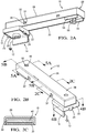
Figures 2A and 2B are first and second perspective views of a first bus bar assembly. -
Figure 2C is a cross-sectional view of the first bus bar assembly taken alongline 2C-2C inFigure 2B . -
Figure 3 is an exploded partial view of the first bus bar assembly. -
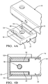
Figure 4A is a partial view of the first bus bar assembly in an unassembled condition with respect to a terminal. -
Figure 4B is cross-sectional view of the first bus bar assembly taken alongline 4B-4B inFigure 2B . -
Figure 5A is cross-sectional view of the first bus bar assembly taken alongline 5A-5A inFigure 2B with the first bus bar assembly connected to the terminal. -
Figure 5B is cross-sectional view of the first bus bar assembly taken alongline 5B-5B inFigure 2B with the first bus bar assembly connected to a terminal. -
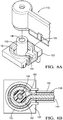
Figures 6A and 6B are first and second perspective views of a second bus bar assembly. -
Figure 6C is a cross-sectional view of the second bus bar assembly taken alongline 6C-6C inFigure 6B . -
Figure 7 is an exploded partial view of the first bus bar assembly. -
Figure 8A is a partial view of the second bus bar assembly in an unassembled condition with respect to a terminal. -
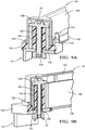
Figure 8B is cross-sectional view of the second bus bar assembly taken alongline 8B-8B inFigure 6B . -
Figure 9A is cross-sectional view of the second bus bar assembly taken alongline 9A-9A inFigure 6B with the second bus bar assembly connected to the terminal. -
Figure 9B is cross-sectional view of the second bus bar assembly taken alongline 9B-9B inFigure 6B with the second bus bar assembly connected to a terminal. - The embodiments, examples and alternatives of the preceding paragraphs, the claims, or the following description and drawings, including any of their various aspects or respective individual features, may be taken independently or in any combination. Features described in connection with one embodiment are applicable to all embodiments, unless such features are incompatible. Like reference numbers and designations in the various drawings indicate like elements.
- A
battery module 10, or battery pack assembly, is schematically illustrated inFigure 1 . Thebattery module 10 includesmultiple battery cells 12 with positive and negativeelectrical terminals terminals 14 of thevarious cells 12 are electrically connected to one another withbus bar assemblies 16 in a configuration that provides sufficient power for large electrical loads, such as automotive hybrid propulsion systems. - Referring to
Figures 2A and3 , the terminal 14 is provided by aterminal pad 18 having a threadedmember 20. In the example, theterminal pad 18 is an L-shaped copper structure, which provides a quadrangular outer surface 17 (Fig. 3 ) to which thebus bar assembly 16 is secured. Other terminal pad shapes may be used. The vertical portion (as depicted in the Figures) of theterminal pad 18 is arranged within the protective nonconductive housing of thecell 12, and is not shown for simplicity. - There is a potential shock hazard when the
outer surface 17 of the terminal 14 is left exposed. To mitigate the shock hazard when connecting and disconnecting thebus bar assembly 16 from thecells 12, a nonconductiveterminal cap 22 is secured to the terminal 14 via anattachment feature 24, for example, snaps. In the example, the snaps engage aperimeter 21 of theterminal pad 18 to retain theterminal cap 22 over the terminal 14. Theperimeter 21 is arranged within and enclosed by theterminal cap 22, as best shown inFigure 2A . - The
terminal cap 22 has a finger-proof slot 54 exposing aterminal portion 19 of theterminal pad 18 in an assembled condition, that is, with theterminal cap 22 secured to the terminal 14. In this disclosure, "finger-proof' means a configuration that meets the standard set forth in IEC 60529 entitled "Degrees of Protection Provided by Enclosures" and code IP2XB relating to finger Ingress Protection. The "test finger" is based upon a solid object 12.5 mm in diameter or more and up to 80 mm long being prevented from entering an enclosure. Furthermore, if a standard test finger 80 mm long and 12 mm in diameter enters the enclosure there will be adequate clearance from live parts, i.e., the terminal. In this manner, the disclosed finger-proof terminal cap 22 prevents a technician from inadvertently touching the terminal 14 with theterminal cap 22 in place, for example, during assembly and/or removal of thebus bar assembly 16 with respect to thecells 12. Theterminal cap 22 can be a loose piece that is permanently attached to theterminals 14. - An example
bus bar assembly 16 is shown inFigures 2A-5B . Thebus bar assembly 16 includes abus bar 40 that is substantially enclosed by anonconductive shroud 26 within acavity 38. Theshroud 26 includes first andsecond shroud portions bus bar 40. In the example illustrated,attachments 32 between the first andsecond shroud portions snaps 36 removably received in correspondingwindows 34. Other attachments may be used if desired. - The
bus bar 40 includes anend 52 that extends through anotch 50 provided at an end of thesecond shroud portion 30 to expose a small portion of theend 52. Onesuch end 52 is provided at each of opposing ends of thebus bar assembly 16. Theend 52 is sized to be received in theslot 54 in the assembled condition in which theend 52 is in electrical contact with theterminal pad 18. The complementary shapes of theend 52 and theslot 54 assist in easily locating thebus bar assembly 16 relative to thecells 12 during assembly. - A
bolt 56 extends through afirst hole 42 in theend 52 of thebus bar 40 and asecond hole 44 in thesecond shroud portion 30. Theterminal cap 22 includes athird hole 46 configured to be aligned with the threadedmember 20 when theterminal cap 22 is installed over theterminal pad 18. Thebolt 56 has first andsecond bolt portions access hole 48 is aligned with a head of thebolt 56 provided on thefirst bolt portion 58. A tool, such as an Allen or Torx wrench for example, can be inserted through theaccess hole 48 to engage the bolt head. Thesecond bolt portion 59 has threads that cooperate with the threadedmember 20 to clamp theend 52 tightly to the terminal 14 when thebolt 56 is torqued to specification to make a good electrical connection. - When the
bus bar assembly 16 is in an assembled condition, theshroud 26 and theterminal cap 22 cooperate to enclose theend 52 so that no portion of thebus bar 40 is left exposed. But, with thebus bar assembly 16 removed, theslot 54 andthird hole 46 only exposes only very smallterminal portions 19, which are finger-proof and not susceptible to touching by the technician. - Various bus bar assembly and terminal cap configurations can be used to provide finger-proofing. The example illustrated in
Figures 2A-5B uses a pair of rectangular spaced apartslots 54. Theend 52 of thebus bar 40 has a U-shape provided bylegs 53. Thelegs 53 are received in theslots 54 and extend through theterminal cap 22 when in the assembled condition to make a mechanical and electrical connection. Thebolt 56 extends through theend 52 and is arranged between thelegs 53. - Another
bus bar assembly 116 andterminal cap 122 configuration is shown inFigures 6A-9B . Like numerals are used to indicate like elements. Thebus bar assembly 116 includes abus bar 140 that is substantially enclosed by a nonconductive shroud 126 within acavity 138. In this example, thebus bar 140 is oriented 90° compared to thebus bar 40. The shroud 126 includes first andsecond shroud portions bus bar 140. Thefirst shroud portion 128 is nested within thesecond shroud portion 130. In the example illustrated,attachments 132 between the first andsecond shroud portions snaps 136 removably received incorresponding windows 134. - The
bus bar 140 includes anend 152 that extends through and is exposed between the first andsecond shroud portions shroud 26, to expose a small portion of theend 152. Onesuch end 152 is provided at each of opposing ends of thebus bar assembly 116. Theend 152 is sized to be received in theslot 154 and extend through theterminal cap 122 in the assembled condition in which theend 152 is in electrical and mechanical contact with theterminal pad 18. - A
bolt 156 extends through a first hole in theend 152 provided by its scroll-like shape. Thebolt 156 extends through a second hole 144 in thesecond shroud portion 30. Theterminal cap 122 includes athird hole 146 configured to be aligned with the threadedmember 20 when theterminal cap 122 is installed over theterminal pad 18. Thebolt 156 has first andsecond bolt portions access hole 148, which is finger-proof, is aligned with a head of thebolt 156 provided on thefirst bolt portion 158. Thesecond bolt portion 159 has threads that cooperate with the threadedmember 20 to clamp theend 152 tightly to the terminal 14 when thebolt 156 is torqued to specification to make a good electrical connection. - With this configuration, the
slot 154 has a first arcuate hook-shape, and theterminal cap 122 includes acylindrical post 160 interiorly arranged with respect to theslot 154. Theend 152 of thebus bar 140 has a correspondingly shaped second arcuate hook-shape that is received in theslot 154 and surrounds thepost 160 in the assembled condition. The term "arcuate" includes cylindrical as well as partially cylindrical shapes. Thebolt 156 is received in thepost 160 in the assembled condition. - In operation, during assembly of the
battery module 10, the nonconductive terminal cap is secured over each conductive terminal, for example, by snapping the terminal cap around the perimeter of the terminal. The terminal cap includes the finger-proof hole and the finger-proof slot exposing a small terminal portion of the terminal. The nonconductive shroud encloses the bus bar with the end extending through shroud. With the bolt captured in the end by the shroud, the end is located in the slot and the bolt is disposed in the hole. The tool is inserted into the access hole in the shroud to engage the bolt, and the bolt is tightened to clamp the end into engagement with the terminal. - In this manner, the terminal cap can be permanently secured to the terminal, rendering the terminal finger-safe. Thus, the battery module is finger-proof even with the bus bar assemblies disconnected, which allows for safe assembly and handling of the battery module during assembly and servicing of the battery module.
- It should also be understood that although a particular component arrangement is disclosed in the illustrated embodiment, other arrangements will benefit herefrom. Although particular step sequences are shown, described, and claimed, it should be understood that steps may be performed in any order, separated or combined unless otherwise indicated and will still benefit from the present invention.
- Although the different examples have specific components shown in the illustrations, embodiments of this invention are not limited to those particular combinations. It is possible to use some of the components or features from one of the examples in combination with features or components from another one of the examples.
- Although an example embodiment has been disclosed, a worker of ordinary skill in this art would recognize that certain modifications would come within the scope of the claims. For that reason, the following claims should be studied to determine their true scope and content.
Claims (15)
- A bus bar assembly (16) comprising:a nonconductive terminal cap (22) configured to secure to an electrically conductive terminal via an attachment feature (24), the terminal cap (22) has a slot (54) configured to expose a terminal portion (19) of the terminal (14) in an assembled condition;a bus bar (40) having an end (52) configured to be received in the slot (54) in the assembled condition in which the end (52) is in electrical contact with the terminal portion (19) of the terminal (14);a nonconductive shroud (26) enclosing the bus bar (40), with the end (52) extending through shroud (26).
- The bus bar assembly (16) of claim 1, wherein the attachment feature (24) includes at least one snap configured to be secured to a perimeter (21) of a terminal pad (18) provided by the terminal (14).
- The bus bar assembly (16) of claim 2, comprising a bolt (56) extending through a first hole (42) in the end (52) of the bus bar (40) and a second hole (44) in the shroud (26), the terminal cap (22) includes a third hole (46) configured to be aligned with a threaded member (20) of the terminal (14), the third hole (46) is finger-proof, and the threaded member (20) configured to receive the bolt (56) in the assembled condition.
- The bus bar assembly (16) of claim 3, wherein the shroud (26) includes first and second shroud portions (28, 30) secured to one another about the bus bar (40), the second hole (44) is provided in the second shroud portion (30) , and the first shroud portion (28) includes an access hole (48) that is finger-proof and is aligned with the bolt (56) and configured to receive a tool that cooperates with a head (58) of the bolt (56).
- The bus bar assembly (16) of any one of the preceding claims, wherein the terminal cap (22) includes a pair of the slot (54), wherein the slot (54) is finger-proof, and the end (52) of the bus bar (40) has a U-shape provided by legs (53), the legs (53) configured to be received in the slots (54), and comprising a bolt (56) extending through the end (52) and configured to secure the bus bar (40) to the terminal (14).
- The bus bar assembly (16) of claim 5, wherein the bolt (56) is arranged between the legs (53).
- The bus bar assembly (16) of any one of the preceding claims, wherein the slot (54) is finger-proof and has a first arcuate hook-shape, and the terminal cap (22) includes a post (160) interiorly arranged with respect to the slot (54), and the end (52) of the bus bar (40) has a second arcuate hook-shape configured to be received in the slot (54) and surround the post (160) in the assembled condition, and comprising a bolt (56) extending through the end (52) of the bus bar (40) and configured to secure the bus bar (40) to the terminal (14).
- The bus bar assembly (16) of claim 7, wherein the bolt (56) is configured to be received in the post (160) in the assembled condition.
- A battery module (10) comprising:a battery cell (12) having a terminal (14) provided by a terminal pad (18) with a threaded member (20);a nonconductive terminal cap (22) secured to the terminal (14) via an attachment feature (24), the terminal cap (22) has a slot (54) exposing a terminal portion (19) of the terminal pad (18) in an assembled condition;a bus bar (40) having an end (52) received in the slot (54) in the assembled condition in which the end (52) is in electrical contact with the terminal pad (18);a nonconductive shroud (26) enclosing the bus bar (40), with the end (52) extending through shroud (26); anda bolt (56) having first and second bolt portions (58, 59), the first bolt portion (58) contained within the shroud (26), and the second bolt portion (59) secured to the threaded member (20) to clamp the end (52) of the bus bar (40) into engagement with the terminal pad (18).
- The battery module of claim 9, wherein the battery cell (12) is a first battery cell, and comprising a second battery cell, wherein the end (52) is a first end, and the bus bar (40) has a second end, wherein the bolt (56) is a first bolt, and comprising a second bolt securing the second end to the second battery cell.
- The battery module of claim 9 or 10, wherein the terminal cap (22) encloses the terminal pad (18) except where the slot (54) is finger-proof and exposes the terminal portion (19) and a hole (46) in the terminal cap (22) exposes the threaded member (20), wherein the hole (46) is finger-proof, the attachment feature (24) includes at least one snap secured to a perimeter (21) of the terminal pad (18).
- The battery module of claim 11, wherein the bolt (56) extends through a first hole (42) in the end (52) of the bus bar (40) and a second hole (44) in the shroud (26), the terminal cap (22) includes a third hole corresponding to the hole (46), the shroud (26) includes first and second shroud portions (28, 30) secured to one another about the bus bar (40), the second hole (44) is provided in the second shroud portion (30), and the first shroud portion (28) includes an access hole (48) that is finger-proof and is aligned with the first bolt portion (58) and configured to receive a tool that cooperates with a head of the first bolt portion (58).
- The battery module of any one of the claims 9 to 12, wherein the terminal cap (22) includes a pair of the slot (54), wherein the slot (54) is finger-proof, and the end (52) of the bus bar (40) has a U-shape provided by legs (53), the legs (53) configured to be received in the slots (54), the bolt (56) extending through the end (52) and configured to secure the bus bar (40) to the terminal (14), and the bolt (56) is arranged between the legs (53).
- The battery module of any one of the claims 9 to 13, wherein the slot (54) is finger-proof and has a first arcuate hook-shape, and the terminal cap (22) includes a post (160) interiorly arranged with respect to the slot (54), and the end (52) of the bus bar (40) has a second arcuate hook-shape configured to be received in the slot (54) and surround the post (160) in the assembled condition, wherein the bolt (56) is received in the post (160) in the assembled condition.
- A method of electrically connecting cells (12) of a battery module (10), comprising the steps of:
securing a nonconductive terminal cap (22) over a conductive battery cell terminal (14), wherein the terminal cap (22) includes a hole (46) and a slot (54) exposing a terminal portion (19) of the terminal (14);a) providing a bus bar assembly (16) with a bus bar (40) having an end (152), a nonconductive shroud (26) enclosing the bus bar (40) with the end (52) extending through a shroud (26), and a bolt (56) is captured in the end (52) by the shroud (26);b) locating the end (52) in the slot (54); andc) securing the bolt (56) to the terminal (14) through the hole (46) to clamp the end (52) into engagement with the terminal (14).
Applications Claiming Priority (1)
| Application Number | Priority Date | Filing Date | Title |
|---|---|---|---|
| US201962865470P | 2019-06-24 | 2019-06-24 |
Publications (2)
| Publication Number | Publication Date |
|---|---|
| EP3758099A1 true EP3758099A1 (en) | 2020-12-30 |
| EP3758099B1 EP3758099B1 (en) | 2026-04-01 |
Family
ID=71138544
Family Applications (3)
| Application Number | Title | Priority Date | Filing Date |
|---|---|---|---|
| EP20181662.6A Active EP3758099B1 (en) | 2019-06-24 | 2020-06-23 | Bolted bus bar with finger-proofing |
| EP20181664.2A Active EP3758100B1 (en) | 2019-06-24 | 2020-06-23 | Blade terminal bus bar with finger-proofing |
| EP25174198.9A Pending EP4571995A3 (en) | 2019-06-24 | 2020-06-23 | Blade terminal bus bar with finger-proofing |
Family Applications After (2)
| Application Number | Title | Priority Date | Filing Date |
|---|---|---|---|
| EP20181664.2A Active EP3758100B1 (en) | 2019-06-24 | 2020-06-23 | Blade terminal bus bar with finger-proofing |
| EP25174198.9A Pending EP4571995A3 (en) | 2019-06-24 | 2020-06-23 | Blade terminal bus bar with finger-proofing |
Country Status (3)
| Country | Link |
|---|---|
| US (4) | US11870165B2 (en) |
| EP (3) | EP3758099B1 (en) |
| CN (3) | CN112134040B (en) |
Cited By (1)
| Publication number | Priority date | Publication date | Assignee | Title |
|---|---|---|---|---|
| EP4080686A1 (en) * | 2021-04-21 | 2022-10-26 | Rosenberger Hochfrequenztechnik GmbH & Co. KG | Electrical connector, electrical connection element and electrical connection |
Families Citing this family (10)
| Publication number | Priority date | Publication date | Assignee | Title |
|---|---|---|---|---|
| CN118448897A (en) * | 2019-05-24 | 2024-08-06 | 株式会社自动网络技术研究所 | Terminal connection structure |
| US10910800B1 (en) * | 2019-10-22 | 2021-02-02 | Rivian Ip Holdings, Llc | Cover assembly for electrical busbar connection |
| US20240072384A1 (en) * | 2020-12-28 | 2024-02-29 | A. Agrati S.P.A. | Coupling device for coupling tab electric terminals of battery cells |
| DE102021100997B3 (en) * | 2021-01-19 | 2022-04-21 | Te Connectivity Germany Gmbh | Module connector with at least one sliding contact arrangement |
| CN115732830A (en) * | 2021-08-28 | 2023-03-03 | 莫列斯有限公司 | Battery connection module and battery pack |
| US11749931B2 (en) * | 2021-12-21 | 2023-09-05 | GM Global Technology Operations LLC | Electrical connection unit for high-voltage battery packs |
| US12482892B2 (en) * | 2022-02-08 | 2025-11-25 | Ford Global Technologies, Llc | Thermal barrier for busbar of traction battery |
| JP7838115B2 (en) * | 2022-05-04 | 2026-03-31 | エルジー エナジー ソリューション リミテッド | Battery system, energy storage system including the battery system, and protective cover used for the battery system. |
| US20230369724A1 (en) * | 2022-05-10 | 2023-11-16 | Rivian Ip Holdings, Llc | Battery pack apparatus |
| WO2026074504A1 (en) * | 2024-10-04 | 2026-04-09 | A. Raymond Et Cie | Cell-to-cell connector |
Citations (3)
| Publication number | Priority date | Publication date | Assignee | Title |
|---|---|---|---|---|
| US5576516A (en) * | 1993-09-13 | 1996-11-19 | Yazaki Corporation | Cover of battery connecting terminal |
| EP0765005A2 (en) * | 1995-09-19 | 1997-03-26 | Sumitomo Wiring Systems, Ltd. | A cover equipped electrical connection device and a cover for an electrical connection device |
| US20060270277A1 (en) * | 2005-05-25 | 2006-11-30 | Weiping Zhao | Canted coil spring power terminal and sequence connection system |
Family Cites Families (24)
| Publication number | Priority date | Publication date | Assignee | Title |
|---|---|---|---|---|
| KR0151534B1 (en) | 1995-10-30 | 1998-08-17 | 이종호 | E. coli mutant strain suppressed organic acid production |
| US6276960B1 (en) | 2000-08-29 | 2001-08-21 | Delphi Technologies, Inc. | Electrical power connector system |
| EP1239506B1 (en) * | 2001-03-07 | 2012-04-25 | Yazaki Corporation | Protective cover and fuse box |
| ES2193849B1 (en) * | 2001-07-31 | 2005-03-01 | S.E. Acumulador Tudor, S.A. | BATTERY OF ELECTRIC ACCUMULATORS. |
| KR100821859B1 (en) | 2006-02-09 | 2008-04-11 | 주식회사 엘지화학 | Battery module with improved safety at electrode terminal connections |
| CN101622735A (en) * | 2007-01-05 | 2010-01-06 | 江森自控帅福得先进能源动力系统有限责任公司 | battery module |
| JP5375440B2 (en) * | 2009-08-26 | 2013-12-25 | 住友電装株式会社 | Male connector and connector device |
| KR101084213B1 (en) | 2009-11-30 | 2011-11-17 | 삼성에스디아이 주식회사 | Battery pack |
| DE102010024519A1 (en) | 2010-06-21 | 2011-12-22 | Tyco Electronics Amp Gmbh | HV battery bridge |
| JP5803405B2 (en) | 2011-08-10 | 2015-11-04 | 株式会社オートネットワーク技術研究所 | Bus bar cover and bus bar with cover |
| JP5934520B2 (en) * | 2012-02-28 | 2016-06-15 | 矢崎総業株式会社 | Insulating cover that covers the case of the busbar module |
| KR20140060633A (en) | 2012-11-12 | 2014-05-21 | 주식회사 엘지화학 | Battery module having bus bar assembly and battery pack comprising the same |
| KR20140094207A (en) * | 2013-01-21 | 2014-07-30 | 삼성에스디아이 주식회사 | Rechargeable battery module |
| US9257772B2 (en) * | 2013-02-08 | 2016-02-09 | Lear Corporation | Electric connector with a lock to retain a terminal within a housing |
| KR102115040B1 (en) | 2014-03-14 | 2020-05-26 | 엘에스이브이코리아 주식회사 | High voltage male type connector |
| US9350127B2 (en) | 2014-03-24 | 2016-05-24 | Ford Global Technologies, Llc | Self-locating busbar assembly and alignment method |
| KR102283792B1 (en) * | 2014-08-25 | 2021-08-02 | 삼성에스디아이 주식회사 | Rechargeable battery module |
| US10396405B2 (en) | 2014-11-10 | 2019-08-27 | Te Connectivity Corporation | Bus bar for a battery connector system |
| US9437860B2 (en) | 2014-11-20 | 2016-09-06 | Ford Global Technologies, Llc | Traction battery assembly having snap-in bus bar module |
| KR102396361B1 (en) | 2015-08-18 | 2022-05-10 | 삼성에스디아이 주식회사 | Battery pack |
| EP3323161B1 (en) * | 2015-09-30 | 2020-01-15 | BYD Company Limited | Connector for power batteries, power battery module, power battery pack and vehicle |
| US10516144B2 (en) * | 2016-02-19 | 2019-12-24 | Gs Yuasa International Ltd. | Energy storage apparatus |
| US10355389B2 (en) * | 2017-08-01 | 2019-07-16 | Delphi Technologies, Llc | High-current electrical terminal |
| US10003112B1 (en) | 2017-12-01 | 2018-06-19 | GM Global Technology Operations LLC | Battery backplane assembly with integrated bus bar connections and thermal management features |
-
2020
- 2020-05-02 US US16/865,315 patent/US11870165B2/en active Active
- 2020-05-02 US US16/865,316 patent/US11404804B2/en active Active
- 2020-06-23 EP EP20181662.6A patent/EP3758099B1/en active Active
- 2020-06-23 EP EP20181664.2A patent/EP3758100B1/en active Active
- 2020-06-23 EP EP25174198.9A patent/EP4571995A3/en active Pending
- 2020-06-24 CN CN202010586768.7A patent/CN112134040B/en active Active
- 2020-06-24 CN CN202411378215.7A patent/CN119381708A/en active Pending
- 2020-06-24 CN CN202010585815.6A patent/CN112133875B/en active Active
-
2022
- 2022-06-27 US US17/849,800 patent/US12355166B2/en active Active
-
2023
- 2023-07-26 US US18/226,397 patent/US12272889B2/en active Active
Patent Citations (3)
| Publication number | Priority date | Publication date | Assignee | Title |
|---|---|---|---|---|
| US5576516A (en) * | 1993-09-13 | 1996-11-19 | Yazaki Corporation | Cover of battery connecting terminal |
| EP0765005A2 (en) * | 1995-09-19 | 1997-03-26 | Sumitomo Wiring Systems, Ltd. | A cover equipped electrical connection device and a cover for an electrical connection device |
| US20060270277A1 (en) * | 2005-05-25 | 2006-11-30 | Weiping Zhao | Canted coil spring power terminal and sequence connection system |
Cited By (1)
| Publication number | Priority date | Publication date | Assignee | Title |
|---|---|---|---|---|
| EP4080686A1 (en) * | 2021-04-21 | 2022-10-26 | Rosenberger Hochfrequenztechnik GmbH & Co. KG | Electrical connector, electrical connection element and electrical connection |
Also Published As
| Publication number | Publication date |
|---|---|
| US20220328987A1 (en) | 2022-10-13 |
| CN112134040B (en) | 2025-07-04 |
| EP3758099B1 (en) | 2026-04-01 |
| US12355166B2 (en) | 2025-07-08 |
| US20230369787A1 (en) | 2023-11-16 |
| US20200403329A1 (en) | 2020-12-24 |
| CN112133875A (en) | 2020-12-25 |
| EP3758100A1 (en) | 2020-12-30 |
| EP3758100B1 (en) | 2025-06-04 |
| US20200403206A1 (en) | 2020-12-24 |
| EP4571995A2 (en) | 2025-06-18 |
| CN112134040A (en) | 2020-12-25 |
| CN112133875B (en) | 2024-09-17 |
| EP4571995A3 (en) | 2025-12-24 |
| US11870165B2 (en) | 2024-01-09 |
| US12272889B2 (en) | 2025-04-08 |
| CN119381708A (en) | 2025-01-28 |
| US11404804B2 (en) | 2022-08-02 |
Similar Documents
| Publication | Publication Date | Title |
|---|---|---|
| US12355166B2 (en) | Bus bar assembly | |
| JP7809258B2 (en) | In-vehicle equipment | |
| US10446988B2 (en) | Fuse assembly | |
| US10978768B2 (en) | Battery system | |
| US8376758B2 (en) | Receptacle with printed circuit board | |
| EP3357136B1 (en) | Sealed modular power distribution apparatus | |
| US20230361509A1 (en) | Electrical power connector assembly | |
| US7548412B2 (en) | Switchable fused power distribution block | |
| WO2022248290A1 (en) | Connector system and safety sleeve for such a system | |
| EP3349318B1 (en) | Surge protection device base | |
| US7696854B2 (en) | Heavy current coupling | |
| CN218351808U (en) | Connecting terminal for electrical equipment and electrical equipment | |
| CN217848382U (en) | Connector, high-voltage electric connection system and vehicle | |
| US20250091457A1 (en) | Charging inlet assembly of a vehicle | |
| US20230387622A1 (en) | Electrical safety connector | |
| EP0627754A1 (en) | A protective arrangement against current overloading with direct fuse coupling to a cable termination |
Legal Events
| Date | Code | Title | Description |
|---|---|---|---|
| PUAI | Public reference made under article 153(3) epc to a published international application that has entered the european phase |
Free format text: ORIGINAL CODE: 0009012 |
|
| STAA | Information on the status of an ep patent application or granted ep patent |
Free format text: STATUS: THE APPLICATION HAS BEEN PUBLISHED |
|
| AK | Designated contracting states |
Kind code of ref document: A1 Designated state(s): AL AT BE BG CH CY CZ DE DK EE ES FI FR GB GR HR HU IE IS IT LI LT LU LV MC MK MT NL NO PL PT RO RS SE SI SK SM TR |
|
| AX | Request for extension of the european patent |
Extension state: BA ME |
|
| STAA | Information on the status of an ep patent application or granted ep patent |
Free format text: STATUS: REQUEST FOR EXAMINATION WAS MADE |
|
| 17P | Request for examination filed |
Effective date: 20210430 |
|
| RBV | Designated contracting states (corrected) |
Designated state(s): AL AT BE BG CH CY CZ DE DK EE ES FI FR GB GR HR HU IE IS IT LI LT LU LV MC MK MT NL NO PL PT RO RS SE SI SK SM TR |
|
| STAA | Information on the status of an ep patent application or granted ep patent |
Free format text: STATUS: EXAMINATION IS IN PROGRESS |
|
| 17Q | First examination report despatched |
Effective date: 20220207 |
|
| RAP3 | Party data changed (applicant data changed or rights of an application transferred) |
Owner name: APTIV TECHNOLOGIES LIMITED |
|
| RAP1 | Party data changed (applicant data changed or rights of an application transferred) |
Owner name: APTIV TECHNOLOGIES AG |
|
| RAP3 | Party data changed (applicant data changed or rights of an application transferred) |
Owner name: APTIV TECHNOLOGIES AG |
|
| REG | Reference to a national code |
Ref country code: DE Ref legal event code: R079 Free format text: PREVIOUS MAIN CLASS: H01M0002200000 Ipc: H01M0050505000 Ref document number: 602020069483 Country of ref document: DE |
|
| RIC1 | Information provided on ipc code assigned before grant |
Ipc: H01M 50/505 20210101AFI20251202BHEP Ipc: H01M 50/55 20210101ALI20251202BHEP Ipc: H01M 50/503 20210101ALI20251202BHEP Ipc: H01M 50/517 20210101ALI20251202BHEP Ipc: H01M 50/553 20210101ALI20251202BHEP Ipc: H01M 50/588 20210101ALI20251202BHEP Ipc: H01M 50/591 20210101ALI20251202BHEP Ipc: H01R 13/11 20060101ALI20251202BHEP Ipc: H01R 11/28 20060101ALI20251202BHEP Ipc: H01R 13/506 20060101ALI20251202BHEP |
|
| GRAP | Despatch of communication of intention to grant a patent |
Free format text: ORIGINAL CODE: EPIDOSNIGR1 |
|
| STAA | Information on the status of an ep patent application or granted ep patent |
Free format text: STATUS: GRANT OF PATENT IS INTENDED |
|
| INTG | Intention to grant announced |
Effective date: 20260113 |
|
| GRAS | Grant fee paid |
Free format text: ORIGINAL CODE: EPIDOSNIGR3 |
|
| GRAA | (expected) grant |
Free format text: ORIGINAL CODE: 0009210 |
|
| STAA | Information on the status of an ep patent application or granted ep patent |
Free format text: STATUS: THE PATENT HAS BEEN GRANTED |
|
| AK | Designated contracting states |
Kind code of ref document: B1 Designated state(s): AL AT BE BG CH CY CZ DE DK EE ES FI FR GB GR HR HU IE IS IT LI LT LU LV MC MK MT NL NO PL PT RO RS SE SI SK SM TR |
|
| P01 | Opt-out of the competence of the unified patent court (upc) registered |
Free format text: CASE NUMBER: UPC_APP_0006285_3758099/2026 Effective date: 20260220 |
|
| REG | Reference to a national code |
Ref country code: CH Ref legal event code: F10 Free format text: ST27 STATUS EVENT CODE: U-0-0-F10-F00 (AS PROVIDED BY THE NATIONAL OFFICE) Effective date: 20260401 Ref country code: GB Ref legal event code: FG4D |
|
| REG | Reference to a national code |
Ref country code: IE Ref legal event code: FG4D |
|
| REG | Reference to a national code |
Ref country code: DE Ref legal event code: R096 Ref document number: 602020069483 Country of ref document: DE |