EP3758088A1 - Assembled battery - Google Patents
Assembled battery Download PDFInfo
- Publication number
- EP3758088A1 EP3758088A1 EP19758229.9A EP19758229A EP3758088A1 EP 3758088 A1 EP3758088 A1 EP 3758088A1 EP 19758229 A EP19758229 A EP 19758229A EP 3758088 A1 EP3758088 A1 EP 3758088A1
- Authority
- EP
- European Patent Office
- Prior art keywords
- bottom part
- lower case
- walls
- pair
- upper case
- Prior art date
- Legal status (The legal status is an assumption and is not a legal conclusion. Google has not performed a legal analysis and makes no representation as to the accuracy of the status listed.)
- Pending
Links
- 239000000463 material Substances 0.000 claims description 9
- 229920003002 synthetic resin Polymers 0.000 claims description 9
- 239000000057 synthetic resin Substances 0.000 claims description 9
- 238000005187 foaming Methods 0.000 claims description 7
- 238000003466 welding Methods 0.000 abstract description 7
- 238000012986 modification Methods 0.000 description 18
- 230000004048 modification Effects 0.000 description 18
- 239000000853 adhesive Substances 0.000 description 13
- 230000001070 adhesive effect Effects 0.000 description 13
- 238000000034 method Methods 0.000 description 6
- -1 polyethylene Polymers 0.000 description 5
- 229920005989 resin Polymers 0.000 description 5
- 239000011347 resin Substances 0.000 description 5
- 229920001955 polyphenylene ether Polymers 0.000 description 4
- 229920000106 Liquid crystal polymer Polymers 0.000 description 2
- 239000004977 Liquid-crystal polymers (LCPs) Substances 0.000 description 2
- 229930040373 Paraformaldehyde Natural products 0.000 description 2
- 239000004697 Polyetherimide Substances 0.000 description 2
- 239000004698 Polyethylene Substances 0.000 description 2
- 239000004734 Polyphenylene sulfide Substances 0.000 description 2
- 239000004743 Polypropylene Substances 0.000 description 2
- 229920000122 acrylonitrile butadiene styrene Polymers 0.000 description 2
- 239000004676 acrylonitrile butadiene styrene Substances 0.000 description 2
- XECAHXYUAAWDEL-UHFFFAOYSA-N acrylonitrile butadiene styrene Chemical compound C=CC=C.C=CC#N.C=CC1=CC=CC=C1 XECAHXYUAAWDEL-UHFFFAOYSA-N 0.000 description 2
- 229920001893 acrylonitrile styrene Polymers 0.000 description 2
- 239000000956 alloy Substances 0.000 description 2
- 229910045601 alloy Inorganic materials 0.000 description 2
- 238000013461 design Methods 0.000 description 2
- 229920011301 perfluoro alkoxyl alkane Polymers 0.000 description 2
- 229920002492 poly(sulfone) Polymers 0.000 description 2
- 229920001707 polybutylene terephthalate Polymers 0.000 description 2
- 229920000515 polycarbonate Polymers 0.000 description 2
- 239000004417 polycarbonate Substances 0.000 description 2
- 229920001601 polyetherimide Polymers 0.000 description 2
- 229920000573 polyethylene Polymers 0.000 description 2
- 229920000139 polyethylene terephthalate Polymers 0.000 description 2
- 239000005020 polyethylene terephthalate Substances 0.000 description 2
- 229920006324 polyoxymethylene Polymers 0.000 description 2
- 229920000069 polyphenylene sulfide Polymers 0.000 description 2
- 229920001155 polypropylene Polymers 0.000 description 2
- SCUZVMOVTVSBLE-UHFFFAOYSA-N prop-2-enenitrile;styrene Chemical compound C=CC#N.C=CC1=CC=CC=C1 SCUZVMOVTVSBLE-UHFFFAOYSA-N 0.000 description 2
- 229910000838 Al alloy Inorganic materials 0.000 description 1
- JOYRKODLDBILNP-UHFFFAOYSA-N Ethyl urethane Chemical compound CCOC(N)=O JOYRKODLDBILNP-UHFFFAOYSA-N 0.000 description 1
- HBBGRARXTFLTSG-UHFFFAOYSA-N Lithium ion Chemical compound [Li+] HBBGRARXTFLTSG-UHFFFAOYSA-N 0.000 description 1
- 229920000299 Nylon 12 Polymers 0.000 description 1
- 229920002292 Nylon 6 Polymers 0.000 description 1
- 229920002302 Nylon 6,6 Polymers 0.000 description 1
- 229920007019 PC/ABS Polymers 0.000 description 1
- 229920012266 Poly(ether sulfone) PES Polymers 0.000 description 1
- 239000004793 Polystyrene Substances 0.000 description 1
- XAGFODPZIPBFFR-UHFFFAOYSA-N aluminium Chemical compound [Al] XAGFODPZIPBFFR-UHFFFAOYSA-N 0.000 description 1
- 229910052782 aluminium Inorganic materials 0.000 description 1
- 229920006127 amorphous resin Polymers 0.000 description 1
- 229920001577 copolymer Polymers 0.000 description 1
- 238000012937 correction Methods 0.000 description 1
- 230000008878 coupling Effects 0.000 description 1
- 238000010168 coupling process Methods 0.000 description 1
- 238000005859 coupling reaction Methods 0.000 description 1
- 229920006038 crystalline resin Polymers 0.000 description 1
- 239000006260 foam Substances 0.000 description 1
- 238000003780 insertion Methods 0.000 description 1
- 230000037431 insertion Effects 0.000 description 1
- 229910001416 lithium ion Inorganic materials 0.000 description 1
- SQEHCNOBYLQFTG-UHFFFAOYSA-M lithium;thiophene-2-carboxylate Chemical compound [Li+].[O-]C(=O)C1=CC=CS1 SQEHCNOBYLQFTG-UHFFFAOYSA-M 0.000 description 1
- 239000011255 nonaqueous electrolyte Substances 0.000 description 1
- 229920006122 polyamide resin Polymers 0.000 description 1
- 229920001225 polyester resin Polymers 0.000 description 1
- 239000004645 polyester resin Substances 0.000 description 1
- 239000011112 polyethylene naphthalate Substances 0.000 description 1
- 239000011116 polymethylpentene Substances 0.000 description 1
- 229920005672 polyolefin resin Polymers 0.000 description 1
- 239000007921 spray Substances 0.000 description 1
- 238000006467 substitution reaction Methods 0.000 description 1
- 229920002994 synthetic fiber Polymers 0.000 description 1
- 229920005992 thermoplastic resin Polymers 0.000 description 1
Images



Classifications
-
- H—ELECTRICITY
- H01—ELECTRIC ELEMENTS
- H01M—PROCESSES OR MEANS, e.g. BATTERIES, FOR THE DIRECT CONVERSION OF CHEMICAL ENERGY INTO ELECTRICAL ENERGY
- H01M50/00—Constructional details or processes of manufacture of the non-active parts of electrochemical cells other than fuel cells, e.g. hybrid cells
- H01M50/20—Mountings; Secondary casings or frames; Racks, modules or packs; Suspension devices; Shock absorbers; Transport or carrying devices; Holders
- H01M50/233—Mountings; Secondary casings or frames; Racks, modules or packs; Suspension devices; Shock absorbers; Transport or carrying devices; Holders characterised by physical properties of casings or racks, e.g. dimensions
- H01M50/24—Mountings; Secondary casings or frames; Racks, modules or packs; Suspension devices; Shock absorbers; Transport or carrying devices; Holders characterised by physical properties of casings or racks, e.g. dimensions adapted for protecting batteries from their environment, e.g. from corrosion
-
- H—ELECTRICITY
- H01—ELECTRIC ELEMENTS
- H01M—PROCESSES OR MEANS, e.g. BATTERIES, FOR THE DIRECT CONVERSION OF CHEMICAL ENERGY INTO ELECTRICAL ENERGY
- H01M50/00—Constructional details or processes of manufacture of the non-active parts of electrochemical cells other than fuel cells, e.g. hybrid cells
- H01M50/20—Mountings; Secondary casings or frames; Racks, modules or packs; Suspension devices; Shock absorbers; Transport or carrying devices; Holders
- H01M50/204—Racks, modules or packs for multiple batteries or multiple cells
- H01M50/207—Racks, modules or packs for multiple batteries or multiple cells characterised by their shape
- H01M50/209—Racks, modules or packs for multiple batteries or multiple cells characterised by their shape adapted for prismatic or rectangular cells
-
- H—ELECTRICITY
- H01—ELECTRIC ELEMENTS
- H01M—PROCESSES OR MEANS, e.g. BATTERIES, FOR THE DIRECT CONVERSION OF CHEMICAL ENERGY INTO ELECTRICAL ENERGY
- H01M50/00—Constructional details or processes of manufacture of the non-active parts of electrochemical cells other than fuel cells, e.g. hybrid cells
- H01M50/20—Mountings; Secondary casings or frames; Racks, modules or packs; Suspension devices; Shock absorbers; Transport or carrying devices; Holders
- H01M50/218—Mountings; Secondary casings or frames; Racks, modules or packs; Suspension devices; Shock absorbers; Transport or carrying devices; Holders characterised by the material
- H01M50/22—Mountings; Secondary casings or frames; Racks, modules or packs; Suspension devices; Shock absorbers; Transport or carrying devices; Holders characterised by the material of the casings or racks
- H01M50/227—Organic material
-
- H—ELECTRICITY
- H01—ELECTRIC ELEMENTS
- H01M—PROCESSES OR MEANS, e.g. BATTERIES, FOR THE DIRECT CONVERSION OF CHEMICAL ENERGY INTO ELECTRICAL ENERGY
- H01M50/00—Constructional details or processes of manufacture of the non-active parts of electrochemical cells other than fuel cells, e.g. hybrid cells
- H01M50/20—Mountings; Secondary casings or frames; Racks, modules or packs; Suspension devices; Shock absorbers; Transport or carrying devices; Holders
- H01M50/233—Mountings; Secondary casings or frames; Racks, modules or packs; Suspension devices; Shock absorbers; Transport or carrying devices; Holders characterised by physical properties of casings or racks, e.g. dimensions
- H01M50/238—Flexibility or foldability
-
- H—ELECTRICITY
- H01—ELECTRIC ELEMENTS
- H01M—PROCESSES OR MEANS, e.g. BATTERIES, FOR THE DIRECT CONVERSION OF CHEMICAL ENERGY INTO ELECTRICAL ENERGY
- H01M50/00—Constructional details or processes of manufacture of the non-active parts of electrochemical cells other than fuel cells, e.g. hybrid cells
- H01M50/20—Mountings; Secondary casings or frames; Racks, modules or packs; Suspension devices; Shock absorbers; Transport or carrying devices; Holders
- H01M50/289—Mountings; Secondary casings or frames; Racks, modules or packs; Suspension devices; Shock absorbers; Transport or carrying devices; Holders characterised by spacing elements or positioning means within frames, racks or packs
- H01M50/291—Mountings; Secondary casings or frames; Racks, modules or packs; Suspension devices; Shock absorbers; Transport or carrying devices; Holders characterised by spacing elements or positioning means within frames, racks or packs characterised by their shape
-
- H—ELECTRICITY
- H01—ELECTRIC ELEMENTS
- H01M—PROCESSES OR MEANS, e.g. BATTERIES, FOR THE DIRECT CONVERSION OF CHEMICAL ENERGY INTO ELECTRICAL ENERGY
- H01M50/00—Constructional details or processes of manufacture of the non-active parts of electrochemical cells other than fuel cells, e.g. hybrid cells
- H01M50/50—Current conducting connections for cells or batteries
-
- H—ELECTRICITY
- H01—ELECTRIC ELEMENTS
- H01M—PROCESSES OR MEANS, e.g. BATTERIES, FOR THE DIRECT CONVERSION OF CHEMICAL ENERGY INTO ELECTRICAL ENERGY
- H01M50/00—Constructional details or processes of manufacture of the non-active parts of electrochemical cells other than fuel cells, e.g. hybrid cells
- H01M50/50—Current conducting connections for cells or batteries
- H01M50/502—Interconnectors for connecting terminals of adjacent batteries; Interconnectors for connecting cells outside a battery casing
-
- H—ELECTRICITY
- H01—ELECTRIC ELEMENTS
- H01M—PROCESSES OR MEANS, e.g. BATTERIES, FOR THE DIRECT CONVERSION OF CHEMICAL ENERGY INTO ELECTRICAL ENERGY
- H01M50/00—Constructional details or processes of manufacture of the non-active parts of electrochemical cells other than fuel cells, e.g. hybrid cells
- H01M50/50—Current conducting connections for cells or batteries
- H01M50/502—Interconnectors for connecting terminals of adjacent batteries; Interconnectors for connecting cells outside a battery casing
- H01M50/503—Interconnectors for connecting terminals of adjacent batteries; Interconnectors for connecting cells outside a battery casing characterised by the shape of the interconnectors
-
- Y—GENERAL TAGGING OF NEW TECHNOLOGICAL DEVELOPMENTS; GENERAL TAGGING OF CROSS-SECTIONAL TECHNOLOGIES SPANNING OVER SEVERAL SECTIONS OF THE IPC; TECHNICAL SUBJECTS COVERED BY FORMER USPC CROSS-REFERENCE ART COLLECTIONS [XRACs] AND DIGESTS
- Y02—TECHNOLOGIES OR APPLICATIONS FOR MITIGATION OR ADAPTATION AGAINST CLIMATE CHANGE
- Y02E—REDUCTION OF GREENHOUSE GAS [GHG] EMISSIONS, RELATED TO ENERGY GENERATION, TRANSMISSION OR DISTRIBUTION
- Y02E60/00—Enabling technologies; Technologies with a potential or indirect contribution to GHG emissions mitigation
- Y02E60/10—Energy storage using batteries
Definitions
- Embodiments of the present invention relates to a battery pack.
- a battery pack includes a combination of secondary battery cells, in which the positive and negative-electrode terminals of the secondary battery cells are electrically connected to each other via busbars.
- Patent Document 1 Japanese Laid-open Patent Publication Application No. 2003-68260
- a battery pack includes a lower case having a rectangular box shape with a top opened, the lower case including a bottom part, a plurality of first walls extending from the bottom part in a direction substantially orthogonal to the bottom part with given spacing from one pair of sides of the bottom part, and second walls extending from the other pair of sides of the bottom part in the direction substantially orthogonal to the bottom part; an upper case having a rectangular box shape with a bottom opened, the upper case including a top part opposing the lower case; and a plurality of secondary batteries each including a top face provided with a positive-electrode terminal and a negative-electrode terminal, a pair of principal faces extending from a pair of long sides of the top face in a direction substantially orthogonal to the top face, a pair of lateral faces extending between the principal faces, and a bottom face opposing the top face, the secondary batteries being housed between the first walls of the lower case such that the bottom faces oppose the bottom part.
- FIG. 1 is a perspective view of a battery pack 1 according to an embodiment
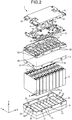
- FIG. 2 is an exploded perspective view of the battery pack 1 of the embodiment.
- the battery pack 1 includes a lower case 2 of a rectangular box-shape with a top opened, an upper case 3 of a rectangular box shape with a bottom opened, and coupled to the opened top of the lower case 2, and a lid 4 of a rectangular box shape with a bottom opened, covering the top part of the upper case 3.
- the components and parts of the lower case 2, the upper case 3, and the lid 4 contain a synthetic resin material having insulting properties (modified polyphenylene ether (PPE) or perfluoroalkoxy alkanes, tetrafluoroethylene-perfluoroalkyl vinyl ether copolymer (PFA), for example).
- a synthetic resin material having insulting properties modified polyphenylene ether (PPE) or perfluoroalkoxy alkanes, tetrafluoroethylene-perfluoroalkyl vinyl ether copolymer (PFA), for example).
- the synthetic resin can be a thermoplastic resin; examples thereof include olefin resins such as polyethylene (PE), polypropylene (PP), and polymethylpentene (PMP); polyester resins such as polyethylene terephthalate (PET), polybutylene terephthalate (PBT), and polyethylene naphthalate (PEN); polyamide resins such as a polyoxymethylene (POM) resin, polyamide 6 (PA6), polyamide 66 (PA66), and polyamide 12 (PA12); crystalline resins such as a polyphenylene sulfide (PPS) resin and a liquid crystal polymer (LCP) resin and alloy resins thereof; and amorphous resins such as polystyrene (PS), polycarbonate (PC), polycarbonate/acrylonitrile-butadiene-styrene (PC/ABS), ABS, acrylonitrile-styrene (AS), modified polyphenylene ether (PPE), polyethersulfone (PES), polyether
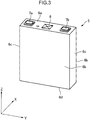
- a casing includes the lower case 2, the upper case 3, and the lid 4, and houses inside a plurality of secondary battery cells 5 illustrated in FIG. 3 along the thickness of the secondary battery cells 5 (in X direction).
- Each secondary battery cell 5 represents a nonaqueous electrolyte secondary battery such as a lithium-ion battery, is formed of aluminum or an aluminum alloy, and has a flat or substantially rectangular parallelepiped shape, for example.
- the secondary battery cell 5 includes a top face 6a, a pair of principal faces 6b extending from a pair of long sides of the top face 6a in a direction substantially orthogonal to the top face (in Z direction), a pair of lateral faces 6c extending between the principal faces 6b, and a bottom face 6d opposing the top face 6a.
- the top face 6a of the secondary battery cell 5 is provided with two types of terminals, i.e., a positive electrode 7a and a negative electrode 7b, at both ends in a longitudinal direction Y.
- the positive-electrode terminal 7a and the negative-electrode terminal 7b are electrically connected to an electrode (not illustrated) housed inside the secondary battery cell 5.
- the secondary battery cell 5 may be provided with a gas exhaust valve 8 that discharges gas if occurs inside.
- FIG. 5 is an XZ sectional view of the lower case 2 provided with the deformable ribs 17,
- FIG. 6 is a perspective view of a deformable rib 17, and
- FIG. 7 is an enlarged view of FIG. 5 .
- the deformable ribs 17 extend from the bottom part 15 to the first walls 13 of the lower case 2.
- the deformable ribs 17 are formed of a synthetic resin material similar to that of the lower case 2 and has a form of triangular pyramid with the first wall 13 as one lateral face and the bottom part 15 as a bottom face, for example, as illustrated in FIG. 6 .
- the angle (the letter c in FIG. 6 ) between the bottom part 15 and a ridgeline 17a of the triangular pyramid of the deformable rib 17 is preferably set to 45 degrees or more.
- the distance from the intersection between the ridgeline 17a of the deformable rib 17 and the first wall 13 to the bottom is preferably set to 2 to 3 mm.
- the length indicated by the letter b that is, the distance from the intersection between the ridgeline 17a of the deformable rib 17 and the bottom part 15 to the first wall 13 is preferably set to 0.5 to 1.5 mm.
- an appropriate film thickness varies depending on the design of the secondary battery cell 5 or the cases, therefore, this is not limiting.
- the shape of the deformable ribs 17 is not limited to the triangular pyramid and the deformable ribs 17 may be optionally shaped as long as the distance from the first wall 13 to the end face of the deformable rib 17 gradually increases in a direction opposite the Z-axial direction (toward the bottom part 15). Meanwhile, the positioning ribs 18 each have a face parallel to the principal faces 10 or the lateral faces 6c of an exterior container 6.
- FIG. 6 is a sectional view of part of the bottom part 15 of the lower case 2.
- the deformable rib 17 is drawn as a triangle while the positioning rib 18 is drawn as a rectangle.
- the positioning ribs 18 are more away from the central part of the secondary battery cells 5 in the Y-axial direction than the deformable ribs 17.
- the deformable ribs 17 are preferably lower in height than the positioning ribs 18 in the Z-axial direction.
- the secondary battery cell is corrected in position in the XY plane, and then positioned in the Z direction by the deformable ribs 17.
- the secondary battery cell contacts with the ribs in this order, which makes it possible to decrease an amount of deformation of the deformable ribs 17 to a minimum, and enables the deformable ribs 17 to appropriately apply a repulsive force to the secondary battery cell 5.
- the upper case 3 is described next with reference to FIG. 2 and FIG. 8 .
- the upper case 3 has a rectangular box shape with a bottom opened and includes a top part 20, a plurality of third walls 23, and fourth walls 24.
- the third walls 23 extend with given spacing from one pair of sides of the top part 20 in a direction substantially orthogonal to the top part.
- the fourth walls 24 extend from the other side pair of the bottom part in the direction substantially orthogonal to the bottom part.
- the top part 20 opposes the top of the secondary battery cell 5.
- the part of the upper case 3, corresponding to the positive-electrode terminal 7a and the negative-electrode terminal 7b of the secondary battery cell 5, is provided with openings 3a and 3b.
- the positive-electrode terminal 7a and the negative-electrode terminal 7b of each secondary battery cell 5 pass through the openings 3a and 3b, respectively, and are electrically connected to each other through the busbar 12 set on the face of the upper case 3 not opposing the top face 6a of the secondary battery cell 5.
- the upper case 3 is further provided with a gas exhaust opening 3c at the part corresponding to the gas exhaust valve 8 of the secondary battery cell 5.
- the bottom part of the outer circumferential wall of the upper case 3 is provided with the snap fits 31 which fit into the fixing holes 16 of the lower case 2 to couple and fix the lower case 2 and the upper case 3 together.
- the top part of the outer circumferential wall of the upper case 3 is provided with fixing holes 32.
- the lid 4 is also provided with snap fits 41 on the outer circumference.
- the snap fits 41 fit into the fixing holes of the upper case 3, to couple and fix the lid 4 and the upper case 3 together.
- the battery pack 1 includes a board 20 that monitors and controls the secondary battery cells 5, between the lid 4 and the upper case 3, for example.
- the battery cell 5 is inserted into a space defined by the first walls 13, the second walls 14, and the bottom part 15 of the lower case 2.
- the upper case 3 is coupled to the lower case 2 so that the positive-electrode terminal 7a and the negative-electrode terminal 7b of the secondary battery cell 5 are inserted through the opening 3a and the opening 3b of the upper case 3, respectively.
- the busbar 12 is then set on the face of the upper case 3 not opposing the lower case 2, and the terminal connecting faces of the busbar 12 are in contact with the positive-electrode terminal 7a and the negative-electrode terminal 7b and connected together by welding, for example.
- the bottom face 6d or the principal faces 10 of the secondary battery cell 5 come(s) into contact with the positioning ribs 18 of the lower case 2.
- the positioning ribs 18 differ from the deformable ribs 17 in having the face parallel to the principal faces 10 or the lateral faces 6c of the exterior container 6.
- the insertion of the secondary battery cell 5 into the lower case 2 does not cause deformation of the positioning ribs 18.
- the secondary battery cell 5 is inserted into the lower case 2 in contact with the positioning ribs 18, whereby the secondary battery cell 5 is accurately corrected in position in the X-axial direction.
- the deformable ribs 17 differ from the positioning ribs 18 in having the face not parallel to the principal faces 10 or the lateral faces of the exterior container 6.
- the deformable ribs 17 have a triangular pyramid shape with the top part 20 of the upper case 3 as a bottom face, for example.
- the shape of the deformable ribs 17 is not limited to the triangular pyramid, and the deformable ribs may be optionally shaped as long as the distance from the third wall 23 to the end face of the deformable rib 17 gradually increases in the Z-axial direction.
- the lower case 2 includes such deformable ribs 17 and positioning ribs 18, so that when inserting the secondary battery cell 5 into the lower case 2, the secondary battery cell 5 comes into contact with the face not parallel to the principal faces 10 or the lateral faces 6c of the exterior container 6.
- the deformable ribs 17 are crushed in the direction from the open side toward the bottom of the lower case 2.
- the deformable rib 17 with the triangular pyramid shape as above the secondary battery cell 5 comes into contact with one side of the triangular pyramid, therefore, the deformable rib 17 is more easily deformable.
- the deformable rib 17, while deforming applies a repulsive force to the secondary battery cell 5 toward the lower case 2 (downward in the Z-axial direction).
- the upper case 3 is coupled to the lower case 2 with the snap fits 31, for example.
- the deformable ribs 17 then work to press the secondary battery cell 5 to the upper case 3 and press the top face 6a against the upper case 3.
- the positive-electrode terminal 7a and the negative-electrode terminal 7b are aligned in the Z-axial direction.
- the positioning ribs 18 serve to fix the secondary battery cell 5 in an accurate position in the XY plane, so that the positive-electrode terminal 7a and the negative-electrode terminal 7b can be inserted through the openings 3a and 3b of the upper case 3, respectively.
- the terminal connecting faces of the busbar 12 are prevented from being misaligned and can contact with and be accurately welded to the positive-electrode terminal 7a and the negative-electrode terminal 7b.
- FIG. 9 is an XZ sectional view of a housing of the secondary battery cell 5 surrounded by the first walls 13, the second walls 14, and the bottom part 15 of the lower case 2.
- the first modification differs from the embodiment in that the lower case 2 includes a protrusion 19 in place of the deformable ribs 17.
- the bottom of the lower case 2 is partially deformed in a direction opposite to the secondary battery cell 5.
- the protrusion 19 may extend linearly or in a dot form in the Y-axial direction.
- the bottom face 6d of the secondary battery cell 5 comes into contact with the protrusion 19.
- the protrusion 19 is preferably elastic.
- the bottom face 6d of the secondary battery cell 5 comes into contact with the protrusion 19 and then receives a repulsive force toward the upper case 3 (in the Z-axial direction).
- the terminal connecting faces of the busbar 12 are prevented from being misaligned, and can contact with the positive-electrode terminal 7a and the negative-electrode terminal 7b and be correctly welded thereto.
- the elastic layer 21 generates an elastic force that presses the secondary battery cell 5.
- the elastic layer 21 formed on the bottom part 15 thus exerts a force on the secondary battery cell 5 in a direction toward the upper case 3 (Z-axial direction).
- the elastic layer 21 may extend along the first walls 13.
- the elastic layer 21 is made of a foaming synthetic resin material (a foaming material such as foaming urethane).
- the elastic layer 21 is porous containing air bubbles, by way of an example.
- the elastic layer 21 is formed of a foaming synthetic resin material as an example.
- the foaming synthetic material is applied to the lower case 2 with a spray nozzle, for example, and subjected to heat. Thereby, the foaming synthetic resin material foams to gain elasticity, and the elastic layer 21 made of elastic synthetic resin material is formed. It is thus possible to easily obtain the elastic layer 21 that supports the secondary battery cell 5, as an example.
- FIG. 11 is an XZ sectional view of the housing of the secondary battery cell 5 surrounded by the first walls 13, the second walls 14, and the bottom part 15 of the lower case 2. As illustrated in FIG. 11 , the adhesive 22 lies on the bottom part 15 of the lower case 2. Thus, the adhesive 22 applies a repulsive force to the secondary battery cell 5 in the direction toward the upper case 3 (Z-axial direction).
- the adhesive 22 may have a film thickness of preferably 0.1 mm to 0.3 mm. However, an appropriate film thickness varies depending on the design of the secondary battery cell 5 or the cases, therefore, this is not limiting.
- the terminal connecting faces of the busbar 12 are prevented from being misaligned and can contact with the positive-electrode terminal 7a and the negative-electrode terminal 7b and be correctly welded thereto.
- the secondary battery cell 5 is vertically secured by the elastic layer 21, the adhesive 22, or the protrusion 19 of the lower case 2 and the deformable ribs 25 of the upper case 3. That is, the secondary battery cell 5 can be more stably secured inside the battery pack.
- the secondary battery cell 5 can be more stably secured inside the battery pack by applying an adhesive to the top face 6a of the upper case 3.
- the third modification has the same structure as the second modification except for part of the upper case 3.
- the upper case 3 are provided with channels 26 at part of the top part 20 adjacent to the third walls 23.
- the channels 26 extend in the Y-axial direction along the third walls 23.
- the depth of the channels 26 is preferably set to 0.1 mm to 0.3 mm; however, this is not limiting.
- an excessive adhesive 22 flows into the channels 26 when the secondary battery cell 5 contacts with the top part 20 of the upper case 3 for assembly of the battery pack.
- the excessive adhesive 22 is accumulated and hardened between the top part 20 of the upper case 3 and the secondary battery cell 5. This can reduce the possibility of misaligning the secondary battery cell 5 in the Z-axial direction. It is thus possible to lower the possibility of misaligning the positive-electrode terminal 7a and the negative-electrode terminal 7b of the secondary battery cell 5, and lower the possibility of improperly welding the busbar to the terminals.
- FIG. 13 is a partial enlarged view of an XZ section of the upper case 3.
- the present modification has the same structure as the second modification except for part of the upper case 3.
- the deformable ribs 25 are located in second channels 27 in the top part 20 of the upper case 3.
- the second channels 27 extend adjacent to the third walls 23.
- the top face 6a of the secondary battery cell 5, when housed in the upper case 3, abuts on the top part 20 of the upper case 3 with no second channels 27 formed.
- the top face 6a abuts on a protrusion defined between the second channels 27 by the second channels 27 of the top part 20.
- the deformable ribs 25 are deformed by the secondary battery cell 5.
- the deformable ribs 25 deform inside the second channels 27.
- FIG. 14 is an XY sectional view of the third walls 23 and the deformable rib 25 of the upper case 3. This modification has the same structure as the second modification except for part of the upper case 3.
- the third walls 23 of the upper case 3 are provided with slits 28 at a part adjacent to the deformable rib 25.
- the deformable rib 25 is preferably interposed between the adjacent slits 28.
- the deformable ribs 25 are deformed by the secondary battery cell 5.
- the deformable ribs 25 fall down away from the secondary battery cell 5 (in X-axial direction, for example) together with the third walls 23 including the deformable ribs 25.
- the slits 28 may pass through the third walls 23 to be able to eliminate larger misalignment. However, the slits 28 may not pass therethrough.
- FIG. 15 is a sectional view of part of the lower case 2 and deformable ribs 17.
- FIG. 15 illustrates the lower case 2 of the battery pack when installed, with upper faces in upper position and lower faces in lower position.
- the deformable ribs 17 are located asymmetric to the wall surfaces.
- the lower faces are provided with a larger number of deformable ribs 17.
- the lower faces receiving a larger load are provided with a larger number of deformable ribs 17, which can more stably secure the secondary battery cells 5.
Landscapes
- Chemical & Material Sciences (AREA)
- Chemical Kinetics & Catalysis (AREA)
- Electrochemistry (AREA)
- General Chemical & Material Sciences (AREA)
- Battery Mounting, Suspending (AREA)
- Connection Of Batteries Or Terminals (AREA)
Abstract
Description
- Embodiments of the present invention relates to a battery pack.
- In recent years, battery packs have been more widely used for power supply for vehicles, electronic devices, and other industrial purposes. For the purpose of increased capacity, a battery pack includes a combination of secondary battery cells, in which the positive and negative-electrode terminals of the secondary battery cells are electrically connected to each other via busbars.
- Patent Document 1: Japanese Laid-open Patent Publication Application No.
2003-68260 - The busbars may be connected to the terminals by welding. In such a case, misalignment of terminals may cause improper welding. In spite of proper welding, the busbars may receive a load and be damaged by vibrations of the battery pack during use. In view of this, an object of the present invention is to provide a battery pack that can reduce improper welding of busbars and reduce a load to the busbars.
- In view of solving the above problem, according to one embodiment, a battery pack includes a lower case having a rectangular box shape with a top opened, the lower case including a bottom part, a plurality of first walls extending from the bottom part in a direction substantially orthogonal to the bottom part with given spacing from one pair of sides of the bottom part, and second walls extending from the other pair of sides of the bottom part in the direction substantially orthogonal to the bottom part; an upper case having a rectangular box shape with a bottom opened, the upper case including a top part opposing the lower case; and a plurality of secondary batteries each including a top face provided with a positive-electrode terminal and a negative-electrode terminal, a pair of principal faces extending from a pair of long sides of the top face in a direction substantially orthogonal to the top face, a pair of lateral faces extending between the principal faces, and a bottom face opposing the top face, the secondary batteries being housed between the first walls of the lower case such that the bottom faces oppose the bottom part. The lower case includes deformable ribs extending from the bottom part to the first walls. The deformable ribs are partially crushed in a direction from an open side toward the bottom part of the lower case.
-
-
FIG. 1 is a battery pack according to an embodiment; -
FIG. 2 is an exploded perspective view of the battery pack of according to an embodiment; -
FIG. 3 is a perspective view of a secondary battery according to an embodiment; -
FIG. 4 is a perspective view of a lower case according to an embodiment; -
FIG. 5 is a sectional view of the lower case according to an embodiment; -
FIG. 6 is a perspective view of a deformable rib according to an embodiment; -
FIG. 7 is a partial sectional view of the lower case including the deformable rib according to an embodiment; -
FIG. 8 is a perspective view of an upper case according to an embodiment; -
FIG. 9 is a partial sectional view of the lower case according to an embodiment; -
FIG. 10 is a partial sectional view of the lower case according to an embodiment; -
FIG. 11 is a partial sectional view of the lower case according to an embodiment; -
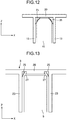
FIG. 12 is a partial sectional view of the upper case according to an embodiment; -
FIG. 13 is a partial sectional view of the upper case according to an embodiment; -
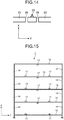
FIG. 14 is a partial sectional view of the upper case according to an embodiment; and -
FIG. 15 is a partial sectional view of the lower case according to an embodiment. - The following will describe embodiments with reference to the accompanying drawings. In the drawings, directions (X direction, Y direction, and Z direction) are defined for the sake of convenience. The X direction, the Y direction, and the Z direction are orthogonal to one another.
-
FIG. 1 is a perspective view of abattery pack 1 according to an embodiment, andFIG. 2 is an exploded perspective view of thebattery pack 1 of the embodiment. Thebattery pack 1 includes alower case 2 of a rectangular box-shape with a top opened, anupper case 3 of a rectangular box shape with a bottom opened, and coupled to the opened top of thelower case 2, and alid 4 of a rectangular box shape with a bottom opened, covering the top part of theupper case 3. - The components and parts of the
lower case 2, theupper case 3, and thelid 4 contain a synthetic resin material having insulting properties (modified polyphenylene ether (PPE) or perfluoroalkoxy alkanes, tetrafluoroethylene-perfluoroalkyl vinyl ether copolymer (PFA), for example). The synthetic resin can be a thermoplastic resin; examples thereof include olefin resins such as polyethylene (PE), polypropylene (PP), and polymethylpentene (PMP); polyester resins such as polyethylene terephthalate (PET), polybutylene terephthalate (PBT), and polyethylene naphthalate (PEN); polyamide resins such as a polyoxymethylene (POM) resin, polyamide 6 (PA6), polyamide 66 (PA66), and polyamide 12 (PA12); crystalline resins such as a polyphenylene sulfide (PPS) resin and a liquid crystal polymer (LCP) resin and alloy resins thereof; and amorphous resins such as polystyrene (PS), polycarbonate (PC), polycarbonate/acrylonitrile-butadiene-styrene (PC/ABS), ABS, acrylonitrile-styrene (AS), modified polyphenylene ether (PPE), polyethersulfone (PES), polyetherimide (PEI), and polysulfone (PSF) and alloy resins thereof. - A casing includes the
lower case 2, theupper case 3, and thelid 4, and houses inside a plurality ofsecondary battery cells 5 illustrated inFIG. 3 along the thickness of the secondary battery cells 5 (in X direction). Eachsecondary battery cell 5 represents a nonaqueous electrolyte secondary battery such as a lithium-ion battery, is formed of aluminum or an aluminum alloy, and has a flat or substantially rectangular parallelepiped shape, for example. Thesecondary battery cell 5 includes atop face 6a, a pair ofprincipal faces 6b extending from a pair of long sides of thetop face 6a in a direction substantially orthogonal to the top face (in Z direction), a pair oflateral faces 6c extending between theprincipal faces 6b, and abottom face 6d opposing thetop face 6a. - The
top face 6a of thesecondary battery cell 5 is provided with two types of terminals, i.e., apositive electrode 7a and anegative electrode 7b, at both ends in a longitudinal direction Y. The positive-electrode terminal 7a and the negative-electrode terminal 7b are electrically connected to an electrode (not illustrated) housed inside thesecondary battery cell 5. Thesecondary battery cell 5 may be provided with agas exhaust valve 8 that discharges gas if occurs inside. -
FIG. 2 illustrates ninesecondary battery cells 5 connected in series as an example. Thesecondary battery cells 5 are arranged such that the principal faces 10 oppose each other, to form a battery cell group. A part of theupper case 3, corresponding to the positive-electrode terminal 7a and the negative-electrode terminal 7b of thesecondary battery cell 5, is opened, and the positive-electrode terminal 7a and the negative-electrode terminal 7b are electrically connected to each other via abusbar 12. - The following describes part of the
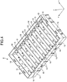
secondary battery cells 5 housed in thelower case 2 with reference toFIG. 3 and a perspective view of thelower case 2 inFIG. 4 . - The
lower case 2 has a plurality offirst walls 13. Thefirst walls 13 oppose theprincipal faces 6b of the adjacentsecondary battery cells 5 and spaced apart from each other with first given spacing substantially equal to the X-directional thickness of thesecondary battery cell 5. Thelower case 2 also has a pair ofsecond walls 14 and abottom part 15. Thesecond walls 14 oppose thelateral faces 6c of thesecondary battery cell 5 and are spaced apart from each other with second given spacing substantially equal to the Y-directional width of thesecondary battery cell 5. Thebottom part 15 opposes thebottom face 6d of thesecondary battery cell 5. Thelower case 2 has an outer circumferential wall provided withfixing holes 16 into which snap fits 31 formed on theupper case 3 are fitted, as described below. - The following describes
deformable ribs 17 and positioningribs 18 of thelower case 2 with reference toFIG. 5 to FIG. 7. FIG. 5 is an XZ sectional view of thelower case 2 provided with thedeformable ribs 17,FIG. 6 is a perspective view of adeformable rib 17, andFIG. 7 is an enlarged view ofFIG. 5 . - As illustrated in
FIG. 5 , thedeformable ribs 17 extend from thebottom part 15 to thefirst walls 13 of thelower case 2. Thedeformable ribs 17 are formed of a synthetic resin material similar to that of thelower case 2 and has a form of triangular pyramid with thefirst wall 13 as one lateral face and thebottom part 15 as a bottom face, for example, as illustrated inFIG. 6 . As illustrated inFIG. 7 , the angle (the letter c inFIG. 6 ) between thebottom part 15 and aridgeline 17a of the triangular pyramid of thedeformable rib 17 is preferably set to 45 degrees or more. The length indicated by the letter a inFIG. 6 , that is, the distance from the intersection between theridgeline 17a of thedeformable rib 17 and thefirst wall 13 to the bottom is preferably set to 2 to 3 mm. The length indicated by the letter b, that is, the distance from the intersection between theridgeline 17a of thedeformable rib 17 and thebottom part 15 to thefirst wall 13 is preferably set to 0.5 to 1.5 mm. However, an appropriate film thickness varies depending on the design of thesecondary battery cell 5 or the cases, therefore, this is not limiting. - The shape of the
deformable ribs 17 is not limited to the triangular pyramid and thedeformable ribs 17 may be optionally shaped as long as the distance from thefirst wall 13 to the end face of thedeformable rib 17 gradually increases in a direction opposite the Z-axial direction (toward the bottom part 15). Meanwhile, thepositioning ribs 18 each have a face parallel to the principal faces 10 or the lateral faces 6c of an exterior container 6. -
FIG. 6 is a sectional view of part of thebottom part 15 of thelower case 2. Herein, thedeformable rib 17 is drawn as a triangle while thepositioning rib 18 is drawn as a rectangle. As illustrated inFIG. 6 , thepositioning ribs 18 are more away from the central part of thesecondary battery cells 5 in the Y-axial direction than thedeformable ribs 17. As illustrated inFIG. 7 , thedeformable ribs 17 are preferably lower in height than thepositioning ribs 18 in the Z-axial direction. Thus, in inserting thesecondary battery cell 5 into thelower case 2, thesecondary battery cell 5 first comes into contact with thepositioning ribs 18 and then with thedeformable ribs 17. That is, the secondary battery cell is corrected in position in the XY plane, and then positioned in the Z direction by thedeformable ribs 17. The secondary battery cell contacts with the ribs in this order, which makes it possible to decrease an amount of deformation of thedeformable ribs 17 to a minimum, and enables thedeformable ribs 17 to appropriately apply a repulsive force to thesecondary battery cell 5. - The
upper case 3 is described next with reference toFIG. 2 andFIG. 8 . Theupper case 3 has a rectangular box shape with a bottom opened and includes atop part 20, a plurality ofthird walls 23, andfourth walls 24. Thethird walls 23 extend with given spacing from one pair of sides of thetop part 20 in a direction substantially orthogonal to the top part. Thefourth walls 24 extend from the other side pair of the bottom part in the direction substantially orthogonal to the bottom part. Thetop part 20 opposes the top of thesecondary battery cell 5. As described above, the part of theupper case 3, corresponding to the positive-electrode terminal 7a and the negative-electrode terminal 7b of thesecondary battery cell 5, is provided withopenings secondary battery cells 5 are housed and assembled in the casing, the positive-electrode terminal 7a and the negative-electrode terminal 7b of eachsecondary battery cell 5 pass through theopenings busbar 12 set on the face of theupper case 3 not opposing thetop face 6a of thesecondary battery cell 5. Theupper case 3 is further provided with a gas exhaust opening 3c at the part corresponding to thegas exhaust valve 8 of thesecondary battery cell 5. The bottom part of the outer circumferential wall of theupper case 3 is provided with the snap fits 31 which fit into the fixing holes 16 of thelower case 2 to couple and fix thelower case 2 and theupper case 3 together. The top part of the outer circumferential wall of theupper case 3 is provided with fixingholes 32. - As illustrated in
FIG. 2 , thelid 4 is also provided with snap fits 41 on the outer circumference. The snap fits 41 fit into the fixing holes of theupper case 3, to couple and fix thelid 4 and theupper case 3 together. Thebattery pack 1 includes aboard 20 that monitors and controls thesecondary battery cells 5, between thelid 4 and theupper case 3, for example. - The
battery pack 1 as above is assembled by the following procedure. - First, the
battery cell 5 is inserted into a space defined by thefirst walls 13, thesecond walls 14, and thebottom part 15 of thelower case 2. Next, theupper case 3 is coupled to thelower case 2 so that the positive-electrode terminal 7a and the negative-electrode terminal 7b of thesecondary battery cell 5 are inserted through theopening 3a and theopening 3b of theupper case 3, respectively. Thebusbar 12 is then set on the face of theupper case 3 not opposing thelower case 2, and the terminal connecting faces of thebusbar 12 are in contact with the positive-electrode terminal 7a and the negative-electrode terminal 7b and connected together by welding, for example. - In assembling the
battery pack 1 by such a procedure, owing to the structure of the present embodiment, thebottom face 6d or the principal faces 10 of thesecondary battery cell 5 come(s) into contact with thepositioning ribs 18 of thelower case 2. Thepositioning ribs 18 differ from thedeformable ribs 17 in having the face parallel to the principal faces 10 or the lateral faces 6c of the exterior container 6. Thus, the insertion of thesecondary battery cell 5 into thelower case 2 does not cause deformation of thepositioning ribs 18. Thereby, thesecondary battery cell 5 is inserted into thelower case 2 in contact with thepositioning ribs 18, whereby thesecondary battery cell 5 is accurately corrected in position in the X-axial direction. - Next, the
secondary battery cell 5 comes into contact with thedeformable ribs 17 lower in position than thepositioning ribs 18 in the Z-axial direction. Thedeformable ribs 17 differ from thepositioning ribs 18 in having the face not parallel to the principal faces 10 or the lateral faces of the exterior container 6. Thedeformable ribs 17 have a triangular pyramid shape with thetop part 20 of theupper case 3 as a bottom face, for example. The shape of thedeformable ribs 17 is not limited to the triangular pyramid, and the deformable ribs may be optionally shaped as long as the distance from thethird wall 23 to the end face of thedeformable rib 17 gradually increases in the Z-axial direction. - The
lower case 2 includes suchdeformable ribs 17 andpositioning ribs 18, so that when inserting thesecondary battery cell 5 into thelower case 2, thesecondary battery cell 5 comes into contact with the face not parallel to the principal faces 10 or the lateral faces 6c of the exterior container 6. This makes it easier for thedeformable ribs 17 to receive the force inserting thesecondary battery cell 5, deforming their contact points. Thereby, thedeformable ribs 17 are crushed in the direction from the open side toward the bottom of thelower case 2. In the case of thedeformable rib 17 with the triangular pyramid shape as above, thesecondary battery cell 5 comes into contact with one side of the triangular pyramid, therefore, thedeformable rib 17 is more easily deformable. In this process, thedeformable rib 17, while deforming, applies a repulsive force to thesecondary battery cell 5 toward the lower case 2 (downward in the Z-axial direction). - In such a state, the
upper case 3 is coupled to thelower case 2 with the snap fits 31, for example. Thedeformable ribs 17 then work to press thesecondary battery cell 5 to theupper case 3 and press thetop face 6a against theupper case 3. Thus, the positive-electrode terminal 7a and the negative-electrode terminal 7b are aligned in the Z-axial direction. In addition, thepositioning ribs 18 serve to fix thesecondary battery cell 5 in an accurate position in the XY plane, so that the positive-electrode terminal 7a and the negative-electrode terminal 7b can be inserted through theopenings upper case 3, respectively. - Thus, the terminal connecting faces of the
busbar 12 are prevented from being misaligned and can contact with and be accurately welded to the positive-electrode terminal 7a and the negative-electrode terminal 7b. - The following describes a first modification with reference to
FIG. 9 . -
FIG. 9 is an XZ sectional view of a housing of thesecondary battery cell 5 surrounded by thefirst walls 13, thesecond walls 14, and thebottom part 15 of thelower case 2. The first modification differs from the embodiment in that thelower case 2 includes aprotrusion 19 in place of thedeformable ribs 17. - As shown in
FIG. 9 , the bottom of thelower case 2 is partially deformed in a direction opposite to thesecondary battery cell 5. Theprotrusion 19 may extend linearly or in a dot form in the Y-axial direction. - When inserted into the
lower case 2 provided with such aprotrusion 19, thebottom face 6d of thesecondary battery cell 5 comes into contact with theprotrusion 19. Theprotrusion 19 is preferably elastic. When inserted into thelower case 2, thebottom face 6d of thesecondary battery cell 5 comes into contact with theprotrusion 19 and then receives a repulsive force toward the upper case 3 (in the Z-axial direction). - In such a state, the
upper case 3 is coupled to thelower case 2 with the snap fits 31, for example. Theprotrusion 19 then presses thesecondary battery cell 5 toward theupper case 3 and presses thetop face 6a against theupper case 3. Thereby, the positive-electrode terminal 7a and the negative-electrode terminal 7b are aligned in the Z-axial direction. In addition, thepositioning ribs 18 work to fix thesecondary battery cell 5 in an accurate position in the XY plane, so that the positive-electrode terminal 7a and the negative-electrode terminal 7b can be inserted through theopenings upper case 3, respectively. - Thus, the terminal connecting faces of the
busbar 12 are prevented from being misaligned, and can contact with the positive-electrode terminal 7a and the negative-electrode terminal 7b and be correctly welded thereto. - The following describes a second modification with reference to
FIG. 10 to FIG. 12 . - In the second modification, the
lower case 2 includes any of anelastic layer 21, an adhesive 22, and theprotrusion 19. - First, the
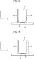
elastic layer 21 is described with reference toFIG. 10. FIG. 10 is an XZ sectional view of a housing of thesecondary battery cell 5 surrounded by thefirst walls 13, thesecond walls 14, and thebottom part 15 of thelower case 2. Theelastic layer 21 is formed in the part surrounded by thefirst walls 13, thesecond walls 14, and thebottom part 15. Theelastic layer 21 contacts with the principal faces 6b or the lateral faces 6c of the exterior container 6 of thebattery cell 5 to support thesecondary battery cell 5. - The
elastic layer 21 generates an elastic force that presses thesecondary battery cell 5. Theelastic layer 21 formed on thebottom part 15 thus exerts a force on thesecondary battery cell 5 in a direction toward the upper case 3 (Z-axial direction). As illustrated inFIG. 10 , theelastic layer 21 may extend along thefirst walls 13. Theelastic layer 21 is made of a foaming synthetic resin material (a foaming material such as foaming urethane). Theelastic layer 21 is porous containing air bubbles, by way of an example. Theelastic layer 21 is formed of a foaming synthetic resin material as an example. To form such anelastic layer 21, the foaming synthetic material is applied to thelower case 2 with a spray nozzle, for example, and subjected to heat. Thereby, the foaming synthetic resin material foams to gain elasticity, and theelastic layer 21 made of elastic synthetic resin material is formed. It is thus possible to easily obtain theelastic layer 21 that supports thesecondary battery cell 5, as an example. - The adhesive 22 is now described with reference to
FIG. 11. FIG. 11 is an XZ sectional view of the housing of thesecondary battery cell 5 surrounded by thefirst walls 13, thesecond walls 14, and thebottom part 15 of thelower case 2. As illustrated inFIG. 11 , the adhesive 22 lies on thebottom part 15 of thelower case 2. Thus, the adhesive 22 applies a repulsive force to thesecondary battery cell 5 in the direction toward the upper case 3 (Z-axial direction). The adhesive 22 may have a film thickness of preferably 0.1 mm to 0.3 mm. However, an appropriate film thickness varies depending on the design of thesecondary battery cell 5 or the cases, therefore, this is not limiting. - The battery pack according to the modification includes an
upper case 3 illustrated inFIG. 12. FIG. 12 is an XZ sectional view of the housing of thesecondary battery cell 5 surrounded by thethird walls 23, thefourth walls 24, and thetop part 20. Theupper case 3 includesdeformable ribs 25 extending from thethird wall 23 to thetop part 20. Thedeformable ribs 25 are formed of a synthetic resin material similar to that of theupper case 3 and have a triangular pyramid shape with thethird wall 23 as one lateral face and thetop part 20 as one lateral face, for example. The angle between thetop part 20 and one side of the triangular pyramid connecting thetop part 20 and thethird wall 23 is preferably set to 45 degrees or more. The shape of thedeformable ribs 25 is not limited to the triangular pyramid and may be optionally shaped as long as they include a face not parallel to the principal faces 10 or the lateral faces 6c of the exterior container 6 of thesecondary battery cell 5. - Owing to such a configuration and structure, in assembling the battery pack by the procedure illustrated in the embodiment, the
bottom face 6d of thesecondary battery cell 5, while inserted into thelower case 2, receives a repulsive force toward the upper case 3 (in the Z-axial direction) from theelastic layer 21, the adhesive 22, or theprotrusion 19 of thelower case 2. In coupling theupper case 3 to thelower case 2 with the snap fits 31 in such a state, for example, thesecondary battery cell 5 is pressed by theelastic layer 21, the adhesive 22, or theprotrusion 19 toward theupper case 3, and thetop face 6a is pressed against theupper case 3. Thereby, the positive-electrode terminal 7a and the negative-electrode terminal 7b are aligned in the Z-axial direction. In addition, thedeformable ribs 25 of theupper case 3 come into contact with thetop face 6a of thesecondary battery cell 5, and are deformed, thereby enabling positional correction in the XY plane. - Consequently, the positive-
electrode terminal 7a and the negative-electrode terminal 7b can be inserted through theopenings upper case 3, respectively. - Thereby, the terminal connecting faces of the
busbar 12 are prevented from being misaligned and can contact with the positive-electrode terminal 7a and the negative-electrode terminal 7b and be correctly welded thereto. - The
secondary battery cell 5 is vertically secured by theelastic layer 21, the adhesive 22, or theprotrusion 19 of thelower case 2 and thedeformable ribs 25 of theupper case 3. That is, thesecondary battery cell 5 can be more stably secured inside the battery pack. - In addition to the features as above, the
secondary battery cell 5 can be more stably secured inside the battery pack by applying an adhesive to thetop face 6a of theupper case 3. - A third modification is now described with reference to
FIG. 8 . The third modification has the same structure as the second modification except for part of theupper case 3. - In the third modification, the
upper case 3 are provided withchannels 26 at part of thetop part 20 adjacent to thethird walls 23. Thechannels 26 extend in the Y-axial direction along thethird walls 23. As illustrated inFIG. 8 , it is preferable to provide thechannels 26 at parts located between theopenings top part 20 of theupper case 3. However, this is not limiting. The depth of thechannels 26 is preferably set to 0.1 mm to 0.3 mm; however, this is not limiting. - If the
upper case 3 is coated with an adhesive for fixation of thesecondary battery cell 5, anexcessive adhesive 22 flows into thechannels 26 when thesecondary battery cell 5 contacts with thetop part 20 of theupper case 3 for assembly of the battery pack. Theexcessive adhesive 22 is accumulated and hardened between thetop part 20 of theupper case 3 and thesecondary battery cell 5. This can reduce the possibility of misaligning thesecondary battery cell 5 in the Z-axial direction. It is thus possible to lower the possibility of misaligning the positive-electrode terminal 7a and the negative-electrode terminal 7b of thesecondary battery cell 5, and lower the possibility of improperly welding the busbar to the terminals. - Another modification is described with reference to
FIG. 13. FIG. 13 is a partial enlarged view of an XZ section of theupper case 3. The present modification has the same structure as the second modification except for part of theupper case 3. - In this modification, the
deformable ribs 25 are located insecond channels 27 in thetop part 20 of theupper case 3. Thesecond channels 27 extend adjacent to thethird walls 23. Thetop face 6a of thesecondary battery cell 5, when housed in theupper case 3, abuts on thetop part 20 of theupper case 3 with nosecond channels 27 formed. In other words, thetop face 6a abuts on a protrusion defined between thesecond channels 27 by thesecond channels 27 of thetop part 20. - In such a structure, when the
secondary battery cell 5 is placed in theupper case 3 for assembly of the battery pack, thedeformable ribs 25 are deformed by thesecondary battery cell 5. In this process, thedeformable ribs 25 deform inside thesecond channels 27. By thedeformed ribs 25, thus, thesecondary battery cell 5 can be accurately corrected in position in the XY plane with no change in the Z-axial height of thesecondary battery cell 5. - A next modification is described with reference to
FIG. 14. FIG. 14 is an XY sectional view of thethird walls 23 and thedeformable rib 25 of theupper case 3. This modification has the same structure as the second modification except for part of theupper case 3. - In this modification, the
third walls 23 of theupper case 3 are provided withslits 28 at a part adjacent to thedeformable rib 25. Thedeformable rib 25 is preferably interposed between theadjacent slits 28. - In such a structure, when the
secondary battery cell 5 is placed in theupper case 3 for assembly of the battery pack, thedeformable ribs 25 are deformed by thesecondary battery cell 5. In this process, due to theslits 28, thedeformable ribs 25 fall down away from the secondary battery cell 5 (in X-axial direction, for example) together with thethird walls 23 including thedeformable ribs 25. This can eliminate misalignment of thesecondary battery cell 5 or theupper case 3. Theslits 28 may pass through thethird walls 23 to be able to eliminate larger misalignment. However, theslits 28 may not pass therethrough. - Further,
FIG. 15 is a sectional view of part of thelower case 2 anddeformable ribs 17.FIG. 15 illustrates thelower case 2 of the battery pack when installed, with upper faces in upper position and lower faces in lower position. As illustrated inFIG. 15 , thedeformable ribs 17 are located asymmetric to the wall surfaces. The lower faces are provided with a larger number ofdeformable ribs 17. By such a structure, the lower faces receiving a larger load are provided with a larger number ofdeformable ribs 17, which can more stably secure thesecondary battery cells 5. - While certain embodiments have been described, these embodiments have been presented by way of example only, and are not intended to limit the scope of the inventions. Indeed, the novel embodiments described herein may be embodied in a variety of other forms; furthermore, various omissions, substitutions and changes in the form of the embodiments described herein may be made without departing from the spirit of the inventions. The accompanying claims and their equivalents are intended to cover such forms or modifications as would fall within the scope and spirit of the inventions.
-
- 1
- BATTERY PACK
- 2
- LOWER CASE
- 3
- UPPER CASE
- 3c
- GAS EXHAUST OPENING
- 4
- LID
- 5
- SECONDARY BATTERY CELL
- 6
- EXTERIOR CONTAINER
- 6a
- TOP FACE
- 6b
- PRINCIPAL FACE
- 6c
- LATERAL FACE
- 6d
- BOTTOM FACE
- 7a
- POSITIVE-ELECTRODE TERMINAL
- 7b
- NEGATIVE-ELECTRODE TERMINAL
- 10
- PRINCIPAL FACE
- 12
- BUSBAR
- 13
- FIRST WALL
- 14
- SECOND WALL
- 15
- BOTTOM PART
- 16
- FIXING HOLE
- 17
- DEFORMABLE RIB
- 17a
- RIDGELINE
- 18
- RIB
- 19
- PROTRUSION
- 20
- BOARD
- 20
- TOP FACE
- 21
- ELASTIC LAYER
- 22
- ADHESIVE
- 23
- THIRD WALL
- 24
- FOURTH WALL
- 25
- DEFORMABLE RIB
- 26
- CHANNEL
- 27
- SECOND CHANNEL
- 28
- SLIT
Claims (10)
- A battery pack comprising:a lower case having a rectangular box shape with a top opened, the lower case including:a bottom part,a plurality of first walls extending from the bottom part in a direction substantially orthogonal to the bottom part with given spacing from one pair of sides of the bottom part, andsecond walls extending from the other pair of sides of the bottom part in the direction substantially orthogonal to the bottom part;an upper case having a rectangular box shape with a bottom opened, the upper case including a top part opposing the lower case; anda plurality of secondary batteries each including:a top face provided with a positive-electrode terminal and a negative-electrode terminal,a pair of principal faces extending from a pair of long sides of the top face in a direction substantially orthogonal to the top face,a pair of lateral faces extending between the principal faces, anda bottom face opposing the top face, the secondary batteries being housed between the first walls of the lower case such that the bottom faces oppose the bottom part, whereinthe lower case comprises deformable ribs extending from the bottom part to the first walls, the deformable ribs being partially crushed in a direction from an open side toward the bottom part of the lower case.
- A battery pack comprising:a lower case having a rectangular box shape with a top opened, the lower case includinga bottom part,a plurality of first walls extending from the bottom part in a direction substantially orthogonal to the bottom part with given spacing from one pair of sides of the bottom part, andsecond walls extending from the other pair of sides of the bottom part in the direction substantially orthogonal to the bottom part;an upper case having a rectangular box shape with a bottom opened, the upper case including a top part opposing the lower case; anda plurality of secondary batteries each includinga top face provided with a positive-electrode terminal and a negative-electrode terminal,a pair of principal faces extending from a pair of long sides of the top face in a direction substantially orthogonal to the top face,a pair of lateral faces extending between the principal faces, anda bottom face opposing the top face, the secondary batteries being housed between the first walls of the lower case such that the bottom faces oppose the bottom part, whereinthe lower case comprises positioning ribs extending from the bottom part to the first walls or the second walls.
- A battery pack comprising:a lower case having a rectangular box shape with a top opened, the lower case includinga bottom part,a plurality of first walls extending from the bottom part in a direction substantially orthogonal to the bottom part with given spacing from one pair of sides of the bottom part, andsecond walls extending from the other pair of sides of the bottom part in the direction substantially orthogonal to the bottom part;an upper case having a rectangular box shape with a bottom opened, the upper case including a top part opposing the lower case; anda plurality of secondary batteries each includinga top face provided with a positive-electrode terminal and a negative-electrode terminal,a pair of principal faces extending from a pair of long sides of the top face in a direction substantially orthogonal to the top face,a pair of lateral faces extending between the principal faces, anda bottom face opposing the top face, the secondary batteries being housed between the first walls of the lower case such that the bottom faces oppose the bottom part, whereinthe lower case comprises:deformable ribs that extend from the bottom part to the first walls and are partially crushed in a direction from an open side toward the bottom part of the lower case, andpositioning ribs that extend from the bottom part to the first walls or the second walls and are located further away from a central part of the secondary battery than the deformable ribs.
- The battery pack according to any one of claims 1 to 3, wherein
the lower case further comprises a protrusion in the bottom part. - The battery pack according to any one of claims 1 to 4, further comprising
a busbar being set on the top part of the upper case not opposing the top face of the secondary battery, the busbar that connects the positive-electrode terminal or the negative-electrode terminal. - A battery pack comprising:a lower case having a rectangular box shape with a top opened, the lower case includinga bottom part,a plurality of first walls extending from the bottom part in a direction substantially orthogonal to the bottom part with given spacing from one pair of sides of the bottom part, andsecond walls extending from the other pair of sides of the bottom part in the direction substantially orthogonal to the bottom part;an upper case having a rectangular box shape with a bottom opened, the upper case including:a top part opposing the lower case,a plurality of third walls extending from the top part in a direction substantially orthogonal to the top part with given spacing from one pair of sides of the top part, andfourth walls extending from the other pair of sides of the top part in the direction substantially orthogonal to the top part; anda plurality of secondary batteries each includinga top face provided with a positive-electrode terminal and a negative-electrode terminal,a pair of principal faces extending from a pair of long sides of the top face in a direction substantially orthogonal to the top face,a pair of lateral faces extending between the principal faces, anda bottom face opposing the top face, the secondary batteries being housed between the first walls of the lower case such that the bottom faces oppose the bottom part between the first walls of the lower case and the top faces oppose the top part between the third walls of the upper case, whereinthe upper case comprises deformable ribs that extend from the top part to the third walls, and is partially crushed in a direction from an open side toward the top part of the upper case, andthe lower case comprises positioning ribs extending from the bottom part to the first walls or the second walls.
- The battery pack according to claim 6, wherein
the lower case comprises an elastic layer on the bottom part. - The battery pack according to claim 7, wherein
the elastic layer contains a foaming synthetic resin material. - The battery pack according to any one of claims 6 to 8, wherein
part of the top part of the upper case adjacent to the third walls are provided with a channel in the direction from an open side toward the top part of the upper case, and
the deformable ribs are located in the channel. - The battery pack according to any one of claims 6 to 9, further comprising
a busbar being set on the top part of the upper case not opposing the top face of the secondary battery, the busbar that connects the positive-electrode terminal or the negative-electrode terminal.
Applications Claiming Priority (2)
| Application Number | Priority Date | Filing Date | Title |
|---|---|---|---|
| JP2018030847A JP2019145459A (en) | 2018-02-23 | 2018-02-23 | Battery pack |
| PCT/JP2019/006452 WO2019163864A1 (en) | 2018-02-23 | 2019-02-21 | Assembled battery |
Publications (2)
| Publication Number | Publication Date |
|---|---|
| EP3758088A1 true EP3758088A1 (en) | 2020-12-30 |
| EP3758088A4 EP3758088A4 (en) | 2022-02-23 |
Family
ID=67687691
Family Applications (1)
| Application Number | Title | Priority Date | Filing Date |
|---|---|---|---|
| EP19758229.9A Pending EP3758088A4 (en) | 2018-02-23 | 2019-02-21 | BATTERY ASSEMBLY |
Country Status (5)
| Country | Link |
|---|---|
| US (1) | US20200381683A1 (en) |
| EP (1) | EP3758088A4 (en) |
| JP (1) | JP2019145459A (en) |
| CN (1) | CN111771294B (en) |
| WO (1) | WO2019163864A1 (en) |
Families Citing this family (11)
| Publication number | Priority date | Publication date | Assignee | Title |
|---|---|---|---|---|
| EP3799195A1 (en) * | 2019-09-27 | 2021-03-31 | Proterra Inc. | Battery cassette |
| JP7542962B2 (en) * | 2020-02-10 | 2024-09-02 | 本田技研工業株式会社 | Power storage device |
| JP7537885B2 (en) * | 2020-03-02 | 2024-08-21 | トヨタ自動車株式会社 | Battery Module |
| US11594778B2 (en) * | 2020-03-04 | 2023-02-28 | Damon Motors Inc. | Cell holder with intermediate tray |
| US20230066160A1 (en) * | 2020-03-04 | 2023-03-02 | Damon Motors Inc. | Battery pack enclosure with vent |
| KR102927430B1 (en) * | 2020-05-29 | 2026-02-12 | 삼성에스디아이 주식회사 | Rechargeable battery |
| EP4064431A4 (en) * | 2020-06-16 | 2023-11-29 | LG Energy Solution, Ltd. | BATTERY, ELECTRONIC DEVICE INCLUDING SAME, AND VEHICLE |
| KR102676194B1 (en) * | 2020-09-28 | 2024-06-19 | 주식회사 엘지에너지솔루션 | Packaging box for battery pack and battery pack housed in the same |
| JP7232802B2 (en) * | 2020-10-20 | 2023-03-03 | プライムプラネットエナジー&ソリューションズ株式会社 | power storage device |
| JP7348930B2 (en) * | 2021-07-06 | 2023-09-21 | プライムプラネットエナジー&ソリューションズ株式会社 | Energy storage module |
| JP7740219B2 (en) * | 2022-12-07 | 2025-09-17 | 株式会社デンソー | Battery modules and battery stacks |
Family Cites Families (9)
| Publication number | Priority date | Publication date | Assignee | Title |
|---|---|---|---|---|
| US6376126B1 (en) * | 1999-10-13 | 2002-04-23 | Johnson Controls Technology Company | Composite battery container with integral flexible ribs |
| JP2003068260A (en) | 2001-08-27 | 2003-03-07 | Sanyo Electric Co Ltd | Battery pack |
| JP3848565B2 (en) * | 2001-11-27 | 2006-11-22 | 松下電器産業株式会社 | Battery connection structure, battery module, and battery pack |
| JP6049276B2 (en) * | 2012-03-14 | 2016-12-21 | 株式会社東芝 | Secondary battery device |
| WO2013140800A1 (en) * | 2012-03-21 | 2013-09-26 | 株式会社リチウムエナジージャパン | Power source device and positioning tray |
| JP6036095B2 (en) * | 2012-09-26 | 2016-11-30 | 株式会社Gsユアサ | Assembled battery |
| JP6191201B2 (en) * | 2013-03-29 | 2017-09-06 | 株式会社Gsユアサ | Power storage device |
| JP2015018790A (en) * | 2013-06-14 | 2015-01-29 | 株式会社Gsユアサ | Power storage module |
| JP2017079130A (en) * | 2015-10-20 | 2017-04-27 | 株式会社東芝 | Battery module |
-
2018
- 2018-02-23 JP JP2018030847A patent/JP2019145459A/en active Pending
-
2019
- 2019-02-21 WO PCT/JP2019/006452 patent/WO2019163864A1/en not_active Ceased
- 2019-02-21 US US16/971,633 patent/US20200381683A1/en not_active Abandoned
- 2019-02-21 EP EP19758229.9A patent/EP3758088A4/en active Pending
- 2019-02-21 CN CN201980014492.0A patent/CN111771294B/en active Active
Also Published As
| Publication number | Publication date |
|---|---|
| JP2019145459A (en) | 2019-08-29 |
| US20200381683A1 (en) | 2020-12-03 |
| CN111771294B (en) | 2022-12-27 |
| CN111771294A (en) | 2020-10-13 |
| WO2019163864A1 (en) | 2019-08-29 |
| EP3758088A4 (en) | 2022-02-23 |
Similar Documents
| Publication | Publication Date | Title |
|---|---|---|
| EP3758088A1 (en) | Assembled battery | |
| CN106711366B (en) | Rechargeable battery module | |
| US10003054B2 (en) | Power source pack | |
| CN106450407B (en) | Secondary battery | |
| EP2390943B1 (en) | Battery housing device | |
| JPWO2020166182A1 (en) | Battery module | |
| WO2019031175A1 (en) | Battery pack and production method therefor | |
| CN110998908B (en) | Restraint member and battery module | |
| US20210367290A1 (en) | Battery pack | |
| US12199308B2 (en) | Bus bar plate | |
| CN117134060A (en) | Batteries and methods of manufacturing batteries | |
| JP2019160736A (en) | Connection module, and power storage module | |
| US11502361B2 (en) | Energy storage apparatus | |
| JP6107813B2 (en) | Power supply | |
| WO2020026966A1 (en) | Cell module fixing structure | |
| JP2019169386A (en) | Power storage device | |
| JP7788882B2 (en) | Battery Module | |
| US20200176738A1 (en) | Energy storage apparatus | |
| EP3518319A1 (en) | Battery pack and electrically conductive member | |
| EP4358240A1 (en) | Battery module | |
| EP4358247A1 (en) | Battery module | |
| JP6287705B2 (en) | Power storage device | |
| US20250183453A1 (en) | Energy storage apparatus | |
| US12341220B2 (en) | Energy storage apparatus | |
| WO2022254931A1 (en) | Power storage device |
Legal Events
| Date | Code | Title | Description |
|---|---|---|---|
| STAA | Information on the status of an ep patent application or granted ep patent |
Free format text: STATUS: THE INTERNATIONAL PUBLICATION HAS BEEN MADE |
|
| PUAI | Public reference made under article 153(3) epc to a published international application that has entered the european phase |
Free format text: ORIGINAL CODE: 0009012 |
|
| STAA | Information on the status of an ep patent application or granted ep patent |
Free format text: STATUS: REQUEST FOR EXAMINATION WAS MADE |
|
| 17P | Request for examination filed |
Effective date: 20200821 |
|
| AK | Designated contracting states |
Kind code of ref document: A1 Designated state(s): AL AT BE BG CH CY CZ DE DK EE ES FI FR GB GR HR HU IE IS IT LI LT LU LV MC MK MT NL NO PL PT RO RS SE SI SK SM TR |
|
| AX | Request for extension of the european patent |
Extension state: BA ME |
|
| DAV | Request for validation of the european patent (deleted) | ||
| DAX | Request for extension of the european patent (deleted) | ||
| RIC1 | Information provided on ipc code assigned before grant |
Ipc: H01M 50/502 20210101ALI20211013BHEP Ipc: H01M 50/291 20210101ALI20211013BHEP Ipc: H01M 50/238 20210101ALI20211013BHEP Ipc: H01M 50/209 20210101AFI20211013BHEP |
|
| REG | Reference to a national code |
Ref country code: DE Ref legal event code: R079 Free format text: PREVIOUS MAIN CLASS: H01M0002100000 Ipc: H01M0050209000 |
|
| A4 | Supplementary search report drawn up and despatched |
Effective date: 20220124 |
|
| RIC1 | Information provided on ipc code assigned before grant |
Ipc: H01M 50/502 20210101ALI20220118BHEP Ipc: H01M 50/291 20210101ALI20220118BHEP Ipc: H01M 50/238 20210101ALI20220118BHEP Ipc: H01M 50/209 20210101AFI20220118BHEP |
|
| STAA | Information on the status of an ep patent application or granted ep patent |
Free format text: STATUS: EXAMINATION IS IN PROGRESS |
|
| 17Q | First examination report despatched |
Effective date: 20241127 |