EP3758086A1 - Large-capacity unit cell - Google Patents
Large-capacity unit cell Download PDFInfo
- Publication number
- EP3758086A1 EP3758086A1 EP19200881.1A EP19200881A EP3758086A1 EP 3758086 A1 EP3758086 A1 EP 3758086A1 EP 19200881 A EP19200881 A EP 19200881A EP 3758086 A1 EP3758086 A1 EP 3758086A1
- Authority
- EP
- European Patent Office
- Prior art keywords
- cover
- negative electrode
- positive electrode
- electrode group
- electrode
- Prior art date
- Legal status (The legal status is an assumption and is not a legal conclusion. Google has not performed a legal analysis and makes no representation as to the accuracy of the status listed.)
- Granted
Links
Images

Classifications
-
- H—ELECTRICITY
- H01—ELECTRIC ELEMENTS
- H01M—PROCESSES OR MEANS, e.g. BATTERIES, FOR THE DIRECT CONVERSION OF CHEMICAL ENERGY INTO ELECTRICAL ENERGY
- H01M10/00—Secondary cells; Manufacture thereof
- H01M10/04—Construction or manufacture in general
- H01M10/0431—Cells with wound or folded electrodes
-
- H—ELECTRICITY
- H01—ELECTRIC ELEMENTS
- H01M—PROCESSES OR MEANS, e.g. BATTERIES, FOR THE DIRECT CONVERSION OF CHEMICAL ENERGY INTO ELECTRICAL ENERGY
- H01M50/00—Constructional details or processes of manufacture of the non-active parts of electrochemical cells other than fuel cells, e.g. hybrid cells
- H01M50/20—Mountings; Secondary casings or frames; Racks, modules or packs; Suspension devices; Shock absorbers; Transport or carrying devices; Holders
- H01M50/218—Mountings; Secondary casings or frames; Racks, modules or packs; Suspension devices; Shock absorbers; Transport or carrying devices; Holders characterised by the material
- H01M50/22—Mountings; Secondary casings or frames; Racks, modules or packs; Suspension devices; Shock absorbers; Transport or carrying devices; Holders characterised by the material of the casings or racks
- H01M50/227—Organic material
-
- H—ELECTRICITY
- H01—ELECTRIC ELEMENTS
- H01M—PROCESSES OR MEANS, e.g. BATTERIES, FOR THE DIRECT CONVERSION OF CHEMICAL ENERGY INTO ELECTRICAL ENERGY
- H01M10/00—Secondary cells; Manufacture thereof
- H01M10/60—Heating or cooling; Temperature control
- H01M10/65—Means for temperature control structurally associated with the cells
- H01M10/655—Solid structures for heat exchange or heat conduction
- H01M10/6551—Surfaces specially adapted for heat dissipation or radiation, e.g. fins or coatings
-
- H—ELECTRICITY
- H01—ELECTRIC ELEMENTS
- H01M—PROCESSES OR MEANS, e.g. BATTERIES, FOR THE DIRECT CONVERSION OF CHEMICAL ENERGY INTO ELECTRICAL ENERGY
- H01M50/00—Constructional details or processes of manufacture of the non-active parts of electrochemical cells other than fuel cells, e.g. hybrid cells
- H01M50/20—Mountings; Secondary casings or frames; Racks, modules or packs; Suspension devices; Shock absorbers; Transport or carrying devices; Holders
- H01M50/204—Racks, modules or packs for multiple batteries or multiple cells
- H01M50/207—Racks, modules or packs for multiple batteries or multiple cells characterised by their shape
- H01M50/213—Racks, modules or packs for multiple batteries or multiple cells characterised by their shape adapted for cells having curved cross-section, e.g. round or elliptic
-
- H—ELECTRICITY
- H01—ELECTRIC ELEMENTS
- H01M—PROCESSES OR MEANS, e.g. BATTERIES, FOR THE DIRECT CONVERSION OF CHEMICAL ENERGY INTO ELECTRICAL ENERGY
- H01M50/00—Constructional details or processes of manufacture of the non-active parts of electrochemical cells other than fuel cells, e.g. hybrid cells
- H01M50/20—Mountings; Secondary casings or frames; Racks, modules or packs; Suspension devices; Shock absorbers; Transport or carrying devices; Holders
- H01M50/262—Mountings; Secondary casings or frames; Racks, modules or packs; Suspension devices; Shock absorbers; Transport or carrying devices; Holders with fastening means, e.g. locks
-
- H—ELECTRICITY
- H01—ELECTRIC ELEMENTS
- H01M—PROCESSES OR MEANS, e.g. BATTERIES, FOR THE DIRECT CONVERSION OF CHEMICAL ENERGY INTO ELECTRICAL ENERGY
- H01M50/00—Constructional details or processes of manufacture of the non-active parts of electrochemical cells other than fuel cells, e.g. hybrid cells
- H01M50/20—Mountings; Secondary casings or frames; Racks, modules or packs; Suspension devices; Shock absorbers; Transport or carrying devices; Holders
- H01M50/271—Lids or covers for the racks or secondary casings
-
- H—ELECTRICITY
- H01—ELECTRIC ELEMENTS
- H01M—PROCESSES OR MEANS, e.g. BATTERIES, FOR THE DIRECT CONVERSION OF CHEMICAL ENERGY INTO ELECTRICAL ENERGY
- H01M50/00—Constructional details or processes of manufacture of the non-active parts of electrochemical cells other than fuel cells, e.g. hybrid cells
- H01M50/30—Arrangements for facilitating escape of gases
-
- H—ELECTRICITY
- H01—ELECTRIC ELEMENTS
- H01M—PROCESSES OR MEANS, e.g. BATTERIES, FOR THE DIRECT CONVERSION OF CHEMICAL ENERGY INTO ELECTRICAL ENERGY
- H01M50/00—Constructional details or processes of manufacture of the non-active parts of electrochemical cells other than fuel cells, e.g. hybrid cells
- H01M50/50—Current conducting connections for cells or batteries
- H01M50/528—Fixed electrical connections, i.e. not intended for disconnection
-
- Y—GENERAL TAGGING OF NEW TECHNOLOGICAL DEVELOPMENTS; GENERAL TAGGING OF CROSS-SECTIONAL TECHNOLOGIES SPANNING OVER SEVERAL SECTIONS OF THE IPC; TECHNICAL SUBJECTS COVERED BY FORMER USPC CROSS-REFERENCE ART COLLECTIONS [XRACs] AND DIGESTS
- Y02—TECHNOLOGIES OR APPLICATIONS FOR MITIGATION OR ADAPTATION AGAINST CLIMATE CHANGE
- Y02E—REDUCTION OF GREENHOUSE GAS [GHG] EMISSIONS, RELATED TO ENERGY GENERATION, TRANSMISSION OR DISTRIBUTION
- Y02E60/00—Enabling technologies; Technologies with a potential or indirect contribution to GHG emissions mitigation
- Y02E60/10—Energy storage using batteries
-
- Y—GENERAL TAGGING OF NEW TECHNOLOGICAL DEVELOPMENTS; GENERAL TAGGING OF CROSS-SECTIONAL TECHNOLOGIES SPANNING OVER SEVERAL SECTIONS OF THE IPC; TECHNICAL SUBJECTS COVERED BY FORMER USPC CROSS-REFERENCE ART COLLECTIONS [XRACs] AND DIGESTS
- Y02—TECHNOLOGIES OR APPLICATIONS FOR MITIGATION OR ADAPTATION AGAINST CLIMATE CHANGE
- Y02P—CLIMATE CHANGE MITIGATION TECHNOLOGIES IN THE PRODUCTION OR PROCESSING OF GOODS
- Y02P70/00—Climate change mitigation technologies in the production process for final industrial or consumer products
- Y02P70/50—Manufacturing or production processes characterised by the final manufactured product
Definitions
- the present invention relates to the field of battery technologies, and in particular to a large-capacity unit cell.
- the power batteries may be classified into three types: a cylindrical type, a prismatic type, and a pouch type. Cylindrical batteries have been applied to many vehicle models due to their long development time, great advantages in consistency, and their mature manufacturing processes and low costs.
- an electrode group of a cylindrical battery is of a wound type.
- electrode sheets and a separator are wound around the winding core of a winder, and after a winding radius is reached, an electrode group formed by winding the electrode sheets and the separator is pulled from the winding core for battery assembly.
- the winding radius of the electrode group is always relatively small, that is, the total length of electrode sheets is always relatively short, and the length of an electrode sheet is proportional to the capacity of a battery, such that the capacity of the unit cell with the wound-type electrode group is usually relatively small.
- the objective of the present invention is to provide a large-capacity unit cell, to alleviate the technical problem in the prior art that the capacity of a unit cell with a wound-type electrode group is relatively small.
- the large-capacity unit cell provided in the present invention comprises a base body provided with a plurality of accommodation cavities, each of the accommodation cavity being provided with an electrode group module, wherein the electrode group modules are connected in parallel; and the electrode group module comprises a central shaft and an electrode group wound around the central shaft, the electrode group comprises a positive electrode sheet, a negative electrode sheet and a separator, and the separator is used to separate the positive electrode sheet from the negative electrode sheet.
- the accommodation cavity passes through the base body, and a positive electrode terminal and a negative electrode terminal of the electrode group module are respectively located at two ends of the accommodation cavity; and the electrode group module further comprises a positive electrode cover and a negative electrode cover, the positive electrode cover covers a positive electrode terminal of the electrode group, the negative electrode cover covers a negative electrode terminal of the electrode group, and the positive electrode cover and the negative electrode cover are both fixedly connected to the base body.
- two electrode group modules are provided, the two electrode group modules are connected in parallel, and are placed in the same direction in the accommodation cavity; and the positive electrode covers of the two electrode group modules are of an integral structure, and the negative electrode covers of the two electrode group modules are of an integral structure.
- the electrode group module further comprises a positive electrode terminal cover and a negative electrode terminal cover, the positive electrode terminal cover is arranged between the positive electrode cover and the positive electrode terminal of the electrode group, and the negative electrode terminal cover is arranged between the negative electrode cover and the negative electrode terminal of the electrode group; the positive electrode terminal cover is fixedly connected to the positive electrode cover, and is connected to the central shaft in an insulated manner; and the negative electrode terminal cover is fixedly connected to the negative electrode cover, and is connected to the central shaft in an insulated manner.
- the positive electrode terminal cover is connected to the central shaft by means of a first threaded fastener, and an insulating part is arranged between the first threaded fastener and the positive electrode terminal cover; and/or the negative electrode terminal cover is connected to the central shaft by means of a first threaded fastener, and an insulating part is arranged between the first threaded fastener and the negative electrode terminal cover.
- the electrode group module further comprises a positive electrode tab and a negative electrode tab, the positive electrode tab is arranged between the positive electrode terminal cover and the positive electrode terminal of the electrode group, and the negative electrode tab is arranged between the negative electrode terminal cover and the negative electrode terminal of the electrode group; the positive electrode tab is fixedly connected to the positive electrode terminal cover, and is connected to the central shaft in an insulated manner; and the negative electrode tab is fixedly connected to the negative electrode terminal cover, and is connected to the central shaft in an insulated manner.
- a first heat dissipation rib is arranged outside the positive electrode cover, and a second heat dissipation rib is arranged outside the negative electrode cover.
- the base body is rectangular, the accommodation cavity is a through hole, and an axial direction of the through hole is consistent with a height direction of the base body.
- a third heat dissipation rib is arranged on an outer side wall of the base body.
- the base body is provided with a safety valve, and the safety valve is used to discharge gas in the accommodation cavity.
- the large-capacity unit cell provided in the present invention can achieve the following beneficial effects:
- the large-capacity unit cell provided in the present invention comprises a base body for accommodation and installation of all components, wherein the base body is provided with a plurality of accommodation cavities, each of the accommodation cavities is provided with an electrode group module, and the electrode group modules are connected in parallel; and the electrode group module comprises an electrode group and a central shaft for the electrode group to be wound around, and the electrode group comprises a positive electrode sheet, a negative electrode sheet, and a separator for separating the positive electrode sheet from the negative electrode sheet.
- the positive electrode sheet, the negative electrode sheet, and the separator are wound around the central shaft, and after a winding radius meets the requirement, the electrode sheets and the separator do not need to be pulled from the central shaft, wherein as a constituent part of the electrode group, the central shaft is used for the production of the large-capacity unit cell. Because the wound electrode sheets and the separator do not need to be pulled from the central shaft, electrode sheets at layers and two sides of the separator can keep good uniformity, and the case where the separator inside the electrode group is damaged due to a pull can also be reduced.
- the above two points can both greatly reduce a potential security hazard that a short circuit occurs inside the electrode group of the large-capacity unit cell, so that the winding radius of the electrode group of the large-capacity cell is increased and the length of an electrode sheet is increased, thereby making the capacity of the large-capacity unit cell relatively large.
- This embodiment provides a large-capacity unit cell, comprising a base body 100 provided with a plurality of accommodation cavities 110, each of the accommodation cavities 110 being provided with an electrode group module 200, wherein the electrode group modules 200 are connected in parallel; and the electrode group module 200 comprises a central shaft 280 and an electrode group 210 wound around the central shaft 280, the electrode group 210 comprises a positive electrode sheet, a negative electrode sheet and a separator, and the separator is used to separate the positive electrode sheet from the negative electrode sheet.
- the large-capacity unit cell provided in this embodiment comprises a base body 100 for accommodation and installation of all components, wherein the base body 100 is provided with a plurality of accommodation cavities 110, each of the accommodation cavities 110 is provided with an electrode group module 200, and the electrode group modules 200 are connected in parallel; and the electrode group module 200 comprises an electrode group 210, the electrode group module 200 comprises the electrode group 210 and a central shaft 280 for the electrode group 210 to be wound around, and the electrode group 210 comprises a positive electrode sheet, a negative electrode sheet, and a separator used to separate the positive electrode sheet from the negative electrode sheet.
- the positive electrode sheet, the negative electrode sheet, and the separator are wound around the central shaft 280, and after a winding radius meet the requirement, the electrode sheets and the separator do not need to be pulled from the central shaft 280, wherein as a constituent part of the electrode group 210, the central shaft 280 is used for the production of the large-capacity unit cell. Because the wound electrode sheets and the separator do not need to be pulled from the central shaft 280, electrode sheets at layers and two sides of the separator can keep good uniformity, and the case where the separator inside the electrode group 210 is damaged due to a pull can also be reduced.
- the above two points can both greatly reduce a potential security hazard that a short circuit occurs inside the electrode group 210 of the large-capacity unit cell, so that the winding radius of the electrode group 210 of the large-capacity cell is increased and the length of an electrode sheet is increased, thereby making the capacity of the large-capacity unit cell relatively large.
- the electrode group modules 200 may be connected in parallel, and may also be connected in other manners.
- a discharging current of the large-capacity unit cell is increased, so that the capacity of the cell is improved;
- the electrode group modules 200 are connected in series, the voltage of the large-capacity unit cell is increased, and for the same load, a discharging duration of the large-capacity unit cell is increased;
- the electrode group modules 200 of the large-capacity unit cell may also be connected in a hybrid manner, so as to comprehensively use the above-mentioned two manners to improve the capacity and voltage of the cell.
- the large-capacity unit cell has a production process that is simplified, and can effectively avoid the occurrence of a short circuit when the ordinary unit cells are externally connected.
- the accommodation cavity 110 may pass through the base body 100, and the positive electrode terminal and the negative electrode terminal of the electrode group module 200 are respectively located at the two ends of the accommodation cavity 110; and the electrode group module 200 further comprises a positive electrode cover 220 and a negative electrode cover 230, the positive electrode cover 220 covers a positive electrode terminal of the electrode group 210, the negative electrode cover 230 covers a negative electrode terminal of the electrode group 210, and the positive electrode cover 220 and the negative electrode cover 230 are both fixedly connected to the base body 100.
- the positive electrode terminal and the negative electrode terminal of the electrode group module 200 are respectively located at the two ends of the accommodation cavity 110, which effectively reduces the occurrence of a short circuit of the positive electrode terminal and the negative electrode terminal, and reduces the potential security hazard.
- the positive electrode terminal and the negative electrode terminal of the large-capacity unit cell are respectively located at the two opposite ends of the base body 100, and heat generated inside the cell may be conducted away and dissipated from the two ends, thereby improving the heat dissipation performance of the large-capacity unit cell.
- the positive electrode cover 220 and the positive electrode terminal of the electrode group 210, and the negative electrode cover 230 and the negative electrode terminal of the electrode group 210 are both connected in a surface contact manner, so that the internal resistance of the large-capacity unit cell is relatively small, and thus the amount of heat generated inside the large-capacity unit cell is relatively small, and because the internal resistance is relatively small, the heat dissipation speed of the large-capacity unit cell is relatively fast, and the heat dissipation performance is further improved.
- accommodation cavity 110 may also not pass through the base body 100, and the positive electrode terminal and the negative electrode terminal of the electrode group module 200 are located at the same end of the accommodation cavity 110, that is, they are both located at an opening end of the accommodation cavity 110.
- the positive electrode cover 220 and the negative electrode cover 230 may be both fixedly connected to the base body 100 by means of a second threaded fastener.
- the positive electrode cover 220 and the negative electrode cover 230 may be conveniently to detached and installed without damaging any one of the positive electrode cover 220, the negative electrode cover 230, and the base body 100.
- two, electrode group modules 200 may be provided, the two electrode group modules 200 may be connected in parallel, and are placed in the same direction in the accommodation cavity 110; and the positive electrode covers 220 of the two electrode group modules 200 may be of an integral structure, and the negative electrode covers 230 of the two electrode group modules 200 may be of an integral structure.
- the large-capacity unit cell two positive electrode covers 220 are integrally connected, and two negative electrode covers 230 are integrally connected, so that the two electrode group modules 200 are connected in parallel, a discharging current is increased, and thus the cell capacity of the large-capacity unit cell is improved.
- a plurality of positive electrode covers 220 may be integrally formed, and a plurality of negative electrode covers 230 may be integrally formed, which not only simplifies the assembly process, but also improves the assembly precision, thereby improving the stability of connection between the positive electrode cover 220 and the base body 100, and between the negative electrode cover 230 and the base body 100, and thus improving the stability of the large-capacity unit cell.
- the positive electrode covers 220 or the negative electrode covers 230 may also be connected by connectors.
- the connectors may comprise a first connector and a second connector. All of the positive electrode covers 220 may be connected by using the first connector, and all of the negative electrode covers 230 may be connected by using the second connector, so as to achieve the effect of connecting the electrode group modules 200 in parallel.
- two electrode group modules 200 may be provided, the two electrode group modules 200 may be connected in series, and are placed in opposite directions in the accommodation cavity 110; and the positive electrode cover 220 of one of the electrode group modules 200 and the negative electrode cover 230 of the other electrode group module 200 may be of an integral structure.
- the positive electrode cover 220 of one of the electrode group modules 200 is connected to the negative electrode cover 230 of the other electrode group module 200, so that the two electrode group modules 200 are connected in series, and for the same load, the voltage of the large-capacity unit cell with the two electrode group modules 200 connected in series is increased, and the discharging duration is increased.
- the positive electrode covers 220 and the negative electrode covers 230 may also be connected by connectors.
- the connectors further comprise a third connector, wherein the third connector is used to connect the positive electrode cover 220 of one electrode group module 200 to the negative electrode cover 230 of the other electrode group module 200, so as to achieve the effect of connecting the electrode group modules 200 in series.
- the electrode group modules 200 may also be connected in a hybrid manner, that is, the cell capacity and the cell voltage are increased in the way of simultaneously increasing the current and the discharging duration.
- the electrode group module 200 may further comprise a positive electrode terminal cover 240 and a negative electrode terminal cover 250, the positive electrode terminal cover 240 is arranged between the positive electrode cover 220 and the positive electrode terminal of the electrode group 210, and the negative electrode terminal cover 250 is arranged between the negative electrode cover 230 and the negative electrode terminal of the electrode group 210; the positive electrode terminal cover 240 is fixedly connected to the positive electrode cover 220, and is connected to the central shaft 280 in an insulated manner; and the negative electrode terminal cover 250 is fixedly connected to the negative electrode cover 230, and is connected to the central shaft 280 in an insulated manner.
- the positive electrode terminal cover 240 may be connected to the positive electrode cover 220 by means of a third threaded fastener, and the negative electrode terminal cover 250 may also be connected to the negative electrode cover 230 by means of a third threaded fastener.
- the positive electrode terminal cover 240 and the positive electrode cover 220 may be of an integral structure
- the negative electrode terminal cover 250 and the negative electrode cover 230 may be of an integral structure, so that the structure of the large-capacity unit cell can be further simplified.
- a threaded hole is provided at each of two ends of the central shaft 280
- the positive electrode terminal cover 240 may be connected to the central shaft 280 by means of a first threaded fastener, and an insulating part is arranged between the first threaded fastener and the positive electrode terminal cover 240
- the negative electrode terminal cover 250 may also be connected to the central shaft 280 by means of a first threaded fastener, and an insulating part is also arranged between the first threaded fastener and the negative electrode terminal cover 250.
- the insulating part is used to avoid the occurrence of a short circuit inside the electrode group 210 due to the first threaded fastener.
- the insulating part may be sleeved on the first threaded fastener and located between the first threaded fastener and the positive electrode terminal cover 240 or between the first threaded fastener and the negative electrode terminal cover 250.
- the material of the base body 100 may be engineering plastic.
- the engineering plastic has an insulation property, and thus can effectively avoid a short circuit between a positive electrode and a negative electrode.
- the electrode group module 200 further comprises a positive electrode tab 260 and a negative electrode tab 270, the positive electrode tab 260 is arranged between the positive electrode terminal cover 240 and the positive electrode terminal of the electrode group 210, and the negative electrode tab 270 is arranged between the negative electrode terminal cover 250 and the negative electrode terminal of the electrode group 210; the positive electrode tab 260 is fixedly connected to the positive electrode terminal cover 240, and is connected to the central shaft 280 in an insulated manner; and the negative electrode tab 270 is fixedly connected to the negative electrode terminal cover 250, and is connected to the central shaft 280 in an insulated manner.
- the positive electrode tab 260 is connected to the positive electrode sheet and the positive electrode terminal cover 240, and the negative electrode tab 270 is connected to the negative electrode sheet and the negative electrode terminal cover 250.
- the positive electrode terminal cover 240 is threadedly connected to the central shaft 280, which increases the connection firmness and can also enable the positive electrode tab 260 to be in close contact with the positive electrode sheet, and the positive electrode tab 260 to be in close contact with the positive electrode terminal cover 240, thereby reducing the internal resistance brought by a virtual connection and ensuring good electrical conductivity.
- the negative electrode terminal cover 250 is threadedly connected to the central shaft 280, which increases the connection firmness and can also enable the negative electrode tab 270 to be in close contact with the negative electrode sheet, and the negative electrode tab 270 to be in close contact with the negative electrode terminal cover 250, thereby reducing the internal resistance brought by a virtual connection and ensuring good electrical conductivity.
- a first heat dissipation rib 221 may be arranged outside the positive electrode cover 220, and a second heat dissipation rib 231 may be arranged outside the negative electrode cover 230.
- the first heat dissipation rib 221 and the second heat dissipation rib 231 increase the heat dissipation area of the positive electrode cover 220 and the negative electrode cover 230, thereby enhancing the heat dissipation performance of the large-capacity unit cell.
- the base body 100 may be rectangular, the accommodation cavity 110 may be a through hole, and an axial direction of the through hole is consistent with a height direction of the base body 100. Due to a rectangular appearance, when the large-capacity unit cells are used to constitute a power battery or another energy storage battery, it is easy to arrange, and a plurality of large-capacity unit cells have good uniformity.
- a third heat dissipation rib 120 may be arranged on an outer side wall of the base body 100 to further enhance the heat dissipation performance of the large-capacity unit cell.
- the first threaded fastener, the second threaded fastener, and the third threaded fastener all increase the closeness between connectors, thereby reducing the internal resistance of the large-capacity unit cell, reducing the temperature inside the cell, and also allowing the heat inside the cell to be quickly conducted away.
- first threaded fastener, the second threaded fastener, and the third threaded fastener may each be a bolt.
- the base body 100 is provided with a safety valve, and the safety valve is used to discharge gas in the accommodation cavity 110.
- the accommodation cavities 110 where the electrode group modules 200 connected in parallel are located may be in communication, and the safety valve may be arranged in a communication passage, so that gas in two adjacent accommodation cavities 110 can be discharged through a common safety valve.
- the number of safety valves may also be consistent with the number of electrode group modules 200 in each large-capacity unit cell, and safety valves are in one-to-one correspondence with positive electrode terminals of electrode group modules 200, or safety valves are in one-to-one correspondence with negative electrode terminals of electrode group modules 200; and the number of safety valves may also be twice the number of electrode group modules 200 in each large-capacity unit cell, and each of the electrode group modules 200 corresponds to two safety valves, wherein one of the two safety valves corresponds to the positive electrode terminal of the electrode group module 200, and the other of the two safety valves corresponds to the negative electrode terminal of the electrode group module 200.
- the specific location of the safety valve on the base body 100 is not limited, provided that the functions of discharging gas inside the cell and reducing the potential security hazard can be implemented.
- the large-capacity unit cell uses electrode group modules 200 connected in parallel, in series, or in a hybrid manner, and therefore the winding radius of a single electrode group 210 is small and the heat dissipation performance is accordingly better; compared with a battery pack composed of unit cells that has the same capacity as the large-capacity unit cell, the large-capacity unit cell has a smaller volume and a greater energy density due to the use of an internal connection manner; and compared with a unit cell with a non-cylindrically wound electrode group 210, the large-capacity unit cell has a cylindrically wound electrode group 210, and the electrode group 210 has a better compressive property in an axial direction.
Landscapes
- Chemical & Material Sciences (AREA)
- Chemical Kinetics & Catalysis (AREA)
- Electrochemistry (AREA)
- General Chemical & Material Sciences (AREA)
- Engineering & Computer Science (AREA)
- Manufacturing & Machinery (AREA)
- Connection Of Batteries Or Terminals (AREA)
- Secondary Cells (AREA)
Abstract
Description
- The present invention relates to the field of battery technologies, and in particular to a large-capacity unit cell.
- With the continuous development of electric vehicles, power batteries providing energy for electric vehicles have become a hot topic of research. Currently, according to package forms of power batteries, the power batteries may be classified into three types: a cylindrical type, a prismatic type, and a pouch type. Cylindrical batteries have been applied to many vehicle models due to their long development time, great advantages in consistency, and their mature manufacturing processes and low costs.
- In the prior art, an electrode group of a cylindrical battery is of a wound type. In a production process, electrode sheets and a separator are wound around the winding core of a winder, and after a winding radius is reached, an electrode group formed by winding the electrode sheets and the separator is pulled from the winding core for battery assembly. However, the larger the winding radius of the electrode group is, the tighter the winding is always, and when the electrode group is pulled, the greater the friction between the electrode group and the winding core is, and the greater the force applied when the electrode group is pulled from the winding core is, which causes electrode sheets at layers to be more prone to dislocation, the separator inside the electrode group to be also more vulnerable to a pull, and thus easily leads to short circuit and a potential security hazard. Therefore, for a unit cell with a wound-type electrode group, the winding radius of the electrode group is always relatively small, that is, the total length of electrode sheets is always relatively short, and the length of an electrode sheet is proportional to the capacity of a battery, such that the capacity of the unit cell with the wound-type electrode group is usually relatively small.
- The objective of the present invention is to provide a large-capacity unit cell, to alleviate the technical problem in the prior art that the capacity of a unit cell with a wound-type electrode group is relatively small.
- The large-capacity unit cell provided in the present invention comprises a base body provided with a plurality of accommodation cavities, each of the accommodation cavity being provided with an electrode group module, wherein the electrode group modules are connected in parallel; and
the electrode group module comprises a central shaft and an electrode group wound around the central shaft, the electrode group comprises a positive electrode sheet, a negative electrode sheet and a separator, and the separator is used to separate the positive electrode sheet from the negative electrode sheet. - Further, the accommodation cavity passes through the base body, and a positive electrode terminal and a negative electrode terminal of the electrode group module are respectively located at two ends of the accommodation cavity; and
the electrode group module further comprises a positive electrode cover and a negative electrode cover, the positive electrode cover covers a positive electrode terminal of the electrode group, the negative electrode cover covers a negative electrode terminal of the electrode group, and the positive electrode cover and the negative electrode cover are both fixedly connected to the base body. - Further, two electrode group modules are provided, the two electrode group modules are connected in parallel, and are placed in the same direction in the accommodation cavity; and
the positive electrode covers of the two electrode group modules are of an integral structure, and the negative electrode covers of the two electrode group modules are of an integral structure. - Further, the electrode group module further comprises a positive electrode terminal cover and a negative electrode terminal cover, the positive electrode terminal cover is arranged between the positive electrode cover and the positive electrode terminal of the electrode group, and the negative electrode terminal cover is arranged between the negative electrode cover and the negative electrode terminal of the electrode group;
the positive electrode terminal cover is fixedly connected to the positive electrode cover, and is connected to the central shaft in an insulated manner; and the negative electrode terminal cover is fixedly connected to the negative electrode cover, and is connected to the central shaft in an insulated manner. - Further, two ends of the central shaft are both provided with a threaded hole, the positive electrode terminal cover is connected to the central shaft by means of a first threaded fastener, and an insulating part is arranged between the first threaded fastener and the positive electrode terminal cover;
and/or the negative electrode terminal cover is connected to the central shaft by means of a first threaded fastener, and an insulating part is arranged between the first threaded fastener and the negative electrode terminal cover. - Further, the electrode group module further comprises a positive electrode tab and a negative electrode tab, the positive electrode tab is arranged between the positive electrode terminal cover and the positive electrode terminal of the electrode group, and the negative electrode tab is arranged between the negative electrode terminal cover and the negative electrode terminal of the electrode group;
the positive electrode tab is fixedly connected to the positive electrode terminal cover, and is connected to the central shaft in an insulated manner; and the negative electrode tab is fixedly connected to the negative electrode terminal cover, and is connected to the central shaft in an insulated manner. - Further, a first heat dissipation rib is arranged outside the positive electrode cover, and a second heat dissipation rib is arranged outside the negative electrode cover.
- Further, the base body is rectangular, the accommodation cavity is a through hole, and an axial direction of the through hole is consistent with a height direction of the base body.
- Further, a third heat dissipation rib is arranged on an outer side wall of the base body.
- Further, the base body is provided with a safety valve, and the safety valve is used to discharge gas in the accommodation cavity.
- The large-capacity unit cell provided in the present invention can achieve the following beneficial effects:
the large-capacity unit cell provided in the present invention comprises a base body for accommodation and installation of all components, wherein the base body is provided with a plurality of accommodation cavities, each of the accommodation cavities is provided with an electrode group module, and the electrode group modules are connected in parallel; and the electrode group module comprises an electrode group and a central shaft for the electrode group to be wound around, and the electrode group comprises a positive electrode sheet, a negative electrode sheet, and a separator for separating the positive electrode sheet from the negative electrode sheet. - In a production process of the electrode group of the large-capacity unit cell, the positive electrode sheet, the negative electrode sheet, and the separator are wound around the central shaft, and after a winding radius meets the requirement, the electrode sheets and the separator do not need to be pulled from the central shaft, wherein as a constituent part of the electrode group, the central shaft is used for the production of the large-capacity unit cell. Because the wound electrode sheets and the separator do not need to be pulled from the central shaft, electrode sheets at layers and two sides of the separator can keep good uniformity, and the case where the separator inside the electrode group is damaged due to a pull can also be reduced. The above two points can both greatly reduce a potential security hazard that a short circuit occurs inside the electrode group of the large-capacity unit cell, so that the winding radius of the electrode group of the large-capacity cell is increased and the length of an electrode sheet is increased, thereby making the capacity of the large-capacity unit cell relatively large.
- In order to illustrate the technical solutions in the particular embodiments of the present invention or in the prior art more clearly, the accompanying drawings to be used in the description of the particular embodiments or the prior art will be briefly introduced below. Obviously, the accompanying drawings in the following description show some of the embodiments of the present invention, and those of ordinary skill in the art may still derive other drawings from these accompanying drawings without creative effort.
-
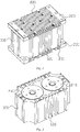
FIG. 1 is a schematic structural diagram of a large-capacity unit cell using electrode groups connected in parallel that is provided in an embodiment of the present invention; -
FIG. 2 is a partial schematic structural diagram of a large-capacity unit cell using electrode groups connected in parallel that is provided in an embodiment of the present invention; -
FIG. 3 is a front sectional view of a large-capacity unit cell using electrode groups connected in parallel that is provided in an embodiment of the present invention; and -
FIG. 4 is a front sectional view of a large-capacity unit cell using electrode groups connected in series that is provided in an embodiment of the present invention. - Reference signs: 100-Base body; 110-Accommodation cavity; 120-Third heat dissipation rib; 200-Electrode group module; 210-Electrode group; 220-Positive electrode cover; 221-First heat dissipation rib; 230-Negative electrode cover; 231-Second heat dissipation rib; 240-Positive electrode terminal cover; 250-Negative electrode terminal cover; 260-Positive electrode tab; 270-Negative electrode tab; and 280-Central shaft.
- The technical solutions in the present invention will be described clearly and completely below with reference to embodiments. Obviously, the described embodiments are some of, rather than all of, the embodiments of the present invention. Based on the embodiments of the present invention, all other embodiments obtained by those of ordinary skill in the art without involving any inventive effort fall within the scope of protection of the present invention.
- This embodiment provides a large-capacity unit cell, comprising a
base body 100 provided with a plurality ofaccommodation cavities 110, each of theaccommodation cavities 110 being provided with anelectrode group module 200, wherein theelectrode group modules 200 are connected in parallel; and theelectrode group module 200 comprises acentral shaft 280 and anelectrode group 210 wound around thecentral shaft 280, theelectrode group 210 comprises a positive electrode sheet, a negative electrode sheet and a separator, and the separator is used to separate the positive electrode sheet from the negative electrode sheet. - The large-capacity unit cell provided in this embodiment comprises a
base body 100 for accommodation and installation of all components, wherein thebase body 100 is provided with a plurality ofaccommodation cavities 110, each of theaccommodation cavities 110 is provided with anelectrode group module 200, and theelectrode group modules 200 are connected in parallel; and theelectrode group module 200 comprises anelectrode group 210, theelectrode group module 200 comprises theelectrode group 210 and acentral shaft 280 for theelectrode group 210 to be wound around, and theelectrode group 210 comprises a positive electrode sheet, a negative electrode sheet, and a separator used to separate the positive electrode sheet from the negative electrode sheet. - In a production process of the
electrode group 210 of the large-capacity unit cell, the positive electrode sheet, the negative electrode sheet, and the separator are wound around thecentral shaft 280, and after a winding radius meet the requirement, the electrode sheets and the separator do not need to be pulled from thecentral shaft 280, wherein as a constituent part of theelectrode group 210, thecentral shaft 280 is used for the production of the large-capacity unit cell. Because the wound electrode sheets and the separator do not need to be pulled from thecentral shaft 280, electrode sheets at layers and two sides of the separator can keep good uniformity, and the case where the separator inside theelectrode group 210 is damaged due to a pull can also be reduced. The above two points can both greatly reduce a potential security hazard that a short circuit occurs inside theelectrode group 210 of the large-capacity unit cell, so that the winding radius of theelectrode group 210 of the large-capacity cell is increased and the length of an electrode sheet is increased, thereby making the capacity of the large-capacity unit cell relatively large. - In addition, in the large-capacity unit cell, the
electrode group modules 200 may be connected in parallel, and may also be connected in other manners. When theelectrode group modules 200 are connected in parallel, a discharging current of the large-capacity unit cell is increased, so that the capacity of the cell is improved; when theelectrode group modules 200 are connected in series, the voltage of the large-capacity unit cell is increased, and for the same load, a discharging duration of the large-capacity unit cell is increased; in addition, theelectrode group modules 200 of the large-capacity unit cell may also be connected in a hybrid manner, so as to comprehensively use the above-mentioned two manners to improve the capacity and voltage of the cell. Regardless of whether theelectrode group modules 200 are connected in parallel, in series, or in a hybrid manner, compared with ordinary unit cells that are connected in parallel, in series, or in a hybrid manner, the large-capacity unit cell has a production process that is simplified, and can effectively avoid the occurrence of a short circuit when the ordinary unit cells are externally connected. - Specifically, in this embodiment, as shown in
FIGs. 3 and 4 , theaccommodation cavity 110 may pass through thebase body 100, and the positive electrode terminal and the negative electrode terminal of theelectrode group module 200 are respectively located at the two ends of theaccommodation cavity 110; and theelectrode group module 200 further comprises apositive electrode cover 220 and anegative electrode cover 230, thepositive electrode cover 220 covers a positive electrode terminal of theelectrode group 210, thenegative electrode cover 230 covers a negative electrode terminal of theelectrode group 210, and thepositive electrode cover 220 and thenegative electrode cover 230 are both fixedly connected to thebase body 100. The positive electrode terminal and the negative electrode terminal of theelectrode group module 200 are respectively located at the two ends of theaccommodation cavity 110, which effectively reduces the occurrence of a short circuit of the positive electrode terminal and the negative electrode terminal, and reduces the potential security hazard. The positive electrode terminal and the negative electrode terminal of the large-capacity unit cell are respectively located at the two opposite ends of thebase body 100, and heat generated inside the cell may be conducted away and dissipated from the two ends, thereby improving the heat dissipation performance of the large-capacity unit cell. In addition, thepositive electrode cover 220 and the positive electrode terminal of theelectrode group 210, and thenegative electrode cover 230 and the negative electrode terminal of theelectrode group 210 are both connected in a surface contact manner, so that the internal resistance of the large-capacity unit cell is relatively small, and thus the amount of heat generated inside the large-capacity unit cell is relatively small, and because the internal resistance is relatively small, the heat dissipation speed of the large-capacity unit cell is relatively fast, and the heat dissipation performance is further improved. - It should be noted that the
accommodation cavity 110 may also not pass through thebase body 100, and the positive electrode terminal and the negative electrode terminal of theelectrode group module 200 are located at the same end of theaccommodation cavity 110, that is, they are both located at an opening end of theaccommodation cavity 110. - Specifically, the
positive electrode cover 220 and thenegative electrode cover 230 may be both fixedly connected to thebase body 100 by means of a second threaded fastener. For connection through the second threaded fastener, thepositive electrode cover 220 and thenegative electrode cover 230 may be conveniently to detached and installed without damaging any one of thepositive electrode cover 220, thenegative electrode cover 230, and thebase body 100. - In this embodiment, as shown in
FIG. 3 , two,electrode group modules 200 may be provided, the twoelectrode group modules 200 may be connected in parallel, and are placed in the same direction in theaccommodation cavity 110; and the positive electrode covers 220 of the twoelectrode group modules 200 may be of an integral structure, and the negative electrode covers 230 of the twoelectrode group modules 200 may be of an integral structure. In the large-capacity unit cell, two positive electrode covers 220 are integrally connected, and two negative electrode covers 230 are integrally connected, so that the twoelectrode group modules 200 are connected in parallel, a discharging current is increased, and thus the cell capacity of the large-capacity unit cell is improved. - Specifically, a plurality of positive electrode covers 220 may be integrally formed, and a plurality of negative electrode covers 230 may be integrally formed, which not only simplifies the assembly process, but also improves the assembly precision, thereby improving the stability of connection between the
positive electrode cover 220 and thebase body 100, and between thenegative electrode cover 230 and thebase body 100, and thus improving the stability of the large-capacity unit cell. - In addition, when the
electrode group modules 200 of the large-capacity unit cell are connected in parallel, the positive electrode covers 220 or the negative electrode covers 230 may also be connected by connectors. Specifically, the connectors may comprise a first connector and a second connector. All of the positive electrode covers 220 may be connected by using the first connector, and all of the negative electrode covers 230 may be connected by using the second connector, so as to achieve the effect of connecting theelectrode group modules 200 in parallel. - In this embodiment, as shown in
FIG. 4 , twoelectrode group modules 200 may be provided, the twoelectrode group modules 200 may be connected in series, and are placed in opposite directions in theaccommodation cavity 110; and thepositive electrode cover 220 of one of theelectrode group modules 200 and thenegative electrode cover 230 of the otherelectrode group module 200 may be of an integral structure. In the large-capacity unit cell, thepositive electrode cover 220 of one of theelectrode group modules 200 is connected to thenegative electrode cover 230 of the otherelectrode group module 200, so that the twoelectrode group modules 200 are connected in series, and for the same load, the voltage of the large-capacity unit cell with the twoelectrode group modules 200 connected in series is increased, and the discharging duration is increased. - In addition, when the
electrode group modules 200 of the large-capacity unit cell are connected in series, the positive electrode covers 220 and the negative electrode covers 230 may also be connected by connectors. The connectors further comprise a third connector, wherein the third connector is used to connect thepositive electrode cover 220 of oneelectrode group module 200 to thenegative electrode cover 230 of the otherelectrode group module 200, so as to achieve the effect of connecting theelectrode group modules 200 in series. - It should be noted that, in this embodiment, there may also be three, four, five ...
electrode group modules 200 that are to be connected in parallel or in series, which can be connected in parallel or in series according to actual needs, and meanwhile, thebase body 100, theaccommodation cavities 110 of thebase body 100, thepositive electrode cover 220, thenegative electrode cover 230, etc. are also changed accordingly. - When three or more
electrode group modules 200 are provided, theelectrode group modules 200 may also be connected in a hybrid manner, that is, the cell capacity and the cell voltage are increased in the way of simultaneously increasing the current and the discharging duration. - In this embodiment, as shown in
FIGs. 2 to 4 , theelectrode group module 200 may further comprise a positiveelectrode terminal cover 240 and a negativeelectrode terminal cover 250, the positiveelectrode terminal cover 240 is arranged between thepositive electrode cover 220 and the positive electrode terminal of theelectrode group 210, and the negativeelectrode terminal cover 250 is arranged between thenegative electrode cover 230 and the negative electrode terminal of theelectrode group 210; the positiveelectrode terminal cover 240 is fixedly connected to thepositive electrode cover 220, and is connected to thecentral shaft 280 in an insulated manner; and the negativeelectrode terminal cover 250 is fixedly connected to thenegative electrode cover 230, and is connected to thecentral shaft 280 in an insulated manner. - Specifically, the positive
electrode terminal cover 240 may be connected to thepositive electrode cover 220 by means of a third threaded fastener, and the negativeelectrode terminal cover 250 may also be connected to thenegative electrode cover 230 by means of a third threaded fastener. - Specifically, in this embodiment, the positive
electrode terminal cover 240 and thepositive electrode cover 220 may be of an integral structure, and the negativeelectrode terminal cover 250 and thenegative electrode cover 230 may be of an integral structure, so that the structure of the large-capacity unit cell can be further simplified. - Specifically, as shown in
FIGs. 3 and 4 , a threaded hole is provided at each of two ends of thecentral shaft 280, the positiveelectrode terminal cover 240 may be connected to thecentral shaft 280 by means of a first threaded fastener, and an insulating part is arranged between the first threaded fastener and the positiveelectrode terminal cover 240; and the negativeelectrode terminal cover 250 may also be connected to thecentral shaft 280 by means of a first threaded fastener, and an insulating part is also arranged between the first threaded fastener and the negativeelectrode terminal cover 250. - The insulating part is used to avoid the occurrence of a short circuit inside the
electrode group 210 due to the first threaded fastener. Specifically, the insulating part may be sleeved on the first threaded fastener and located between the first threaded fastener and the positiveelectrode terminal cover 240 or between the first threaded fastener and the negativeelectrode terminal cover 250. - In this embodiment, the material of the
base body 100 may be engineering plastic. The engineering plastic has an insulation property, and thus can effectively avoid a short circuit between a positive electrode and a negative electrode. - In this embodiment, the
electrode group module 200 further comprises apositive electrode tab 260 and anegative electrode tab 270, thepositive electrode tab 260 is arranged between the positiveelectrode terminal cover 240 and the positive electrode terminal of theelectrode group 210, and thenegative electrode tab 270 is arranged between the negativeelectrode terminal cover 250 and the negative electrode terminal of theelectrode group 210; thepositive electrode tab 260 is fixedly connected to the positiveelectrode terminal cover 240, and is connected to thecentral shaft 280 in an insulated manner; and thenegative electrode tab 270 is fixedly connected to the negativeelectrode terminal cover 250, and is connected to thecentral shaft 280 in an insulated manner. Thepositive electrode tab 260 is connected to the positive electrode sheet and the positiveelectrode terminal cover 240, and thenegative electrode tab 270 is connected to the negative electrode sheet and the negativeelectrode terminal cover 250. The positiveelectrode terminal cover 240 is threadedly connected to thecentral shaft 280, which increases the connection firmness and can also enable thepositive electrode tab 260 to be in close contact with the positive electrode sheet, and thepositive electrode tab 260 to be in close contact with the positiveelectrode terminal cover 240, thereby reducing the internal resistance brought by a virtual connection and ensuring good electrical conductivity. Similarly, the negativeelectrode terminal cover 250 is threadedly connected to thecentral shaft 280, which increases the connection firmness and can also enable thenegative electrode tab 270 to be in close contact with the negative electrode sheet, and thenegative electrode tab 270 to be in close contact with the negativeelectrode terminal cover 250, thereby reducing the internal resistance brought by a virtual connection and ensuring good electrical conductivity. - In this embodiment, as shown in
FIG. 1 , a firstheat dissipation rib 221 may be arranged outside thepositive electrode cover 220, and a secondheat dissipation rib 231 may be arranged outside thenegative electrode cover 230. The firstheat dissipation rib 221 and the secondheat dissipation rib 231 increase the heat dissipation area of thepositive electrode cover 220 and thenegative electrode cover 230, thereby enhancing the heat dissipation performance of the large-capacity unit cell. - In this embodiment, the
base body 100 may be rectangular, theaccommodation cavity 110 may be a through hole, and an axial direction of the through hole is consistent with a height direction of thebase body 100. Due to a rectangular appearance, when the large-capacity unit cells are used to constitute a power battery or another energy storage battery, it is easy to arrange, and a plurality of large-capacity unit cells have good uniformity. - In this embodiment, a third
heat dissipation rib 120 may be arranged on an outer side wall of thebase body 100 to further enhance the heat dissipation performance of the large-capacity unit cell. - In addition, in this embodiment, the first threaded fastener, the second threaded fastener, and the third threaded fastener all increase the closeness between connectors, thereby reducing the internal resistance of the large-capacity unit cell, reducing the temperature inside the cell, and also allowing the heat inside the cell to be quickly conducted away.
- Specifically, the first threaded fastener, the second threaded fastener, and the third threaded fastener may each be a bolt.
- In this embodiment, the
base body 100 is provided with a safety valve, and the safety valve is used to discharge gas in theaccommodation cavity 110. Specifically, theaccommodation cavities 110 where theelectrode group modules 200 connected in parallel are located may be in communication, and the safety valve may be arranged in a communication passage, so that gas in twoadjacent accommodation cavities 110 can be discharged through a common safety valve. - In addition, the number of safety valves may also be consistent with the number of
electrode group modules 200 in each large-capacity unit cell, and safety valves are in one-to-one correspondence with positive electrode terminals ofelectrode group modules 200, or safety valves are in one-to-one correspondence with negative electrode terminals ofelectrode group modules 200; and the number of safety valves may also be twice the number ofelectrode group modules 200 in each large-capacity unit cell, and each of theelectrode group modules 200 corresponds to two safety valves, wherein one of the two safety valves corresponds to the positive electrode terminal of theelectrode group module 200, and the other of the two safety valves corresponds to the negative electrode terminal of theelectrode group module 200. - It should be noted that the specific location of the safety valve on the
base body 100 is not limited, provided that the functions of discharging gas inside the cell and reducing the potential security hazard can be implemented. - In addition, compared with a unit cell with a wound-type electrode group that has the same capacity as the large-capacity unit cell, the large-capacity unit cell uses
electrode group modules 200 connected in parallel, in series, or in a hybrid manner, and therefore the winding radius of asingle electrode group 210 is small and the heat dissipation performance is accordingly better; compared with a battery pack composed of unit cells that has the same capacity as the large-capacity unit cell, the large-capacity unit cell has a smaller volume and a greater energy density due to the use of an internal connection manner; and compared with a unit cell with a non-cylindricallywound electrode group 210, the large-capacity unit cell has a cylindricallywound electrode group 210, and theelectrode group 210 has a better compressive property in an axial direction. - Finally, it should be noted that the above embodiments are merely used for illustrating, rather than limiting, the technical solution of the present invention. Although the present invention has been described in detail with reference to the foregoing embodiments, it should be understood by those of ordinary skill in the art that the technical solutions specified in the foregoing embodiments could still be modified, or some or all of the technical features thereof may be equivalently replaced; and the modifications or replacements do not make the essence of the respective technical solutions deviate from the scope of the technical solutions of the embodiments of the present invention.
Claims (10)
- A large-capacity unit cell, characterized by comprising a base body (100) provided with a plurality of accommodation cavities (110), each of the accommodation cavities (110) being provided with an electrode group module (200), wherein the electrode group modules (200) are connected in parallel; and
the electrode group module (200) comprises a central shaft (280) and an electrode group (210) wound around the central shaft (280), the electrode group (210) comprises a positive electrode sheet, a negative electrode sheet and a separator, and the separator is used to separate the positive electrode sheet from the negative electrode sheet. - The large-capacity unit cell according to claim 1, characterized in that the accommodation cavity (110) passes through the base body (100), and a positive electrode terminal and a negative electrode terminal of the electrode group module (200) are respectively located at two ends of the accommodation cavity (110); and
the electrode group module (200) further comprises a positive electrode cover (220) and a negative electrode cover (230), the positive electrode cover (220) covers a positive electrode terminal of the electrode group (210), the negative electrode cover (230) covers a negative electrode terminal of the electrode group (210), and the positive electrode cover (220) and the negative electrode cover (230) are both fixedly connected to the base body (100). - The large-capacity unit cell according to claim 2, characterized in that two electrode group modules (200) are provided, the two electrode group modules (200) are connected in parallel, and are placed in the same direction in the accommodation cavity (110); and
the positive electrode covers (220) of the two electrode group modules (200) are of an integral structure, and the negative electrode covers (230) of the two electrode group modules (200) are of an integral structure. - The large-capacity unit cell according to claim 2 or 3, characterized in that the electrode group module (200) further comprises a positive electrode terminal cover (240) and a negative electrode terminal cover (250), the positive electrode terminal cover (240) is arranged between the positive electrode cover (220) and the positive electrode terminal of the electrode group (210), and the negative electrode terminal cover (250) is arranged between the negative electrode cover (230) and the negative electrode terminal of the electrode group (210);
the positive electrode terminal cover (240) is fixedly connected to the positive electrode cover (220), and is connected to the central shaft (280) in an insulated manner; and the negative electrode terminal cover (250) is fixedly connected to the negative electrode cover (230), and is connected to the central shaft (280) in an insulated manner. - The large-capacity unit cell according to claim 4, characterized in that two ends of the central shaft (280) are both provided with a threaded hole, the positive electrode terminal cover (240) is connected to the central shaft (280) by means of a first threaded fastener, and an insulating part is arranged between the first threaded fastener and the positive electrode terminal cover (240);
and/or the negative electrode terminal cover (250) is connected to the central shaft (280) by means of a first threaded fastener, and an insulating part is arranged between the first threaded fastener and the negative electrode terminal cover (250). - The large-capacity unit cell according to claim 5, characterized in that the electrode group module (200) further comprises a positive electrode tab (260) and a negative electrode tab (270), the positive electrode tab (260) is arranged between the positive electrode terminal cover (240) and the positive electrode terminal of the electrode group (210), and the negative electrode tab (270) is arranged between the negative electrode terminal cover (250) and the negative electrode terminal of the electrode group (210);
the positive electrode tab (260) is fixedly connected to the positive electrode terminal cover (240), and is connected to the central shaft (280) in an insulated manner; and the negative electrode tab (270) is fixedly connected to the negative electrode terminal cover (250), and is connected to the central shaft (280) in an insulated manner. - The large-capacity unit cell according to claim 2, characterized in that a first heat dissipation rib (221) is arranged outside the positive electrode cover (220), and a second heat dissipation rib (231) is arranged outside the negative electrode cover (230).
- The large-capacity unit cell according to any one of claims 1 to 3, characterized in that the base body (100) is rectangular, the accommodation cavity (110) is a through hole, and an axial direction of the through hole is consistent with a height direction of the base body (100).
- The large-capacity unit cell according to any one of claims 1 to 3, characterized in that a third heat dissipation rib (120) is arranged on an outer side wall of the base body (100).
- The large-capacity unit cell according to any one of claims 1 to 3, characterized in that the base body (100) is provided with a safety valve, and the safety valve is used to discharge gas in the accommodation cavity (110).
Applications Claiming Priority (1)
| Application Number | Priority Date | Filing Date | Title |
|---|---|---|---|
| CN201920990031.4U CN209843858U (en) | 2019-06-27 | 2019-06-27 | Large-capacity single battery |
Publications (2)
| Publication Number | Publication Date |
|---|---|
| EP3758086A1 true EP3758086A1 (en) | 2020-12-30 |
| EP3758086B1 EP3758086B1 (en) | 2025-07-02 |
Family
ID=68461698
Family Applications (1)
| Application Number | Title | Priority Date | Filing Date |
|---|---|---|---|
| EP19200881.1A Active EP3758086B1 (en) | 2019-06-27 | 2019-10-01 | Large-capacity unit cell |
Country Status (2)
| Country | Link |
|---|---|
| EP (1) | EP3758086B1 (en) |
| CN (1) | CN209843858U (en) |
Cited By (1)
| Publication number | Priority date | Publication date | Assignee | Title |
|---|---|---|---|---|
| CN116114117A (en) * | 2021-02-09 | 2023-05-12 | 宁德时代新能源科技股份有限公司 | Electrode assembly and battery cell, battery, device, manufacturing method and manufacturing device |
Families Citing this family (4)
| Publication number | Priority date | Publication date | Assignee | Title |
|---|---|---|---|---|
| CN116014362B (en) * | 2021-10-21 | 2025-03-07 | 宁德时代新能源科技股份有限公司 | Electrode assembly and related preparation device, battery cell and battery |
| CN114566771A (en) * | 2022-03-09 | 2022-05-31 | 陕西奥林波斯电力能源有限责任公司 | High-capacity battery |
| CN115224446A (en) * | 2022-06-30 | 2022-10-21 | 陕西奥林波斯电力能源有限责任公司 | Battery conductive device with phase-change material and high-capacity battery pack |
| WO2023169395A1 (en) * | 2022-03-09 | 2023-09-14 | 陕西奥林波斯电力能源有限责任公司 | High-capacity battery pack |
Citations (6)
| Publication number | Priority date | Publication date | Assignee | Title |
|---|---|---|---|---|
| KR20090008071A (en) * | 2007-07-16 | 2009-01-21 | 주식회사 엘지화학 | Secondary battery including multiple electrode assemblies in one battery case |
| CN101728493A (en) * | 2009-08-28 | 2010-06-09 | 深圳市慧通天下科技股份有限公司 | Battery shell and battery comprising same |
| EP2296205A1 (en) * | 2009-09-10 | 2011-03-16 | Samsung SDI Co., Ltd. | Rechargeable battery |
| EP2378590A1 (en) * | 2010-04-12 | 2011-10-19 | Samsung SDI Co., Ltd. | Secondary battery |
| EP2557609A1 (en) * | 2011-08-08 | 2013-02-13 | Samsung SDI Co., Ltd. | Rechargeable battery and method for fabricating the same |
| US20160301118A1 (en) * | 2013-04-09 | 2016-10-13 | Commissariat A L'energie Atomique Et Aux Energies Alternatives | Lithium electrochemical storage battery having a casing providing improved thermal dissipation, associated battery pack and production processes |
-
2019
- 2019-06-27 CN CN201920990031.4U patent/CN209843858U/en active Active
- 2019-10-01 EP EP19200881.1A patent/EP3758086B1/en active Active
Patent Citations (6)
| Publication number | Priority date | Publication date | Assignee | Title |
|---|---|---|---|---|
| KR20090008071A (en) * | 2007-07-16 | 2009-01-21 | 주식회사 엘지화학 | Secondary battery including multiple electrode assemblies in one battery case |
| CN101728493A (en) * | 2009-08-28 | 2010-06-09 | 深圳市慧通天下科技股份有限公司 | Battery shell and battery comprising same |
| EP2296205A1 (en) * | 2009-09-10 | 2011-03-16 | Samsung SDI Co., Ltd. | Rechargeable battery |
| EP2378590A1 (en) * | 2010-04-12 | 2011-10-19 | Samsung SDI Co., Ltd. | Secondary battery |
| EP2557609A1 (en) * | 2011-08-08 | 2013-02-13 | Samsung SDI Co., Ltd. | Rechargeable battery and method for fabricating the same |
| US20160301118A1 (en) * | 2013-04-09 | 2016-10-13 | Commissariat A L'energie Atomique Et Aux Energies Alternatives | Lithium electrochemical storage battery having a casing providing improved thermal dissipation, associated battery pack and production processes |
Cited By (1)
| Publication number | Priority date | Publication date | Assignee | Title |
|---|---|---|---|---|
| CN116114117A (en) * | 2021-02-09 | 2023-05-12 | 宁德时代新能源科技股份有限公司 | Electrode assembly and battery cell, battery, device, manufacturing method and manufacturing device |
Also Published As
| Publication number | Publication date |
|---|---|
| CN209843858U (en) | 2019-12-24 |
| EP3758086B1 (en) | 2025-07-02 |
Similar Documents
| Publication | Publication Date | Title |
|---|---|---|
| EP3758086B1 (en) | Large-capacity unit cell | |
| JP7673125B2 (en) | Battery module and power battery pack | |
| WO2023035990A1 (en) | Single battery, battery module, and battery pack | |
| CN110265616B (en) | Single battery, power battery pack and vehicle | |
| CN112909398A (en) | Battery, electric equipment, method and equipment for preparing battery | |
| WO2020252803A1 (en) | Single cell battery, power battery pack and vehicle | |
| CN201904409U (en) | Restorable large lithium-ion secondary battery | |
| CN219303812U (en) | Battery cells, batteries and electrical devices | |
| US20250391950A1 (en) | Battery and electrical apparatus | |
| US20260011891A1 (en) | Battery and electrical apparatus | |
| US20250070142A1 (en) | Battery electrode plate, electrode plate assembly, battery and electrical device | |
| US20220352596A1 (en) | Battery cell, battery, electrical device and method for preparing battery cell | |
| CN107230801A (en) | A kind of secure mass lithium ion battery | |
| WO2023221606A1 (en) | Current collector, electrode sheet, electrode assembly, battery cell, battery and electric apparatus | |
| WO2023159487A1 (en) | Battery, electrical device, and method and device for preparing battery | |
| KR102832073B1 (en) | Batteries, electrical devices, battery manufacturing methods and devices | |
| CN222126920U (en) | Batteries, battery modules, battery packs, energy storage devices and power consumption devices | |
| CN220341278U (en) | Battery and electric equipment | |
| CN218005081U (en) | Battery pack | |
| WO2023155212A1 (en) | Battery, electric device, and battery preparation method and device | |
| CN206976496U (en) | A kind of secure mass lithium ion battery | |
| CN218867190U (en) | Battery cell, battery pack and vehicle | |
| CN220155621U (en) | Batteries and electrical equipment | |
| CN218648005U (en) | Lithium ion battery | |
| CN221041219U (en) | Electrode assembly, battery cell, battery and electricity utilization device |
Legal Events
| Date | Code | Title | Description |
|---|---|---|---|
| PUAI | Public reference made under article 153(3) epc to a published international application that has entered the european phase |
Free format text: ORIGINAL CODE: 0009012 |
|
| STAA | Information on the status of an ep patent application or granted ep patent |
Free format text: STATUS: THE APPLICATION HAS BEEN PUBLISHED |
|
| AK | Designated contracting states |
Kind code of ref document: A1 Designated state(s): AL AT BE BG CH CY CZ DE DK EE ES FI FR GB GR HR HU IE IS IT LI LT LU LV MC MK MT NL NO PL PT RO RS SE SI SK SM TR |
|
| AX | Request for extension of the european patent |
Extension state: BA ME |
|
| STAA | Information on the status of an ep patent application or granted ep patent |
Free format text: STATUS: REQUEST FOR EXAMINATION WAS MADE |
|
| 17P | Request for examination filed |
Effective date: 20210628 |
|
| RBV | Designated contracting states (corrected) |
Designated state(s): AL AT BE BG CH CY CZ DE DK EE ES FI FR GB GR HR HU IE IS IT LI LT LU LV MC MK MT NL NO PL PT RO RS SE SI SK SM TR |
|
| STAA | Information on the status of an ep patent application or granted ep patent |
Free format text: STATUS: EXAMINATION IS IN PROGRESS |
|
| 17Q | First examination report despatched |
Effective date: 20240112 |
|
| REG | Reference to a national code |
Ref country code: DE Ref legal event code: R079 Free format text: PREVIOUS MAIN CLASS: H01M0002100000 Ipc: H01M0010040000 Ref document number: 602019071867 Country of ref document: DE |
|
| GRAP | Despatch of communication of intention to grant a patent |
Free format text: ORIGINAL CODE: EPIDOSNIGR1 |
|
| STAA | Information on the status of an ep patent application or granted ep patent |
Free format text: STATUS: GRANT OF PATENT IS INTENDED |
|
| INTG | Intention to grant announced |
Effective date: 20250331 |
|
| RIC1 | Information provided on ipc code assigned before grant |
Ipc: H01M 50/528 20210101ALI20250321BHEP Ipc: H01M 50/30 20210101ALI20250321BHEP Ipc: H01M 50/271 20210101ALI20250321BHEP Ipc: H01M 50/262 20210101ALI20250321BHEP Ipc: H01M 50/227 20210101ALI20250321BHEP Ipc: H01M 50/213 20210101ALI20250321BHEP Ipc: H01M 10/6551 20140101ALI20250321BHEP Ipc: H01M 10/04 20060101AFI20250321BHEP |
|
| GRAS | Grant fee paid |
Free format text: ORIGINAL CODE: EPIDOSNIGR3 |
|
| GRAA | (expected) grant |
Free format text: ORIGINAL CODE: 0009210 |
|
| STAA | Information on the status of an ep patent application or granted ep patent |
Free format text: STATUS: THE PATENT HAS BEEN GRANTED |
|
| AK | Designated contracting states |
Kind code of ref document: B1 Designated state(s): AL AT BE BG CH CY CZ DE DK EE ES FI FR GB GR HR HU IE IS IT LI LT LU LV MC MK MT NL NO PL PT RO RS SE SI SK SM TR |
|
| REG | Reference to a national code |
Ref country code: GB Ref legal event code: FG4D |
|
| REG | Reference to a national code |
Ref country code: CH Ref legal event code: EP |
|
| REG | Reference to a national code |
Ref country code: DE Ref legal event code: R096 Ref document number: 602019071867 Country of ref document: DE |
|
| REG | Reference to a national code |
Ref country code: IE Ref legal event code: FG4D |
|
| REG | Reference to a national code |
Ref country code: NL Ref legal event code: MP Effective date: 20250702 |
|
| PG25 | Lapsed in a contracting state [announced via postgrant information from national office to epo] |
Ref country code: PT Free format text: LAPSE BECAUSE OF FAILURE TO SUBMIT A TRANSLATION OF THE DESCRIPTION OR TO PAY THE FEE WITHIN THE PRESCRIBED TIME-LIMIT Effective date: 20251103 |
|
| PG25 | Lapsed in a contracting state [announced via postgrant information from national office to epo] |
Ref country code: NL Free format text: LAPSE BECAUSE OF FAILURE TO SUBMIT A TRANSLATION OF THE DESCRIPTION OR TO PAY THE FEE WITHIN THE PRESCRIBED TIME-LIMIT Effective date: 20250702 |
|
| REG | Reference to a national code |
Ref country code: AT Ref legal event code: MK05 Ref document number: 1810309 Country of ref document: AT Kind code of ref document: T Effective date: 20250702 |
|
| PG25 | Lapsed in a contracting state [announced via postgrant information from national office to epo] |
Ref country code: IS Free format text: LAPSE BECAUSE OF FAILURE TO SUBMIT A TRANSLATION OF THE DESCRIPTION OR TO PAY THE FEE WITHIN THE PRESCRIBED TIME-LIMIT Effective date: 20251102 |
|
| PG25 | Lapsed in a contracting state [announced via postgrant information from national office to epo] |
Ref country code: NO Free format text: LAPSE BECAUSE OF FAILURE TO SUBMIT A TRANSLATION OF THE DESCRIPTION OR TO PAY THE FEE WITHIN THE PRESCRIBED TIME-LIMIT Effective date: 20251002 |
|
| REG | Reference to a national code |
Ref country code: LT Ref legal event code: MG9D |
|
| PG25 | Lapsed in a contracting state [announced via postgrant information from national office to epo] |
Ref country code: AT Free format text: LAPSE BECAUSE OF FAILURE TO SUBMIT A TRANSLATION OF THE DESCRIPTION OR TO PAY THE FEE WITHIN THE PRESCRIBED TIME-LIMIT Effective date: 20250702 |
|
| PG25 | Lapsed in a contracting state [announced via postgrant information from national office to epo] |
Ref country code: FI Free format text: LAPSE BECAUSE OF FAILURE TO SUBMIT A TRANSLATION OF THE DESCRIPTION OR TO PAY THE FEE WITHIN THE PRESCRIBED TIME-LIMIT Effective date: 20250702 |
|
| PG25 | Lapsed in a contracting state [announced via postgrant information from national office to epo] |
Ref country code: HR Free format text: LAPSE BECAUSE OF FAILURE TO SUBMIT A TRANSLATION OF THE DESCRIPTION OR TO PAY THE FEE WITHIN THE PRESCRIBED TIME-LIMIT Effective date: 20250702 |
|
| PG25 | Lapsed in a contracting state [announced via postgrant information from national office to epo] |
Ref country code: GR Free format text: LAPSE BECAUSE OF FAILURE TO SUBMIT A TRANSLATION OF THE DESCRIPTION OR TO PAY THE FEE WITHIN THE PRESCRIBED TIME-LIMIT Effective date: 20251003 |
|
| PG25 | Lapsed in a contracting state [announced via postgrant information from national office to epo] |
Ref country code: SE Free format text: LAPSE BECAUSE OF FAILURE TO SUBMIT A TRANSLATION OF THE DESCRIPTION OR TO PAY THE FEE WITHIN THE PRESCRIBED TIME-LIMIT Effective date: 20250702 Ref country code: CZ Free format text: LAPSE BECAUSE OF FAILURE TO SUBMIT A TRANSLATION OF THE DESCRIPTION OR TO PAY THE FEE WITHIN THE PRESCRIBED TIME-LIMIT Effective date: 20250702 |
|
| PG25 | Lapsed in a contracting state [announced via postgrant information from national office to epo] |
Ref country code: LV Free format text: LAPSE BECAUSE OF FAILURE TO SUBMIT A TRANSLATION OF THE DESCRIPTION OR TO PAY THE FEE WITHIN THE PRESCRIBED TIME-LIMIT Effective date: 20250702 |
|
| PG25 | Lapsed in a contracting state [announced via postgrant information from national office to epo] |
Ref country code: PL Free format text: LAPSE BECAUSE OF FAILURE TO SUBMIT A TRANSLATION OF THE DESCRIPTION OR TO PAY THE FEE WITHIN THE PRESCRIBED TIME-LIMIT Effective date: 20250702 Ref country code: BG Free format text: LAPSE BECAUSE OF FAILURE TO SUBMIT A TRANSLATION OF THE DESCRIPTION OR TO PAY THE FEE WITHIN THE PRESCRIBED TIME-LIMIT Effective date: 20250702 |
|
| PG25 | Lapsed in a contracting state [announced via postgrant information from national office to epo] |
Ref country code: RS Free format text: LAPSE BECAUSE OF FAILURE TO SUBMIT A TRANSLATION OF THE DESCRIPTION OR TO PAY THE FEE WITHIN THE PRESCRIBED TIME-LIMIT Effective date: 20251002 |
|
| PG25 | Lapsed in a contracting state [announced via postgrant information from national office to epo] |
Ref country code: ES Free format text: LAPSE BECAUSE OF FAILURE TO SUBMIT A TRANSLATION OF THE DESCRIPTION OR TO PAY THE FEE WITHIN THE PRESCRIBED TIME-LIMIT Effective date: 20250702 |
|
| PG25 | Lapsed in a contracting state [announced via postgrant information from national office to epo] |
Ref country code: RO Free format text: LAPSE BECAUSE OF FAILURE TO SUBMIT A TRANSLATION OF THE DESCRIPTION OR TO PAY THE FEE WITHIN THE PRESCRIBED TIME-LIMIT Effective date: 20250702 |
|
| PG25 | Lapsed in a contracting state [announced via postgrant information from national office to epo] |
Ref country code: SM Free format text: LAPSE BECAUSE OF FAILURE TO SUBMIT A TRANSLATION OF THE DESCRIPTION OR TO PAY THE FEE WITHIN THE PRESCRIBED TIME-LIMIT Effective date: 20250702 |
|
| PG25 | Lapsed in a contracting state [announced via postgrant information from national office to epo] |
Ref country code: DK Free format text: LAPSE BECAUSE OF FAILURE TO SUBMIT A TRANSLATION OF THE DESCRIPTION OR TO PAY THE FEE WITHIN THE PRESCRIBED TIME-LIMIT Effective date: 20250702 |
|
| PG25 | Lapsed in a contracting state [announced via postgrant information from national office to epo] |
Ref country code: IT Free format text: LAPSE BECAUSE OF FAILURE TO SUBMIT A TRANSLATION OF THE DESCRIPTION OR TO PAY THE FEE WITHIN THE PRESCRIBED TIME-LIMIT Effective date: 20250702 |
|
| PG25 | Lapsed in a contracting state [announced via postgrant information from national office to epo] |
Ref country code: SK Free format text: LAPSE BECAUSE OF FAILURE TO SUBMIT A TRANSLATION OF THE DESCRIPTION OR TO PAY THE FEE WITHIN THE PRESCRIBED TIME-LIMIT Effective date: 20250702 Ref country code: EE Free format text: LAPSE BECAUSE OF FAILURE TO SUBMIT A TRANSLATION OF THE DESCRIPTION OR TO PAY THE FEE WITHIN THE PRESCRIBED TIME-LIMIT Effective date: 20250702 |