EP3758085B1 - Battery pack - Google Patents
Battery pack Download PDFInfo
- Publication number
- EP3758085B1 EP3758085B1 EP18912740.0A EP18912740A EP3758085B1 EP 3758085 B1 EP3758085 B1 EP 3758085B1 EP 18912740 A EP18912740 A EP 18912740A EP 3758085 B1 EP3758085 B1 EP 3758085B1
- Authority
- EP
- European Patent Office
- Prior art keywords
- insulating
- bottom plate
- battery pack
- strips
- buffer sheet
- Prior art date
- Legal status (The legal status is an assumption and is not a legal conclusion. Google has not performed a legal analysis and makes no representation as to the accuracy of the status listed.)
- Active
Links
Images


Classifications
-
- H—ELECTRICITY
- H01—ELECTRIC ELEMENTS
- H01M—PROCESSES OR MEANS, e.g. BATTERIES, FOR THE DIRECT CONVERSION OF CHEMICAL ENERGY INTO ELECTRICAL ENERGY
- H01M50/00—Constructional details or processes of manufacture of the non-active parts of electrochemical cells other than fuel cells, e.g. hybrid cells
- H01M50/50—Current conducting connections for cells or batteries
- H01M50/528—Fixed electrical connections, i.e. not intended for disconnection
-
- H—ELECTRICITY
- H01—ELECTRIC ELEMENTS
- H01M—PROCESSES OR MEANS, e.g. BATTERIES, FOR THE DIRECT CONVERSION OF CHEMICAL ENERGY INTO ELECTRICAL ENERGY
- H01M50/00—Constructional details or processes of manufacture of the non-active parts of electrochemical cells other than fuel cells, e.g. hybrid cells
- H01M50/20—Mountings; Secondary casings or frames; Racks, modules or packs; Suspension devices; Shock absorbers; Transport or carrying devices; Holders
- H01M50/204—Racks, modules or packs for multiple batteries or multiple cells
- H01M50/207—Racks, modules or packs for multiple batteries or multiple cells characterised by their shape
- H01M50/209—Racks, modules or packs for multiple batteries or multiple cells characterised by their shape adapted for prismatic or rectangular cells
-
- H—ELECTRICITY
- H01—ELECTRIC ELEMENTS
- H01M—PROCESSES OR MEANS, e.g. BATTERIES, FOR THE DIRECT CONVERSION OF CHEMICAL ENERGY INTO ELECTRICAL ENERGY
- H01M50/00—Constructional details or processes of manufacture of the non-active parts of electrochemical cells other than fuel cells, e.g. hybrid cells
- H01M50/20—Mountings; Secondary casings or frames; Racks, modules or packs; Suspension devices; Shock absorbers; Transport or carrying devices; Holders
- H01M50/289—Mountings; Secondary casings or frames; Racks, modules or packs; Suspension devices; Shock absorbers; Transport or carrying devices; Holders characterised by spacing elements or positioning means within frames, racks or packs
-
- H—ELECTRICITY
- H01—ELECTRIC ELEMENTS
- H01M—PROCESSES OR MEANS, e.g. BATTERIES, FOR THE DIRECT CONVERSION OF CHEMICAL ENERGY INTO ELECTRICAL ENERGY
- H01M50/00—Constructional details or processes of manufacture of the non-active parts of electrochemical cells other than fuel cells, e.g. hybrid cells
- H01M50/50—Current conducting connections for cells or batteries
- H01M50/572—Means for preventing undesired use or discharge
- H01M50/584—Means for preventing undesired use or discharge for preventing incorrect connections inside or outside the batteries
- H01M50/59—Means for preventing undesired use or discharge for preventing incorrect connections inside or outside the batteries characterised by the protection means
- H01M50/593—Spacers; Insulating plates
-
- Y—GENERAL TAGGING OF NEW TECHNOLOGICAL DEVELOPMENTS; GENERAL TAGGING OF CROSS-SECTIONAL TECHNOLOGIES SPANNING OVER SEVERAL SECTIONS OF THE IPC; TECHNICAL SUBJECTS COVERED BY FORMER USPC CROSS-REFERENCE ART COLLECTIONS [XRACs] AND DIGESTS
- Y02—TECHNOLOGIES OR APPLICATIONS FOR MITIGATION OR ADAPTATION AGAINST CLIMATE CHANGE
- Y02E—REDUCTION OF GREENHOUSE GAS [GHG] EMISSIONS, RELATED TO ENERGY GENERATION, TRANSMISSION OR DISTRIBUTION
- Y02E60/00—Enabling technologies; Technologies with a potential or indirect contribution to GHG emissions mitigation
- Y02E60/10—Energy storage using batteries
Definitions
- the present application relates to the technical field of batteries, in particular to a battery pack case and a battery pack.
- secondary batteries rechargeable batteries
- a bus bar is needed to connect each unit cell in series or in parallel.
- a plurality of unit cells form a battery module in groups.
- a plurality of battery modules are packaged through a pack case to form a battery pack.
- the technical solutions basically adopt the bottom plate-free solution with the bottom of the battery module glued.
- the document CN206349427U discloses an electricity core limit structure and electronic box, wherein the core limit structure comprises a plurality of spacer striper having a body and a limit portion.
- the document EP2332761A1 discloses a battery case, wherein battery case comprises a battery tray and a battery cover which covers the battery tray.
- the battery tray is formed from a resin and has a bottom wall on which batteries are mounted and a peripheral side wall which surrounds the periphery of the bottom wall.
- the document CN107507938A discloses a battery module fixation structure, wherein the battery module fixation structure comprises a battery box body, multiple battery modules accommodated in the battery box body and at least one fixing strip for fixedly mounting the multiple battery modules in the battery box body.
- Embodiments of the present application provide a battery pack case and a battery pack.
- the battery pack case can effectively maintain the insulation state between the battery pack case and the unit cell and avoid the abnormal insulation alarm caused by contacting between the unit cell and the battery pack case.
- the amount of glue can be controlled to ensure the uniform thickness of the glue.
- Fig. 1 schematically shows an exploded structure of a battery pack case 1 and a unit cell 99 according to an embodiment of the present application.
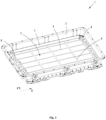
- Fig. 2 schematically shows the overall structure of the battery pack case 1 according to an embodiment of the present application.
- Fig. 3 schematically shows the combined structure of the first insulating strip 4, the first side insulating strip 7 and the second side insulating strip 8 according to an embodiment of the present application.
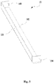
- Fig. 4 schematically shows the overall structure of the first insulating buffer sheet 9 according to an embodiment of the present application.
- Fig. 5 schematically shows the overall structure of the second insulating buffer sheet 10 according to an embodiment of the present application. As shown in Fig.
- the battery pack case 1 of the present application is used to accommodate a unit cell 99 to form protection for the unit cell 99. At the same time, it can also accommodate the wiring harness or other electronic components related to the use of the unit cell 99 and protect them.
- the unit cell 99 of the present embodiment may be a square battery.
- the first side insulating strip 7 includes a first long side 7a and a second long side 7b.
- the first long side 7a is connected to the side plate 3, and the second long side 7b is connected to the bottom plate 2.
- the first long side 7a and the second long side 7b are perpendicular to each other, so that the entire cross section of the first side insulating strip 7 includes an L-shaped structure.
- An embodiment of the present application further proposes a battery pack, which includes a battery pack case 1 and a plurality of battery assemblies provided in the battery pack case 1.
- the battery pack can provide power for the electrical equipment.
- a plurality of battery assemblies are arranged side by side along the width direction Y of the bottom plate 2.
- Each battery assembly includes a plurality of unit cells 99 arranged side by side along the length direction X of the bottom plate 2.
- the first insulating strip 4 is provided between the bottom of the battery assembly and the bottom plate 2. Since the first insulating strip 4 insulates and isolates the unit cell 99 from the bottom plate 2, the unit cell 99 will not contact with the bottom plate 2, so that the overall safety of the battery pack is good and the working process is stable.
Landscapes
- Chemical & Material Sciences (AREA)
- Chemical Kinetics & Catalysis (AREA)
- Electrochemistry (AREA)
- General Chemical & Material Sciences (AREA)
- Battery Mounting, Suspending (AREA)
- Connection Of Batteries Or Terminals (AREA)
Description
- The present application relates to the technical field of batteries, in particular to a battery pack case and a battery pack.
- With the continuous development of new energy technologies, secondary batteries (rechargeable batteries) are more and more widely used, for example, hybrid vehicles or electric vehicles. However, the safety issues of devices using secondary batteries are gradually exposed to the public's vision, which also affects the development of secondary batteries. When the unit cells usually need to be used in groups, a bus bar is needed to connect each unit cell in series or in parallel. A plurality of unit cells form a battery module in groups. A plurality of battery modules are packaged through a pack case to form a battery pack. At present, in order to improve the energy density of the battery pack, the technical solutions basically adopt the bottom plate-free solution with the bottom of the battery module glued. However, the use of the bottom plate-free solution will also bring about the problem of insulation of the battery pack and the control of the amount of glue applied to the bottom of the battery, which cannot guarantee the safe distance and gluing thickness between the unit cell and the pack case. The battery system often causes an abnormal insulation alarm due to direct contact between the pack case and the unit cell, and the battery pack may also cause occurrence of dangerous situation due to the abnormal insulation.
- The document
CN206349427U discloses an electricity core limit structure and electronic box, wherein the core limit structure comprises a plurality of spacer striper having a body and a limit portion. - The document
EP2332761A1 discloses a battery case, wherein battery case comprises a battery tray and a battery cover which covers the battery tray. The battery tray is formed from a resin and has a bottom wall on which batteries are mounted and a peripheral side wall which surrounds the periphery of the bottom wall. - The document
CN107507938A discloses a battery module fixation structure, wherein the battery module fixation structure comprises a battery box body, multiple battery modules accommodated in the battery box body and at least one fixing strip for fixedly mounting the multiple battery modules in the battery box body. - Embodiments of the present application provide a battery pack case and a battery pack. The battery pack case can effectively maintain the insulation state between the battery pack case and the unit cell and avoid the abnormal insulation alarm caused by contacting between the unit cell and the battery pack case. At the same time, the amount of glue can be controlled to ensure the uniform thickness of the glue.
- In an aspect, an embodiment of the present application proposes a battery pack including a plurality of unit cells and a battery pack case, which includes: a bottom plate and a side plate connected to the bottom plate, the bottom plate and the side plate surround to define an accommodating portion for accommodating the plurality of unit cells; a plurality of first insulating strips arranged on a surface of the bottom plate facing the accommodating portion, and a plurality of first insulating strips are sequentially spaced along the length direction or the width direction of the bottom plate, and a glue receiving groove in which an insulating glue is filed is formed between two adjacent first insulating strips. The plurality of first insulating strips are configure to block the insulating glue from overflowing by a thickness of the plurality of first insulating strips. The plurality of unit cells are fixed to the plurality of first insulating strips on the bottom plate by the insulating glue filled in the glue receiving groove. The plurality of first insulating strips are all plastic or insulating resin, and the bottom plate and the side plate are steel structures.
- According to an aspect of an embodiment of the present application, the battery pack case further includes a plurality of second insulating strips, a plurality of first insulating strips and each of the second insulating strips are arranged to intersect, a glue receiving groove is formed between two adjacent first insulating strips and two adjacent second insulating strips. The plurality of second insulating strips are all plastic or insulating resin.
- According to an aspect of an embodiment of the present application, the battery pack case further includes a first side insulating strip that extends along the length direction of the bottom plate and is disposed at connection between the long side of the bottom plate along the length direction of the bottom plate and the side plate in covering manner. The first side insulating strip is plastic or insulating resin.
- According to an aspect of the embodiment of the present application, a cross section of the first side insulating strip is L-shaped.
- According to an aspect of an embodiment of the present application, the battery pack case further includes a second side insulating strip, the second side insulating strip extends along the width direction of the bottom plate, and is disposed at a wide side of the bottom plate along the width direction of the bottom plate, connected to the side plate in covering manner. The second side insulating strip is plastic or insulating resin. The battery pack case of the embodiment of the present application includes a bottom plate capable of supporting a unit cell and a side plate connected to the bottom plate. A plurality of first insulating strips with good insulation performance are provided on the bottom plate. The first insulating strips are arranged between the bottom of the unit cell and the bottom plate, which can isolate the unit cell from the bottom plate, keep a predetermined distance between them and insulate from each other, and avoid contacting between them and the occurrence of insulation abnormalities, causing electrical connection between the two and there is a danger of short circuit and fire. A glue receiving groove is formed between two adjacent first insulating strips to facilitate filling a predetermined amount of insulation glue. The first insulating strip can prevent the insulating glue from overflowing. The first insulating strip can control the thickness of the insulating glue layer through its own thickness, thereby ensuring a flat surface of the insulating glue and also avoiding waste of the insulating glue.
- In another aspect, an embodiment of the present application provides a battery pack, including: a battery pack case including a bottom plate and a side plate connected to the bottom plate, the bottom plate and the side plate surround to define an accommodating portion; and a plurality of first insulating strips provided on a surface of the bottom plate facing the accommodating portion, the plurality of first insulating strips are sequentially spaced along a length direction or a width direction of the bottom plate, and a glue receiving groove in which an insulating glue is filed is formed between two adjacent first insulating strips; and a plurality of battery assemblies, provided in the accommodating portion, the plurality of battery assemblies are arranged side by side along the width direction of the bottom plate, each battery assembly includes a plurality of unit cells arranged side by side along the length direction of the bottom plate; the first insulating strip is disposed between the bottom of the battery assembly and the bottom plate. The plurality of first insulating strips are configured to block the insulating glue from overflowing by a thickness of the plurality of first insulating strips. The plurality of unit cells are fixed to the plurality of first insulating strips on the bottom plate by the insulating glue filled in the glue receiving groove. The plurality of first insulating strips are all plastic or insulating resin, and the bottom plate and the side plate are steel structures.
- According to another aspect of the embodiments of the present application, the battery pack further includes a first insulating buffer sheet that extends along the length direction of the bottom plate, and the first insulating buffer sheet is disposed between the battery assembly adjacent to the side plate and the battery pack case. The first insulating buffer sheet is plastic or rubber.
- According to another aspect of the embodiments of the present application, the first insulating buffer sheet includes a first connection section and a second connection section that intersect, the first connection section is bonded to a surface of the battery assembly facing the side plate, and the second connection section is positioned between the bottom of the battery assembly and the bottom plate.
- According to another aspect of the embodiments of the present application, the battery pack further includes a second insulating buffer sheet, the second insulating buffer sheet extends along the width direction of the bottom plate, a second insulating buffer sheet is provided between the bottoms of the two unit cells positioned on the outermost side of the battery assembly and the battery pack case. The second insulating buffer sheet is plastic or rubber.
- According to another aspect of the embodiments of the present application, the second insulating buffer sheet includes a accommodating recess, a part of the bottoms of the two unit cells is inserted into the accommodating recess to be covered by the second insulating buffer sheet, and the second insulating buffer sheet is bonded to the two unit cells.
- The features, advantages, and technical effects of exemplary embodiments of the present application will be described below with reference to the drawings.
-
Fig. 1 is a schematic diagram of an exploded structure of a battery pack case and a unit cell according to an embodiment of the present application; -
Fig.2 is a schematic diagram of the overall structure of a battery pack case according to an embodiment of the present application; -
Fig. 3 is a schematic diagram of a combined structure of a first insulating strip, a first side insulating strip, and a second side insulating strip according to an embodiment of the present application; -
Fig. 4 is a schematic diagram of the overall structure of a first insulating buffer sheet according to an embodiment of the present application; -
Fig. 5 is a schematic diagram of the overall structure of a second insulating buffer sheet according to an embodiment of the present application. - In the drawings, the drawings are not drawn to actual scale.
- 1. battery pack case;
- 2. bottom plate;
- 3. side plate;
- 4. first insulating strip;
- 5. glue receiving groove;
- 6. second insulating strip;
- 7. first side insulating strip; 7a. first long side; 7b. second long side;
- 8. second side insulating strip;
- 9. first insulating buffer sheet; 9a. first connection section; 9b. second connection section;
- 10. second insulating buffer sheet; 101. first covering sheet; 102. second covering sheet; 103. third covering sheet; 104. fourth covering sheet;
- 99. unit cell;
- 100. double-sided adhesive;
- X length direction; Y width direction.
- The implementation of the present application will be described in further detail below with reference to the drawings and examples. The detailed description and drawings of the following embodiments are used to exemplarily illustrate the principle of the present application, but cannot be used to limit the scope of the present application, that is, the present application is not limited to the described embodiments.
- In the description of the present application, it need be noted that, unless otherwise stated, the meaning of "plurality" is two or more; orientations or positional relationships indicated by the terms "upper", "lower", "left", "right", "inner", "outside", etc. are only for the convenience of describing the present application and simplifying the description, rather than indicating or implying that the device or element referred to must include a specific orientation, be constructed and operated in a specific orientation, and therefore cannot be understood as a limitation to the present application. In addition, the terms "first", "second", etc. are used for descriptive purposes only, and cannot be understood as indicating or implying relative importance.
- In the description of the present application, it need also be noted that, unless otherwise clearly specified and limited, the terms "install", "be connected with", and "connect" should be understood in a broad sense, for example, it can be fixed connected or detachably connected, or integrally connected; it can be either directly connected or indirectly connected through an intermediary. For those of ordinary skill in the art, the specific meanings of the above terms in the present application may be understood according to specific circumstances.
- In order to better understand the present application, the battery pack case of the battery pack of the embodiment of the present application will be described in detail below with reference to
Figs. 1 to 5 . -
Fig. 1 schematically shows an exploded structure of abattery pack case 1 and aunit cell 99 according to an embodiment of the present application.Fig. 2 schematically shows the overall structure of thebattery pack case 1 according to an embodiment of the present application.Fig. 3 schematically shows the combined structure of the firstinsulating strip 4, the firstside insulating strip 7 and the secondside insulating strip 8 according to an embodiment of the present application.Fig. 4 schematically shows the overall structure of the first insulatingbuffer sheet 9 according to an embodiment of the present application.Fig. 5 schematically shows the overall structure of the second insulatingbuffer sheet 10 according to an embodiment of the present application. As shown inFig. 1 , thebattery pack case 1 of the present application is used to accommodate aunit cell 99 to form protection for theunit cell 99. At the same time, it can also accommodate the wiring harness or other electronic components related to the use of theunit cell 99 and protect them. Theunit cell 99 of the present embodiment may be a square battery. - The
battery pack case 1 of the embodiment of the present application includes abottom plate 2 and aside plate 3 connected to thebottom plate 2. Thebottom plate 2 and theside plate 3 surround to form an accommodating portion for accommodating theunit cell 99. Theunit cell 99 is put into thebattery pack case 1 through the opening of the accommodating portion. A surface of thebottom plate 2 of the present embodiment facing the accommodating portion is provided with a plurality of first insulating strips 4. The plurality of first insulatingstrips 4 are sequentially spaced along the length direction X or the width direction Y of thebottom plate 2. Aglue receiving groove 5 is formed between two adjacent first insulating strips 4. - On the one hand, when the
unit cell 99 is installed and fixed in thebattery pack case 1, the firstinsulating strip 4 isolates theunit cell 99 from thebottom plate 2 to maintain a predetermined distance between theunit cell 99 and thebottom plate 2. In this way, effective insulation can be maintained between theunit cell 99 and thebottom plate 2 to avoid the occurrence of an abnormal insulation alarm caused by theunit cell 99 directly contacting thebottom plate 2 and also avoid the burr on the surface of thebottom plate 2 from puncturing the housing of theunit cell 99, thus effectively protecting the safety of theunit cell 99. Generally, the flatness of thebottom plate 2 is poor, which may easily cause insulation abnormality when theunit cell 99 contacts thebottom plate 2. After the firstinsulating strip 4 is provided on thebottom plate 2, the height of the firstinsulating strip 4 can offset the difference of the height of the surface of thebottom plate 2 to ensure that the tops of therespective unit cells 99 are flush, and also effectively avoid the surface of thebottom plate 2 from contacting theunit cell 99. - On the other hand, before the
unit cell 99 is installed and fixed, an insulating glue is filled in advance in theglue receiving groove 5 formed between the two adjacent first insulating strips 4. Since the thickness of the firstinsulating strip 4 itself can be designed as a predetermined value as needed, the thickness of the insulating glue layer can be accurately controlled by the thickness of the firstinsulating strip 4. In this way, when theunit cell 99 is seated on the firstinsulating strip 4 on thebottom plate 2, it will flatten the insulating glue under its own gravity. The insulating glue is blocked by the firstinsulating strip 4 and will not overflow in any directions so as to avoid the insulating glue from overflowing and polluting other structural parts. At the same time, it also avoids the waste of insulating glue and saves costs. The insulating glue layer can form an insulating protective layer, which further avoids the occurrence of an abnormal insulation alarm caused by thebottom plate 2 contacting theunit cell 99, and also avoids the burr on thebottom plate 2 from puncturing theunit cell 99. - The two adjacent first insulating
strips 4 in the present embodiment are arranged in parallel. When theunit cell 99 is seated on the two adjacent first insulatingstrips 4, it can provide stable and balanced support for theunit cell 99 and avoid theunit cell 99 from tilting. The width of each of theglue receiving grooves 5 formed between two adjacent first insulatingstrips 4 is the same. Alternatively, the plurality of first insulatingstrips 4 are arranged in parallel at equal intervals between each other. - As shown in
Fig. 2 , thebattery pack case 1 of the present embodiment further includes a plurality of second insulating strips 6. A plurality of first insulatingstrips 4 and each second insulatingstrip 6 are arranged to intersect. Aglue receiving groove 5 is formed between two adjacent first insulatingstrips 4 and two adjacent second insulating strips 6. Theglue receiving groove 5 is a closed space, and the insulating glue can overflow in the horizontal direction. Alternatively, the plurality of second insulatingstrips 6 are arranged in parallel at intervals between two adjacent second insulating strips 6. Further, the plurality of second insulatingstrips 6 are arranged in parallel at equal intervals between two adjacent second insulating strips 6. The plurality of first insulatingstrips 4 and the plurality of second insulatingstrips 6 form a grid-like structure, which can effectively support theunit cell 99 and prevent theunit cell 99 from contacting thebottom plate 2. Alternatively, the firstinsulating strip 4 and the secondinsulating strip 6 are perpendicular to each other. - In one embodiment, both the first
insulating strip 4 and the secondinsulating strip 6 are connected and fixed to thebottom plate 2 by means of bonding. Alternatively, a double-sided adhesive 100 is provided on the firstinsulating strip 4 and the secondinsulating strip 6 so as to conveniently and quickly bond the firstinsulating strip 4 and the secondinsulating strip 6 to thebottom plate 2. - As shown by combining
Fig. 2 andFig. 3 , thebattery pack case 1 of the present embodiment further includes a firstside insulating strip 7. The firstside insulating strip 7 extends along the length direction X of thebottom plate 2 and covers the connection between the long side of thebottom plate 2 and theside plate 3. Thebottom plate 2 includes two opposite long sides. One firstside insulating strip 7 is provided between each long side and theside plate 3. The firstside insulating strip 7 can effectively isolate theunit cell 99 from theside plate 3 to avoid the insulation abnormality caused by theunit cell 99 contacting theside plate 3, and meanwhile also avoid the burrs on theside plate 3 from puncturing theunit cell 99. - Alternatively, the first
side insulating strip 7 includes a firstlong side 7a and a secondlong side 7b. The firstlong side 7a is connected to theside plate 3, and the secondlong side 7b is connected to thebottom plate 2. The firstlong side 7a and the secondlong side 7b are perpendicular to each other, so that the entire cross section of the firstside insulating strip 7 includes an L-shaped structure. - Alternatively, the first
side insulating strip 7 is connected and fixed to thebattery pack case 1 by means of bonding. In one example, the double-sided adhesive 100 is provided on both the firstlong side 7a and the secondlong side 7b, so that the firstlong side 7a is easily and quickly bonded to theside plate 3, and the secondlong side 7b is bonded to thebottom plate 2. When the first insulatingstrips 4 are sequentially spaced along the length direction X of thebottom plate 2, all the first insulatingstrips 4 are disposed between the two first side insulating strips 7. One end of each first insulatingstrip 4 is connected to one firstside insulating strip 7, and the other end is connected to another firstside insulating strip 7. - The
battery pack case 1 of the present embodiment further includes a secondside insulating strip 8. The secondside insulating strip 8 extends along the width direction Y of thebottom plate 2 and is provided on the wide side of thebottom plate 2 connected to theside plate 3. Thebottom plate 2 includes two opposite wide sides. One secondside insulating strip 8 is provided on each wide side. When the first insulatingstrips 4 are sequentially spaced along the width direction Y of thebottom plate 2, all the first insulatingstrips 4 are disposed between the two second side insulating strips 8. One end of each first insulatingstrip 4 is connected to one secondside insulating strip 8, and the other end is connected to another secondside insulating strip 8. - The
bottom plate 2 and theside plate 3 are steel structures. The firstinsulating strip 4, the secondinsulating strip 6, the firstside insulating strip 7 and the secondside insulating strip 8 are all plastic or insulating resin. - The
battery pack case 1 of the embodiment of the present application includes abottom plate 2 capable of supporting theunit cell 99 and aside plate 3 connected to thebottom plate 2. A plurality of first insulatingstrips 4 with good insulation performance are provided on thebottom plate 2. The firstinsulating strip 4 is provided between the bottom of theunit cell 99 and thebottom plate 2 and can isolate theunit cell 99 from thebottom plate 2 to maintain a predetermined distance between the two and insulate from each other to avoid the occurrence of abnormal insulation caused by contacting between them, which causes electrical connection between the two and causes a danger of short circuit and fire. Aglue receiving groove 5 is formed between two adjacent first insulatingstrips 4 to facilitate filling a predetermined amount of insulating glue. The firstinsulating strip 4 can prevent the insulating glue from overflowing. The firstinsulating strip 4 can control the thickness of the insulating glue layer through its own thickness, thereby ensuring a flat surface of the insulating glue and also avoiding waste of the insulating glue. - An embodiment of the present application further proposes a battery pack, which includes a
battery pack case 1 and a plurality of battery assemblies provided in thebattery pack case 1. The battery pack can provide power for the electrical equipment. A plurality of battery assemblies are arranged side by side along the width direction Y of thebottom plate 2. Each battery assembly includes a plurality ofunit cells 99 arranged side by side along the length direction X of thebottom plate 2. The firstinsulating strip 4 is provided between the bottom of the battery assembly and thebottom plate 2. Since the firstinsulating strip 4 insulates and isolates theunit cell 99 from thebottom plate 2, theunit cell 99 will not contact with thebottom plate 2, so that the overall safety of the battery pack is good and the working process is stable. - As shown by combining
Fig. 1 andFig. 4 , the battery pack of the present embodiment further includes a firstinsulating buffer sheet 9. The firstinsulating buffer sheet 9 extends in the length direction X of thebottom plate 2. The firstinsulating buffer sheet 9 is provided between the battery assembly adjacent to theside plate 3 and thebattery pack case 1. The length of the first insulatingbuffer sheet 9 may be equal to the length of the battery assembly. The firstinsulating buffer sheet 9 can insulate and isolate theunit cell 99 from thebattery pack case 1 to avoid theunit cell 99 from contacting with thebattery pack case 1 or theunit cell 99 from being punctured by the bur on thebattery pack case 1. The firstinsulating buffer sheet 9 can be deformed to a certain extent by being squeezed by theunit cell 99, so as to keep theunit cell 99 and thebottom plate 2 tight therebetween, and avoid the occurrence of gaps that may cause the position of theunit cell 99 unstable. Alternatively, the material of the first insulatingbuffer sheet 9 is plastic or rubber. - In one embodiment, the first insulating
buffer sheet 9 includes afirst connection section 9a and asecond connection section 9b that intersect. Thefirst connection section 9a is bonded to the surface of the battery assembly facing theside plate 3. Thefirst connection section 9a is used to isolate the side surface of the battery assembly from theside plate 3. Alternatively, a double-sided adhesive 100 is provided on thefirst connection section 9a, so that thefirst connection section 9a is conveniently and quickly bonded to the side surface of the battery assembly in the width direction Y Thesecond connection section 9b is positioned between the bottom of the battery assembly and thebottom plate 2. Thesecond connection section 9b is used to isolate the bottom of the battery assembly from thebottom plate 2. Alternatively, a double-sided adhesive 100 is provided on thesecond connection section 9b, so that thesecond connection section 9b is conveniently and quickly bonded to the bottom surface of the battery assembly, which improves connection strength of the first insulatingbuffer sheet 9 and is not prone to falling off. Alternatively, thefirst connection section 9a and thesecond connection section 9b may be perpendicular to each other. - As shown in
Fig. 1 andFig. 5 , thebattery pack case 1 of the present embodiment further includes a secondinsulating buffer sheet 10. The secondinsulating buffer sheet 10 extends in the width direction Y of thebottom plate 2. In the length direction X of the battery assembly, a secondinsulating buffer sheet 10 is provided between the bottom of the twounit cells 99 positioned on the outermost side of the battery assembly and thebattery pack case 1. The secondinsulating buffer sheet 10 can isolate the twounit cells 99 on the outermost side in the battery assembly from thebattery pack case 1 to avoid theunit cells 99 from contacting with thebattery pack case 1 or theunit cells 99 from being punctured by the bur on thebattery pack case 1. The length of the second insulatingbuffer sheet 10 may be equal to the width of the battery assembly. The secondinsulating buffer sheet 10 deforms to a certain extent by being squeezed by theunit cell 99, so as to keep theunit cell 99 and thebattery pack case 1 tight therebetween, and avoid the occurrence of gaps therebetween that may cause the position of theunit cell 99 unstable. Alternatively, the material of the second insulatingbuffer sheet 10 is plastic or rubber. - In one embodiment, the second insulating
buffer sheet 10 includes an accommodating recess. A part of the bottom of theunit cell 99 is inserted into the accommodating recess, and the inserted part is covered by the second insulatingbuffer sheet 10. In one embodiment, the second insulatingbuffer sheet 10 includes afirst covering sheet 101 and asecond covering sheet 102 that are perpendicular to each other and extend along the width direction Y of thebottom plate 2, and athird covering sheet 103 and afourth covering sheet 104 which are connected to thefirst covering sheet 101 and thesecond covering sheet 102 at the same time. Thethird covering sheet 103 is perpendicular to thefirst covering sheet 101 and thesecond covering sheet 102 at the same time. Thefourth covering sheet 104 is perpendicular to thefirst covering sheet 101 and thesecond covering sheet 102 at the same time. Thethird covering sheet 103 and thefourth covering sheet 104 are arranged to be parallel. Thethird covering sheet 103 is provided at one end of thefirst covering sheet 101 and thesecond covering sheet 102. Thefourth covering sheet 104 is disposed at the other end of thefirst covering sheet 101 and thesecond covering sheet 102. Thefirst covering sheet 101, thesecond covering sheet 102, thethird covering sheet 103, and thefourth covering sheet 104 form the accommodating recess. Thefirst cover sheet 101 is bonded to the side surface of the battery assembly in the length direction X, and thesecond cover sheet 102 is attached to the bottom of theunit cell 99. Thethird cover sheet 103 is attached to one of the two opposite side surfaces of theunit cell 99 along in the width direction Y of thebottom plate 2. Thefourth cover sheet 104 is attached to the other of the two opposite side surfaces of theunit cell 99 along the width direction Y of thebottom plate 2. Alternatively, a double-sided adhesive 100 is provided on thethird covering sheet 103 so as to bond conveniently and quickly the second insulatingbuffer sheet 10 to the side surface of theunit cell 99. - The battery pack of the present embodiment further includes an insulating glue layer (not shown in the figures). The insulating glue layer is disposed in the
glue receiving groove 5. The battery assembly is connected and fixed to thebottom plate 2 through the insulating glue layer. The insulating glue layer can form an insulating protective layer, which further avoids the insulation abnormality alarm from occurring when due to thebottom plate 2 contacting theunit cell 99, and also avoids the burr on thebottom plate 2 from puncturing theunit cell 99. - The present application is not limited to the specific embodiments disclosed herein, but includes all technical solutions falling within the scope of the claims.
Claims (10)
- A battery pack, comprising:a plurality of unit cells (99); anda battery pack case (1), comprising:a bottom plate (2) and a side plate (3) connected to the bottom plate (2), wherein the bottom plate (2) and the side plate (3) surround to define an accommodating portion configured to accommodate the plurality of unit cells (99); anda plurality of first insulating strips (4) provided on a surface of the bottom plate (2) facing the accommodating portion, wherein the plurality of first insulating strips (4) are sequentially spaced along a length direction (X) or a width direction (Y) of the bottom plate (2), and a glue receiving groove (5) in which an insulating glue is filled is formed between two adjacent first insulating strips (4),wherein the plurality of first insulating strips are configured to block the insulating glue from overflowing by a thickness of the plurality of first insulating strips,wherein the plurality of unit cells (99) are fixed to the plurality of first insulating strips on the bottom plate (2) by the insulating glue filled in the glue receiving groove (5); andwherein the plurality of first insulating strips (4) are all plastic or insulating resin, and the bottom plate (2) and the side plate (3) are steel structures.
- The battery pack according to claim 1, wherein the battery pack case further comprises a plurality of second insulating strips (6), the plurality of first insulating strips (4) and each of the second insulating strips (6) are arranged to intersect, and the glue receiving groove (5) is formed between the two adjacent first insulating strips (4) and two adjacent second insulating strips (6), and
wherein the plurality of second insulating strips (6) are all plastic or insulating resin. - The battery pack according to claim 1, wherein the battery pack case (1) further comprises a first side insulating strip (7), the first side insulating strip (7) extends along the length direction (X) of the bottom plate (2) and is disposed at a connection between a long side of the bottom plate (2) along the length direction (X) of the bottom plate (2) and the side plate (3) in covering manner, and
wherein the first side insulating strip (7) is plastic or insulating resin. - The battery pack according to claim 3, wherein a cross section of the first side insulating strip (7) is L-shaped.
- The battery pack according to claim 1, wherein the battery pack case (1) further comprises a second side insulating strip (8), the second side insulating strip (8) extends along the width direction (Y) of the bottom plate (2), and is disposed at a wide side of the bottom plate (2) along the width direction (Y) of the bottom plate (2), connected to the side plate (3) in covering manner, and
wherein the second side insulating strip (8) is plastic or insulating resin. - A battery pack, comprising:a battery pack case (1), comprising:a bottom plate (2) and a side plate (3) connected to the bottom plate (2), wherein the bottom plate (2) and the side plate (3) surround to define an accommodating portion; anda plurality of first insulating strips (4) provided on a surface of the bottom plate (2) facing the accommodating portion, wherein the plurality of first insulating strips (4) are sequentially spaced along a length direction (X) or a width direction (Y) of the bottom plate (2), and a glue receiving groove (5) in which an insulating glue is filed is formed between two adjacent first insulating strips (4); anda plurality of battery assemblies provided in the accommodating portion, wherein the plurality of battery assemblies are arranged side by side along the width direction (Y) of the bottom plate (2), and each battery assembly comprises a plurality of unit cells (99) arranged side by side along the length direction (X) of the bottom plate (2); and the first insulating strips (4) are arranged between a bottom of the battery assembly and the bottom plate (2),wherein the plurality of first insulating strips are configured to block the insulating glue from overflowing by a thickness of the plurality of first insulating strips,wherein the plurality of unit cells (99) are fixed to the plurality of first insulating strips on the bottom plate (2) by the insulating glue filled in the glue receiving groove (5); andwherein the plurality of first insulating strips (4) are all plastic or insulating resin, and the bottom plate (2) and the side plate (3) are steel structures.
- The battery pack according to claim 6, wherein the battery pack further comprises a first insulating buffer sheet (9), the first insulating buffer sheet (9) extends along the length direction (X) of the bottom plate (2), and the first insulating buffer sheet (9) is provided between the battery assembly adjacent to the side plate (3) and the battery pack case (1), and
wherein the first insulating buffer sheet (9) is plastic or rubber. - The battery pack according to claim 7, wherein the first insulating buffer sheet (9) comprises a first connection section (9a) and a second connection section (9b) that intersect, the first connection section (9a) is bonded to a surface of the battery assembly facing the side plate (3), and the second connection section (9b) is positioned between the bottom of the battery assembly and the bottom plate (2).
- The battery pack according to claim 6, wherein the battery pack further comprises a second insulating buffer sheet (10), the second insulating buffer sheet (10) extends along the width direction (Y) of the bottom plate (2), and the second insulating buffer sheet (10) is provided between bottoms of two unit cells (99) positioned on the outermost side in the battery assembly and the battery pack case, and
wherein the second insulating buffer sheet (10) is plastic or rubber. - The battery pack according to claim 9, wherein the second insulating buffer sheet (10) comprises a accommodating recess, a part of the bottoms of the two unit cells (99) is inserted into the accommodating recess to be covered by the second insulating buffer sheet (10), and the second insulating buffer sheet (10) is bonded to the two unit cells (99).
Applications Claiming Priority (2)
| Application Number | Priority Date | Filing Date | Title |
|---|---|---|---|
| CN201820465105.8U CN208014778U (en) | 2018-03-30 | 2018-03-30 | Battery case and battery case |
| PCT/CN2018/124620 WO2019184497A1 (en) | 2018-03-30 | 2018-12-28 | Battery housing body, and battery housing |
Publications (3)
| Publication Number | Publication Date |
|---|---|
| EP3758085A1 EP3758085A1 (en) | 2020-12-30 |
| EP3758085A4 EP3758085A4 (en) | 2021-04-14 |
| EP3758085B1 true EP3758085B1 (en) | 2023-03-29 |
Family
ID=63891953
Family Applications (1)
| Application Number | Title | Priority Date | Filing Date |
|---|---|---|---|
| EP18912740.0A Active EP3758085B1 (en) | 2018-03-30 | 2018-12-28 | Battery pack |
Country Status (4)
| Country | Link |
|---|---|
| US (2) | US20210020892A1 (en) |
| EP (1) | EP3758085B1 (en) |
| CN (1) | CN208014778U (en) |
| WO (1) | WO2019184497A1 (en) |
Families Citing this family (14)
| Publication number | Priority date | Publication date | Assignee | Title |
|---|---|---|---|---|
| CN208014778U (en) * | 2018-03-30 | 2018-10-26 | 宁德时代新能源科技股份有限公司 | Battery case and battery case |
| CN209071424U (en) | 2018-11-16 | 2019-07-05 | 宁德时代新能源科技股份有限公司 | For accommodating the cabinet and battery case of battery modules |
| CN111384328A (en) | 2018-12-29 | 2020-07-07 | 比亚迪股份有限公司 | Battery trays, power battery packs and vehicles |
| CN110190211B (en) | 2018-12-29 | 2020-03-31 | 比亚迪股份有限公司 | Battery tray, power battery package and vehicle |
| JP2022517214A (en) | 2019-01-09 | 2022-03-07 | ビーワイディー カンパニー リミテッド | Batteries, power battery packs and electric vehicles |
| CN212659607U (en) * | 2020-07-28 | 2021-03-05 | 厦门海辰新能源科技有限公司 | Bottom plate of battery box body, battery box body and battery pack |
| KR102937131B1 (en) * | 2020-08-14 | 2026-03-09 | 주식회사 엘지에너지솔루션 | Battery module and battery pack including the same |
| CN116325311B (en) * | 2022-01-13 | 2025-07-29 | 宁德时代新能源科技股份有限公司 | Battery module, battery, consumer, method and device for producing a battery |
| CN116231217A (en) * | 2023-04-10 | 2023-06-06 | 苏州安洁科技股份有限公司 | A FDC hollowing process |
| CN116646664B (en) * | 2023-05-31 | 2026-03-06 | 惠州亿纬锂能股份有限公司 | A power battery casing, a power battery pack, and an installation method thereof. |
| CN119324292B (en) * | 2023-07-17 | 2026-04-03 | 宁德时代新能源科技股份有限公司 | Base plate, battery casing, battery, and electrical device |
| CN117219947B (en) * | 2023-11-08 | 2024-03-08 | 中创新航科技集团股份有限公司 | Battery pack and assembling and disassembling method thereof |
| CN121100437A (en) * | 2024-01-03 | 2025-12-09 | 宁德时代新能源科技股份有限公司 | Battery and electricity utilization device |
| CN221766936U (en) * | 2024-07-05 | 2024-09-24 | 宁德时代新能源科技股份有限公司 | Batteries and electrical devices |
Family Cites Families (9)
| Publication number | Priority date | Publication date | Assignee | Title |
|---|---|---|---|---|
| JP4386131B2 (en) * | 2007-12-05 | 2009-12-16 | 三菱自動車工業株式会社 | Electric car |
| JP5013140B2 (en) * | 2009-12-10 | 2012-08-29 | 三菱自動車工業株式会社 | Battery case |
| US20140014418A1 (en) * | 2012-07-16 | 2014-01-16 | Tsuyoshi Komaki | Power supply device, power-supply-device separator, and power-supply-device-equipped vehicle |
| CN108028332B (en) * | 2015-09-18 | 2021-11-02 | 株式会社杰士汤浅国际 | Electricity storage device |
| JP6863286B2 (en) * | 2015-09-29 | 2021-04-21 | 株式会社Gsユアサ | Power storage device and manufacturing method of power storage device |
| CN206134775U (en) * | 2016-10-31 | 2017-04-26 | 埃斯倍风电科技(青岛)有限公司 | Group battery collection that becomes oar system is shelved |
| CN206349427U (en) * | 2017-01-10 | 2017-07-21 | 宁德时代新能源科技股份有限公司 | Battery core position limiting structure and electronic box |
| CN107507938A (en) * | 2017-08-09 | 2017-12-22 | 深圳市锐拓新源科技有限公司 | A kind of battery modules fixed structure |
| CN208014778U (en) * | 2018-03-30 | 2018-10-26 | 宁德时代新能源科技股份有限公司 | Battery case and battery case |
-
2018
- 2018-03-30 CN CN201820465105.8U patent/CN208014778U/en active Active
- 2018-12-28 WO PCT/CN2018/124620 patent/WO2019184497A1/en not_active Ceased
- 2018-12-28 EP EP18912740.0A patent/EP3758085B1/en active Active
- 2018-12-28 US US16/981,711 patent/US20210020892A1/en not_active Abandoned
-
2023
- 2023-10-19 US US18/381,653 patent/US12469935B2/en active Active
Also Published As
| Publication number | Publication date |
|---|---|
| EP3758085A4 (en) | 2021-04-14 |
| US12469935B2 (en) | 2025-11-11 |
| EP3758085A1 (en) | 2020-12-30 |
| WO2019184497A1 (en) | 2019-10-03 |
| US20240047835A1 (en) | 2024-02-08 |
| CN208014778U (en) | 2018-10-26 |
| US20210020892A1 (en) | 2021-01-21 |
Similar Documents
| Publication | Publication Date | Title |
|---|---|---|
| US12469935B2 (en) | Battery pack case and battery pack | |
| CN209071424U (en) | For accommodating the cabinet and battery case of battery modules | |
| EP3547391B1 (en) | Protective pressure plate and battery module | |
| US11929515B2 (en) | Battery pack case and battery pack | |
| JP4578147B2 (en) | Pack battery | |
| KR101469518B1 (en) | Battery Module of Improved Stability | |
| EP3035416A1 (en) | Battery pack having insertional bms assembly | |
| EP2693511B1 (en) | Battery pack | |
| JP7106008B2 (en) | battery module | |
| JP2005197192A (en) | Pack battery and its assembly method | |
| KR101262029B1 (en) | Battery Pack of Improved Safety | |
| EP3128577B1 (en) | Battery pack including spacer | |
| KR102772766B1 (en) | Battery module and battery pack including the same | |
| US20230411672A1 (en) | Electric Energy Store | |
| US20140152264A1 (en) | Converter cell with a cell housing, a battery, with at least two of the said converter cells, and a method for the manufacture of a converter cell | |
| EP3930084A1 (en) | Connection assembly, battery module, battery pack, device, and manufacturing method | |
| KR102792211B1 (en) | Battery module and battery pack including the same | |
| KR20210060243A (en) | Battery module and manufacturing method thereof | |
| KR102954205B1 (en) | Battery module and battery pack including the same | |
| CN114374021A (en) | Power battery assembly | |
| CN119481554A (en) | A battery pack | |
| WO2023276453A1 (en) | Battery unit, battery unit assembly, electric tool, and electric vehicle | |
| CN223986693U (en) | A battery pack and electrical device | |
| CN220138613U (en) | Battery packs and electrical devices | |
| US20250079597A1 (en) | Battery module, battery pack, and vehicle |
Legal Events
| Date | Code | Title | Description |
|---|---|---|---|
| STAA | Information on the status of an ep patent application or granted ep patent |
Free format text: STATUS: THE INTERNATIONAL PUBLICATION HAS BEEN MADE |
|
| PUAI | Public reference made under article 153(3) epc to a published international application that has entered the european phase |
Free format text: ORIGINAL CODE: 0009012 |
|
| STAA | Information on the status of an ep patent application or granted ep patent |
Free format text: STATUS: REQUEST FOR EXAMINATION WAS MADE |
|
| 17P | Request for examination filed |
Effective date: 20200918 |
|
| AK | Designated contracting states |
Kind code of ref document: A1 Designated state(s): AL AT BE BG CH CY CZ DE DK EE ES FI FR GB GR HR HU IE IS IT LI LT LU LV MC MK MT NL NO PL PT RO RS SE SI SK SM TR |
|
| AX | Request for extension of the european patent |
Extension state: BA ME |
|
| A4 | Supplementary search report drawn up and despatched |
Effective date: 20210312 |
|
| RIC1 | Information provided on ipc code assigned before grant |
Ipc: H01M 50/20 20210101AFI20210308BHEP Ipc: H01M 50/572 20210101ALI20210308BHEP Ipc: H01M 50/209 20210101ALI20210308BHEP |
|
| DAV | Request for validation of the european patent (deleted) | ||
| DAX | Request for extension of the european patent (deleted) | ||
| STAA | Information on the status of an ep patent application or granted ep patent |
Free format text: STATUS: EXAMINATION IS IN PROGRESS |
|
| 17Q | First examination report despatched |
Effective date: 20211119 |
|
| REG | Reference to a national code |
Ref country code: DE Free format text: PREVIOUS MAIN CLASS: H01M0002100000 Ref country code: DE Ref legal event code: R079 Ref document number: 602018047912 Country of ref document: DE Free format text: PREVIOUS MAIN CLASS: H01M0002100000 Ipc: H01M0050209000 |
|
| RIC1 | Information provided on ipc code assigned before grant |
Ipc: H01M 50/293 20210101ALI20221010BHEP Ipc: H01M 50/289 20210101ALI20221010BHEP Ipc: H01M 50/209 20210101AFI20221010BHEP |
|
| GRAP | Despatch of communication of intention to grant a patent |
Free format text: ORIGINAL CODE: EPIDOSNIGR1 |
|
| STAA | Information on the status of an ep patent application or granted ep patent |
Free format text: STATUS: GRANT OF PATENT IS INTENDED |
|
| INTG | Intention to grant announced |
Effective date: 20221124 |
|
| GRAS | Grant fee paid |
Free format text: ORIGINAL CODE: EPIDOSNIGR3 |
|
| RAP3 | Party data changed (applicant data changed or rights of an application transferred) |
Owner name: CONTEMPORARY AMPEREX TECHNOLOGY CO., LIMITED |
|
| GRAA | (expected) grant |
Free format text: ORIGINAL CODE: 0009210 |
|
| STAA | Information on the status of an ep patent application or granted ep patent |
Free format text: STATUS: THE PATENT HAS BEEN GRANTED |
|
| RAP3 | Party data changed (applicant data changed or rights of an application transferred) |
Owner name: CONTEMPORARY AMPEREX TECHNOLOGY CO., LIMITED |
|
| RIN1 | Information on inventor provided before grant (corrected) |
Inventor name: ZHOU, LINGGANG Inventor name: WANG, PENG Inventor name: WANG, DERONG Inventor name: WANG, ZHICHAO Inventor name: WANG, LEI |
|
| AK | Designated contracting states |
Kind code of ref document: B1 Designated state(s): AL AT BE BG CH CY CZ DE DK EE ES FI FR GB GR HR HU IE IS IT LI LT LU LV MC MK MT NL NO PL PT RO RS SE SI SK SM TR |
|
| REG | Reference to a national code |
Ref country code: CH Ref legal event code: EP |
|
| REG | Reference to a national code |
Ref country code: DE Ref legal event code: R096 Ref document number: 602018047912 Country of ref document: DE |
|
| REG | Reference to a national code |
Ref country code: AT Ref legal event code: REF Ref document number: 1557306 Country of ref document: AT Kind code of ref document: T Effective date: 20230415 |
|
| REG | Reference to a national code |
Ref country code: IE Ref legal event code: FG4D |
|
| P01 | Opt-out of the competence of the unified patent court (upc) registered |
Effective date: 20230516 |
|
| REG | Reference to a national code |
Ref country code: LT Ref legal event code: MG9D |
|
| PG25 | Lapsed in a contracting state [announced via postgrant information from national office to epo] |
Ref country code: RS Free format text: LAPSE BECAUSE OF FAILURE TO SUBMIT A TRANSLATION OF THE DESCRIPTION OR TO PAY THE FEE WITHIN THE PRESCRIBED TIME-LIMIT Effective date: 20230329 Ref country code: NO Free format text: LAPSE BECAUSE OF FAILURE TO SUBMIT A TRANSLATION OF THE DESCRIPTION OR TO PAY THE FEE WITHIN THE PRESCRIBED TIME-LIMIT Effective date: 20230629 Ref country code: LV Free format text: LAPSE BECAUSE OF FAILURE TO SUBMIT A TRANSLATION OF THE DESCRIPTION OR TO PAY THE FEE WITHIN THE PRESCRIBED TIME-LIMIT Effective date: 20230329 Ref country code: LT Free format text: LAPSE BECAUSE OF FAILURE TO SUBMIT A TRANSLATION OF THE DESCRIPTION OR TO PAY THE FEE WITHIN THE PRESCRIBED TIME-LIMIT Effective date: 20230329 Ref country code: HR Free format text: LAPSE BECAUSE OF FAILURE TO SUBMIT A TRANSLATION OF THE DESCRIPTION OR TO PAY THE FEE WITHIN THE PRESCRIBED TIME-LIMIT Effective date: 20230329 |
|
| REG | Reference to a national code |
Ref country code: NL Ref legal event code: MP Effective date: 20230329 |
|
| REG | Reference to a national code |
Ref country code: AT Ref legal event code: MK05 Ref document number: 1557306 Country of ref document: AT Kind code of ref document: T Effective date: 20230329 |
|
| PG25 | Lapsed in a contracting state [announced via postgrant information from national office to epo] |
Ref country code: SE Free format text: LAPSE BECAUSE OF FAILURE TO SUBMIT A TRANSLATION OF THE DESCRIPTION OR TO PAY THE FEE WITHIN THE PRESCRIBED TIME-LIMIT Effective date: 20230329 Ref country code: NL Free format text: LAPSE BECAUSE OF FAILURE TO SUBMIT A TRANSLATION OF THE DESCRIPTION OR TO PAY THE FEE WITHIN THE PRESCRIBED TIME-LIMIT Effective date: 20230329 Ref country code: GR Free format text: LAPSE BECAUSE OF FAILURE TO SUBMIT A TRANSLATION OF THE DESCRIPTION OR TO PAY THE FEE WITHIN THE PRESCRIBED TIME-LIMIT Effective date: 20230630 Ref country code: FI Free format text: LAPSE BECAUSE OF FAILURE TO SUBMIT A TRANSLATION OF THE DESCRIPTION OR TO PAY THE FEE WITHIN THE PRESCRIBED TIME-LIMIT Effective date: 20230329 |
|
| PG25 | Lapsed in a contracting state [announced via postgrant information from national office to epo] |
Ref country code: SM Free format text: LAPSE BECAUSE OF FAILURE TO SUBMIT A TRANSLATION OF THE DESCRIPTION OR TO PAY THE FEE WITHIN THE PRESCRIBED TIME-LIMIT Effective date: 20230329 Ref country code: RO Free format text: LAPSE BECAUSE OF FAILURE TO SUBMIT A TRANSLATION OF THE DESCRIPTION OR TO PAY THE FEE WITHIN THE PRESCRIBED TIME-LIMIT Effective date: 20230329 Ref country code: PT Free format text: LAPSE BECAUSE OF FAILURE TO SUBMIT A TRANSLATION OF THE DESCRIPTION OR TO PAY THE FEE WITHIN THE PRESCRIBED TIME-LIMIT Effective date: 20230731 Ref country code: ES Free format text: LAPSE BECAUSE OF FAILURE TO SUBMIT A TRANSLATION OF THE DESCRIPTION OR TO PAY THE FEE WITHIN THE PRESCRIBED TIME-LIMIT Effective date: 20230329 Ref country code: EE Free format text: LAPSE BECAUSE OF FAILURE TO SUBMIT A TRANSLATION OF THE DESCRIPTION OR TO PAY THE FEE WITHIN THE PRESCRIBED TIME-LIMIT Effective date: 20230329 Ref country code: AT Free format text: LAPSE BECAUSE OF FAILURE TO SUBMIT A TRANSLATION OF THE DESCRIPTION OR TO PAY THE FEE WITHIN THE PRESCRIBED TIME-LIMIT Effective date: 20230329 |
|
| PG25 | Lapsed in a contracting state [announced via postgrant information from national office to epo] |
Ref country code: SK Free format text: LAPSE BECAUSE OF FAILURE TO SUBMIT A TRANSLATION OF THE DESCRIPTION OR TO PAY THE FEE WITHIN THE PRESCRIBED TIME-LIMIT Effective date: 20230329 Ref country code: PL Free format text: LAPSE BECAUSE OF FAILURE TO SUBMIT A TRANSLATION OF THE DESCRIPTION OR TO PAY THE FEE WITHIN THE PRESCRIBED TIME-LIMIT Effective date: 20230329 Ref country code: IS Free format text: LAPSE BECAUSE OF FAILURE TO SUBMIT A TRANSLATION OF THE DESCRIPTION OR TO PAY THE FEE WITHIN THE PRESCRIBED TIME-LIMIT Effective date: 20230729 |
|
| REG | Reference to a national code |
Ref country code: DE Ref legal event code: R097 Ref document number: 602018047912 Country of ref document: DE |
|
| PG25 | Lapsed in a contracting state [announced via postgrant information from national office to epo] |
Ref country code: DK Free format text: LAPSE BECAUSE OF FAILURE TO SUBMIT A TRANSLATION OF THE DESCRIPTION OR TO PAY THE FEE WITHIN THE PRESCRIBED TIME-LIMIT Effective date: 20230329 Ref country code: CZ Free format text: LAPSE BECAUSE OF FAILURE TO SUBMIT A TRANSLATION OF THE DESCRIPTION OR TO PAY THE FEE WITHIN THE PRESCRIBED TIME-LIMIT Effective date: 20230329 |
|
| PLBE | No opposition filed within time limit |
Free format text: ORIGINAL CODE: 0009261 |
|
| STAA | Information on the status of an ep patent application or granted ep patent |
Free format text: STATUS: NO OPPOSITION FILED WITHIN TIME LIMIT |
|
| PG25 | Lapsed in a contracting state [announced via postgrant information from national office to epo] |
Ref country code: AL Free format text: LAPSE BECAUSE OF FAILURE TO SUBMIT A TRANSLATION OF THE DESCRIPTION OR TO PAY THE FEE WITHIN THE PRESCRIBED TIME-LIMIT Effective date: 20230329 |
|
| 26N | No opposition filed |
Effective date: 20240103 |
|
| PG25 | Lapsed in a contracting state [announced via postgrant information from national office to epo] |
Ref country code: SI Free format text: LAPSE BECAUSE OF FAILURE TO SUBMIT A TRANSLATION OF THE DESCRIPTION OR TO PAY THE FEE WITHIN THE PRESCRIBED TIME-LIMIT Effective date: 20230329 |
|
| PG25 | Lapsed in a contracting state [announced via postgrant information from national office to epo] |
Ref country code: SI Free format text: LAPSE BECAUSE OF FAILURE TO SUBMIT A TRANSLATION OF THE DESCRIPTION OR TO PAY THE FEE WITHIN THE PRESCRIBED TIME-LIMIT Effective date: 20230329 |
|
| REG | Reference to a national code |
Ref country code: CH Ref legal event code: PL |
|
| REG | Reference to a national code |
Ref country code: DE Ref legal event code: R081 Ref document number: 602018047912 Country of ref document: DE Owner name: CONTEMPORARY AMPEREX TECHNOLOGY (HONG KONG) LI, HK Free format text: FORMER OWNER: CONTEMPORARY AMPEREX TECHNOLOGY CO., LIMITED, NINGDE CITY, FUJIAN, CN |
|
| PG25 | Lapsed in a contracting state [announced via postgrant information from national office to epo] |
Ref country code: LU Free format text: LAPSE BECAUSE OF NON-PAYMENT OF DUE FEES Effective date: 20231228 |
|
| PG25 | Lapsed in a contracting state [announced via postgrant information from national office to epo] |
Ref country code: MC Free format text: LAPSE BECAUSE OF FAILURE TO SUBMIT A TRANSLATION OF THE DESCRIPTION OR TO PAY THE FEE WITHIN THE PRESCRIBED TIME-LIMIT Effective date: 20230329 |
|
| REG | Reference to a national code |
Ref country code: BE Ref legal event code: MM Effective date: 20231231 |
|
| PG25 | Lapsed in a contracting state [announced via postgrant information from national office to epo] |
Ref country code: MC Free format text: LAPSE BECAUSE OF FAILURE TO SUBMIT A TRANSLATION OF THE DESCRIPTION OR TO PAY THE FEE WITHIN THE PRESCRIBED TIME-LIMIT Effective date: 20230329 Ref country code: LU Free format text: LAPSE BECAUSE OF NON-PAYMENT OF DUE FEES Effective date: 20231228 |
|
| REG | Reference to a national code |
Ref country code: GB Ref legal event code: 732E Free format text: REGISTERED BETWEEN 20240829 AND 20240904 |
|
| REG | Reference to a national code |
Ref country code: IE Ref legal event code: MM4A |
|
| PG25 | Lapsed in a contracting state [announced via postgrant information from national office to epo] |
Ref country code: IE Free format text: LAPSE BECAUSE OF NON-PAYMENT OF DUE FEES Effective date: 20231228 |
|
| PG25 | Lapsed in a contracting state [announced via postgrant information from national office to epo] |
Ref country code: BE Free format text: LAPSE BECAUSE OF NON-PAYMENT OF DUE FEES Effective date: 20231231 |
|
| PG25 | Lapsed in a contracting state [announced via postgrant information from national office to epo] |
Ref country code: CH Free format text: LAPSE BECAUSE OF NON-PAYMENT OF DUE FEES Effective date: 20231231 |
|
| PG25 | Lapsed in a contracting state [announced via postgrant information from national office to epo] |
Ref country code: IE Free format text: LAPSE BECAUSE OF NON-PAYMENT OF DUE FEES Effective date: 20231228 Ref country code: CH Free format text: LAPSE BECAUSE OF NON-PAYMENT OF DUE FEES Effective date: 20231231 Ref country code: BE Free format text: LAPSE BECAUSE OF NON-PAYMENT OF DUE FEES Effective date: 20231231 |
|
| PG25 | Lapsed in a contracting state [announced via postgrant information from national office to epo] |
Ref country code: BG Free format text: LAPSE BECAUSE OF FAILURE TO SUBMIT A TRANSLATION OF THE DESCRIPTION OR TO PAY THE FEE WITHIN THE PRESCRIBED TIME-LIMIT Effective date: 20230329 |
|
| PG25 | Lapsed in a contracting state [announced via postgrant information from national office to epo] |
Ref country code: BG Free format text: LAPSE BECAUSE OF FAILURE TO SUBMIT A TRANSLATION OF THE DESCRIPTION OR TO PAY THE FEE WITHIN THE PRESCRIBED TIME-LIMIT Effective date: 20230329 |
|
| PG25 | Lapsed in a contracting state [announced via postgrant information from national office to epo] |
Ref country code: CY Free format text: LAPSE BECAUSE OF FAILURE TO SUBMIT A TRANSLATION OF THE DESCRIPTION OR TO PAY THE FEE WITHIN THE PRESCRIBED TIME-LIMIT; INVALID AB INITIO Effective date: 20181228 |
|
| PG25 | Lapsed in a contracting state [announced via postgrant information from national office to epo] |
Ref country code: HU Free format text: LAPSE BECAUSE OF FAILURE TO SUBMIT A TRANSLATION OF THE DESCRIPTION OR TO PAY THE FEE WITHIN THE PRESCRIBED TIME-LIMIT; INVALID AB INITIO Effective date: 20181228 |
|
| PG25 | Lapsed in a contracting state [announced via postgrant information from national office to epo] |
Ref country code: TR Free format text: LAPSE BECAUSE OF FAILURE TO SUBMIT A TRANSLATION OF THE DESCRIPTION OR TO PAY THE FEE WITHIN THE PRESCRIBED TIME-LIMIT Effective date: 20230329 |
|
| PGFP | Annual fee paid to national office [announced via postgrant information from national office to epo] |
Ref country code: DE Payment date: 20250930 Year of fee payment: 8 |
|
| PGFP | Annual fee paid to national office [announced via postgrant information from national office to epo] |
Ref country code: GB Payment date: 20251001 Year of fee payment: 8 |
|
| PGFP | Annual fee paid to national office [announced via postgrant information from national office to epo] |
Ref country code: IT Payment date: 20251121 Year of fee payment: 8 |
|
| PGFP | Annual fee paid to national office [announced via postgrant information from national office to epo] |
Ref country code: FR Payment date: 20251110 Year of fee payment: 8 |